Embed Size (px)
DESCRIPTION
THINK
Citation preview

Line Coding SchemesLine coding is the process of converting binary data, a
sequence of bits to a digital signal.
Course Name: Data Communications Level : UG

Learning ObjectivesAfter interacting with this Learning Object, the learner will be able to:• Convert the sequence of binary digits into a digital signal

4.3
Considerations for choosing a good signal element referred to as line
encoding• Baseline wandering - If the incoming signal does not vary over a long period of
time, the baseline will drift and thus cause errors in detection of incoming data elements.
• A good line encoding scheme will prevent long runs of fixed amplitude.
• DC components - when the voltage level remains constant for long periods of time, there is an increase in the low frequencies of the signal.
• This will require the removal of the dc component of a transmitted signal.
• Self synchronization - the clocks at the sender and the receiver must have the same bit interval.
• If the receiver clock is faster or slower it will misinterpret the incoming bit stream.

Definitions of the components/Keywords:
5
3
2
4
1Binary data can be transmitted using a number of different
types of pulses. The choice of a particular pair of pulses to
represent the symbols 1 and 0 is called Line Coding.

Master Layout
5
3
2
4
1 0 1 1 0 1 1 1 0 1 0 1Input
Data
Digital Signal

Step 1: 1
5
3
2
4
unipolar NRZ (Non Return to Zero)
Instruction for the animator Text to be displayed in the working area (DT)
• The first fig should appear then the second fig should appear.
• In parallel to the figures the text should be displayed.
• Bit 0 is mapped to amplitude close to zero
• Bit 1 is mapped to a positive amplitude
• A DC component is present
Representation of 0 Representation of 1

Step 2: 1
5
3
2
4
Polar NRZ (Non Return to Zero)
Instruction for the animator Text to be displayed in the working area (DT)
• The first fig should appear then the second fig should appear.
• In parallel to the figures the text should be displayed.
• Bit 0 is mapped to a negative amplitude
• Bit 1 is mapped to a positive amplitude
• A DC component is present
Representation of 0 Representation of 1

Step 3: 1
5
3
2
4
Polar RZ (Return to Zero)
Instruction for the animator Text to be displayed in the working area (DT)
• The first fig should appear then the second fig should appear.
• In parallel to the figures the text should be displayed.
•A bit 0 is mapped to a negative amplitude −A for the first half of the symbol duration followed by a zero amplitude for the second half of the symbol duration.
A bit 1 is mapped to a positive amplitude +A for the first half of the bit duration followed by a zero amplitude for the second half of the bit duration.
Representation of 0 Representation of 1

Step 4: 1
5
3
2
4
NRZI (Non Return to Zero Inverted)
Instruction for the animator Text to be displayed in the working area (DT)
• The first fig should appear then the second fig should appear.
• In parallel to the figures the text should be displayed.
• Bit 0 mapped to no signal level transition• Bit 1 is mapped to signal level transition at the beginning of the bit intervalAssumption:
• The signal level to the left of the bit is high– Fig. A and Fig. C
• The signal level to the left of the bit is low – Fig. B and Fig. D
Representation of 0 Representation of 1
Fig. A Fig. B Fig. C Fig. D

Step 5: 1
5
3
2
4
Manchester coding
Instruction for the animator Text to be displayed in the working area (DT)
• The first fig should appear then the second fig should appear.
• In parallel to the figures the text should be displayed.
Bit 0 is sent by having a mid-bit transition from high to low.
•Bit 1 is sent by having a mid-bit transition from low to high.
Representation of 0 Representation of 1

Step 6: 1
5
3
2
4
Differential Manchester coding
Instruction for the animator Text to be displayed in the working area (DT)
• The first fig should appear then the second fig should appear.
• In parallel to the figures the text should be displayed.
Bit 0 is mapped to signal level transition at the beginning of the bit interval.
Bit 1 is mapped to absence of signal level transition at the beginning of the bit interval.
Assumption:
• The signal level to the left of the bit is high – Fig. A and Fig. C • The signal level to the left of the bit is low – Fig. B and Fig. D
Representation of 0 Representation of 1
Fig. A Fig. B Fig. C Fig. D

The corresponding waveforms should be shown in the demo part when a particular line code is selected.

Illustration of different line coding schemes

4.14
Bipolar - AMI and Pseudoternary• Code uses 3 voltage levels: - +, 0, -, to
represent the symbols (note not transitions to zero as in RZ).
• Voltage level for one symbol is at “0” and the other alternates between + & -.
• Bipolar Alternate Mark Inversion (AMI) - the “0” symbol is represented by zero voltage and the “1” symbol alternates between +V and -V.
• Pseudoternary is the reverse of AMI.

4.15
Figure 4.9 Bipolar schemes: AMI and pseudoternary
4.16
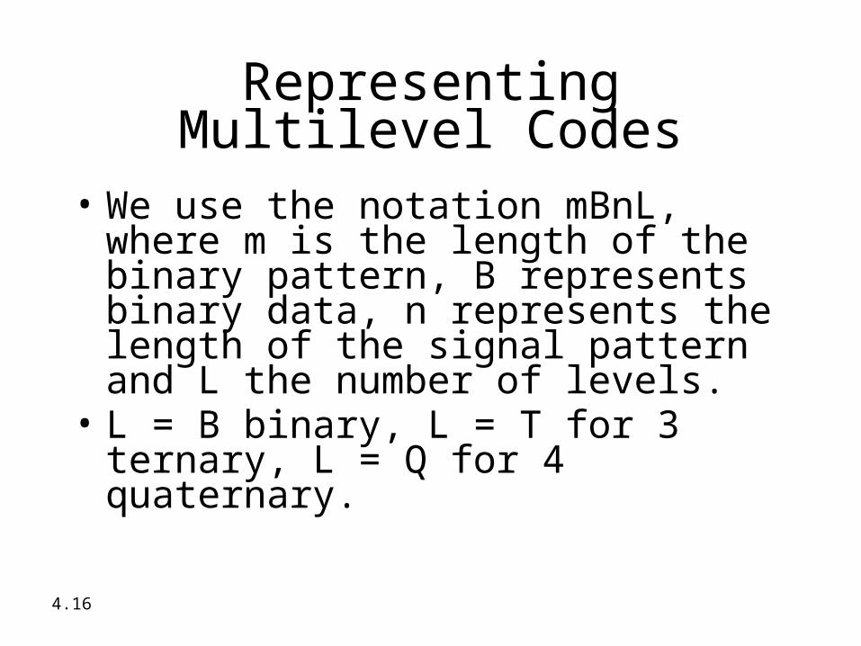
Representing Multilevel Codes
• We use the notation mBnL, where m is the length of the binary pattern, B represents binary data, n represents the length of the signal pattern and L the number of levels.
• L = B binary, L = T for 3 ternary, L = Q for 4 quaternary.

4.17
Figure 4.10 Multilevel: 2B1Q scheme

4.18
For example: B8ZS substitutes eight consecutive zeros with 000VB0VB.
The V stands for violation, it violates the line encoding rule
B stands for bipolar, it implements the bipolar line encoding rule

4.19
Figure 4.19 Two cases of B8ZS scrambling technique
4.20
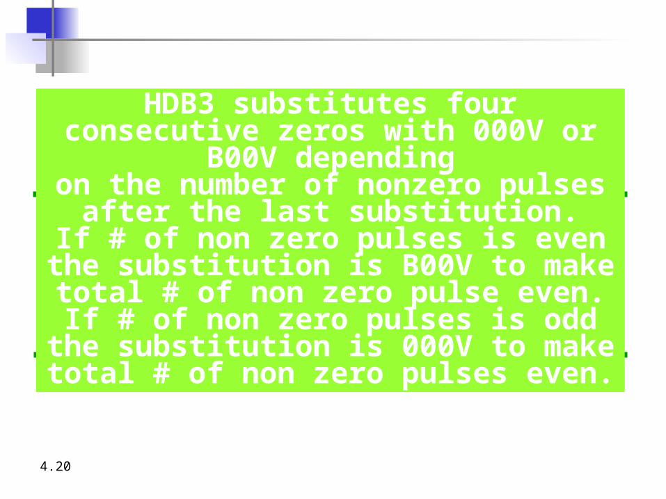
HDB3 substitutes four consecutive zeros with 000V or B00V depending
on the number of nonzero pulses after the last substitution.
If # of non zero pulses is even the substitution is B00V to make total # of
non zero pulse even.If # of non zero pulses is odd the
substitution is 000V to make total # of non zero pulses even.

4.21
Figure 4.20 Different situations in HDB3 scrambling technique

Line coding Scheme
Representation of 0
Representation of 1
Unipolar NRZ
Polar NRZ
Polar RZ
The signal level to the left of the bit is high Assumption:
•Include Slides 13 and 14 in the theory part

Line coding Scheme
Representation of 0
Representation of 1
NRZI
Manchester
Differential Manchester

Introduction
Credits
24
Definitions Test your understanding (questionnaire) Lets Sum up (summary) Want to know more…
(Further Reading)
Try it yourself
Interactivity:
Analogy
Slide 1
Slide 3
Slide 14,15
Slide 17
Slide 16
Electrical Engineering
Input Data
Digital Signal
Select the coding scheme
• Uni polar NRZ• Polar NRZ• Polar RZ• NRZI• Manchester• Differential Manchester
Enter 11 bit input data
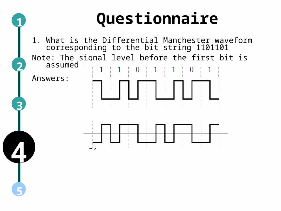
Questionnaire1. What is the Differential Manchester waveform corresponding to
the bit string 1101101Note: The signal level before the first bit is assumed to be high
Answers:
a)
b)
1
5
2
4
3
1
5
2
4
3
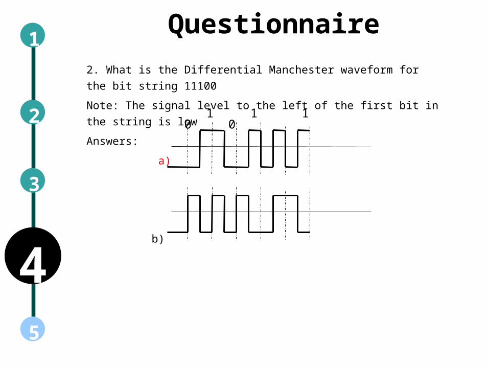
2. What is the Differential Manchester waveform for the bit string 11100
Note: The signal level to the left of the first bit in the string is low
Answers:
a)
b)
1 1 1 0 0
Questionnaire

Links for further reading
Reference websites:
Books: “Communication Systems” by Simon Haykin, fourth Edition
“Data and Computer Communications” by William Stallings, eighth Edition
Research papers:

Summary• Binary data can be transmitted using a number of different types of pulses.
The choice of a particular pair of pulses to represent the symbols 1 and 0 is called Line Coding.
• Line coding is the process of converting binary data, a sequence of bits to a digital signal.