Embed Size (px)
Citation preview
|||||||||||||||||||||||||||||||||||||||||||||||||||||||||||||||||||||||||||||||||||||||||||||||||||||||||||||||||||||||||||||||||
BRITISH STANDARD BS EN736-2 : 1997
The European Standard EN 736-2 : 1997 has the status of aBritish Standard
ICS 01.040.23; 23.060.01
NO COPYING WITHOUT BSI PERMISSION EXCEPT AS PERMITTED BY COPYRIGHT LAW
Valves Ð
Terminology
Part 2. Definition of components ofvalves
BS EN 736-2 : 1997
This British Standard, havingbeen prepared under thedirection of the Sector Board forEngineering, was published underthe authority of the StandardsBoard and comes into effect on15 December 1997
BSI 1997
ISBN 050 28905 2
Amendments issued since publication
Amd. No. Date Text affected
National foreword
This British Standard is the English language version of EN 736-2 : 1997.
The UK participation in its preparation was entrusted to Technical CommitteePSE/7/1. Valves Ð Basic standards. which has the responsibility to:
± aid enquirers to understand the text;
± present to the responsible European committee any enquiries on theinterpretation, or proposals for change, and keep the UK interests informed;
± monitor related international and European developments and promulgatethem in the UK.
A list of organizations represented on this committee can be obtained on request toits secretary.
Cross-references
The British Standards which implement international or European publicationsreferred to in this document may be found in the BSI Standards Catalogue under thesection entitled `International Standards Correspondence Index', or by using the`Find' facility of the BSI Standards Electronic Catalogue.
Compliance with a British Standard does not of itself confer immunityfrom legal obligations.
Summary of pages
This document comprises a front cover, an inside front cover, the EN title page,pages 2 to 10, an inside back cover and a back cover.
CENEuropean Committee for Standardization
Comite EuropeÂen de Normalisation
EuropaÈisches Komitee fuÈ r Normung
Central Secretariat: rue de Stassart 36, B-1050 Brussels
1997 CEN All rights of exploitation in any form and by any means reserved worldwide for CEN nationalMembers
Ref. No. EN 736-2 : 1997 E
EUROPEAN STANDARD EN 736-2
NORME EUROPEÂ ENNE
EUROPAÈ ISCHE NORM August 1997
ICS 01.040.23; 23.060.01
Descriptors: Valves and fittings, components, vocabulary, multilingual nomenclature
English version
Valves Ð Terminology Ð Part 2: Definition ofcomponents of valves
Appareils de robinetterie Ð Terminologie ÐPartie 2: DeÂfinition des composants desappareils de robinetterie
Armaturen Ð Terminologie ÐTeil 2: Definition der Armaturenteile
This European Standard was approved by CEN on 1997-07-24. CEN members arebound to comply with the CEN/CENELEC Internal Regulations which stipulate theconditions for giving this European Standard the status of a national standardwithout any alteration.
Up-to-date lists and bibliographical references concerning such national standardsmay be obtained on application to the Central Secretariat or to any CEN member.
This European Standard exists in three official versions (English, French, German).A version in any other language made by translation under the responsibility of aCEN member into its own language and notified to the Central Secretariat has thesame status as the official versions.
CEN members are the national standards bodies of Austria, Belgium, CzechRepublic, Denmark, Finland, France, Germany, Greece, Iceland, Ireland, Italy,Luxembourg, Netherlands, Norway, Portugal, Spain, Sweden, Switzerland andUnited Kingdom.
Page 2EN 736-2 : 1997
BSI 1997
Foreword
This European Standard has been prepared byTechnical Committee CEN/TC 69, Industrial valves, ofthe Secretariat which is held by AFNOR.
This European Standard shall be given the status of anational standard, either by publication of an identicaltext or by endorsement, at the latest by February 1998,and conflicting national standards shall be withdrawnat the latest by February 1998.
EN 736 comprises three parts:
Part 1: Definition of types of valves
Part 2: Definition of components of valves
Part 3: Definition of terms
According to the CEN/CENELEC Internal Regulations,the national standards organizations of the followingcountries are bound to implement this EuropeanStandard: Austria, Belgium, Czech Republic, Denmark,Finland, France, Germany, Greece, Iceland, Ireland,Italy, Luxembourg, Netherlands, Norway, Portugal,Spain, Sweden, Switzerland and the United Kingdom.
Contents
Page
Foreword 2
Introduction 3
1 Scope 3
2 Normative references 3
3 Definitions 3
Annex
A (informative) Glossary 7

Page 3EN 736-2 : 1997
BSI 1997
IntroductionThis is the first step in harmonizing the valveterminology in Europe. It is possible that other namesof components or other definitions will be found inother European Standards.
Experts establishing European Standards are asked touse the name of components and the definitions givenin this standard. If other names of components ordefinitions are needed or already published inEuropean Standards please contact the CEN/TC 69Secretariat for adding or harmonizing the names ofcomponents and their definitions in these EuropeanStandards.
1 ScopeThis standard specifies the names of components ofvalves and their definitions. It has the purpose toprovide a uniform terminology for all components ofvalves.
This standard covers components common to morethan one type of valve. Names of components anddefinitions specific to one type of valve will be foundin the relevant product or performance standard.
2 Normative referencesThis European Standard incorporates by dated orundated reference, provisions from other publications.These normative references are cited at theappropriate places in the text and the publications arelisted hereafter. For dated references, subsequentamendments to or revisions of any of thesepublications apply to this European Standard, onlywhen incorporated in it by amendment or revision. Forundated references the latest edition of the publicationreferred to applies.
EN 736-1 Valves Ð Terminology ÐPart 1: Definition of types of valves
prEN 736-3 Valves Ð Terminology ÐPart 3: Definition of terms
3 DefinitionsFor the purposes of this standard the followingdefinitions apply.
3.1 shell
Pressure containing envelope of the valve.
NOTE. It normally comprises the body and when included in thedesign a bonnet or cover and the body bonnet or body cover joint.
3.1.1 body
Main component of the valve which provides the fluidflow passageways and the body ends.
3.1.1.1 straight pattern body
Body having two body end ports and where the axis ofthe bonnet or cover is parallel to the faces of the bodyend ports.
3.1.1.2 angle pattern body
Body having two body end ports and where the facesare at right angles.
3.1.1.3 oblique pattern body
Body having two body end ports and where the axis ofthe bonnet or cover is not parallel to the faces of thebody end ports.
3.1.1.4 double flanged body
Body having two flanged body ends for connecting tocorresponding flanges.
3.1.1.5 single flanged body
A body with a single flange not being a body endflange, designed to be installed by bolting to adjacentpipe flange(s).
NOTE. It can be suitable to close the end of the pipe line allowingdismantling of the downstream pipe line.
3.1.1.6 lug type body
Body designed with threaded or unthreaded holes forbolting to the adjacent flange(s) of the pipeline.
3.1.1.7 wafer type body
Body designed to be installed by clamping betweenflanges.
3.1.1.8 multi end body
Body with more than two body end ports.
3.1.1.9 body end
Part of the body provided with the means ofconnection to the piping component (excluding by-passif fitted).
3.1.1.10 flanged end
Body end provided with a flange for mating with acorresponding flange.
3.1.1.11 welding end
Body end prepared for welding to a corresponding endof a component. Such body end can be of the buttwelding or socket welding type.
3.1.1.12 butt welding end
Body end prepared for welding to a component byabutting the ends and welding within the grooveformed between the prepared ends.
3.1.1.13 socket welding end
Body end prepared for insertion of a component endinto the socket and joining and sealing by filletwelding.
3.1.1.14 threaded end
Body end provided with internal or external thread formating with a corresponding threaded component.
3.1.1.15 socket end
Body end prepared for connection to a spigot end.
3.1.1.16 spigot end
Body end prepared for insertion in a socket.
Page 4EN 736-2 : 1997
BSI 1997
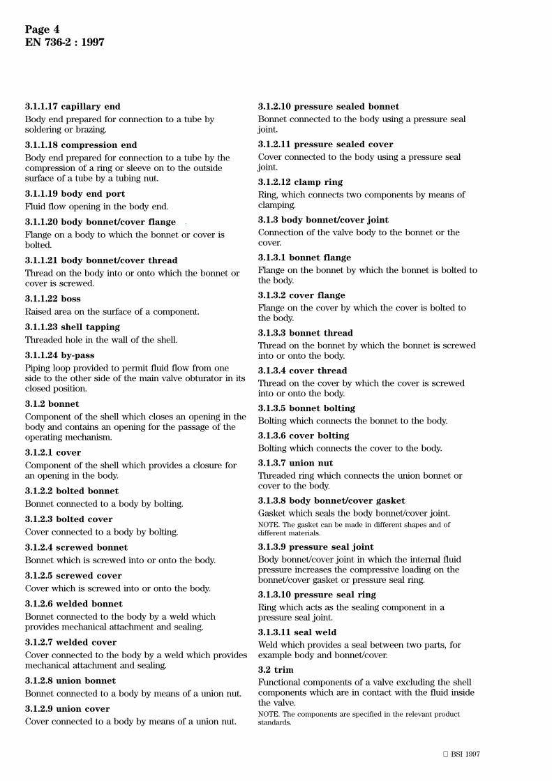
3.1.1.17 capillary end
Body end prepared for connection to a tube bysoldering or brazing.
3.1.1.18 compression end
Body end prepared for connection to a tube by thecompression of a ring or sleeve on to the outsidesurface of a tube by a tubing nut.
3.1.1.19 body end port
Fluid flow opening in the body end.
3.1.1.20 body bonnet/cover flange
Flange on a body to which the bonnet or cover isbolted.
3.1.1.21 body bonnet/cover thread
Thread on the body into or onto which the bonnet orcover is screwed.
3.1.1.22 boss
Raised area on the surface of a component.
3.1.1.23 shell tapping
Threaded hole in the wall of the shell.
3.1.1.24 by-pass
Piping loop provided to permit fluid flow from oneside to the other side of the main valve obturator in itsclosed position.
3.1.2 bonnet
Component of the shell which closes an opening in thebody and contains an opening for the passage of theoperating mechanism.
3.1.2.1 cover
Component of the shell which provides a closure foran opening in the body.
3.1.2.2 bolted bonnet
Bonnet connected to a body by bolting.
3.1.2.3 bolted cover
Cover connected to a body by bolting.
3.1.2.4 screwed bonnet
Bonnet which is screwed into or onto the body.
3.1.2.5 screwed cover
Cover which is screwed into or onto the body.
3.1.2.6 welded bonnet
Bonnet connected to the body by a weld whichprovides mechanical attachment and sealing.
3.1.2.7 welded cover
Cover connected to the body by a weld which providesmechanical attachment and sealing.
3.1.2.8 union bonnet
Bonnet connected to a body by means of a union nut.
3.1.2.9 union cover
Cover connected to a body by means of a union nut.
3.1.2.10 pressure sealed bonnet
Bonnet connected to the body using a pressure sealjoint.
3.1.2.11 pressure sealed cover
Cover connected to the body using a pressure sealjoint.
3.1.2.12 clamp ring
Ring, which connects two components by means ofclamping.
3.1.3 body bonnet/cover joint
Connection of the valve body to the bonnet or thecover.
3.1.3.1 bonnet flange
Flange on the bonnet by which the bonnet is bolted tothe body.
3.1.3.2 cover flange
Flange on the cover by which the cover is bolted tothe body.
3.1.3.3 bonnet thread
Thread on the bonnet by which the bonnet is screwedinto or onto the body.
3.1.3.4 cover thread
Thread on the cover by which the cover is screwedinto or onto the body.
3.1.3.5 bonnet bolting
Bolting which connects the bonnet to the body.
3.1.3.6 cover bolting
Bolting which connects the cover to the body.
3.1.3.7 union nut
Threaded ring which connects the union bonnet orcover to the body.
3.1.3.8 body bonnet/cover gasket
Gasket which seals the body bonnet/cover joint.NOTE. The gasket can be made in different shapes and ofdifferent materials.
3.1.3.9 pressure seal joint
Body bonnet/cover joint in which the internal fluidpressure increases the compressive loading on thebonnet/cover gasket or pressure seal ring.
3.1.3.10 pressure seal ring
Ring which acts as the sealing component in apressure seal joint.
3.1.3.11 seal weld
Weld which provides a seal between two parts, forexample body and bonnet/cover.
3.2 trim
Functional components of a valve excluding the shellcomponents which are in contact with the fluid insidethe valve.NOTE. The components are specified in the relevant productstandards.
Page 5EN 736-2 : 1997
BSI 1997
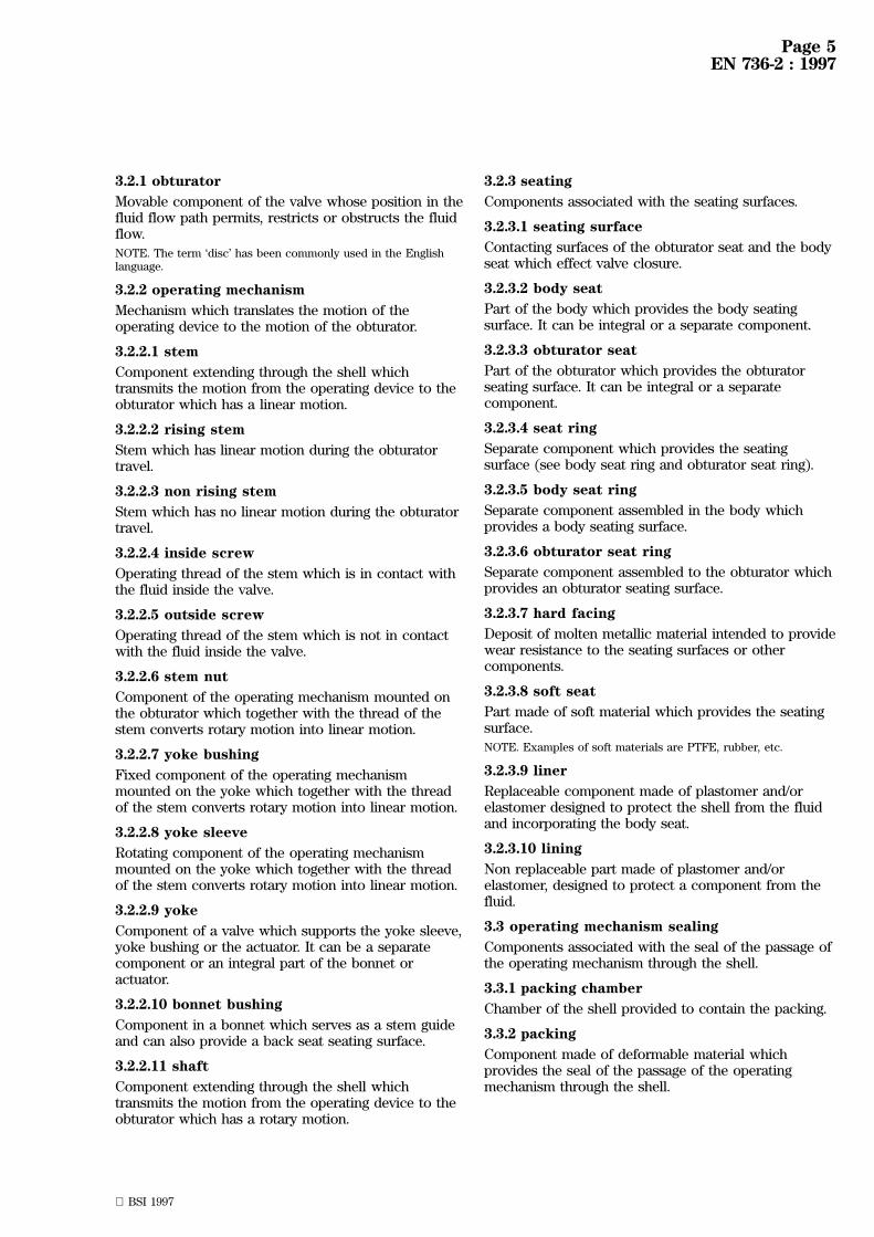
3.2.1 obturator
Movable component of the valve whose position in thefluid flow path permits, restricts or obstructs the fluidflow.
NOTE. The term `disc' has been commonly used in the Englishlanguage.
3.2.2 operating mechanism
Mechanism which translates the motion of theoperating device to the motion of the obturator.
3.2.2.1 stem
Component extending through the shell whichtransmits the motion from the operating device to theobturator which has a linear motion.
3.2.2.2 rising stem
Stem which has linear motion during the obturatortravel.
3.2.2.3 non rising stem
Stem which has no linear motion during the obturatortravel.
3.2.2.4 inside screw
Operating thread of the stem which is in contact withthe fluid inside the valve.
3.2.2.5 outside screw
Operating thread of the stem which is not in contactwith the fluid inside the valve.
3.2.2.6 stem nut
Component of the operating mechanism mounted onthe obturator which together with the thread of thestem converts rotary motion into linear motion.
3.2.2.7 yoke bushing
Fixed component of the operating mechanismmounted on the yoke which together with the threadof the stem converts rotary motion into linear motion.
3.2.2.8 yoke sleeve
Rotating component of the operating mechanismmounted on the yoke which together with the threadof the stem converts rotary motion into linear motion.
3.2.2.9 yoke
Component of a valve which supports the yoke sleeve,yoke bushing or the actuator. It can be a separatecomponent or an integral part of the bonnet oractuator.
3.2.2.10 bonnet bushing
Component in a bonnet which serves as a stem guideand can also provide a back seat seating surface.
3.2.2.11 shaft
Component extending through the shell whichtransmits the motion from the operating device to theobturator which has a rotary motion.
3.2.3 seating
Components associated with the seating surfaces.
3.2.3.1 seating surface
Contacting surfaces of the obturator seat and the bodyseat which effect valve closure.
3.2.3.2 body seat
Part of the body which provides the body seatingsurface. It can be integral or a separate component.
3.2.3.3 obturator seat
Part of the obturator which provides the obturatorseating surface. It can be integral or a separatecomponent.
3.2.3.4 seat ring
Separate component which provides the seatingsurface (see body seat ring and obturator seat ring).
3.2.3.5 body seat ring
Separate component assembled in the body whichprovides a body seating surface.
3.2.3.6 obturator seat ring
Separate component assembled to the obturator whichprovides an obturator seating surface.
3.2.3.7 hard facing
Deposit of molten metallic material intended to providewear resistance to the seating surfaces or othercomponents.
3.2.3.8 soft seat
Part made of soft material which provides the seatingsurface.
NOTE. Examples of soft materials are PTFE, rubber, etc.
3.2.3.9 liner
Replaceable component made of plastomer and/orelastomer designed to protect the shell from the fluidand incorporating the body seat.
3.2.3.10 lining
Non replaceable part made of plastomer and/orelastomer, designed to protect a component from thefluid.
3.3 operating mechanism sealing
Components associated with the seal of the passage ofthe operating mechanism through the shell.
3.3.1 packing chamber
Chamber of the shell provided to contain the packing.
3.3.2 packing
Component made of deformable material whichprovides the seal of the passage of the operatingmechanism through the shell.

Page 6EN 736-2 : 1997
BSI 1997
3.3.3 packing gland
Component used to compress the packing.
3.3.4 gland flange
Flange bearing against a packing gland used tocompress the packing.
3.3.5 gland nut
Nut bearing against the packing gland used tocompress the packing.
3.3.6 lantern ring
Rigid spacer used in the packing chamber to separatetwo packing sets.
3.3.7 bellows seal
Component utilizing a bellows which provides the sealof the passage of the operating mechanism through theshell.
3.3.8 soft seal
Component utilizing a resilient seal ring whichprovides the seal of the passage of the operatingmechanism through the shell.
3.3.9 seal ring bushing
Bushing designed to accept the seal ring(s) of a softsealed operating mechanism sealing.
3.3.10 diaphragm seal
Component utilizing a diaphragm which provides theseal of the passage of the operating mechanismthrough the shell.
3.3.11 back seat
Contacting seating surfaces on the bonnet or bonnetbushing and the stem or corresponding componentwhen the stem is fully retracted.
3.4 operating device
Manual or power operated device used to operate thebare valve.
3.4.1 operating element
Component of the operating device by which themechanical power is introduced.
NOTE. It can be mounted directly on the bare valve.
3.4.1.1 handwheel
Wheel designed to operate a valve by hand.
3.4.1.2 lever
Pivoting arm designed to operate a valve by hand.
3.4.1.3 chainwheel
Wheel designed to be operated by a chain.
3.4.1.4 actuator
Operating element which uses electrical, hydraulic orpneumatic power.
3.4.2 extension device
Component of the operating device which transmitsmechanically the motion of the operating element tothe operating mechanism of a bare valve when situatedapart from the operating element.
3.5 bare valve
Valve comprising shell, trim and operating mechanismsealing prepared for the attachment of the operatingdevice.
NOTE. The boundary between the bare valve and the operatingdevice is specified in the relevant product standard.
Page 7EN 736-2 : 1997
BSI 1997
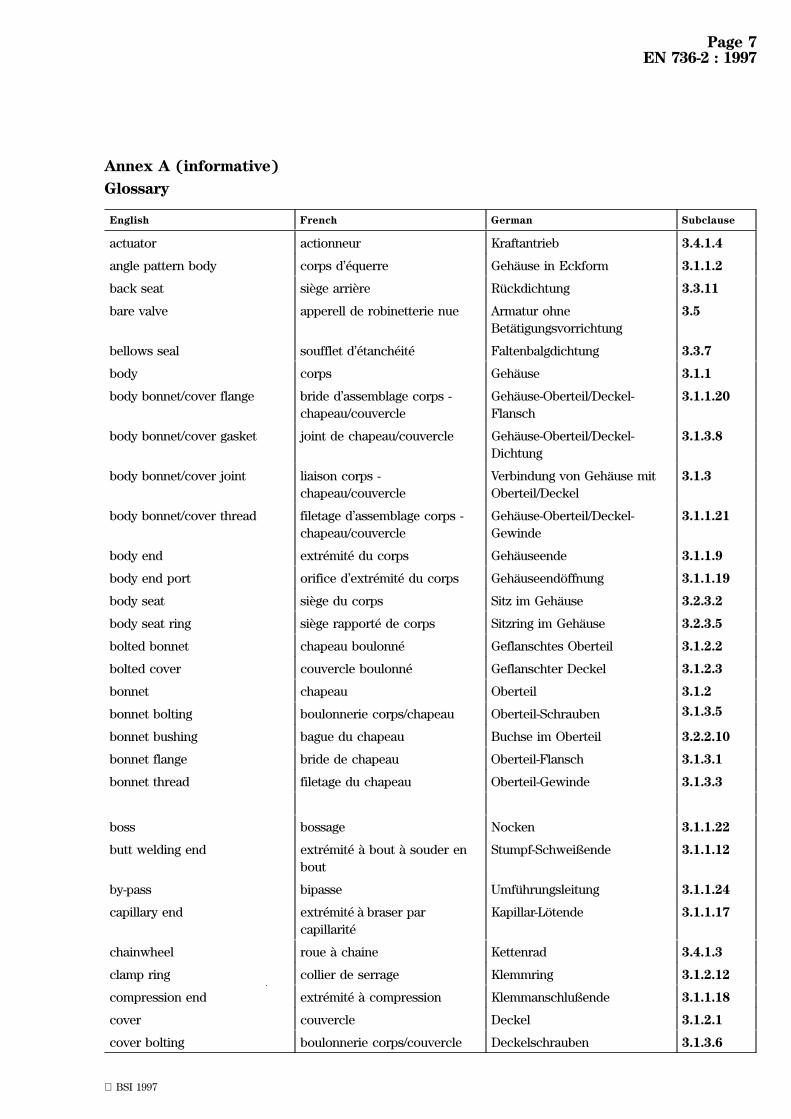
Annex A (informative)
Glossary
English French German Subclause
actuator actionneur Kraftantrieb 3.4.1.4
angle pattern body corps d'eÂquerre GehaÈuse in Eckform 3.1.1.2
back seat sieÁge arrieÁre RuÈckdichtung 3.3.11
bare valve apperell de robinetterie nue Armatur ohne
BetaÈtigungsvorrichtung
3.5
bellows seal soufflet d'eÂtancheÂite Faltenbalgdichtung 3.3.7
body corps GehaÈuse 3.1.1
body bonnet/cover flange bride d'assemblage corps -
chapeau/couvercle
GehaÈuse-Oberteil/Deckel-
Flansch
3.1.1.20
body bonnet/cover gasket joint de chapeau/couvercle GehaÈuse-Oberteil/Deckel-
Dichtung
3.1.3.8
body bonnet/cover joint liaison corps -
chapeau/couvercle
Verbindung von GehaÈuse mit
Oberteil/Deckel
3.1.3
body bonnet/cover thread filetage d'assemblage corps -
chapeau/couvercle
GehaÈuse-Oberteil/Deckel-
Gewinde
3.1.1.21
body end extreÂmite du corps GehaÈuseende 3.1.1.9
body end port orifice d'extreÂmite du corps GehaÈuseendoÈ ffnung 3.1.1.19
body seat sieÁge du corps Sitz im GehaÈuse 3.2.3.2
body seat ring sieÁge rapporte de corps Sitzring im GehaÈuse 3.2.3.5
bolted bonnet chapeau boulonne Geflanschtes Oberteil 3.1.2.2
bolted cover couvercle boulonne Geflanschter Deckel 3.1.2.3
bonnet chapeau Oberteil 3.1.2
bonnet bolting boulonnerie corps/chapeau Oberteil-Schrauben 3.1.3.5
bonnet bushing bague du chapeau Buchse im Oberteil 3.2.2.10
bonnet flange bride de chapeau Oberteil-Flansch 3.1.3.1
bonnet thread filetage du chapeau Oberteil-Gewinde 3.1.3.3
boss bossage Nocken 3.1.1.22
butt welding end extreÂmite aÁ bout aÁ souder en
bout
Stumpf-Schweiûende 3.1.1.12
by-pass bipasse UmfuÈhrungsleitung 3.1.1.24
capillary end extreÂmite aÁ braser par
capillariteÂ
Kapillar-LoÈ tende 3.1.1.17
chainwheel roue aÁ chaine Kettenrad 3.4.1.3
clamp ring collier de serrage Klemmring 3.1.2.12
compression end extreÂmite aÁ compression Klemmanschluûende 3.1.1.18
cover couvercle Deckel 3.1.2.1
cover bolting boulonnerie corps/couvercle Deckelschrauben 3.1.3.6

Page 8EN 736-2 : 1997
BSI 1997
English French German Subclause
cover flange bride de couvercle Deckelflansch 3.1.3.2
cover thread filetage du couvercle Deckelgewinde 3.1.3.4
diaphragm seal membrane d'etancheÂite Membrandichtung 3.3.10
double flanged body corps aÁ brides GehaÈuse mit zwei Flanschen 3.1.1.4
extension device dispositif intermediaire VerlaÈngerungsvorrichtung 3.4.2
flanged end extreÂmite aÁ bride Flanschanschluû 3.1.1.10
gland flange bride de fouloir Stopfbuchsflansch 3.3.4
gland nut eÂcrou de fouloir Stopfbuchsmutter 3.3.5
handwheel volant de manoeuvre Handrad 3.4.1.1
hard facing reveÃtement dur Panzerung 3.2.3.7
inside screw filetage inteÂrieur Innenliegendes Spindelgewinde 3.2.2.4
lantern ring lanterne Sperrkammerring 3.3.6
lever levier de manoeuvre Handhebel 3.4.1.2
liner manchette Manschette 3.2.3.9
lining reveÃtement Interne Auskleidung 3.2.3.10
lug type body corps aÁ oreilles Lug-Type-GehaÈuse 3.1.1.6
multi-end body corps multi-voies Mehrwege-GehaÈuse 3.1.1.8
non rising stem tige non-montante Nichtsteigende Spindel 3.2.2.3
oblique pattern body corps aÁ teÃte inclineÂe GehaÈuse mit schrûaÈgem
Oberteil
3.1.1.3
obturator obturateur AbschluûkoÈrper 3.2.1
obturator seat sieÁge d'obturateur Sitz am AbschlubûkoÈrper 3.2.3.3
obturator seat ring sieÁge rapporte d'obturateur Sitzring am AbschluûkoÈrper 3.2.3.6
operating device dispositif de manoeuvre BetaÈtigungsvorrichtung 3.4
operating element organe de manoeuvre BetaÈtigungselement 3.4.1
operating mechanism meÂcanisme de manoeuvre BetaÈtigungsorgan 3.2.2
operating mechanism sealing dispositif d'eÂtancheÂite du
meÂcanisme de manoeuvre
Abdichtung des
BetaÈtigungsorgans
3.3
outside screw filetage exteÂrieur Auûenliegendes
Spindelgewinde
3.2.2.5
packing garniture d'eÂtancheÂite Packung 3.3.2
packing chamber logement de la garniture Packungsraum 3.3.1
packing gland fouloir StopfbuchsbuÈchse 3.3.3
pressure seal joint liaison autoclave Druckdichtende Verbindung 3.1.3.9
pressure seal ring joint autoclave Druckdichtender Ring 3.1.3.10
pressure sealed bonnet bague d'eÂtancheÂite autoclave Druckdichtendes Oberteil 3.1.2.10
pressure sealed cover couvercle aÁ liaison autoclave Druckdichtender Deckel 3.1.2.11
rising stem tige montante Steigende Spindel 3.2.2.2
screwed bonnet chapeau visse Verschraubtes Oberteil 3.1.2.4

Page 9EN 736-2 : 1997
BSI 1997
English French German Subclause
screwed cover couvercle visse Verschraubter Deckel 3.1.2.5
seal ring bushing bague porte-joints Dichtringbuchse 3.3.9
seal weld soudure d'eÂtancheÂite Dichtschweiûung 3.1.3.11
seat ring sieÁge rapporte Sitzring 3.2.3.4
seating sieÁge Sitz 3.2.3
seating surface porteÂe d'etancheite SitzoberflaÈche 3.2.3.1
shaft arbre Welle 3.2.2.11
shell enveloppe Drucktragendes GehaÈuse 3.1
shell tapping raccordement auxiliaire Anbohrung im drucktragenden
GehaÈuse
3.1.1.23
single flanged body corps monobride MonoflanschgehaÈuse 3.1.1.5
socket end extreÂmite aÁ emboõÃter femelle Muffenende 3.1.1.15
socket welding end extreÂmite aÁ emboõÃter et aÁ
souder
Schweiûmuffenende 3.1.1.13
soft seal eÂtancheÂite souple Weichdictung 3.3.8
soft seat sieÁge souple Weichdichtender Sitz 3.2.3.8
spigot end extreÂmite aÁ emboõÃter maÃle Spitzende 3.1.1.16
stem tige Spindel 3.2.2.1
stem nut eÂcrou de tige Spindelmutter 3.2.2.6
straight pattern body corps aÁ teÃte droite GehaÈuse in Durchgangsform 3.1.1.1
threaded end extreÂmite fileteÂe Gewindeende 3.1.1.14
trim eÂquipement interne AusruÈstung 3.2
union bonnet chapeau union Oberteil mitUÈ berwurfmutter 3.1.2.8
union cover couvercle union Deckel mit UÈ berwurfmutter 3.1.2.9
union nut eÂcrou de raccord union UÈ berwurfmutter 3.1.3.7
wafer type body corps aÁ inseÂrer EinklemmgehaÈuse 3.1.1.7
welded bonnet chapeau soude Verschweiûtes Oberteil 3.1.2.6
welded cover couvercle soude Verschweiûter Deckel 3.1.2.7
welding end extreÂmite souder Schweiûende 3.1.1.11
yoke arcade BuÈgelaufsatz 3.2.2.9
yoke bushing eÂcrou de tige (fixe) Buchse im BuÈgelaufsatz 3.2.2.7
yoke sleeve eÂcrou de tige (tournant) Gewindebuchse im
BuÈgelaufsatz
3.2.2.8
BSI389 Chiswick High RoadLondonW4 4AL
|||||||||||||||||||||||||||||||||||||||||||||||||||||||||||||||||||||||||||||||||||||||||||||||||||||||||||||||||||||||||||||||
BSI Ð British Standards Institution
BSI is the independent national body responsible for preparing British Standards. Itpresents the UK view on standards in Europe and at the international level. It isincorporated by Royal Charter.
Revisions
British Standards are updated by amendment or revision. Users of British Standardsshould make sure that they possess the latest amendments or editions.
It is the constant aim of BSI to improve the quality of our products and services. Wewould be grateful if anyone finding an inaccuracy or ambiguity while using thisBritish Standard would inform the Secretary of the technical committee responsible,the identity of which can be found on the inside front cover. Tel: 020 8996 9000.Fax: 020 8996 7400.
BSI offers members an individual updating service called PLUS which ensures thatsubscribers automatically receive the latest editions of standards.
Buying standards
Orders for all BSI, international and foreign standards publications should beaddressed to Customer Services. Tel: 020 8996 9001. Fax: 020 8996 7001.
In response to orders for international standards, it is BSI policy to supply the BSIimplementation of those that have been published as British Standards, unlessotherwise requested.
Information on standards
BSI provides a wide range of information on national, European and internationalstandards through its Library and its Technical Help to Exporters Service. VariousBSI electronic information services are also available which give details on all itsproducts and services. Contact the Information Centre. Tel: 020 8996 7111.Fax: 020 8996 7048.
Subscribing members of BSI are kept up to date with standards developments andreceive substantial discounts on the purchase price of standards. For details ofthese and other benefits contact Membership Administration. Tel: 020 8996 7002.Fax: 020 8996 7001.
Copyright
Copyright subsists in all BSI publications. BSI also holds the copyright, in the UK, ofthe publications of the international standardization bodies. Except as permittedunder the Copyright, Designs and Patents Act 1988 no extract may be reproduced,stored in a retrieval system or transmitted in any form or by any means ± electronic,photocopying, recording or otherwise ± without prior written permission from BSI.
This does not preclude the free use, in the course of implementing the standard, ofnecessary details such as symbols, and size, type or grade designations. If thesedetails are to be used for any other purpose than implementation then the priorwritten permission of BSI must be obtained.
If permission is granted, the terms may include royalty payments or a licensingagreement. Details and advice can be obtained from the Copyright Manager.Tel: 020 8996 7070.