Embed Size (px)
Citation preview
00012916:99900131:
Model 12916 Crane
Section 1 SPECIFICATIONSSection 2 CRANE REFERENCESection 3 REPLACEMENT PARTSSection 4 GENERAL REFERENCE
IOWA MOLD TOOLING CO., INC.BOX 189, GARNER, IA 50438-0189
TEL: 641-923-3711
MANUAL PART NUMBER 99900131
Volume 2 - PARTS AND SPECIFICATIONS
20120322
Iowa Mold Tooling Co., Inc. is an Oshkosh Corporation company.
00012916:99900131:REVISIONS LIST
DATE LOCATION DESCRIPTION OF CHANGE- - -20011127 3-22 - 24 ECN 8794 - NEW HYD OVERLOAD VALVE BLOCK
4-1, 14 ECN 8780 - WARRANTY3-26 CORRECTED INCORRECT PART NUMBER FOR DUMP VALVE. WAS 73054979, SHOULD BE
73055278.20011210 3-25 ECN 8834 - NEW FLOOD LIGHT KIT20020128 3-22,23 ITEM #11 WAS 72532679, NOW 7253214120020318 3-5 MOBILTAC 375NC NOTE
3-24 ADDED 31717514 CAP ALERT KIT20020801 3-24 ECN 8958 - UPDATED 31717169, 31717514 CAP ALERT/SHUTDOWN KITS
3-25 ECN 8972 - ADDED GROMMET & CLAMP TO FLOOD LIGHT KIT20021022 3-26 ECN 9009 - NEW HYD SHUTDOWN VALVE20021202 3-25 ECN 9064 - ADDED 51717977 LIGHT KIT20030325 3-12,13 ECN 9127 - REPLACED 3B116513 WITH NEW CYLINDER, 5171806520030520 3-16,17 ECN 9075 - CHANGED HOSE DIA. AND REDUCED FITTINGS ON VALVE BANK RETURN20050712 3-17 ECN 9782-1 - CHANGE TO CLAMP PLATE ON 9370887620060616 3-6,8,10,12 ECN 9832-2 - REVERSE CYLINDER CHANGE20060714 2-5 ECN 10169 - CHANGED HYD FILTER RETURN ELEMENT PART20061020 1-1,3-3 UPDATED OWNERSHIP STATEMENT, ADDED SERIAL TAG LOCATIONS20070705 3-13 ECN 10299 - UPDATE TO 5171806520071008 3-25 ECN 10425-ADD WASHERS TO 51717977
3-14 ECN 10429 - CORRECTIONS TO HYD SHUTDOWN KIT 917039463-17 ECN 10523 - HOSE CLAMP 72661642 WAS 72066516
20111221 THROUGHOUT ECN 11628 - UPDATED STABILIZER WORDING, ADDED STAB. DEPLOY DECALS, CRANE LEVEL3-14,22,23 ECN 11621 - HYDRAULIC OVERLOAD KIT
20120322 3-6,9,32 ECN 11615 - CYLINDER REVISIONS, ADDED TETH RMT POT ADJUSTMENT TO MANUAL
--------
00012916:99900131:
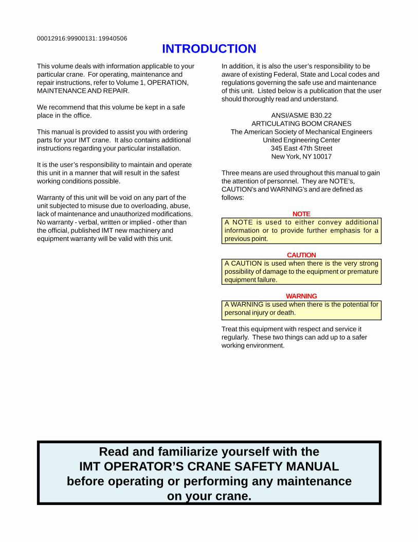
INTRODUCTION
Read and familiarize yourself with theIMT OPERATOR’S CRANE SAFETY MANUAL
before operating or performing any maintenanceon your crane.
19940506
This volume deals with information applicable to yourparticular crane. For operating, maintenance andrepair instructions, refer to Volume 1, OPERATION,MAINTENANCE AND REPAIR.
We recommend that this volume be kept in a safeplace in the office.
This manual is provided to assist you with orderingparts for your IMT crane. It also contains additionalinstructions regarding your particular installation.
It is the user’s responsibility to maintain and operatethis unit in a manner that will result in the safestworking conditions possible.
Warranty of this unit will be void on any part of theunit subjected to misuse due to overloading, abuse,lack of maintenance and unauthorized modifications.No warranty - verbal, written or implied - other thanthe official, published IMT new machinery andequipment warranty will be valid with this unit.
In addition, it is also the user’s responsibility to beaware of existing Federal, State and Local codes andregulations governing the safe use and maintenanceof this unit. Listed below is a publication that the usershould thoroughly read and understand.
ANSI/ASME B30.22ARTICULATING BOOM CRANES
The American Society of Mechanical EngineersUnited Engineering Center
345 East 47th StreetNew York, NY 10017
Three means are used throughout this manual to gainthe attention of personnel. They are NOTE’s,CAUTION’s and WARNING’s and are defined asfollows:
NOTEA NOTE is used to either convey additionalinformation or to provide further emphasis for aprevious point.
CAUTIONA CAUTION is used when there is the very strongpossibility of damage to the equipment or prematureequipment failure.
WARNINGA WARNING is used when there is the potential forpersonal injury or death.
Treat this equipment with respect and service itregularly. These two things can add up to a saferworking environment.

00012916:99900131: 20000728NOTES
00012916:99900131: 1-119940415
SECTION 1. 12916 CRANE SPECIFICATIONS
GENERAL SPECIFICATIONS ................................................................................... 3
PERFORMANCE CHARACTERISTICS .................................................................... 4
POWER SOURCE....................................................................................................... 4
CYLINDER HOLDING VALVES ................................................................................. 4
ROTATION SYSTEM .................................................................................................. 4
HYDRAULIC SYSTEM................................................................................................ 4
STABILIZER DIMENSIONS ........................................................................................ 4
GEOMETRIC CONFIGURATION................................................................................ 5
CAPACITY CHART .................................................................................................... 6
MINIMUM CHASSIS SPECIFICATIONS .................................................................... 7

00012916:99900131: 1-2NOTES
19940415
00012916:99900131: 1-3
IOWA MOLD TOOLING CO., INC.BOX 189, GARNER, IA 50438-0189
TEL: 641-923-3711 FAX: 641-923-2424
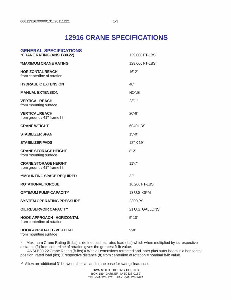
12916 CRANE SPECIFICATIONS
20111221
GENERAL SPECIFICATIONS*CRANE RATING (ANSI B30.22) 129,000 FT-LBS
*MAXIMUM CRANE RATING 129,000 FT-LBS
HORIZONTAL REACH 16'-2'’from centerline of rotation
HYDRAULIC EXTENSION 40'’
MANUAL EXTENSION NONE
VERTICAL REACH 23'-1'’from mounting surface
VERTICAL REACH 26'-6'’from ground / 41'’ frame ht.
CRANE WEIGHT 6040 LBS
STABILIZER SPAN 15'-0'’
STABILIZER PADS 12'’ X 19'’
CRANE STORAGE HEIGHT 8'-2'’from mounting surface
CRANE STORAGE HEIGHT 11'-7'’from ground / 41'’ frame ht.
**MOUNTING SPACE REQUIRED 32'’
ROTATIONAL TORQUE 16,200 FT-LBS
OPTIMUM PUMP CAPACITY 13 U.S. GPM
SYSTEM OPERATING PRESSURE 2300 PSI
OIL RESERVOIR CAPACITY 21 U.S. GALLONS
HOOK APPROACH - HORIZONTAL 5'-10'’from centerline of rotation
HOOK APPROACH - VERTICAL 9'-8'’from mounting surface
* Maximum Crane Rating (ft-lbs) is defined as that rated load (lbs) which when multiplied by its respectivedistance (ft) from centerline of rotation gives the greatest ft-lb value.
ANSI B30.22 Crane Rating (ft-lbs) = With all extensions retracted and inner plus outer boom in a horizontalposition, rated load (lbs) X respective distance (ft) from centerline of rotation = nominal ft-lb value.
** Allow an additional 3'’ between the cab and crane base for swing clearance.
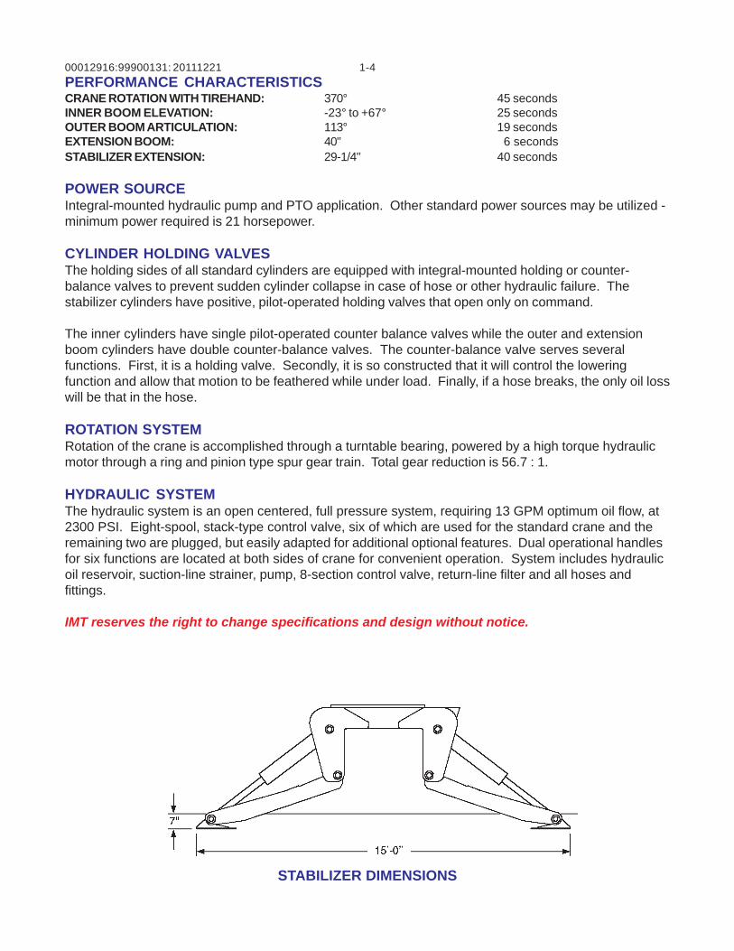
00012916:99900131: 1-420111221PERFORMANCE CHARACTERISTICSCRANE ROTATION WITH TIREHAND: 370° 45 secondsINNER BOOM ELEVATION: -23° to +67° 25 secondsOUTER BOOM ARTICULATION: 113° 19 secondsEXTENSION BOOM: 40'’ 6 secondsSTABILIZER EXTENSION: 29-1/4'’ 40 seconds
POWER SOURCEIntegral-mounted hydraulic pump and PTO application. Other standard power sources may be utilized -minimum power required is 21 horsepower.
CYLINDER HOLDING VALVESThe holding sides of all standard cylinders are equipped with integral-mounted holding or counter-balance valves to prevent sudden cylinder collapse in case of hose or other hydraulic failure. Thestabilizer cylinders have positive, pilot-operated holding valves that open only on command.
The inner cylinders have single pilot-operated counter balance valves while the outer and extensionboom cylinders have double counter-balance valves. The counter-balance valve serves severalfunctions. First, it is a holding valve. Secondly, it is so constructed that it will control the loweringfunction and allow that motion to be feathered while under load. Finally, if a hose breaks, the only oil losswill be that in the hose.
ROTATION SYSTEMRotation of the crane is accomplished through a turntable bearing, powered by a high torque hydraulicmotor through a ring and pinion type spur gear train. Total gear reduction is 56.7 : 1.
HYDRAULIC SYSTEMThe hydraulic system is an open centered, full pressure system, requiring 13 GPM optimum oil flow, at2300 PSI. Eight-spool, stack-type control valve, six of which are used for the standard crane and theremaining two are plugged, but easily adapted for additional optional features. Dual operational handlesfor six functions are located at both sides of crane for convenient operation. System includes hydraulicoil reservoir, suction-line strainer, pump, 8-section control valve, return-line filter and all hoses andfittings.
IMT reserves the right to change specifications and design without notice.
STABILIZER DIMENSIONS
00012916:99900131: 1-519970702
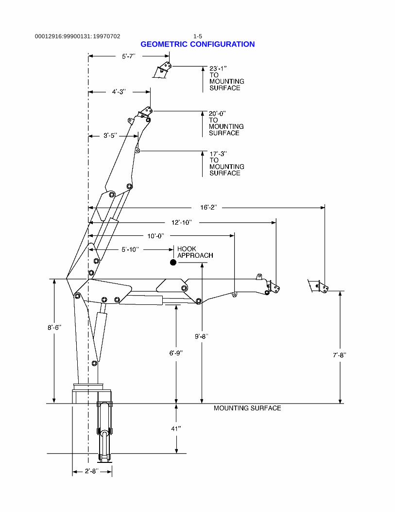
GEOMETRIC CONFIGURATION
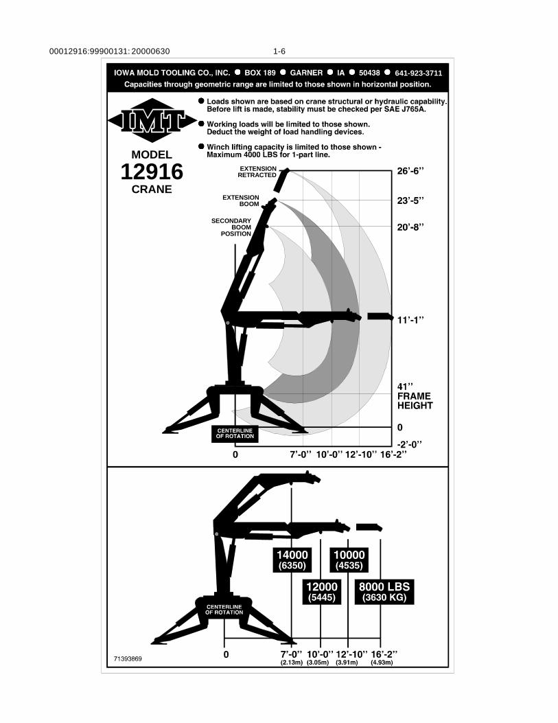
00012916:99900131: 1-620000630
MODEL
CRANE12916 EXTENSION
RETRACTED
SECONDARYBOOM
POSITION
EXTENSIONBOOM
641-923-3711
00012916:99900131: 1-720000905
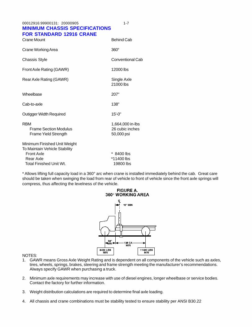
MINIMUM CHASSIS SPECIFICATIONSFOR STANDARD 12916 CRANECrane Mount Behind Cab
Crane Working Area 360°
Chassis Style Conventional Cab
Front Axle Rating (GAWR) 12000 lbs
Rear Axle Rating (GAWR) Single Axle21000 lbs
Wheelbase 207"
Cab-to-axle 138"
Outigger Width Required 15'-0"
RBM 1,664,000 in-lbsFrame Section Modulus 26 cubic inchesFrame Yield Strength 50,000 psi
Minimum Finished Unit WeightTo Maintain Vehicle Stability Front Axle * 8400 lbs Rear Axle *11400 lbs Total Finished Unit Wt. 19800 lbs
* Allows lifting full capacity load in a 360° arc when crane is installed immediately behind the cab. Great careshould be taken when swinging the load from rear of vehicle to front of vehicle since the front axle springs willcompress, thus affecting the levelness of the vehicle.
NOTES:1. GAWR means Gross Axle Weight Rating and is dependent on all components of the vehicle such as axles,
tires, wheels, springs, brakes, steering and frame strength meeting the manufacturer’s recommendations.Always specify GAWR when purchasing a truck.
2. Minimum axle requirements may increase with use of diesel engines, longer wheelbase or service bodies.Contact the factory for further information.
3. Weight distribution calculations are required to determine final axle loading.
4. All chassis and crane combinations must be stability tested to ensure stability per ANSI B30.22

00012916:99900131: 1-820000630
IOWA MOLD TOOLING CO., INC.BOX 189, GARNER, IA 50438-0189
TEL: 641-923-3711FAX: 641-923-2424
00012916:99900131: 2-119940506
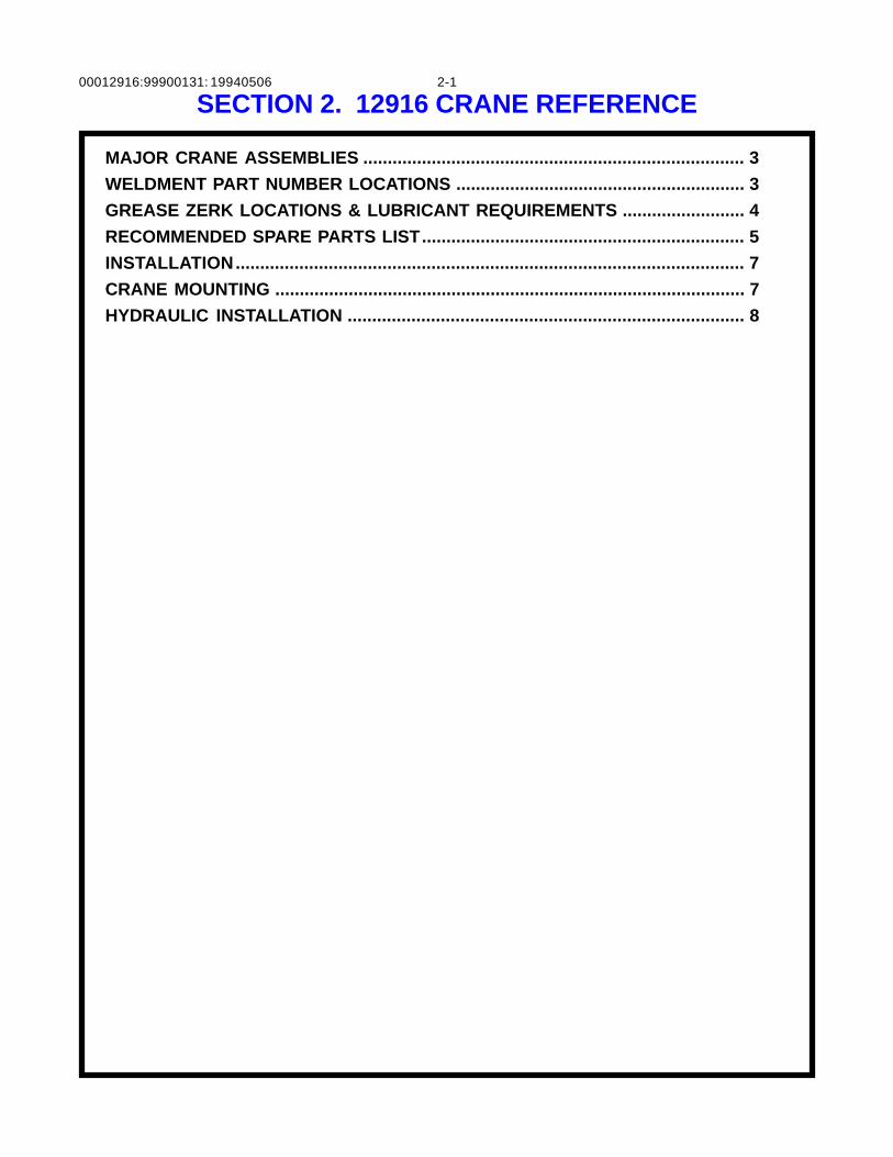
SECTION 2. 12916 CRANE REFERENCE
MAJOR CRANE ASSEMBLIES .............................................................................. 3
WELDMENT PART NUMBER LOCATIONS ........................................................... 3
GREASE ZERK LOCATIONS & LUBRICANT REQUIREMENTS ......................... 4
RECOMMENDED SPARE PARTS LIST.................................................................. 5
INSTALLATION........................................................................................................ 7
CRANE MOUNTING ................................................................................................ 7
HYDRAULIC INSTALLATION ................................................................................. 8

00012916:99900131: 2-2NOTES
19940506
00012916:99900131: 2-319940506
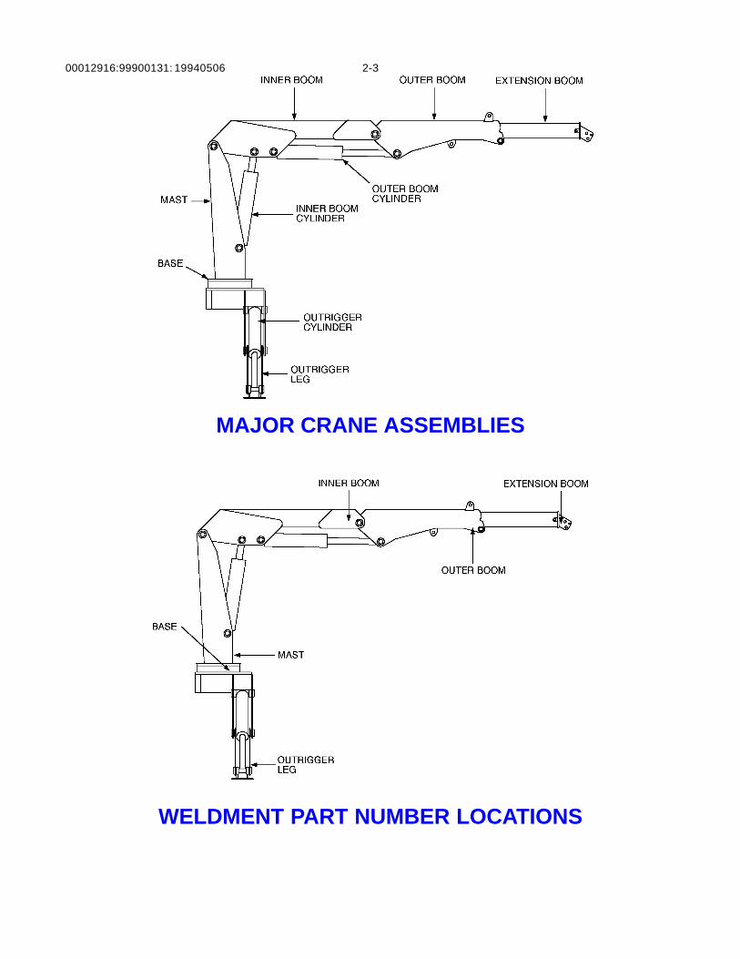
MAJOR CRANE ASSEMBLIES
WELDMENT PART NUMBER LOCATIONS
00012916:99900131: 2-4
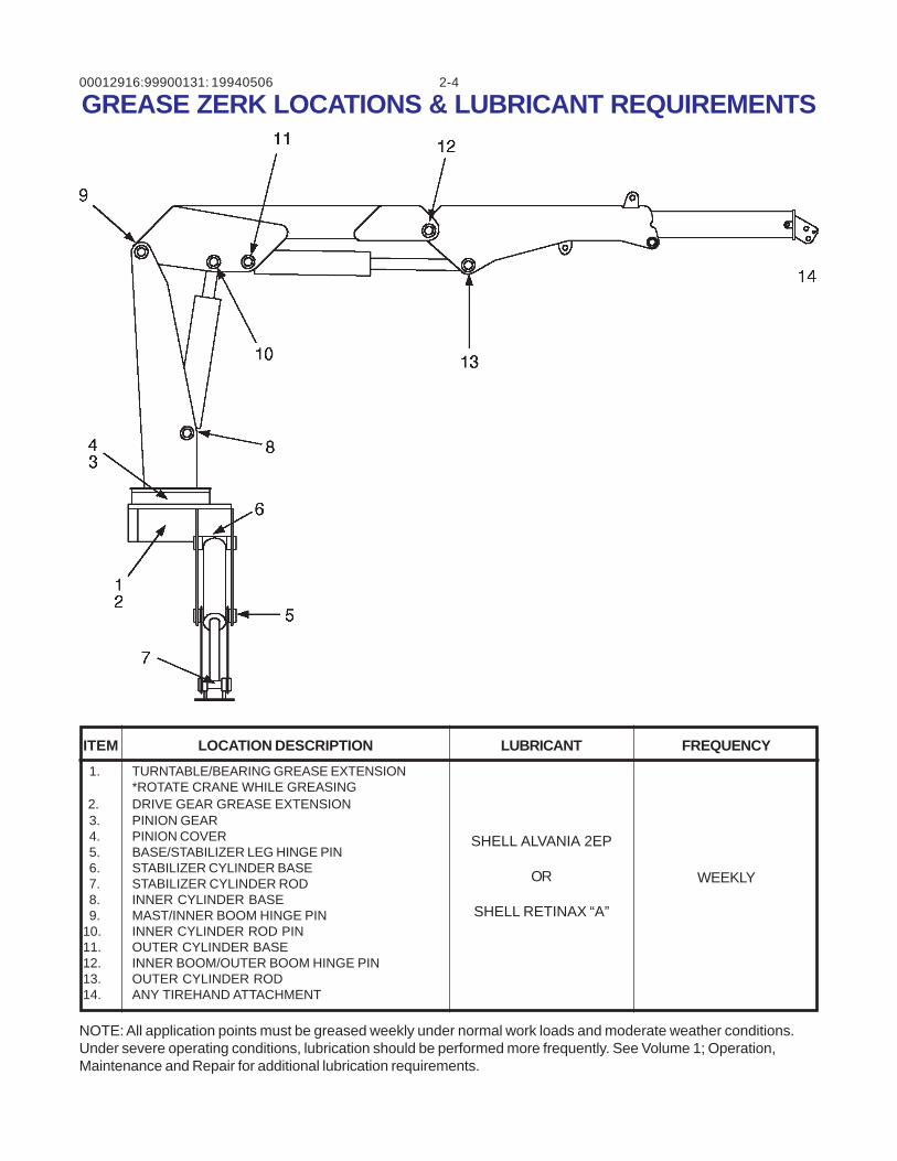
GREASE ZERK LOCATIONS & LUBRICANT REQUIREMENTS
NOTE: All application points must be greased weekly under normal work loads and moderate weather conditions.Under severe operating conditions, lubrication should be performed more frequently. See Volume 1; Operation,Maintenance and Repair for additional lubrication requirements.
ITEM LOCATION DESCRIPTION LUBRICANT FREQUENCY
1. TURNTABLE/BEARING GREASE EXTENSION*ROTATE CRANE WHILE GREASING
2. DRIVE GEAR GREASE EXTENSION 3. PINION GEAR 4. PINION COVER 5. BASE/STABILIZER LEG HINGE PIN 6. STABILIZER CYLINDER BASE 7. STABILIZER CYLINDER ROD 8. INNER CYLINDER BASE 9. MAST/INNER BOOM HINGE PIN 10. INNER CYLINDER ROD PIN 11. OUTER CYLINDER BASE 12. INNER BOOM/OUTER BOOM HINGE PIN 13. OUTER CYLINDER ROD 14. ANY TIREHAND ATTACHMENT
SHELL ALVANIA 2EP
OR
SHELL RETINAX “A”
WEEKLY
19940506
00012916:99900131: 2-520111221
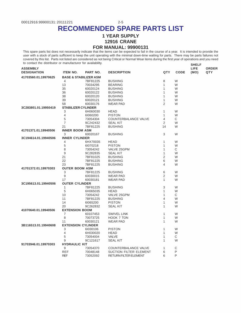
RECOMMENDED SPARE PARTS LIST1 YEAR SUPPLY12916 CRANE
FOR MANUAL: 99900131This spare parts list does not necessarily indicate that the items can be expected to fail in the course of a year. It is intended to provide theuser with a stock of parts sufficient to keep the unit operating with the minimal down-time waiting for parts. There may be parts failures notcovered by this list. Parts not listed are considered as not being Critical or Normal Wear items during the first year of operations and you needto contact the distributor or manufacturer for availability. SHELF
LIFE(MO)
ORDERQTYCODEQTYDESCRIPTIONPART NO.ITEM NO.
ASSEMBLYDESIGNATION
41703560.01.19970625 BASE & STABILIZER ASM 4 7BF81225 BUSHING 8 W13 70034295 BEARING 1 W35 60020124 BUSHING 1 W36 60020122 BUSHING 1 W38 60020120 BUSHING 1 W39 60020121 BUSHING 1 W58 60030176 WEAR PAD 2 W
3C283801.01.19950419 STABILIZER CYLINDER 3 6H060030 HEAD 1 W 4 6I060200 PISTON 1 W 5 73054304 COUNTERBALANCE VALVE 4 C 7 9C242432 SEAL KIT 2 W21 7BF81225 BUSHING 14 W
41701371.01.19940506 INNER BOOM ASM 3 60020167 BUSHING 3 W
3C194614.01.19940506 INNER CYLINDER 4 6HX70035 HEAD 1 W 5 6I070218 PISTON 1 W 8 73054242 VALVE 25GPM 1 C 9 9C282835 SEAL KIT 1 W21 7BF81025 BUSHING 2 W22 7BF81225 BUSHING 6 W23 7BF81225 BUSHING 4 W
41701372.01.19970303 OUTER BOOM ASM 3 7BF81225 BUSHING 6 W 9 60030015 WEAR PAD 2 W17 60030181 WEAR PAD 1 W
3C195613.01.19940506 OUTER CYLINDER 1 7BF81225 BUSHING 3 W 5 6H065035 HEAD 1 W10 73054242 VALVE 25GPM 1 C11 7BF81225 BUSHING 4 W14 6I065200 PISTON 1 W20 9C262832 SEAL KIT 1 W
41070640.01.19940506 EXTENSION BOOM 7 60107453 SWIVEL LINK 1 W 8 70073725 HOOK 7 TON 1 W11 60030121 WEAR PAD 1 W
3B116513.01.19940608 EXTENSION CYLINDER 3 6I030106 PISTON 1 W 4 6H030020 HEAD 1 W 5 73054004 VALVE 1 C 9 9C121617 SEAL KIT 1 W
91703946.01.19970303 HYDRAULIC KIT 9 73054370 COUNTERBALANCE VALVE 1 CREF 70048148 SUCTION FILTER ELEMENT 6 PREF 73052092 RETURN FILTER ELEMENT 6 P

00012916:99900131: 2-619980127NOTES
00012916:99900131: 2-719960102
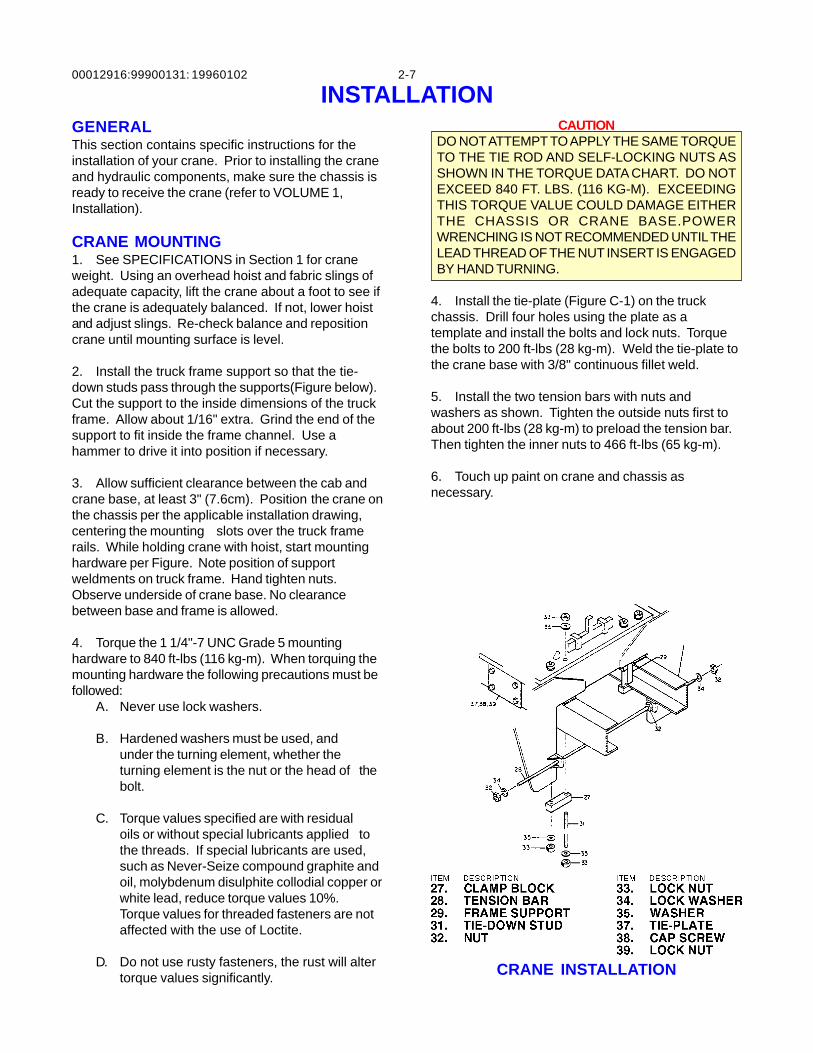
INSTALLATIONGENERALThis section contains specific instructions for theinstallation of your crane. Prior to installing the craneand hydraulic components, make sure the chassis isready to receive the crane (refer to VOLUME 1,Installation).
CRANE MOUNTING1. See SPECIFICATIONS in Section 1 for craneweight. Using an overhead hoist and fabric slings ofadequate capacity, lift the crane about a foot to see ifthe crane is adequately balanced. If not, lower hoistand adjust slings. Re-check balance and repositioncrane until mounting surface is level.
2. Install the truck frame support so that the tie-down studs pass through the supports(Figure below).Cut the support to the inside dimensions of the truckframe. Allow about 1/16" extra. Grind the end of thesupport to fit inside the frame channel. Use ahammer to drive it into position if necessary.
3. Allow sufficient clearance between the cab andcrane base, at least 3" (7.6cm). Position the crane onthe chassis per the applicable installation drawing,centering the mounting slots over the truck framerails. While holding crane with hoist, start mountinghardware per Figure. Note position of supportweldments on truck frame. Hand tighten nuts.Observe underside of crane base. No clearancebetween base and frame is allowed.
4. Torque the 1 1/4"-7 UNC Grade 5 mountinghardware to 840 ft-lbs (116 kg-m). When torquing themounting hardware the following precautions must befollowed:
A. Never use lock washers.
B. Hardened washers must be used, andunder the turning element, whether theturning element is the nut or the head of thebolt.
C. Torque values specified are with residualoils or without special lubricants applied tothe threads. If special lubricants are used,such as Never-Seize compound graphite andoil, molybdenum disulphite collodial copper orwhite lead, reduce torque values 10%.Torque values for threaded fasteners are notaffected with the use of Loctite.
D. Do not use rusty fasteners, the rust will altertorque values significantly.
CAUTIONDO NOT ATTEMPT TO APPLY THE SAME TORQUETO THE TIE ROD AND SELF-LOCKING NUTS ASSHOWN IN THE TORQUE DATA CHART. DO NOTEXCEED 840 FT. LBS. (116 KG-M). EXCEEDINGTHIS TORQUE VALUE COULD DAMAGE EITHERTHE CHASSIS OR CRANE BASE.POWERWRENCHING IS NOT RECOMMENDED UNTIL THELEAD THREAD OF THE NUT INSERT IS ENGAGEDBY HAND TURNING.
4. Install the tie-plate (Figure C-1) on the truckchassis. Drill four holes using the plate as atemplate and install the bolts and lock nuts. Torquethe bolts to 200 ft-lbs (28 kg-m). Weld the tie-plate tothe crane base with 3/8" continuous fillet weld.
5. Install the two tension bars with nuts andwashers as shown. Tighten the outside nuts first toabout 200 ft-lbs (28 kg-m) to preload the tension bar.Then tighten the inner nuts to 466 ft-lbs (65 kg-m).
6. Touch up paint on crane and chassis asnecessary.
CRANE INSTALLATION
00012916:99900131: 2-819960102
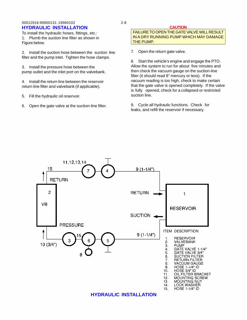
HYDRAULIC INSTALLATION
HYDRAULIC INSTALLATIONTo install the hydraulic hoses, fittings, etc.:1. Plumb the suction line filter as shown inFigure below.
2. Install the suction hose between the suction linefilter and the pump inlet. Tighten the hose clamps.
3. Install the pressure hose between thepump outlet and the inlet port on the valvebank.
4. Install the return line between the reservoirreturn line filter and valvebank (if applicable).
5. Fill the hydraulic oil reservoir.
6. Open the gate valve at the suction-line filter.
CAUTIONFAILURE TO OPEN THE GATE VALVE WILL RESULTIN A DRY RUNNING PUMP WHICH MAY DAMAGETHE PUMP.
7. Open the return gate valve.
8. Start the vehicle’s engine and engage the PTO.Allow the system to run for about five minutes andthen check the vacuum gauge on the suction-linefilter (it should read 8" mercury or less). If thevacuum reading is too high, check to make certainthat the gate valve is opened completely. If the valveis fully opened, check for a collapsed or restrictedsuction line.
9. Cycle all hydraulic functions. Check forleaks, and refill the reservoir if necessary.
00012916: 3-199900131:20021022
SECTION 3. REPLACEMENT PARTS 12916 CRANE
PARTS INFORMATION ................................................................................................. 3
BASE & STABILIZER ASM (41703560-1) .................................................................... 4
BASE & STABILIZER ASM (41703560-2) .................................................................... 5
STABILIZER CYLINDER (3C283801) .......................................................................... 6
MAST ASM (41701370) ................................................................................................. 7
INNER BOOM ASM (41701371) ................................................................................... 8
INNER CYLINDER (3C194614) .................................................................................... 9
OUTER BOOM ASM (41701372) ................................................................................ 10
OUTER CYLINDER (3C195613) ................................................................................ 11
EXTENSION BOOM (41070640) ................................................................................ 12
EXTENSION CYLINDER (51718065) ......................................................................... 13
HYD KIT-6 SECT (91703946) ..................................................................................... 14
CONTROL KIT-MNL 6F (90704441) ........................................................................... 15
VALVEBANK ASM-8 SECT MNL (51706642) ............................................................ 16
VALVEBANK-8 SECT MNL (51706643) .................................................................... 16
INSTALLATION KIT-MNL CTRLS (93708876) ........................................................... 17
DECAL KIT (95712299-1) ........................................................................................... 18
DECAL KIT (95712299-2) ........................................................................................... 19
CONVERSION KIT-STABILIZER CYLINDER LOCK (95711163) .............................. 21
HYD OVERLOAD KIT-3F (51717130)......................................................................... 22
HYD OVERLOAD KIT-4F (51717128)......................................................................... 23
CAPACITY ALERT KIT - 2800 PSI (31717169) .......................................................... 24
LIGHT KIT-CRANE MAST MOUNTED (51717977) (EFF. 11/15/02) ........................... 25
OPTION - LIGHT KIT (31717218) (thru 11/15/02) ....................................................... 26
OPTION-HYD SHUTDOWN KIT (31713788) (EFF 9-4-02) ........................................ 27
OPTION-HYD SHUTDOWN KIT (31713788) (THRU 9-3-02) ..................................... 28
REMOTE CONTROL KIT-V20R 6R/2M (90713581) ................................................... 29
PROP’L RMT CTRL KIT-6F (90713576) .................................................................... 30
RMT HANDLE ASM-6F (51713430) ........................................................................... 31
CABLE ASM-JIC BOX 50" (51713570) ...................................................................... 32
TETHERED PROPORTIONAL REMOTE POTENTIOMETER ADJUSTMENT ......... 32
HYDRAULIC SHUT-DOWN KIT (31713788) .............................................................. 33

00012916: 3-299900131:19980826
00012916: 3-3
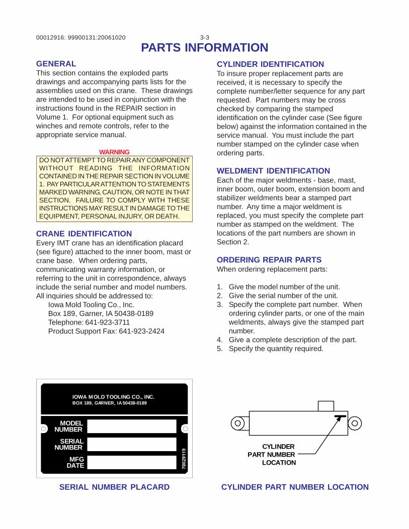
GENERALThis section contains the exploded partsdrawings and accompanying parts lists for theassemblies used on this crane. These drawingsare intended to be used in conjunction with theinstructions found in the REPAIR section inVolume 1. For optional equipment such aswinches and remote controls, refer to theappropriate service manual.
WARNINGDO NOT ATTEMPT TO REPAIR ANY COMPONENTWITHOUT READING THE INFORMATIONCONTAINED IN THE REPAIR SECTION IN VOLUME1. PAY PARTICULAR ATTENTION TO STATEMENTSMARKED WARNING, CAUTION, OR NOTE IN THATSECTION. FAILURE TO COMPLY WITH THESEINSTRUCTIONS MAY RESULT IN DAMAGE TO THEEQUIPMENT, PERSONAL INJURY, OR DEATH.
CRANE IDENTIFICATIONEvery IMT crane has an identification placard(see figure) attached to the inner boom, mast orcrane base. When ordering parts,communicating warranty information, orreferring to the unit in correspondence, alwaysinclude the serial number and model numbers.All inquiries should be addressed to:
Iowa Mold Tooling Co., Inc.Box 189, Garner, IA 50438-0189Telephone: 641-923-3711Product Support Fax: 641-923-2424
PARTS INFORMATIONCYLINDER IDENTIFICATIONTo insure proper replacement parts arereceived, it is necessary to specify thecomplete number/letter sequence for any partrequested. Part numbers may be crosschecked by comparing the stampedidentification on the cylinder case (See figurebelow) against the information contained in theservice manual. You must include the partnumber stamped on the cylinder case whenordering parts.
WELDMENT IDENTIFICATIONEach of the major weldments - base, mast,inner boom, outer boom, extension boom andstabilizer weldments bear a stamped partnumber. Any time a major weldment isreplaced, you must specify the complete partnumber as stamped on the weldment. Thelocations of the part numbers are shown inSection 2.
ORDERING REPAIR PARTSWhen ordering replacement parts:
1. Give the model number of the unit.2. Give the serial number of the unit.3. Specify the complete part number. When
ordering cylinder parts, or one of the mainweldments, always give the stamped partnumber.
4. Give a complete description of the part.5. Specify the quantity required.
SERIAL NUMBER PLACARD CYLINDER PART NUMBER LOCATION
99900131:20061020
MODELNUMBER
SERIALNUMBER
MFGDATE
IOWA MOLD TOOLING CO., INC.BOX 189, GARNER, IA 50438-0189
CYLINDERPART NUMBER
LOCATION
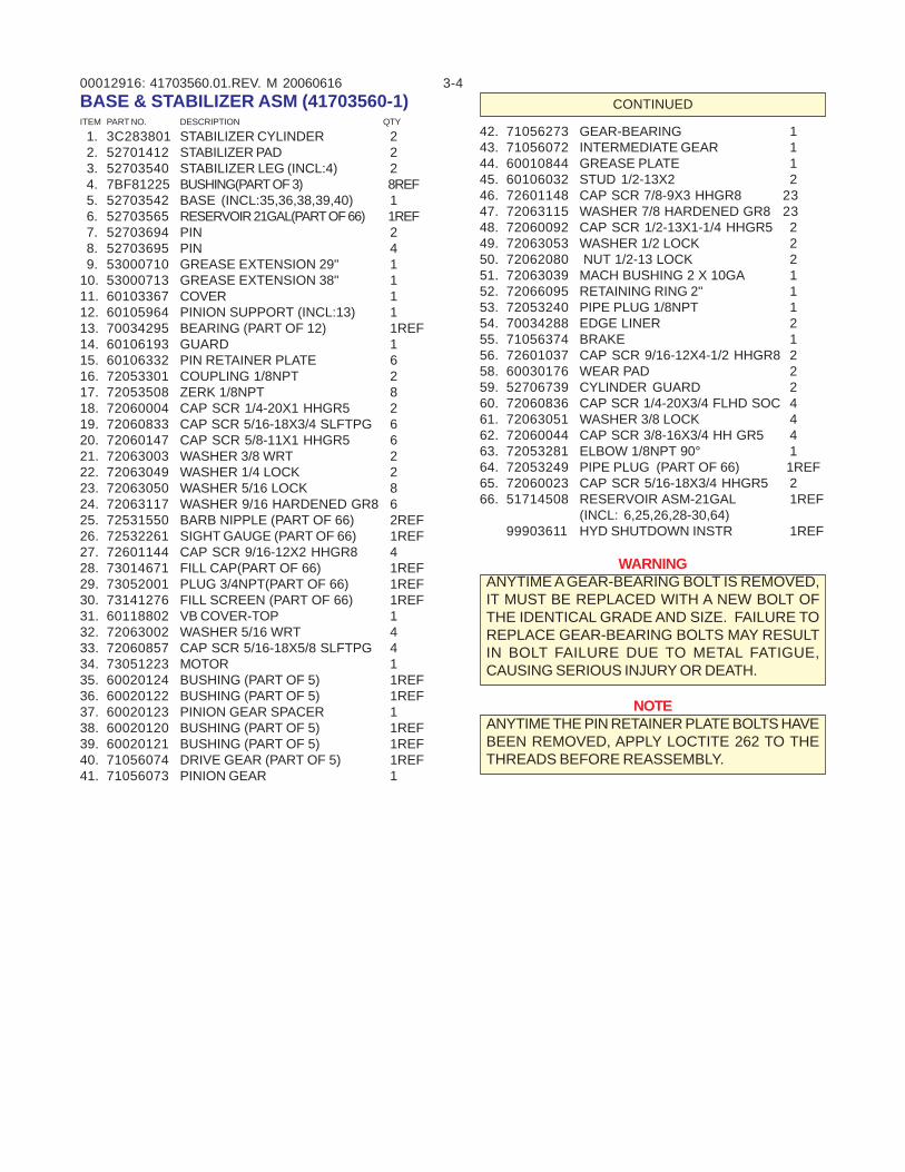
00012916: 3-441703560.01.REV. M 20060616BASE & STABILIZER ASM (41703560-1)ITEM PART NO. DESCRIPTION QTY
1. 3C283801 STABILIZER CYLINDER 2 2. 52701412 STABILIZER PAD 2 3. 52703540 STABILIZER LEG (INCL:4) 2 4. 7BF81225 BUSHING(PART OF 3) 8REF 5. 52703542 BASE (INCL:35,36,38,39,40) 1 6. 52703565 RESERVOIR 21GAL(PART OF 66) 1REF 7. 52703694 PIN 2 8. 52703695 PIN 4 9. 53000710 GREASE EXTENSION 29" 110. 53000713 GREASE EXTENSION 38" 111. 60103367 COVER 112. 60105964 PINION SUPPORT (INCL:13) 113. 70034295 BEARING (PART OF 12) 1REF14. 60106193 GUARD 115. 60106332 PIN RETAINER PLATE 616. 72053301 COUPLING 1/8NPT 217. 72053508 ZERK 1/8NPT 818. 72060004 CAP SCR 1/4-20X1 HHGR5 219. 72060833 CAP SCR 5/16-18X3/4 SLFTPG 620. 72060147 CAP SCR 5/8-11X1 HHGR5 621. 72063003 WASHER 3/8 WRT 222. 72063049 WASHER 1/4 LOCK 223. 72063050 WASHER 5/16 LOCK 824. 72063117 WASHER 9/16 HARDENED GR8 625. 72531550 BARB NIPPLE (PART OF 66) 2REF26. 72532261 SIGHT GAUGE (PART OF 66) 1REF27. 72601144 CAP SCR 9/16-12X2 HHGR8 428. 73014671 FILL CAP(PART OF 66) 1REF29. 73052001 PLUG 3/4NPT(PART OF 66) 1REF30. 73141276 FILL SCREEN (PART OF 66) 1REF31. 60118802 VB COVER-TOP 132. 72063002 WASHER 5/16 WRT 433. 72060857 CAP SCR 5/16-18X5/8 SLFTPG 434. 73051223 MOTOR 135. 60020124 BUSHING (PART OF 5) 1REF36. 60020122 BUSHING (PART OF 5) 1REF37. 60020123 PINION GEAR SPACER 138. 60020120 BUSHING (PART OF 5) 1REF39. 60020121 BUSHING (PART OF 5) 1REF40. 71056074 DRIVE GEAR (PART OF 5) 1REF41. 71056073 PINION GEAR 1
42. 71056273 GEAR-BEARING 143. 71056072 INTERMEDIATE GEAR 144. 60010844 GREASE PLATE 145. 60106032 STUD 1/2-13X2 246. 72601148 CAP SCR 7/8-9X3 HHGR8 2347. 72063115 WASHER 7/8 HARDENED GR8 2348. 72060092 CAP SCR 1/2-13X1-1/4 HHGR5 249. 72063053 WASHER 1/2 LOCK 250. 72062080 NUT 1/2-13 LOCK 251. 72063039 MACH BUSHING 2 X 10GA 152. 72066095 RETAINING RING 2" 153. 72053240 PIPE PLUG 1/8NPT 154. 70034288 EDGE LINER 255. 71056374 BRAKE 156. 72601037 CAP SCR 9/16-12X4-1/2 HHGR8 258. 60030176 WEAR PAD 259. 52706739 CYLINDER GUARD 260. 72060836 CAP SCR 1/4-20X3/4 FLHD SOC 461. 72063051 WASHER 3/8 LOCK 462. 72060044 CAP SCR 3/8-16X3/4 HH GR5 463. 72053281 ELBOW 1/8NPT 90° 164. 72053249 PIPE PLUG (PART OF 66) 1REF65. 72060023 CAP SCR 5/16-18X3/4 HHGR5 266. 51714508 RESERVOIR ASM-21GAL 1REF
(INCL: 6,25,26,28-30,64)99903611 HYD SHUTDOWN INSTR 1REF
WARNINGANYTIME A GEAR-BEARING BOLT IS REMOVED,IT MUST BE REPLACED WITH A NEW BOLT OFTHE IDENTICAL GRADE AND SIZE. FAILURE TOREPLACE GEAR-BEARING BOLTS MAY RESULTIN BOLT FAILURE DUE TO METAL FATIGUE,CAUSING SERIOUS INJURY OR DEATH.
NOTEANYTIME THE PIN RETAINER PLATE BOLTS HAVEBEEN REMOVED, APPLY LOCTITE 262 TO THETHREADS BEFORE REASSEMBLY.
CONTINUED
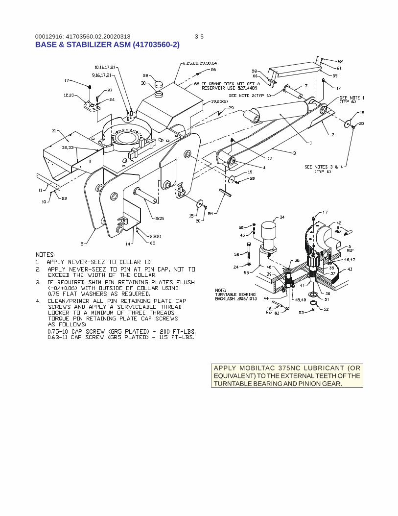
00012916: 3-541703560.02.20020318BASE & STABILIZER ASM (41703560-2)
APPLY MOBILTAC 375NC LUBRICANT (OREQUIVALENT) TO THE EXTERNAL TEETH OF THETURNTABLE BEARING AND PINION GEAR.
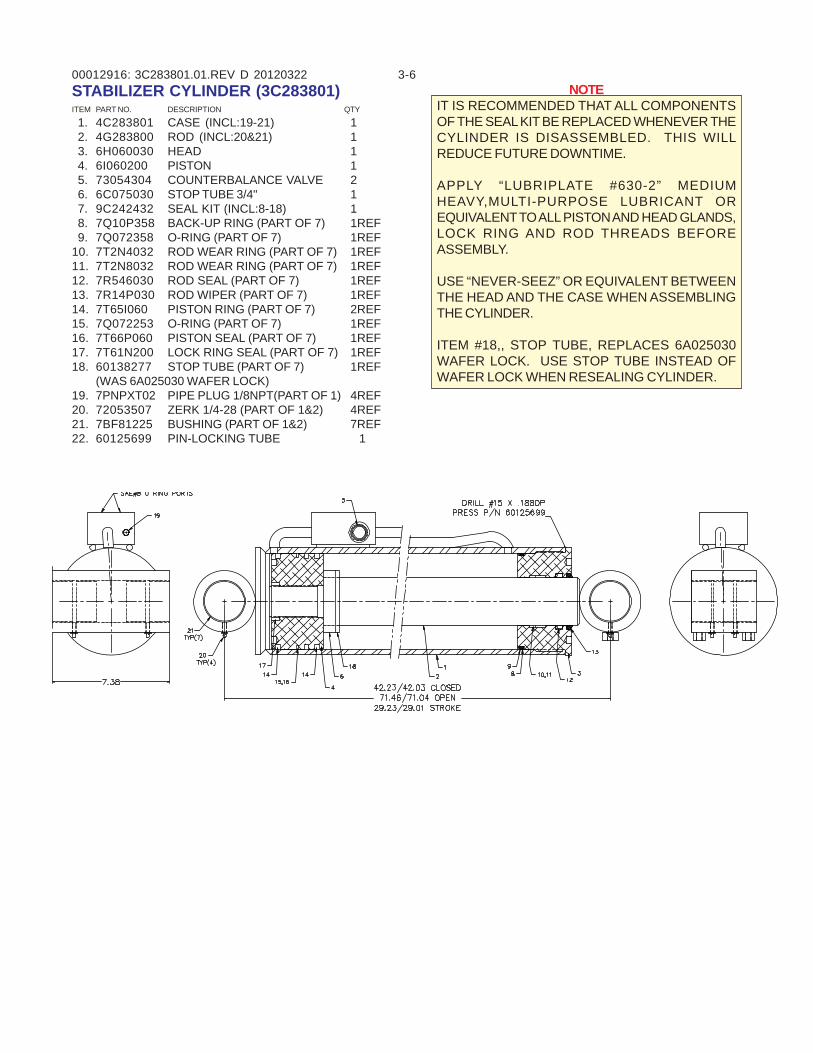
00012916: 3-63C283801.01.REV D 20120322STABILIZER CYLINDER (3C283801)ITEM PART NO. DESCRIPTION QTY
1. 4C283801 CASE (INCL:19-21) 1 2. 4G283800 ROD (INCL:20&21) 1 3. 6H060030 HEAD 1 4. 6I060200 PISTON 1 5. 73054304 COUNTERBALANCE VALVE 2 6. 6C075030 STOP TUBE 3/4" 1 7. 9C242432 SEAL KIT (INCL:8-18) 1 8. 7Q10P358 BACK-UP RING (PART OF 7) 1REF 9. 7Q072358 O-RING (PART OF 7) 1REF10. 7T2N4032 ROD WEAR RING (PART OF 7) 1REF11. 7T2N8032 ROD WEAR RING (PART OF 7) 1REF12. 7R546030 ROD SEAL (PART OF 7) 1REF13. 7R14P030 ROD WIPER (PART OF 7) 1REF14. 7T65I060 PISTON RING (PART OF 7) 2REF15. 7Q072253 O-RING (PART OF 7) 1REF16. 7T66P060 PISTON SEAL (PART OF 7) 1REF17. 7T61N200 LOCK RING SEAL (PART OF 7) 1REF18. 60138277 STOP TUBE (PART OF 7) 1REF
(WAS 6A025030 WAFER LOCK)19. 7PNPXT02 PIPE PLUG 1/8NPT(PART OF 1) 4REF20. 72053507 ZERK 1/4-28 (PART OF 1&2) 4REF21. 7BF81225 BUSHING (PART OF 1&2) 7REF22. 60125699 PIN-LOCKING TUBE 1
NOTEIT IS RECOMMENDED THAT ALL COMPONENTSOF THE SEAL KIT BE REPLACED WHENEVER THECYLINDER IS DISASSEMBLED. THIS WILLREDUCE FUTURE DOWNTIME.
APPLY “LUBRIPLATE #630-2” MEDIUMHEAVY,MULTI-PURPOSE LUBRICANT OREQUIVALENT TO ALL PISTON AND HEAD GLANDS,LOCK RING AND ROD THREADS BEFOREASSEMBLY.
USE “NEVER-SEEZ” OR EQUIVALENT BETWEENTHE HEAD AND THE CASE WHEN ASSEMBLINGTHE CYLINDER.
ITEM #18,, STOP TUBE, REPLACES 6A025030WAFER LOCK. USE STOP TUBE INSTEAD OFWAFER LOCK WHEN RESEALING CYLINDER.
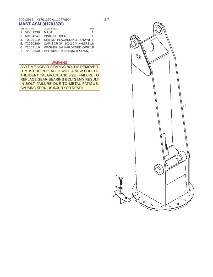
00012916: 3-741701370.01.19970904MAST ASM (41701370)ITEM PART NO. DESCRIPTION QTY
1. 52701338 MAST 1 2. 60104247 PINION COVER 1 3. 70029119 SER NO. PLACARD(NOT SHWN) 1 5. 72060209 CAP SCR 3/4-10X2-3/4 HHGR8 18 6. 72063116 WASHER 3/4 HARDENED GR8 18 7. 72066340 POP RIVET 1/8X3/8 (NOT SHWN) 2
WARNINGANYTIME A GEAR-BEARING BOLT IS REMOVED,IT MUST BE REPLACED WITH A NEW BOLT OFTHE IDENTICAL GRADE AND SIZE. FAILURE TOREPLACE GEAR-BEARING BOLTS MAY RESULTIN BOLT FAILURE DUE TO METAL FATIGUE,CAUSING SERIOUS INJURY OR DEATH.
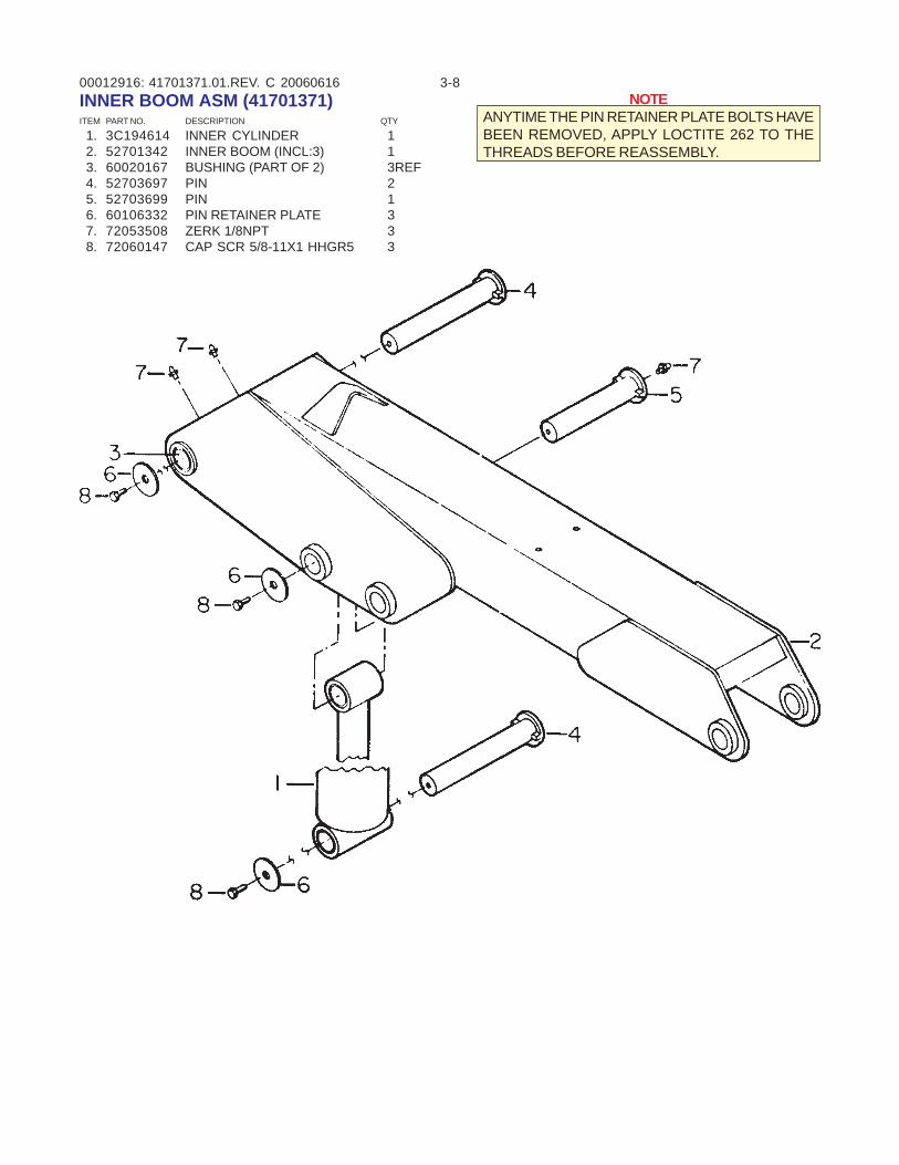
00012916: 3-841701371.01.REV. C 20060616INNER BOOM ASM (41701371)ITEM PART NO. DESCRIPTION QTY
1. 3C194614 INNER CYLINDER 1 2. 52701342 INNER BOOM (INCL:3) 1 3. 60020167 BUSHING (PART OF 2) 3REF 4. 52703697 PIN 2 5. 52703699 PIN 1 6. 60106332 PIN RETAINER PLATE 3 7. 72053508 ZERK 1/8NPT 3 8. 72060147 CAP SCR 5/8-11X1 HHGR5 3
NOTEANYTIME THE PIN RETAINER PLATE BOLTS HAVEBEEN REMOVED, APPLY LOCTITE 262 TO THETHREADS BEFORE REASSEMBLY.
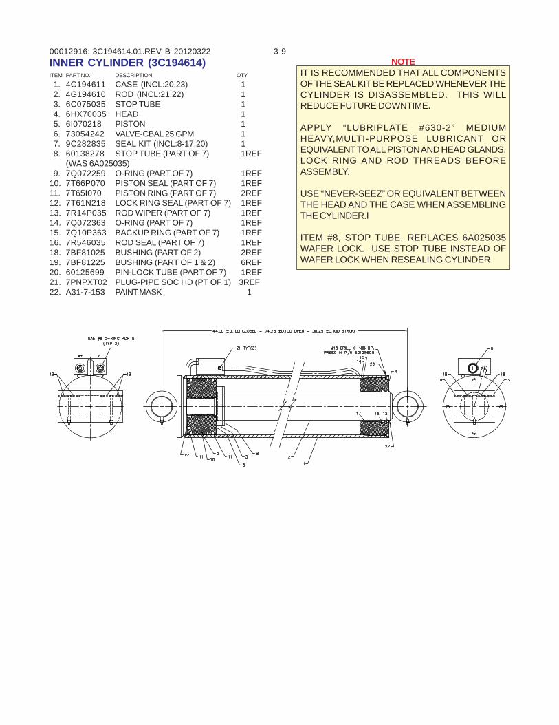
00012916: 3-93C194614.01.REV B 20120322INNER CYLINDER (3C194614)ITEM PART NO. DESCRIPTION QTY
1. 4C194611 CASE (INCL:20,23) 1 2. 4G194610 ROD (INCL:21,22) 1 3. 6C075035 STOP TUBE 1 4. 6HX70035 HEAD 1 5. 6I070218 PISTON 1 6. 73054242 VALVE-CBAL 25 GPM 1 7. 9C282835 SEAL KIT (INCL:8-17,20) 1 8. 60138278 STOP TUBE (PART OF 7) 1REF
(WAS 6A025035) 9. 7Q072259 O-RING (PART OF 7) 1REF10. 7T66P070 PISTON SEAL (PART OF 7) 1REF11. 7T65I070 PISTON RING (PART OF 7) 2REF12. 7T61N218 LOCK RING SEAL (PART OF 7) 1REF13. 7R14P035 ROD WIPER (PART OF 7) 1REF14. 7Q072363 O-RING (PART OF 7) 1REF15. 7Q10P363 BACKUP RING (PART OF 7) 1REF16. 7R546035 ROD SEAL (PART OF 7) 1REF18. 7BF81025 BUSHING (PART OF 2) 2REF19. 7BF81225 BUSHING (PART OF 1 & 2) 6REF20. 60125699 PIN-LOCK TUBE (PART OF 7) 1REF21. 7PNPXT02 PLUG-PIPE SOC HD (PT OF 1) 3REF22. A31-7-153 PAINT MASK 1
NOTEIT IS RECOMMENDED THAT ALL COMPONENTSOF THE SEAL KIT BE REPLACED WHENEVER THECYLINDER IS DISASSEMBLED. THIS WILLREDUCE FUTURE DOWNTIME.
APPLY “LUBRIPLATE #630-2” MEDIUMHEAVY,MULTI-PURPOSE LUBRICANT OREQUIVALENT TO ALL PISTON AND HEAD GLANDS,LOCK RING AND ROD THREADS BEFOREASSEMBLY.
USE “NEVER-SEEZ” OR EQUIVALENT BETWEENTHE HEAD AND THE CASE WHEN ASSEMBLINGTHE CYLINDER.I
ITEM #8, STOP TUBE, REPLACES 6A025035WAFER LOCK. USE STOP TUBE INSTEAD OFWAFER LOCK WHEN RESEALING CYLINDER.
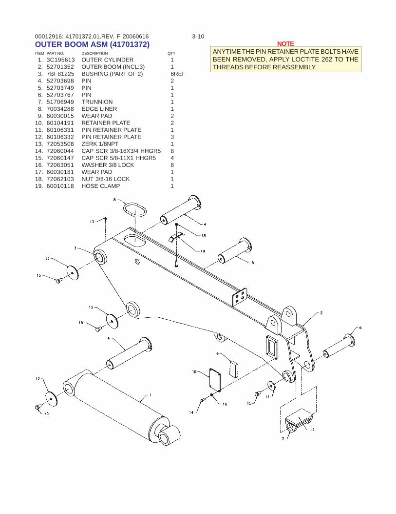
00012916: 3-1041701372.01.REV. F 20060616OUTER BOOM ASM (41701372)ITEM PART NO. DESCRIPTION QTY
1. 3C195613 OUTER CYLINDER 1 2. 52701352 OUTER BOOM (INCL:3) 1 3. 7BF81225 BUSHING (PART OF 2) 6REF 4. 52703698 PIN 2 5. 52703749 PIN 1 6. 52703767 PIN 1 7. 51706949 TRUNNION 1 8. 70034288 EDGE LINER 1 9. 60030015 WEAR PAD 210. 60104191 RETAINER PLATE 211. 60106331 PIN RETAINER PLATE 112. 60106332 PIN RETAINER PLATE 313. 72053508 ZERK 1/8NPT 114. 72060044 CAP SCR 3/8-16X3/4 HHGR5 815. 72060147 CAP SCR 5/8-11X1 HHGR5 416. 72063051 WASHER 3/8 LOCK 817. 60030181 WEAR PAD 118. 72062103 NUT 3/8-16 LOCK 119. 60010118 HOSE CLAMP 1
NOTEANYTIME THE PIN RETAINER PLATE BOLTS HAVEBEEN REMOVED, APPLY LOCTITE 262 TO THETHREADS BEFORE REASSEMBLY.
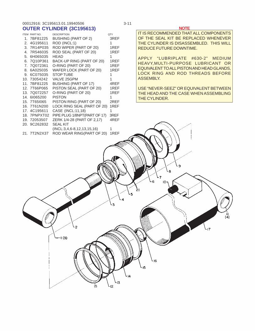
00012916: 3-113C195613.01.19940506OUTER CYLINDER (3C195613)ITEM PART NO. DESCRIPTION QTY
1. 7BF81225 BUSHING (PART OF 2) 3REF 2. 4G195611 ROD (INCL:1) 1 3. 7R14P035 ROD WIPER (PART OF 20) 1REF 4. 7R546035 ROD SEAL (PART OF 20) 1REF 5. 6H065035 HEAD 1 6. 7Q10P361 BACK-UP RING (PART OF 20) 1REF 7. 7Q072361 O-RING (PART OF 20) 1REF 8. 6A025035 WAFER LOCK (PART OF 20) 1REF 9. 6C075035 STOP TUBE 110. 73054242 VALVE 25GPM 111. 7BF81225 BUSHING (PART OF 17) 4REF12. 7T66P065 PISTON SEAL (PART OF 20) 1REF13. 7Q072257 O-RING (PART OF 20) 1REF14. 6I065200 PISTON 115. 7T65I065 PISTON RING (PART OF 20) 2REF16. 7T61N200 LOCK RING SEAL (PART OF 20) 1REF17. 4C195611 CASE (INCL:11,18) 118. 7PNPXT02 PIPE PLUG 1/8NPT(PART OF 17) 3REF19. 72053507 ZERK 1/4-28 (PART OF 2,17) 4REF20. 9C262832 SEAL KIT
(INCL:3,4,6-8,12,13,15,16) 121. 7T2N2X37 ROD WEAR RING(PART OF 20) 1REF
NOTEIT IS RECOMMENDED THAT ALL COMPONENTSOF THE SEAL KIT BE REPLACED WHENEVERTHE CYLINDER IS DISASSEMBLED. THIS WILLREDUCE FUTURE DOWNTIME.
APPLY “LUBRIPLATE #630-2” MEDIUMHEAVY,MULTI-PURPOSE LUBRICANT OREQUIVALENT TO ALL PISTON AND HEAD GLANDS,LOCK RING AND ROD THREADS BEFOREASSEMBLY.
USE “NEVER-SEEZ” OR EQUIVALENT BETWEENTHE HEAD AND THE CASE WHEN ASSEMBLINGTHE CYLINDER.
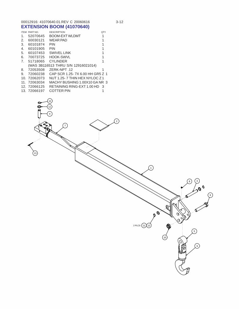
00012916: 3-1241070640.01.REV C 20060616EXTENSION BOOM (41070640)ITEM PART NO. DESCRIPTION QTY
1. 52070645 BOOM-EXT WLDMT 12. 60030121 WEAR PAD 13. 60101874 PIN 14. 60101905 PIN 15. 60107453 SWIVEL LINK 16. 70073725 HOOK-SWVL 17. 51718065 CYLINDER 1
(WAS 3B116513 THRU S/N 12916021014)8. 72053508 ZERK-NPT .12 19. 72060238 CAP SCR 1.25- 7X 6.00 HH GR5 Z 110. 72062073 NUT 1.25- 7 THIN HEX NYLOC Z 111. 72063034 MACHY BUSHING 1.00X10 GA NR 312. 72066125 RETAINING RING-EXT 1.00 HD 313. 72066197 COTTER PIN 1
2
8
9
10
6
3
1211
13
12
11
4
1
2 PLCS
5
7
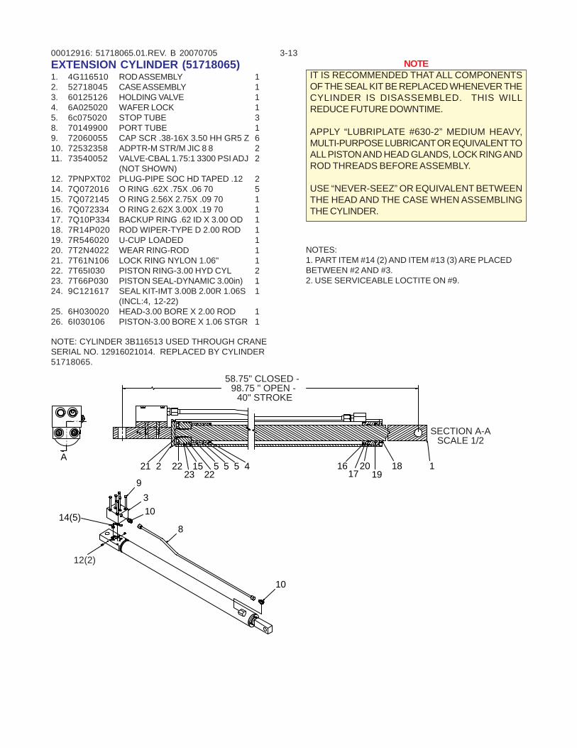
00012916: 3-1351718065.01.REV. B 20070705EXTENSION CYLINDER (51718065)1. 4G116510 ROD ASSEMBLY 12. 52718045 CASE ASSEMBLY 13. 60125126 HOLDING VALVE 14. 6A025020 WAFER LOCK 15. 6c075020 STOP TUBE 38. 70149900 PORT TUBE 19. 72060055 CAP SCR .38-16X 3.50 HH GR5 Z 610. 72532358 ADPTR-M STR/M JIC 8 8 211. 73540052 VALVE-CBAL 1.75:1 3300 PSI ADJ 2
(NOT SHOWN)12. 7PNPXT02 PLUG-PIPE SOC HD TAPED .12 214. 7Q072016 O RING .62X .75X .06 70 515. 7Q072145 O RING 2.56X 2.75X .09 70 116. 7Q072334 O RING 2.62X 3.00X .19 70 117. 7Q10P334 BACKUP RING .62 ID X 3.00 OD 118. 7R14P020 ROD WIPER-TYPE D 2.00 ROD 119. 7R546020 U-CUP LOADED 120. 7T2N4022 WEAR RING-ROD 121. 7T61N106 LOCK RING NYLON 1.06" 122. 7T65I030 PISTON RING-3.00 HYD CYL 223. 7T66P030 PISTON SEAL-DYNAMIC 3.00in) 124. 9C121617 SEAL KIT-IMT 3.00B 2.00R 1.06S 1
(INCL:4, 12-22)25. 6H030020 HEAD-3.00 BORE X 2.00 ROD 126. 6I030106 PISTON-3.00 BORE X 1.06 STGR 1
NOTE: CYLINDER 3B116513 USED THROUGH CRANESERIAL NO. 12916021014. REPLACED BY CYLINDER51718065.
NOTES:1. PART ITEM #14 (2) AND ITEM #13 (3) ARE PLACEDBETWEEN #2 AND #3.2. USE SERVICEABLE LOCTITE ON #9.
A118
192016
1722
2315
225 45 52
39
10
21
10
8
12(2)
14(5)
58.75" CLOSED - 98.75 " OPEN -
40" STROKE
SECTION A-ASCALE 1/2
NOTEIT IS RECOMMENDED THAT ALL COMPONENTSOF THE SEAL KIT BE REPLACED WHENEVER THECYLINDER IS DISASSEMBLED. THIS WILLREDUCE FUTURE DOWNTIME.
APPLY “LUBRIPLATE #630-2” MEDIUM HEAVY,MULTI-PURPOSE LUBRICANT OR EQUIVALENT TOALL PISTON AND HEAD GLANDS, LOCK RING ANDROD THREADS BEFORE ASSEMBLY.
USE “NEVER-SEEZ” OR EQUIVALENT BETWEENTHE HEAD AND THE CASE WHEN ASSEMBLINGTHE CYLINDER.
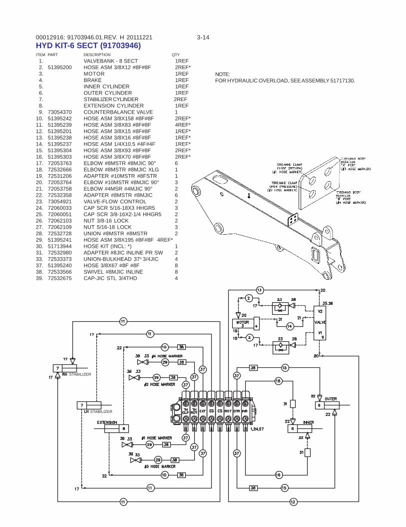
00012916: 3-1491703946.01.REV. H 20111221HYD KIT-6 SECT (91703946)ITEM PART DESCRIPTION QTY 1. VALVEBANK - 8 SECT 1REF 2. 51395200 HOSE ASM 3/8X12 #8F#8F 2REF* 3. MOTOR 1REF 4. BRAKE 1REF 5. INNER CYLINDER 1REF 6. OUTER CYLINDER 1REF 7. STABILIZER CYLINDER 2REF 8. EXTENSION CYLINDER 1REF 9. 73054370 COUNTERBALANCE VALVE 110. 51395242 HOSE ASM 3/8X158 #8F#8F 2REF*11. 51395239 HOSE ASM 3/8X83 #8F#8F 4REF*12. 51395201 HOSE ASM 3/8X15 #8F#8F 1REF*13. 51395238 HOSE ASM 3/8X16 #8F#8F 1REF*14. 51395237 HOSE ASM 1/4X10.5 #4F#4F 1REF*15. 51395304 HOSE ASM 3/8X93 #8F#8F 2REF*16. 51395303 HOSE ASM 3/8X70 #8F#8F 2REF*17. 72053763 ELBOW #8MSTR #8MJIC 90° 618. 72532666 ELBOW #8MSTR #8MJIC XLG 119. 72531206 ADAPTER #10MSTR #8FSTR 120. 72053764 ELBOW #10MSTR #8MJIC 90° 321. 72053758 ELBOW #4MSR #4MJIC 90° 222. 72532358 ADAPTER #8MSTR #8MJIC 623. 73054921 VALVE-FLOW CONTROL 224. 72060033 CAP SCR 5/16-18X3 HHGR5 325. 72060051 CAP SCR 3/8-16X2-1/4 HHGR5 226. 72062103 NUT 3/8-16 LOCK 227. 72062109 NUT 5/16-18 LOCK 328. 72532728 UNION #8MSTR #8MSTR 229. 51395241 HOSE ASM 3/8X195 #8F#8F 4REF*30. 51713944 HOSE KIT (INCL: *) 131. 72532980 ADAPTER #8JIC INLINE PR SW 233. 72533373 UNION-BULKHEAD 37o 3/4JIC 437. 51395240 HOSE 3/8X67 #8F #8F 838. 72533566 SWIVEL #8MJIC INLINE 839. 72532675 CAP-JIC STL 3/4THD 4
STABILIZER
STABILIZER
NOTE:FOR HYDRAULIC OVERLOAD, SEE ASSEMBLY 51717130.
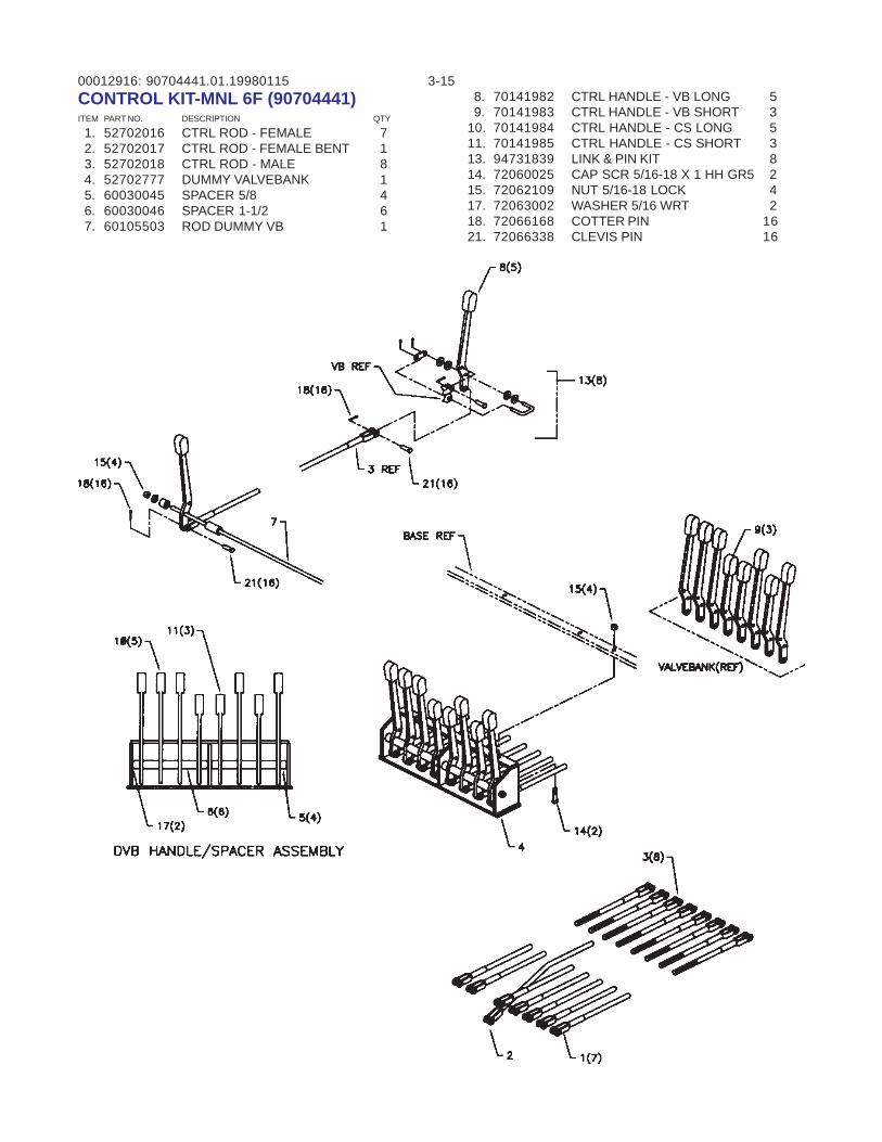
00012916: 3-1590704441.01.19980115CONTROL KIT-MNL 6F (90704441)ITEM PART NO. DESCRIPTION QTY
1. 52702016 CTRL ROD - FEMALE 7 2. 52702017 CTRL ROD - FEMALE BENT 1 3. 52702018 CTRL ROD - MALE 8 4. 52702777 DUMMY VALVEBANK 1 5. 60030045 SPACER 5/8 4 6. 60030046 SPACER 1-1/2 6 7. 60105503 ROD DUMMY VB 1
8. 70141982 CTRL HANDLE - VB LONG 5 9. 70141983 CTRL HANDLE - VB SHORT 310. 70141984 CTRL HANDLE - CS LONG 511. 70141985 CTRL HANDLE - CS SHORT 313. 94731839 LINK & PIN KIT 814. 72060025 CAP SCR 5/16-18 X 1 HH GR5 215. 72062109 NUT 5/16-18 LOCK 417. 72063002 WASHER 5/16 WRT 218. 72066168 COTTER PIN 1621. 72066338 CLEVIS PIN 16
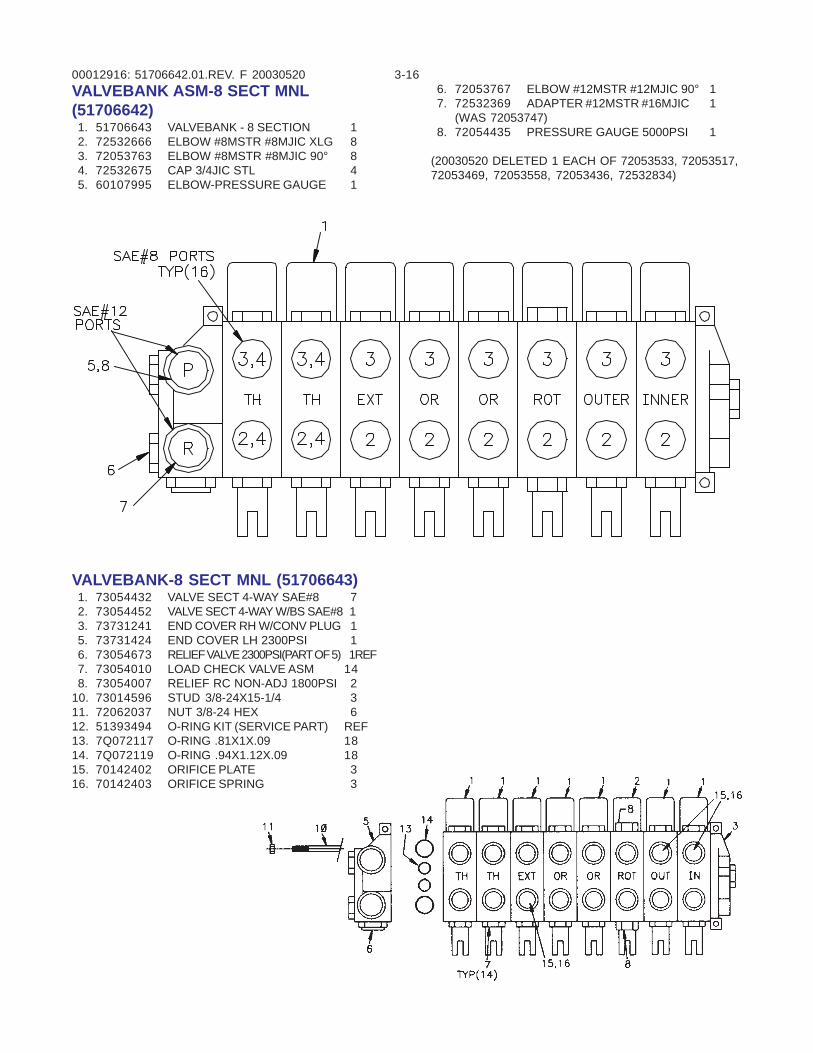
00012916: 3-1651706642.01.REV. F 20030520VALVEBANK ASM-8 SECT MNL(51706642) 1. 51706643 VALVEBANK - 8 SECTION 1 2. 72532666 ELBOW #8MSTR #8MJIC XLG 8 3. 72053763 ELBOW #8MSTR #8MJIC 90° 8 4. 72532675 CAP 3/4JIC STL 4 5. 60107995 ELBOW-PRESSURE GAUGE 1
VALVEBANK-8 SECT MNL (51706643) 1. 73054432 VALVE SECT 4-WAY SAE#8 7 2. 73054452 VALVE SECT 4-WAY W/BS SAE#8 1 3. 73731241 END COVER RH W/CONV PLUG 1 5. 73731424 END COVER LH 2300PSI 1 6. 73054673 RELIEF VALVE 2300PSI(PART OF 5) 1REF 7. 73054010 LOAD CHECK VALVE ASM 14 8. 73054007 RELIEF RC NON-ADJ 1800PSI 210. 73014596 STUD 3/8-24X15-1/4 311. 72062037 NUT 3/8-24 HEX 612. 51393494 O-RING KIT (SERVICE PART) REF13. 7Q072117 O-RING .81X1X.09 1814. 7Q072119 O-RING .94X1.12X.09 1815. 70142402 ORIFICE PLATE 316. 70142403 ORIFICE SPRING 3
6. 72053767 ELBOW #12MSTR #12MJIC 90° 1 7. 72532369 ADAPTER #12MSTR #16MJIC 1
(WAS 72053747) 8. 72054435 PRESSURE GAUGE 5000PSI 1
(20030520 DELETED 1 EACH OF 72053533, 72053517,72053469, 72053558, 72053436, 72532834)
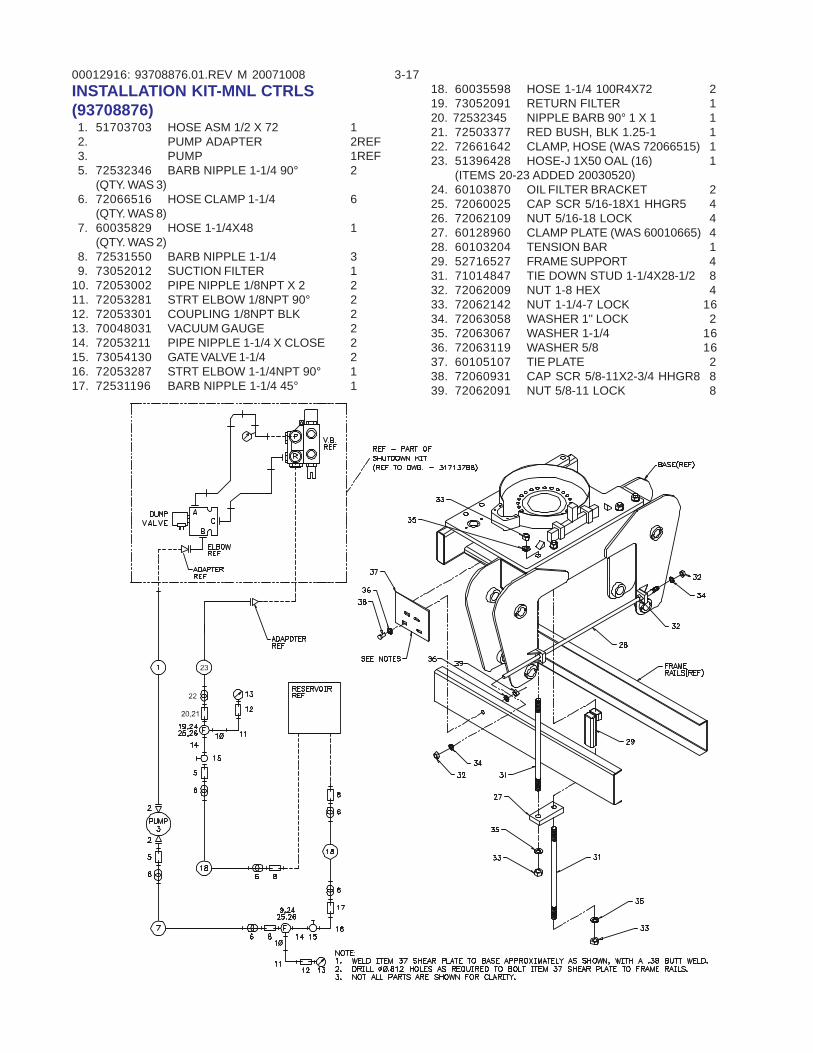
00012916: 3-1793708876.01.REV M 20071008INSTALLATION KIT-MNL CTRLS(93708876) 1. 51703703 HOSE ASM 1/2 X 72 1 2. PUMP ADAPTER 2REF 3. PUMP 1REF 5. 72532346 BARB NIPPLE 1-1/4 90° 2
(QTY. WAS 3) 6. 72066516 HOSE CLAMP 1-1/4 6
(QTY. WAS 8) 7. 60035829 HOSE 1-1/4X48 1
(QTY. WAS 2) 8. 72531550 BARB NIPPLE 1-1/4 3 9. 73052012 SUCTION FILTER 110. 72053002 PIPE NIPPLE 1/8NPT X 2 211. 72053281 STRT ELBOW 1/8NPT 90° 212. 72053301 COUPLING 1/8NPT BLK 213. 70048031 VACUUM GAUGE 214. 72053211 PIPE NIPPLE 1-1/4 X CLOSE 215. 73054130 GATE VALVE 1-1/4 216. 72053287 STRT ELBOW 1-1/4NPT 90° 117. 72531196 BARB NIPPLE 1-1/4 45° 1
18. 60035598 HOSE 1-1/4 100R4X72 219. 73052091 RETURN FILTER 120. 72532345 NIPPLE BARB 90° 1 X 1 121. 72503377 RED BUSH, BLK 1.25-1 122. 72661642 CLAMP, HOSE (WAS 72066515) 123. 51396428 HOSE-J 1X50 OAL (16) 1
(ITEMS 20-23 ADDED 20030520)24. 60103870 OIL FILTER BRACKET 225. 72060025 CAP SCR 5/16-18X1 HHGR5 426. 72062109 NUT 5/16-18 LOCK 427. 60128960 CLAMP PLATE (WAS 60010665) 428. 60103204 TENSION BAR 129. 52716527 FRAME SUPPORT 431. 71014847 TIE DOWN STUD 1-1/4X28-1/2 832. 72062009 NUT 1-8 HEX 433. 72062142 NUT 1-1/4-7 LOCK 1634. 72063058 WASHER 1" LOCK 235. 72063067 WASHER 1-1/4 1636. 72063119 WASHER 5/8 1637. 60105107 TIE PLATE 238. 72060931 CAP SCR 5/8-11X2-3/4 HHGR8 839. 72062091 NUT 5/8-11 LOCK 8
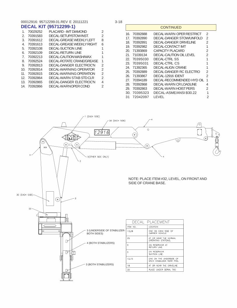
00012916: 3-1895712299.01.REV E 20111221DECAL KIT (95712299-1) 1. 70029252 PLACARD - IMT DIAMOND 2 2. 70391583 DECAL-SETUP/STOW INST. 2 3. 70391612 DECAL-GREASE WEEKLY LEFT 8 4. 70391613 DECAL-GREASE WEEKLY RIGHT 6 5. 70392108 DECAL-SUCTION LINE 1 6. 70392109 DECAL-RETURN LINE 1 7. 70392213 DECAL-CAUTION WASH/WAX 1 8. 70392524 DECAL-ROTATE CRANE/GREASE 1 9. 70392813 DECAL-DANGER ELECTROC’N 210. 70392814 DECAL-WARNING OPERATOR 211. 70392815 DECAL-WARNING OPERATION 212. 70392864 DECAL-WARN STAB STD CLR 213. 70392865 DECAL-DANGER ELECTROC’N 414. 70392866 DECAL-WARNOPER COND 2
16. 70392888 DECAL-WARN OPER RESTRICT 217. 70392890 DECAL-DANGER STOW/UNFOLD 218. 70392891 DECAL-DANGER DRIVELINE 219. 70392982 DECAL-CONTACT IMT 120. 71393869 CAPACITY PLACARD 221. 71039134 DECAL-CAUTION OIL LEVEL 222. 70395030 DECAL-CTRL SS 123. 70395031 DECAL-CTRL CS 124. 71392365 DECAL-ALIGN CRANE 125. 70392889 DECAL-DANGER RC ELECTRO 226. 71393867 DECAL-12916 IDENT 227. 70394189 DECAL-RECOMMENDED HYD OIL 128. 70392868 DECAL-WARN CR LOADLINE 429. 70392863 DECAL-WARN HOIST PERS 230. 70395323 DECAL-ASME/ANSI B30.22 131 72042097 LEVEL 2
CONTINUED
3 (UNDERSIDE OF STABILIZER-BOTH SIDES)
3 (BOTH STABILIZERS)
4 (BOTH STABILIZERS)
STABILIZER
NOTE: PLACE ITEM #32, LEVEL, ON FRONT ANDSIDE OF CRANE BASE.
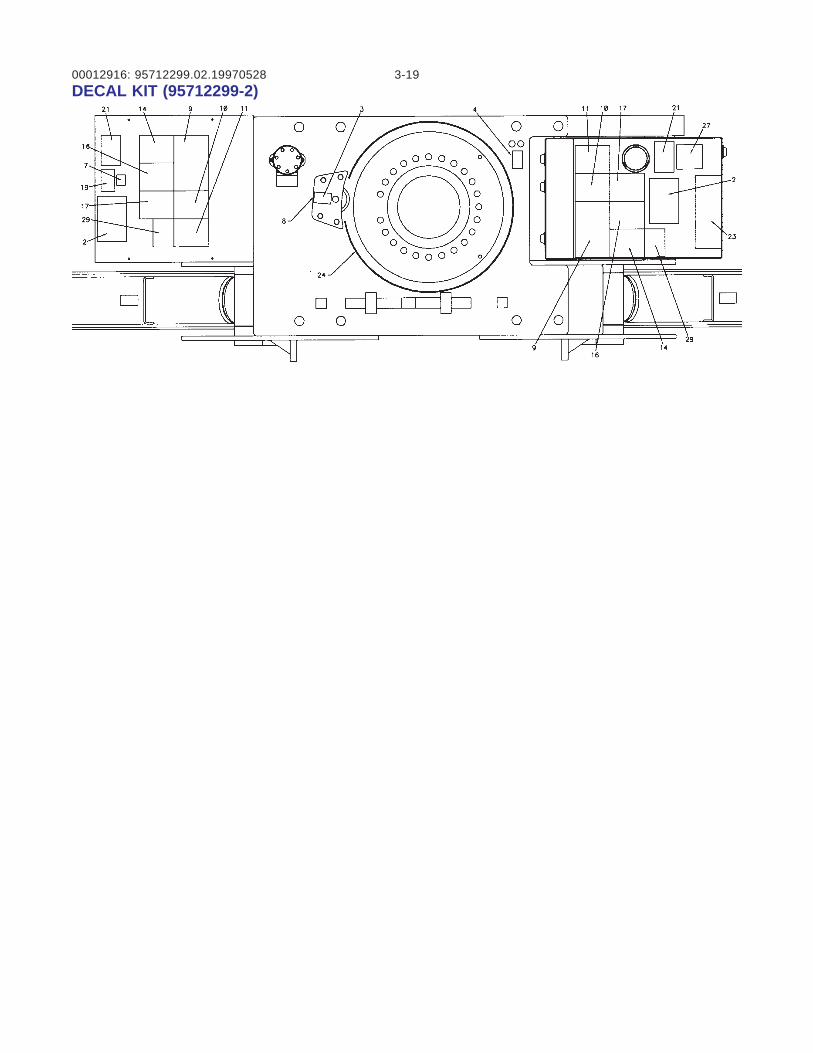
00012916: 3-1995712299.02.19970528DECAL KIT (95712299-2)

00012916: 3-2019980826
(BLANK)
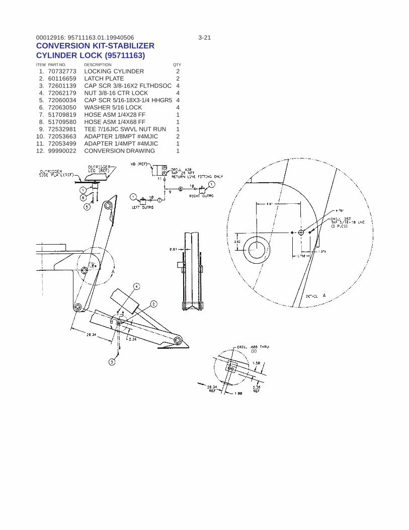
00012916: 3-2195711163.01.19940506CONVERSION KIT-STABILIZERCYLINDER LOCK (95711163)ITEM PART NO. DESCRIPTION QTY
1. 70732773 LOCKING CYLINDER 2 2. 60116659 LATCH PLATE 2 3. 72601139 CAP SCR 3/8-16X2 FLTHDSOC 4 4. 72062179 NUT 3/8-16 CTR LOCK 4 5. 72060034 CAP SCR 5/16-18X3-1/4 HHGR5 4 6. 72063050 WASHER 5/16 LOCK 4 7. 51709819 HOSE ASM 1/4X28 FF 1 8. 51709580 HOSE ASM 1/4X68 FF 1 9. 72532981 TEE 7/16JIC SWVL NUT RUN 110. 72053663 ADAPTER 1/8MPT #4MJIC 211. 72053499 ADAPTER 1/4MPT #4MJIC 112. 99990022 CONVERSION DRAWING 1
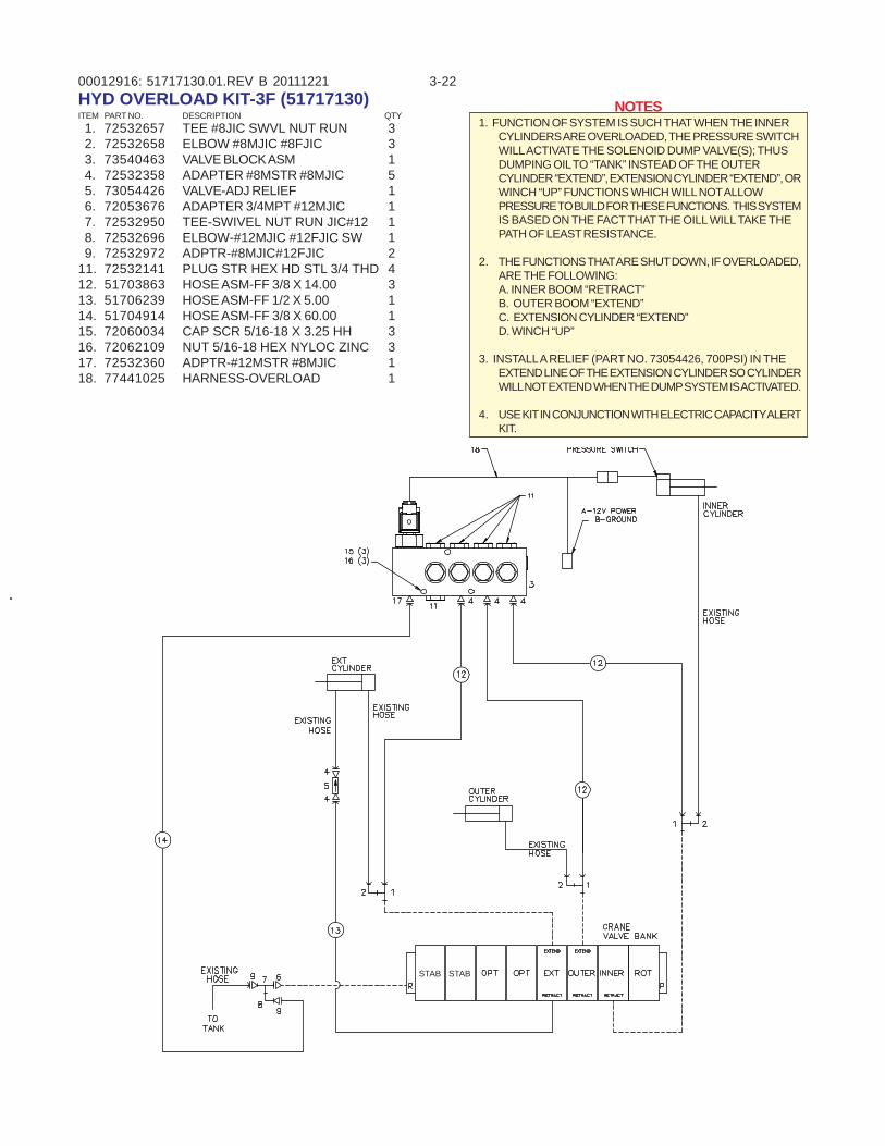
00012916: 3-2251717130.01.REV B 20111221
NOTES1. FUNCTION OF SYSTEM IS SUCH THAT WHEN THE INNER
CYLINDERS ARE OVERLOADED, THE PRESSURE SWITCHWILL ACTIVATE THE SOLENOID DUMP VALVE(S); THUSDUMPING OIL TO “TANK” INSTEAD OF THE OUTERCYLINDER “EXTEND”, EXTENSION CYLINDER “EXTEND”, ORWINCH “UP” FUNCTIONS WHICH WILL NOT ALLOWPRESSURE TO BUILD FOR THESE FUNCTIONS. THIS SYSTEMIS BASED ON THE FACT THAT THE OILL WILL TAKE THEPATH OF LEAST RESISTANCE.
2. THE FUNCTIONS THAT ARE SHUT DOWN, IF OVERLOADED,ARE THE FOLLOWING:A. INNER BOOM “RETRACT”B. OUTER BOOM “EXTEND”C. EXTENSION CYLINDER “EXTEND”D. WINCH “UP”
3. INSTALL A RELIEF (PART NO. 73054426, 700PSI) IN THEEXTEND LINE OF THE EXTENSION CYLINDER SO CYLINDERWILL NOT EXTEND WHEN THE DUMP SYSTEM IS ACTIVATED.
4. USE KIT IN CONJUNCTION WITH ELECTRIC CAPACITY ALERTKIT.
HYD OVERLOAD KIT-3F (51717130)ITEM PART NO. DESCRIPTION QTY 1. 72532657 TEE #8JIC SWVL NUT RUN 3 2. 72532658 ELBOW #8MJIC #8FJIC 3 3. 73540463 VALVE BLOCK ASM 1 4. 72532358 ADAPTER #8MSTR #8MJIC 5 5. 73054426 VALVE-ADJ RELIEF 1 6. 72053676 ADAPTER 3/4MPT #12MJIC 1 7. 72532950 TEE-SWIVEL NUT RUN JIC#12 1 8. 72532696 ELBOW-#12MJIC #12FJIC SW 1 9. 72532972 ADPTR-#8MJIC#12FJIC 211. 72532141 PLUG STR HEX HD STL 3/4 THD 412. 51703863 HOSE ASM-FF 3/8 X 14.00 313. 51706239 HOSE ASM-FF 1/2 X 5.00 114. 51704914 HOSE ASM-FF 3/8 X 60.00 115. 72060034 CAP SCR 5/16-18 X 3.25 HH 316. 72062109 NUT 5/16-18 HEX NYLOC ZINC 317. 72532360 ADPTR-#12MSTR #8MJIC 118. 77441025 HARNESS-OVERLOAD 1
STAB STAB
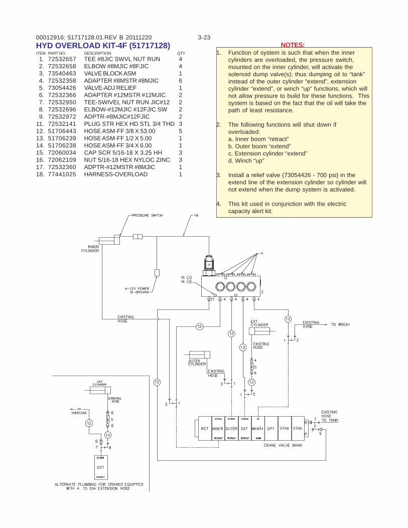
00012916: 3-2351717128.01.REV B 20111220NOTES:
1. Function of system is such that when the innercylinders are overloaded, the pressure switch,mounted on the inner cylinder, will activate thesolenoid dump valve(s); thus dumping oil to “tank”instead of the outer cylinder “extend”, extensioncylinder “extend”, or winch “up” functions, which willnot allow pressure to build for these functions. Thissystem is based on the fact that the oil will take thepath of least resistance.
2. The following functions will shut down ifoverloaded:a. Inner boom “retract”b. Outer boom “extend”c. Extension cylinder “extend”d. Winch “up”
3. Install a relief valve (73054426 - 700 psi) in theextend line of the extension cylinder so cylinder willnot extend when the dump system is activated.
4. This kit used in conjunction with the electriccapacity alert kit.
HYD OVERLOAD KIT-4F (51717128)ITEM PART NO. DESCRIPTION QTY 1. 72532657 TEE #8JIC SWVL NUT RUN 4 2. 72532658 ELBOW #8MJIC #8FJIC 4 3. 73540463 VALVE BLOCK ASM 1 4. 72532358 ADAPTER #8MSTR #8MJIC 6 5. 73054426 VALVE-ADJ RELIEF 1 6. 72532366 ADAPTER #12MSTR #12MJIC 2 7. 72532950 TEE-SWIVEL NUT RUN JIC#12 2 8. 72532696 ELBOW-#12MJIC #12FJIC SW 2 9. 72532972 ADPTR-#8MJIC#12FJIC 211. 72532141 PLUG STR HEX HD STL 3/4 THD 312. 51706443 HOSE ASM-FF 3/8 X 53.00 513. 51706239 HOSE ASM-FF 1/2 X 5.00 114. 51706238 HOSE ASM-FF 3/4 X 6.00 115. 72060034 CAP SCR 5/16-18 X 3.25 HH 316. 72062109 NUT 5/16-18 HEX NYLOC ZINC 317. 72532360 ADPTR-#12MSTR #8MJIC 118. 77441025 HARNESS-OVERLOAD 1
STAB STAB
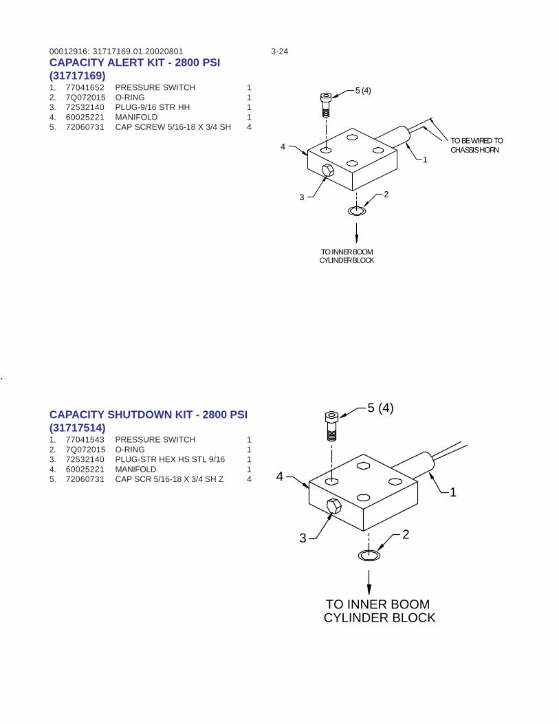
00012916: 3-2431717169.01.20020801CAPACITY ALERT KIT - 2800 PSI(31717169)1. 77041652 PRESSURE SWITCH 12. 7Q072015 O-RING 13. 72532140 PLUG-9/16 STR HH 14. 60025221 MANIFOLD 15. 72060731 CAP SCREW 5/16-18 X 3/4 SH 4
1
23
4
5 (4)
TO INNER BOOMCYLINDER BLOCK
CAPACITY SHUTDOWN KIT - 2800 PSI(31717514)1. 77041543 PRESSURE SWITCH 12. 7Q072015 O-RING 13. 72532140 PLUG-STR HEX HS STL 9/16 14. 60025221 MANIFOLD 15. 72060731 CAP SCR 5/16-18 X 3/4 SH Z 4
TO BE WIRED TOCHASSIS HORN
1
23
4
5 (4)
TO INNER BOOMCYLINDER BLOCK
00012916: 3-25
EFFECTIVE 11/15/02 TO PRESENT
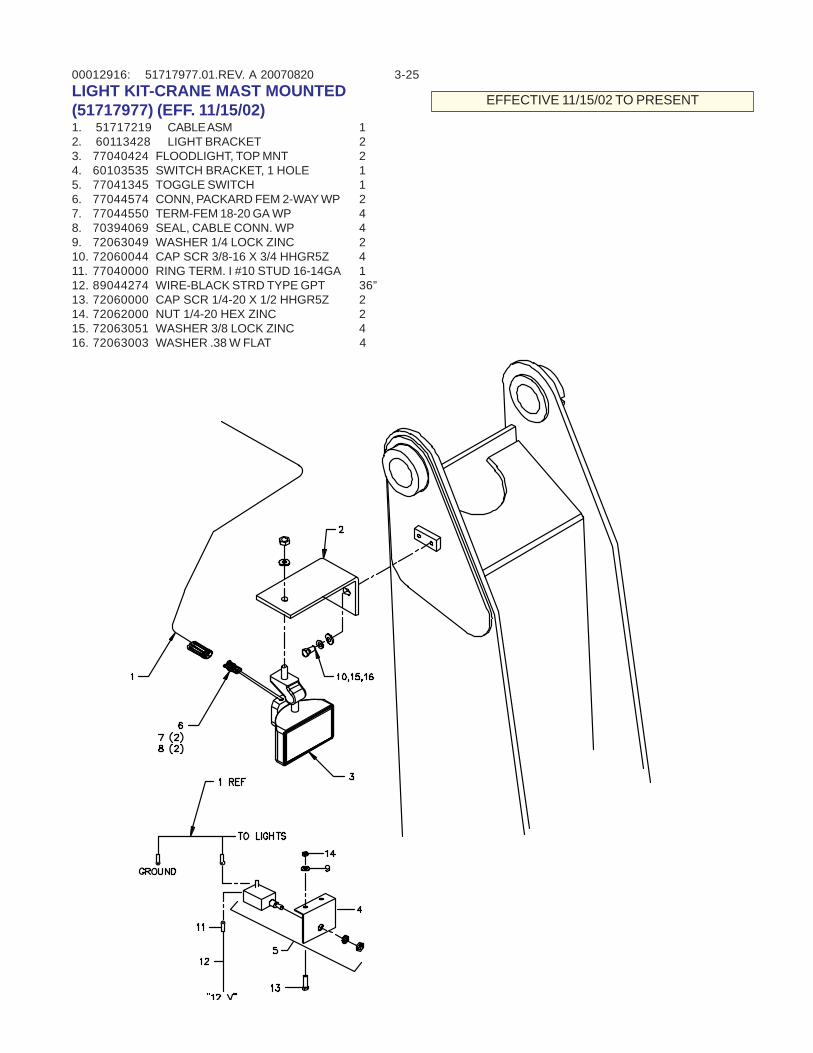
51717977.01.REV. A 20070820LIGHT KIT-CRANE MAST MOUNTED(51717977) (EFF. 11/15/02)1. 51717219 CABLE ASM 12. 60113428 LIGHT BRACKET 23. 77040424 FLOODLIGHT, TOP MNT 24. 60103535 SWITCH BRACKET, 1 HOLE 15. 77041345 TOGGLE SWITCH 16. 77044574 CONN, PACKARD FEM 2-WAY WP 27. 77044550 TERM-FEM 18-20 GA WP 48. 70394069 SEAL, CABLE CONN. WP 49. 72063049 WASHER 1/4 LOCK ZINC 210. 72060044 CAP SCR 3/8-16 X 3/4 HHGR5Z 411. 77040000 RING TERM. I #10 STUD 16-14GA 112. 89044274 WIRE-BLACK STRD TYPE GPT 36”13. 72060000 CAP SCR 1/4-20 X 1/2 HHGR5Z 214. 72062000 NUT 1/4-20 HEX ZINC 215. 72063051 WASHER 3/8 LOCK ZINC 416. 72063003 WASHER .38 W FLAT 4
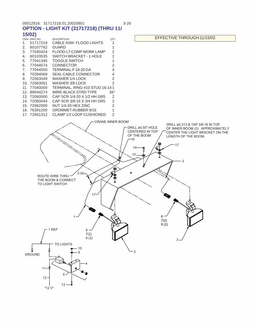
00012916: 3-26OPTION - LIGHT KIT (31717218) (THRU 11/15/02)ITEM PART NO. DESCRIPTION QTY1. 51717219 CABLE ASM- FLOOD LIGHTS 12. 60107762 GUARD 13. 77040424 FLOOD-LT-COMP WORK LAMP 24. 60103535 SWITCH BRACKET - 1 HOLE 15. 77041345 TOGGLE SWITCH 16. 77044574 CONNECTOR 27. 77044550 TERMINAL-F 18-20 GA 48. 70394069 SEAL CABLE CONNECTOR 49. 72063049 WASHER 1/4 LOCK 210. 72063051 WASHER 3/8 LOCK 211. 77040000 TERMINAL, RING #10 STUD 16-14 112. 89044274 WIRE-BLACK STRD TYPE 36”13. 72060000 CAP SCR 1/4-20 X 1/2 HH GR5 214. 72060044 CAP SCR 3/8-16 X 3/4 HH GR5 215. 72062000 NUT 1/4-20 HEX ZINC 216. 76391200 GROMMET-RUBBER 9/16 117. 72661312 CLAMP 1/2 LOOP CUSHIONED 2
31717218.01.20020801
EFFECTIVE THROUGH 11/15/02
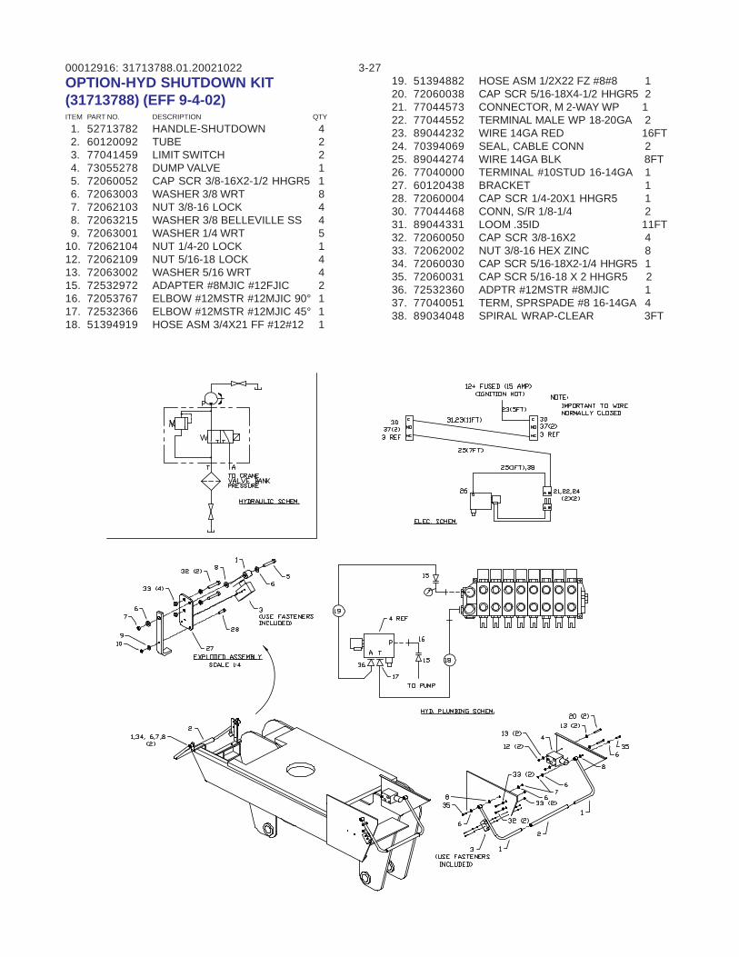
00012916: 3-2731713788.01.20021022OPTION-HYD SHUTDOWN KIT(31713788) (EFF 9-4-02)ITEM PART NO. DESCRIPTION QTY
1. 52713782 HANDLE-SHUTDOWN 4 2. 60120092 TUBE 2 3. 77041459 LIMIT SWITCH 2 4. 73055278 DUMP VALVE 1 5. 72060052 CAP SCR 3/8-16X2-1/2 HHGR5 1 6. 72063003 WASHER 3/8 WRT 8 7. 72062103 NUT 3/8-16 LOCK 4 8. 72063215 WASHER 3/8 BELLEVILLE SS 4 9. 72063001 WASHER 1/4 WRT 510. 72062104 NUT 1/4-20 LOCK 112. 72062109 NUT 5/16-18 LOCK 413. 72063002 WASHER 5/16 WRT 415. 72532972 ADAPTER #8MJIC #12FJIC 216. 72053767 ELBOW #12MSTR #12MJIC 90° 117. 72532366 ELBOW #12MSTR #12MJIC 45° 118. 51394919 HOSE ASM 3/4X21 FF #12#12 1
19. 51394882 HOSE ASM 1/2X22 FZ #8#8 120. 72060038 CAP SCR 5/16-18X4-1/2 HHGR5 221. 77044573 CONNECTOR, M 2-WAY WP 122. 77044552 TERMINAL MALE WP 18-20GA 223. 89044232 WIRE 14GA RED 16FT24. 70394069 SEAL, CABLE CONN 225. 89044274 WIRE 14GA BLK 8FT26. 77040000 TERMINAL #10STUD 16-14GA 127. 60120438 BRACKET 128. 72060004 CAP SCR 1/4-20X1 HHGR5 130. 77044468 CONN, S/R 1/8-1/4 231. 89044331 LOOM .35ID 11FT32. 72060050 CAP SCR 3/8-16X2 433. 72062002 NUT 3/8-16 HEX ZINC 834. 72060030 CAP SCR 5/16-18X2-1/4 HHGR5 135. 72060031 CAP SCR 5/16-18 X 2 HHGR5 236. 72532360 ADPTR #12MSTR #8MJIC 137. 77040051 TERM, SPRSPADE #8 16-14GA 438. 89034048 SPIRAL WRAP-CLEAR 3FT
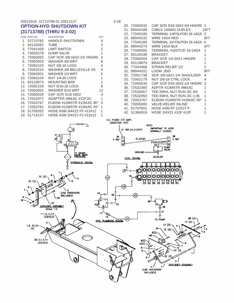
00012916: 3-2831713788.01.20011127OPTION-HYD SHUTDOWN KIT(31713788) (THRU 9-3-02)ITEM PART NO. DESCRIPTION QTY
1. 52713782 HANDLE-SHUTDOWN 4 2. 60120092 TUBE 2 3. 77041459 LIMIT SWITCH 2 4. 73055278 DUMP VALVE 1 5. 72060052 CAP SCR 3/8-16X2-1/2 HHGR5 4 6. 72063003 WASHER 3/8 WRT 8 7. 72062103 NUT 3/8-16 LOCK 4 8. 72063215 WASHER 3/8 BELLEVILLE SS 4 9. 72063001 WASHER 1/4 WRT 510. 72062104 NUT 1/4-20 LOCK 111. 60118873 MOUNTING BAR 112. 72062109 NUT 5/16-18 LOCK 813. 72063002 WASHER 5/16 WRT 1214. 72060029 CAP SCR 5/16-18X2 415. 72532972 ADAPTER #8MJIC #12FJIC 116. 72053767 ELBOW #12MSTR #12MJIC 90° 317. 72053781 ELBOW #12MSTR #12MJIC 45° 118. 51705352 HOSE ASM 3/4X22 FF #12#12 119. 51714157 HOSE ASM 3/4X22 FZ #12#12 1
20. 72060032 CAP SCR 5/16-18X2-3/4 HHGR5 221. 89044188 CABLE 14AWG DUPLEX 15FT22. 77040186 TERMINAL 1/4FSLPON 16-14GA 223. 89044232 WIRE 14GA RED 5FT24. 77040186 TERMINAL 1/4 FSLPON 16-14GA 425. 89044274 WIRE 14GA BLK 1FT26. 77040000 TERMINAL #10STUD 16-14GA 127. 60120438 BRACKET 128. 72060004 CAP SCR 1/4-20X1 HHGR5 129. 60118874 BRACKET 130. 77044468 STRAIN RELIEF 1/2 231. 89044331 LOOM .35ID 9FT32. 72061738 SCR 3/8-16X1-1/4 SHOULDER 433. 72062179 NUT 3/8-16 CTRL LOCK 434. 72060030 CAP SCR 5/16-18X2-1/4 HHGR5 236. 72532360 ADPTR #12MSTR #8MJIC 137. 72532657 TEE-SWVL NUT RUN JIC 3/4 138. 72532950 TEE-SWVL NUT RUN JIC 1.06 139. 72053767 ELBOW #12MSTR #12MJIC 90° 140. 73055000 VALVE-RELIEF INLINE 141. 51707601 HOSE ASM FF 1/2X27 F 142. 51394919 HOSE 3/4X21 #12F #12F 1
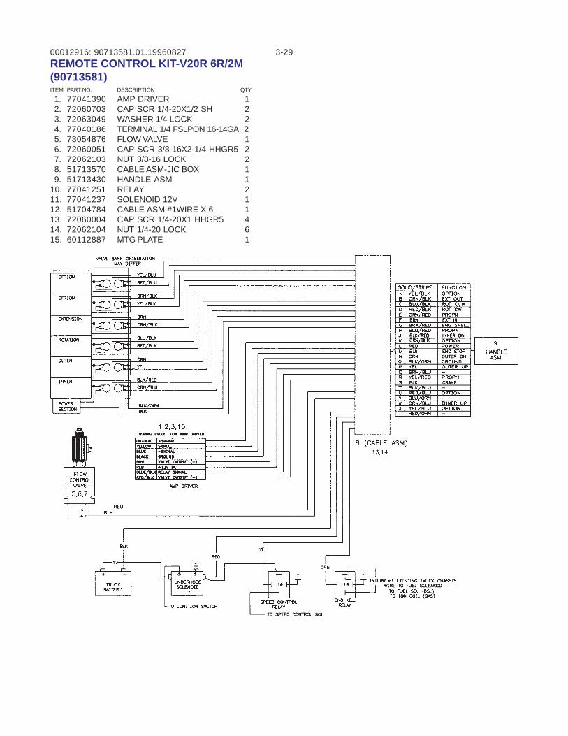
00012916: 3-2990713581.01.19960827REMOTE CONTROL KIT-V20R 6R/2M(90713581)ITEM PART NO. DESCRIPTION QTY
1. 77041390 AMP DRIVER 1 2. 72060703 CAP SCR 1/4-20X1/2 SH 2 3. 72063049 WASHER 1/4 LOCK 2 4. 77040186 TERMINAL 1/4 FSLPON 16-14GA 2 5. 73054876 FLOW VALVE 1 6. 72060051 CAP SCR 3/8-16X2-1/4 HHGR5 2 7. 72062103 NUT 3/8-16 LOCK 2 8. 51713570 CABLE ASM-JIC BOX 1 9. 51713430 HANDLE ASM 110. 77041251 RELAY 211. 77041237 SOLENOID 12V 112. 51704784 CABLE ASM #1WIRE X 6 113. 72060004 CAP SCR 1/4-20X1 HHGR5 414. 72062104 NUT 1/4-20 LOCK 615. 60112887 MTG PLATE 1
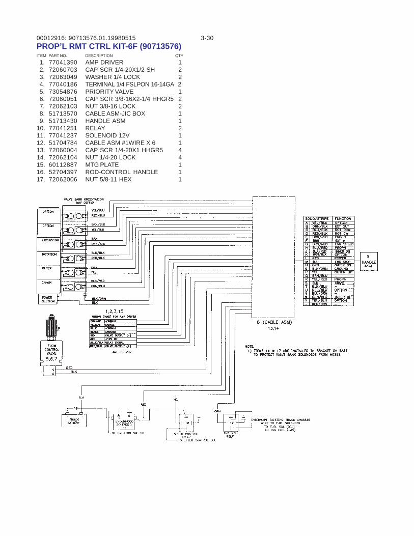
00012916: 3-3090713576.01.19980515PROP’L RMT CTRL KIT-6F (90713576)ITEM PART NO. DESCRIPTION QTY
1. 77041390 AMP DRIVER 1 2. 72060703 CAP SCR 1/4-20X1/2 SH 2 3. 72063049 WASHER 1/4 LOCK 2 4. 77040186 TERMINAL 1/4 FSLPON 16-14GA 2 5. 73054876 PRIORITY VALVE 1 6. 72060051 CAP SCR 3/8-16X2-1/4 HHGR5 2 7. 72062103 NUT 3/8-16 LOCK 2 8. 51713570 CABLE ASM-JIC BOX 1 9. 51713430 HANDLE ASM 110. 77041251 RELAY 211. 77041237 SOLENOID 12V 112. 51704784 CABLE ASM #1WIRE X 6 113. 72060004 CAP SCR 1/4-20X1 HHGR5 414. 72062104 NUT 1/4-20 LOCK 415. 60112887 MTG PLATE 116. 52704397 ROD-CONTROL HANDLE 117. 72062006 NUT 5/8-11 HEX 1
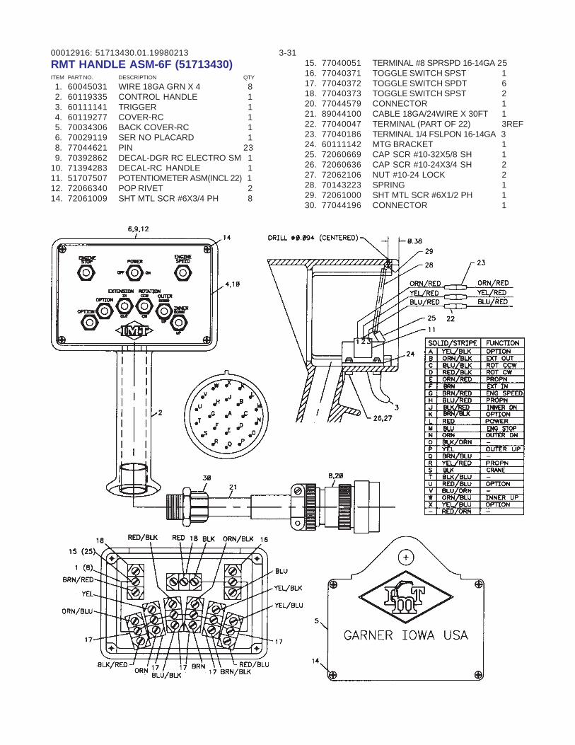
00012916: 3-3151713430.01.19980213RMT HANDLE ASM-6F (51713430)ITEM PART NO. DESCRIPTION QTY
1. 60045031 WIRE 18GA GRN X 4 8 2. 60119335 CONTROL HANDLE 1 3. 60111141 TRIGGER 1 4. 60119277 COVER-RC 1 5. 70034306 BACK COVER-RC 1 6. 70029119 SER NO PLACARD 1 8. 77044621 PIN 23 9. 70392862 DECAL-DGR RC ELECTRO SM 110. 71394283 DECAL-RC HANDLE 111. 51707507 POTENTIOMETER ASM(INCL 22) 112. 72066340 POP RIVET 214. 72061009 SHT MTL SCR #6X3/4 PH 8
15. 77040051 TERMINAL #8 SPRSPD 16-14GA 2516. 77040371 TOGGLE SWITCH SPST 117. 77040372 TOGGLE SWITCH SPDT 618. 77040373 TOGGLE SWITCH SPST 220. 77044579 CONNECTOR 121. 89044100 CABLE 18GA/24WIRE X 30FT 122. 77040047 TERMINAL (PART OF 22) 3REF23. 77040186 TERMINAL 1/4 FSLPON 16-14GA 324. 60111142 MTG BRACKET 125. 72060669 CAP SCR #10-32X5/8 SH 126. 72060636 CAP SCR #10-24X3/4 SH 227. 72062106 NUT #10-24 LOCK 228. 70143223 SPRING 129. 72061000 SHT MTL SCR #6X1/2 PH 130. 77044196 CONNECTOR 1
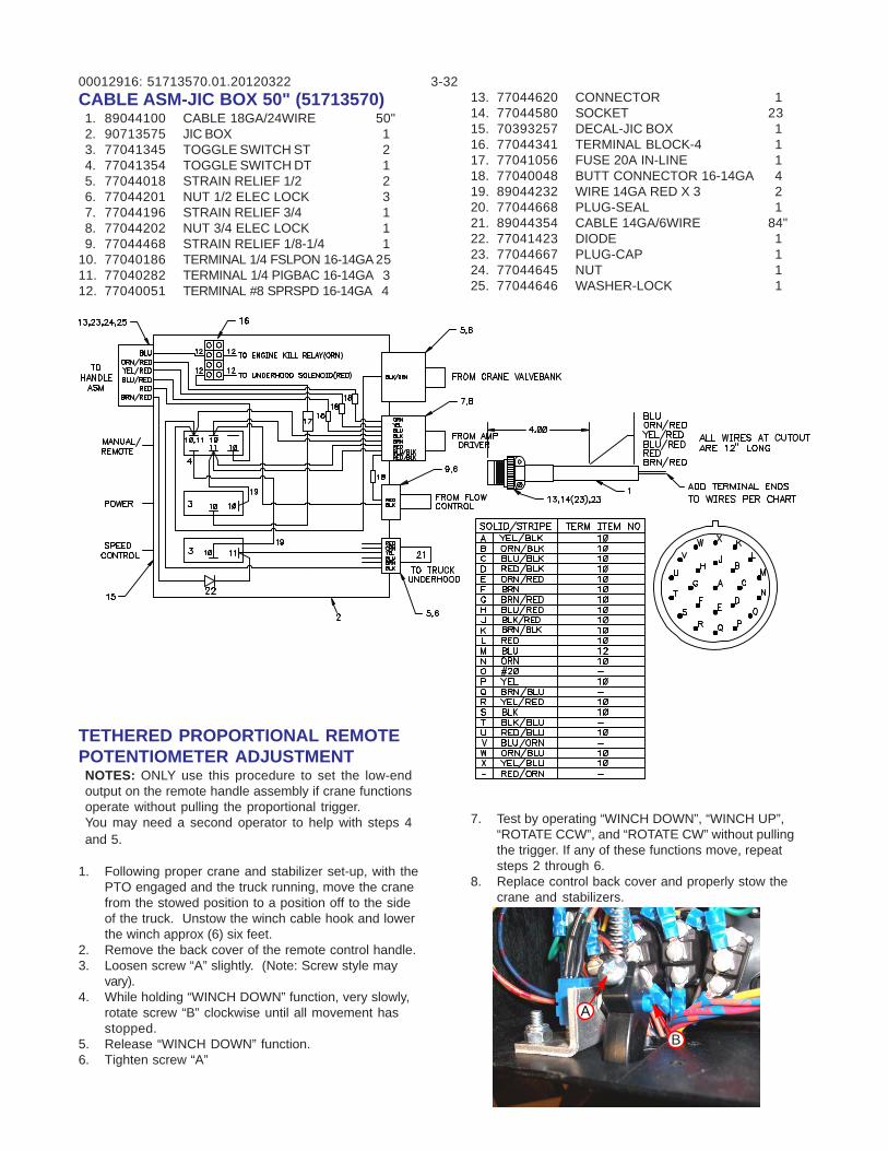
00012916: 3-3251713570.01.20120322CABLE ASM-JIC BOX 50" (51713570) 1. 89044100 CABLE 18GA/24WIRE 50" 2. 90713575 JIC BOX 1 3. 77041345 TOGGLE SWITCH ST 2 4. 77041354 TOGGLE SWITCH DT 1 5. 77044018 STRAIN RELIEF 1/2 2 6. 77044201 NUT 1/2 ELEC LOCK 3 7. 77044196 STRAIN RELIEF 3/4 1 8. 77044202 NUT 3/4 ELEC LOCK 1 9. 77044468 STRAIN RELIEF 1/8-1/4 110. 77040186 TERMINAL 1/4 FSLPON 16-14GA 2511. 77040282 TERMINAL 1/4 PIGBAC 16-14GA 312. 77040051 TERMINAL #8 SPRSPD 16-14GA 4
13. 77044620 CONNECTOR 114. 77044580 SOCKET 2315. 70393257 DECAL-JIC BOX 116. 77044341 TERMINAL BLOCK-4 117. 77041056 FUSE 20A IN-LINE 118. 77040048 BUTT CONNECTOR 16-14GA 419. 89044232 WIRE 14GA RED X 3 220. 77044668 PLUG-SEAL 121. 89044354 CABLE 14GA/6WIRE 84"22. 77041423 DIODE 123. 77044667 PLUG-CAP 124. 77044645 NUT 125. 77044646 WASHER-LOCK 1
TETHERED PROPORTIONAL REMOTEPOTENTIOMETER ADJUSTMENTNOTES: ONLY use this procedure to set the low-endoutput on the remote handle assembly if crane functionsoperate without pulling the proportional trigger.You may need a second operator to help with steps 4and 5.
1. Following proper crane and stabilizer set-up, with thePTO engaged and the truck running, move the cranefrom the stowed position to a position off to the sideof the truck. Unstow the winch cable hook and lowerthe winch approx (6) six feet.
2. Remove the back cover of the remote control handle.3. Loosen screw “A” slightly. (Note: Screw style may
vary).4. While holding “WINCH DOWN” function, very slowly,
rotate screw “B” clockwise until all movement hasstopped.
5. Release “WINCH DOWN” function.6. Tighten screw “A”
7. Test by operating “WINCH DOWN”, “WINCH UP”,“ROTATE CCW”, and “ROTATE CW” without pullingthe trigger. If any of these functions move, repeatsteps 2 through 6.
8. Replace control back cover and properly stow thecrane and stabilizers.
B
A
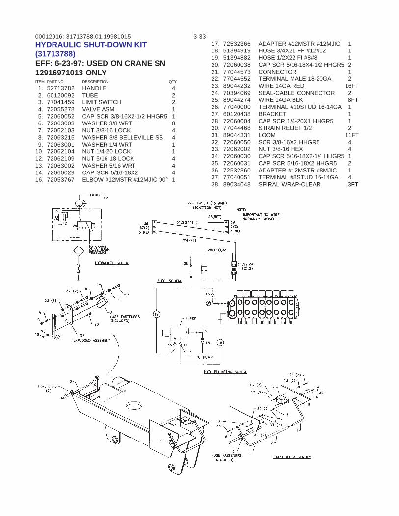
00012916: 3-3331713788.01.19981015HYDRAULIC SHUT-DOWN KIT(31713788)EFF: 6-23-97: USED ON CRANE SN12916971013 ONLYITEM PART NO. DESCRIPTION QTY
1. 52713782 HANDLE 4 2. 60120092 TUBE 2 3. 77041459 LIMIT SWITCH 2 4. 73055278 VALVE ASM 1 5. 72060052 CAP SCR 3/8-16X2-1/2 HHGR5 1 6. 72063003 WASHER 3/8 WRT 8 7. 72062103 NUT 3/8-16 LOCK 4 8. 72063215 WASHER 3/8 BELLEVILLE SS 4 9. 72063001 WASHER 1/4 WRT 110. 72062104 NUT 1/4-20 LOCK 112. 72062109 NUT 5/16-18 LOCK 413. 72063002 WASHER 5/16 WRT 414. 72060029 CAP SCR 5/16-18X2 416. 72053767 ELBOW #12MSTR #12MJIC 90° 1
17. 72532366 ADAPTER #12MSTR #12MJIC 118. 51394919 HOSE 3/4X21 FF #12#12 119. 51394882 HOSE 1/2X22 FI #8#8 120. 72060038 CAP SCR 5/16-18X4-1/2 HHGR5 221. 77044573 CONNECTOR 122. 77044552 TERMINAL MALE 18-20GA 223. 89044232 WIRE 14GA RED 16FT24. 70394069 SEAL-CABLE CONNECTOR 225. 89044274 WIRE 14GA BLK 8FT26. 77040000 TERMINAL #10STUD 16-14GA 127. 60120438 BRACKET 128. 72060004 CAP SCR 1/4-20X1 HHGR5 130. 77044468 STRAIN RELIEF 1/2 231. 89044331 LOOM 11FT32. 72060050 SCR 3/8-16X2 HHGR5 433. 72062002 NUT 3/8-16 HEX 434. 72060030 CAP SCR 5/16-18X2-1/4 HHGR5 135. 72060031 CAP SCR 5/16-18X2 HHGR5 236. 72532360 ADAPTER #12MSTR #8MJIC 137. 77040051 TERMINAL #8STUD 16-14GA 438. 89034048 SPIRAL WRAP-CLEAR 3FT

00012916: 3-34
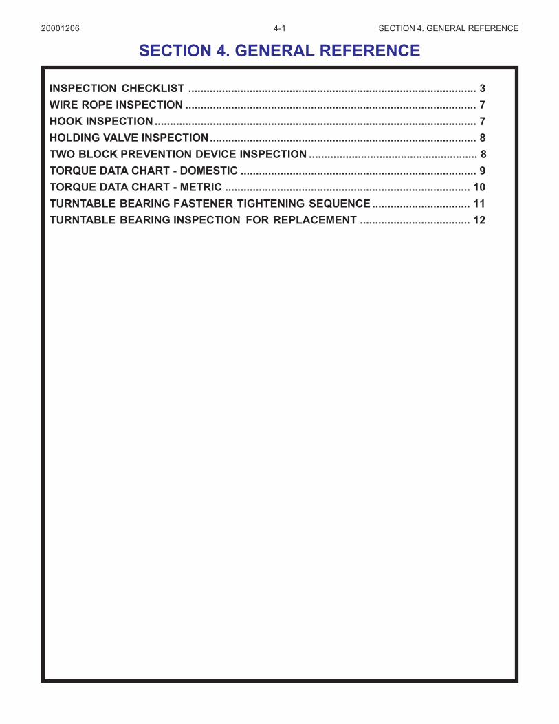
4-1 SECTION 4. GENERAL REFERENCE
INSPECTION CHECKLIST .............................................................................................. 3WIRE ROPE INSPECTION ............................................................................................... 7HOOK INSPECTION ......................................................................................................... 7HOLDING VALVE INSPECTION....................................................................................... 8TWO BLOCK PREVENTION DEVICE INSPECTION ....................................................... 8TORQUE DATA CHART - DOMESTIC ............................................................................. 9TORQUE DATA CHART - METRIC ................................................................................ 10TURNTABLE BEARING FASTENER TIGHTENING SEQUENCE ................................ 11TURNTABLE BEARING INSPECTION FOR REPLACEMENT .................................... 12
SECTION 4. GENERAL REFERENCE20001206

4-2 SECTION 4. GENERAL REFERENCE
NOTES
20000710
4-3 SECTION 4. GENERAL REFERENCE
Inspection Checklist
OWNER/COMPANY
CONTACT PERSON
CRANE MAKE & MODEL
CRANE SERIAL NUMBER
UNIT I.D. NUMBER
LOCATION OF UNIT
CRANES
TYPE OF INSPECTION (check one)
HOUR METER READING (if applicable)
DATE INSPECTED
INSPECTED BY (print)
SIGNATURE OF INSPECTOR
DAILY (if deficiency found)
MONTHLY
QUARTERLY
ANNUAL
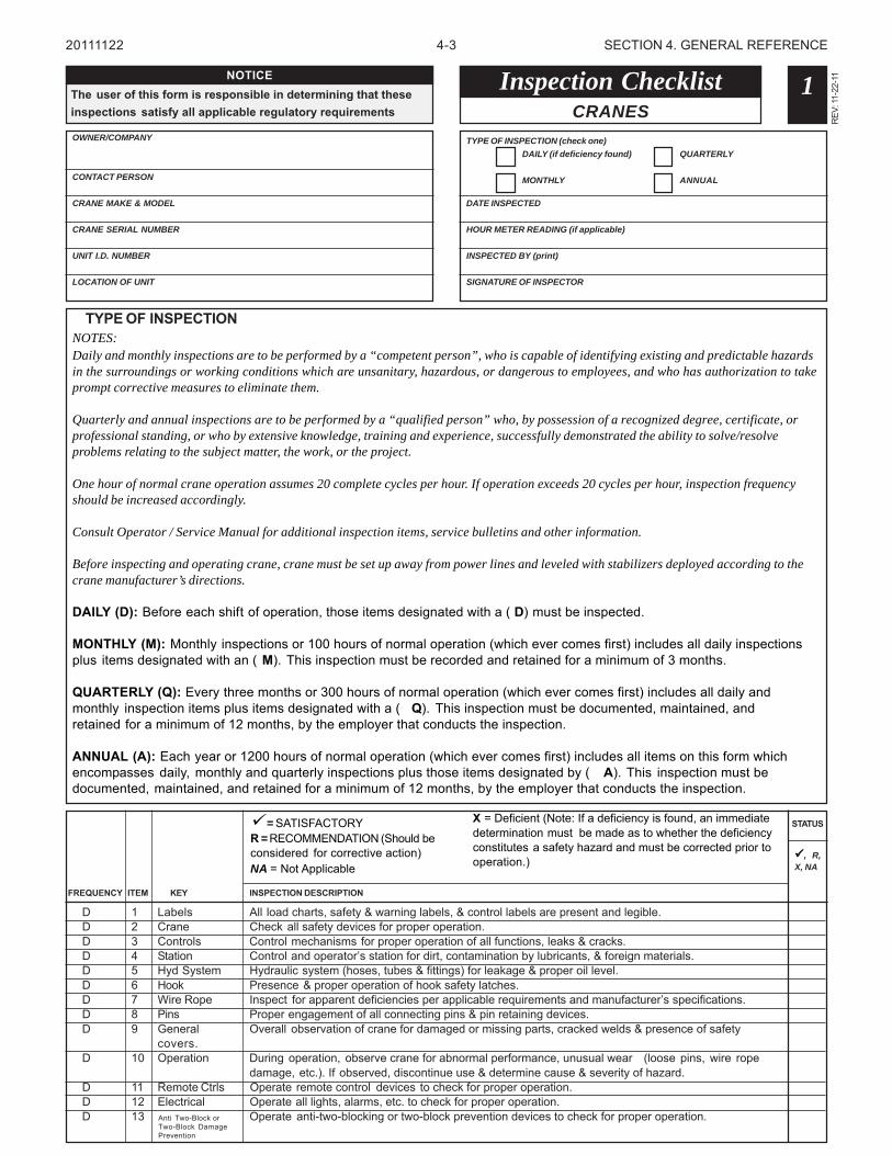
TYPE OF INSPECTIONNOTES:Daily and monthly inspections are to be performed by a “competent person”, who is capable of identifying existing and predictable hazardsin the surroundings or working conditions which are unsanitary, hazardous, or dangerous to employees, and who has authorization to takeprompt corrective measures to eliminate them.
Quarterly and annual inspections are to be performed by a “qualified person” who, by possession of a recognized degree, certificate, orprofessional standing, or who by extensive knowledge, training and experience, successfully demonstrated the ability to solve/resolveproblems relating to the subject matter, the work, or the project.
One hour of normal crane operation assumes 20 complete cycles per hour. If operation exceeds 20 cycles per hour, inspection frequencyshould be increased accordingly.
Consult Operator / Service Manual for additional inspection items, service bulletins and other information.
Before inspecting and operating crane, crane must be set up away from power lines and leveled with stabilizers deployed according to thecrane manufacturer’s directions.
DAILY (D): Before each shift of operation, those items designated with a ( D) must be inspected.
MONTHLY (M): Monthly inspections or 100 hours of normal operation (which ever comes first) includes all daily inspectionsplus items designated with an ( M). This inspection must be recorded and retained for a minimum of 3 months.
QUARTERLY (Q): Every three months or 300 hours of normal operation (which ever comes first) includes all daily andmonthly inspection items plus items designated with a ( Q). This inspection must be documented, maintained, andretained for a minimum of 12 months, by the employer that conducts the inspection.
ANNUAL (A): Each year or 1200 hours of normal operation (which ever comes first) includes all items on this form whichencompasses daily, monthly and quarterly inspections plus those items designated by ( A). This inspection must bedocumented, maintained, and retained for a minimum of 12 months, by the employer that conducts the inspection.
1
REV
: 11-
22-1
1NOTICEThe user of this form is responsible in determining that theseinspections satisfy all applicable regulatory requirements
20111122
D 1 Labels All load charts, safety & warning labels, & control labels are present and legible.D 2 Crane Check all safety devices for proper operation.D 3 Controls Control mechanisms for proper operation of all functions, leaks & cracks.D 4 Station Control and operator’s station for dirt, contamination by lubricants, & foreign materials.D 5 Hyd System Hydraulic system (hoses, tubes & fittings) for leakage & proper oil level.D 6 Hook Presence & proper operation of hook safety latches.D 7 Wire Rope Inspect for apparent deficiencies per applicable requirements and manufacturer’s specifications.D 8 Pins Proper engagement of all connecting pins & pin retaining devices.D 9 General Overall observation of crane for damaged or missing parts, cracked welds & presence of safety
covers.D 10 Operation During operation, observe crane for abnormal performance, unusual wear (loose pins, wire rope
damage, etc.). If observed, discontinue use & determine cause & severity of hazard.D 11 Remote Ctrls Operate remote control devices to check for proper operation.D 12 Electrical Operate all lights, alarms, etc. to check for proper operation.D 13 Operate anti-two-blocking or two-block prevention devices to check for proper operation.
STATUS
FREQUENCY
, R,X, NA
INSPECTION DESCRIPTIONKEYITEM
= SATISFACTORYR = RECOMMENDATION (Should beconsidered for corrective action)NA = Not Applicable
X = Deficient (Note: If a deficiency is found, an immediatedetermination must be made as to whether the deficiencyconstitutes a safety hazard and must be corrected prior tooperation.)
Anti Two-Block orTwo-Block DamagePrevention
4-4 SECTION 4. GENERAL REFERENCE
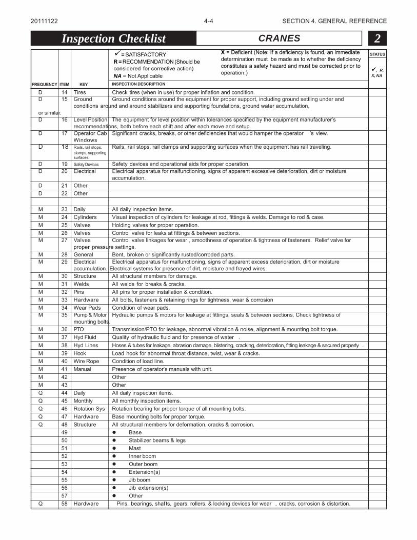
D 14 Tires Check tires (when in use) for proper inflation and condition.D 15 Ground Ground conditions around the equipment for proper support, including ground settling under and
conditions around and around stabilizers and supporting foundations, ground water accumulation,or similar.D 16 Level Position The equipment for level position within tolerances specified by the equipment manufacturer’s
recommendations, both before each shift and after each move and setup.D 17 Operator Cab Significant cracks, breaks, or other deficiencies that would hamper the operator ’s view.
WindowsD 18 Rails, rail stops, Rails, rail stops, rail clamps and supporting surfaces when the equipment has rail traveling.
clamps, supportingsurfaces.
D 19 Safety Devices Safety devices and operational aids for proper operation.D 20 Electrical Electrical apparatus for malfunctioning, signs of apparent excessive deterioration, dirt or moisture
accumulation.D 21 OtherD 22 Other
M 23 Daily All daily inspection items.M 24 Cylinders Visual inspection of cylinders for leakage at rod, fittings & welds. Damage to rod & case.M 25 Valves Holding valves for proper operation.M 26 Valves Control valve for leaks at fittings & between sections.M 27 Valves Control valve linkages for wear , smoothness of operation & tightness of fasteners. Relief valve for
proper pressure settings.M 28 General Bent, broken or significantly rusted/corroded parts.M 29 Electrical Electrical apparatus for malfunctioning, signs of apparent excess deterioration, dirt or moisture
accumulation. Electrical systems for presence of dirt, moisture and frayed wires.M 30 Structure All structural members for damage.M 31 Welds All welds for breaks & cracks.M 32 Pins All pins for proper installation & condition.M 33 Hardware All bolts, fasteners & retaining rings for tightness, wear & corrosionM 34 Wear Pads Condition of wear pads.M 35 Pump & Motor Hydraulic pumps & motors for leakage at fittings, seals & between sections. Check tightness of
mounting bolts.M 36 PTO Transmission/PTO for leakage, abnormal vibration & noise, alignment & mounting bolt torque.M 37 Hyd Fluid Quality of hydraulic fluid and for presence of water .M 38 Hyd Lines Hoses & tubes for leakage, abrasion damage, blistering, cracking, deterioration, fitting leakage & secured properly .M 39 Hook Load hook for abnormal throat distance, twist, wear & cracks.M 40 Wire Rope Condition of load line.M 41 Manual Presence of operator’s manuals with unit.M 42 OtherM 43 OtherQ 44 Daily All daily inspection items.Q 45 Monthly All monthly inspection items.Q 46 Rotation Sys Rotation bearing for proper torque of all mounting bolts.Q 47 Hardware Base mounting bolts for proper torque.Q 48 Structure All structural members for deformation, cracks & corrosion.
49 Base50 Stabilizer beams & legs51 Mast52 Inner boom53 Outer boom54 Extension(s)55 Jib boom56 Jib extension(s)57 Other
Q 58 Hardware Pins, bearings, shaf ts, gears, rollers, & locking devices for wear , cracks, corrosion & distortion.
Inspection Checklist CRANES 2STATUS
FREQUENCY INSPECTION DESCRIPTIONKEYITEM
20111122
, R,X, NA
= SATISFACTORYR = RECOMMENDATION (Should beconsidered for corrective action)NA = Not Applicable
X = Deficient (Note: If a deficiency is found, an immediatedetermination must be made as to whether the deficiencyconstitutes a safety hazard and must be corrected prior tooperation.)
4-5 SECTION 4. GENERAL REFERENCE
STATUS
INSPECTION DESCRIPTIONKEYITEM
Inspection Checklist CRANES 3
20111122
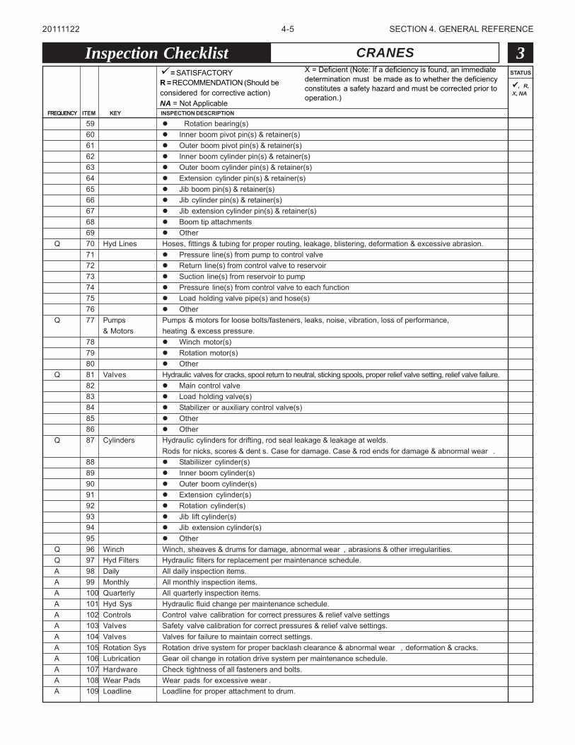
59 Rotation bearing(s)60 Inner boom pivot pin(s) & retainer(s)61 Outer boom pivot pin(s) & retainer(s)62 Inner boom cylinder pin(s) & retainer(s)63 Outer boom cylinder pin(s) & retainer(s)64 Extension cylinder pin(s) & retainer(s)65 Jib boom pin(s) & retainer(s)66 Jib cylinder pin(s) & retainer(s)67 Jib extension cylinder pin(s) & retainer(s)68 Boom tip attachments69 Other
Q 70 Hyd Lines Hoses, fittings & tubing for proper routing, leakage, blistering, deformation & excessive abrasion.71 Pressure line(s) from pump to control valve72 Return line(s) from control valve to reservoir73 Suction line(s) from reservoir to pump74 Pressure line(s) from control valve to each function75 Load holding valve pipe(s) and hose(s)76 Other
Q 77 Pumps Pumps & motors for loose bolts/fasteners, leaks, noise, vibration, loss of performance,& Motors heating & excess pressure.
78 Winch motor(s)79 Rotation motor(s)80 Other
Q 81 Valves Hydraulic valves for cracks, spool return to neutral, sticking spools, proper relief valve setting, relief valve failure.82 Main control valve83 Load holding valve(s)84 Stabilizer or auxiliary control valve(s)85 Other86 Other
Q 87 Cylinders Hydraulic cylinders for drifting, rod seal leakage & leakage at welds.Rods for nicks, scores & dent s. Case for damage. Case & rod ends for damage & abnormal wear .
88 Stabiliizer cylinder(s)89 Inner boom cylinder(s)90 Outer boom cylinder(s)91 Extension cylinder(s)92 Rotation cylinder(s)93 Jib lift cylinder(s)94 Jib extension cylinder(s)95 Other
Q 96 Winch Winch, sheaves & drums for damage, abnormal wear , abrasions & other irregularities.Q 97 Hyd Filters Hydraulic filters for replacement per maintenance schedule.A 98 Daily All daily inspection items.A 99 Monthly All monthly inspection items.A 100 Quarterly All quarterly inspection items.A 101 Hyd Sys Hydraulic fluid change per maintenance schedule.A 102 Controls Control valve calibration for correct pressures & relief valve settingsA 103 Valves Safety valve calibration for correct pressures & relief valve settings.A 104 Valves Valves for failure to maintain correct settings.A 105 Rotation Sys Rotation drive system for proper backlash clearance & abnormal wear , deformation & cracks.A 106 Lubrication Gear oil change in rotation drive system per maintenance schedule.A 107 Hardware Check tightness of all fasteners and bolts.A 108 Wear Pads Wear pads for excessive wear .A 109 Loadline Loadline for proper attachment to drum.
= SATISFACTORYR = RECOMMENDATION (Should beconsidered for corrective action)NA = Not Applicable
X = Deficient (Note: If a deficiency is found, an immediatedetermination must be made as to whether the deficiencyconstitutes a safety hazard and must be corrected prior tooperation.)
FREQUENCY
, R,X, NA
4-6 SECTION 4. GENERAL REFERENCE
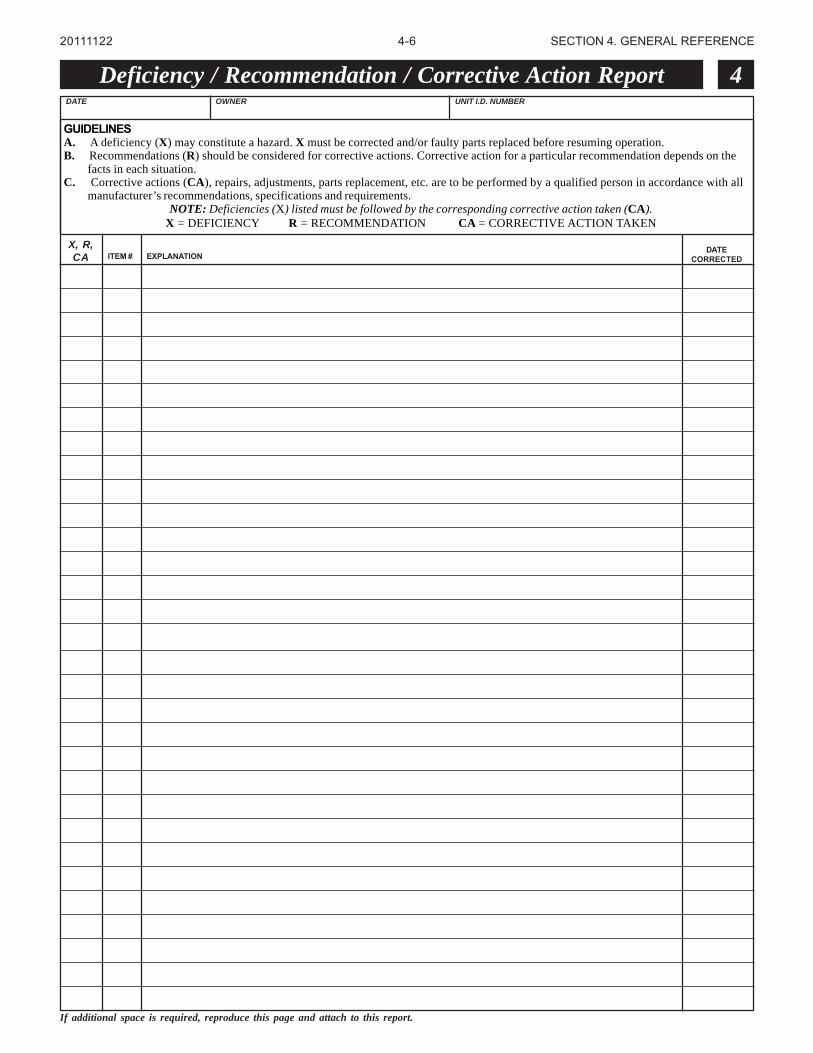
Deficiency / Recommendation / Corrective Action Report 4
X, R,CA ITEM # EXPLANATION
DATECORRECTED
If additional space is required, reproduce this page and attach to this report.
20111122
DATE OWNER UNIT I.D. NUMBER
GUIDELINESA. A deficiency (X) may constitute a hazard. X must be corrected and/or faulty parts replaced before resuming operation.B. Recommendations (R) should be considered for corrective actions. Corrective action for a particular recommendation depends on the
facts in each situation.C. Corrective actions (CA), repairs, adjustments, parts replacement, etc. are to be performed by a qualified person in accordance with all
manufacturer’s recommendations, specifications and requirements.NOTE: Deficiencies (X) listed must be followed by the corresponding corrective action taken (CA).
X = DEFICIENCY R = RECOMMENDATION CA = CORRECTIVE ACTION TAKEN
4-7 SECTION 4. GENERAL REFERENCE
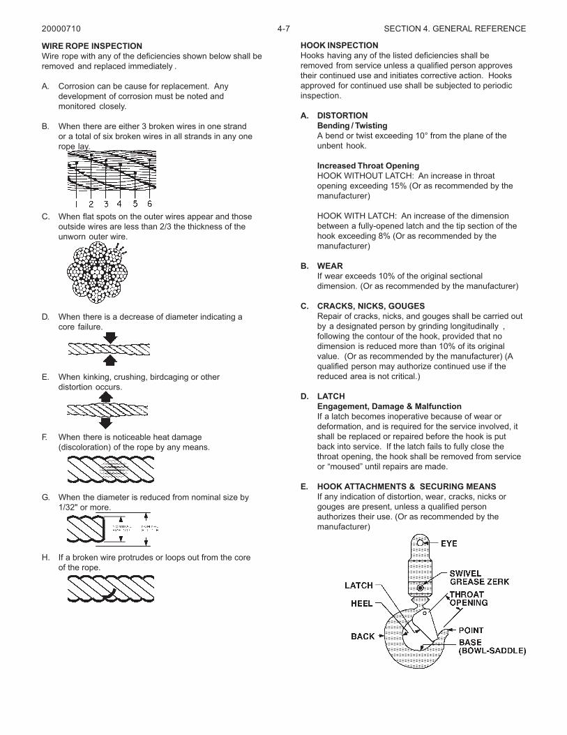
WIRE ROPE INSPECTIONWire rope with any of the deficiencies shown below shall beremoved and replaced immediately .
A. Corrosion can be cause for replacement. Anydevelopment of corrosion must be noted andmonitored closely.
B. When there are either 3 broken wires in one strandor a total of six broken wires in all strands in any onerope lay.
C. When flat spots on the outer wires appear and thoseoutside wires are less than 2/3 the thickness of theunworn outer wire.
D. When there is a decrease of diameter indicating acore failure.
E. When kinking, crushing, birdcaging or otherdistortion occurs.
F. When there is noticeable heat damage(discoloration) of the rope by any means.
G. When the diameter is reduced from nominal size by1/32" or more.
H. If a broken wire protrudes or loops out from the coreof the rope.
HOOK INSPECTIONHooks having any of the listed deficiencies shall beremoved from service unless a qualified person approvestheir continued use and initiates corrective action. Hooksapproved for continued use shall be subjected to periodicinspection.
A. DISTORTIONBending / TwistingA bend or twist exceeding 10° from the plane of theunbent hook.
Increased Throat OpeningHOOK WITHOUT LATCH: An increase in throatopening exceeding 15% (Or as recommended by themanufacturer)
HOOK WITH LATCH: An increase of the dimensionbetween a fully-opened latch and the tip section of thehook exceeding 8% (Or as recommended by themanufacturer)
B. WEARIf wear exceeds 10% of the original sectionaldimension. (Or as recommended by the manufacturer)
C. CRACKS, NICKS, GOUGESRepair of cracks, nicks, and gouges shall be carried outby a designated person by grinding longitudinally ,following the contour of the hook, provided that nodimension is reduced more than 10% of its originalvalue. (Or as recommended by the manufacturer) (Aqualified person may authorize continued use if thereduced area is not critical.)
D. LATCHEngagement, Damage & MalfunctionIf a latch becomes inoperative because of wear ordeformation, and is required for the service involved, itshall be replaced or repaired before the hook is putback into service. If the latch fails to fully close thethroat opening, the hook shall be removed from serviceor “moused” until repairs are made.
E. HOOK ATTACHMENTS & SECURING MEANSIf any indication of distortion, wear, cracks, nicks orgouges are present, unless a qualified personauthorizes their use. (Or as recommended by themanufacturer)
20000710
4-8 SECTION 4. GENERAL REFERENCE
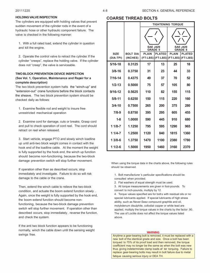
When using the torque data in the charts above, the following rulesshould be observed.
1. Bolt manufacturer ’s particular specifications should beconsulted when provided.2. Flat washers of equal strength must be used.3. All torque measurements are given in foot-pounds. Toconvert to inch-pounds, multiply by 12.4. Torque values specified are for bolt s with residual oils or nospecial lubricants applied. If special lubricants of high stressability, such as Never-Seez compound graphite and oil,molybdenum disulphite, collodial copper or white lead areapplied, multiply the torque values in the charts by the factor .90.The use of Loctite does not affect the torque values listedabove.
WARNINGAnytime a gear-bearing bolt is removed, it must be replaced with anew bolt of the identical grade and size. Once a bolt has beentorqued to 75% of its proof load and then removed, the torquecoefficient may no longer be the same as when the bolt was newthus giving indeterminate clamp loads af ter torquing. Failure toreplace gear-bearing bolts may result in bolt failure due to metalfatique causing serious injury or DEA TH.
5/16-18 0.3125 17 13 25 18
3/8-16 0.3750 31 23 44 33
7/16-14 0.4375 49 37 70 52
1/2-13 0.5000 75 57 105 80
9/16-12 0.5625 110 82 155 115
5/8-11 0.6250 150 115 220 160
3/4-10 0.7500 265 200 375 280
7/8-9 0.8750 395 295 605 455
1-8 1.0000 590 445 910 680
1 1/8-7 1.1250 795 595 1290 965
1 1/4-7 1.2500 1120 840 1815 1360
1 3/8-6 1.3750 1470 1100 2380 1780
1 1/2-6 1.5000 1950 1460 3160 2370
SIZE BOLT DIA PLAIN PLATED PLAIN PLATED(DIA-TPI) (INCHES) (FT-LBS) (FT-LBS) (FT-LBS) (FT-LBS)
SAE J429GRADE 5
SAE J429GRADE 8
TIGHTENING TORQUE
COARSE THREAD BOLTS
20111220
HOLDING VALVE INSPECTIONThe cylinders are equipped with holding valves that preventsudden movement of the cylinder rods in the event of ahydraulic hose or other hydraulic component failure. Thevalve is checked in the following manner:
1. With a full rated load, extend the cylinder in questionand kill the engine.
2. Operate the control valve to retract the cylinder. If thecylinder “creeps”, replace the holding valve. If the cylinderdoes not “creep”, the valve is serviceable.
TWO BLOCK PREVENTION DEVICE INSPECTION(See Vol. 1, Operation, Maintenance and Repair for acomplete description)The two block prevention system halts the “winch-up” and“extension-out” crane functions before the block contactsthe sheave. The two block prevention system should bechecked daily as follows:
1. Examine flexible rod and weight to insure freeunrestricted mechanical operation
2. Examine cord for damage, cuts or breaks. Grasp cordand pull to check operation of cord reel. The cord shouldretract on reel when released.
3. Start vehicle, engage PTO and slowly winch loadlineup until anti-two block weight comes in contact with thehook end of the loadline cable. At the moment the weightis fully supported by the hook end, the winch up functionshould become non-functioning, because the two-blockdamage prevention switch will stop further movement.
If operation other than as described occurs, stopimmediately and investigate. Failure to do so will riskdamage to the cable or the crane.
Then, extend the winch cable to relieve the two-blockcondition, and actuate the boom extend function slowly .Again, once the weight is fully supported by the hook end,the boom extend function should become non-functioning, because the two-block damage preventionswitch will stop further movement. If operation other thandescribed occurs, stop immediately , reverse the function,and check the system.
If the anti two block function appears to be functioningnormally, winch the cable down until the sensing weightswings free.
4-9 SECTION 4. GENERAL REFERENCE
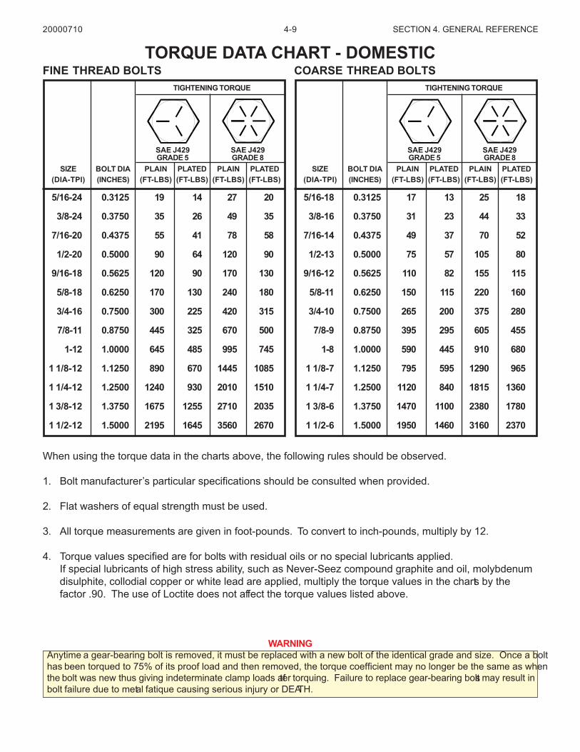
When using the torque data in the charts above, the following rules should be observed.
1. Bolt manufacturer’s particular specifications should be consulted when provided.
2. Flat washers of equal strength must be used.
3. All torque measurements are given in foot-pounds. To convert to inch-pounds, multiply by 12.
4. Torque values specified are for bolts with residual oils or no special lubricants applied.If special lubricants of high stress ability, such as Never-Seez compound graphite and oil, molybdenumdisulphite, collodial copper or white lead are applied, multiply the torque values in the charts by thefactor .90. The use of Loctite does not affect the torque values listed above.
WARNINGAnytime a gear-bearing bolt is removed, it must be replaced with a new bolt of the identical grade and size. Once a bolthas been torqued to 75% of its proof load and then removed, the torque coefficient may no longer be the same as whenthe bolt was new thus giving indeterminate clamp loads after torquing. Failure to replace gear-bearing bolts may result inbolt failure due to metal fatique causing serious injury or DEATH.
TORQUE DATA CHART - DOMESTIC20000710
5/16-24 0.3125 19 14 27 20
3/8-24 0.3750 35 26 49 35
7/16-20 0.4375 55 41 78 58
1/2-20 0.5000 90 64 120 90
9/16-18 0.5625 120 90 170 130
5/8-18 0.6250 170 130 240 180
3/4-16 0.7500 300 225 420 315
7/8-11 0.8750 445 325 670 500
1-12 1.0000 645 485 995 745
1 1/8-12 1.1250 890 670 1445 1085
1 1/4-12 1.2500 1240 930 2010 1510
1 3/8-12 1.3750 1675 1255 2710 2035
1 1/2-12 1.5000 2195 1645 3560 2670
SIZE BOLT DIA PLAIN PLATED PLAIN PLATED(DIA-TPI) (INCHES) (FT-LBS) (FT-LBS) (FT-LBS) (FT-LBS)
SAE J429GRADE 5
SAE J429GRADE 8
TIGHTENING TORQUE
5/16-18 0.3125 17 13 25 18
3/8-16 0.3750 31 23 44 33
7/16-14 0.4375 49 37 70 52
1/2-13 0.5000 75 57 105 80
9/16-12 0.5625 110 82 155 115
5/8-11 0.6250 150 115 220 160
3/4-10 0.7500 265 200 375 280
7/8-9 0.8750 395 295 605 455
1-8 1.0000 590 445 910 680
1 1/8-7 1.1250 795 595 1290 965
1 1/4-7 1.2500 1120 840 1815 1360
1 3/8-6 1.3750 1470 1100 2380 1780
1 1/2-6 1.5000 1950 1460 3160 2370
SIZE BOLT DIA PLAIN PLATED PLAIN PLATED(DIA-TPI) (INCHES) (FT-LBS) (FT-LBS) (FT-LBS) (FT-LBS)
SAE J429GRADE 5
SAE J429GRADE 8
TIGHTENING TORQUE
FINE THREAD BOLTS COARSE THREAD BOLTS
4-10 SECTION 4. GENERAL REFERENCE
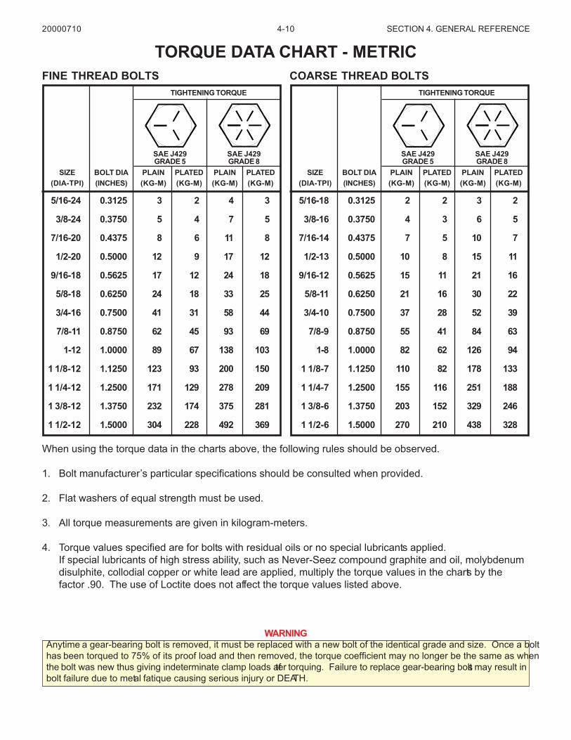
When using the torque data in the charts above, the following rules should be observed.
1. Bolt manufacturer’s particular specifications should be consulted when provided.
2. Flat washers of equal strength must be used.
3. All torque measurements are given in kilogram-meters.
4. Torque values specified are for bolts with residual oils or no special lubricants applied.If special lubricants of high stress ability, such as Never-Seez compound graphite and oil, molybdenumdisulphite, collodial copper or white lead are applied, multiply the torque values in the charts by thefactor .90. The use of Loctite does not affect the torque values listed above.
WARNINGAnytime a gear-bearing bolt is removed, it must be replaced with a new bolt of the identical grade and size. Once a bolthas been torqued to 75% of its proof load and then removed, the torque coefficient may no longer be the same as whenthe bolt was new thus giving indeterminate clamp loads after torquing. Failure to replace gear-bearing bolts may result inbolt failure due to metal fatique causing serious injury or DEATH.
TORQUE DATA CHART - METRIC20000710
5/16-24 0.3125 3 2 4 3
3/8-24 0.3750 5 4 7 5
7/16-20 0.4375 8 6 11 8
1/2-20 0.5000 12 9 17 12
9/16-18 0.5625 17 12 24 18
5/8-18 0.6250 24 18 33 25
3/4-16 0.7500 41 31 58 44
7/8-11 0.8750 62 45 93 69
1-12 1.0000 89 67 138 103
1 1/8-12 1.1250 123 93 200 150
1 1/4-12 1.2500 171 129 278 209
1 3/8-12 1.3750 232 174 375 281
1 1/2-12 1.5000 304 228 492 369
SIZE BOLT DIA PLAIN PLATED PLAIN PLATED(DIA-TPI) (INCHES) (KG-M) (KG-M) (KG-M) (KG-M)
SAE J429GRADE 5
SAE J429GRADE 8
TIGHTENING TORQUE
5/16-18 0.3125 2 2 3 2
3/8-16 0.3750 4 3 6 5
7/16-14 0.4375 7 5 10 7
1/2-13 0.5000 10 8 15 11
9/16-12 0.5625 15 11 21 16
5/8-11 0.6250 21 16 30 22
3/4-10 0.7500 37 28 52 39
7/8-9 0.8750 55 41 84 63
1-8 1.0000 82 62 126 94
1 1/8-7 1.1250 110 82 178 133
1 1/4-7 1.2500 155 116 251 188
1 3/8-6 1.3750 203 152 329 246
1 1/2-6 1.5000 270 210 438 328
SIZE BOLT DIA PLAIN PLATED PLAIN PLATED(DIA-TPI) (INCHES) (KG-M) (KG-M) (KG-M) (KG-M)
SAE J429GRADE 5
SAE J429GRADE 8
TIGHTENING TORQUE
FINE THREAD BOLTS COARSE THREAD BOLTS
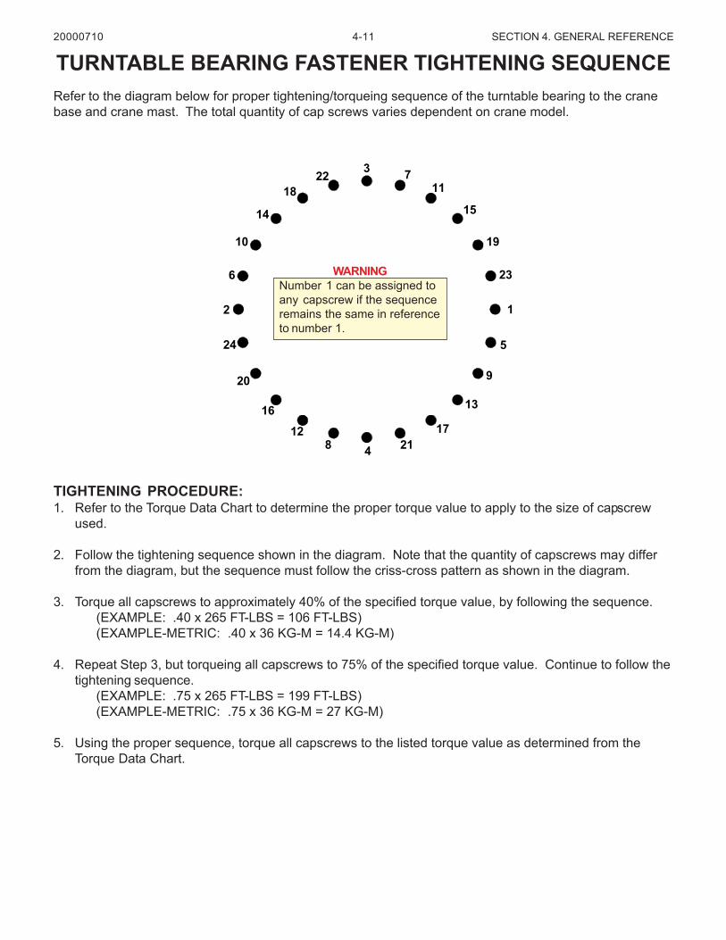
4-11 SECTION 4. GENERAL REFERENCE
TIGHTENING PROCEDURE:1. Refer to the Torque Data Chart to determine the proper torque value to apply to the size of capscrew
used.
2. Follow the tightening sequence shown in the diagram. Note that the quantity of capscrews may differfrom the diagram, but the sequence must follow the criss-cross pattern as shown in the diagram.
3. Torque all capscrews to approximately 40% of the specified torque value, by following the sequence.(EXAMPLE: .40 x 265 FT-LBS = 106 FT-LBS)(EXAMPLE-METRIC: .40 x 36 KG-M = 14.4 KG-M)
4. Repeat Step 3, but torqueing all capscrews to 75% of the specified torque value. Continue to follow thetightening sequence.
(EXAMPLE: .75 x 265 FT-LBS = 199 FT-LBS)(EXAMPLE-METRIC: .75 x 36 KG-M = 27 KG-M)
5. Using the proper sequence, torque all capscrews to the listed torque value as determined from theTorque Data Chart.
TURNTABLE BEARING FASTENER TIGHTENING SEQUENCERefer to the diagram below for proper tightening/torqueing sequence of the turntable bearing to the cranebase and crane mast. The total quantity of cap screws varies dependent on crane model.
WARNINGNumber 1 can be assigned toany capscrew if the sequenceremains the same in referenceto number 1.
20000710
3 711
15
19
23
1
5
9
13
172148
12
16
20
24
2
6
10
14
1822
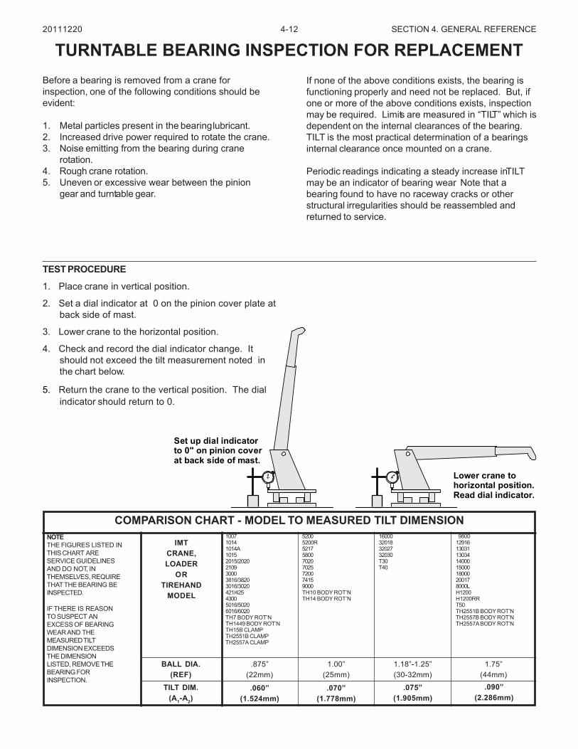
4-12 SECTION 4. GENERAL REFERENCE
Before a bearing is removed from a crane forinspection, one of the following conditions should beevident:
1. Metal particles present in the bearinglubricant.2. Increased drive power required to rotate the crane.3. Noise emitting from the bearing during crane
rotation.4. Rough crane rotation.5. Uneven or excessive wear between the pinion
gear and turntable gear.
TURNTABLE BEARING INSPECTION FOR REPLACEMENTIf none of the above conditions exists, the bearing isfunctioning properly and need not be replaced. But, ifone or more of the above conditions exists, inspectionmay be required. Limits are measured in “TILT” which isdependent on the internal clearances of the bearing.TILT is the most practical determination of a bearingsinternal clearance once mounted on a crane.
Periodic readings indicating a steady increase in TILTmay be an indicator of bearing wear. Note that abearing found to have no raceway cracks or otherstructural irregularities should be reassembled andreturned to service.
NOTETHE FIGURES LISTED INTHIS CHART ARESERVICE GUIDELINESAND DO NOT, INTHEMSELVES, REQUIRETHAT THE BEARING BEINSPECTED.
IF THERE IS REASONTO SUSPECT ANEXCESS OF BEARINGWEAR AND THEMEASURED TILTDIMENSION EXCEEDSTHE DIMENSIONLISTED, REMOVE THEBEARING FORINSPECTION.
IMTCRANE,LOADER
ORTIREHAND
MODEL
BALL DIA.(REF)
TILT DIM.(A1-A2)
.060”(1.524mm)
.070”(1.778mm)
.075”(1.905mm)
.090”(2.286mm)
.875”(22mm)
1.00”(25mm)
1.18”-1.25”(30-32mm)
1.75”(44mm)
100710141014A10152015/2020210930003816/38203016/3020421/42543005016/50206016/6020TH7 BODY ROT’NTH1449 BODY ROT’NTH15B CLAMPTH2551B CLAMPTH2557A CLAMP
52005200R5217580070207025720074159000TH10 BODY ROT’NTH14 BODY ROT’N
16000320183202732030T30T40
9800129161303113034140001500018000200178000LH1200H1200RRT50TH2551B BODY ROT’NTH2557B BODY ROT’NTH2557A BODY ROT’N
COMPARISON CHART - MODEL TO MEASURED TILT DIMENSION
20111220
TEST PROCEDURE
1. Place crane in vertical position.
2. Set a dial indicator at 0 on the pinion cover plate atback side of mast.
3. Lower crane to the horizontal position.
4. Check and record the dial indicator change. Itshould not exceed the tilt measurement noted inthe chart below.
5. Return the crane to the vertical position. The dialindicator should return to 0.
Set up dial indicatorto 0" on pinion coverat back side of mast.
Lower crane tohorizontal position.Read dial indicator.
4-13 SECTION 4. GENERAL REFERENCE
The information within this manual has been compiled and checked but errors do occur. To provide our customers with amethod of communicating those errors we have provided the Manual Change Request form below. In addition to errorreporting, you are encouraged to suggest changes or additions to the manual which would be of benefit to you. Wecannot guarantee that these additions will be made but we do promise to consider them. When completing the form,please write or print clearly. Submit a copy of the completed form to the address listed below.
MANUAL CHANGE REQUEST
MAIL TO:
IOWA MOLD TOOLING CO., INC.BOX 189
GARNER, IA 50438-0189ATTN: Technical Publications
20000710
DATE PRODUCTMANUAL
MANUALPART NO.
SUBMITTED BY
COMPANY
ADDRESS
CITY, STATE, ZIP
TELEPHONE
ERROR FOUND
LOCATION OF ERROR (page no.):
DESCRIPTION OF ERROR:
ERROR FOUND
DESCRIPTION OF ADDITION:
REASON FOR ADDITION:
4-14 SECTION 4. GENERAL REFERENCE
This parts manual is provided to the user to assist in servicing the equipment. It is the property of Iowa Mold T ooling Co., Inc. and,as such, may not be reproduced either whole or in part, whether by chemical, electrostatic, mechanical or photographic meanswithout the expressed written permission of an of ficer of Iowa Mold Tooling Co., Inc. One manual is provided with each piece o fnew equipment and additional manuals may be obt ained at a nominal price. Your distributor may have access to this manualthrough the IMT web site at www.IMT.com.
IOWA MOLD TOOLING CO., INC.BOX 189, GARNER, IA 50438-0189
TEL: 641-923-3711TECHNICAL SUPPORT FAX: 641-923-2424
www.imt.com
20001206