Embed Size (px)
Citation preview

12V ELECTRIC WINCH
12 ,000 LBS.
OWNER’S MANUAL
WARNING:
Read carefully and understand all INSTRUCTIONS before operating. Failure to follow the safety rules and other basic
safety precautions may result in serious personal injury.
Item# 141456

Page of 15 2
For technical questions and replacement parts, please call 1-800-222-5381.
Thank you very much for choosing a NORTHERN TOOL + EQUIPMENT CO., INC. Product! For
future reference, please complete the owner’s record below:
Model: _______________ Purchase Date: _______________
Save the receipt, warranty and these instructions. It is important that you read the entire manual to
become familiar with this product before you begin using it.
This winch is designed for certain applications only. The distributor strongly recommends this winch not be modified and/or used for any application other than that for which it was designed. If you have any questions relative to a particular application, DO NOT use the winch until you have first contacted the distributor to determine if it can or should be performed on the product.
INTENDED USE
This winch is designed for a number of applications, including vehicle rescue.
TECHNICAL SPECIFICATIONS
Description Specifications Rated Line Pull: 12,000 lbs. (5440kgs) single-line Motor 5.5 HP /12V, Series Wound Control: Remote Swich,12ft. (3.7m) lead Gear Train 3-Stage Planetary Gear Ratio 265:1 Clutch Sliding Ring Gear Brake Automatic In-The-Drum Drum Size Diameter: 2.52in. (64mm); Length: 8.82in. (224mm) Wire Rope 93.5ft.L x 23/64in. dia. (28.5m x 9.2mm) Fairlead 4-Way Roller Fairlead Remote Control Included Recommended Battery
650CCA minimum for winching
Battery Leads 72ft. (1.83m) x 25mm2 Finished Black Overall dimensions 21.3in.L x 6.3in.W x 8.6in.H (541 x160 x 218mm ) Mounting Bolt Pattern
10in. x 4.5in. (254 x 114.3mm)
Line Speed & Amp Draw(First layer)
Lbs 2000 4000 6000 8000 10000 12000 Line pull
Kgs NO LOAD
907 1814 2722 3629 4532 5440 Ft/min 23.5 12.8 10.5 9.4 7.4 6.3 5
Line speed m/min 7.2 3.9 3.2 2.9 2.3 1.9 1.5
Motor current
Amps 65 120 165 215 270 320 370
Line Pull & Cable Capacity
Layer of Cable 1 2 3 4
Lbs 12000 10270 9200 8500 Rated Line Pull per Layer Kgs 5440 4654 4169 3852
Ft 16 42 72 94 Cable capacity per layer mpa 5 12 21 28

Page of 15 3
GENERAL SAFETY RULES
WARNING: Read and understand all instructions. Failure to follow all instructions listed
below may result in electric shock, fire and/or serious injury.
WARNING: The warnings, cautions, and instructions discussed in this instruction
manual cannot cover all possible conditions or situations that could occur. It must be
understood by the operator that common sense and caution are factors which cannot be
built into this product, but must be supplied by the operator.
WARNING: DO NOT ATTEMPT TO INSTALL WIRING WHEN THE BATTERY IS
CONNECTED! Automotive and power sports batteries contain flammable and explosive gases.
Wear eye protection during installation and remove all metal jewelry. Do not lean over battery while
making connections.
SAVE THESE INSTRUCTIONS
WINCH USE & SAFETY
WARNING: MOVING PARTS ENTANGLEMENT HAZARD. Failure to observe these
instructions could lead to severe injury or death.
Always keep hands clear of wire rope, hook loop, hook and fairlead opening during installation,
operation, and when spooling in or out.
Always use extreme caution when handling hook and wire rope during spooling operations.
Always wear heavy leather gloves when handling a wire rope, and never let wire rope slip
through your hands.

Page of 15 4
Always stand clear of wire rope and load during operation, and keep bystanders away as well.
Do not try to guide the cable
Always be certain the anchor you select will withstand the load, and the strap or chain will not
slip.
Never use as an overhead hoist, or to suspend a load.
Never use to lift or move persons.
Never exceed the winch or wire rope rated capacity.
Never apply load to hook tip or latch. Apply load to only the center of the hook.
Never use a hook whose throat opening has increase, or whose tip is bent or twisted.
Never touch wire rope or hook while in tension or under load.
Never hook wire rope back onto itself.
ASSEMBLY OF WINCH
WARNING: Before installing this winch, disconnect the vehicle ground and positive
leads from the battery.
WARNING: CHEMICAL AND FIRE HAZARD. Failure to observe these instructions
could lead to severe injury or death.
Always remove jewelry and wear eye protection.
Never lean over battery while making connections.
Always verify area is clear of fuel lines, fuel tank, brake lines, electrical wires, etc when drilling.
Never route electrical cables:
1. Across any sharp edges.
2. Through or near moving parts.
3. Near parts that become hot.
Always insulate and protect all exposed wiring and electrical terminals.
Always install terminal boots as directed.
Always choose a mounting location that is sufficiently strong to withstand the maximum pulling
capacity of the winch.
NOTE: The wire cable has been installed on your winch under minimal load at the factory. The
wire rope must be re-spooled onto the drum under load so that the outer layers will not draw down
into the inner layers, damaging the wire rope.
Step (1)
Install mounting kit or prepare a flat, secure mounting location for the winch. Carefully follow the
instructions included with the mounting kit.
NOTE: If you manufacture your own mounting plate it should have at least 1/4in. thickness.
Fasteners should be steel high-tensile grade 5 or better. A poorly designed mount may void warranty.
If you choose not to use a mounting kit, you will need to drill holes in the structural support of your
vehicle. Be certain that your structural support will stand up to the rated pulling forces of this winch.
Step (2)
Position the winch over the holes in the mounting kit or structural support.
Step (3)
Secure winch to mounting kit or structural support using bolts, washers and nuts supplied.

Page of 15 5
NOTE: In order to gain access to the hardware directly underneath the cable drum it may be
necessary to unspool the cable from the winch drum.
LUBRICATION All moving parts in the winch are permanently lubricated with high-temperature lithium grease at the
time of assembly. Under normal conditions factory lubrication will suffice. Lubricate cable periodically
using light penetrating oil. Inspect for broken strands and replace if necessary. If the cable becomes
worn or damaged, it must be replaced.
PREPARING THE CABLE FOR INSTALLATION Unwind the new cable by rolling it along the ground to prevent kinking. Remove old cable and
observe the manner in which it is attached to the drum flange.
MOUNTING THE CONTROL BOX The control box can be mounted in various ways depending on the application. What follows are the
manufacturer’s recommendations, which shows the steps to attach the control box to the winch
motor base.
WINCH WIRING INSTALLATION

Page of 15 6
CAUTION: When attaching wires to the motor or solenoid terminals, hold the inner nut with
a wrench while tightening the outer nut with a second wrench. Do not allow the terminals to rotate in
their housings. Rotation may cause internal wire damage or part misalignment.
For normal self-recovery work, your vehicle’s existing electrical system is adequate. A fully charged
battery and proper connections are essential. Run the vehicle engine during winching operations to
keep battery charged.
Pay close attention to proper electrical cable connection as follows (refer to Diagram 1)
1. Short Red cable (B') connects to the red terminal (B) of the motor.
2. Short black cable with yellow jacket (C') connects to the yellow terminal (C) of the motor.
3. Short black cable with black jacket (D') connects to the black terminal (D) of the motor.
4. Thin black cable (E) connects to bottom terminal (A) of the motor.
5. Long Black Cable (1.8m), one terminal connects to the bottom terminal (A) of the motor, and
the other terminal negative (-) connects to negative (-) terminal of battery.
6. Long red cable positive (+) connects to positive (+) terminal of battery.
Diagram1: Instruction of connecting cable

Page of 15 7
Diagram2: Principle of power works
NOTE:
1. Your battery must be kept in good condition.
2. Be sure battery cables are not drawn across any surfaces, which could possibly damage
them.
3. Corrosion on electrical connections will reduce performance or may cause a short.
4. Clean all connections especially in remote control switch and receptacle.
5. Use a silicone sealer to protect from corrosion in marine environments.
6. Index the heads of the plate studs into the keyhole slots on the back of the winch.
7. Attach the winch/adaptor plate assembly to your trailer hitch by inserting the trailer hitch ball
through the receiver in the adaptor plate.
OPERATING YOUR WINCH
Read the following carefully before attempting to operate your winch and keep the instructions for
future reference.
1. The uneven spooling of cable while pulling a load is not a problem unless there is a cable
pile up on one end of the drum. If this happens, reverse the winch to relieve the load and
move your anchor point further to the center of the vehicle. After the job is done you can
un-spool and rewind for a neat lay of the cable.
2. Store the remote control switch inside your vehicle where it will not become damaged and
inspect before you plug it in.
3. When ready to begin spooling in, plug in remote control switch with clutch disengaged. Do
not engage clutch with motor running.
4. Never connect the hook back to the cable; this causes cable damage. Always use a sling or
chain of suitable strength.
5. Observe your winch while in operation, if possible while standing at a safe distance. Stop the
winching process every 3 feet or so to assure the cable is not piling up in one corner.
Jamming the cable can break your winch.
6. Do not attach tow hooks to the winch mounting apparatus. They must be attached to vehicle
frame.
7. The use of a snatch block will aid recovery operations by providing a doubling of the winch
capacity and a halving of the winching speed, and the means to maintain a direct line pull to
the center of the rollers. When double loading during stationary winching, the winch hook
Page of 15 8
should be attached to the vehicle frame.
8. Ensure rated “D” or bow shackles are used in conjunction with an approved tree trunk
protector to provide a safe anchor point.
9. When extending winch cable, ensure that at least FIVE (5) wraps of cable remain on drum at
all times. Failure to do so could result in the cable detaching from the drum under load,
causing serious personal injury or property damage.
10. All winches are provided with a red cable marking to identify that 5 cable wraps remain on
the winch drum; when this mark appears at the rollers, no recovery should be attempted
beyond this marking.
11. Since the greatest pulling power is achieved on the innermost layer of your winch, it is
desirable to pull off as much line as you can for heavy pulls; however, you must leave 5
wraps minimum on the drum, to the red cable marking. If this is not practical, use a snatch
block and double line arrangement.
12. Neat, tight spooling avoids cable blinding, which is caused when a load is applied and the
cable is pinched. If this happens, alternately power the winch in and out. Do not attempt to
work a bound cable under load; free by hand.
13. Apply blocks to wheels when vehicle is on an incline.
14. Battery:
Be sure that the battery is in good condition. Avoid contact with battery acid or other
contaminants.
Always wear eye protection when working around a battery.
Have the engine running when using the winch, to avoid depleting the battery.
15. Winch cable:
Be sure that the cable is in good condition and is attached properly.
Do not use the winch if cable is frayed.
Do not move the vehicle to pull a load.
Do not replace the cable with a cable of lesser strength.
The life of cable is directly related to the use and care it receives. Following each use, a cable
must be wound onto the drum under a load of at least 500 lbs. (230kg) or the outer wraps will
draw into the inner wraps and severely damage the cable during winching. The first winch use
should be a familiar run while in a relaxed, non-recovery situation. Spool out the cable until the
red cable mark appears (about five wraps on the drum), then rewind the cable onto the drum
under a load of 500 lbs. (230kg) or more. This will slightly tension and stretch the new cable and
create a tight cable wrap around the drum. Failure to do so may result in cable damage and
reduced cable life.
When the cable is replaced, apply a drop of thread bonder to seal the threads and prevent
leakage. Tighten the clamp screw properly but do not over-tighten. The clamp thread will
prevent loosening of the screw in arduous conditions.
When replacing the steel wire rope, be sure to disconnect the winch cable to “+” (positive) of the
battery, and disengage the clutch by move the clutch handle to the “OUT” position.
16. Do not attempt to exceed the pulling limits of this winch.
17. Do not drive your vehicle to assist the winch. Vehicle movement in combination with winch
operation may overload the cable, the winch itself or cause damaging shock loads.
18. Shock loads when winching are dangerous! A shock load occurs when an increased force is
suddenly applied to the cable. A vehicle rolling back on a slack cable may induce a
damaging shock load.
19. The winch shown in this manual is solely for vehicle and boat mounted, non-industrial
Page of 15 9
applications.
20. Do not use winch in hoisting applications due to required hoist safety factors and features.
21. Do not use the winch to lift, support or otherwise transport personnel.
22. Never operate your electric winch in a gas station or any place where explosive gasoline
fumes are present.
23. This winch uses DC power.
DAY-TO-DAY USE OF YOUR WINCH
The best way to get acquainted with how your winch operates is to make a few test runs before you
actually need to use it. Plan your test in advance. Remember you can hear your winch as well as
you can see it operate. Learn to recognize the sound of a light steady pull, a heavy pull, and the
sounds caused by load jerking or shifting. Soon you will gain confidence in operating your winch and
its use will become second nature to you.
WARNING: Strictly obey the above steps for wire control to avoid unintentionally
engaging the radio control, which could cause serious dangers.
1. Prior to operating the winch, ensure the vehicle is secured by applying the parking brake or
chocking the wheels.
2. Pull out the winch cable to the desired length and connect to an anchor point. The winch clutch
allows rapid uncoiling of the cable for hooking onto the load or anchor point. The shifter tab
located on the gear housing of the winch operates the clutch as follows:
(A) To disengage the clutch, move the clutch shifter tab to the “OUT” position. Cable may be
free-spooled off the drum.
(B) To engage the clutch, move the clutch shifter tab into the “IN” position. The winch is now
ready for use.
3. Recheck all cable rigging before proceeding.
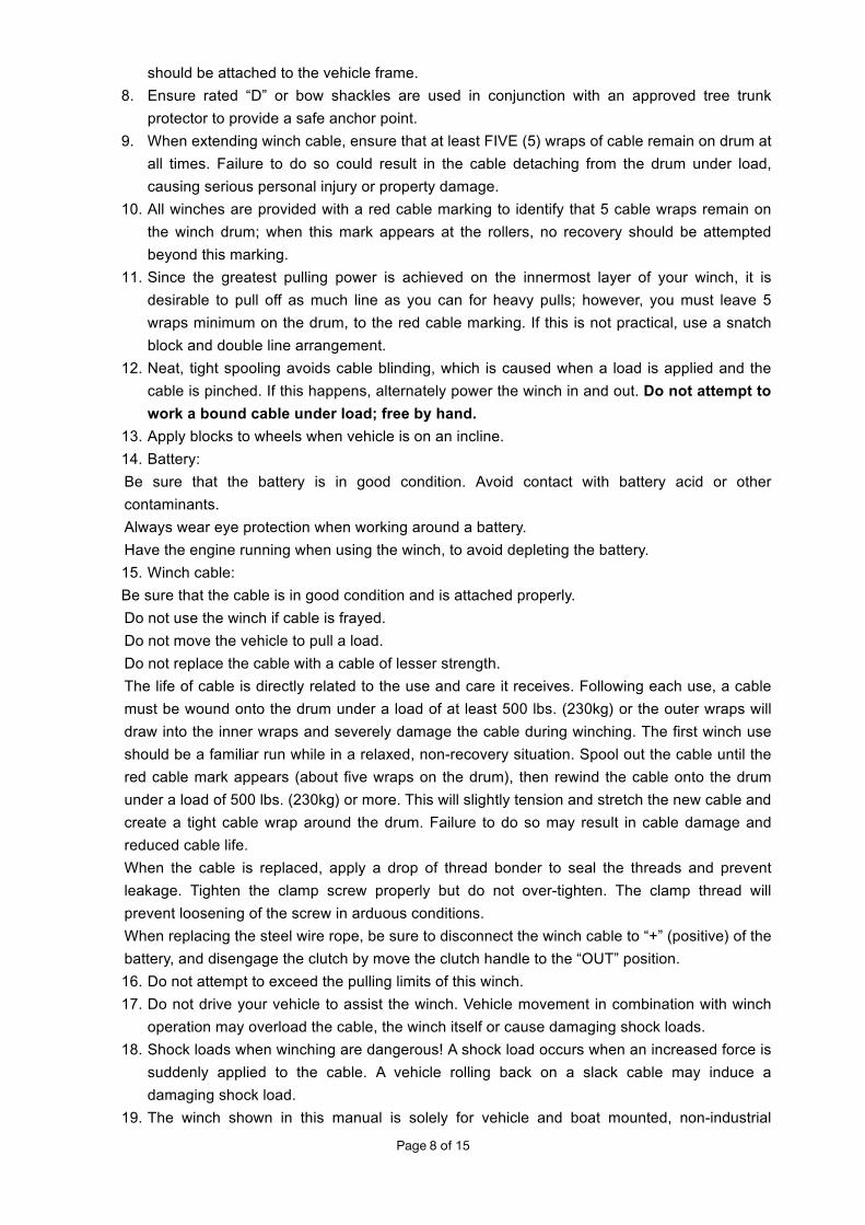
4. This electric winch includes an external wireless remote control.
(A) Radio control: Insert plug into the vehicle’s 12V power port. Use the handheld controller and
press button “IN” or “OUT” for wire rope in or out. The radio control system is exclusive to
each winch.
(B) Wire control:
Step 1 Connect one end of the control cable to the interface of the handheld controller;
Step 2 Connect the other end to the interface of the plug, then put the plug into the socket,
press button “IN” or “OUT” for wire rope in or out.

Page of 15 10
Radio Control Specifications:
Working Voltage 9V–12V
Frequency 433MHz
Power 10mW
Working Temperature -4o to 140 oF
Maximum Control Distance 100 ft.
5. To commence winching operation, start vehicle engine, place transmission in neutral, maintain
engine speed at idle. Never winch with your vehicle in gear or in park, which can damage
your vehicle’s transmission.
6. Never wrap the cable around an object and hook onto the cable when winching.
7. Keep hands, clothing, hair and jewelry clear of the drum area and cable when winching.
8. Never use the winch if the cable is frayed, kinked or damaged.
9. Never allow anyone to stand near the cable, or in line with the cable behind the winch while it
is under power. If the cable should slip or break, it can suddenly whip back towards the winch,
causing a hazard for anyone in the area . Always stand well to the side while winding.
10. Remove switch from 12V power port when winch is not in use.
11. Do not operate multiple winches with same frequency at the same time by remote control
within a distance of 220 feet; interference will occur among radio signals with same frequency.
12. If water enters the handheld controller, immediately remove battery and clean the circuit board
with ethyl alcohol (density required ≥98%).
13. Replace batteries in the handheld controller regularly; low voltage will affect performance.

Page of 15 11
USE OF WIRELESS CONTROL
The control handle has a 2-in-1 function. It is a wireless control as well as a cable-operating control.
Before you use the control in the wireless mode, you must install the battery to make it operational.
With the battery installed, the control will work remotely. There is no need to remove the battery
when using the cable since the attached cable overrides the remote function.
MAINTENANCE
It is highly recommended that the winch be used at least once a month. Simply power the cable out
50 feet, free spool 16 feet and then power back in. This will keep all components in good working
condition so that the winch can be relied on when needed. Contact your authorized service center
for technical assistance and repairs.

Page of 15 12
DIAGRAM & PARTS LIST

Page of 15 13
Item Part No. Description Qty. Item Part No. Description Qty.
1# 7329200.3-20
Washer 2 25# 7329200.3-1 Gear Box Base 1
2# 7329200.3-13
SunGear-Input 1 26# 7329200.3-2 Gear Housing 1
3# 7329200.3.1 Gear Carrier Ass'y-Input 1 27# 7329200.3-3 Inner Gear I 1
4# 7329200.3.2 Gear Carrier Ass'y-Intermediate 1 28# 7337100.3-1
0 Inner Gear Ⅱ 1
5# 7329200.3-9A
Cushion 1.2MM Thickness 2 29# 7329200.3-1
4 Gasket 9500 3
6# 7329200.3.3 Gear Carrier Ass'y-Output 1 30# 7337101.3-1
1C Gear Box End Cover 1
7# 7329200.3.3-1A
Outer Spline 1 31# GB70-85 M4*25
Bolt M4X25 10
8# GB894-86 32 Retaining Ring 2 32# 7329100.3-12
Bearing 1
9# 7329200.2 Drum Ass'y 1 33# 7329200.0-9 Label Plate 1
10# GB79-85 M8*12 Bolt for Brake M8X12 1 34# 7329200.3-4 Shaft Sleeve 1
11# 7329200.4A Brake Ass'y 1 35# 7329200.3-8 Stainless Clutch Spring 1
12# 7329200.4-1 Coupling Joint 1 36# 7329200.3-5 Clutch Washer 1
13# 7329200.1.2A
Rotor,12V 1 37# 7329200.3-6 Stainless Clutch Handle Washer Cover
1
14# GB955-87 18 Waveform washer Ø18 2 38# 7341100.3-7 Ball Clutch Handle 1
15# 7329200.1-5 Long Bolt M6X156 2 39# GB65-85 M6*8 Bolt M6X8 1
16# 7309200.1-4B
Motor End Cover 1 40# 7341100.5 Wire Rope 9.2MMX28.5M 1
17# 7329200.1.3.1
Carbon Ass'Y 1 41# GB/T39 M10 Mounting Nut M10 4
18# 7317102.1.1 Stator 1 42# GB/T1228-91 M10*32
Mounting Bolt M10x32 4
19# GB70-85 M8*25
Link Screw M8X25 4 43# GB7244-87 10
Lock Washer Ø10 4
20# 7329200.1-1A
Motor base 1 44# 7329200.0-4 Hook (Size 3/8in.) 1
21# 7329200.0-3 Nylon bearing 2 45# 7317100.7A Hawse Fairlead 1
22# 7329200.0-2A
Tie Bar 2 46# GB/T1229-91 M12
Fairlead Fixing Nut M12 2
23# GB70-85 M4*16
Bolt M4X16 9 47# GB/T1228-91 M12*25
Fairlead Fixing Bolt M12X25 2
24# GB93-87 4 Lock Washer 4 19 50# 7329100.6 OR
Mini OEM Solenoid Box Ass'y 1

Page of 15 14

Page of 15 15
Item No. Part No. Description Qty
1 7329200.60.1-2 Control box cover 1
2 GB70.2 M5x12 M5x12 Screw 10
3 GB/T 41 M5 M5 Nut 2
4 GB70.2 M8X12 Receiver 1
5 GB/T 862.1 8 M8x12 bolt 4
6 732510-24 M8 washer 4 7 GB/T97.18 A2 8 flat washer (stainless) 4 8 GB70.2 M6X10 Long red cable with yellow sleeve 1
9 GB/T862.1 6 Short black cable 1
10 7329100.6.1-11 Washer-contactor 1
11 7329100.6.1-12 M8 nut 4
12 7329100.6.1-15 Short black cable with black sleeve 1
13 7329100.6.1-13 Short red cable 1
14 7337180.6-3 M5 Bolt 2
15 GB/T6174 M8 OEM box plate 1
16 GB/T 862.1 6 M6 washer 3 17 GB 70.2 M6x10 M6x10 bolt 3 18 732510A(12V) ISM (Integrated solenoid module) 1 19 7329103.1-4 Thin black cable 1
20 GB41/T M4 M4 nut 4
21 7337180.0-24 Cover 1
22 7337180.0-20 Plug 1
23 GB/T 819.2 M4X12 M4 Bolt 4
24 7329200.6A-6 Control box plate base 1
25 7329200.6A-7 Control box plate base washer 1
26 GB15855.1 Ø5X8 5x8 Rivet 2
27 329200.6A-35AA Control box mount bracket 1
28 7329200.6.1-28A Fixing bar 2 29 7329100.6.1-17 Long black cable 1 30 7337180.6.5 Control plug 1 31 7337180.6.6 Wire for control 1 32 7329200.6 Remote Control 1
WARRANTY One Year Limited Warranty
Distributed by
Northern Tool + Equipment Co.
Burnsville, MN 55337-0499
Made in China