Embed Size (px)
Citation preview

* Corresponding author: Nira Saadun, Department of Power System, TNB Research Sdn. Bhd, Bangi, Selangor Darul Ehsan, Malaysia. E-mail: [email protected] 1,2,3,4 Department of Power System, TNB Research Sdn. Bhd, Bangi, Selangor Darul Ehsan, Malaysia. 5 Department of Transmission, Tenaga Nasional Berhad, Bangunan Dua Sentral, Kuala Lumpur, Malaysia.
Copyright © JES 2017 on-line : journal/esrgroups.org/jes
Nira Saadun1,*,
Ir. Dr. Sheikh
Kamar Sheikh
Abdullah2,
Mohd Khairun
Nizam Mohd
Sarmin3,
Muhamad
Tarmizi Azmi4,
Nik Sofizan Nik
Yusuf5
J. Electrical Systems 13-3 (2017): 444-456
Regular paper
Modelling and Implementation of
Intelligent Electronic Devices (IED) in
Real-Time Hardware-in-the-Loop (HIL)
Test System
JES
Journal of Journal of Journal of Journal of Electrical Electrical Electrical Electrical SystemsSystemsSystemsSystems
Modern power grid utilizes a sophisticated network of Intelligent Electronic Devices (IEDs). Proper coordination of IEDs is required to ensure safe, reliable and efficient of grid operations. This paper presents Real-Time Hardware-in-the-Loop (HIL) simulation test system modelled with RT-LAB real-time simulator for the design and testing of TNB Wide Area Defence Plan (WADP) scheme. The modelling of IEDs, which is one of the crucial components in this HIL test system, equipped with protection, control logics, metering and communication functions is developed. An overcurrent protection relay based on Inverse-Definite Minimum Time (IDMT) is modelled as key protection element function. Therefore, the capability of the modelled IEDs in this HIL test system is demonstrated towards the design and testing of TNB WADP scheme.
Keywords: Intelligent Electronic Device; Real-Time Simulation; Wide Area Defence Plan; Hardware-
in-the-Loop; Inverse-Definite Minimum Time.
Article history: Received 19 March 2016, Accepted 17 June 2017
1. Introduction
The Hardware-in-the-Loop (HIL) testing is increasingly recognized as an effective
approach in validating the power system model and design scheme. As traditional software-
based simulation has the disadvantage of being unable to exactly replicate real operational
condition, this HIL testing capable to increase the realism of the simulation and provides
access to hardware features which are currently not available in software-only simulation
model. Hence, this may reduce the risks of discovering an error in the very last stage of the
on-the-field testing [1,8].
An Intelligent Electronic Device (IED) is a microprocessor-based controller of power
system equipment. IED senses voltage and current, and capable of issuing control
commands, such as tripping of circuit breaker. The extended functionality of an IED can be
separated into the following groups such as protection, control, monitoring, metering and
communication. In this paper, the HIL test system for TNB Wide Area Defence Plan
(WADP) scheme developed by TNB Research Power System Group (TNBR-PSG)
incorporates virtual IED model. The “virtual IED” term is referred to IED that modelled
virtually in HIL test system instead of using physical IED. This is to minimize the number
of physical IED in used since the TNB WADP scheme requires more than 80 IEDs for
monitoring and control purposes. Therefore, it is practically impossible to connect those
IEDs with the real-time simulator at a time.

J. Electrical Systems 13-3 (2017): 444-456
445
As wide range and interconnected power system network nowadays, protection relay
such as Inverse-Definite Minimum Time (IDMT) overcurrent relays is crucial in the power
system protection with its unique features that can be graded over a wide range of currents
and operating times. This function is modelled in the virtual IED in order to replicates
actual behaviour of protection element in the real TNB power grid when testing the TNB
WADP scheme.
2. Notation
The notation used throughout the paper is stated below.
Constants:
TMS
PMS
Overcurrent relay time multiplier setting
Relay pickup setting
I Measured load currents [Amps]
Ir Plug setting multiplier
3. Material and Method
Generally, the HIL test system involves three-main software which is RT-LAB,
ePHASORsim and MATLAB/Simulink. The following describes the software:
i. RT-LAB is real-time simulation software that offers model-based design interacts
with real-world environments.
ii. ePHASORsim is a phasor-domain type power system dynamic simulation tool. It
performs simulation at a typical time-step in range of milliseconds i.e. 10 ms time-
step in this HIL test system, and provides phasor voltage and current information that
enables simulation of large-scale of power grid within a real-time.
iii. MATLAB/Simulink is a graphical programming environment for multi-domain
simulation and model-based design. Integrated with RT-LAB enables
MATLAB/Simulink model to interact with the real-world environment.
Fig. 1 Deployment diagram of HIL test system
Nira Saadun: Modelling of Intelligent Electronic Devices (IED) in Real-Time ...
446
As shown in Fig. 1 the HIL test system consists of real-time simulator and hardware
under test. The real-time simulator includes its software i.e. RT-LAB, ePHASORsim and
MATLAB/Simulink, and hardware i.e. real-time target, analog/digital input/output (I/O)
modules etc. The hardware under test includes embedded system on Real-Time Application
Platform (RTAP), Intelligent Electronic Devices (IED) and servers for data historian i.e. PI
Historian, and IEC 61850 MMS server.
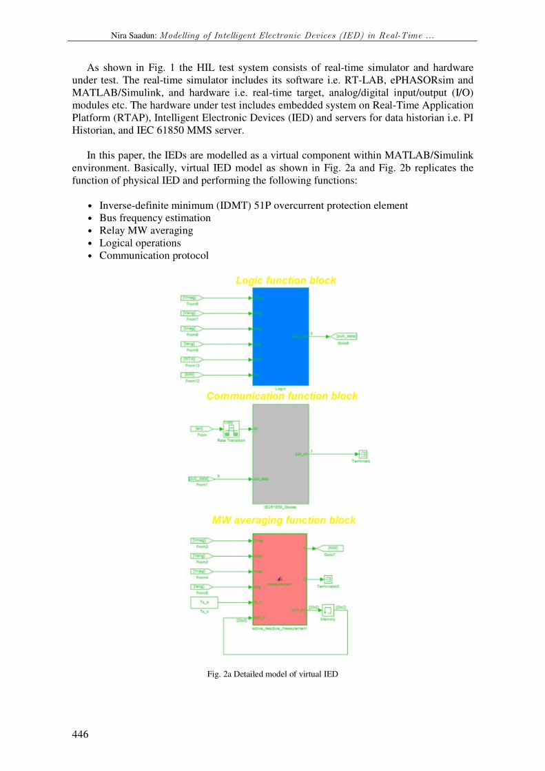
In this paper, the IEDs are modelled as a virtual component within MATLAB/Simulink
environment. Basically, virtual IED model as shown in Fig. 2a and Fig. 2b replicates the
function of physical IED and performing the following functions:
• Inverse-definite minimum (IDMT) 51P overcurrent protection element
• Bus frequency estimation
• Relay MW averaging
• Logical operations
• Communication protocol
Fig. 2a Detailed model of virtual IED

J. Electrical Systems 13-3 (2017): 444-456
447
Fig. 2b Detailed model of IDMT
3.1 Inverse-Definite Minimum (IDMT) 51P Overcurrent Protection Element
The characteristics of an IDMT overcurrent relay is depending on the type of standard
selected for the relay operation. The selected standard, IEC 60255 defines a number of
standard characteristics as follows:
• Standard Inverse (SI)
• Very Inverse (VI)
• Extremely Inverse (EI)
• Long Inverse (LI)
Equations for relay a characteristic to IEC 60255 is define as follows:
1)^( −
×=
PI
ATMSt
r
(1)
(2)
where TMS is overcurrent relay time multiplier setting with range 0.01 to 10, I is measured
load currents, Ir is plug setting multiplier, PMS is relay pickup setting, A and P is the
coefficient based on relay characteristics.
TABLE I
DIFFERENT TYPES OF INVERSE CHARACTERISTICS CURVES
Relay Characteristic Coefficient
A P
Standard Inverse (SI) 0.14 0.02
Very Inverse (VI) 13.5 1
Extremely Inverse (EI) 80 2
Long Inverse (LI) 120 1
Any of the standards can be used to implement a characteristic curve for an overcurrent
relay. An overcurrent relay has a minimum operating current, known as the current setting

Nira Saadun: Modelling of Intelligent Electronic Devices (IED) in Real-Time ...
448
of the relay. The current setting must be chosen so that the relay does not operate for the
maximum load current in the circuit being protected, but does operate for a current equal or
greater to the minimum expected fault current. Although by using a current setting that is
only just above the maximum load current in the circuit a certain degree of protection
against overloads as well as faults may be provided, the main function of overcurrent
protection is to isolate primary system faults and not to provide overload protection. In
general, the current setting will be selected to be above the maximum short time rated
current of the circuit involved.
The IDMT 51P overcurrent protection element model in HIL test system for TNB
WADP scheme is developed based on general IDMT equation as (1) and require input
settings such as equipment apparent power rating, equipment voltage rating, current
transformer primary and secondary current, measured load current, overload ratio for relay
to start pickup, overcurrent relay actual plug setting, overcurrent relay time dial multiplier,
and curve type of IDMT characteristic. Thus, the IDMT equation model is programmed
with MATLAB code function block.
3.2 Bus Frequency Estimation Modelling
Since the frequency of the load buses cannot be obtained directly from the power system
solver, a bus frequency estimation method is used to estimate the load bus frequency. Bus
frequency is estimated from two samples of bus voltage phase angle thus the slip frequency
(per-unit deviation of frequency from its nominal) at a respective bus is calculated.
With ePHASORsim, only generator bus frequency can be obtained directly from the
solver based on the speed of the generator. Therefore, frequency obtained at generator bus
is used as a benchmark. Based on IEEE 39-bus test system, a simulation has been
performed to compare frequency obtained from the solver and the estimated one. The
comparison results of frequency at different generator buses are shown in Fig. 3 and Fig. 4.
From the figures, except during transient period i.e. within first 3 seconds after a
disturbance, it is shown that the estimated frequency matches the actual frequency
measured at the generator buses.
Fig. 3 Bus frequency at generator Bus 30
Fig. 4 Bus frequency at generator Bus 31

J. Electrical Systems 13-3 (2017): 444-456
449
3.3 Relay MW Averaging Modelling
In the physical IED that is used in WADP system, the real power (MW) is not computed
instantaneously however it is calculated within frame of 10 cycles. Thus, when the system
frequency is at nominal i.e. 50 Hz, therefore the calculation of MW is within 200 ms. Since
MW is an important measurement element in WADP system, hence the virtual IED have to
replicate this characteristic as standard so that the HIL test system behaves like an actual
system.
In HIL test system, MATLAB function block is used to perform MW calculation based
on moving average of 10 windows. Fig. 5 and Fig. 6 shows the MW characteristics
computed by virtual IED. From the figures, it is shown that the time taken for calculating
the MW during ramp-up and ramp-down periods were around 200 ms.
Fig. 5 IED15 MW during ramp-up period
Fig. 6 IED15 MW during ramp-down period
3.4 Logical Operations Modelling
In WADP system, logical operations are used in physical IED for detecting line
tripping, overloading etc. Depending on the function of the IED, logical function developed
might be differ from one to another. Similarly, the logical operations developed in physical
IED are replicated in virtual IED. The example of logical function modelled in virtual IED
is shown in Fig. 7.

Nira Saadun: Modelling of Intelligent Electronic Devices (IED) in Real-Time ...
450
Fig. 7 Example of virtual IED logic diagram modelling
3.5 Communication Protocol Modelling
Communication protocol plays important role in WADP system. In this HIL test system
communication protocol is used for exchanging data between IEDs e.g. between virtual
IED and RTAP. The most common communication protocol uses in the HIL test system is
IEC 61850 GOOSE and MMS. IEC 61850, the only international standard based on
internet communication platform for the common parts of the substation automation
systems (SAS), is widely practiced in recent years [2-6]. In [7] RTDS is utilized to simulate
the power system network and platform MMS client is realized by a specialized tool of
RTDS. As commercial external IEDs act as MMS server, by using this tool, all data
exchange between MMS server and client can directly be fed to the simulation environment
of RTDS. In this paper, only IEC 61850 GOOSE publisher and subscriber are being
modelled in virtual IED since the real-time simulator is not supporting IEC 61850 MMS.
Hence, the IEC 61850 MMS is treated differently i.e. with IEC 61850 MMS server
developed outside of the real-time simulator. This requires IEEE C37.118 slave
communication protocol for data exchange between the real-time simulator and the server.
In this HIL test system, multiple of IEC 61850 MMS servers are virtually created in a
physical hardware that acts as virtual IEDs. Fig. 8 shows an example of virtual IED
communication protocol block i.e. IEC 61850 GOOSE publisher. Both IEC 61850 GOOSE
and MMS communication protocols in virtual IED imports Configured IED Description
(CID) files from the physical IEDs.

J. Electrical Systems 13-3 (2017): 444-456
451
Fig. 8 Example of virtual IED communication protocol modelling
4. Result and Discussion
In order to validate the model, the virtual IEDs are tested with TNB power system in the
real-time simulation environment. Overcurrent protection is one of the common protection
functions available in TNB power grid. Since this protection element is believed to be
highly influencing the WADP designed scheme, an IDMT 51P overcurrent protection
element is modelled in the virtual IED to replicate protective function in order to simulate
the actual power system responses. The following are the lists of virtual IED that are
equipped with IDMT which has been tested in WADP scheme:
• XGT1 – IED25
• XGT2 – IED27
• XGT3 – IED29
• Tie-line L1 – MIED
• Tie-line L2 – MIED
The 51P overcurrent common settings were retrieved from the actual TNB CAPE
(Protection Operation Setting) software. The details of the settings are as the following:
1) Tie-lines
• Rated MVA: 250 MVA
• Rated voltage: 230 kV
• CT primary rating: 1200 A
• CT secondary rating: 1 A
• Plug setting: 1.1 A
• Time dial multiplier (TMS): 0.2
• IDMT curve type: IEC standard inverse (SI)
2) XGT transformers
• Rated MVA: 750 MVA
• Rated voltage: 500 kV
• CT primary rating: 1000 A
• CT secondary rating: 1 A

Nira Saadun: Modelling of Intelligent Electronic Devices (IED) in Real-Time ...
452
• Plug setting: 1.5 A
• Time dial multiplier (TMS): 0. 35
• IDMT curve type: IEC standard inverse (SI)
4.1 Validate Modelled IDMT with Actual Recorded Data
In order to validate the characteristic of the modelled IDMT, an actual recorded data
from BEN disturbance recorder based on 19th of July 2016 events was used as a benchmark.
The tie-line secondary RMS currents were computed based on the recorded three-phase
data. Then, the tie-line yellow-phase RMS current was selected as a reference.
Fig. 9 shows the tie-line secondary current versus IDMT characteristics. Whereas Fig.
10 shows the IEC standard inverse (SI) curve starting from IDMT pickup until the tie-line
tripped. It is shown that both IDMTs were pickup at the similar time and current i.e. 1.1 A
secondary. Unlike the actual IDMT, the modelled IDMT was pickup several times at the
beginning of the rising of current perhaps due to the fluctuation of current and there is no
data filtering is modelled in the virtual IED. The tie-line was tripped at time 2.664 s, 2.5862
s after the IDMT was pickup. It is observed that the modelled IDMT operating time was
slightly delayed, which was 4.215 s after IDMT was pickup. Therefore, if the secondary
line current is maintained at 1.532 A i.e. the last operating current measured just before line
was tripped, the modelled IDMT operating time is delayed by 1.6288 s. From the
observation, the inconsistency of the operating time between these IDMTs perhaps due to:
• The actual relay may “seen” the secondary current differently since in this validation,
the secondary RMS current were computed based on the recorded three-phase data
from the disturbance recorder.
• Other actual relay settings/parameters such as breaker operation etc. were not being
considered in the modelled IDMT.
Fig. 9 Tie-line secondary current vs. IDMT characteristics

J. Electrical Systems 13-3 (2017): 444-456
453
Fig. 10 IEC standard inverse curve based on actual recorded tie-line primary current
4.2 Validate Modelled IDMT with Real-Time Simulation
The IDMT characteristic was further assessed. Through the real-time simulation, the
19th of July 2016 events have been re-produced to validate the IDMT characteristic for tie-
lines. The simulation sequence of events is as the following:
• @t = 0 s: Start simulation
• @t = 5 s: Trip TBIN_U4 and de-load JMJG_U2
• @t = 8 s: Apply runback of HVDC and hydro at local frequency 49.8 Hz
• @t = 10.3 s: Trip JMJG_U2
• @t = 20 s: Stop simulation
Fig. 11 shows the simulated tie-line secondary current versus IDMT characteristics.
Whereas, Fig. 12 shows the IEC SI curve starting from IDMT pickup until tie-line tripped.
It is observed that the IDMT was pickup at time 11.09 s with secondary current 1.102 A.
The tie-line was tripped at 15.2 s, which was 4.083 s after the IDMT was pickup. The
measured primary current before the tie-line tripped was 1858A.
Fig. 11 Simulated tie-line secondary current vs IDMT characteristics

Nira Saadun: Modelling of Intelligent Electronic Devices (IED) in Real-Time ...
454
Fig. 12 IEC standard inverse curve based on simulated tie-line primary current
The second test scenario was created with the real-time simulator to validate the IDMT
for XGT transformers. The simulation sequence of events is as the following:
• @t = 0 s: Start simulation
• @t = 5 s: Trip ATWR-BTRK 500 kV BL04 line
• @t = 10 s: Trip ATWR XGT1 and XGT2
• @t = 20 s: Stop simulation
Fig. 13 shows the simulated XGT3 secondary current versus IDMT characteristics.
Whereas, Fig. 14 shows the IEC SI curve starting from IDMT pickup until transformer
tripped. It is observed that the IDMT was pickup at time 10.13 s with secondary current
2.375 A. The XGT3 was tripped at 13.32 s, which was 3.183 s after the IDMT was pickup.
The measured primary current before the XGT3 tripped was 3220 A.
Fig. 13 Simulated XGT3 secondary current vs. IDMT characteristics

J. Electrical Systems 13-3 (2017): 444-456
455
Fig. 14 IEC standard inverse curve based on simulated XGT3 primary current
5. Conclusion
This paper presents a comprehensive Intelligent Electronic Devices (IED) modelling in
Hardware-in-the-Loop (HIL) simulation test system developed by TNB Research Power
System Group (TNBR-PSG) for TNB Wide Area Defence Plan (WADP) scheme. The IEDs
were virtually modelled in the HIL test system within MATLAB/Simulink environment.
Thus, the model-based designs of HIL test system were successfully demonstrated in order
to replicate actual behaviour of TNB power system towards the design and testing of
WADP scheme. The communication protocols of the virtual IEDs were modelled and the
IEC 61850 MMS servers were developed outside of the real-time simulator environment
hence communications between IEDs are established. In summary, the contribution of this
paper can be listed as follows:
• Real-time modelling and simulation for TNB WADP scheme.
• Demonstration of virtual IEDs including IDMT 51P overcurrent protection element
modelling in real-time simulation.
Acknowledgment
The authors gratefully acknowledge the contribution of TNBR project members and
TNB Transmission for their supports during the development works.
References [1] B. Lu, A. Monti, and R. Dougal, “Real-time hardware-in-the-loop testing during design of power
electronics controls,” in Proc. IEEE IECON, Nov. 2003, vol. 2, pp. 1840–1845.
[2] IEC 61850-5: Communication networks and systems in substations – Part 5: Communication requirements
for functions and device models State Grid Corporation of China, Q/GDW383 technical guides of
intelligent substation[S]. 2003.
[3] IEC 61850-9-1: Communication networks and systems in substations – Part 9-1: Specific communication service mapping (SCSM) – Sampled values over serial unidirectional multi-drop point to point link[S].
2003.
[4] IEC 61850-9-2: Communication networks and systems in substations – Part 9-2: Specific Communication
service mapping (SCSM) – Sampled values over ISO/IEC 8802-3[S]. 2003.

Nira Saadun: Modelling of Intelligent Electronic Devices (IED) in Real-Time ...
456
[5] Lars Andersson, Klaus-Peter Brand, Christoph Brunner and Wolfgang Wimmer. Reliability investigations
for SA communication architectures based on IEC 61850[C]. Proceedings of IEEE Power Tech 2005: 604-
612.
[6] Skeie T, Johannessen S, Brunner C. Ethernet in substation automation [J]. IEEE Control System Magazine,
2002, 22(3):43-51
[7] Pouya Jamborsalamati, Abhinav Sadu, Ferdinanda Ponci and Antonello Monti for A Flexible HIL Testing Platform for Performance Evaluation of IEC 61850-based Protection Schemes. IEEE Power and Energy
Society General Meeting, 1944-9933. 2016
[8] Lin Feng, Qing Zhong, Nanhua Yu, Kun Wang, Guojie Li, and Kan Chen for Hardwareintheloop
Simulation Platform of Photovoltaic Grid Connected System. TELKOMNIKA Indonesian Journal of
Electrical Engineering Volume 12, No. 4, Pages 2465-2473. 2014


![for model : TM-9200s-U240n-5A TM-9300s-U240n-5A DELAB ... 2013.pdf · (refer to IDMT Graph) Select the desired IDMT curve using the [ Up / (+) ] or [ Down / (-) ] button. Newly selected](https://img.pdfslide.net/doc/110x75/60dab49f5dabad678957ab66/for-model-tm-9200s-u240n-5a-tm-9300s-u240n-5a-delab-2013pdf-refer-to-idmt.jpg)