Embed Size (px)
Citation preview
13 Deflections of beams
13.1 Introduction
In Chapter 7 we showed that the loading actions at any section of a simply-supported beam or cantilever can be resolved into a bending moment and a shearing force. Subsequently, inChapters 9 and 10, we discussed ways of estimating the stresses due to these bending moments and shearing forces. There is, however, another aspect of the problem of bending which remains to be treated, namely, the calculation of the stifiess of a beam. In most practical cases, it is necessary that a beam should be not only strong enough for its purpose, but also that it should have the requisite stiffness, that is, it should not deflect from its original position by more than a certain amount. Again, there are certain types ofbeams, such as those camed by more than two supports and beams with their ends held in such a way that they must keep their original directions, for which we cannot calculate bending moments and shearing forces without studying the deformations of the axis of the beam; these problems are statically indeterminate, in fact.
In this chapter we consider methods of finding the deflected form of a beam under a given system of external loads and having known conditions of support.
13.2 Elastic bending of straight beams
It was shown in Section 9.2 that a straight beam of uniform cross-section, when subjected to end couples A4 applied about a principal axis, bends into a circular arc of radius R, given by
1 M R EI - - - - (13.1)
where EI, which is the product of Young's modulus E and the second moment of area I about the relevant principal axis, is the flexural stiffness of the beam; equation ( 13.1) holds only for elastic bending.
Where a beam is subjected to shearing forces, as well as bending moments, the axis of the beam is no longer bent to a circular arc. To deal with this type of problem, we assume that equation (13.1) still defines the radius of curvature at any point of the beam where the bending moment is M. This implies that where the bending moment varies from one section of the beam to another, the radius of curvature also vanes from section to section, in accordance with equation (13.1).
In the unstrained condition of the beam, Cz is the longitudinal centroidal axis, Figure 13.1, and Cx, Cy are the principal axes in the cross-section. The co-ordinate axes Cx, Cy are so arranged that the y-axis is vertically downwards. This is convenient as most practical loading conditions give rise to vertically downwards deflections. Suppose bending moments are applied about axes parallel to Cx, so that bending is restricted to the yz-plane, because Cx and Cy are principal axes.
296 Deflections of beams
Figure 13.1 Longitudinal and principal Figure 13.2 Displacements of the longitudinal centroidal axes for a straight beam. axis of the beam.
Consider a short length of the unstrained beam, corresponding with D F on the axis Cz, Figure 13.2. In the strained condition D and F are dsplaced to D' and F', respectively, which lies in the yz- plane. Any point such as D on the axis Cz is displaced by an amount v parallel to Cy; it is also hsplaced a small, but negligible, amount parallel to Cz.
The radius of curvature R at any section of the beam is then given by
d2v - 1 - dz2
(13.2) - - R
* [1 + ( $)2r We are concerned generally with only small deflections, in which v is small; thls implies that (dv/dz) is small, and that ( d ~ / d z ) ~ is negligible compared with unity. Then, with sufficient accuracy, we may write
d 2 v 1 R dz2
(13.3) - = f-
The equations (13.1) and (1 3.3) give
d ' v dz2
(13.4) & E I - = A4
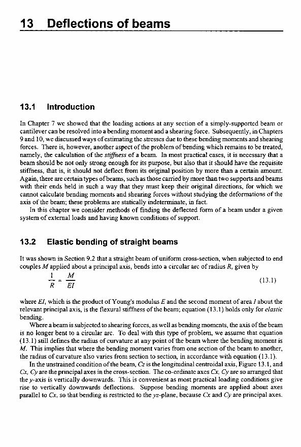
We must now consider whether the positive or negative sign is relevant in this equation; we have already adopted the convention in Section 7.4 that sagging bending moments are positive. When a length of the beam is subjected to sagging bending moments, as in Figure 13.3, the value of (dv/dz) along the length diminishes as z increases; hence a sagging moment implies that the curvature is negative. Then
(13.5) d 2 v dz'
E I - = - M
where M is the sagging bending moment.
Elastic bending of straight beams 297
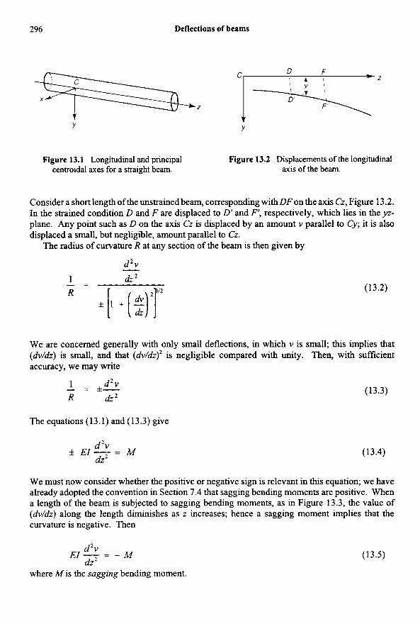
Figure 13.3 Curvature induced by sagging Figure 13.4 Deflected form of a beam in bending moment. pure bending.
Where the beam is loaded on its axis of shear centres, so that no twisting occurs, M may be written in terms of shearing force F and intensity w of vertical loading at any section. From equation (7.9) we have
- - - - d 2 M - dF - -w dz2 a2
On substituting for M from equation (1 3.5), we have
(13.6) - [ - E l $ ] d2 = 5 = -w dz2
Thls relation is true if EI vanes from one section of a beam to another. Where El is constant along the length of a beam,
d4v - dF dz4 dz
(13.7) - E l - - - = -w
As an example of the use of equation (13.4), consider the case of a uniform beam carrying couples M at its ends, Figure 13.4. The bending moment at any section is M, so the beam is under a constant bendmg moment. Equation (13.5) gives
d2v -
dz2 E I - - -M
On integrating once, we have
dv EI - dz = -Mz + A (13.8)
298 Deflections of beams
where A is a constant. On integrating once more
(13.9) 1 2
EIv = -- Mz’ + AI + B
where B is another constant. If we measure v relative to a line CD joining the ends of the beam, vis zero at each end. Then v = 0, for z = 0 and z = L.
On substituting these two conditions into equation (13.9), we have
1 2
B = 0 and A = -ML
The equation (13.9) may be written
(13.10) 1 EIv = -Mz(L - Z) 2
At the mid-length, z = U., and
(13.11) ML 2 v = - 8EI
which is the greatest deflection. At the ends z = 0 and z = L/2,
(13.12) d v - ML dv ML (iz 2 EI a!? 2 EI - at C; - = -- at D - -
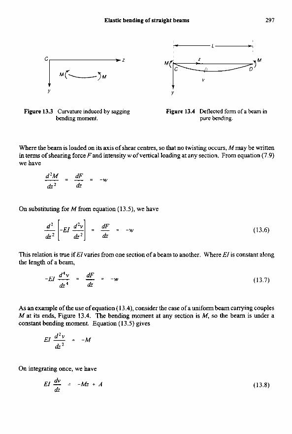
It is important to appreciate that equation (13.3), expressing the radius of curvature R in terms of v, is only true if the displacement v is small.
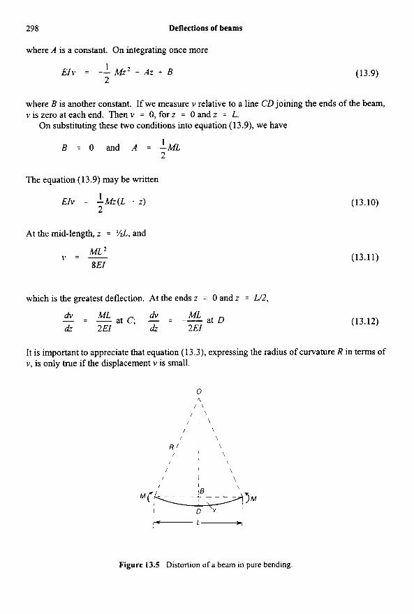
Figure 13.5 Distortion of a beam in pure bending.
Elastic bending of straight beams 299
We can study more accurately the pure bending of a beam by considering it to be deformed into the arc of a circle, Figure 13.5; as the bending moment M is constant at all sections of the beam, the radius of curvature R is the same for all sections. If L is the length between the ends, Figure 13.5, and D is the mid-point,
OB = 4-j
Thus the central deflection v, is
v = BD = R - \IR2 - ( L 2 / 4 )
Then
v = i i
Suppose W R is considerably less than unity; then
which can be written
1 v = - 1 I + - + . . . L 2 L 2 8R 4 R
But
and so
v = ML - i l + - M ~ L ~ + . . . I 8EI 4(E42
(13.13)
Clearly, if (L2/4Rz) is negligible compared with unity we have, approximately,
which agrees with equation (1 3.1 1). The more accurate equation (13.13) shows that, when (Lz/4R2)
300 Deflections of beams
is not negligible, the relationshp between v and A4 is non-linear; for all practical purposes this refinement is unimportant, and we find simple linear relationships of the type of equation (1 3.1 1) are sufficiently accurate for engineering purposes.
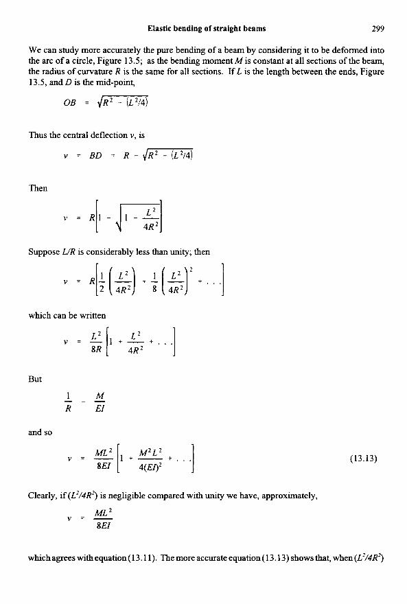
13.3 Simply-supported beam carrying a uniformly distributed load
A beam of uniform flexural stiffness EI and span L is simply-supported at its ends, Figure 13.6; it carries a uniformly distributed lateral load of w per unit length, whch induces bending in the yz plane only. Then the reactions at the ends are each equal to %wL; if z is measured from the end C, the bending moment at a distance z from C is
1 1 2
2 2 M = -WLZ - -WZ
Figure 13.6 Simply-supported beam carrying a uniformly supported load.
Then from equation ( 13 S),
d2v 1 1 dz2 2 2
E l - = -M = -- WLZ + - wz2
On integrating,
+ A dv WLZ 2 wz 3 EI- = - - + - dz 4 6
and
+ A z + B (1 3.14) wLz3 wz4
12 24 EIv = -- + -
Suppose v = 0 at the ends z = 0 and z = L; then
B = 0, and A = wL’I24
Cantilever with a concentrated load 301
Then equation (13.14) becomes
(13.15) wz EZv = - [L’ - 2Lz2 + z’] 24
The deflection at the mid-length, z = Y . , is
(1 3.16) 5wL4 v = - 3 84 El
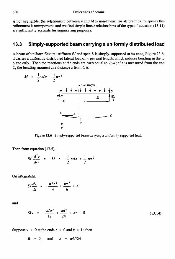
13.4 Cantilever with a concentrated load
A uniform cantilever of flexural stiffness Eland length L carries a vertical concentrated load Wat the free end, Figure 13.7. The bending moment a distance z from the built-in end is
M = -W(L - z )
Figure 13.7 Cantilever carrying a vertical load at the remote end.
Hence equation ( 13.5) gives
d2v dz2
EZ- = W(L - Z)
Then
E I k = w ( L z - i Z 2 ) -L A (13.17) dz
and
302 Deflections of beams
EIv = W( ;Lz2 - iz3) + Az + B
At the end z = 0, there is zero slope in the deflected form, so that dv/dz = 0; then equation (13.17) gives A = 0. Furthermore, at z = 0 there is also no deflection, so that B = 0. Then
wz 2 EIv = - (3L - Z) 6
Atthe free end,^ = L,
WL 3 VI. = -
3 EI (13.18)
The slope of the beam at the free end is
0, = (2) ? = L 2EI (13.19)
- WL2 - -
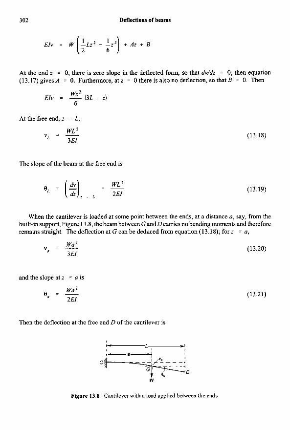
When the cantilever is loaded at some point between the ends, at a distance a, say, from the built-in support, Figure 13.8, the beam between G and D carries no bending moments and therefore remains straight. The deflection at G can be deduced from equation (13.18); for z = a,
(13.20) w a 3 v, = - 3 E/
and the slope at z = a is
(13.21) Wa 2
2EI eo = -
Then the deflection at the free end D of the cantilever is
Figure 13.8 Cantilever with a load applied between the ends.
Cantilever with a uniformly distributed load 303
W a ’ 3EI 2EI
V L = - wu3 + ( L - a) -
- - wu2 ( 3 ~ - a)
(13.22) -
6EI
13.5 Cantilever with a uniformly distributed load
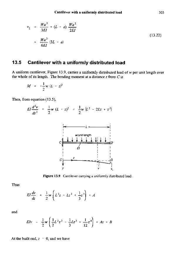
A uniform cantilever, Figure 13.9, carries a uniformly distributed load of w per unit length over the whole of its length. The bending moment at a distance z from C is
1 2
M = --w ( L - z)’
Then, from equation (13.5),
d‘v 1 1 dz’ 2 2
EI- = -W ( L - z)’ = -W (L2 - ~ L z + z’)
Figure 13.9 Cantilever carrying a uniformly distributed load.
Thus
EI- = -w L’z - Lz2 + -z3 + A * dz 2 7 3 7 and
2 2 1 I’ 3 12 ’ 1 1 EIv = -w -L’z’ - -Lz3 + -z4 + Az + B
At the built end, z = 0, and we have
304 Deflections of beams
- - & - O and v = O CL
ThusA = B = 0. Then
1 24
E ~ v = -W (6L2z2 - 4Lz3 + z4)
At the free end, D, the vertical deflection is
(13.23) WL 4 VL = -
8EI
13.6 Propped cantilever with distributed load
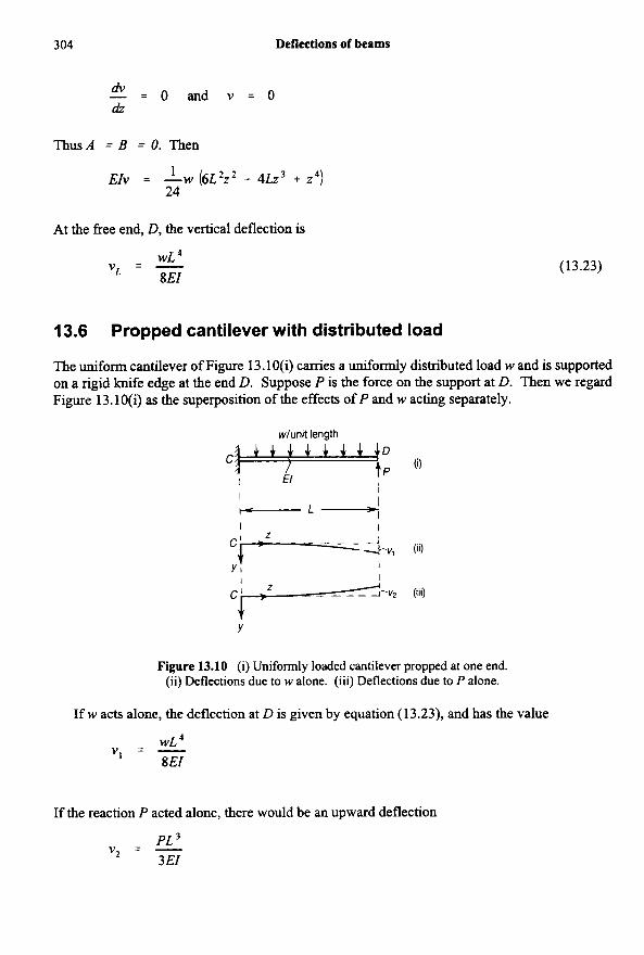
The uniform cantilever of Figure 13.1 O(i) carries a uniformly distributed load w and is supported on a rigid knife edge at the end D. Suppose P is the force on the support at D. Then we regard Figure 13.10(i) as the superposition of the effects of P and w acting separately.
Figure 13.10 (i) Uniformly loaded cantilever propped at one end. (ii) Deflections due to w alone. (iii) Deflections due to P alone.
If w acts alone, the deflection at D is given by equation (13.23), and has the value
WL 4 v , = - 8EI
If the reaction P acted alone, there would be an upward deflection
PL 3 v* = - 3 EI
Propped cantilever with distributed load 305
at D. If the support maintains zero deflection at D,
v , - v 2 = 0
Thls gives
P L 3 - WL - - - 3EI 8EI
or
3wL p = - 8
(13.24)
Problem 13.1 A steel rod 5 cm diameter protrudes 2 m horizontally from a wall. (i) Calculate the deflection due to a load of 1 kN hung on the end of the rod. The weight of the rod may be neglected. (ii) If a vertical steel wire 3 m long, 0.25 cm diameter, supports the end of the cantilever, being taut but unstressed before the load is applied, calculate the end deflection on application of the load. TakeE = 200GN/m2. (RNEC)
Solution
(1) The second moment of are of the cross-section is
I, = - (0.050)4 = 0.307 x m 4 T
64
The deflection at the end is then
(ii) Let T = tension in the wire; the area of cross-section of the wire is 4.90 x
elongation ofthe wire is then m2. The
e = - - - T(3) EA (200 x 109)(4.90 x
The load on the end of the cantilever is then (1000 - T), and this produces a deflection of
(1000 - fi(2)3 v = 3(200 x 109)(0.307 x
306 Deflections of beams
If this equals the stretching of the wire, then
(1000 - 71(2)3 - - T(3) 3(200 x 109)(0.307 x 1O-6) (200 x 109)(4.90 x 1O-6)
This gives T = 934 N, and the deflection of the cantilever becomes
v = (66)(2)3 = 0.00276 m 3(200 x 109)(0.307 x 1O-6)
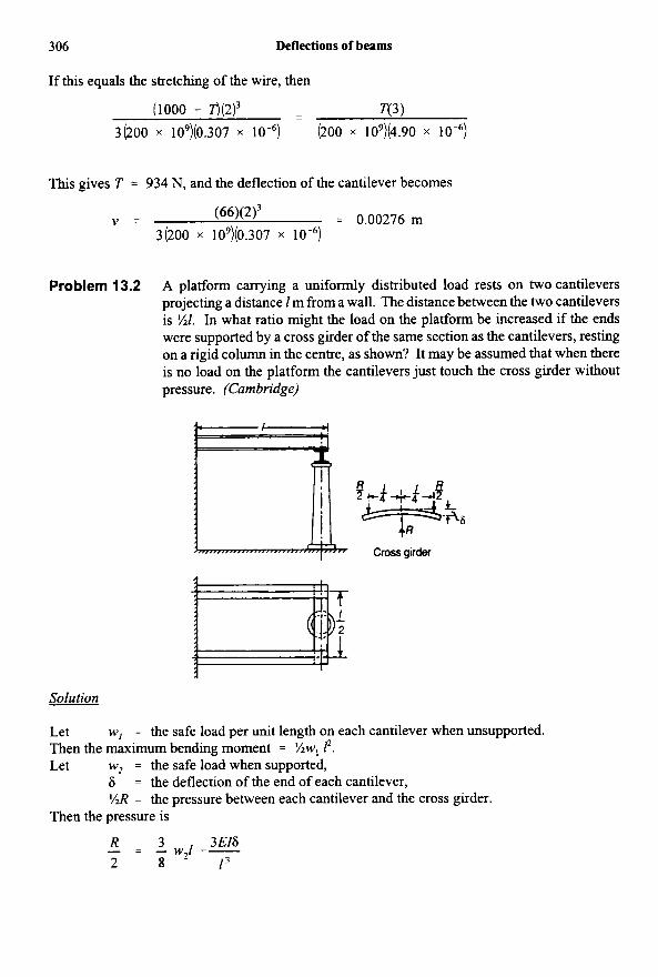
Problem 13.2 A platform carrying a uniformly distributed load rests on two cantilevers projecting a distance 1 m from a wall. The distance between the two cantilevers is %1. In what ratio might the load on the platform be increased if the ends were supported by a cross girder of the same section as the cantilevers, resting on a rigid column in the centre, as shown? It may be assumed that when there is no load on the platform the cantilevers just touch the cross girder without pressure. (Cambridge)
Solution
Let Then the maximum bending moment = %w, 12. Let w, = the safe load when supported,
w, = the safe load per unit length on each cantilever when unsupported.
6 = the deflection of the end of each cantilever, I/tR = the pressure between each cantilever and the cross girder.
Then the pressure is
3 3 E16 - - R - - w,l -- 2 8 - I’
Simply-supported beam carrying a concentrated lateral load 307
We see from the figure above that
(R/2)(1/4)3 - R13 i s = - -
3 EI 3 84 EI
I having the same value for the cantilevers and cross girder. Substituting this value of 6
R - 3w21 R - - - - -
2 8 128
or
48 65
R = -w21
The upward pressure on the end of each cantilever is YJ? = 24wJ/65, giving a bending moment at the wall equal to 24wJ2/65. The bending moment of opposite sign due to the distributed load is %wJ2. Hence it is clear that the maximum bending moment due to both acting together must occur at the wall and is equal to (% - 24/65) wJ2 = (17/130) wJ2. If h s is to be equal to % wIZ2, we must have w, = (65/17) w,; in other words, the load on the platform can be increased in the ratio 65/17, or nearly 4/1. The bending moment at the centre of the cross girder is 6~~1’165, which is less than that at the wall.
13.7 Simply-supported beam carrying a concentrated lateral load
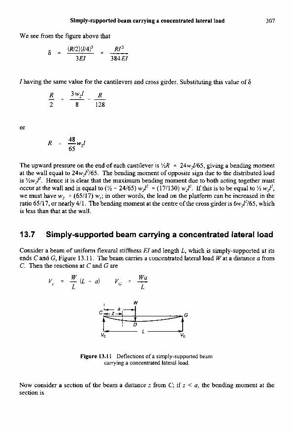
Consider a beam of uniform flexural stiffness EI and length L, which is simply-supported at its ends C and G, Figure 13.1 1. The beam carries a concentrated lateral load W at a distance a from C. Then the reactions at C and G are
Wa v, = E (L - u) vc = - L L
Figure 13.1 1 Deflections of a simply-supported beam carrying a concentrated lateral load.
Now consider a section of the beam a distance z from C; if z < a, the bending moment at the section is
308
M = v c z
Deflections of beams
and ifz > a,
M = V , Z - Mz - a)
Then
d2v dz2
EI- = -V, z for z < a
and
E& = -vC z + ~ ( z - a) for z > a dz2
On integrating these equations, we have
1 dv dz 2 (13.25) EI- = --Vc z 2 + A for z < a
dv 1
dz 2 E I - = --Vcz2 + W ( i z 2 -az) +A' for z > a
and
1 6
EIv = --Vc z 3 + AZ + B for z < a
(13.26)
(13.27)
+A'z + B' for z>a (13.28)
In these equations A, B, A ' and B' are arbitrary constants. Now for z = a the values of v given by equations (13.27) and(13.28) are equal, and the slopes given by equations (13.25) and(13.26) are also equal, as there is continuity of the deflected form of the beam through the point D. Then
1 1 6
--vc a 3 + A a + B = - -Vc 6 a 3 + W($-13 - t . 3 ) + A i a + B i
and
Simply-supported beam carrying a concentrated lateral load 309
These two equations give
(13.29)
Ai the extreme ends of the beam v = 0, so that when z = 0 equation (1 3.27) gives B = 0, and when z =L, equation (13.28) gives
We have finally,
1 W A = -V, L 2 -- (L - a)’ 6 6L
B = O
But Vc = W(L - a)/L, so that equations (13.30) become
Wa 6L
A = - (L - a)(2L - a)
B = O
(13.30)
(13.31)
310 Deflections of beams
Then equations (13.27) and (13.28) may be written
1 W 6 L 6 L
E I V = ~ L ’ - ~ u L + u ~ z f o r z < a
W W 6 L 6
EIv = - -(L - a)z3 t - (z’ - 3 m 2 )
The second relation, for z > a, may be written
3 (2L2 - 3aL+ u2 W E I v = - - ( L - a ) z 3 + -
6 L 6 L
(13.32)
(13.33)
(13.34)
Then equations (13.32) and (13.33) differ only by the last term of equation (13.34); ifthe last term of equation (13.34) is discarded when z < a, then equation (13.34) may be used to define the deflected form in all parts of the beam.
On putting z = a, the deflection at the loaded point D is
wa2 ( L - .)2 V D =
3 EIL
When W is at the centre of the beam, a = %L, and
WL V D = -
48EI
(13.35)
(13.36)
This is the maximum deflection of the beam only when a = %L.
13.8 Macaulay’s method
The observation that equations (13.32) and (13.33) differ only by the last term of equation (13.34) leads to Macaulay‘s method, which ignores terms which are negative withm the Macaulay brackets. That is, if the term [z -a ] in equation (13.34) is negative, it is ignored, so that equation (13.34) can be used for the whole beam. The method will be demonstrated by applying it to a few examples.
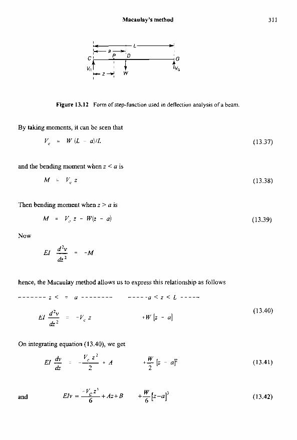
Consider the beam shown in Figure 13.12, which is simply-supported at its ends and loaded with a concentrated load W.
Macaulay’s method 31 1
Figure 13.12 Form of step-function used in deflection analysis of a beam.
By taking moments, it can be seen that
v, = w ( L - a ) / L (13.37)
and the bending moment when z < a is
M = vcz (13.38)
Then bending moment when z > a is
M = vc z - W(Z - a) (13.39)
Now
d2v dz2
El - = -M
hence, the Macaulay method allows us to express this relationship as follows
a < z < L - - - - - - - z < = a - _ - - _ _ - * - - -__ - - - - -
(13.40) +w [z - a] d’v
dz’ EI - = -Vc z
On integrating equation (13.40), we get
(13.41) v, z 2 W + A +- [z - a]’ dv dz 2 2
E / - 1 --
(13.42) -v z3 W
EIV = C + A ~ + B ++-.I’ 6 6 and
312 Deflection of barns
The term on the right of equations ( 13.40) and ( 13.4 1) must be integrated by the manner shown, so that the arbitrary constants A and B apply when z < a and also when z > a. The square brackets [ ] are called Macaulay brackets and do not appi'y when the term inside them is negative.
The two boundary conditions are:
a t z = 0, v = 0 and a t z = L , v = 0
Applying the first boundary condition to equation (13.42), we get
B = O
Applying the second boundary condition to equation (13.42), we get
0 = -V, L 3 / 6 + AL + W (L - ~ ) ~ / 6
or AL = W (L - a) L3/ (6L) - W (L - ~ ) ~ / 6
or A = W (L - a) L/6 - W (L - u ) ~ / ( ~ L )
- - W (L - a) {L - (L - a)Z/L} 6
:. EIv = -W(L - a)z3 / (6L)
+ w(L - a) (4 - (L - u ) ~ / L } x / ~
+ W[Z - aF/6
On putting z = a, we get the deflection at D, namely v,
i e. V D = (L - a) { - a 3 / L + (L - (L - a)2/L) a + 0) 6EI
= wL - a) { -a3/L + (L - ( L 2 - 2aL + a2)/L) a} 6EI
= N L - a) ( -a3/L + La - La + 2a2 - a3/L) 6EI
HqL - a)? a 2 or V D = 3 EIL
Simply-supported beam with distributed load over a portion of the span 313
If W is placed centrally, so that a = W2,
w( L - L / 2)2 ( L / 2 ) V D =
3 EIL
(13.43)
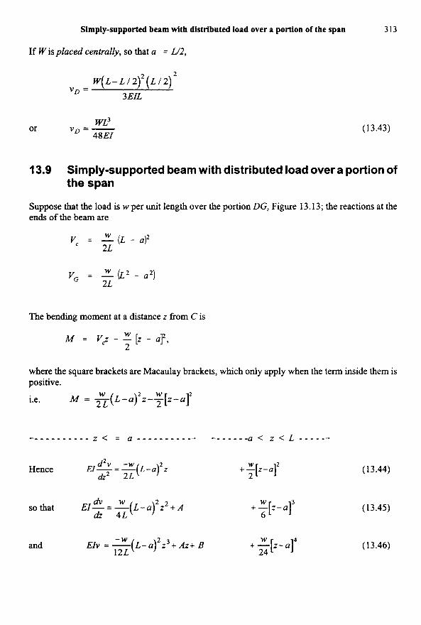
13.9 Simply-supported beam with distributed load over a portion of the span
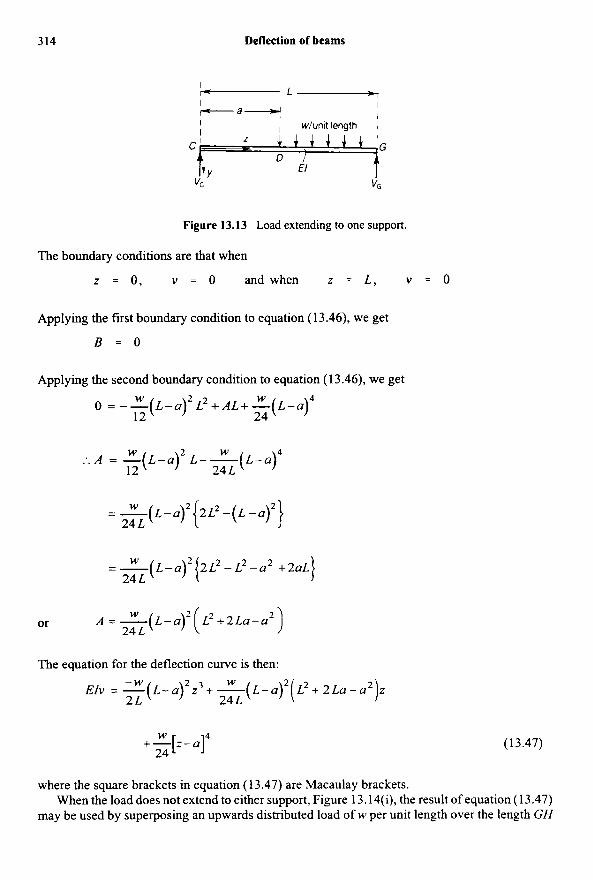
Suppose that the load is w per unit length over the portion DG, Figure 13.13; the reactions at the ends of the beam are
W vC = - (L - a)2 2L
W vc = - (p - a 2 ) 2L
The bending moment at a &stance z from C is
where the square brackets are Macaulay brackets, which only apply when the term inside them is positive.
M = - ( L - a ) 2 z - ~ [ z - a ] 2 W
2L i.e.
U)‘ z Hence EI-=-(L- d’v -w &2 2 L
d v w so that EI-= - ( L - a ) ’ z 2 + A
& 4L
and -W
EIv = - ( L - a ) ’ z 3 t A z t B 12L
+ “[.-.IZ 2
+“[.-a]’ 6
W t -[z- .I4
24
(13.44)
(13.45)
(13.46)
314 Deflection of beams
Figure 13.13 Load extending to one support.
The boundary conditions are that when
z = 0 , v = 0 andwhen z = L , v = 0
Applying the first boundary condition to equation (13.46), we get
B = O
Applying the second boundary condition to equation ( 1 3.46), we get W 2 W 4 o = - - ( L - U ) L ~ + A L + - ( L - u ) 12 24
W 2 W 4 : . A = - ( L - U ) L - - ( L - U )
12 24 L
= - " ( L-a) 2 { 2 L 2 - ( k ? ) 2 }
1 = - (L-u)2 (2L2-L2-u* W +2uL
A = - (L-u)2 ( W L 2 + 2 L u - u 2 )
EIv = - ( L - a ) 2 z 3 + - ( L - a ) -W W 2 ( L 2 + 2 L u - a 2 ) z
24 L
24 L
24 L or
The equation for the deflection curve is then:
2 L 24 L
(13.47) +-[,-.I4 W
24
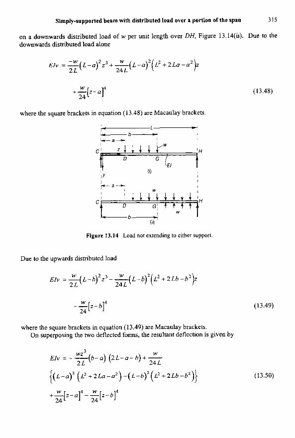
where the square brackets in equation (13.47) are Macaulay brackets. When the load does not extend to either support, Figure 13.14(i), the result of equation ( 1 3.47)
may be used by superposing an upwards distributed load of w per unit length over the length GH
Simply-supported beam with distributed load over a portion of the span 315
on a downwards distributed load of w per unit length over DH, Figure 13.14(ii). Due to the downwards distributed load alone
1 EIv =-(L-u) -W 2 z ~ + - ( L - u ) ~ ( L ~ + ~ L u - u ~ W z 2 L 24 L
+ q - q (13.48) 24
where the square brackets in equation (13.48) are Macaulay brackets.
Figure 13.14 Load not extending to either support.
Due to the upwards distributed load
1 EZv = - ( L - b ) 2 z 3 - - ( L - b ) 2 ( L 2 + 2 L 6 - b 2 W W z 2L 24 L
(13.49) --[z- W bI4
24
where the square brackets in equation (1 3.49) are Macaulay brackets. On superposing the two deflected forms, the resultant deflection is given by
W 3 wz EIv = - - ( b - ~ ) (2L-U- 6) + -
2L 24 L
{(L-.)2 ( f . 2 + 2La -a’ ) -(L-b)2 ( L2 -b 2Lb 4 2 ) ) (13.50)
+-+14 W - --[z-~I~ W
24
316 Defleetion of beams
where the square brackets of equation (13.50) are Macaulay brackets and must be ignored if the term inside them becomes negative.
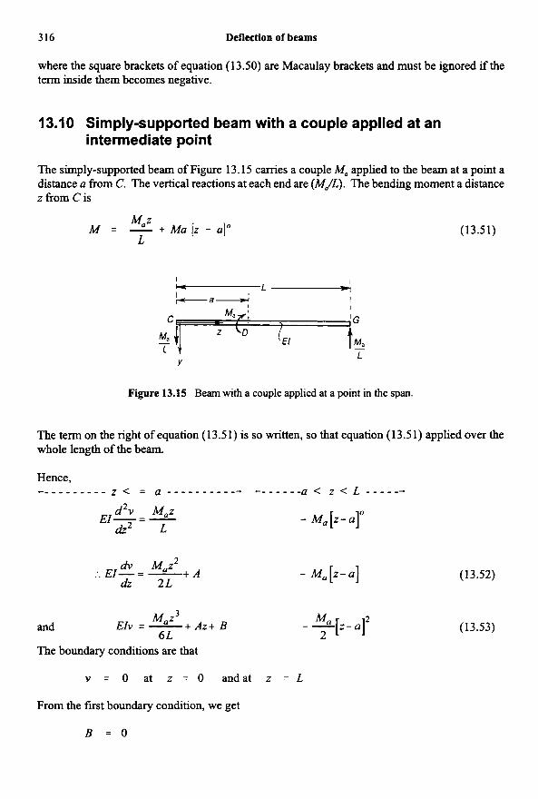
13.10 Simply-supported beam with a couple applied at an intermediate point
The simply-supported beam of Figure 13.15 carries a couple M, applied to the beam at a point a distance u from C. The vertical reactions at each end are (MJL). The bending moment a distance z from C is
(13.51) M 2 M = - + Mu [z - u]" L
Figure 13.15 Beam with a couple applied at a point in the span.
The term on the right of equation (1 3.5 1) is so written, so that equation (1 3.5 1) applied over the whole length of the beam.
Hence, c - - - - - - - - - z < = u - - - - - - - - - - - c - - - - - - a < z < L - - - - - -
d'v Maz E l - = - - Ma [ z - U ] O
dz2 L
dv Maz2 dz 2L
... El - = - + A - M a [ Z - U ] (13.52)
(13.53) Ma 3
- -[z- u]' 2
and
The boundary conditions are that
EIv = - Maz t Azt B 6 L
v = 0 at z = O andat z = L
From the first boundary condition, we get
B = O
Simply-supported beam with a couple applied at an intermediate point 317
From the second boundary condition, we get
M k ' -4 0 = - + AL - (L - a)'
6 2
- M k Ma :. A = - + - (L - a)' 6 2L
Ma - (-L' + 3L' + 30' - 6aL) 6L
=
Ma - (2L' - 6La + 3 ~ ' ) 6L
=
2L2-6La+3a 2 ) +- -";"-[,-a12 6 L 6 L
where the square brackets in equation (13.54) are Macaulay brackets. The deflection at D, when z = a, is
Mila VD = - (L - a) (L - 2 4
3 EIL
(13.54)
(13.55)
Problem 13.3 A steel beam rests on two supports 6 m apart, and carries a uniformly distributed load of 10 kN per metre run. The second moment of area of the cross-section is 1 x m4 and E = 200 GN/m2. Estimate the maximum deflection.
Solution
The greatest deflection occurs at mid-length and has the value given by equation (1 3.16):
= 0.00844 m 5wL4 - 5(100 x 10)) (6)4 y = - -
384EI 384(200 x 10') (1 x lo-))
318 Deflections of beams
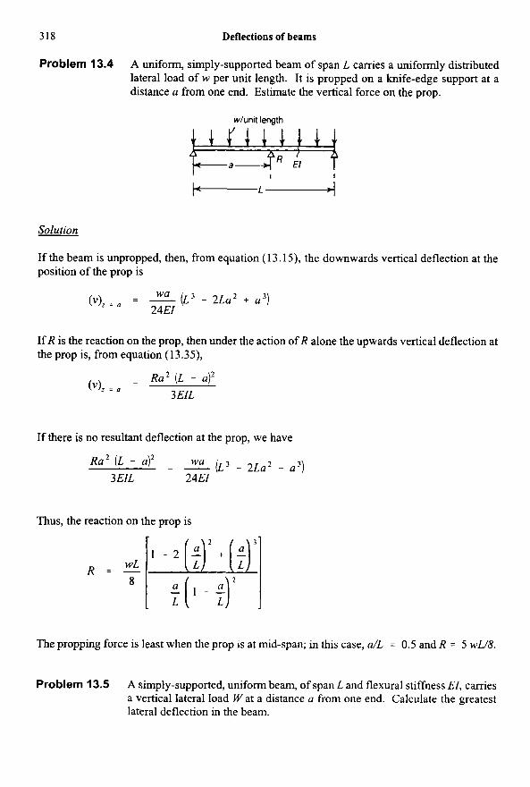
Problem 13.4 A uniform, simply-supported beam of span L carries a uniformly distributed lateral load of w per unit length. It is propped on a knife-edge support at a distance a from one end. Estimate the vertical force on the prop.
WL 8
R = - 1 - 2 [;)2 + [$
E ( , - $ L
Simply-supported beam with a couple applied at an intermediate point 319
Solution
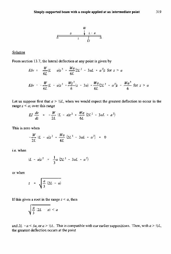
From section 13.7, the lateral deflection at any point is given by
W wa 6L 6L
W wz = wa
EIV = --(L - a)z3 + - b ~ * - ~ U L + a*)z for z > a
wa3 for z > a EIv = --(L - a)z3 +- ( z - 3a) +-(2L2 + a2)z - - 6L 6 6L 6
Let us suppose first that a > %L, when we would expect the greatest deflection to occur in the range z < a; over this range
wa m, W dz 2L 6L
(L - a)z2 + - (2L' - 3aL + a * ) E I - = --
This is zero when
W 2L 6L
-- ( L - a ) z 2 + 5 ( 2 ~ 3 - 3 a ~ + a 2 ) = o
i.e. when
1 3
(L - a)z2 = -a (2LZ - 3aL + a*)
or when
z = 4-
G- If this gives a root in the range z < a, then
- (2L - a) < a
and 2L - a < 3a, or a > %L. This is compatible with our earlier suppositions. Then, with a > %L, the greatest deflection occurs at the point
320 Deflections of beams
1 - z = [(a/3) (2L - a)I2 and has the value
vmax = - w a (2L - a) (L - a) 4- 9LEI
If a < %L, the greatest deflection occurs in the range z > a; in this case we replace a by (L - a), whence the greatest deflection occurs at the point
z = ,/-,andhasthevalue
v,, - - = 9LEI ( L 2 - q- 3 13.11 Beam with end couples and distributed load
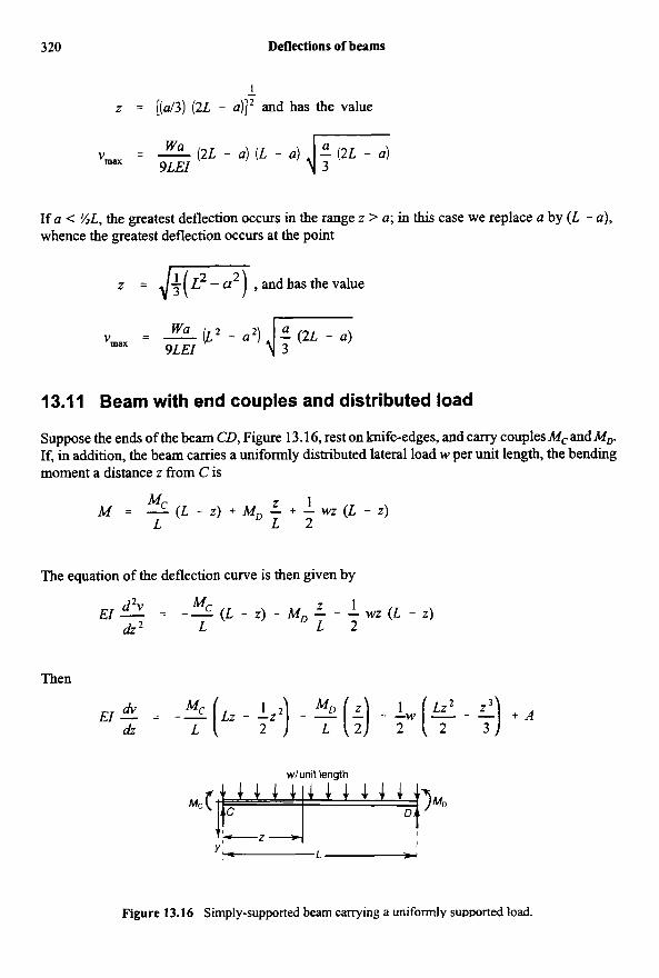
Suppose the ends of the beam CD, Figure 13.16, rest on knife-edges, and carry couples M, and MP If, in addition, the beam carries a uniformly distributed lateral load w per unit length, the bending moment a distance z from C is
Mc z 1 M = - ( L - z ) + M , - + - w z ( L - z ) L L 2
The equation of the deflection curve is then given by
d2v - Mc z 1
d Z 2 L L 2 Ef - - -- ( L - Z ) - MD - - - wz ( L - Z)
Then
E I - * - - - % ( L z - T z 2 ) 1 - ?(:) MD - ? w ( $ 1 - $) + A dZ L
Figure 13.16 Simply-supported beam carrying a uniformly suuuorted load.
Beam with end couples and distributed load 321
and
(13.56)
If the ends of the beam remain at the same level, v = 0 for z = 0 and z = L. Then B = 0 and
Then
+ Z 24
+
The slopes at the ends are
= - L ( 8 4 . + 4MD + wL2) ( z)z=o 24EI
= -- L ( 4 4 + 8MD + wL2) 24EI
Suppose that the end D of the beam now slnks an amount 6 downwards relative to C. Then at v =L we have v = 6, instead of v = 0. In equation (13.56), A is then given by
1 1 1 3 6 24
AL = E16 + -M&’ + -Md2 + -wL4
For the slopes at the ends we have
L 6 = - (8M, + 4MD + wL2) + - (s)z=o 24EI L
6 24EI L
(4Mc + 8M, + wL2) + - L - --
(13.57)
322 Deflections of beams
13.12 Beams with non-uniformly distributed load
When a beam carries a load which is not uniformly distributed the methods of the previous articles can still be employed if M and JMdz are both integrable functions of z, for we have in all cases
d2v dz'
-EI - = M
which can be written in the form
"(") = -- M d z d z EI
If I is uniform along the beam the first integral of this is
m, - = A - ' [ M & EI (13.58) G5
where A is a constant. The second integral is
1 E/
v = AZ + B - - [[Mdzdz (13.59)
If M and J M dz are integrable function of z the process of finding v can be continued analytically, the constants A and B being found from the terminal conditions. Failing this the integrations must be performed graphically or numerically. This is most readily done by plotting the bending- moment curve, and from that deducing a curve of areas representing J M dz. From this curve a third is deduced representing J J M dz dz.
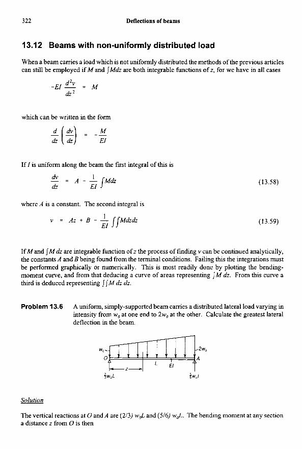
Problem 13.6 A uniform, simply-supported beam carries a distributed lateral load varying in intensity from w, at one end to 2w0 at the other. Calculate the greatest lateral deflection in the beam.
Solution
The vertical reactions at 0 and A are (213) wJ and (516) wJ. The bending moment at any section a distance z from 0 is then
Beams with non-uniformly distributed load 323
2 1 W G 3 M = -w,Lz - T W G ~ - - 3 6L
Then
On integrating once,
where C, is a constant. On integrating further, * + c,z + c2 w&3 W#4 EIv = -IT - - -
24 120L
where C, is a further constant. If v = 0 at z = L, we have
11 180
C, = --w,,L3 and C, = 0
Then
11 W , L Z ~ wG4 wG5 EIv = - w&’z - - - - + -
180 9 24 120L
The greatest deflection occurs at dv/dz = 0, i.e. when
W,LZ* W G 3 W#4 - - 11 w * L 3 - - + - + - -
180 3 6 24L
or when
+ 60(;)3 - 120(;)2 + 22 =
The relevant root of this equation is z/L =OS06 which gives the point of maximum deflection neai to the mid-length. The maximum deflection is
324 Deflections of beams
7.03 w, L4 wo L4 v,, i --- - 0.0195- 360 EI EI
This is negligibly different from the deflection at mid-span, which is 5w0L4
(VIz = L / 2 = - 256EI
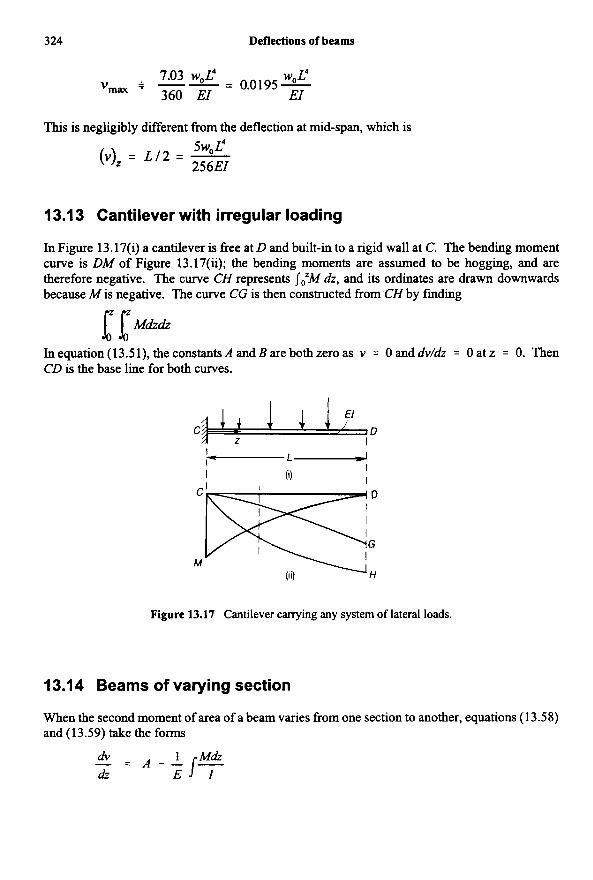
13.13 Cantilever with irregular loading
In Figure 13.17(i) a cantilever is free at D and built-in to a rigid wall at C. The bending moment curve is DM of Figure 13.17(ii); the bending moments are assumed to be hogging, and are therefore negative. The curve CH represents JtM dz, and its ordinates are drawn downwards because M is negative. The curve CG is then constructed from CH by finding
1 [Mi&& Inequation(l3.51),theconstantsAandBarebothzeroas v = Oanddvldz = Oatz = 0. Then CD is the base line for both curves.
Figure 13.17 Cantilever carrying any system of lateral loads.
13.14 Beams of varying section
When the second moment of area of a beam varies from one section to another, equations (1 3.58) and (13.59) take the forms
- - dV - A - L J ? dz E
Cantilever with irregular loading 325
and
v = A z + B - - 1 r,+ E
The general method of procedure follows the same lines as before. If (M/I) and J(M/l)dz are integrable functions of z, then (dv/dz) and v may be evaluated analytically; otherwise graphical or numerical methods must be employed, when a curve of (M/I) must be taken as the starting point instead of a curve of M.
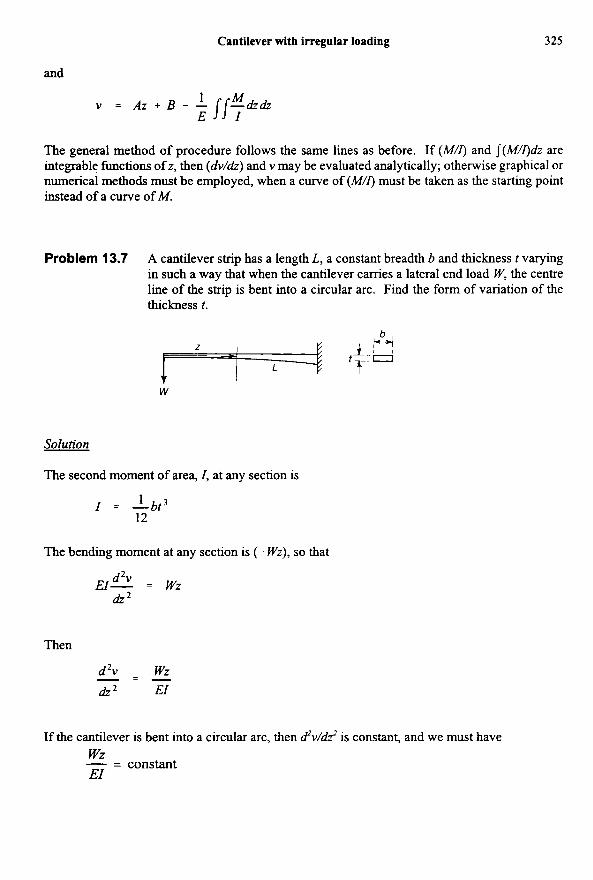
Problem 13.7 A cantilever strip has a length L, a constant breadth b and thickness t varying in such a way that when the cantilever carries a lateral end load W, the centre line of the strip is bent into a circular arc. Find the form of variation of the thckness t.
Solution
The second moment of area, I, at any section is
1 12
I = -bt3
The bending moment at any section is (- Wz), so that
d2v
dz2 El- = WZ
Then
d2v - wz - - - rL2 E l
If the cantilever is bent into a circular arc, then d*v/dZ' is constant, and we must have wz EI - - - constant
326 Deflections of beams
This requires that
Z - - - constant I
or I " 2
Thus, 1 - bt' ot z
12
1 or t " z3
Any variation of the form 1
t = to ($7
where to is the thickness at the built-in end will lead to bending in the form of a circular arc.
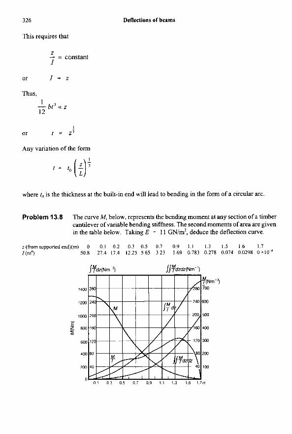
Problem 13.8 The curve M , below, represents the bending moment at any section of a timber cantilever of variable bending stiffness. The second moments of area are given in the table below. Taking E = 11 GN/m2, deduce the deflection curve.
z(frornsupportedend)(rn) 0 0.1 0.2 0.3 0.5 0.7 0.9 1.1 1.3 1.5 1.6 1.7 I (m') 50.8 27.4 17.4 12.25 5.65 3.23 1.69 0.783 0.278 0.074 0.0298 0 x 1 0 ~ 4
Non-uniformly distributed load and terminal couples 321
Solution
The first step is to calculate M/I at each section and to plot the M/I curve. We next plot the area under this curve at any section to give the curve
I
From this, the curve
is plotted to give the deflected form
The maximum deflection at the free end of the cantilever is
300 lo6 = 0.0272 m 1 v = - (300 x lo6) = E 11 x 109
13.1 5 Non-uniformly distributed load and terminal couples; the method of moment-areas
Consider a simply-supported beam carrying end moments M, and M,, as in Figure 13.16, and a distributed load of varying intensity w. Suppose M, is the bending moment at any section due to the load w acting alone on the beam. Then
MD ( L - z ) + - 2 Mc M = M o + - L L
The differential equation for the deflection curve is
The integral between the limits z = 0 and z = L is
(13.60)
(13.61)
328 Deflection of beams
Again, on multiplying equation ( 13.60) by z, we have
But
(13.62)
Thus, on integrating equation (13.62),
(13.63)
But if v = 0 when z = 0 and z =L, then equation (13.63) becomes
Then
MDL M c L 1 Mozdz
: = L 3EI 6EI EIL (13.64)
On substituting this value of (dddz), into equation (13.61),
M,L 1 L 1 L M c L - - - -I Mozdz - -1 M0z& (13.65) (2) :=0 = 6EI El o EIL o
the integral J: Mo dz is the area of the bending moment curve due to the load w alone; M, zdz is the moment of h s area about the end z = 0 of the beam. If A is the area of the bending moment diagram due to the lateral loads only, and z is the distance of its centroid from z = 0, then
A = [Modz , z - = L f M o z d z A
and equations (13.64) and (13.65) may be written
Non-uniformly distributed load and terminal couples 329
(13.66)
(13.67)
The method of analysis, malung use of A and Z, is known as the method of moment-areas; it can be extended to deal with most problems of beam deflections.
When the section of the beam is not constant, equation ( 13.60) becomes
The slopes at the ends of the beam are then given by
and
It is necessary to plot five curves of (Mdl), (l/l), (do, (;/l), (M,@) and to find their areas. As an example of the use of equations (13.66) and (13.67), consider the beam of Figure
13.18(i), which carries end couples, Mc and MD, and a concentrated load Wat a distance a from C. The bending moment diagram for W acting alone is the triangle CBD, Figure 13.18(ii). The
area of this triangle is
w a A = -L - ( L - a ) = - ( L - a ) 2 ' (7) 2
To evaluate its first moment about C, divide the triangle into two right-angled triangles, having centroids at G, and G,, respectively. Then
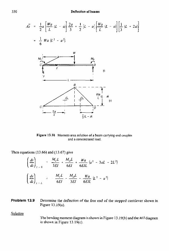
330 Deflection of beams
1 wu 2
1
- Az = --a [ - L (L - .I] $ + + [L - u] [F (L - 41 [; (L + zul]
= - wu ( L z - 2). 6
Figure 13.18 Moment-area solution of a beam carrying end couples and a concentrated load.
Then equations (13.66) and (13.67) give
M& MDL wu - + - + - (a2 - 3aL + 2L2) = (3 = 0 3EI 6EI 6EIL
H=,, - 6EI 3EI 6EIL M 4 - ML4 - wu - - - - -(L? - U Z )
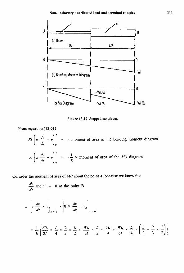
Problem 13.9 Determine the deflection of the free end of the stepped cantilever shown in Figure 13.19(a).
Solution The bending moment diagram is shown in Figure 13.19(b) and the M/I diagram is shown in Figure 13.19(c).
Non-uniformly distributed load and terminal couples 33 1
Figure 13.19 Stepped cantilever.
From equation (13.61)
E1 z - - v = - moment of area of the bending moment diagram ( 2 1: 1 E
L or [ z 5 - V) = -- x moment of area of the MII diagram
0
Consider the moment of area of MI1 about the point A , because we know that
m, - and v = 0 at the point B dz
:. [. d, dv - .] - b x - dv - .A]
z = L dz z = o
- - - x - x - x - + - x - x - + - x - x L 2 L WL L 3 L WL L ($+$.$)I - E 2 1 1 I" 4 3 2 61 2 4 61 4
332 Deflection of beams
or
o+v, = w.'[L+L+L.(;+;)] E1 24 16 24
- &[L+-+- EI 24 16 1 144 5 ,
-
5WL3 V A = -
36EI
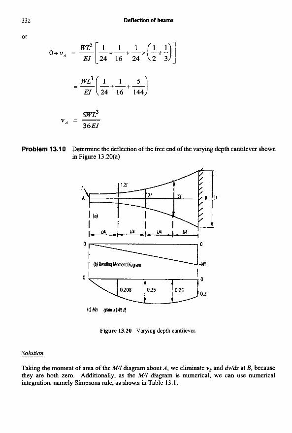
Problem 13.10 Determine the deflection of the free end of the varying depth cantilever shown in Figure 13.20(a)
(c)Mil qramx(Wn)
Figure 13.20 Varying depth cantilever.
Solution
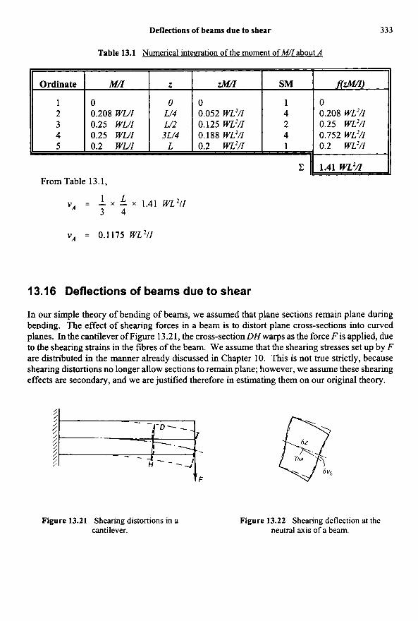
Taking the moment of area of the M/I diagram about A , we eliminate v, and dv/dz at B, because they are both zero. Additionally, as the M/I diagram is numerical, we can use numerical integration, namely Simpsons rule, as shown in Table 13.1.
Deflections of beams due to shear 333
Table 13.1 Numerical intemation of the moment of M/I about A
13.1 6 Deflections of beams due to shear
Ordinate
1 2 3 4 5
In our simple theory of bending of beams, we assumed that plane sections remain plane during bendmg. The effect of shearing forces in a beam is to distort plane cross-sections into c w e d planes. In the cantilever of Figure 13.2 1 , the cross-section DH warps as the force F is applied, due to the shearing strains in the fibres of the beam. We assume that the shearing stresses set up by F are distributed in the manner already discussed in Chapter 10. This is not true strictly, because shearing distortions no longer allow sections to remain plane; however, we assume these shearing effects are secondary, and we are justified therefore in estimating them on our original theory.
Figure 13.21 Shearing distortions in a cantilever.
Mn
0 0.208 WWI 0.25 WL/I 0.25 WWI 0.2 WWI
Figure 13.22 Shearing deflection at the neutral axis of a beam.
Z
z
0 W4 W 2 3L/4
L
1.41w~'fl
From Table 13.1,
ZIMZ
0 0.052 WL'/I 0.125WL2/I 0.188WLZ/I 0.2 wP/z
SM
1 4 2 4 1
f(zMX!-)
0 0.208 wL2/I 0.25 WP/I 0.752 WL'/I 0.2 WL'/I
334 Deflection of beams
Suppose the shearing stress at the neutral axis of the beam is T ~ ” , then the shearing strain at the neutral axis is
T~~
G YN, = - (13.68)
where G is the shearing modulus. The additional deflection arising from shearing of the cross- section is then
sz TN.4
G 6vs = yNA sz = -
Then
For a cantilever of thin rectangular cross-section, Section 10.2,
3F T~~ = - 2ht
where h is the depth of the cross-section, and t is the thickness. Then
*s - 3F - - - a5 2Ght
Then
vs = - 3Fz + A 2Ght
At z = 0, there is no shearing deflection, so A = 0. At the end z = L,
3 FL 2Ght
(VJr. = -
The bending deflection at the free end, z = L, is
FL3 - 4FL 3 E1 Eh 3t
(v),* = - - -
(13.69)
(13.70)
(13.71)
(13.72)
(13.73)
Deflections of beams due to shear
Then the total end deflection is
335
4FL3 3FL VL = -i- Eh3t 2Ght
(13.74)
For most materials (3EBG) is of order unity, so the contribution of the shear to the total deflection is equal approximately to (h/L)’. Clearly, the shearing deflection is important only for deep beams.
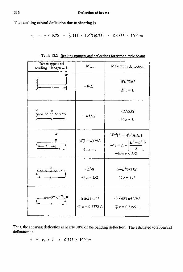
Table 13.2 provides a summary of the maximum bending moments and lateral deflections for some statically determinate beams.
Problem 13.1 1 A 1.5 m length of the beam of Problem 1 1.2 is simply-supported at each end, and carries concentrated lateral load of 10 kN at the mid-span. Compare the central deflections due to bending and shearing.
Solution
From Problem 11.2, the second moment of area of the equivalent steel I-beam is 12.1 x The central deflection due to bending is, therefore,
m4.
wz3 - (10 x lo3) (1.5)3 = 0.290 x m ‘ B = - - 48Es 1, 48 (200 x 10’) (12.1 x
The average shearing stress in the timber is
lo’ = 0.445 MN/m2 (0.15) (0.075)
If the shearing modulus for timber is
4 x lo9 N/m2
the shearing strain in the timber is
336 Deflection of beams
The resulting central deflection due to shearing is
v, = y x 0.75 = (0.111 x lO-3 ) (0.75) = 0.0833 x l O - 3 m
Table 13.2 Bendine moment and deflections for some simple beams
Thus, the shearing deflection is nearly 30% of the bending deflection. The estimated total central deflection is
v = vB + vs = 0.373 x l O - 3 m
Further problems 337
Further problems (answers on page 693)
13.12 A straight girder of uniform section and length L rests on supports at the ends, and is propped up by a third support in the middle. The weight of the girder and its load is w per unit length. If the central support does not yield, prove that it takes a load equal to (5/8)wL.
A horizontal steel girder of uniform section, 15 m long, is supported at its extremities and carries loads of 120 kN and 80 kN concentrated at points 3 m and 5 m from the two ends, respectively. I for the section of the girder is 1.67 x l O - 3 m' and E = 200 GN/m2. Calculate the deflections of the girder at points under the two loads. (Cambridge)
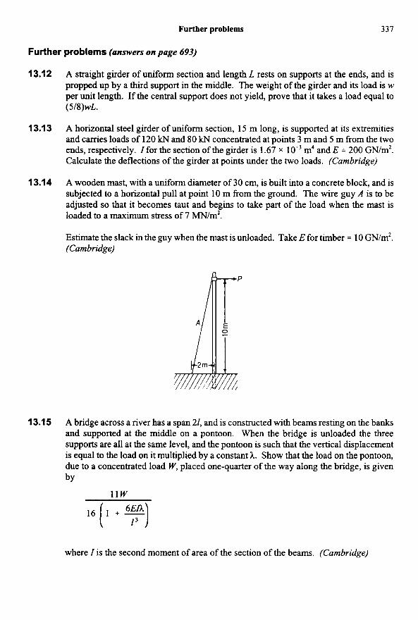
A wooden mast, with a uniform diameter of 30 cm, is built into a concrete block, and is subjected to a horizontal pull at point 10 m from the ground. The wire guy A is to be adjusted so that it becomes taut and begins to take part of the load when the mast is loaded to a maximum stress of 7 MN/m2.
Estimate the slack in the guy when the mast is unloaded. Take E for timber = 10 GN/m*. (Cam bridge)
13.1 3
13.14
13.1 5 A bridge across a river has a span 21, and is constructed with beams resting on the banks and supported at the middle on a pontoon. When the bridge is unloaded the three supports are all at the same level, and the pontoon is such that the vertical displacement is equal to the load on it multiplied by a constant 2.. Show that the load on the pontoon, due to a concentrated load W, placed one-quarter of the way along the bridge, is given by
11w 6EIA
, , ( I + F )
where I is the second moment of area of the section of the beams. (Cambridge)
338 Deflection of beams
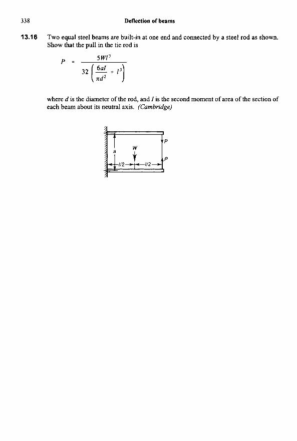
13.1 6 Two equal steel beams are built-in at one end and connected by a steel rod as shown. Show that the pull in the tie rod is
5 W l 3
32 (3 + I)) P =
where d is the diameter of the rod, and 1 is the second moment of area of the section of each beam about its neutral axis. (Cambridge)