Embed Size (px)
Citation preview
a __
Itid
;&3
ELSEVIER
Nuclear Instruments and Methods in Physics Research A 375 (1996) 299-303 NUCLEAR INSTRUMENTS
& METHODS IN PHYSICS RESEARCH
Sectlon A
13 nm advanced SASE free electron laser with a quasi-stable optical klystron configuration
Jizhong Chena,*, Kazuo Imasaki”, Masayuki Fujita”, Makoto Asakawa”, Chiyoe Yamanaka”, Kunioki Mimab, Sadao Nakaib,
“Institute For Laser Technology. Z-6 Yamadaoka, Suita, Osaka, 565, Japan hlnstitute of Laser Engineering, Osaka University . 1-6 Yamadaoka, Suita, Osaka, 565, Japan
Abstract For soft X-ray projection lithography, we propose a 13 nm advanced SASE FEL with a quasi-stable optical klystron
configuration. To shorten the wiggler length and decrease the overall size of the FEL system, we put forward the concept of
quasi-stable operation of an asymmetric optical klystron. With a similar tolerance. our advanced SASE FEL can cut down the magnetic length of a single-pass SASE FEL from 37.12 to 20.3 m at the saturation power 42.8 MW (3D corrected), at the cost of an energy-modulated e-beam bunch and an adjustable dispersion magnet system. The detail analyses are based on the
Pellegrini’s scaling law and the one-dimensional FEL simulation code ILTID.
1. Introduction
Development of free electron lasers (FELs) for VUV (200-10 nm) and X-ray (IO-O. I nm) regions is considered
to be among the most favorable direction. This is because
there exist many application areas of chemistry, physics, biology, and material science for improved photon sources.
A conventional FEL oscillator cannot be operated in the VUV or the soft X-ray region because of the difficulty of mirror fabrication with high normal reflectivity and high power endurance. With the development of accelerator
technology. currently the self-amplified spontaneous emis- sion (SASE) mode attracts much interest. Particularly a 2-4nm high power FEL has been proposed using a 10 GeV/2.5 kA electron beam from the SLAC linac [ 1,2].
In that proposal a 60-70 m long wiggle with the same long external quadrupole lattice for beam focusing and trans-
portation is required. Whether there exists a method to reduce the wiggler length, thereby making the SASE FEL facility more easily realized, attracts our attention. It is very natural to recall the early work on the optical klystron (OK) configuration which was proposed to improve the small signal gain and reduce the X-ray FEL’s wiggler length 131. But that kink of proposal did not obtain
significant attention because of its stringent requirements on the e-beam energy spread. Until now many works on OK oscillator experiments have been done in the visible region [4-71, but few papers are published on numerical demonstration of OK performance and characteristics in the nonlinear region [8-l I].
In this work, we will discuss our 13 nm SASE FEL proposal with a quasi-stable OK configuration which is expected to be able to support high-volume VLSI chip production. Currently the reflectivity of Mo/Si multilayer
soft X-ray mirrors has reached 67% around 13 nm at
normal incidence with a good heat resistance [ 121. 13 nm is regarded as the best wavelength for high resolution
projection lithography because of the easy realization of the optical system.
2. Design considerations
For the design of a I3 nm SASE FEL, we consider using
the scaling law to give an overall estimate about the facility size and the requirements on the electron beam.
Then the results are used as the primary input parameters to start detailed numerical calculations by a powerful one-dimensional code ILTlD. The result of the ID code should be modified by a 3D correction.
-7.1. FEL scaling law
The FEL scaling law of Pellegrini is written very clearly in Ref. [2] and is thought to be a useful tool for a quick review of the FEL performance characteristics. By the combination of the wiggler equation given in Ref. [13] and the following total power equation for a conventional synchrotron radiation source:
* Corresponding author. P, = 3.628 x 10m5(2N- I)E;,,K’l,lh, (kW) (1)
016%9002/96/$15.00 Copyright 0 1996 Elsevier Science B.V. All rights reserved SSDI 016%9002(95)01334-2 V. SHORT WAVELENGTH FELs
300 J. Chrn et al. I Nucl. Imtr. end Meth. in Phvs. Rex. A .77.? (1996) -799%203
curves of characteristic parameters of an FEL. an e-beam,
and the synchrotron source as functions of wiggler period can be shown on our Macintosh computer quickly. With a
trade-off study on the overall size and the requirements on the e-beam, we determined the fundamental parameters of our 13 nm SASE FEL as the following: for the e-beam. E, = 470.8 MeV, rc = 0.25 mm, Ic = 200 A. Ayly = 0.053%: for the wiggler, h, = 1.6 cm, BU = 5.869 KG (K = 0.619). gap = 8 mm: FEL properties, A,_ = 13 nm.
&, = 24.0 m, P,,, = 49.9 MW. corresponding synchrotron
radiation power P,_., = 38.6 W (one-period). and P,,, =
I 15.8 kW (24 m long). It is easily found that for a similar length of uniform wiggler, SASE FEL has a four order of
magnitude higher peak power than that of a synchrotron
source.
2.2. ID .simulation
2.3. 3D sinxdation
TDA code [I41 is used to correct the results of ILTID
code. Limited by our knowledge of its operating technique and the computer availability, the TDA (NEC SAP ver- sion) still could not run well in the short wavelength region
and for an optical klystron. But its sample calculation with the namelist input Newrun provides us a standard to check the ILTID code and correct its results.
3. 1D FEL equations
The 1D equations we used were firstly published in
1981 [ 151. and summarized in Refs. [16,17]. The inclusion of an optical klystron function was finished in Refs. [IO,1 I]. For easy understanding, we write here the 1D FEL equations again as:
dy e\bw - = - ~ sin Vr dz 2Ykw
2w;
(k, + kw )cl Hsin pu-) cos ly - (cos p) sin p} ,
(2)
d4 +d,-’
2e,bu ~ cos k,k,
* >
(3)
(4)
(5)
where E, and B_ are the peak values and the quantity Z,, = 377 0 is known as the wave impedance of free space.
A typical optical klystron configuration consists of three sections, two wigglers and a dispersion space in between. They are called the modulator (B,, and L,, , ), drift section or the buncher (B, and Ld). and the radiator separately (B,+ and L,, 1. The functions of the buncher are to modulate the
electron phases and to accelerate bunching in phase space, and, as a result, to make the FEL power more quickly reach its saturation in a shorter wiggler length. For a
standard magnetic dispersion section for reducing the free- drift space length L,. the phase change is expressed as
7)
For a soft X-ray FEL ( I3 nm). modulation coefficient in Eq. (7) is very big. A very small electron energy modula- tion at the entrance of the buncher can be transferred to a significant phase change at the exit of the buncher. This
makes the free space equivalent to a long wiggler. The FEL radiation power is calculated by
P ou, = A<,(S) = ~rrfO.SZ#fl , (8)
and the power gain is defined as
G = IO log(P<,u,IP,,) (dB) (9)
Tapered wiggler and wiggler error are calculated by the equations in Refs. [ 18.191. All of the above equations are in MKS units.
4. Test of ILTlD code
By the above FEL equations, we developed a new ID FEL code named ILTID. A large time was spent on its correctness tests. It is impossible to simulate all of the electrons in one bunch, which number is as high as to I .25 X IO”’ for a 200 A/ IO ps electron bunch. Only a very
J. Chm rt al. ! Nwl. Instr. arrd h&h. in Phy. Res. A 375 (1996) 299-30.? 301
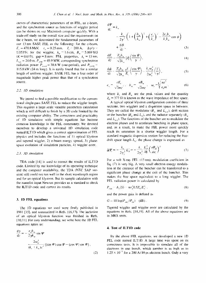
Fig. I. Correction of ILTID code by the result of TDA sample Newmn.
limited number of electrons can be accepted even on the super-computer of ILE especially for the variable parame- ters calculations of an optical klystron. A code test result is shown in Fig. I where different initial simulation particle distributions show totally different power growth perform- ances. The reason is that uniform and random distributions
already introduce some electron bunching effects at the starting point when a small simulation electron number (816) is used. Calculations which show that increasing the
electron number decreases the radiation power show the same fact. A quiet-start method [20] is used to counteract
this initial numerical noise caused by a limited number of simulation particles. The power growth performance ag- rees quite well with the TDA sample result except that the saturation power of ILTID (306 MW) is about 3.5 times higher than that of the TDA sample. So we defined the 16 X 51 quiet start distribution as the basic initial electron distribution (Fig. 7a). We do not correct ILTlD results except as noted. The 3D correction coefficient is 113.5.
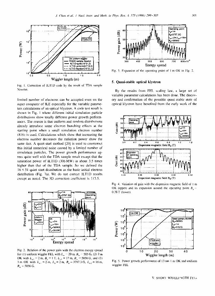
Fig. 2. Relation of the power gain with the electron energy spread
for (I ) uniform wiggler FEL with Lw = 20 m. B, = 585 G, (2) 2 m
OK with L,, =2m,B,=1T.L_,=17m,BU=5856G,and(3)
1 m OK with L_, = 2 m, L, = 2 m, B, = 3797.3 G. Lx2 = 18 m,
Eu = 5856 G.
Fig. 3. Expansion
Energy spread
of the operating point of I m OK in Fig. 2
5. Quasi-stable optical klystron
By the results from FEL scaling law. a large set of variable parameter calculations has been done. The discov- ery and confirmation of the possible quasi-stable state of optical klystron have benefited from the early work of the
0.2 0.4 0.6 0.8 10 t.2
Dispersion magnetic field B,j (T) 1, 1.1.1.1
:. I I,,.,,....,,,,,,,,,.,....I....
0 36 0.38 0.40 0 42
Dispersion magnetic field Bd (T)
Fig. 4. Variation of gain with the dispersion magnetic field of I m
OK (upper) and its expansion around the operating point B, =
0.38 T (lower).
0 10 20 30 40
Wiggler length (m)
Fig. 5. Power growth performance of 13 nm 1 m OK and uniform
wiggler FEL.
V SHORT WAVELENGTH FELs
302 J. Chrn et al. I Nucl. Instr. and Meth. in Phvs. Res. A 375 (1996) 299-30.1
-0.3 -0.2 -0.1
Relative wavelength 0.0 ; 0.2 0.3
A)
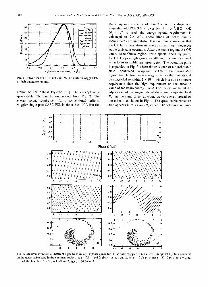
Fig. 6. Power spectra of 13 nm 1 m OK and uniform wiggler FEL
at their saturation points.
author on the optical klystron [21]. The concept of a quasi-stable OK can be understood from Fig. 2. The energy spread requirement for a conventional uniform wiggler single-pass SASE FEL is about 5 X 10V4. But the
stable operation region of 1 m OK with a dispersion magnetic field 3739.3 G is lower than I X 10m5. If 2 m OK (B,, = 1 T) is used, the energy spread requirement is enhanced to 2 X 10 ~‘. These kinds of beam quality requirements are unrealistic. It is common knowledge that
the OK has a very stringent energy spread requirement for stable high gain operation. After the stable region, the OK enters its nonlinear region. For a special operating point,
the OK keeps a high gain peak although the energy spread
is far from its stable operation region. The operating point is expanded in Fig. 3 where the existence of a quasi-stable
state is confirmed. To operate the OK in this quasi-stable region, the electron beam energy spread or the jitter should be controlled to within 1 X IO-’ which is a more stringent requirement than the high requirement on the absolute value of the beam energy spread. Fortunately we found the adjustment of the magnitude of dispersion magnetic field
B, has the same effect as changing the energy spread of the e-beam as shown in Fig. 4. The quasi-stable structure also appears in this Gain-B, curve. The tolerance require-
-3 -2 -1 0 1 2 3
Phase 4 (t-ad)
. . 1 ,.I. - r .._. I . . . . .a
SC
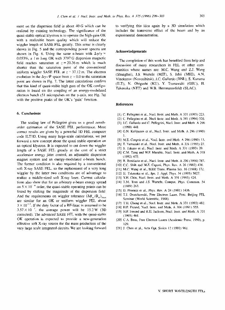
Fig. 7. Electron evolution at different z positions in Ay-IJ phase space for (1) uniform wiggler FEL and (2) 1 m optical klystron operated on the quasi-stable state in the nonlinear region. (a) z = 0.0. 1 and 2: (b) : = 2m,1and2;(c)z=19.56m,I:(d),-=37.12m.1;(e)z=3m, exit of the buncher, 2; (f) ; = II.68 m. 2; (g) z = 20.36m, 2.
J. Chen et al. I Nucl. Instr. and Meth. in Phy. Res. A 375 (1996) 299-303 303
ment on the dispersion field is about 40 G which can be realized by existing technology. The significance of the
quasi-stable optical klystron is to operate the high-gain OK with a realizable beam quality which will reduce the wiggler length of SASE FEL greatly. This sense is clearly shown in Fig. 5 and the corresponding power spectra are shown in Fig. 6. Using the same e-beam with AyIy = 0.053%, a 1 m long OK with 3797 G dispersion magnetic field reaches saturation at ; = 20.36 m which is much shorter than the saturation point of the conventional uniform wiggler SASE FEL at z = 37.12 m. The electron
evolution in the Ay-p space from : = 0.0 to the saturation
point are shown in Fig. 7. The latest calculations confirm that this kind of quasi-stable high gain of the OK configu- ration is based on the coupling of an energy-modulated electron bunch (51 micropulses on the y-axis. see Fig. 7a) with the positive peaks of the OK’s ‘gain’ function.
6. Conclusions
The scaling law of Pellegrini gives us a good zeroth- order estimation of the SASE FEL performance. More
correct results are given by a powerful ID FEL computer code ILTID. Using many large-scale calculations, we put
forward a new concept about the quasi-stable operation on an optical klystron. It is expected to cut down the wiggler length of a SASE FEL greatly at the cost of a strict accelerator energy jitter control, an adjustable dispersion magnet system and an energy-modulated e-beam bunch. The former condition is also required by a conventional soft X-ray SASE FEL, so the replacement of a very long wiggler by the latter two conditions are of advantage to realize a middle-sized soft X-ray laser. Current calcula-
tions also show that for an arbitrary e-beam energy spread on 5 X 10mJ order, the quasi-stable operating points can be found by shifting the magnitude of the dispersion field.
And the requirements on wiggler tolerance (AB,,,IB,),,,
are similar for an OK or uniform wiggler FEL about 3 X 10m7. If the duty factor of a RF-linac is assumed to be 3.57 x lo-‘, the average power will be 15.2 W (3D
corrected). The advanced SASE FEL with the quasi-stable OK operation is expected to provide a new-generation effective soft X-ray source for the mass production of the vary large scale integrated circuits. We are looking forward
to verifying this idea again by a 3D simulation which
includes the transverse effect of the beam and by an
experimental demonstration.
Acknowledgements
The completion of this work has benefited from help and
discussion of many researchers in FEL or other com- munities whose names are: MC. Wang and Z.J. Wang
(Shanghai), J.S. Wurtele (MIT), S. Ishii (MHI), A.N. Vinokurov (Novosibirsk), J.C. Gallardo (BNL), S. Kuruma
(ILT), N. Ohigashi (KU), Y. Tsunawaki (OSU). H. Takenaka (NTT) and W.B. Herrmannsfeldt (SLAC).
References
[1] C. Pellegrini et al., Nucl. Instr. and Meth. A 331 (1993) 223.
[2] C. Pellegrini et al.. Nucl. Instr. and Meth. A 341 (1994) 326.
[3] J.C. Gallardo and C. Pellegrini, Nucl. Instr. and Meth. A 296
(1990) 448.
[4] G.N. Kulipanov et al., Nucl. Instr. and Meth. A 296 (1990)
[5] M.E. Couprie et al.. Nucl. Instr. and Meth. A 296 (I 990) 13.
[6] T. Yamazaki et al.. Nucl. Instr. and Meth. A 331 (1993) 27.
[7] S. Takano et al., Nucl. Instr. and Meth. A 331 (1993) 20.
[S] C.M. Tang and W.P. Marable, Nucl. Instr. and Meth. A 318
(1992) 675.
[9] R. Bonifacio et al., Nucl. Instr. and Meth. A 296 (1990) 787.
[IO] C.C. Shih and M.Z. Caponi, Phys. Rev. A 26 (1982) 438.
[11] M.C. Wang et al., IEEE Trans. Plasma Sci. 16 (1988) 172.
[12] H. Takenaka et al., Jpn. J. Appl. Phys. 34 (1995) 5027.
[13] Y.H. Chin, Nucl. Instr. and Meth. A 331 (1993) 424.
[14] T.M. Tran and J.S. Wurtele, Comput. Phys. Commun. 54
(1989) 263.
[15] D. Prosnitz et al., Phys. Rev. A 24 (1981) 1436.
[16] T.J. Orzechowski, Free Electron Laser, Proc. Beijing FEL
Seminar (World Scientific, 1988).
[17] T.H. Chung et al., Nucl. Instr. and Meth. A 331 (1993) 482.
[IS] H.P. Freund, Nucl. Instr. and Meth. A 304 (1991) 555.
[19] H.P. Freund and R.H. Jackson, Nucl. Instr. and Meth. A 331
(1993) 461.
[20] C.A. Brau, Free Electron Lasers (Academic Press, 1990). p.
129.
[21] .I. Chen et al., Acta Opt. Sinica 12 (1992) 961.
V. SHORT WAVELENGTH FELs