Embed Size (px)
Citation preview
13th April 2007 FFAG 07 Carl Beard
EMMA RF System Carl Beard, Emma Wooldridge, Peter McIntosh, Peter Corlett, Andy Moss,
James Rogers, Joe Orrett
ASTeC, Daresbury Laboratory
•Design Parameters
•Cavity Requirements
•Power Sources
•Distribution options
13th April 2007 FFAG 07 Carl Beard
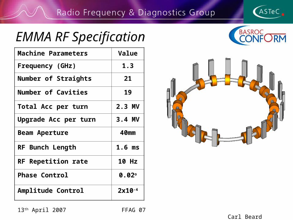
EMMA RF SpecificationMachine Parameters Value
Frequency (GHz) 1.3
Number of Straights 21
Number of Cavities 19
Total Acc per turn 2.3 MV
Upgrade Acc per turn 3.4 MV
Beam Aperture 40mm
RF Bunch Length 1.6 ms
RF Repetition rate 10 Hz
Phase Control 0.02o
Amplitude Control 2x10⁻⁴
13th April 2007 FFAG 07 Carl Beard
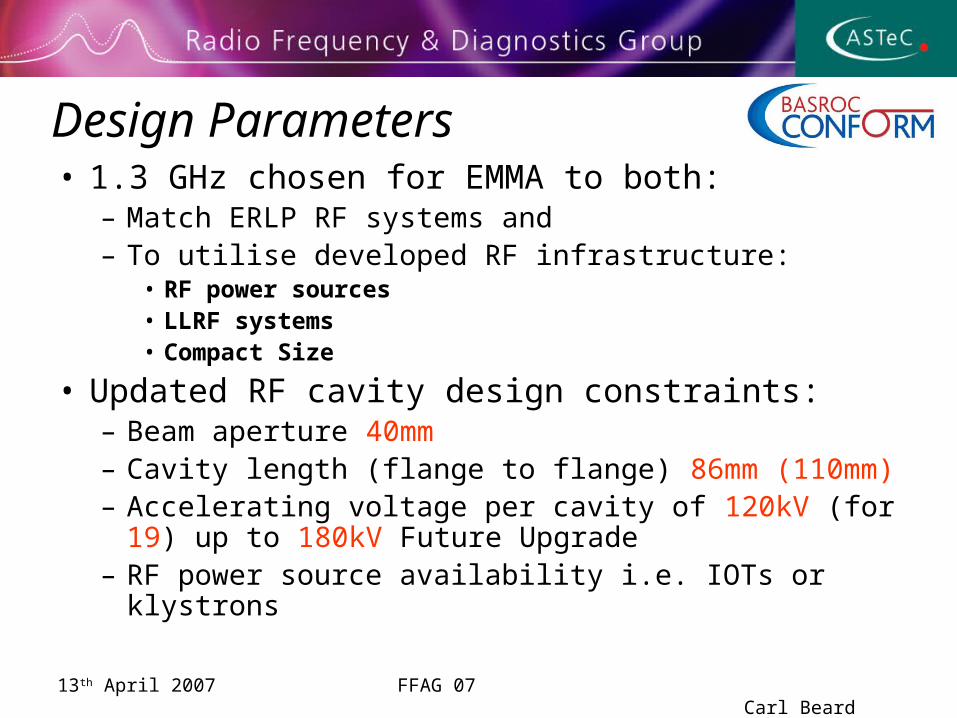
Design Parameters• 1.3 GHz chosen for EMMA to both:
– Match ERLP RF systems and– To utilise developed RF infrastructure:
• RF power sources• LLRF systems• Compact Size
• Updated RF cavity design constraints:– Beam aperture 40mm– Cavity length (flange to flange) 86mm (110mm)– Accelerating voltage per cavity of 120kV (for 19) up to
180kV Future Upgrade– RF power source availability i.e. IOTs or klystrons
13th April 2007 FFAG 07 Carl Beard
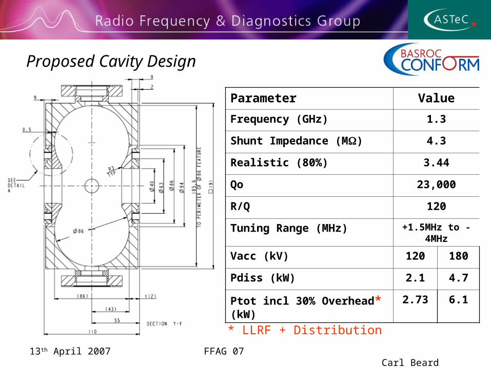
Proposed Cavity Design
Parameter Value
Frequency (GHz) 1.3
Shunt Impedance (M) 4.3
Realistic (80%) 3.44
Qo 23,000
R/Q 120
Tuning Range (MHz) +1.5MHz to -4MHz
Vacc (kV) 120 180
Pdiss (kW) 2.1 4.7
Ptot incl 30% Overhead* (kW) 2.73 6.1
* LLRF + Distribution
13th April 2007 FFAG 07 Carl Beard
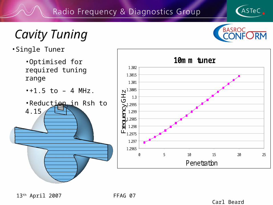
Cavity Tuning
10mm tuner
1.2965
1.297
1.2975
1.298
1.2985
1.299
1.2995
1.3
1.3005
1.301
1.3015
1.302
0 5 10 15 20 25
Penetration
Freq
uenc
y G
Hz
•Single Tuner
•Optimised for required tuning range
•+1.5 to – 4 MHz.
•Reduction in Rsh to 4.15
13th April 2007 FFAG 07 Carl Beard
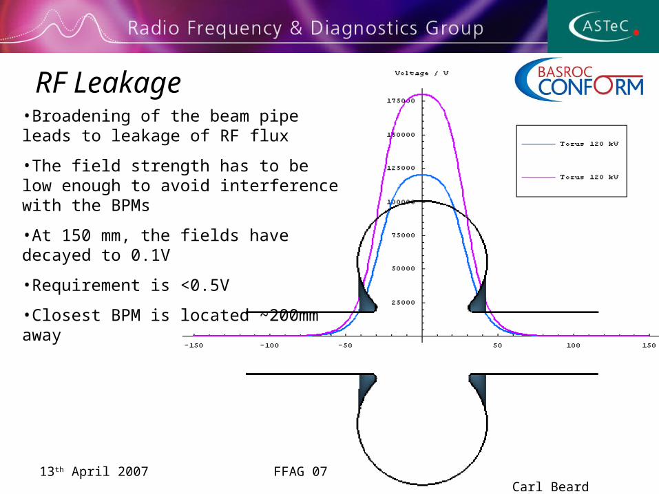
RF Leakage•Broadening of the beam pipe leads to leakage of RF flux
•The field strength has to be low enough to avoid interference with the BPMs
•At 150 mm, the fields have decayed to 0.1V
•Requirement is <0.5V
•Closest BPM is located ~200mm away
13th April 2007 FFAG 07 Carl Beard
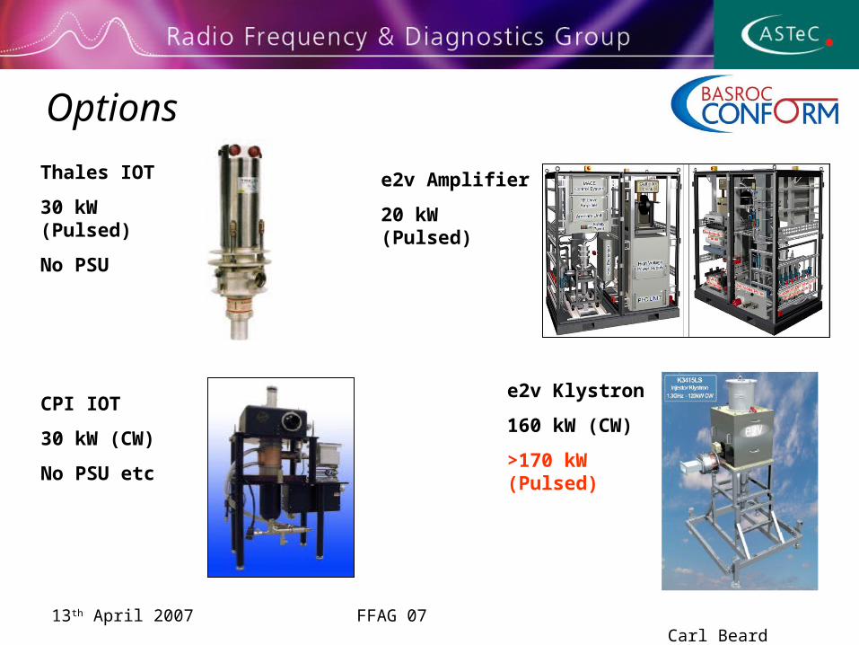
Options
Thales IOT
30 kW (Pulsed)
No PSU
CPI IOT
30 kW (CW)
No PSU etc
e2v Amplifier
20 kW (Pulsed)
e2v Klystron
160 kW (CW)
>170 kW (Pulsed)
13th April 2007 FFAG 07 Carl Beard
IOTs• e2v 116LS
– 16kW CW integrated amplifier system– Dual 19”rack configuration– Integrated HVPS, IOT and controls– Tests at DL in Mar 2006 achieved 20kW pulsed at 1.5ms/20Hz– Multiple IOTs to be powered from 1 PSU
• Thales TH713– 20kW CW independent IOT– Thales are developing an IOT amplifier solution– Tests at Thonon in Sept 2006 achieved 30kW pulsed at
1.5ms/20Hz
• CPI CHK51320W– 30kW CW independent IOT– CPI are developing IOT amplifier solution– >30kW Pulsed should be possible, but no indication of figure
available.
13th April 2007 FFAG 07 Carl Beard
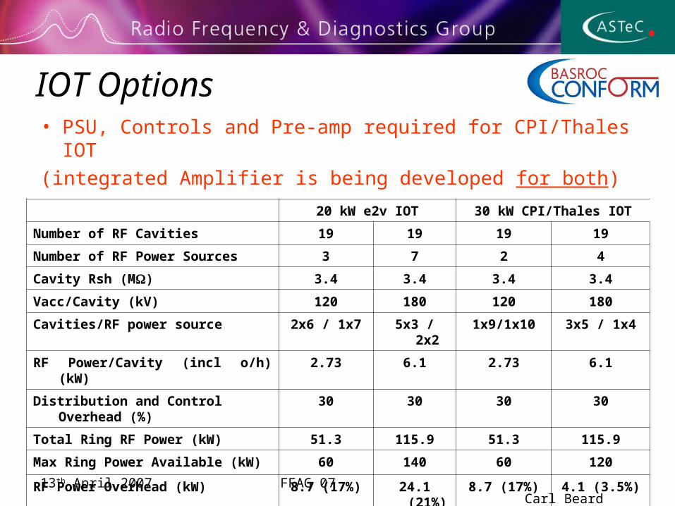
IOT Options• PSU, Controls and Pre-amp required for CPI/Thales IOT
(integrated Amplifier is being developed for both)
20 kW e2v IOT 30 kW CPI/Thales IOT
Number of RF Cavities 19 19 19 19
Number of RF Power Sources 3 7 2 4
Cavity Rsh (M) 3.4 3.4 3.4 3.4
Vacc/Cavity (kV) 120 180 120 180
Cavities/RF power source 2x6 / 1x7 5x3 / 2x2 1x9/1x10 3x5 / 1x4
RF Power/Cavity (incl o/h) (kW) 2.73 6.1 2.73 6.1
Distribution and Control Overhead (%)
30 30 30 30
Total Ring RF Power (kW) 51.3 115.9 51.3 115.9
Max Ring Power Available (kW) 60 140 60 120
RF Power Overhead (kW) 8.7 (17%) 24.1 (21%) 8.7 (17%) 4.1 (3.5%)
13th April 2007 FFAG 07 Carl Beard
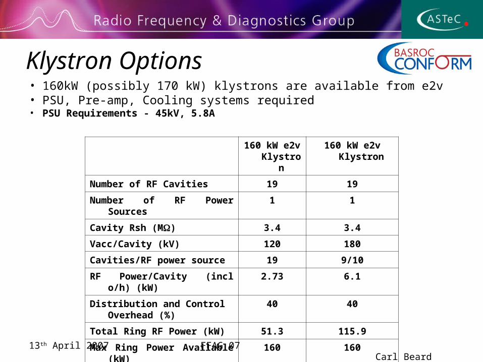
Klystron Options• 160kW (possibly 170 kW) klystrons are available from e2v• PSU, Pre-amp, Cooling systems required• PSU Requirements - 45kV, 5.8A
160 kW e2v Klystron
160 kW e2v Klystron
Number of RF Cavities 19 19
Number of RF Power Sources 1 1
Cavity Rsh (M) 3.4 3.4
Vacc/Cavity (kV) 120 180
Cavities/RF power source 19 9/10
RF Power/Cavity (incl o/h) (kW) 2.73 6.1
Distribution and Control Overhead (%)
40 40
Total Ring RF Power (kW) 51.3 115.9
Max Ring Power Available (kW) 160 160
RF Power Overhead (kW) 78.3 (60%) 44.1 (42%)
13th April 2007 FFAG 07 Carl Beard
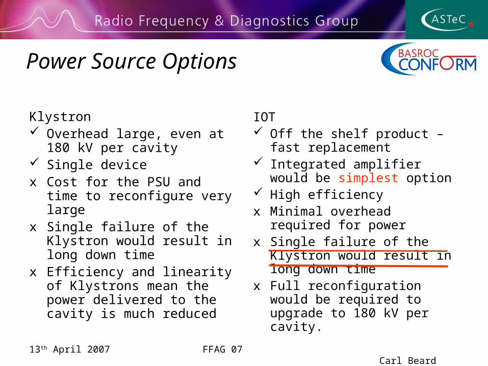
Power Source Options
Klystron Overhead large, even at 180
kV per cavity Single devicex Cost for the PSU and time to
reconfigure very largex Single failure of the Klystron
would result in long down timex Efficiency and linearity of
Klystrons mean the power delivered to the cavity is much reduced
IOT Off the shelf product – fast
replacement Integrated amplifier would be
simplest option High efficiencyx Minimal overhead required for
powerx Single failure of the Klystron
would result in long down timex Full reconfiguration would be
required to upgrade to 180 kV per cavity.
13th April 2007 FFAG 07 Carl Beard
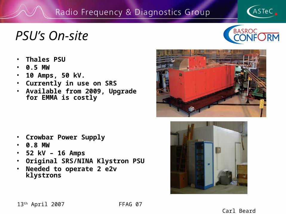
PSU’s On-site
• Thales PSU• 0.5 MW • 10 Amps, 50 kV.• Currently in use on SRS• Available from 2009, Upgrade for
EMMA is costly
• Crowbar Power Supply• 0.8 MW• 52 kV – 16 Amps• Original SRS/NINA Klystron PSU• Needed to operate 2 e2v klystrons
13th April 2007 FFAG 07 Carl Beard
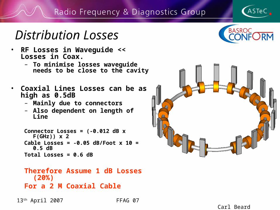
Distribution Losses• RF Losses in Waveguide << Losses in
Coax.– To minimise losses waveguide needs to
be close to the cavity
• Coaxial Lines Losses can be as high as 0.5dB
– Mainly due to connectors– Also dependent on length of Line
Connector Losses = (-0.012 dB x F(GHz)) x 2Cable Losses = -0.05 dB/Foot x 10 = 0.5 dBTotal Losses = 0.6 dB
Therefore Assume 1 dB Losses (20%)For a 2 M Coaxial Cable
13th April 2007 FFAG 07 Carl Beard
7dB
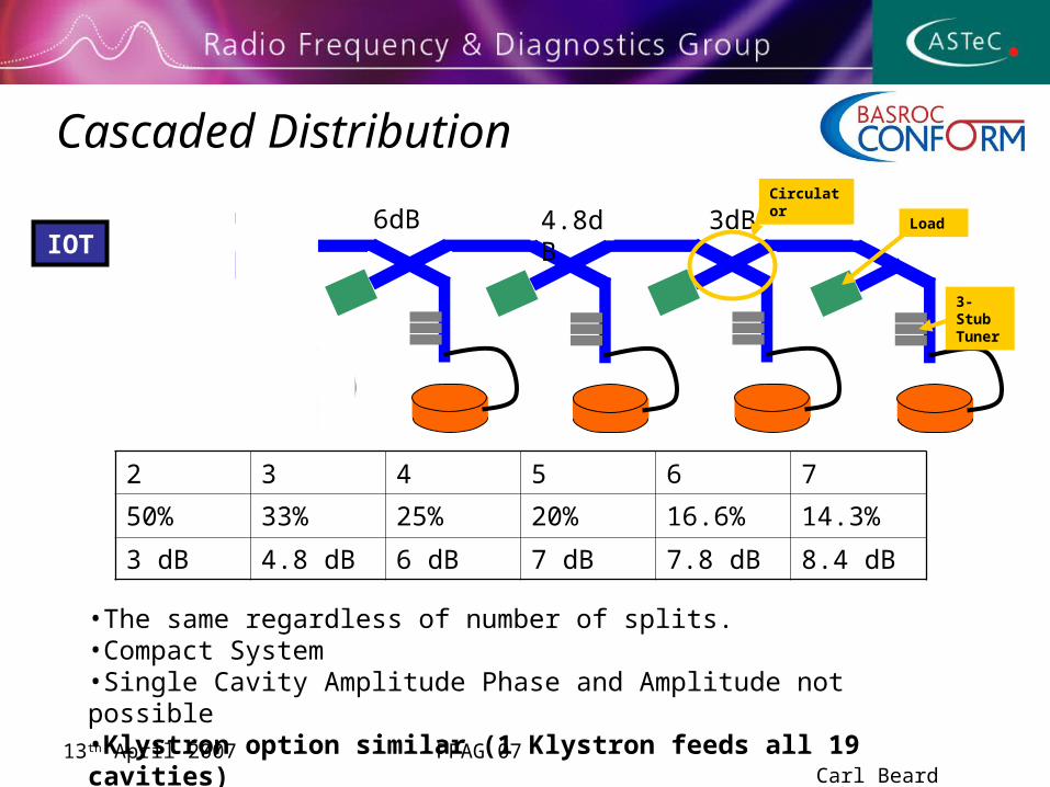
Cascaded Distribution
3-Stub Tuner
2 3 4 5 6 7
50% 33% 25% 20% 16.6% 14.3%
3 dB 4.8 dB 6 dB 7 dB 7.8 dB 8.4 dB
3dB4.8dB6dBIOT
•The same regardless of number of splits.•Compact System•Single Cavity Amplitude Phase and Amplitude not possible•Klystron option similar (1 Klystron feeds all 19 cavities)
Load
Circulator
13th April 2007 FFAG 07 Carl Beard
7dB
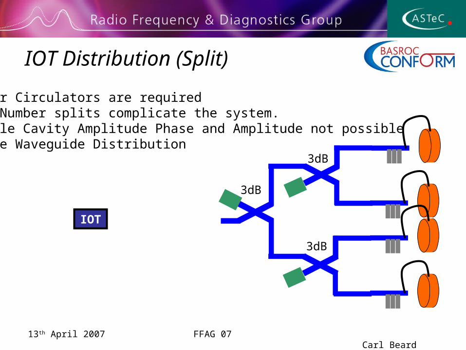
IOT Distribution (Split)
IOT
•Fewer Circulators are required•Odd Number splits complicate the system.•Single Cavity Amplitude Phase and Amplitude not possible •Large Waveguide Distribution
3dB
3dB
3dB
13th April 2007 FFAG 07 Carl Beard
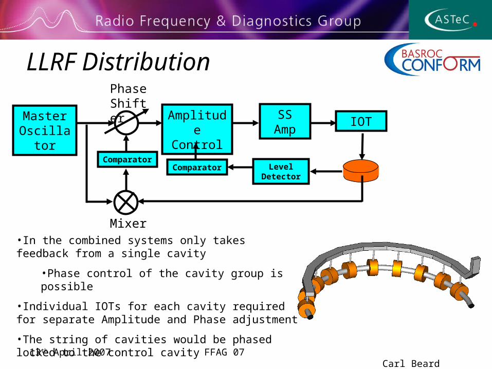
LLRF Distribution
Master Oscillator
Amplitude Control
SS Amp
IOT
Phase Shifter
Mixer•In the combined systems only takes feedback from a single cavity
•Phase control of the cavity group is possible
•Individual IOTs for each cavity required for separate Amplitude and Phase adjustment
•The string of cavities would be phased locked to the control cavity
Comparator Level Detector
Comparator
13th April 2007 FFAG 07 Carl Beard
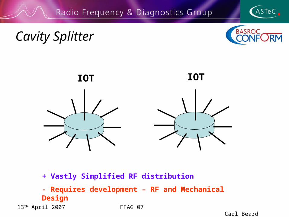
Cavity Splitter
Klystron
+ Vastly Simplified RF distribution
- Requires development – RF and Mechanical Design
IOTIOT
13th April 2007 FFAG 07 Carl Beard
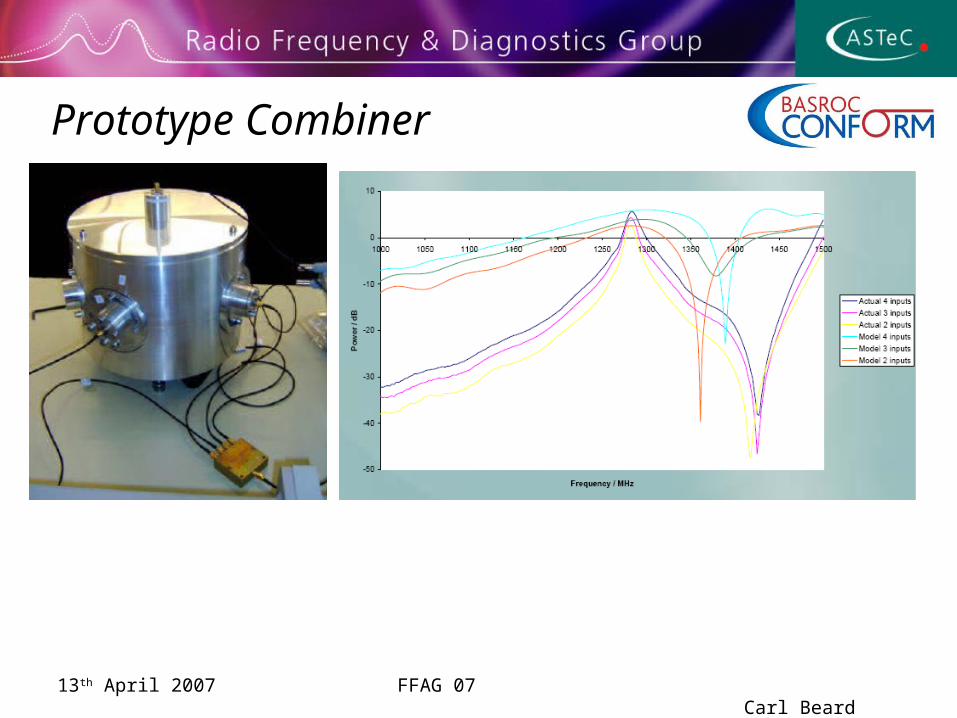
Prototype Combiner
13th April 2007 FFAG 07 Carl Beard
Summary• Cavity has been designed with sufficient tuning range, and
high efficiency to reduce the demand on the RF power requirement
• Fields are sufficiently small to avoid interference with BPMs
• Cascaded RF Distribution would be the optimum since space is valuable.
• Fast, individual cavity amplitude and phase control not possible with this system.
• Slow Phase adjustment is possible through motorised Phase shifters.
• Klystron option would have the highest risk in case of Klystron failure.
• IOT Amplifier option would be the advised option.