Embed Size (px)
Citation preview
1
TECHNICAL PROCUREMENT SPECIFICATION CD-RPH-SB-TPS
PAGE 1 OF 1 R1
TPS No.
CD-RPH-SB-TPS
STATUS ENQUIRY COMMITMENT
ORIGINATING DEPT. ELECTRICAL
P.O / W.O NO.
PROJECT SUPPLY OF 11KV, 630A, 7 PANEL SWITCHBOARD FOR
RESERVOIR PUMP HOUSE SUBSTATION
ITEM 11KV, 7 PANEL SWITCH BOARD
LOCATION RESERVOIR PUMP HOUSE SUBSTATION
CLIENT M/S. FACT COCHIN DIVISION
PURCHASER M/S. FACT COCHIN DIVISION
VENDOR
R1 13.01.2021 REV 1 JJM KPN BKN
REV
NO.
DATE
DESCRIPTION
PREPARED
CHECKED
APPROVED
FACT - COCHIN DIVISION

2
TECHNICAL
PROCUREMENT
SPECIFICATION
ATTACHMENTS
CD-RPH-SB-TPS-ATT
PAGE 1 OF 1 R1
Sl. No. Tag Description
No. of
pages
1 CD-RPH-SB-TPS-SW Scope of work 1
2 CD-RPH-SB-TPS-IS Equipment/ items to be supplied 1
3 CD-RPH-SB-TPS-ES Engineering specification 25
4 CD-RPH-SB-TPS-DS Data sheet 6
5 CD-RPH-SB-TPS-VDSP Vendor data submission procedure 3
6 CD-RPH-SB-TPS-VDR Vendor data requirements 2
7 CD-RPH-SB-TPS-VDI Vendor data index 1
8 CD-RPH-SB-TPS-TCL Technical check list 12
9 CD-RPH-SB-TPS-PF Price format 1
10 CD-RPH-SB-TPS-GRE General requirements for electrics 4
11 CD-RPH-SB-TPS-TP Technical particulars 6
12 CD-RPH-SB-TPS-SIT Scope of inspection and tests 2
13 CD-RPH-SB-TPS-SL Spares list 1
14 CD-RPH-SB-TPS-SVL Sub vendor list 1
15 CD-RPH-SB-TPS-VE Vendor’s experience 1
16 CD-RPH-SB-TPS-CS Compliance statement 1
17 CD-RPH-SB-TPS-TL Typical layout 1
R1 13.01.2021 REV 1 JJM KPN BKN
REV NO.
DATE DESCRIPTION PREPARED CHECKED APPROVED
FACT - COCHIN DIVISION

3
TECHNICAL
PROCUREMENT
SPECIFICATION
SCOPE OF WORK CD-RPH-SB-TPS-SW
PAGE 1 OF 1 R1
TPS NO: CD-RPH-SB-TPS
ITEM: 11KV, 7 PANEL SWITCHBOARD
The Scope of work includes the following
Sl. No.
Description Required Remarks
1.0
Design, engineering, manufacturing, testing at works and
supply of the following medium voltage switchboard fully
conforming to the attached specifications and documents
1.1 11kV, 630A, 26.3kA, SF6/ Vacuum circuit breaker, 7 panel
switchboard for Reservoir Pump House substation. Yes
2.0 Arranging inspection and tests as per “Scope of Inspection & Tests” attached.
Yes
3.0 Supply of spares as per “Spares List” attached. Yes
R1 13.01.2021 REV 1 JJM KPN BKN
REV
NO. DATE DESCRIPTION PREPARED CHECKED APPROVED
FACT - COCHIN DIVISION

4
TECHNICAL
PROCUREMENT
SPECIFICATION
EQUIPMENT/ITEMS TO BE SUPPLIED
CD-RPH-SB-TPS-IS
PAGE 1 OF 1 R1
TPS NO: CD-RPH-SB-TPS
Sl. No.
Description Quantity Remarks
1.0
Design, engineering, manufacturing, testing at works and
supply of 11 kV, 630 A, 26.3 kA SF6/Vacuum circuit
breaker, 7 panel switchboard for Reservoir Pump House
substation, conforming to attached specifications/documents.
1 No.
2.0 Supply of spares for items as per spare list 1 Set
R1 13.01.2021 REV 1 JJM KPN BKN
REV
NO. DATE DESCRIPTION PREPARED CHECKED APPROVED
FACT - COCHIN DIVISION
5
TECHNICAL
PROCUREMENT
SPECIFICATION
RESERVOIR PUMP HOUSE SUBSTATION CD-RPH-SB-TPS-ES
PAGE 1 OF 25 R1
1.0.0 SCOPE OF WORK
1.1.0 This specification covers design, manufacture, shop testing, inspection, packing,
delivery to site of 11 KV, 630 Amps, 26.3 KA, indoor, 7 panel switchboard with
SF6/Vacuum circuit breaker for Reservoir Pump House substation to give reliable and
continuous operation at the load rating specified in the data sheet/ single line diagram.
1.2.0 The equipment offered shall be complete with all parts necessary for their effective and
trouble-free operation. Such parts will be deemed to be within the scope of the supply
irrespective of whether they are specifically indicated in the commercial order or not.
1.3.0 The design of the switchgear should be exclusive and specific responsibility of supplier
and should be comply with current good engineering practice, the relevant codes and
recommendation, the project specific requirements.
2.0.0 REFERENCES
2.1.0 The following documents shall be read in conjunction with this specification.
2.1.1 Engineering specification of general requirements for electrics (Tag no. CD-RPH-SB-
TPS-GRE).
2.1.2 Data sheet of 11 KV, 7 panel switchboard (Tag no. CD-RPH-SB-TPS-DS).
2.1.3 Technical particulars of 11 KV, 7 panel switchboard (Tag no. CD-RPH-SB-TPS-TP).
3.0.0 STANDARDS
3.1.0 Requirements laid down in the latest revisions of the following Indian Standards and
other relevant standards shall be strictly adhered to
IS:13118 Circuit breakers
IS:3427 Metal enclosed switchgear and control gear for
voltages above 1000 V
IS:5578 Guide for marking of insulated conductors
IS:10118 Code of practice for selection, installation and
maintenance of switch gear and control gear
IS:10601 Dimensions of terminals of high voltage switchgear
and control gear
IS:11353 Guide for uniform system of marking and
identification of conductors and apparatus terminals
FACT - COCHIN DIVISION

6
TECHNICAL
PROCUREMENT SPECIFICATION
RESERVOIR PUMP HOUSE SUBSTATION CD-RPH-SB-TPS-ES
PAGE 2 OF 25 R1
IS:722 AC electricity meters
IS:1901 Visual indicator lamps
IEC 60255 Measuring relays and protection equipment
IS:2551 Danger Notice Plates
IS:2705 Current Transformers
IS:3043 Code of practice for earthing
IS:3156 Voltage Transformers
IS:3231 Electrical relays for power systems protection
IS:3842 Application guide for electrical relays for ac
systems IS:4146 Application guide for Voltage Transformers
IS:4201 Application guide for CTs
IS:4483 Flush mounting IDMTL relays
IS:6875 Push buttons and related control switches ( for
voltages up to and including1000Vac and 1200 V
dc )
IS 12729 General Requirements for switchgear and control
gear for voltages exceeding 1000 V
IS 12063 Degree of protection provided for enclosures for
electrical equipment
IS 11353 Guide for Uniform System of Marking and
Identification of Conductors and Apparatus
Terminals
4.0.0 SUPPLY CONDITIONS
4.1.0 The equipment to be supplied shall be designed to operate satisfactorily at rated load under
the supply conditions specified in the data sheet.
FACT - COCHIN DIVISION

7
TECHNICAL
PROCUREMENT SPECIFICATION
RESERVOIR PUMP HOUSE SUBSTATION CD-RPH-SB-TPS-ES
PAGE 3 OF 25 R1
5.0.0 CONSTRUCTION
5.1.0 GENERAL
5.1.1 The switchboard shall be of min. 2mm. thick folded sheet steel construction, fully enclosed,
dust, damp and vermin proof, indoor cubicle type, floor mounted and free standing type,
internal arc tested for designed fault current, fitted with floor rolled truck mounted
SF6/Vacuum circuit breaker in fully horizontal draw out execution and horizontal isolation
type. Vertical units shall be assembled to form a continuous line up of uniform height and
front line-up. Entire panel length shall not be more than 5.25 meter.
5.1.2 SF6/Vacuum circuit breaker shall be truck mounted so that it directly rolls on to the floor
when taken outside without usage of any external breaker handling truck. Cassette type
breakers are not acceptable.
5.1.3 Rated short time withstand current of the switchboard shall not be less than the system short
circuit level specified for 3 seconds. Rated peak withstand current of the switchboard shall
not be less than 2.5 times the system short circuit level.
5.1.4 Degree of protection shall not be less than IP 4X.
5.1.5 The switchboard shall be assembled on suitable base channel of structural steel for proper
erection.
5.1.6 Seal-off bushings should be provided wherever bus bars pass through metallic partitions.
5.1.7 Suitable arc propagation barriers shall be provided between the panels. Explosion vents of
suitable design shall be provided on the roof sheet of the busbar /cable /CT's chambers so as
to enable discharge of explosive gases from inside during a flashover. However the
provision of explosion vent shall not affect the degree of protection/vermin proofing of the
panel.
5.1.8 The panel board shall have adequate width to ensure ease of maintenance. Each cubicle shall
be of compartmentalized construction and shall have following separate compartments.
a) Main compartment for housing the draw out trucks.
b) HV bus bar compartment.
c) Compartment for CT and outgoing cable/bus terminations.
d) LV Compartment
FACT - COCHIN DIVISION

8
TECHNICAL
PROCUREMENT SPECIFICATION
RESERVOIR PUMP HOUSE SUBSTATION CD-RPH-SB-TPS-ES
PAGE 4 OF 25 R1
5.1.9 Front access with hinged doors shall be available to all components in the cubicle, which
require adjustment, maintenance or replacement. Front doors shall be hinged at one end and
shall be bolted (knob type) on the other end. All hinges shall be of concealed design for
elegant appearance.
5.1.10 Rear access shall be available to cable box, cable glands etc. with bolted covers. The rear
panel cover shall be of bolted split type construction (Preferably of two portions) for the
ease of maintenance.
5.1.11 All barriers used shall be manufactured from non-inflammable material. All hardware shall
be corrosion resistant. Door & openings shall be provided with neoprene gaskets.
5.1.12 Switchboard comprising of a number of CB panels, shall be of unit construction to enable
the board to be broken down into sections for shipping to site and to be correctly
reassembled and erected on prepared foundations without skilled supervision. Inter-panel
and inter-compartmental wiring shall preferably be protected by heavy gauge solid metal
conduit or trunk.
5.1.13 The construction of switchboard shall be reliable, safe, self-contained, compact,
interchangeable, accessible, easily extensible at both ends and complete with all positive
mechanical interlocks. Adequate lifting facilities shall be provided on each section.
5.2.0 MOVABLE SECTION
5.2.1 Floor roll out, horizontal draw out horizontal isolation type movable truck of the circuit
breaker shall be mounted on suitable rollers and it shall be complete with circuit breaker
poles, operating mechanism, plug in connectors, etc.
5.2.2 If independent poles are envisaged for the circuit breakers for housing CB contacts and the
rupturing chamber, it shall be fixed to the rigid sheet steel chassis on the movable truck.
5.2.3 Closing and opening mechanism, interlocks, connecting links, coils for close and trip etc.
shall be provided on the movable chassis.
5.2.4 An arrangement in which the panel door is integral with the circuit breaker truck is not
acceptable. It shall be possible to close the panel door after the circuit breaker is fully drawn
out of the panel.
FACT - COCHIN DIVISION

9
TECHNICAL
PROCUREMENT SPECIFICATION
RESERVOIR PUMP HOUSE SUBSTATION CD-RPH-SB-TPS-ES
PAGE 5 OF 25 R1
5.3.0 FRONT COMPARTMENT RECEIVING THE MOVABLE TRUCK
5.3.1 This compartment shall include automatically operated shutters for automatically screening
the stationary plug-in connections with facility for padlocking the shutters in closed position.
5.3.2 The switchgear cubicle shall be provided with a position changing gear arrangement in such
a way that by engaging detachable device from outside the front door, it shall be possible to
move the breaker truck and change position without opening the cubicle door.
5.3.3 Proper guide rails for easy insertion and withdrawal of the circuit breaker shall be provided.
Different positions of the CB like service, test and isolated positions shall be clearly marked.
Adequate barriers shall permit personnel to work safely within an empty breaker
compartment, with the bus bars energized.
5.4.0 CABLE HEAD COMPARTMENT
5.4.1 Cable head compartment of the panel board so designed to receive wound or bar primary
current transformers in addition to cable incoming/ outgoings.
5.4.2 Rear bottom plates of the cable compartment shall be fitted with removable gland plates of
adequate size for fixing the cable glands. Clearances as per standard shall be provided for
11 kV cable termination.
5.4.4 The cable compartment shall be provided at the rear of the switchgear panels suitable for
bottom entry of the cable and shall have sufficient space and support arrangement inside
each panel to accommodate HT cable termination kits and sealing kits suitable for 1Rx3Cx
400 sq: mm Al XLPE cable.
5.4.5 Cable compartment shall be robust enough & self-supporting. The design shall be such that
the weight of the power cable within the compartment shall not cause direct pressure on the
C.T studs.
FACT - COCHIN DIVISION
10
TECHNICAL
PROCUREMENT SPECIFICATION
RESERVOIR PUMP HOUSE SUBSTATION CD-RPH-SB-TPS-ES
PAGE 6 OF 25 R1
5.5.0 BUS BAR COMPARTMENT
5.5.1 Bus bars shall be housed on a separate compartment and shall be accessible for inspection only
with special tools. In the bus bar compartment of the CB, the triple pole bus bars shall be
arranged on supports like araldite epoxy resin, to provide long air insulation distance and
creepage path.
5.5.2 The bus bar compartment shall be provided with bolted covers. Necessary extra precaution
like additional cover, caution signs etc. shall be provided to prevent inadvertent contact with
live bus bars.
5.6.0 LOW VOLTAGE COMPARTMENT
5.6.1 LV compartments containing metering, protection, and control equipment shall be so designed
and constructed, that these shall permit, accessibility for inspection or checking without the
need of de-energizing the switchboard. It shall preferably be mounted on top of the front
compartment receiving the movable section of the CB.
5.6.2 The mounting of the instruments shall be such that vibrations generated by switching
operations do not affect them. Mounting of relays & meters on the rear is not acceptable.
5.6.3 All relays and meters mounted on this compartment shall be flush type and different items
shall be logically laid out on the front of this compartment.
5.6.4 Relays that require adjustment, resetting etc. shall be mounted at reasonable operating height
from the floor level. Maximum operating height shall be 1900 mm and minimum 500 mm
from the floor level.
5.7.0 ACCESSIBILITY
5.7.1 Checking and removal of components shall be possible without disturbing adjacent equipment.
All auxiliary equipment shall be easily accessible.
5.7.2 Access to bus bar chamber, CTs, etc. shall be through rear bolted covers.
FACT - COCHIN DIVISION
11
TECHNICAL
PROCUREMENT SPECIFICATION
RESERVOIR PUMP HOUSE SUBSTATION CD-RPH-SB-TPS-ES
PAGE 7 OF 25 R1
6.0.0 CIRCUIT BREAKER
6.1.0 The circuit breaker shall be of suitable type and rating as mentioned the data sheet and suitable
for indoor use. The CB shall be of three poles, horizontal draw out, horizontal isolation and
floor rollout type unless otherwise specified in the data sheet. The breaker shall be E2, M2
and C2 class type tested. The ratings specified shall be for operating condition inside the
panel, at site.
6.2.0 Rated operating duty shall normally be O-3sec-CO-3min-CO.
6.3.0 Total break time: Less than 75ms.
6.4.0 All parts of the CB shall be liberally dimensioned to have high factor safety to withstand
electrical and mechanical stresses during the normal operation of the breaker and during
short circuits.
6.5.0 Breakers of same rating shall be interchangeable. Wiring and termination of plug-in contacts
shall be identical in all interchangeable breakers.
6.6.0 Non-reset type operation counter shall be provided
6.7.0 CIRCUIT BREAKER CONTACTS
6.7.1 The CB contacts shall be adjustable to allow for wear, be easily replaceable and shall have
the minimum movable parts and adjustments.
6.7.2 The breaker isolating contacts shall be of self-aligning type and shall have ample area and
contact pressure for carrying the rated current and short circuit currents such that there is no
excessive temperature liable to bring about pitting or welding and it shall not show tendency
to “blow off” when carrying rated short circuit currents.
FACT - COCHIN DIVISION
12
TECHNICAL
PROCUREMENT SPECIFICATION
RESERVOIR PUMP HOUSE SUBSTATION CD-RPH-SB-TPS-ES
PAGE 8 OF 25 R1
6.7.3 A minimum of 4 sets of auxiliary contacts are to be provided on breaker operating
mechanism as spare, exclusively for the use of purchaser.
6.7.4 Auxiliary contacts shall have continuous rating of 10A at 240V. Multiplication shall be done
only mechanically. All auxiliary contacts shall be wired to the terminal block. Auxiliary
contacts and limit switches shall be in dust tight enclosures.
6.8.0 OPERATING MECHANISM
6.8.1 The operating mechanism of the CB shall be quick make, quick break type and trip-free as
per relevant code of protection.
6.8.2 Circuit breaker shall be provided with electrically operated motor charged spring closing
mechanism with provision for manual charging through handle. Necessary operating handles
shall also be supplied. The electrical circuit for spring charging motor shall cut off on
initiation of manual charging.
6.8.3 In motor charged spring closing mechanism, the charging of the closing spring shall be
automatically initiated after every closing operation. It shall be ensured that the closing
operation shall be possible only when the springs are fully charged. Suitable protection
circuit, limit switches, etc. shall be provided for protection of the spring charging motor and
to cut out the motor when the springs are fully charged.
6.8.4 The closing solenoids / coils and auxiliary devices shall operate satisfactorily between 85
and 110% of the rated auxiliary supply voltage indicated in the data sheet. Trip coils shall
operate satisfactorily at all voltages between 70% and 110% of the rated auxiliary voltage.
6.8.5 Irrespective of the mode of operation of the breaker, independent manual closing and
tripping arrangements shall also be provided as a standard feature for emergency and testing
purposed.
6.8.6 A mechanical interlock shall be provided for preventing any inadvertent / undesired
operation. For instance, closing the breaker when the springs are being charged, draw out of
breaker while breaker is in closed and service position etc.
FACT - COCHIN DIVISION
13
TECHNICAL
PROCUREMENT SPECIFICATION
RESERVOIR PUMP HOUSE SUBSTATION CD-RPH-SB-TPS-ES
PAGE 9 OF 25 R1
6.8.7 Anti-pumping relay & circuitry/anti pumping feature shall be provided in the closing circuit
of the CB to ensure that it does not re-close automatically after a tripping or in the case of
failure to close, even if the closing impulse is maintained.
6.8.8 The control circuit shall be suitable for local as well as remote control. Each control circuit
tapping shall be provided with fuses.
6.8.9 The control and other auxiliary connections from the CB to the cubicle shall be through
plugs and sockets, mechanically coded, rated for 10A (minimum) / 650V, located at either
ends and connected through flexible jumpers. Provision for locking of control plug to avoid
looseness during operation shall be considered.
6.8.10 The jumper shall have sufficient number of spare cores to utilize all the spare auxiliary
contacts and it shall be long enough to maintain connection in the test position of the truck.
The multi-pin plug provided shall have scraping earth terminals.
6.9.0 CB POSITIONS AND INDICATION
6.9.1 There shall be three distinct positions for circuit breaker, viz. service position, test position
and isolated position and these positions shall be clearly marked and provided with
mechanical stops at each position. Circuit breaker shall be electrically and mechanically trip
free in all positions. The test position shall have locking device. Fully racked in, racked out,
and isolated positions shall also be clearly marked.
6.9.2 It shall be possible to release the mechanical stop of the truck in the test position in order to
draw-out the truck fully after severing the control connections.
6.9.3 Shutters shall automatically screen cable and bus bar isolating connections before the CB
reaches isolation position.
6.9.4 An automatic visual indication shall be provided to indicate spring charged / discharged
positions.
FACT - COCHIN DIVISION
14
TECHNICAL
PROCUREMENT SPECIFICATION
RESERVOIR PUMP HOUSE SUBSTATION CD-RPH-SB-TPS-ES
PAGE 10 OF 25 R1
6.9.5 All circuit breakers shall have mechanical ON/OFF indicator and spring charge indicator.
These shall be visible from the front without opening the panel door. There shall be
provision for mechanical (manual) tripping of breaker and manual charging of the springs
with suitable handle.
6.10.0 POSITIVE INTERLOCKS OF THE CB
6.10.1 It shall not be possible to close the circuit breaker unless it is fully plugged in (truck in
service position) or fully isolated (truck in the test position) or has been completely removed
from the cubicle.
6.10.2 It shall not be possible to discharge the closing spring if the CB is in closed position already.
6.10.3 It shall not be possible to close the circuit breaker unless the closing spring is fully charged.
6.10.4 Interlock shall be provided to prevent pushing in /drawing out of the breaker truck from any
of the three positions to another when the breaker is in the closed position.
6.10.5 Truck cannot be racked into service position with door open and control connection
disengaged. Insertion of breaker into `Service' position shall not be possible if safety
shutters are not free. Door interlock shall have defeat feature.
6.10.6 Control connections cannot be disengaged with the truck in `Service'.
6.10.7 Remote closing of breaker not permitted with door open.
6.10.8 Padlocking facility in test & service position to be made available.
6.10.9 Safety shutters shall be spring loaded, positively operated by the travel of the draw out
truck.
6.10.10 Mechanical and electrical interlocks shall be provided for Incomers and bus coupler Circuit
Breakers for preventing parallel operation of the incomers. Three locks and two keys system
shall be employed. Keys shall be trapped in circuit breaker “CLOSED” condition and free in
circuit breaker “OPEN” condition.
FACT - COCHIN DIVISION
15
TECHNICAL
PROCUREMENT SPECIFICATION
RESERVOIR PUMP HOUSE SUBSTATION CD-RPH-SB-TPS-ES
PAGE 11 OF 25 R1
6.10.11 Safety shutters shall be of metallic having locking facility in the closed position.
Independent operating mechanism for bus side and cable side shutters shall be provided.
Busbar/ cable marking on safety shutters shall be provided.
6.10.12 The above positive mechanical interlocks are the minimum requirements. Manufacturers
can include any other safety interlocks, which may be necessitated by the particular design
feature of the CB.
7.0.0 BUSBARS
7.1.0 The arrangement of bus bars shall be as per relevant standards. All phase bus bars shall be
of uniform cross section throughout the switchboard.
7.2.0 Bus bars shall be of high conductivity aluminium / copper as specified in the data sheet.
Bus bars shall be continuously rated for the rated current and service conditions specified.
7.3.0 Bus bars shall be provided with heat shrinkable, non-tracking, low absorption type PVC
insulated sleeves with full voltage insulation of the switchboard.
7.4.0 Busbar joints and tap-offs shall be shrouded with removable shrouds of full voltage
insulation.
7.5.0 Maximum allowable current density for bus bars shall be 1.25A/mm2 for copper conductor and
0.78A/mm2 for aluminium conductor.
7.6.0 The horizontal and vertical bus bars shall be rated for the same fault level specified in the data
sheet.
7.7.0 Rigid insulating barriers/ protection guards, wire meshes shall be provided between the group
of line bus bars and other parts, so as to eliminate danger to personnel due to accidental
contact.
7.8.0 Thermal design of the bus bars shall be based on installation of the switchgear in poorly
ventilated conditions. The cooling air volume shall take into account only the bus
enclosure.
7.9.0 The busbar supports shall be non-hygroscopic glass reinforced plastic material with anti
tracking features to prevent flashovers. These shall have high tracking index and be
mechanically strong. Hylam is not acceptable.
7.10.0 These insulators shall be of solid core porcelain or epoxy resin cast, with suitable petticoat
design.
FACT - COCHIN DIVISION

16
TECHNICAL
PROCUREMENT SPECIFICATION
RESERVOIR PUMP HOUSE SUBSTATION CD-RPH-SB-TPS-ES
PAGE 12 OF 25 R1
7.11.0 The bus bars and bus supports shall withstand the dynamic, thermal and magnetic stresses
and strains due to the maximum short circuit current corresponding to the fault level
indicated in the data sheet, without any deformation, deterioration or damage.
7.12.0 Suitable provisions shall be made for the expansion and contraction of the bus caused by
temperature variation and due consideration shall be given for reactance, proximity and
skin effects also, while choosing the sizes and spacing of bus bars.
7.13.0 It shall be possible to extend the bus bars on either side without any further fabrication /
modification on the existing bus bars. Removable end covers with fixed nut and bolting
arrangement shall be provided on either end and the ends of the bus bars shall be suitably
drilled.
7.14.0 Appropriate identification marking / labels shall be provided on the bus bars and tapings for distinguishing the various phases.
7.15.0 Due allowance shall be given in the sizing of the bus bars in case of insulated bus bars.
8.0.0 INSTRUMENT TRANSFORMERS
8.1.0 CURRENT TRANSFORMER
8.1.1 CTs shall conform to relevant Indian / International Standards and shall be cast resin
insulated. They shall be mounted on switchgear stationary part.
8.1.2 CTs shall withstand the maximum short circuit current for a minimum of one second and
it shall be designed to withstand stresses resulting from the maximum short circuit
currents.
8.1.3 CTs for metering and protection shall be selected suitably to meet the individual
requirements of meters and relays specified in the data sheet. Low reactance CTs shall be
used for protection.
8.1.4 CTs for metering purposes shall have adequate capacity to cater for 130% of full load
conditions. Instrument security factor for metering CTs shall not be more than 5 and shall
have an accuracy class of 1, unless otherwise specified.
8.1.5 CTs for protection purposes shall have sufficient accuracy, burden and accuracy limit
factor for necessary coordination / discrimination for clearing the faults. Accuracy limit
factor for protection shall not be less than 10 and accuracy class shall be 5P.
FACT - COCHIN DIVISION

17
TECHNICAL
PROCUREMENT SPECIFICATION
RESERVOIR PUMP HOUSE SUBSTATION CD-RPH-SB-TPS-ES
PAGE 13 OF 25 R1
8.1.6 The burden of the CTs shall meet the requirements of relays, instruments and leads
associated with the particular CT including 20% spare capacity.
8.1.7 Separate CTs / cores shall be used for metering and protection. Dual purposes CTs are not
acceptable.
8.1.8 CTs shall be of class E insulation unless otherwise specified.
8.1.9 CTs shall be provided with polarity markings adjacent to terminals, both for primary and
secondary. These shall be legible even after years of service.
8.1.10 Unused CT terminals must be short-circuited.
8.1.11 CTs shall have solidly earthed system.
8.1.12 The CT terminals that have been used shall be provided with links to facilitate shorting as
and when required (when load / burden on CT is disconnected).
8.1.13 All live terminals shall be shrouded to prevent accidental contact.
8.2.0 POTENTIAL TRANSFORMER
8.2.1 PTs shall conform to relevant Indian / International Standards and shall be cast resin
insulated.
8.2.2 PTs shall have suitable accuracy and capacity for the satisfactory operation of the
protection, instrumentation and metering specified in the data sheet / drawings enclosed.
The class of accuracy and the burden on PTs selected shall be adequate for the destined
different purposes.
8.2.3 Potential transformer shall be of ‘fully drew out’ type and shall be provided with HRC fuses
on both HV and LV sides. The draw out mechanism shall disconnect the bus bars and shall
earth the PT primary and secondary terminals. The primary connection shall be
disconnected before the PT or its primary fuses become accessible.
8.2.4 Withdawable type, line potential transformer shall be mounted on top of cable chamber. PT
mounted inside cable chamber is not acceptable.
8.2.5 The primary rated voltage shall be equal to the rated voltage of the system and unless
otherwise specified, secondary voltage shall be 110V.
FACT - COCHIN DIVISION

18
TECHNICAL
PROCUREMENT
SPECIFICATION
RESERVOIR PUMP HOUSE SUBSTATION CD-RPH-SB-TPS-ES
PAGE 14 OF 25 R1
8.2.6 PTs shall have solidly earthed system.
8.2.7 PT shall be of class E insulation unless otherwise specified.
9.0.0 PT SELECTION SCHEME
9.1.0 PT selection scheme shall be provided in the bus coupler panel. PT voltage supply to the
bus sections shall be fed from the respective incomer’s PT secondary in normal conditions.
9.2.0 When entire panel is charged using only one incomer through bus coupler, PT supply to
the entire panel shall be from PT secondary of incomer in charged condition.
9.3.0 It shall be possible to parallel the incomer-1 PT secondary and incomer-2 PT secondary
when both incomers are in parallel condition.
10.0.0 PROTECTION RELAYS
10.1.0 GENERAL
10.1.1 Relays shall conform to relevant Indian / International standards.
10.1.2 Numerical relay shall have control, measurement and supervision.
10.1.3 It shall be back connected, draw out / plug-in type, flush mounted and fitted with dust tight
covers.
10.1.4 Relays shall have a type and make approved by the buyer. List of acceptable makes is
indicated in the data sheet.
10.1.5 Relay shall be compatible with protection CT secondary current of 1A / 5A.
10.1.6 Relays shall be suitable for auxiliary (control) power supply of 110V DC with 70-110%
variation.
10.1.7 Relays voltage input (PT input) shall be 110 volt A.C. supply, obtained from PT selection
scheme.
10.1.8 Relays shall conform to the latest edition of IS: 3231/IEC 60255.
10.1.9 Relays shall not operate at a current equal to or less than the setting. The minimum
operating current shall not exceed 110% of the setting.
FACT - COCHIN DIVISION

19
TECHNICAL
PROCUREMENT SPECIFICATION
RESERVOIR PUMP HOUSE SUBSTATION CD-RPH-SB-TPS-ES
PAGE 15 OF 25 R1
10.1.10 The IDMT characteristic of the relay shall be in complying with IEC curves.
10.1.11 It shall be ensured, by checking with the relay manufacturer, that with the accuracy limit
factor indicate/ chosen, the thermal withstand capability of the relays will not be exceeded
for the fault levels specified.
10.1.12 Relays shall have self monitoring facility and it shall have relay healthy/relay in operation
indication on fascia.
10.1.13 Trip circuits shall automatically break and CT circuit shorted when a relay is withdrawn.
10.1.14 Relay shall have minimum of 8 numbers of programmable binary inputs and
programmable binary outputs.
10.1.15 Relay shall support both the parallel redundancy protocol (PRP) and the high-availability
seamless redundancy (HSR) protocol together with the DNP3, IEC 60870-5-103, Ethernet
IEC-61850 and Modbus protocols.
10.1.16 Relay shall have RS 485 serial communication port and RJ 45 Ethernet communication
port.
10.1.17 Relay shall have LCD/LED display unit, keypads, LED indicators and communication
port for parameter setting, monitoring and controlling the protection relay. Adequate push
buttons shall be provided on the fascia to display and edit the relay settings, to display and
activate the control segment of the relay, to display the relays instrumentation and fault
data and to reset the output relays and LED’s.
10.1.18 The IEC 61850 communication implementation shall support all monitoring and control
functions. Additionally, parameter settings, Programmable LEDs and event lists,
Measurement display, Disturbance records, Fault records, Importing/Exporting
parameters, Report summary etc. can be accessed using the IEC 61850 protocol.
10.1.19 Relay shall have minimum of 8 numbers of programmable LED indications on the front
side.
10.1.20 The vendor shall supply relay software compatible with MS Windows (Win7- 32bit or
Win10-64bit) and provide configuration support during the erection and commissioning of
the switchboard. Relay technical catalogue, operation manuals, brochures etc. shall be
supplied in both hard and soft copies.
10.1.21 All relay terminals shall bring together and wired to separate terminal block.
FACT - COCHIN DIVISION
20
TECHNICAL
PROCUREMENT SPECIFICATION
RESERVOIR PUMP HOUSE SUBSTATION CD-RPH-SB-TPS-ES
PAGE 16 OF 25 R1
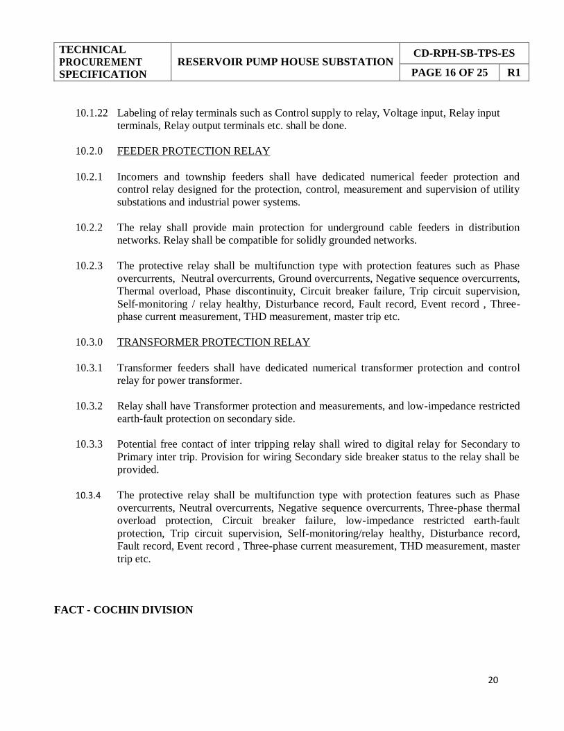
10.1.22 Labeling of relay terminals such as Control supply to relay, Voltage input, Relay input
terminals, Relay output terminals etc. shall be done.
10.2.0 FEEDER PROTECTION RELAY
10.2.1 Incomers and township feeders shall have dedicated numerical feeder protection and
control relay designed for the protection, control, measurement and supervision of utility
substations and industrial power systems.
10.2.2 The relay shall provide main protection for underground cable feeders in distribution
networks. Relay shall be compatible for solidly grounded networks.
10.2.3 The protective relay shall be multifunction type with protection features such as Phase
overcurrents, Neutral overcurrents, Ground overcurrents, Negative sequence overcurrents,
Thermal overload, Phase discontinuity, Circuit breaker failure, Trip circuit supervision,
Self-monitoring / relay healthy, Disturbance record, Fault record, Event record , Three-
phase current measurement, THD measurement, master trip etc.
10.3.0 TRANSFORMER PROTECTION RELAY
10.3.1 Transformer feeders shall have dedicated numerical transformer protection and control
relay for power transformer.
10.3.2 Relay shall have Transformer protection and measurements, and low-impedance restricted
earth-fault protection on secondary side.
10.3.3 Potential free contact of inter tripping relay shall wired to digital relay for Secondary to
Primary inter trip. Provision for wiring Secondary side breaker status to the relay shall be
provided.
10.3.4 The protective relay shall be multifunction type with protection features such as Phase
overcurrents, Neutral overcurrents, Negative sequence overcurrents, Three-phase thermal
overload protection, Circuit breaker failure, low-impedance restricted earth-fault
protection, Trip circuit supervision, Self-monitoring/relay healthy, Disturbance record,
Fault record, Event record , Three-phase current measurement, THD measurement, master
trip etc.
FACT - COCHIN DIVISION
21
TECHNICAL
PROCUREMENT SPECIFICATION
RESERVOIR PUMP HOUSE SUBSTATION CD-RPH-SB-TPS-ES
PAGE 17 OF 25 R1
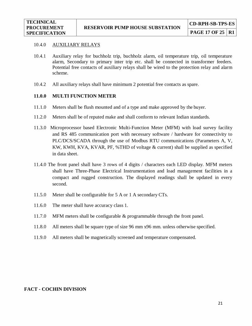
10.4.0 AUXILIARY RELAYS
10.4.1 Auxiliary relay for buchholz trip, buchholz alarm, oil temperature trip, oil temperature
alarm, Secondary to primary inter trip etc. shall be connected in transformer feeders.
Potential free contacts of auxiliary relays shall be wired to the protection relay and alarm
scheme.
10.4.2 All auxiliary relays shall have minimum 2 potential free contacts as spare.
11.0.0 MULTI FUNCTION METER
11.1.0 Meters shall be flush mounted and of a type and make approved by the buyer.
11.2.0 Meters shall be of reputed make and shall conform to relevant Indian standards.
11.3.0 Microprocessor based Electronic Multi-Function Meter (MFM) with load survey facility
and RS 485 communication port with necessary software / hardware for connectivity to
PLC/DCS/SCADA through the use of Modbus RTU communications (Parameters A, V,
KW, KWH, KVA, KVAR, PF, %THD of voltage & current) shall be supplied as specified
in data sheet.
11.4.0 The front panel shall have 3 rows of 4 digits / characters each LED display. MFM meters
shall have Three-Phase Electrical Instrumentation and load management facilities in a
compact and rugged construction. The displayed readings shall be updated in every
second.
11.5.0 Meter shall be configurable for 5 A or 1 A secondary CTs.
11.6.0 The meter shall have accuracy class 1.
11.7.0 MFM meters shall be configurable & programmable through the front panel.
11.8.0 All meters shall be square type of size 96 mm x96 mm. unless otherwise specified.
11.9.0 All meters shall be magnetically screened and temperature compensated.
FACT - COCHIN DIVISION

22
TECHNICAL
PROCUREMENT SPECIFICATION
RESERVOIR PUMP HOUSE SUBSTATION CD-RPH-SB-TPS-ES
PAGE 18 OF 25 R1
12.0.0 ANNUNCIATION SCHEMES
12.1.0 Separate visual and audible annunciation scheme shall be available for
a) Automatic tripping on fault and Non-trip alarm conditions
b) D.C. failure condition
12.2.0 DC failure relay, Alarm accept/reset relay, flasher relay, hooter, buzzer, push buttons, etc
for the alarm scheme shall be mounted on the bus coupler panel.
12.3.0 Accept, Reset and Test Push Buttons for both annunciation schemes shall be provided at
bus coupler panel and labeled clearly.
12.4.0 AUTOMATIC TRIPPING ON FAULT AND NON-TRIP ALARM CONDITIONS
12.4.1 Each protection relays trip and alarm contacts shall be wired to the scheme.
12.4.2 A 15 window annunciation panel shall be provided on the bus coupler panel. Following
details shall be displayed in the windows
a) Incomer-1 Trip
b) Incomer-2 Trip
c) RPH TR-1 Auto Trip
d) RPH TR-2 Auto Trip
e) RPH TR-1 Inter Trip
f) RPH TR-2 Inter Trip
g) Lakeview-RPH S/S link feeder Trip
h) Type III S/S feeder Trip
i) RPH TR-1 Oil/winding temp high alarm
j) RPH TR-2 Oil/winding temp high alarm
k) 5 Windows- Spare
12.4.3 In the event of a fault/alarm, respective protection relay shall initiate Trip and Non-Trip
alarm annunciation scheme in bus coupler panel. The respective window in the 15 point /
channel alarm fascia shall start flashing on the flasher bus (derived from flasher relay) and
the hooter start sounding. When the alarms accept PB is pressed the hooter shall stop and
the fascia window shall glow steady. After resetting the flags and contacts on the
protective relay which initiated the alarm, the alarm scheme can be reset by pressing the
reset. Now the window, which was glowing steady till then, shall go off.
FACT - COCHIN DIVISION

23
TECHNICAL
PROCUREMENT SPECIFICATION
RESERVOIR PUMP HOUSE SUBSTATION CD-RPH-SB-TPS-ES
PAGE 19 OF 25 R1
12.4.4 The Trip and Non-Trip alarm annunciation scheme shall be rated for 110 V D.C. auxiliary
supply.
12.4.5 The annunciation scheme shall be repetitive and shall be ready to receive and initiate
systematically a second or third fault, irrespective of whether the alarm due to first or
second fault in other panels is in ’initiated’ or ’accepted’ or ‘relay reset’ condition prior to
fully resetting of the annunciation scheme.
12.4.6 It shall be possible to check the healthiness of fascia windows by pressing the lamp test
PB.
12.5.0 D.C. FAILURE CONDITION
12.5.1 Instantaneously operated DC under voltage relay shall be connected to the DC input to the
panel. In case of DC failure, the relay shall initiate D.C. failure annunciation scheme. The
indicating lamp comes ON and the buzzer is initiated. On pressing the ’accept’ PB, the
buzzer shall stop. When DC is restored, the relay and annunciation scheme shall get
automatically reset.
12.5.2 The D.C. failure annunciation scheme shall be rated for 230 V A.C. auxiliary supply
obtained from PT selection scheme.
12.5.3 The DC failure sensing relay shall have hand reset flag indication
12.5.4 It shall be possible to test the whole DC failure scheme. A push button shall be provided in
the sensing relay circuit to simulate DC failure and test the scheme.
13.0.0 PUSH BUTTON
13.1.0 Colour of push button knobs shall be as per relevant Indian Standard.
13.2.0 All push buttons shall be provided with legend plates to identify the function or operation.
13.3.0 Push button shall have contacts rating of 6A
FACT - COCHIN DIVISION

24
TECHNICAL
PROCUREMENT SPECIFICATION
RESERVOIR PUMP HOUSE SUBSTATION CD-RPH-SB-TPS-ES
PAGE 20 OF 25 R1
14.0.0 INDICATING LAMPS
14.1.0 Indication circuit shall be through separate contacts only.
14.2.0 Indicating lamps shall be of cluster LED type.
14.3.0 All lamps shall be indigenously available and rated for 7 watts maximum. All signaling
lamps must have clarity of colour.
14.4.0 Lens for signaling lamps shall be so designed to prevent glare from the bulb and it shall
be of dome shape to permit visibility from all directions. The material of lens should be
such that it neither gets destroyed nor changes the colour due to heat from the bulb.
14.5.0 Necessary protective fuses shall be provided for the lamp circuit.
15.0.0 ANTICONDENSATION HEATER
15.1.0 Three nos. of space heaters with thermostat control shall be provided. One each for the
breaker chamber, bus bar chamber and the CT/cable chamber along with a common MCB
mounted inside LT control wiring.
15.2.0 Heater shall be provided inside the panel in easily accessible position for removal /
replacement.
15.3.0 Wiring of space heater shall be isolated or separately bundled from other internal wiring.
16.0.0 CABLE TERMINATION & WIRING
16.1.0 CONTROL CABLE TERMINATION
16.1.1 Termination of wiring for external connection shall be done using terminals of reputed
make and of proven design for long trouble free life.
16.1.2 Terminals shall be compact and shall have very high dielectric strength so as to prevent
flashover and have thermal strength to prevent deterioration.
16.1.3 The moulding material of the terminal body shall preferably be melamine formaldehyde
having high anti-tracking properties.
FACT - COCHIN DIVISION

25
TECHNICAL
PROCUREMENT SPECIFICATION
RESERVOIR PUMP HOUSE SUBSTATION CD-RPH-SB-TPS-ES
PAGE 21 OF 25 R1
16.1.4 Identification/ numbering/ lettering shall be provided for each terminal. Such marks shall
be legible even after years of service.
16.1.5 Minimum 20% spare terminals shall be provided on each terminal block.
16.1.6 Facilities shall be available for temporary or permanent short-circuiting of terminals for
earthing and testing.
16.1.7 Shorting links shall be provided for all CT terminals.
16.1.8 Conductors shall be terminated with adequately sized compression type tinned copper lugs
for connection to equipment terminals and strips. Stranded conductors shall be soldered at
the ends before connection are made to the terminals.
16.1.9 All auxiliary equipment terminals shall be made with pressure type terminals.
16.1.10 Terminal strips shall be preferably separated from power circuits by metal barriers or
enclosures.
16.1.11 All terminals shall be shrouded with plastic covers to prevent accidental contact.
16.1.12 Sufficient clearance shall be available between terminals where terminal lugs are fitted to
them.
16.1.13 Terminals shall be designed to avoid bimetallic corrosion and breaking of strands due to
excess pressure.
16.1.14 Terminal strip for outgoing control cable connections shall be accessible to facilitate
working and testing with breaker in test / service condition and while the switchboard is
energized.
16.1.15 Control terminals for external termination shall be located in the relay compartment only.
All terminals going out of the switchboard shall be brought to a separate terminal board
marked "External Termination". These will be easily accessible.
16.1.16 Complete control wiring shall be done with round lugs only.
FACT - COCHIN DIVISION

26
TECHNICAL
PROCUREMENT SPECIFICATION
RESERVOIR PUMP HOUSE SUBSTATION CD-RPH-SB-TPS-ES
PAGE 22 OF 25 R1
16.2.0 WIRING
16.2.1 Control and power wiring shall be kept separate.
16.2.2 All CT wiring shall be carried out with copper conductor of size not less than 2.5mm2.
16.2.3 Wiring shall be terminated in easily accessible terminal blocks.
16.2.4 The wires shall be arranged neatly and the two ends of each wire and the terminal blocks
shall bear the circuit number by using unbreakable ferrules for identification purposes.
16.2.5 Control wiring wherever terminated shall be in single layer formation.
16.2.6 All inter panel control wiring shall be taken through PVC sleeves and this shall be done by
the switchgear manufacturer with proper identification of wires and terminals for
interconnection.
16.2.7 Whenever a PT is mounted in the breaker carriage, all auxiliary wiring shall be done in
conduits.
16.2.8 All spare contacts of aux. relays, timers, etc. shall be wired up to the terminal block.
17.0.0 INSULATION
17.1.0 The insulation between phases and between phases & ground for power or control
conductors shall be made of suitable insulating material resistant to heat, dust and
dampness. It shall be non-hygroscopic, mould proof and treated with suitable varnishes.
17.2.0 Minimum clearance between phases, or between connections of same phases separated
electrically from each other, or between phases and ground, shall be as per relevant
standards.
FACT - COCHIN DIVISION
27
TECHNICAL
PROCUREMENT SPECIFICATION
RESERVOIR PUMP HOUSE SUBSTATION CD-RPH-SB-TPS-ES
PAGE 23 OF 25 R1
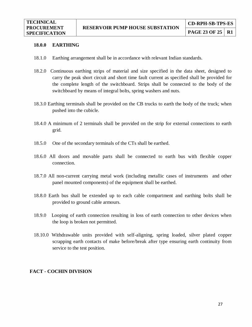
18.0.0 EARTHING
18.1.0 Earthing arrangement shall be in accordance with relevant Indian standards.
18.2.0 Continuous earthing strips of material and size specified in the data sheet, designed to
carry the peak short circuit and short time fault current as specified shall be provided for
the complete length of the switchboard. Strips shall be connected to the body of the
switchboard by means of integral bolts, spring washers and nuts.
18.3.0 Earthing terminals shall be provided on the CB trucks to earth the body of the truck; when
pushed into the cubicle.
18.4.0 A minimum of 2 terminals shall be provided on the strip for external connections to earth
grid.
18.5.0 One of the secondary terminals of the CTs shall be earthed.
18.6.0 All doors and movable parts shall be connected to earth bus with flexible copper
connection.
18.7.0 All non-current carrying metal work (including metallic cases of instruments and other
panel mounted components) of the equipment shall be earthed.
18.8.0 Earth bus shall be extended up to each cable compartment and earthing bolts shall be
provided to ground cable armours.
18.9.0 Looping of earth connection resulting in loss of earth connection to other devices when
the loop is broken not permitted.
18.10.0 Withdrawable units provided with self-aligning, spring loaded, silver plated copper
scrapping earth contacts of make before/break after type ensuring earth continuity from
service to the test position.
FACT - COCHIN DIVISION

28
TECHNICAL
PROCUREMENT SPECIFICATION
RESERVOIR PUMP HOUSE SUBSTATION CD-RPH-SB-TPS-ES
PAGE 24 OF 25 R1
19.0.0 PAINTING AND LABELING
19.1.0 All metal parts of the panel to undergo surface treatment that includes derusting, cleaning
chemically, degreasing, pickling in acid, cold rinsing, phosphating and passivating
followed by spraying with two coats of zinc oxide primer and baking in oven or sheet shall
be Aluzinc.
19.2.0 The sheet steel housing and all the metal surfaces shall be properly cleaned and coated
with two coats of anticorrosive paint over two coats of suitable primer. A final coat in
gloss finish with a colour indicated shall also be given to the switchboard.
19.3.0 All panels shall have, on the front and the rear sides, nameplates in large sized letters,
giving feeder details.
19.4.0 Painted mimic diagram shall be provided on all the panels of the switchboard, unless
otherwise specified in the data sheet.
19.5.0 Nameplates shall be fastened by screws and not by adhesives.
19.6.0 Special warning plates shall be provided on all removable covers or doors giving access to
high voltage cables/ bus bars and inside the switchboard also wherever considered
necessary.
19.7.0 Nameplates shall be of white Perspex acrylic sheet with letters engraved in black.
19.8.0 A nameplate with the switchgear designation shall be fixed at the top of the central panel.
19.9.0 Bus side and cable side shutters shall be labeled for identification.
19.10.0 Nameplates shall be provided for all Door/front mounted devices such as lamps, PBs,
switches, relays, aux. contactors etc., directly below them, giving the nomenclature and
purpose of the device.
19.11.0 Labels shall be made of non-rusting metal with engraved inscriptions of white letters on
black background.
19.12.0 The size of the letters giving switchboards designation shall be 25 mm that for feeder
details 20mm and for components 6mm, unless otherwise specified in the data sheet.
FACT - COCHIN DIVISION

29
TECHNICAL
PROCUREMENT SPECIFICATION
RESERVOIR PUMP HOUSE SUBSTATION CD-RPH-SB-TPS-ES
PAGE 25 OF 25 R1
19.13.0 Label designation and size of lettering subject to approval.
20.0.0 FOUNDATION BOLTS
20.1.0 Necessary foundation channels (if not integral), bolts and nuts shall be supplied along with
the equipment.
21.0.0 TEST CORDS AND TESTING PLUGS
21.1.0 Flexible test cord 2m long with plug and socket for testing the breakers in the withdrawn
position shall be supplied in a separate case. Alternatively flexible cord used for test
position shall have sufficient extra length to test the breaker in the withdrawn position
also.
21.2.0 Earthing and testing plugs for cables and busbars shall be supplied in a separate box.
22.0.0 SPARES AND SPECIAL TOOLS
22.1.0 Spare parts and special tools recommended for keeping stock for trouble free operation of
CB panel for a minimum period of 2 years shall be supplied. List and catalogue numbers
of these spare parts shall also be furnished.
23.0.0 DRAWINGS
23.1.0 All drawings and documents as per Vendor Data Requirement shall be furnished. The
control circuits shall be prepared by the manufacturer and the drawings shall be neat,
legible and incorporating all requirements. The rating of all components such as voltage,
ampere and wattage/VA shall be clearly indicated in component list.
24.0.0 DEVIATION FROM SPECIFICATION
24.1.0 Should the tender wish to deviate from the provisions of the specifications, either on
account of manufacturing practice or any other reasons, he shall draw attention to the
proposed point of deviation in the tender and submit such full information, drawing and
specification so that merits of his proposal may be fully understood. The specification
shall be held binding unless the deviations have been fully accepted as requested.
FACT - COCHIN DIVISION
30
DATA SHEET
RESERVOIR PUMP HOUSE SUBSTATION
CD-RPH-SB-TPS-DS
PAGE 1 OF 6 R1
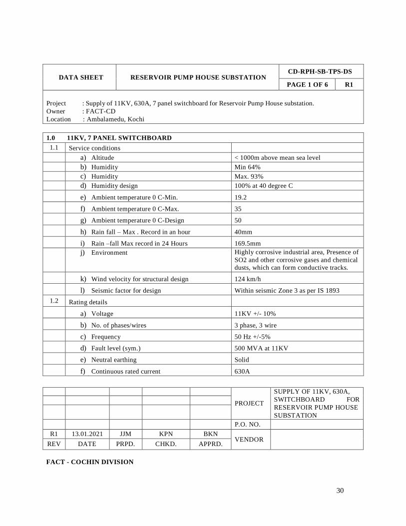
Project : Supply of 11KV, 630A, 7 panel switchboard for Reservoir Pump House substation.
Owner : FACT-CD
Location : Ambalamedu, Kochi
1.0 11KV, 7 PANEL SWITCHBOARD
1.1 Service conditions
a) Altitude < 1000m above mean sea level
b) Humidity Min 64%
c) Humidity Max. 93%
d) Humidity design 100% at 40 degree C
e) Ambient temperature 0 C-Min. 19.2
f) Ambient temperature 0 C-Max. 35
g) Ambient temperature 0 C-Design 50
h) Rain fall – Max . Record in an hour 40mm
i) Rain –fall Max record in 24 Hours 169.5mm
j) Environment Highly corrosive industrial area, Presence of
SO2 and other corrosive gases and chemical
dusts, which can form conductive tracks.
k) Wind velocity for structural design 124 km/h
l) Seismic factor for design Within seismic Zone 3 as per IS 1893
1.2 Rating details
a) Voltage 11KV +/- 10%
b) No. of phases/wires 3 phase, 3 wire
c) Frequency 50 Hz +/-5%
d) Fault level (sym.) 500 MVA at 11KV
e) Neutral earthing Solid
f) Continuous rated current 630A
PROJECT
SUPPLY OF 11KV, 630A,
SWITCHBOARD FOR
RESERVOIR PUMP HOUSE
SUBSTATION
P.O. NO.
R1 13.01.2021 JJM KPN BKN
VENDOR
REV DATE PRPD. CHKD. APPRD.
FACT - COCHIN DIVISION

31
DATA SHEET
RESERVOIR PUMP HOUSE SUBSTATION
CD-RPH-SB-TPS-DS
PAGE 2 OF 6 R1
g) Short time current, KA/sec
Power bus 26.3 KA/1sec
Ground bus 26.3 KA for 3 sec
CT 26.3 KA/1sec
h) Electrically exposed / Non exposed Non exposed
1.3 Control supply
a) DC auxiliary supply voltage (For shunt trip coil,
closing coil, indication lamps, Trip and Non-Trip
alarm annunciation scheme, etc.)
110 V DC
b) AC auxiliary supply voltage for panel anti-
condensation heater, spring charging motor and
DC failure annunciation scheme.
230 V AC
1.4 Panel board
a) Location (Indoor or Outdoor) Indoor Indoor
b) Enclosure IP 4X
c) Bus bars- material(Insulated aluminium/Insulated
copper) Insulated aluminium
d) Earth bus size & material As per IS: 3043, Bare aluminium
e) Mimic diagram Required
f) Cable entry bottom
1.5 Circuit breaker
a) Nominal System Voltage 11 KV
b) Highest System Voltage 12 KV
c) One minute power frequency withstand test
voltage 28 KV (rms)
d) Impulse withstand test voltage 75 KV (peak)
e) Type of breaker SF6/Vacuum
f) No of poles 3
g) Type of movable truck (Floor roll out/cassette
type)
Floor roll out
h) Application Utility distribution network
FACT - COCHIN DIVISION
32
DATA SHEET
RESERVOIR PUMP HOUSE SUBSTATION
CD-RPH-SB-TPS-DS
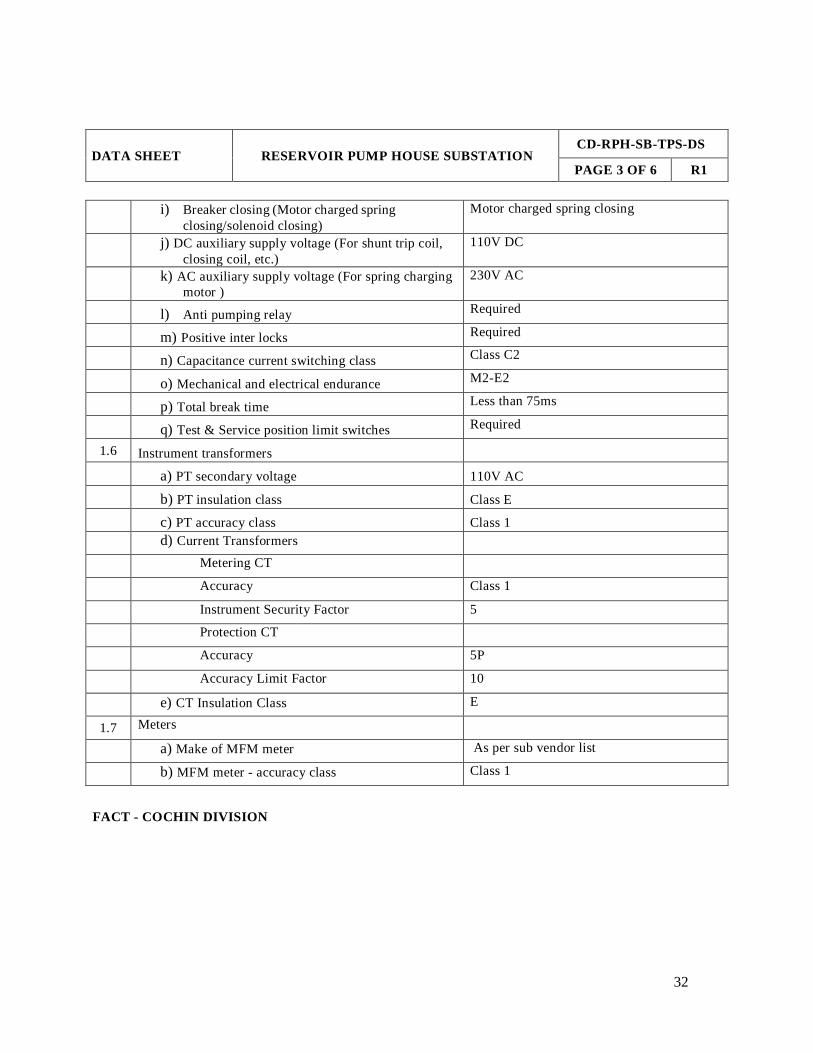
PAGE 3 OF 6 R1
i) Breaker closing (Motor charged spring
closing/solenoid closing)
Motor charged spring closing
j) DC auxiliary supply voltage (For shunt trip coil,
closing coil, etc.)
110V DC
k) AC auxiliary supply voltage (For spring charging
motor )
230V AC
l) Anti pumping relay Required
m) Positive inter locks Required
n) Capacitance current switching class Class C2
o) Mechanical and electrical endurance M2-E2
p) Total break time Less than 75ms
q) Test & Service position limit switches Required
1.6 Instrument transformers
a) PT secondary voltage 110V AC
b) PT insulation class Class E
c) PT accuracy class Class 1
d) Current Transformers
Metering CT
Accuracy Class 1
Instrument Security Factor 5
Protection CT
Accuracy 5P
Accuracy Limit Factor 10
e) CT Insulation Class E
1.7 Meters
a) Make of MFM meter As per sub vendor list
b) MFM meter - accuracy class Class 1
FACT - COCHIN DIVISION

33
DATA SHEET
RESERVOIR PUMP HOUSE SUBSTATION
CD-RPH-SB-TPS-DS
PAGE 4 OF 6 R1
1.8 Push Button
a) No of contacts 1 NO/1NC
b) Current rating 10A
1.9 Protection Relay
a) Make of relay As per sub vendor list
b) Type Flush mounted Numerical relay
c) Application For feeder and transformer protection
d) IDMT characteristic Following IEC curves
e) Relay operation and fault indications Required
1.10 Painting Anticorrosive epoxy based powder coating As
per Engineering Specification
a) Final colour Dark admiralty grey
b) Mimic diagram Required
FACT - COCHIN DIVISION
34
DATA SHEET
RESERVOIR PUMP HOUSE SUBSTATION CD-RPH-SB-TPS-DS
PAGE 5 OF 6 R1
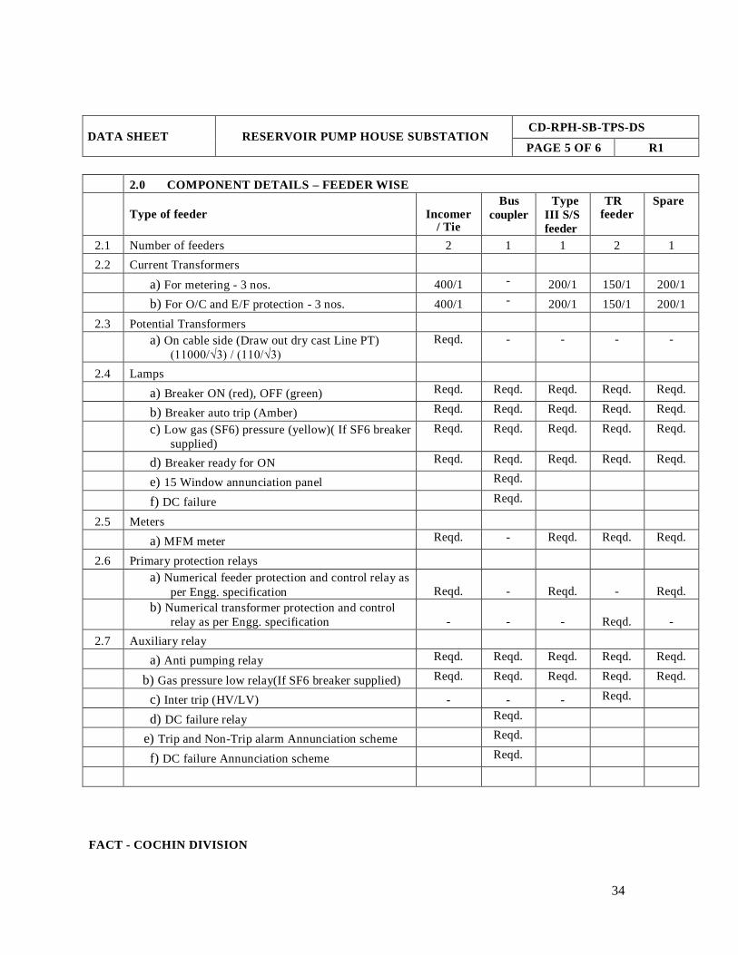
2.0 COMPONENT DETAILS – FEEDER WISE
Type of feeder
Incomer
/ Tie
Bus
coupler
Type
III S/S
feeder
TR feeder
Spare
2.1 Number of feeders 2 1 1 2 1
2.2 Current Transformers
a) For metering - 3 nos. 400/1 - 200/1 150/1 200/1
b) For O/C and E/F protection - 3 nos. 400/1 - 200/1 150/1 200/1
2.3 Potential Transformers
a) On cable side (Draw out dry cast Line PT)
(11000/√3) / (110/√3)
Reqd. - - - -
2.4 Lamps
a) Breaker ON (red), OFF (green) Reqd. Reqd. Reqd. Reqd. Reqd.
b) Breaker auto trip (Amber) Reqd. Reqd. Reqd. Reqd. Reqd.
c) Low gas (SF6) pressure (yellow)( If SF6 breaker
supplied)
Reqd. Reqd. Reqd. Reqd. Reqd.
d) Breaker ready for ON Reqd. Reqd. Reqd. Reqd. Reqd.
e) 15 Window annunciation panel Reqd.
f) DC failure Reqd.
2.5 Meters
a) MFM meter Reqd. - Reqd. Reqd. Reqd.
2.6 Primary protection relays
a) Numerical feeder protection and control relay as
per Engg. specification
Reqd.
-
Reqd.
-
Reqd.
b) Numerical transformer protection and control
relay as per Engg. specification
-
-
-
Reqd.
-
2.7 Auxiliary relay
a) Anti pumping relay Reqd. Reqd. Reqd. Reqd. Reqd.
b) Gas pressure low relay(If SF6 breaker supplied) Reqd. Reqd. Reqd. Reqd. Reqd.
c) Inter trip (HV/LV) - - - Reqd.
d) DC failure relay Reqd.
e) Trip and Non-Trip alarm Annunciation scheme Reqd.
f) DC failure Annunciation scheme Reqd.
FACT - COCHIN DIVISION

35
DATA SHEET
RESERVOIR PUMP HOUSE SUBSTATION CD-RPH-SB-TPS-DS
PAGE 6 OF 6 R1
Type of feeder
Incomer / Tie
Bus
coupler
T/S
feeder
RPH
TR
feeder
Spare
2.8 Control Switches and Push Buttons
a) Breaker Trip-Neutral-Close switch "ODC" Reqd. Reqd. Reqd. Reqd. Reqd.
b) Control switch fuse / MCB for AC aux.
supply
Reqd. Reqd. Reqd. Reqd. Reqd.
c) Control switch fuse / MCB for DC aux.
supply
Reqd. Reqd. Reqd. Reqd. Reqd.
d) Control switch fuse /MCB & Thermostat for
panel anti-condensation heaters
Reqd. Reqd. Reqd. Reqd. Reqd.
e) Control switch fuse/MCB for Spring
Charging Motor
Reqd. Reqd. Reqd. Reqd. Reqd.
f) Accept, Reset and Test Push Buttons for Trip
and Non-Trip alarm Annunciation scheme
Reqd
g) Accept, Reset and Test Push Buttons for DC
failure Annunciation scheme
Reqd.
h) PB for simulate DC failure scheme Reqd.
2.9 Other Items
a) Breaker operation counter Reqd. Reqd. Reqd. Reqd. Reqd.
b) Panel anti-condensation heater (strip type) Reqd. Reqd. Reqd. Reqd. Reqd.
c) Low Voltage compartment panel light and
3 pin socket with switch
Reqd. Reqd. Reqd. Reqd. Reqd.
d) Low gas (SF6) pressure switch and protection
circuit ( If SF6 breaker supplied)
Reqd. Reqd. Reqd. Reqd. Reqd.
e) Test and service position limit switches Reqd. Reqd. Reqd. Reqd. Reqd.
3.0 OTHER REQUIREMENTS
The breakers shall be fully withdrawable truck type. Cassette type breakers are not acceptable.
The cable compartment shall have ample space for termination kits suitable for XLPE cables of sizes specified
in the engineering specification and shall have facilities for support of the cables.
Wiring terminations inside the panels shall be by crimping type lugs only.
The connection to breaker from main busbars shall be rated for breaker/main busbar rating irrespective of CT
rating of outgoing feeders.
Indicating lamps shall be of Clustered LED type
The vendor shall provide all software and hardware required for programming numerical relays.
FACT - COCHIN DIVISION

36
TECHNICAL
PROCUREMENT
SPECIFICATION
VENDOR DATA SUBMISSION PROCEDURE CD-RPH-SB-TPS-VDSP
PAGE 1 OF 3 R1
1.0.0 SCOPE
1.1.0 This document together with “VENDOR DATA REQUIREMENTS (VDR)” defines FACT’s requirements for
vendor drawing and data for any enquiry, work order or purchase order.
1.2.0 Bidders unable to comply with these requirements must detail all exceptions in their proposal. The timely delivery
of quality drawings and data is as crucial as delivery of the equipment itself and hence the same shall be
strictly adhered to after commitment.
1.3.0 Failure to provide adequate preliminary data / drawing may render a proposal non-responsive and hence may
be rejected. After commitment failure to provide documents as per purchase order may delay progressive
payments and adversely affect future invitation to bids.
2.0.0 VENDOR DATA REQUIREMENTS (VDR)
2.1.0 FACT will provide a partially completed VDR form along with each enquiry. This form explains group code
of the document, quantity of each document required and leads time for submission. Columns are available for
the vendor to fill in his deviations, if any, from FACT’s requirements.
2.2.0 The vendor shall forward a filled-in VDR form along with his offer, if he has got any deviation from FACT’s
requirements. In the absence of a filled-in VDR form along with the offer, it will be presumed that the vendor
is accepting FACT’s requirements specified in the VDR.
3.0.0 CLASSIFICATION OF DOUCMENTS
3.1.0 Documents are classified based on their status and nature of content.
3.1.1 Status of documents
1. Preliminary documents required along with the offer.
2. Documents to be submitted after commitment.
3. Final documents.
3.2.0 The documents are further classified into Groups A,B and C, depending on the nature of the documents as
explained below.
3.2.1 Group A requirements
These documents are urgent in nature and contain information that are required for proceeding with the detailed
engineering of surrounding/down stream equipments in the plant and hence are to be submitted on priority basis.
3.2.2 Group B requirements
These documents are to be reviewed by FACT for compliance with the purchase order / work order specifications
but are not essential for other engineering activities of FACT.
3.2.3 Group C requirements
Documents in this group contains data / information / records which are final in nature and that are required for the
equipment user and need not be reviewed by FACT.
FACT - COCHIN DIVISION
37
TECHNICAL
PROCUREMENT
SPECIFICATION
VENDOR DATA SUBMISSION PROCEDURE
CD-RPH-SB-TPS-VDSP
PAGE 2 OF 3 R1
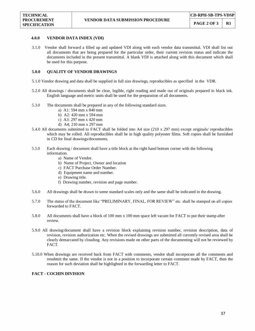
4.0.0 VENDOR DATA INDEX (VDI)
3.1.0 Vendor shall forward a filled up and updated VDI along with each vendor data transmittal. VDI shall list out
all documents that are being prepared for the particular order, their current revision status and indicate the
documents included in the present transmittal. A blank VDI is attached along with this document which shall
be used for this purpose.
5.0.0 QUALITY OF VENDOR DRAWINGS
5.1.0 Vendor drawing and data shall be supplied in full size drawings, reproducibles as specified in the VDR.
5.2.0 All drawings / documents shall be clear, legible, right reading and made out of originals prepared in black ink.
English language and metric units shall be used for the preparation of all documents.
5.3.0 The documents shall be prepared in any of the following standard sizes.
a) A1: 594 mm x 840 mm
b) A2: 420 mm x 594 mm c) A3: 297 mm x 420 mm
d) A4; 210 mm x 297 mm
5.4.0 All documents submitted to FACT shall be folded into A4 size (210 x 297 mm) except originals/ reproducibles
which may be rolled. All reproducibles shall be in high quality polyester films. Soft copies shall be furnished
in CD for final drawings/documents.
5.5.0 Each drawing / document shall have a title block at the right hand bottom corner with the following information.
a) Name of Vendor.
b) Name of Project, Owner and location
c) FACT Purchase Order Number.
d) Equipment name and number. e) Drawing title.
f) Drawing number, revision and page number.
5.6.0 All drawings shall be drawn to some standard scales only and the same shall be indicated in the drawing.
5.7.0 The status of the document like “PRELIMINARY, FINAL, FOR REVIEW” etc. shall be stamped on all copies
forwarded to FACT.
5.8.0 All documents shall have a block of 100 mm x 100 mm space left vacant for FACT to put their stamp after
review.
5.9.0 All drawing/document shall have a revision block explaining revision number, revision description, data of
revision, revision authorization etc. When the revised drawings are submitted all currently revised area shall be
clearly demarcated by clouding. Any revisions made on other parts of the documenting will not be reviewed by
FACT.
5.10.0 When drawings are received back from FACT with comments, vendor shall incorporate all the comments and resubmit the same. If the vendor is not in a position to incorporate certain comment made by FACT, then the
reason for such deviation shall be highlighted in the forwarding letter to FACT.
FACT - COCHIN DIVISION
38
TECHNICAL
PROCUREMENT
SPECIFICATION
VENDOR DATA SUBMISSION PROCEDURE
CD-RPH-SB-TPS-VDSP
PAGE 3 OF 3 R1
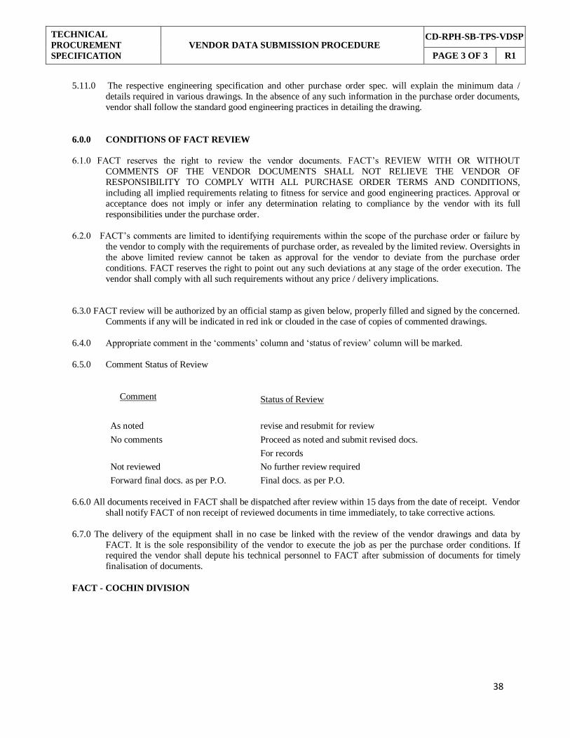
5.11.0 The respective engineering specification and other purchase order spec. will explain the minimum data /
details required in various drawings. In the absence of any such information in the purchase order documents,
vendor shall follow the standard good engineering practices in detailing the drawing.
6.0.0 CONDITIONS OF FACT REVIEW
6.1.0 FACT reserves the right to review the vendor documents. FACT’s REVIEW WITH OR WITHOUT
COMMENTS OF THE VENDOR DOCUMENTS SHALL NOT RELIEVE THE VENDOR OF
RESPONSIBILITY TO COMPLY WITH ALL PURCHASE ORDER TERMS AND CONDITIONS,
including all implied requirements relating to fitness for service and good engineering practices. Approval or
acceptance does not imply or infer any determination relating to compliance by the vendor with its full
responsibilities under the purchase order.
6.2.0 FACT’s comments are limited to identifying requirements within the scope of the purchase order or failure by
the vendor to comply with the requirements of purchase order, as revealed by the limited review. Oversights in
the above limited review cannot be taken as approval for the vendor to deviate from the purchase order
conditions. FACT reserves the right to point out any such deviations at any stage of the order execution. The
vendor shall comply with all such requirements without any price / delivery implications.
6.3.0 FACT review will be authorized by an official stamp as given below, properly filled and signed by the concerned.
Comments if any will be indicated in red ink or clouded in the case of copies of commented drawings.
6.4.0 Appropriate comment in the ‘comments’ column and ‘status of review’ column will be marked.
6.5.0 Comment Status of Review
Comment Status of Review
As noted revise and resubmit for review
No comments Proceed as noted and submit revised docs.
For records
Not reviewed No further review required
Forward final docs. as per P.O. Final docs. as per P.O.
6.6.0 All documents received in FACT shall be dispatched after review within 15 days from the date of receipt. Vendor
shall notify FACT of non receipt of reviewed documents in time immediately, to take corrective actions.
6.7.0 The delivery of the equipment shall in no case be linked with the review of the vendor drawings and data by
FACT. It is the sole responsibility of the vendor to execute the job as per the purchase order conditions. If required the vendor shall depute his technical personnel to FACT after submission of documents for timely
finalisation of documents.
FACT - COCHIN DIVISION

TECHNICAL
PROCUREMENT
SPECIFICATION
VENDOR DATA REQUIREMENTS CD-RPH-SB-TPS-VDR
PAGE 1 OF 2 R1
PROJECT: SUPPLY OF 11KV, 630A, 7 PANEL
SWITCHBOARD FOR RESERVOIR PUMP ITEM: 11KV, 7 PANEL SWITCHBOARD
HOUSE SUBSTATION
TPS. NO: CD-RPH-SB-TPS
STATUS: ENQUIRY COMMITMENT P.O. NO.:
Sl.
No.
Grp.
code
Description
Offer After commitment @@
Final
Qty.
Qty.
Lead time in weeks
Qty.
Reqd @ Propd Agrd
1.0
B Duly filled in Technical particulars of 11 KV,7
PANEL SWITCHBOARD as per Pro forma enclosed
1S
2P
4
4P
2.0 A Dimensioned general arrangement drawings – internal & external, including busbar disposition 1S 2P 4
4P
3.0
A
Sectional views showing the general constructional
features of the circuit breaker including operating
mechanism, arcing chambers, contacts with lifting dimensions for maintenance.
1S
2P
4
4P
4.0
A Foundation plan showing cut-outs / floor openings and foundation pockets. Loading data and foundation design
1S
2P
4
4P
5.0 A
Bill of material for complete switchgear
1S 2P 4
4P
6.0
B
Single line diagram, control schematic, wiring
diagrams, inters panel wiring, terminal and bus wiring diagrams.
1S
2P
4
4P
7.0 B Schedule of materials / components.
1S 2P 4
4P
8.0 B Characteristic curves of relays and their range of
adjustments.
2P 4
2P
9.0 B Type test certificates of breakers.
1S
4
2P
10.0 C Routine test certificates.
2P 4
2P
Legend: @ Group code: A-For review and detailed Engineering, B-For review, C- For information and record
@@ Document type: S-Soft Copy, P-Print.
Notes: Vendor shall fill in proposed lead-time if different from the required lead-time.
Each set of final documents shall be submitted in a folder. Two such folders shall be packed and despatched with the equipment.
R1 13.01.2021 REV 1 JJM KPN BKN
REV
NO.
DATE
DESCRIPTION
PREPARED
CHECKED
APPROVED
FACT - COCHIN DIVISION
39

TECHNICAL
PROCUREMENT
SPECIFICATION
VENDOR DATA REQUIREMENTS CD-RPH-SB-TPS-VDR
PAGE 2 OF 2 R1
PROJECT: SUPPLY OF 11KV, 630A, 7 PANEL
SWITCHBOARD FOR RESERVOIR PUMP ITEM: 11KV, 7 PANEL SWITCHBOARD
HOUSE SUBSTATION
TPS. NO: CD-RPH-SB-TPS
STATUS: ENQUIRY COMMITMENT P.O. NO.:
Sl.
No.
Grp.
code
Description
Offer After commitment @@
Final
Qty.
Qty.
Lead time in weeks
Qty.
Reqd @ Propd Agrd
11.0 B Certificate of short circuit rating of breakers.
1S
4
2P
12.0
B
Test certificates of bought out items like protective
relays, Circuit Breakers, PTs, CTs, energy meters etc.
2P
4
2P
13.0 B Technical literatures, pamphlets and brochures
relating to the various equipments used. 1S 1S
2P+
1S
14.0 C Operation and Maintenance manuals. 3P+
1S
3P+
1S
15.0 B Spare parts list
1S
2P
16.0 B Duly filled and signed Compliance Statement as per pro forma enclosed.
1S
-
2P
17.0 B Duly filled and signed Vendor’s Experience
statement as per pro forma enclosed.
18.0 B Un-priced copy of price data sheet
1S
-
2P
19.0 B Relay coordination details, with recommended
settings, calculations etc.
2P 1P
2P
20.0 B Dimensioned drawings of bus trunking flange
showing bus bar arrangement, bolt hole etc.
2P 4
2P
Legend: @ Group code: A-For review and detailed Engineering, B-For review, C- For information and record
@@ Document type: S-Soft Copy, P-Print.
Notes:
Vendor shall fill in proposed lead-time if different from the required lead-time.
Each set of final documents shall be submitted in a folder. Two such folders shall be packed and
despatched with the equipment.
R1 13.01.2021 REV 1 JJM KPN BKN
REV NO.
DATE
DESCRIPTION
PREPARED
CHECKED
APPROVED
FACT - COCHIN DIVISION
40

TECHNICAL
PROCUREMENT SPECIFICATION
VENDOR DATA INDEX
CD-RPH-SB-TPS-VDI
PAGE 1 OF 1 R1
PROJECT: Supply of 11KV, 630A, 7 panel switchboard
for Reservoir Pump House substation.
TPS NO: CD-RPH-SB-TPS
VENDOR:
ITEM: 11KV, 7 PANEL SWITCHBOARD P.O NO.: DATE:
Sl.
No.
Doc. / Drawing No.
Description
Rev. 0
Date
Rev. 1
Date
Rev. 2
Date
Rev. 3
Date
Rev. 4
Date
Rev. 5
Date
Relevant
to This
issue
ISSUE No.
DATE
SIGNATURE
FACT - COCHIN DIVISION
41

TECHNICAL
PROCUREMENT SPECIFICATION
TECHNICAL CHECK LIST – FORMAT CD-RPH-SB-TPS-TCL
PAGE 1 OF 12 R1
Sl.
No.
FACT’s Requirements
Quantity Bidder’s
Confirmation
(Strike off
whichever is not
applicable)
Details/ Remarks/
Deviation if any
Required
Offered
1.0 11 KV, 630 Amps, 26.3 KA, indoor, 7 panel switchboard with SF6/Vacuum
circuit breaker as per following details 1 No.
Complied/
Not Complied
1.1 7 panel switchboards meet all standards specified in the engineering specification (Tag No. CD-RPH-SB-TPS-ES)
Complied/ Not Complied
1.2 Internal arc test for panel board at designed fault current - required Complied/
Not Complied
1.3 Degree of protection - not less than IP 4X Complied/
Not Complied
1.4 Seal-off bushings, arc propagation barriers , Explosion vents - required Complied/
Not Complied
1.5 Minimum size of sheet steel - 2mm Complied/
Not Complied
1.6 Panel board minimum width - 600mm. Entire panel width is < /= 5 meter Complied/
Not Complied
1.7 Removable gland plates required in rear bottom plate of cable compartment.
Minimum 600 mm clear height required for cable termination.
Complied/
Not Complied
1.8 Switchgear shall be suitable for bottom entry of the cable. Complied/ Not Complied
1.9 Relays are placed at reasonable operating height from the floor level. Maximum operating height shall be 1900 mm and minimum 500 mm from the floor level
Complied/ Not Complied
1.10 CB truck can be moved and change position without opening the cubicle door Complied/
Not Complied
FACT - COCHIN DIVISION 42

43
TECHNICAL
PROCUREMENT
SPECIFICATION
TECHNICAL CHECK LIST – FORMAT
CD-RPH-SB-TPS-TCL
PAGE 2 OF 12 R1
Sl.
No.
FACT’s Requirements
Quantity Bidder’s
Confirmation
(Strike off
whichever is not
applicable)
Details/ Remarks/
Deviation if any Required Offered
1.11 Type of breaker- SF6/Vacuum circuit breaker, three pole, horizontal draw out,
horizontal isolation and floor rollout type
Complied/
Not Complied
1.12 The breakers shall be E2, M2 and C2 class type tested. Complied/
Not Complied
1.13 Rated operating duty shall normally be O-0.3s-CO-3min-CO Complied/
Not Complied
1.14 Total break time: Less than 75ms Complied/
Not Complied
1.15 Breakers of same ratings shall be interchangeable. Wiring and termination of
plug-in contacts shall be identical in all interchangeable breakers.
Complied/
Not Complied
1.16 Breaker isolating contacts shall be self-aligning type Complied/
Not Complied
1.17 A minimum of 4 sets of auxiliary contacts shall be provided on breaker operating
mechanism as spare. Auxiliary contacts continuous rating - 10A at 240V
Complied/
Not Complied
1.18 The breaker operating mechanism - quick make, quick break type and trip-free as
per relevant code of protection
Complied/ Not Complied
1.19
Electrically operated motor charged spring closing mechanism shall be used in the
breaker with provision for manual charging through handle. Necessary operating
handles offered.
Complied/
Not Complied
1.20 The closing solenoids / coils and auxiliary devices - operate satisfactorily between
85 and 110% of the rated auxiliary supply voltage indicated in the data sheet
Complied/
Not Complied
1.21 Trip coils operate satisfactorily at all voltages between 70% and 110% of the
rated auxiliary voltage
Complied/
Not Complied
FACT - COCHIN DIVISION
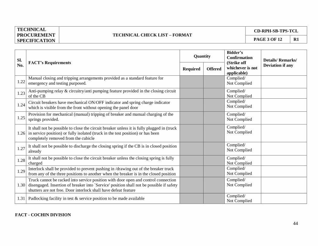
FACT - COCHIN DIVISION
44
TECHNICAL
PROCUREMENT
SPECIFICATION
TECHNICAL CHECK LIST – FORMAT
CD-RPH-SB-TPS-TCL
PAGE 3 OF 12 R1
Sl.
No.
FACT’s Requirements
Quantity Bidder’s
Confirmation
(Strike off
whichever is not
applicable)
Details/ Remarks/
Deviation if any Required Offered
1.22 Manual closing and tripping arrangements provided as a standard feature for
emergency and testing purposed.
Complied/
Not Complied
1.23 Anti-pumping relay & circuitry/anti pumping feature provided in the closing circuit
of the CB
Complied/
Not Complied
1.24 Circuit breakers have mechanical ON/OFF indicator and spring charge indicator
which is visible from the front without opening the panel door
Complied/ Not Complied
1.25 Provision for mechanical (manual) tripping of breaker and manual charging of the
springs provided.
Complied/
Not Complied
1.26
It shall not be possible to close the circuit breaker unless it is fully plugged in (truck in service position) or fully isolated (truck in the test position) or has been
completely removed from the cubicle
Complied/ Not Complied
1.27 It shall not be possible to discharge the closing spring if the CB is in closed position
already
Complied/
Not Complied
1.28 It shall not be possible to close the circuit breaker unless the closing spring is fully charged
Complied/ Not Complied
1.29 Interlock shall be provided to prevent pushing in /drawing out of the breaker truck
from any of the three positions to another when the breaker is in the closed position
Complied/
Not Complied
1.30
Truck cannot be racked into service position with door open and control connection
disengaged. Insertion of breaker into `Service' position shall not be possible if safety
shutters are not free. Door interlock shall have defeat feature
Complied/
Not Complied
1.31 Padlocking facility in test & service position to be made available Complied/
Not Complied
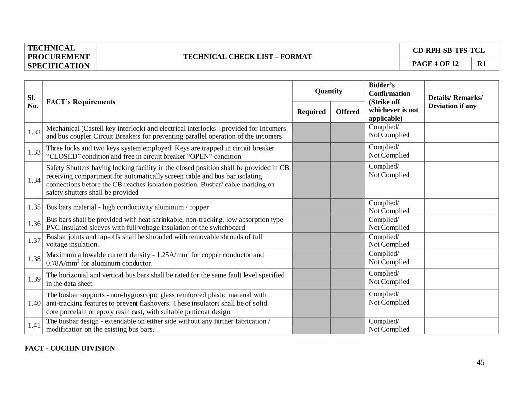
FACT - COCHIN DIVISION
45
TECHNICAL
PROCUREMENT
SPECIFICATION
TECHNICAL CHECK LIST – FORMAT
CD-RPH-SB-TPS-TCL
PAGE 4 OF 12 R1
Sl.
No.
FACT’s Requirements
Quantity Bidder’s
Confirmation
(Strike off
whichever is not
applicable)
Details/ Remarks/
Deviation if any Required Offered
1.32 Mechanical (Castell key interlock) and electrical interlocks - provided for Incomers and bus coupler Circuit Breakers for preventing parallel operation of the incomers
Complied/
Not Complied
1.33 Three locks and two keys system employed. Keys are trapped in circuit breaker “CLOSED” condition and free in circuit breaker “OPEN” condition
Complied/ Not Complied
1.34
Safety Shutters having locking facility in the closed position shall be provided in CB
receiving compartment for automatically screen cable and bus bar isolating
connections before the CB reaches isolation position. Busbar/ cable marking on safety shutters shall be provided
Complied/
Not Complied
1.35 Bus bars material - high conductivity aluminum / copper Complied/
Not Complied
1.36 Bus bars shall be provided with heat shrinkable, non-tracking, low absorption type PVC insulated sleeves with full voltage insulation of the switchboard
Complied/ Not Complied
1.37 Busbar joints and tap-offs shall be shrouded with removable shrouds of full voltage insulation.
Complied/ Not Complied
1.38 Maximum allowable current density - 1.25A/mm2 for copper conductor and
0.78A/mm2 for aluminum conductor.
Complied/
Not Complied
1.39 The horizontal and vertical bus bars shall be rated for the same fault level specified
in the data sheet
Complied/ Not Complied
1.40
The busbar supports - non-hygroscopic glass reinforced plastic material with
anti-tracking features to prevent flashovers. These insulators shall be of solid
core porcelain or epoxy resin cast, with suitable petticoat design
Complied/
Not Complied
1.41 The busbar design - extendable on either side without any further fabrication / modification on the existing bus bars.
Complied/ Not Complied

FACT - COCHIN DIVISION
46
TECHNICAL
PROCUREMENT
SPECIFICATION
TECHNICAL CHECK LIST – FORMAT
CD-RPH-SB-TPS-TCL
PAGE 5 OF 12 R1
Sl.
No.
FACT’s Requirements
Quantity Bidder’s
Confirmation
(Strike off
whichever is not
applicable)
Details/ Remarks/
Deviation if any Required Offered
1.42 CTs shall withstand the maximum short circuit current for a minimum of one
second and it shall be designed to withstand stresses resulting from the maximum short circuit currents.
Complied/
Not Complied
1.43 Low reactance CTs shall be used for protection Complied/
Not Complied
1.44 CTs for metering shall have adequate capacity to cater for 130% of full load conditions.
Complied/ Not Complied
1.45 Metering CT Accuracy - Class 1, Instrument Security Factor - 5 Complied/
Not Complied
1.46 Protection CT Accuracy - 5P, Accuracy Limit Factor - 10 Complied/
Not Complied
1.47 CT Insulation Class - E Complied/
Not Complied
1.48
The actual burden of the CTs shall meet the requirements of relays, instruments and
leads associated with the particular CT including 20% spare capacity
Complied/
Not Complied
1.49
Separate CTs / cores used for metering and protection. Dual purposes CTs shall not be used.
Complied/ Not Complied
1.50 CTs provided with polarity markings adjacent to terminals, both for primary and
secondary
Complied/ Not Complied
1.51 CTs shall have solidly earthed system Complied/
Not Complied

FACT - COCHIN DIVISION
47
TECHNICAL
PROCUREMENT
SPECIFICATION
TECHNICAL CHECK LIST – FORMAT
CD-RPH-SB-TPS-TCL
PAGE 6 OF 12 R1
Sl.
No.
FACT’s Requirements
Quantity Bidder’s
Confirmation
(Strike off
whichever is not
applicable)
Details/ Remarks/
Deviation if any Required Offered
1.52 PTs shall have suitable accuracy and capacity for the satisfactory operation of the
instrumentation and metering specified in the data sheet / drawings enclosed
Complied/
Not Complied
1.53 Potential transformer shall be ‘fully drew out’ type with HRC fuses on both HV and LV sides
Complied/ Not Complied
1.54 Potential transformer – draw out type Complied/
Not Complied
1.55 PT secondary voltage - 110V AC Complied/
Not Complied
1.56 PT accuracy class - Class 1 Complied/
Not Complied
1.57 PT insulation class - Class E Complied/
Not Complied
1.58 PTs shall have solidly earthed system Complied/
Not Complied
1.59 PT selection scheme - required Complied/
Not Complied
1.60 Protection relay shall have control, measurement and supervision facility. Complied/
Not Complied
1.61
Protection relay type - back connected, draw out / plug-in type, flush mounted and
fitted with dust tight covers.
Complied/ Not Complied
1.62 Protection relay shall be compatible with protection CT secondary current of 1A or 5A.
Complied/ Not Complied

48
TECHNICAL
PROCUREMENT
SPECIFICATION
TECHNICAL CHECK LIST – FORMAT
CD-RPH-SB-TPS-TCL
PAGE 7 OF 12 R1
Sl.
No.
FACT’s Requirements
Quantity Bidder’s
Confirmation
(Strike off
whichever is not
applicable)
Details/ Remarks/
Deviation if any Required Offered
1.63 Protection relay shall be suitable for auxiliary (control) power supply of 110V
DC with 70-110% variation
Complied/
Not Complied
1.64 Protection relays voltage input (PT input) - 110 volt A.C. supply, obtained from
PT selection scheme
Complied/
Not Complied
1.65 Protection relay - conformed to the latest edition of IS: 3231/IEC 60255. Complied/
Not Complied
1.66 Protection relays IDMT characteristic - complying with IEC curves. Complied/
Not Complied
1.67 Protection relays have healthy/relay in operation indication on fascia Complied/
Not Complied
1.68 Protection relays shall have minimum of 8 numbers of programmable binary inputs
and programmable binary outputs.
Complied/
Not Complied
1.69 Protection relay shall be compatible for solidly grounded networks Complied/
Not Complied
1.70
Protection relay shall support both the parallel redundancy protocol (PRP) and the
high-availability seamless redundancy (HSR) protocol together with the DNP3,
IEC 60870-5-103, Ethernet IEC-61850 and Modbus protocols
Complied/
Not Complied
1.71 Protection relay shall have RS 485 serial communication port and RJ 45 Ethernet communication port.
Complied/ Not Complied
1.72
Protection relay shall have LCD/LED display unit, keypads, LED indicators and
communication port for parameter setting, monitoring and controlling the
protection relay
Complied/
Not Complied
FACT - COCHIN DIVISION
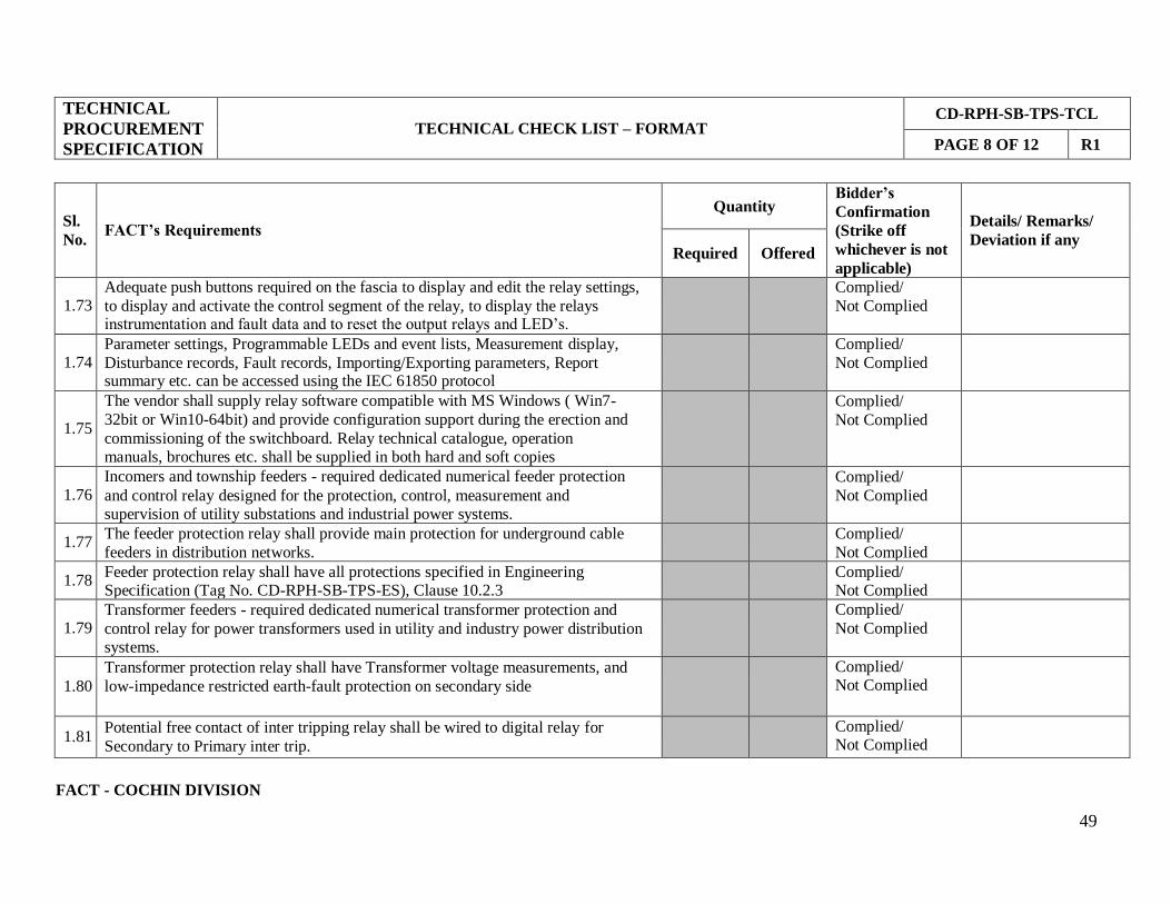
49
TECHNICAL
PROCUREMENT
SPECIFICATION
TECHNICAL CHECK LIST – FORMAT
CD-RPH-SB-TPS-TCL
PAGE 8 OF 12 R1
Sl.
No.
FACT’s Requirements
Quantity Bidder’s
Confirmation
(Strike off
whichever is not
applicable)
Details/ Remarks/
Deviation if any Required Offered
1.73 Adequate push buttons required on the fascia to display and edit the relay settings,
to display and activate the control segment of the relay, to display the relays instrumentation and fault data and to reset the output relays and LED’s.
Complied/
Not Complied
1.74 Parameter settings, Programmable LEDs and event lists, Measurement display,
Disturbance records, Fault records, Importing/Exporting parameters, Report summary etc. can be accessed using the IEC 61850 protocol
Complied/
Not Complied
1.75
The vendor shall supply relay software compatible with MS Windows ( Win7-
32bit or Win10-64bit) and provide configuration support during the erection and
commissioning of the switchboard. Relay technical catalogue, operation manuals, brochures etc. shall be supplied in both hard and soft copies
Complied/
Not Complied
1.76 Incomers and township feeders - required dedicated numerical feeder protection
and control relay designed for the protection, control, measurement and supervision of utility substations and industrial power systems.
Complied/
Not Complied
1.77 The feeder protection relay shall provide main protection for underground cable
feeders in distribution networks.
Complied/
Not Complied
1.78 Feeder protection relay shall have all protections specified in Engineering Specification (Tag No. CD-RPH-SB-TPS-ES), Clause 10.2.3
Complied/ Not Complied
1.79 Transformer feeders - required dedicated numerical transformer protection and
control relay for power transformers used in utility and industry power distribution systems.
Complied/
Not Complied
1.80
Transformer protection relay shall have Transformer voltage measurements, and
low-impedance restricted earth-fault protection on secondary side
Complied/ Not Complied
1.81 Potential free contact of inter tripping relay shall be wired to digital relay for
Secondary to Primary inter trip.
Complied/ Not Complied
FACT - COCHIN DIVISION
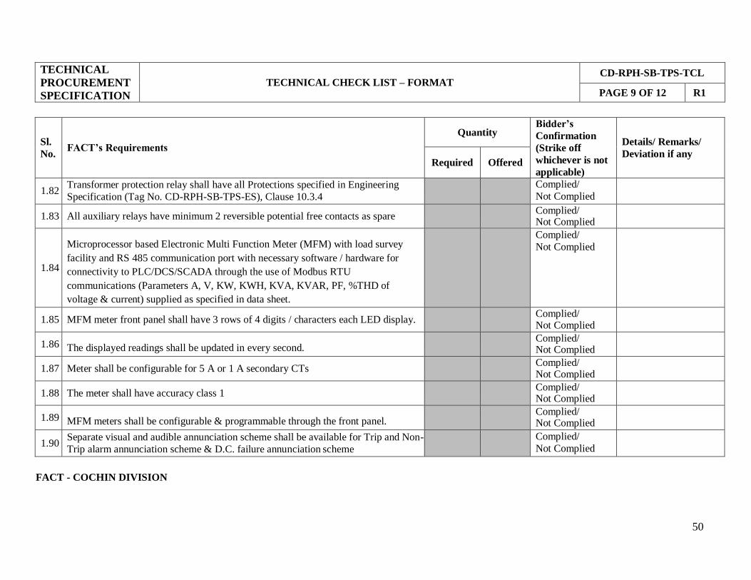
50
TECHNICAL
PROCUREMENT
SPECIFICATION
TECHNICAL CHECK LIST – FORMAT
CD-RPH-SB-TPS-TCL
PAGE 9 OF 12 R1
Sl.
No.
FACT’s Requirements
Quantity Bidder’s
Confirmation
(Strike off
whichever is not
applicable)
Details/ Remarks/
Deviation if any Required Offered
1.82 Transformer protection relay shall have all Protections specified in Engineering
Specification (Tag No. CD-RPH-SB-TPS-ES), Clause 10.3.4
Complied/
Not Complied
1.83 All auxiliary relays have minimum 2 reversible potential free contacts as spare Complied/
Not Complied
1.84
Microprocessor based Electronic Multi Function Meter (MFM) with load survey
facility and RS 485 communication port with necessary software / hardware for
connectivity to PLC/DCS/SCADA through the use of Modbus RTU
communications (Parameters A, V, KW, KWH, KVA, KVAR, PF, %THD of
voltage & current) supplied as specified in data sheet.
Complied/
Not Complied
1.85 MFM meter front panel shall have 3 rows of 4 digits / characters each LED display. Complied/
Not Complied
1.86
The displayed readings shall be updated in every second. Complied/
Not Complied
1.87 Meter shall be configurable for 5 A or 1 A secondary CTs Complied/
Not Complied
1.88 The meter shall have accuracy class 1 Complied/
Not Complied
1.89
MFM meters shall be configurable & programmable through the front panel. Complied/
Not Complied
1.90 Separate visual and audible annunciation scheme shall be available for Trip and Non-
Trip alarm annunciation scheme & D.C. failure annunciation scheme
Complied/
Not Complied
FACT - COCHIN DIVISION

51
TECHNICAL
PROCUREMENT
SPECIFICATION
TECHNICAL CHECK LIST – FORMAT
CD-RPH-SB-TPS-TCL
PAGE 10 OF 12 R1
Sl.
No.
FACT’s Requirements
Quantity Bidder’s
Confirmation
(Strike off
whichever is not
applicable)
Details/ Remarks/
Deviation if any Required Offered
1.91 It shall be possible to check the healthiness of fascia windows and DC failure
indication lamp by pressing the respective lamp test PB
Complied/
Not Complied
1.92 All protection relays trip and alarm contacts shall be wired to the Trip and Non- Trip alarm annunciation scheme
Complied/ Not Complied
1.93 A 15 window annunciation panel shall be provided on the bus coupler panel Complied/
Not Complied
1.94 The Trip and Non-Trip alarm annunciation scheme shall be rated for 110 V D.C. auxiliary supply
Complied/ Not Complied
1.95
The annunciation scheme shall be repetitive and shall be ready to receive and
initiate systematically a second or third fault, irrespective of whether the alarm due
to first or second fault in other panels is in ’initiated’ or ’accepted’ or ‘relay reset’ condition prior to fully resetting of the annunciation scheme.
Complied/
Not Complied
1.96 Instantaneously operated DC under voltage relay provided in bus coupler panel Complied/
Not Complied
1.97
The D.C. failure annunciation scheme shall be rated for 110 V A.C. auxiliary
supply obtained from PT selection scheme.
Complied/
Not Complied
1.98
All push buttons have minimum 1 NO / 1 NC contacts and rated for 10A Complied/
Not Complied
1.99 Indicating lamps shall be of cluster LED type with 7 watts maximum rating Complied/
Not Complied
FACT - COCHIN DIVISION
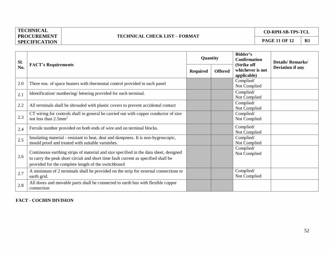
52
TECHNICAL
PROCUREMENT
SPECIFICATION
TECHNICAL CHECK LIST – FORMAT
CD-RPH-SB-TPS-TCL
PAGE 11 OF 12 R1
Sl.
No.
FACT’s Requirements
Quantity Bidder’s
Confirmation
(Strike off
whichever is not
applicable)
Details/ Remarks/
Deviation if any Required Offered
2.0 Three nos. of space heaters with thermostat control provided in each panel Complied/
Not Complied
2.1 Identification/ numbering/ lettering provided for each terminal. Complied/ Not Complied
2.2 All terminals shall be shrouded with plastic covers to prevent accidental contact Complied/
Not Complied
2.3 CT wiring for controls shall in general be carried out with copper conductor of size not less than 2.5mm2
Complied/ Not Complied
2.4 Ferrule number provided on both ends of wire and on terminal blocks. Complied/
Not Complied
2.5 Insulating material - resistant to heat, dust and dampness. It is non-hygroscopic, mould proof and treated with suitable varnishes.
Complied/ Not Complied
2.6 Continuous earthing strips of material and size specified in the data sheet, designed
to carry the peak short circuit and short time fault current as specified shall be
provided for the complete length of the switchboard
Complied/
Not Complied
2.7 A minimum of 2 terminals shall be provided on the strip for external connections to
earth grid.
Complied/
Not Complied
2.8 All doors and movable parts shall be connected to earth bus with flexible copper
connection
FACT - COCHIN DIVISION

TECHNICAL
PROCUREMENT
SPECIFICATION
TECHNICAL CHECK LIST – FORMAT
CD-RPH-SB-TPS-TCL
PAGE 12 OF 12 R1
Sl.
No.
FACT’s Requirements
Quantity Bidder’s
Confirmation
(Strike off
whichever is not
applicable)
Details/ Remarks/
Deviation if any Required Offered
2.9 All non-current carrying metal work (including metallic cases of instruments and
other panel mounted components) of the equipment shall be earthed.
Complied/
Not Complied
2.10
All metal parts of the panel to undergo surface treatment that includes derusting,
cleaning chemically, degreasing, pickling in acid, cold rinsing, phosphating and
passivating followed by spraying with two coats of zinc oxide primer and baking in oven
Complied/
Not Complied
2.11
The sheet steel housing and all the metal surfaces shall be properly cleaned and
coated with two coats of anticorrosive paint over two coats of suitable primer. A final coat in gloss finish with a colour indicated shall also be given to the
switchboard.
Complied/
Not Complied
2.12 Painted mimic diagram provided on all the panels of the switchboard Complied/ Not Complied
2.13 Necessary foundation channels (if not integral), bolts and nuts shall be supplied
along with the equipment.
Complied/
Not Complied
2.14 Flexible test cord 2m long with plug and socket for testing the breakers in the
withdrawn position shall be supplied in a separate case
Complied/
Not Complied
2.15 Alternatively flexible cord used for test position shall have sufficient extra length
to test the breaker in the withdrawn position also
Complied/
Not Complied
2.16 Earthing and testing plugs for cables and busbars shall be supplied in a separate
box.
Complied/
Not Complied
2.17
Spare parts and special tools recommended for keeping stock for trouble free
operation of CB panel for a minimum period of 2 years shall be supplied. List and
catalogue numbers of these spare parts shall also be furnished.
Complied/
Not Complied
FACT - COCHIN DIVISION 53

54
TECHNICAL
PROCUREMENT
SPECIFICATION
PRICE FORMAT CD-RPH-SB-TPS-PF
PAGE 1 OF 1 R1
TPS NO: CD-RPH-SB-TPS
ITEM: 11KV, 7 PANEL SWITCHBOARD
Sl. No.
Description Quantity Unit price
Tax Total price
X
1.0
Design, engineering, manufacturing, testing at works
and supply of 11 kV, 630 A, 26.3 kA SF6/Vacuum
circuit breaker, 7 panel switchboard for Reservoir
Pump House substation, conforming to attached
specifications/documents.
1 Set
2.0 Supply of spares as per spare list 1 Set
R1 18.09.2018 REV 1 JERRY PARAMESWARN BINNY
REV
NO. DATE DESCRIPTION PREPARED CHECKED APPROVED
FACT - COCHIN DIVISION
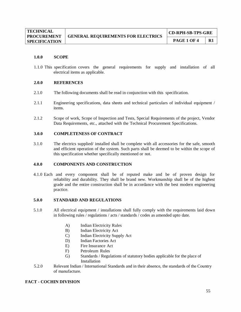
55
TECHNICAL
PROCUREMENT
SPECIFICATION
GENERAL REQUIREMENTS FOR ELECTRICS CD-RPH-SB-TPS-GRE
PAGE 1 OF 4 R1
1.0.0 SCOPE
1.1.0 This specification covers the general requirements for supply and installation of all
electrical items as applicable.
2.0.0 REFERENCES
2.1.0 The following documents shall be read in conjunction with this specification.
2.1.1 Engineering specifications, data sheets and technical particulars of individual equipment /
items.
2.1.2 Scope of work, Scope of Inspection and Tests, Special Requirements of the project, Vendor
Data Requirements, etc., attached with the Technical Procurement Specifications.
3.0.0 COMPLETENESS OF CONTRACT
3.1.0 The electrics supplied/ installed shall be complete with all accessories for the safe, smooth
and efficient operation of the system. Such parts shall be deemed to be within the scope of
this specification whether specifically mentioned or not.
4.0.0 COMPONENTS AND CONSTRUCTION
4.1.0 Each and every component shall be of reputed make and be of proven design for
reliability and durability. They shall be brand new. Workmanship shall be of the highest
grade and the entire construction shall be in accordance with the best modern engineering
practice.
5.0.0 STANDARD AND REGULATIONS
5.1.0 All electrical equipment / installations shall fully comply with the requirements laid down
in following rules / regulations / acts / standards / codes as amended upto date.
A) Indian Electricity Rules
B) Indian Electricity Act
C) Indian Electricity Supply Act
D) Indian Factories Act
E) Fire Insurance Act
F) Petroleum Rules
G) Standards / Regulations of statutory bodies applicable for the place of
Installation
5.2.0 Relevant Indian / International Standards and in their absence, the standards of the Country
of manufacture.
FACT - COCHIN DIVISION
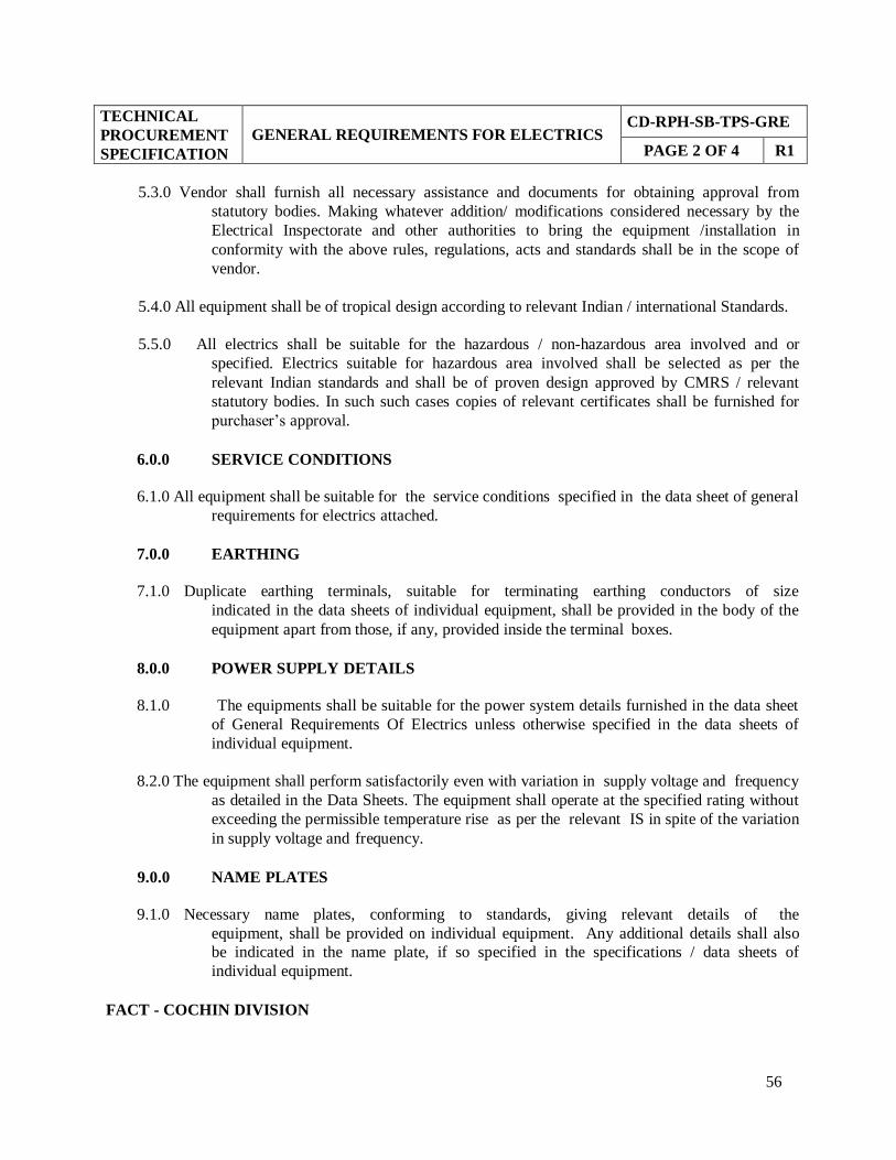
56
TECHNICAL
PROCUREMENT
SPECIFICATION
GENERAL REQUIREMENTS FOR ELECTRICS CD-RPH-SB-TPS-GRE
PAGE 2 OF 4 R1
5.3.0 Vendor shall furnish all necessary assistance and documents for obtaining approval from
statutory bodies. Making whatever addition/ modifications considered necessary by the
Electrical Inspectorate and other authorities to bring the equipment /installation in
conformity with the above rules, regulations, acts and standards shall be in the scope of
vendor.
5.4.0 All equipment shall be of tropical design according to relevant Indian / international Standards.
5.5.0 All electrics shall be suitable for the hazardous / non-hazardous area involved and or
specified. Electrics suitable for hazardous area involved shall be selected as per the
relevant Indian standards and shall be of proven design approved by CMRS / relevant
statutory bodies. In such such cases copies of relevant certificates shall be furnished for
purchaser’s approval.
6.0.0 SERVICE CONDITIONS
6.1.0 All equipment shall be suitable for the service conditions specified in the data sheet of general
requirements for electrics attached.
7.0.0 EARTHING
7.1.0 Duplicate earthing terminals, suitable for terminating earthing conductors of size
indicated in the data sheets of individual equipment, shall be provided in the body of the
equipment apart from those, if any, provided inside the terminal boxes.
8.0.0 POWER SUPPLY DETAILS
8.1.0 The equipments shall be suitable for the power system details furnished in the data sheet
of General Requirements Of Electrics unless otherwise specified in the data sheets of
individual equipment.
8.2.0 The equipment shall perform satisfactorily even with variation in supply voltage and frequency
as detailed in the Data Sheets. The equipment shall operate at the specified rating without
exceeding the permissible temperature rise as per the relevant IS in spite of the variation
in supply voltage and frequency.
9.0.0 NAME PLATES
9.1.0 Necessary name plates, conforming to standards, giving relevant details of the
equipment, shall be provided on individual equipment. Any additional details shall also
be indicated in the name plate, if so specified in the specifications / data sheets of
individual equipment.
FACT - COCHIN DIVISION

57
TECHNICAL
PROCUREMENT
SPECIFICATION
GENERAL REQUIREMENTS FOR ELECTRICS CD-RPH-SB-TPS-GRE
PAGE 3 OF 4 R1
10.0.0 PAINTING
10.1.0 Unless otherwise specified in the specifications / data sheets of individual equipment
/items, painting procedure described in this clause shall be adopted.
10.2.0 All exposed metal parts shall be subjected to at least the following pre-treatment before
painting to suit the material and environment involved.
a) De-greasing
b) Rust removing
c) Phosphating / equivalent chemical treatment.
10.3.0 Giving two coats of anti-corrosive painting shall be given after the above process so as
to render the material suitable for the highly corrosive environment specified.
10.4.0 Final colour and finish of the equipment shall be dark admiralty grey as per IS: 5 unless
specified elsewhere.
10.5.0 Vendor shall furnish detailed painting procedure proposed, along with the bid.
11.0.0 INTER-CHANGEABILITY
11.1.0 All similar parts shall be inter-changeable with each other.
12.0.0 DANGER NOTICE PLATES
12.1.0 Danger notice plates conforming to IS: 2551 and other statutory requirements shall be
affixed on equipment wherever required.
13.0.0 TOOLS AND APPLIANCES
13.1.0 The vendor shall supply without any extra cost one set of special tools and appliances
that may be required for carrying out the maintenance, special inspection etc. of the
equipment offered.
13.2.0 Vendor shall also furnish list of tools and appliances required for different equipment.
14.0.0 SERVICES OF MANUFACTURER’S TECHNICAL EXPERTS
14.1.0 Services of Manufacturer’s Technical Experts shall be made available to the purchaser,
if found necessary, during erection, testing and commissioning and also during the
guarantee period.
FACT - COCHIN DIVISION

58
TECHNICAL
PROCUREMENT
SPECIFICATION
GENERAL REQUIREMENTS FOR ELECTRICS CD-RPH-SB-TPS-GRE
PAGE 4 OF 4 R1
15.0.0 TRAINING
15.1.0 The vendor shall render all facilities free of cost for imparting training purchaser’s
technical personnel at manufacturer’s works, if required for proper assembly, installation,
testing, commissioning, operation and maintenance of the equipment supplied. Travel
and living expenses of the personnel deputed for training will be borne by the purchaser.
16.0.0 PERFORMANCE FIGURES
16.1.0 Duly filled in technical particulars of individual equipment / item shall be furnished as
per formats attached. Performance figures of the equipment as per technical particulars
furnished along with the offer shall be guaranteed.
17.0.0 TESTS
17.1.0 All the tests specified in the Scope of Inspection and Tests attached separately with the
Technical Procurement Specification shall be performed.
18.0.0 DOCUMENTS
18.1.0 Drawings and documents shall be furnished as per data requirements attached with
Technical Procurement Specification.
19.0.0 INSTRUCTIONS TO TENDERER
19.1.0 Drawings and documents as per Vendor Data Requirements shall be furnished along with
the quotation. Offers without theses details will be treated as incomplete and are liable
for rejection.
19.2.0 In the absence of clearly spelt out item wise deviations from purchaser’s specification, it will
be presumed that the equipment offered are in conformity with the specification.
19.3.0 Vendor shall obtain purchaser’s approval for makes of different electrical items / components
wherever makes are not specified in the respective data sheets.
19.4.0 In the case of conflicting requirements, stipulations in the respective data sheets shall prevail.
FACT - COCHIN DIVISION
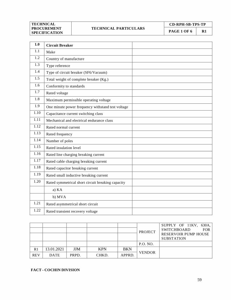
FACT - COCHIN DIVISION
59
TECHNICAL
PROCUREMENT
SPECIFICATION
TECHNICAL PARTICULARS CD-RPH-SB-TPS-TP
PAGE 1 OF 6 R1
1.0 Circuit Breaker
1.1 Make
1.2 Country of manufacture
1.3 Type reference
1.4 Type of circuit breaker (SF6/Vacuum)
1.5 Total weight of complete breaker (Kg.)
1.6 Conformity to standards
1.7 Rated voltage
1.8 Maximum permissible operating voltage
1.9 One minute power frequency withstand test voltage
1.10 Capacitance current switching class
1.11 Mechanical and electrical endurance class
1.12 Rated normal current
1.13 Rated frequency
1.14 Number of poles
1.15 Rated insulation level
1.16 Rated line charging breaking current
1.17 Rated cable charging breaking current
1.18 Rated capacitor breaking current
1.19 Rated small inductive breaking current
1.20 Rated symmetrical short circuit breaking capacity
a) KA
b) MVA
1.21 Rated asymmetrical short circuit
1.22 Rated transient recovery voltage
PROJECT
SUPPLY OF 11KV, 630A,
SWITCHBOARD FOR
RESERVOIR PUMP HOUSE
SUBSTATION
P.O. NO.
R1 13.01.2021 JJM KPN BKN
VENDOR
REV DATE PRPD. CHKD. APPRD.

FACT - COCHIN DIVISION
60
TECHNICAL
PROCUREMENT
SPECIFICATION
TECHNICAL PARTICULARS CD-RPH-SB-TPS-TP
PAGE 2 OF 6 R1
1.23 Rated making current (KA peak)
1.24 Rated short time current
a) 1 sec
b) 3 sec
1.25 Rated duty cycle
1.26 Opening time
1.27 Closing time
1.28 Total break time at rated short circuit capacity
1.29 Arc duration
1.30 Number of breaks per phase
1.31 Total length of break per phase
1.32 Type of main contacts
1.33 Type of arcing contacts
1.34 Type of arc control employed
1.35 Pole center to center distance
1.36 Number of aux. Contacts (NO+NC) (without
multiplying contactor)
1.37 Method of power closing offered
1.38 Normal voltage of the spring charging motor
1.39 Power at normal voltage required for spring
charging motor
1.40 Time taken to charge the spring completely by the
motor
1.41 Normal and minimum operating voltage of closing mechanism
1.42 Power at normal voltage required for closing coil
1.43 Power at normal voltage required for trip coil
1.44 Normal and minimum voltage required for trip coil
1.45 Closing coil voltage and power required to close the
breaker
1.46 Normal and minimum voltage required for operation
of solenoid closing mechanism

61
TECHNICAL
PROCUREMENT
SPECIFICATION
TECHNICAL PARTICULARS
CD-RPH-SB-TPS-TP
PAGE 3 OF 6 R1
1.47 Current at normal voltage, required for solenoid
operation
1.48 Short circuit type test certificate no. or report no.
1.49 Bus bars
1.50 Conformity to standards
1.51 Material and grade of bus bars
1.52 Type of busbar covering
1.53 Continuous current rating
1.54 Normal area (mm2)
1.55 Size of bus
a) Horizontal
b) Vertical
1.56 Colour coding
1.57 Type of insulation
1.58 Derating factor applied in view of PVC covering
1.59 Peak dynamic withstand capacity
1.60 Rated short time current for 1 second
1.61 Guaranteed temperature rise at rated current for bare bus bars
1.62 Details of bus bar supports
1.63 Guaranteed temperature rise at rated current for PVC covered bus bars
1.64 Whether short circuit type test certificates attached or
not
1.65 Clearance of bus bars in air
a) Phase to phase
b) Phase to earth
2.0 Current transformers
2.1 Conformity to standards
2.2 Make
FACT - COCHIN DIVISION
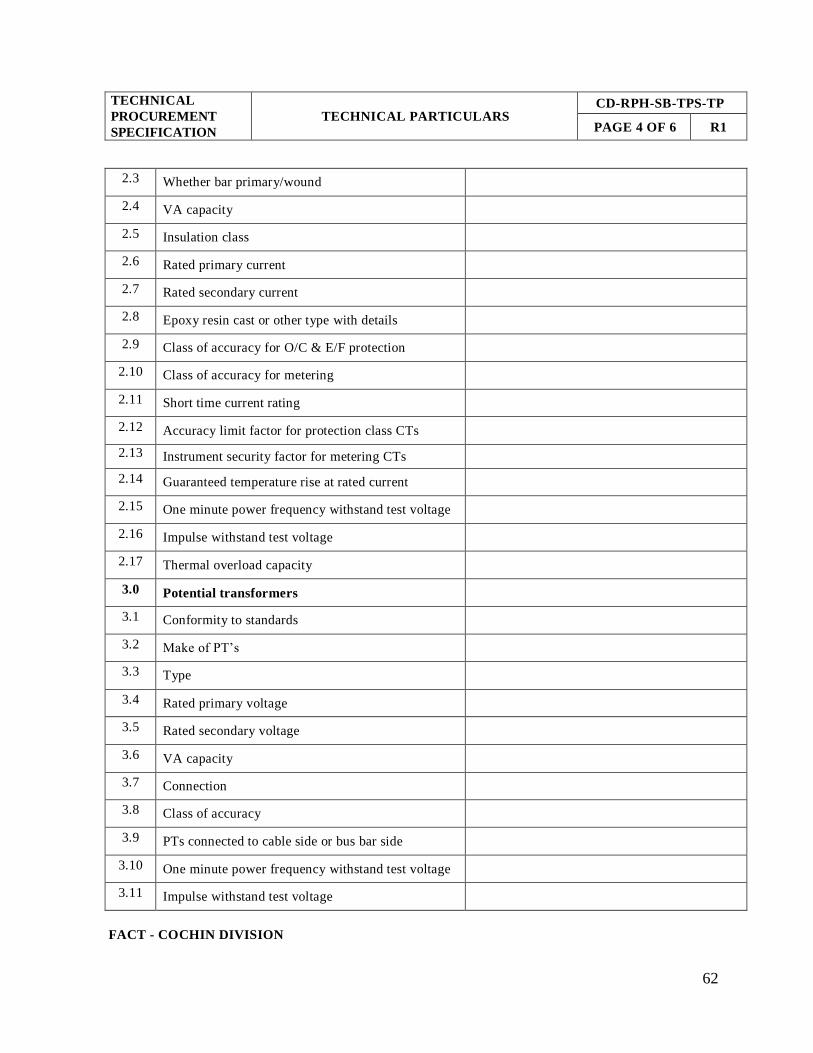
62
TECHNICAL
PROCUREMENT
SPECIFICATION
TECHNICAL PARTICULARS
CD-RPH-SB-TPS-TP
PAGE 4 OF 6 R1
2.3 Whether bar primary/wound
2.4 VA capacity
2.5 Insulation class
2.6 Rated primary current
2.7 Rated secondary current
2.8 Epoxy resin cast or other type with details
2.9 Class of accuracy for O/C & E/F protection
2.10 Class of accuracy for metering
2.11 Short time current rating
2.12 Accuracy limit factor for protection class CTs
2.13 Instrument security factor for metering CTs
2.14 Guaranteed temperature rise at rated current
2.15 One minute power frequency withstand test voltage
2.16 Impulse withstand test voltage
2.17 Thermal overload capacity
3.0 Potential transformers
3.1 Conformity to standards
3.2 Make of PT’s
3.3 Type
3.4 Rated primary voltage
3.5 Rated secondary voltage
3.6 VA capacity
3.7 Connection
3.8 Class of accuracy
3.9 PTs connected to cable side or bus bar side
3.10 One minute power frequency withstand test voltage
3.11 Impulse withstand test voltage
FACT - COCHIN DIVISION

63
TECHNICAL
PROCUREMENT
SPECIFICATION
TECHNICAL PARTICULARS
CD-RPH-SB-TPS-TP
PAGE 5 OF 6 R1
4.0 Protection Relays
4.1 Conformity to standards
4.2 Make
4.3 Withdrawal features provided or not
4.4 Mounting: Flush / Projection
5.0 Multi Function Meters
5.1 Conformity to standards
5.2 Make
5.3 Type
5.4 Mounting: Flush / projection
5.5 Size of meters
5.6 Class of accuracy
6.0 Indication Lamps
6.1 Conformity to standards
6.2 Make
6.3 Type
6.4 Watts rating at specified auxiliary voltage
7.0 Panel board
7.1 Material & area of cross section of conductor
between
a) Busbars and circuit breaker/switch or switch
fuse (if any) of each rating
b) Switch and fuses of each rating (if any)
7.2 Size & material of earth bus bar
7.3 Thickness of panel doors (mm)
7.4 Thickness of load bearing members (mm)
7.5 Thickness of base frame (mm)
FACT - COCHIN DIVISION
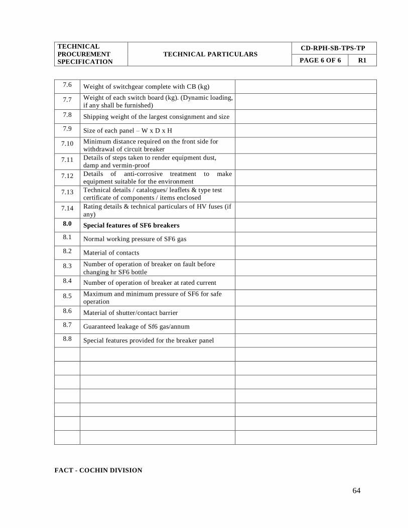
64
TECHNICAL
PROCUREMENT
SPECIFICATION
TECHNICAL PARTICULARS CD-RPH-SB-TPS-TP
PAGE 6 OF 6 R1
7.6 Weight of switchgear complete with CB (kg)
7.7 Weight of each switch board (kg). (Dynamic loading,
if any shall be furnished)
7.8 Shipping weight of the largest consignment and size
7.9 Size of each panel – W x D x H
7.10 Minimum distance required on the front side for
withdrawal of circuit breaker
7.11 Details of steps taken to render equipment dust,
damp and vermin-proof
7.12 Details of anti-corrosive treatment to make
equipment suitable for the environment
7.13 Technical details / catalogues/ leaflets & type test
certificate of components / items enclosed
7.14 Rating details & technical particulars of HV fuses (if
any)
8.0 Special features of SF6 breakers
8.1 Normal working pressure of SF6 gas
8.2 Material of contacts
8.3 Number of operation of breaker on fault before
changing hr SF6 bottle
8.4 Number of operation of breaker at rated current
8.5 Maximum and minimum pressure of SF6 for safe
operation
8.6 Material of shutter/contact barrier
8.7 Guaranteed leakage of Sf6 gas/annum
8.8 Special features provided for the breaker panel
FACT - COCHIN DIVISION
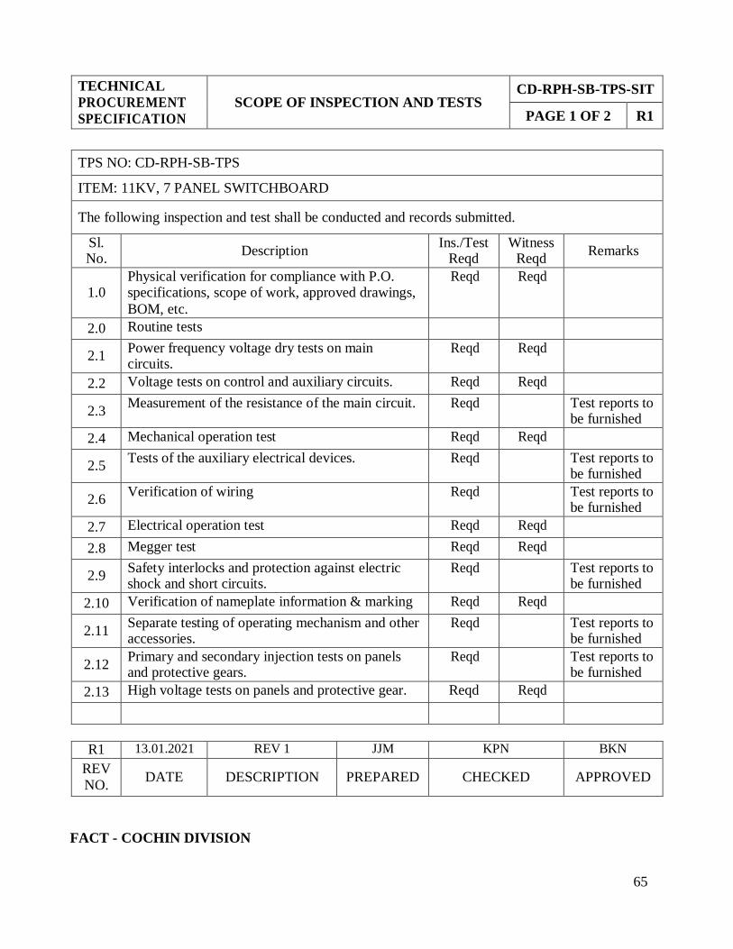
65
TECHNICAL
PROCUREMENT
SPECIFICATION
SCOPE OF INSPECTION AND TESTS
CD-RPH-SB-TPS-SIT
PAGE 1 OF 2 R1
TPS NO: CD-RPH-SB-TPS
ITEM: 11KV, 7 PANEL SWITCHBOARD
The following inspection and test shall be conducted and records submitted.
Sl. No.
Description Ins./Test
Reqd Witness
Reqd Remarks
1.0 Physical verification for compliance with P.O. specifications, scope of work, approved drawings,
BOM, etc.
Reqd Reqd
2.0 Routine tests
2.1 Power frequency voltage dry tests on main circuits.
Reqd Reqd
2.2 Voltage tests on control and auxiliary circuits. Reqd Reqd
2.3 Measurement of the resistance of the main circuit. Reqd Test reports to
be furnished
2.4 Mechanical operation test Reqd Reqd
2.5 Tests of the auxiliary electrical devices. Reqd Test reports to
be furnished
2.6 Verification of wiring Reqd Test reports to
be furnished
2.7 Electrical operation test Reqd Reqd
2.8 Megger test Reqd Reqd
2.9 Safety interlocks and protection against electric shock and short circuits.
Reqd Test reports to be furnished
2.10 Verification of nameplate information & marking Reqd Reqd
2.11 Separate testing of operating mechanism and other accessories.
Reqd Test reports to be furnished
2.12 Primary and secondary injection tests on panels and protective gears.
Reqd Test reports to be furnished
2.13 High voltage tests on panels and protective gear. Reqd Reqd
R1 13.01.2021 REV 1 JJM KPN BKN
REV
NO. DATE DESCRIPTION PREPARED CHECKED APPROVED
FACT - COCHIN DIVISION
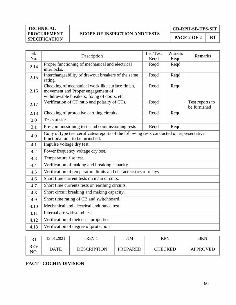
66
TECHNICAL
PROCUREMENT
SPECIFICATION
SCOPE OF INSPECTION AND TESTS
CD-RPH-SB-TPS-SIT
PAGE 2 OF 2 R1
Sl. No.
Description Ins./Test
Reqd Witness
Reqd Remarks
2.14 Proper functioning of mechanical and electrical interlocks.
Reqd Reqd
2.15 Interchangeability of drawout breakers of the same rating.
Reqd Reqd
2.16 Checking of mechanical work like surface finish, movement and Proper engagement of
withdrawable breakers, fixing of doors, etc.
Reqd Reqd
2.17 Verification of CT ratio and polarity of CTs. Reqd Test reports to
be furnished
2.18 Checking of protective earthing circuits Reqd Reqd
3.0 Tests at site
3.1 Pre-commissioning tests and commissioning tests Reqd Reqd
4.0 Copy of type test certificates/reports of the following tests conducted on representative functional unit to be furnished.
4.1 Impulse voltage dry test.
4.2 Power frequency voltage dry test.
4.3 Temperature rise test.
4.4 Verification of making and breaking capacity.
4.5 Verification of temperature limits and characteristics of relays.
4.6 Short time current tests on main circuits.
4.7 Short time currents tests on earthing circuits.
4.8 Short circuit breaking and making capacity.
4.9 Short time rating of CB and switchboard.
4.10 Mechanical and electrical endurance test.
4.11 Internal arc withstand test
4.12 Verification of dielectric properties
4.13 Verification of degree of protection
R1 13.01.2021 REV 1 JJM KPN BKN
REV
NO. DATE DESCRIPTION PREPARED CHECKED APPROVED
FACT - COCHIN DIVISION

67
TECHNICAL
PROCUREMENT
SPECIFICATION
SPARES LIST CD-RPH-SB-TPS-SL
PAGE 1 OF 1 R1
TPS NO: CD-RPH-SB-TPS
Sl. No. Description Quantity Unit price
Total price
1.0 11KV, 7 PANEL SWITCH BOARD SPARES
1.1 Breaker Pole 3 Nos.
1.2 PT secondary fuse
3 Nos
1.3 11kV side PT fuse 3 Nos.
1.4 Breaker control switch 2 Nos.
1.5 Closing coil 2 Nos.
1.6 Tripping coil 2 Nos.
1.7 Closing spring 1 No.
1.8 Tripping spring 1 No
1.9 Spring charging motor 1 No.
1.10 Breaker rack-in handle 1 No.
1.11 Manual spring charging handle 1 No.
1.12 Bus support insulator (11kV)
2 Nos. of each rating
1.13 LED Indication lamps
3 Nos. of each rating
1.14 Numerical feeder protection and control relay 1 No.
1.15 Numerical transformer protection and control relay
1 No.
1.16 Anti pumping relay 1 No.
1.17 DC failure relay 1 No.
R1 13.01.2021 REV 1 JJM KPN BKN
REV NO.
DATE DESCRIPTION PREPARED CHECKED APPROVED
FACT - COCHIN DIVISION

68
TECHNICAL
PROCUREMENT
SPECIFICATION
SUB VENDOR LIST CD-RPH-SB-TPS-SVL
PAGE 1 OF 1 R1
R1 13.01.2021 REV 1 JJM KPN BKN
REV
NO. DATE DESCRIPTION PREPARED CHECKED APPROVED
FACT - COCHIN DIVISION
INSRUMENT TRANSFORMERS MULTI FUNCTION METER
AUTOMATIC ELECTRIC SCHNEIDER ELECTRIC
PRAGATHI SIEMENS
SILKANS ABB
SIEMENS AUOTMATIC ELECTRIC
ALSTOM /AREVA RISHAB
ABB MECO
ECS SELEC
INTRANS HRC FUSES
KAPPA SIEMENS
SCHNEIDER ELECTRIC L&T
PROTECTIVE RELAYS (NUMERICAL) HAVELLS
ALSTOM/AREVA ALSTOM
ABB
C &S
SIEMENS
SCHNEIDER ELECTRIC GE
EASUN REYROLLE
CONTROL & SELECTOR SWITCHES
KAYCEE ALSTOM
SULZER SIEMENS
EASUN REYROLLE
KHAITAN
JYOTI
ABB
L&T
SCHNEIDER ELECTRIC
Note: Panel manufactures have a freedom for using their own type tested components and NABL lab certified
components in offered panels.

69
TECHNICAL
PROCUREMENT
SPECIFICATION
VENDOR’S EXPERIENCE - FORMAT
CD-RPH-SB-TPS-VE
PAGE 1 OF 1 R1
Sl.
no.
Client
Description of order
Value of order
along with size &
quantity
Month &
year of
supply
Name, Address,
Telephone, E-mail, Fax
of the contact person
1
2
3
4
5
Name of Vendor:
Date:
Name & Designation
Signature & Seal
FACT - COCHIN DIVISION
Vendor shall furnish here a list of similar orders executed by him for reference.
TPS NO: CD-RPH-SB-TPS
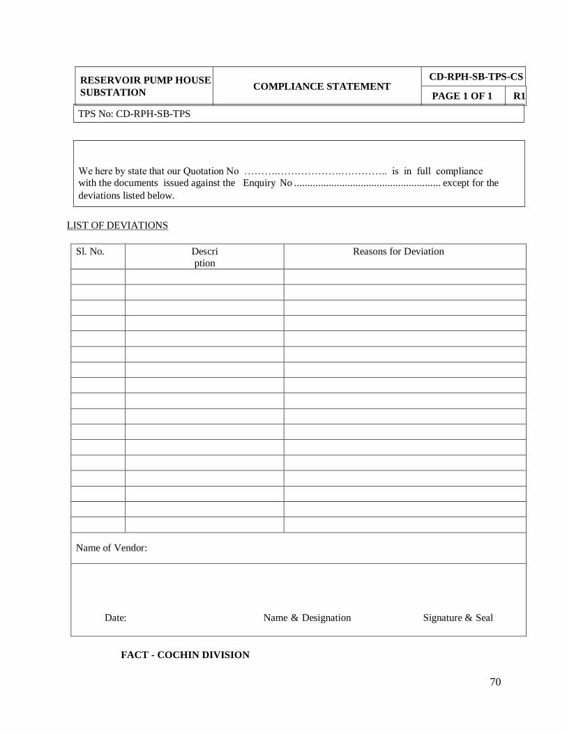
70
RESERVOIR PUMP HOUSE
SUBSTATION
COMPLIANCE STATEMENT
CD-RPH-SB-TPS-CS
PAGE 1 OF 1 R1
LIST OF DEVIATIONS
Sl. No. Descri
ption
Reasons for Deviation
Name of Vendor:
Date: Name & Designation Signature & Seal
FACT - COCHIN DIVISION
We here by state that our Quotation No ……….……………….………….. is in full compliance
with the documents issued against the Enquiry No ....................................................... except for the
deviations listed below.
TPS No: CD-RPH-SB-TPS

PTR: 11KV/V3 /110/V3
CORE 1: 50VA CL: 1
CTR: 400/ 1-1A
CORE 1: 10VA CL: 1.0
CORE 2: 10VA CL: 5P10
1*3C*185 SQ.MM
XLPE, ALU
INCOMER FROM THERMAL
SF6 /
VACUUM CB
CTR: 200/ 1-1A
CORE 1: 10VA CL: 1.0
CORE 2: 10VA CL: 5P10
1*3C*185 SQ.MM
XLPE, ALU
TYPE 3
SUBSTATION
CTR: 200/ 1-1A
CORE 1: 10VA CL: 1.0
CORE 2: 10VA CL: 5P10
1R*3C*185 SQ.MM
XLPE, ALU
CORE-1CORE-2
CORE-2CORE-1
CORE-2CORE-1
PANEL NO-2
PANEL NO-3
RPH TR-1
2500 KVA
11KV/3.3KV
DELTA/STAR
500 MVA 11KV, 7 PANEL
SWITCH BOARD
SF6 /
VACUUM CB
SF6 /
VACUUM CB
CTR: 200/ 1-1A
CORE 1: 10VA CL: 1.0
CORE 2: 10VA CL: 5P10
1*3C*185 SQ.MM
XLPE, ALU
CTR: 200/ 1-1A
CORE 1: 10VA CL: 1.0
CORE 2: 10VA CL: 5P10
1R*3C*185 SQ.MM
XLPE, ALU
CORE-2CORE-1
CORE-2CORE-1
PANEL NO-6
SF6 /
VACUUM CB
3A
RPH TR-2
1600 KVA
11KV/3.3KV
DELTA/STAR
BUS COUPLER PANEL
SF6 / VACCUM CB
PANEL NO-5
SF6 /
VACUUM CB
SPARE
PANEL NO-4
PTR: 11KV/V3 /110/V3
CORE 1: 50VA CL: 1
3A
CTR: 400/ 1-1A
CORE 1: 10VA CL: 1.0
CORE 2: 10VA CL: 5P10
CORE-1CORE-2
1*3C*185 SQ.MM
XLPE, ALU
RPH LAKE VIEW TIE
PANEL NO-1
PANEL NO-7
TYPICAL LAYOUT
TECHNICAL
PROCUREMENT
SPECIFICATION
PAGE 1 OF 1
TYPI
CA
L SI
NG
LE L
INE
DIA
GR
AM
OF
11 K
V ,
7 PA
NEL
SW
ITC
H B
OA
RD
SF6 /
VACUUM CB