Embed Size (px)
DESCRIPTION
British Fire Code
Citation preview

A Reference numberISO/TR 13387-6:1999(E)
TECHNICALREPORT
ISO/TR13387-6
First edition1999-10-15
Fire safety engineering —
Part 6:Structural response and fire spread beyond theenclosure of origin
Ingénierie de la sécurité contre l'incendie —
Partie 6: Réponse structurelle et propagation du feu au-delà de l'enceinted'origine

ISO/TR 13387-6:1999(E)
© ISO 1999
All rights reserved. Unless otherwise specified, no part of this publication may be reproduced or utilized in any form or by any means, electronicor mechanical, including photocopying and microfilm, without permission in writing from the publisher.
International Organization for StandardizationCase postale 56 • CH-1211 Genève 20 • SwitzerlandInternet [email protected]
Printed in Switzerland
ii
Contents
1 Scope ........................................................................................................................ ................................................1
2 Normative references ......................................................................................................... .....................................1
3 Terms and definitions ........................................................................................................ .....................................2
4 Symbols and abbreviated terms ................................................................................................ ............................3
5 Subsystem 3 of the total design system ....................................................................................... ........................3
6 Subsystem 3 evaluations...................................................................................................... ..................................5
6.1 General.................................................................................................................... ...............................................5
6.2 Thermal response........................................................................................................... ......................................5
6.3 Mechanical response........................................................................................................ ....................................7
6.4 Fire spread................................................................................................................ .............................................9
7 Engineering methods .......................................................................................................... ..................................13
7.1 General.................................................................................................................... .............................................13
7.2 Estimation formulae ........................................................................................................ ...................................13
7.3 Computer models ............................................................................................................ ...................................13
7.4 Experimental methods ....................................................................................................... ................................14
8 Guidance for setting criteria................................................................................................ .................................14
Bibliography ................................................................................................................... ...........................................16
© ISO ISO/TR 13387-6:1999(E)
iii
Foreword
ISO (the International Organization for Standardization) is a worldwide federation of national standards bodies (ISOmember bodies). The work of preparing International Standards is normally carried out through ISO technicalcommittees. Each member body interested in a subject for which a technical committee has been established hasthe right to be represented on that committee. International organizations, governmental and non-governmental, inliaison with ISO, also take part in the work. ISO collaborates closely with the International ElectrotechnicalCommission (IEC) on all matters of electrotechnical standardization.
The main task of ISO technical committees is to prepare International Standards, but in exceptional circumstances atechnical committee may propose the publication of a Technical Report of one of the following types:
type 1, when the required support cannot be obtained for the publication of an International Standard, despiterepeated efforts;
type 2, when the subject is still under technical development or where for any other reason there is the futurebut not immediate possibility of an agreement on an International Standard;
type 3, when a technical committee has collected data of a different kind from that which is normally publishedas an International Standard (“state of the art“, for example).
Technical Reports of types 1 and 2 are subject to review within three years of publication, to decide whether theycan be transformed into International Standards. Technical Reports of type 3 do not necessarily have to bereviewed until the data they provide are considered to be no longer valid or useful.
ISO/TR 13387-6, which is a Technical Report of type 2, was prepared by Technical Committee ISO/TC 92, Firesafety, Subcommittee SC 4, Fire safety engineering.
It is one of eight parts which outlines important aspects which need to be considered in making a fundamentalapproach to the provision of fire safety in buildings. The approach ignores any constraints which might apply as aconsequence of regulations or codes; following the approach will not, therefore, necessarily mean compliance withnational regulations.
ISO/TR 13387 consists of the following parts, under the general title Fire safety engineering:
Part 1: Application of fire performance concepts to design objectives
Part 2: Design fire scenarios and design fires
Part 3: Assessment and verification of mathematical fire models
Part 4: Initiation and development of fire and generation of fire effluents
Part 5: Movement of fire effluents
Part 6: Structural response and fire spread beyond the enclosure of origin
Part 7: Detection, activation and suppression
Part 8: Life safety — Occupant behaviour, location and condition

ISO/TR 13387-6:1999(E) © ISO
iv
Introduction
An important feature of design for fire safety, whether it is undertaken employing prescriptive regulations or firesafety engineering principles, is to ensure that building elements prevent (or delay) the spread of fire and prevent(or delay) structural failure. Measures must be taken to ensure the spread of fire and structural failure do notthreaten the lives of occupants and firefighters, or compromise other fire safety objectives.
In prescriptive fire safety design, extensive use is made of the fire resistance of building elements as determined bythe standard fire resistance test ISO 834-1. Inherent in this test are criteria concerned with load-bearing capacity,integrity and thermal insulation. Fire resistance requirements may be prescribed in national regulations and codesaccording to the use of the building, the size of fire compartments and the height of the building.
Design may also be undertaken employing fire safety engineering principles in which neither the temperature-timecurve nor the duration of the exposing fire are prescribed. Instead, pertinent characteristics of the exposing fire arecalculated to be representative of one (or several) fire scenarios envisioned for the building. The thermal andmechanical response of building elements subjected to such exposing fires are then calculated. Finally, theperformance of building elements (specifically their ability to inhibit fire spread and structural failure) are assessedusing criteria which, depending on the conditions at hand, may differ from the fire resistance criteria withinISO 834-1.
This part of ISO/TR 13387 is intended for use together with the other Technical Reports as described in clause 5.For some applications however this document alone may be sufficient.
Clause 6 describes and provides guidance on the approaches available to characterize the physical and chemicalprocesses which govern the thermal and mechanical responses of building elements exposed to fire.
Clause 7 is a discussion of engineering methods to predict the thermal and mechanical response of buildingelements exposed to fire and thereby to evaluate the potential for fire spread and structural failure. It should benoted that whatever method is selected, it should be assessed and verified using the principles documented inISO/TR 13387-3. Furthermore, special care should be taken when using input data published in the literature. Thequantitative information may be related to specific test conditions and/or specific commercial products, and theapplication of the data under different conditions may result in significant errors.
Finally, in clause 8, guidance on interpreting the results of an analysis of the potential of structural failure and firespread is provided. This includes guidance on the selection of criteria for assessing the effectiveness of fire safetymeasures meant to reduce the potential of structural failure or fire spread. The latter is only possible if the objectivesof fire safety design have been clearly specified.

TECHNICAL REPORT © ISO ISO/TR 13387-6:1999(E)
1
Fire safety engineering —
Part 6:Structural response and fire spread beyond the enclosure of origin
1 Scope
This part of ISO/TR 13387 is intended to provide general guidance on the use of engineering methods for theprediction of fire spread within and between buildings, and for the prediction of the response of a structure exposedto fire. The report is not intended as a detailed technical design guide, but could be used as the basis fordevelopment of such a guide.
This part of ISO/TR 13387 provides a framework for critically reviewing the suitability of an engineering method forassessing the potential for fire spread and for fire damage to a building's structure. It also provides guidance forassessing the effectiveness of fire safety measures meant to reduce these potentials.
2 Normative references
The following normative documents contain provisions which, through reference in this text, constitute provisions ofthis part of ISO/TR 13387. For dated references, subsequent amendments to, or revisions of, any of thesepublications do not apply. However, parties to agreements based on this part of ISO/TR 13387 are encouraged toinvestigate the possibility of applying the most recent editions of the normative documents indicated below. Forundated references, the latest edition of the normative document referred to applies. Members of ISO and IECmaintain registers of currently valid International Standards.
ISO 834-1:1999, Fire-resistance tests — Elements of building construction — Part 1: General requirements.
ISO 7345:1987, Thermal insulation — Physical quantities and definitions.
ISO/TR 10158:1991, Principles and rationale underlying calculation methods in relation to fire resistance ofstructural elements.
ISO/TR 12470:1998, Fire resistance tests — Guidance on the application and extension of results.
ISO/TR 13387-1, Fire safety engineering — Part 1: Application of fire performance concepts to design objectives.
ISO/TR 13387-2, Fire safety engineering — Part 2: Design fire scenarios and design fires.
ISO/TR 13387-3, Fire safety engineering — Part 3: Assessment and verification of mathematical fire models.
ISO/TR 13387-4, Fire safety engineering — Part 4: Initiation and development of fire and generation of fire effluents.
ISO/TR 13387-5, Fire safety engineering — Part 5: Movement of fire effluents.

ISO/TR 13387-6:1999(E) © ISO
2
ISO/TR 13387-7, Fire safety engineering — Part 7: Detection, activation and suppression.
ISO/TR 13387-8, Fire safety engineering — Part 8: Life safety — Occupant behaviour, location and condition.
ISO 13943, Fire safety — Vocabulary.
3 Terms and definitions
For the purposes of this part of ISO/TR 13387, the definitions given in ISO 13943, ISO/TR 13387-1 and thefollowing apply.
3.1building elementintegral component of the structure or fabric of a building, including floors, walls, beams, columns, doors, etc.complete with penetrations, but does not include building contents
3.2enclosurespace defined by boundary elements
3.3integrityability of a separating element, when exposed to fire on one side, to prevent the passage of flames and hot gases orthe occurrence of flames on the unexposed side
3.4load-bearing capacityability of a building element (or structure) to sustain applied actions (loads) when exposed to fire
3.5mechanical responsemeasure of fire induced changes to the deflection, stiffness and load-bearing capacity of building elements and thedevelopment of openings (cracks) in building elements during fire exposure as a result of the shrinkage (expansion)of materials, spalling, delamination, etc.
3.6thermal diffusivitythermal conductivity divided by the density and specific heat, expressed in m2·s-1, given by k = k/(r·c)
3.7thermal inertiaproduct of thermal conductivity, density and specific heat (square of thermal effusivity according to ISO 7345), givenby k·r·c,
It is expressed in J2·m-4·K-2·s-1.
3.8thermal insulationthe ability of a separating element, when exposed to fire on one side, to prevent the transmission of excessive heat
3.9thermal responsea measure of:
a) fire induced changes to the temperature profile within building elements; and
b) the development of openings in building elements during fire exposure as a result of the melting of materials

© ISO ISO/TR 13387-6:1999(E)
3
4 Symbols and abbreviated terms
c specific heat of a material, expressed in J·kg-1·K-1
k thermal conductivity, expressed in W·m-1·K-1
k thermal diffusivity, expressed in m2·s-1
r density, expressed in kg·m-3
5 Subsystem 3 of the total design system
The approach adopted in this part of ISO/TR 13387 is to acknowledge that assessment of structural response andfire spread addresses only a subsection of the global objectives of fire safety design. Global design, described inmore detail in the framework document, ISO/TR 13387-1, is divided into subsystems. The key principles of theglobal design approach are that interdependencies among the subsystems are evaluated and that pertinentconsiderations for each subsystem are identified. Structural response and fire spread is subsystem 3 (SS3) of thetotal fire safety design system.
In the framework document, global fire safety design is illustrated by an information bus analogy. The informationbus has three layers: global information, evaluations and process buses. The global information includes data whichare either transferred among subsystems or employed to make engineering decisions. SS3 links with the globalinformation are shown in Figure 1. The second layer of the bus system depicts the evaluations which must beundertaken within SS3 to evaluate structural response and fire spread. The third layer elucidates the fundamentalprocesses which come into play in each evaluation undertaken within SS3.
SS3 draws on other subsystems for certain input data and generates output data which are used by yet othersubsystems. For example, SS1 provides predictions of the temperature and heat flux history (thermal profile) in theenclosure of concern. These data along with the description of building assemblies (building parameters) areemployed by SS3 to predict the likelihood (and time) of fire spread, and the likelihood (and time) of structural failure.Once a prediction has been made “output” data describing the building condition are placed on the globalinformation bus. Building condition data may subsequently become “input” data for evaluations undertaken by SS1and SS2 to calculate, for example, the potential for fire spread (and the subsequent fire size).
The transfer of data between the global information bus and the evaluations undertaken in SS3 is depicted explicitlyin Figure 1. As Figure 1 indicates it is necessary to calculate (evaluate) the thermal response and mechanicalresponse of building systems and then determine whether fire spread will occur. Guidance on undertaking suchcalculations is given in clause 6.
The fundamental processes which come into play in these evaluations are also depicted in Figure 1. An engineeringanalysis will incorporate these fundamental processes to an appropriate level of rigour as discussed in clause 6.
It should be noted that Figure 1 has been constructed to elucidate the process involved in undertaking an evaluationof the potential for structural failure or fire spread. It is not intended to include all possible phenomena.

ISO/TR 13387-6:1999(E) © ISO
4
ISO TC 92/SC 4 FIRE SAFETY ENGINEERING BUS SYSTEM
Subsystem 3 (SS3) — Structural response and fire spread beyond the enclosure of origin
Figure 1 — Illustration of the global information, evaluation and process buses for SS3

© ISO ISO/TR 13387-6:1999(E)
5
6 Subsystem 3 evaluations
6.1 General
In this clause, guidance on predicting and evaluating the thermal and mechanical response of building elements andstructures exposed to fire are discussed. Guidance on assessing whether fire spread will occur is also provided.The input data required to undertaken such evaluations and the possible output information are identified. Wherepossible, reference is made to literature which provides a more detailed discussion of the material presented in thisclause.
6.2 Thermal response
6.2.1 Role in fire safety engineering design
This clause provides an overview of the assessment of the thermal response of building elements which are in oneway or other exposed to heating from fire. The exposing fire may be a localized fire within an enclosure, a post-flashover enclosure fire, or perhaps an external fire. The nature of the exposing fire will have already been derivedby SS1 or possibly specified as a design fire by ISO/TR 13387-2.
An accurate prediction of the thermal response of building elements exposed to fire is essential in fire safetyengineering design. In the first instance, it allows for an assessment of the degree of thermal damage that may besustained by building elements exposed to fire. This may be particularly important if a building is to be designed sothat it can be re-used following a fire. Of more immediate concern, prediction of the thermal response of buildingelements is the first step in the assessment of their mechanical response and ultimately the potential for structuralfailure and/or fire spread.
Detailed discussions of the mechanical response and potential for fire spread are provided in 6.3 and 6.4respectively. However, it note that for some applications an assessment of the thermal response of buildingelements coupled with well-defined performance criteria may suffice. This may be the case, for example, if astructural member can be assumed to fail when it reaches a specific temperature as is often assumed for structuralsteel elements. It may also be the case if it can be assumed that the spread of fire from one enclosure to anothermay occur because of either the excessive transmission of heat through enclosure boundaries or because ofopenings created by the melting of materials as both of these phenomena can also be tied to temperature risecriteria. The question of establishing appropriate thermal criteria is briefly discussed in clause 8.
6.2.1.1 Input
As depicted in Figure 1, evaluation of the thermal response of building elements requires the following input datafrom the global information bus:
building parameters (dimensions, locations, thermophysical and thermochemical properties of buildingelements);
size of fire/smoke (for localized or external fires: physical size and relative location of fire to key buildingelements);
thermal (for all fires: the temperature-time profile of fire gases and the heat flux impinging on buildingelements);
pressure / velocity (the velocity of the fire gases may be needed to assess convective heat transfer from thefire to building elements); and
effluent species (smoke concentrations effect the emissivity of the fire gases. The emissivity may be needed toassess radiative heat transfer from the fire to building elements).
ISO/TR 13387-6:1999(E) © ISO
6
6.2.1.2 Output
Once the evaluation of the thermal response of building elements is completed, the following data are passed to theglobal information bus:
building condition (temperature-time profile within and on the surface of building elements).
This output also becomes input for assessing the mechanical response of building elements and the potential forfire spread.
6.2.2 Modelling the thermal response of building elements
As indicated in 6.2.1.1, to model the thermal response of building elements, a reasonably detailed description of theexposing fire is necessary. This document is intended to be used as part of a fire safety engineering assessment inwhich SS1 has first calculated the pertinent properties of the exposing fire (whether it be an enclosure fire, alocalized fire or an external fire). There are, however, applications for which the exposing fire can be chosen from aset of design fires. Care must be exercised when selecting an appropriate design fire as some constructions may besensitive to high temperatures whereas others may be sensitive to high rates of temperature rise or to the durationof exposure. Further guidance on the use of design fires is found in ISO/TR 13387-2.
Once the exposing fire has been chosen an assessment of the thermal response of building elements can begin(see Figure 1). The calculation of heat transfer to and within the building elements undertaken by SS3 will need tobe more detailed than the calculation already undertaken by SS1 where it was the temperature of the fire gases thatwas of primary interest.
If a building element is in direct contact with fire gases (for example, in a post-flashover enclosure fire), heat istransferred to exposed surfaces of the element by means of radiation (see reference [1] in the bibliography) andconvection (see reference [2]). On the other hand, if a building element is some distance from flames or hot gases(for example, for exposure to fire in a neighbouring building), “exposed” surfaces may be heated by radiation butcooled by convection. Engineering methods for modelling radiative and convective heat transfer for fire safetyengineering calculations are readily available (see references [1] and [2]).
In either case, heat is transferred from the hot surface deeper into the element by means of heat conduction (seereference [3]). As heat is conducted into the element, any absorbed water is vaporized (a phase change) and theelement itself may experience melting (a phase change) or thermal degradation. These processes are commonlyendothermic and hence slow down heat transmission. The vapours generated by vaporization of water and bythermal degradation of the element will migrate through the element further impacting on the heat transfer process.In principle, then, heat transfer and mass transfer (gas flow) are coupled. The equations governing these processesare complex and can only be solved by the use of numerical methods.
For some materials, the internal processes discussed above are not present or do not unduly impact upon heat flowso that heat transfer through the material can be assumed to obey the 3-dimensional heat conduction (seereference [3]). Nonetheless, the material's thermal conductivity (k), specific heat (c) and perhaps even density (r)are commonly temperature dependent. Despite these simplifications, the heat conduction equation with temperaturedependent coefficients can also only be solved by the use of numerical methods.
Analysis can be further simplified if the material's thermal properties (k, c and r) can be assumed to be constant (orat least can be replaced by an average value) over the temperature range of interest. Due to the complex nature ofradiative heating at the surface (boundary conditions) the heat conduction equation can still only be solved explicitlyby the use of numerical methods. Nonetheless, the structure of the equation reveals interesting dependencies onthe thermal properties. For example, in the early stages of the heating, the increase of the temperature of a surfaceexposed to radiative and/or convective heating as a function of time is proportional to (k·r·c)1/2; that is, to theinverse of the square root of the thermal inertia. On the other hand, the time-dependent temperature profile withinthe material can be shown to depend upon the material's thermal diffusivity k.
For materials which have very large thermal conductivity or which are very thin, it is sometimes possible tocompletely ignore heat conduction. In such cases, a lumped heat capacity model can be constructed whereby theentire element is assumed to be at a uniform temperature. Nonetheless, the element is still heated at the surface byradiation and convection.

© ISO ISO/TR 13387-6:1999(E)
7
Further discussion of engineering methods for modelling the thermal response of building elements exposed to fireis provided in clause 7 of this part of ISO/TR 13387 and in ISO/TR 10158.
6.3 Mechanical response
6.3.1 Role in fire safety engineering design
This subclause provides an overview of the assessment of the mechanical response of building elements and thebuilding structure when exposed to heating from fire. This analysis is undertaken using as input data the time-dependent temperature profiles within elements which have been calculated following the procedures outlined in6.2.
The term mechanical response is used to denote two important facets of a building element's response to fire.Firstly, it is a measure of fire induced changes to the deflection, stiffness and load-bearing capacity of the element.Secondly, it is a measure of the development of openings (cracks) in the element as a result of the shrinkage(expansion) of materials, spalling, delamination, etc.
An accurate prediction of the mechanical response of building elements exposed to fire is essential in fire safetyengineering design. In the first instance, it allows for an assessment of the degree of mechanical damage that maybe sustained by building elements exposed to fire. This may be particularly important if a building is to be designedso that it can be re-used following a fire. Of more immediate concern, prediction of the mechanical response ofbuilding elements is necessary step in the assessment of the potential for structural failure and/or fire spread.
Detailed discussions of the potential for fire spread are provided in 6.4. However, it should be noted that for someapplications an assessment of the thermal and, then, mechanical response of building elements coupled with well-defined performance criteria may suffice. This may be the case, for example, if a structural member can be shownto undergo excessive deflection. It may also be the case if it can be assumed that the spread of fire from oneenclosure to another may occur because of openings created by the shrinkage (expansion) of materials, spalling,delamination, etc. The question of establishing appropriate criteria is briefly discussed in clause 8.
6.3.1.1 Input
As depicted in Figure 1, evaluation of the mechanical response of building elements requires the following inputdata from the global information bus:
building parameters (mechanical properties of building elements, structural loads supported by buildingelements);
building condition (temperature-time profile within and on the surface of building elements); and
pressure and/or velocity (pressure distributions may have an impact on integrity and structural performance).
6.3.1.2 Output
Once the evaluation of the mechanical response of building elements is completed, the following data are passed tothe global information bus:
building condition (integrity of building elements and load-bearing capacity of building elements).
This output also becomes input for assessing the potential for structural collapse and fire spread.
6.3.2 Modelling the mechanical response of building elements
As indicated in 6.3.1.1, to model the mechanical response of individual building elements or of the building structure,the time-dependent temperature profiles within the elements are necessary. Although it is likely that in a fire safetyengineering analysis these profiles will have been calculated following the procedures outlined in 6.2, such profilesare also available in graphical form for some elements exposed to the standard temperature-time curve defined inISO 834-1 and for certain simulated natural fires.

ISO/TR 13387-6:1999(E) © ISO
8
The mechanical properties of a building element, such as its modulus of elasticity or its yield stress, can be bothtemperature and thermal history dependent. Assessment of the structural response (in particular, assessment ofthermal expansion, deflections or load bearing capacity) is often undertaken by incorporating the mechanicalproperties of materials at elevated temperatures into traditional (room-temperature) structural analysis (seereference [4]). The assessment of the structural response of building elements exposed to fire is described in detailin ISO/TR 10158.
Modelling the integrity of building elements, that is, the development of openings (cracks) in an element as a resultof the shrinkage (expansion) of materials, spalling, delamination, etc., is not very advanced. In fire safetyengineering calculations, this behaviour is often inferred on the basis of the element's performance in the standardfire resistance tests.
6.3.3 Effect of continuity and restraint
In modelling the mechanical response of load-bearing building elements, the restraint conditions experienced byelements must be properly treated.
Most fire resistance furnaces suffer limitations on the size of specimen that may be tested and the arrangements forimposing loads. Hence it is generally only possible to test specimens with idealized end conditions. Testingstandards recognize this fact. In fire safety engineering calculations, structural elements need not be treated inisolation from one another so that the mechanical response of the member will be influenced by the effects ofcontinuity and restraint from the surrounding structure.
Structural continuity allows redistribution of loads in the event of fire, which enhances the performance of theindividual element. While restraint may not significantly alter the ultimate load-bearing capacity of the element underfire exposure, it will generally reduce its deflection. Full (or 100%) restraint allows large forces to develop in heatedmembers due to restrained thermal expansion. Such forces which are often referred to as “thermal thrusts” caninduce failure. However, restraint is generally beneficial. For example, in ISO 834-1 tests, the optimum fireresistance of flexural concrete members have been observed when tested under imposed end restraints of between20 % and 80 %.
Restraint has two effects on the performance of columns in fire. Firstly, the resistance to free thermal expansiongenerates compressive forces within the column which reduce the rate of strength and stiffness loss at elevatedtemperature. Secondly, the failure mode of restrained columns may change from being a sudden buckling collapseto being one of progressively increasing deformation where load-bearing capacity is limited by strain capacity.
A further matter for consideration is that thermal gradients through the thickness of heated structural members cangenerate internal stresses as the thermal expansion of the hotter edge fibres is restrained by the cooler core. Themagnitude of such stresses is dependent on the thermal properties of the material being heated. The effect is ofparticular concern for concrete members where high local surface stress levels can result in explosive spalling.
The mathematical representation of the behaviour of building structures exposed to fire needs more research andvalidation.
6.3.4 Structural failure
An important feature of design for fire safety is to ensure that structural failure does not threaten the safety ofoccupants and firefighters, or compromise other fire safety objectives. Building regulations often rely on structuralfire resistance requirements to prevent (or delay) structural failure.
Structural failure occurs when a building element (or structure) is no longer able to sustain applied actions (loads)when exposed to fire. Its load-bearing capacity has been compromised to the point that the element collapses orexperiences excessive deflection.
Before the potential for structural failure can be determined, an assessment of the mechanical response of buildingelements (or structures) exposed to fire must be undertaken following 6.3.2. Of particular interest are the fireinduced changes to the deflection, stiffness and load-bearing capacity of the elements. Knowledge of themechanical response of building elements coupled with well-defined performance criteria allow for a determination
© ISO ISO/TR 13387-6:1999(E)
9
of whether structural failure will occur. The question of establishing appropriate criteria is briefly discussed inclause 8.
6.4 Fire spread
6.4.1 Role in fire safety engineering design
An important feature of design for fire safety is to ensure that the spread of fire does not threaten the safety ofoccupants and firefighters, or compromise other fire safety objectives. National building regulations often rely uponcompartmentation to prevent (or delay) fire spread within a building. This entails dividing a building intocompartments separated from one another by building elements with prescribed fire resistance ratings. The intent ofthis strategy is to confine fire to the compartment of origin and to keep fire from entering the escape routes.
Fire spread within a building can occur through openings existing before the fire or as a result of a thermal insulationfailure, an integrity failure or a structural failure.
Thermal insulation failure occurs when a separating element exposed to fire on one side transmits excessive heatto the unexposed side. As a consequence, fire spreads from the enclosure of fire origin through the separatingelement to a neighbouring enclosure.
Integrity failure occurs when a separating element exposed to fire on one side permits the passage of flames andhot gases or permits ignition into flames on the unexposed side. As a consequence, fire spreads from the enclosureof fire origin through the separating element to a neighbouring enclosure. Integrity failure may arise as the result ofthe development of cracks or fissures.
Structural failure occurs when a building element (or structure) is no longer able to sustain applied actions (loads)when exposed to fire. Its load-bearing capacity has been compromised to the point that the element collapses orexperiences excessive deflection.
There are other mechanisms of fire spread which must be considered. Flame spread along a facade can cause fireto spread from one floor to another. Fire may spread from building to building by means of radiant-heat transfer,direct flame impingement and/or flying brands.
6.4.1.1 Input
The evaluation of the potential of fire spread depends on the thermal and mechanical responses of buildingelements as well as any inadequacies resulting from design or poor maintenance. The evaluation depends on thefollowing input data from the global information bus:
building condition (temperature-time profile within and on the surface of building elements, integrity of buildingelements, load-bearing capacity of building elements).
6.4.1.2 Output
Once the evaluation of the potential fire spread is completed, the following data are passed into the information bus:
size of fire and/or smoke (area involved in fire).
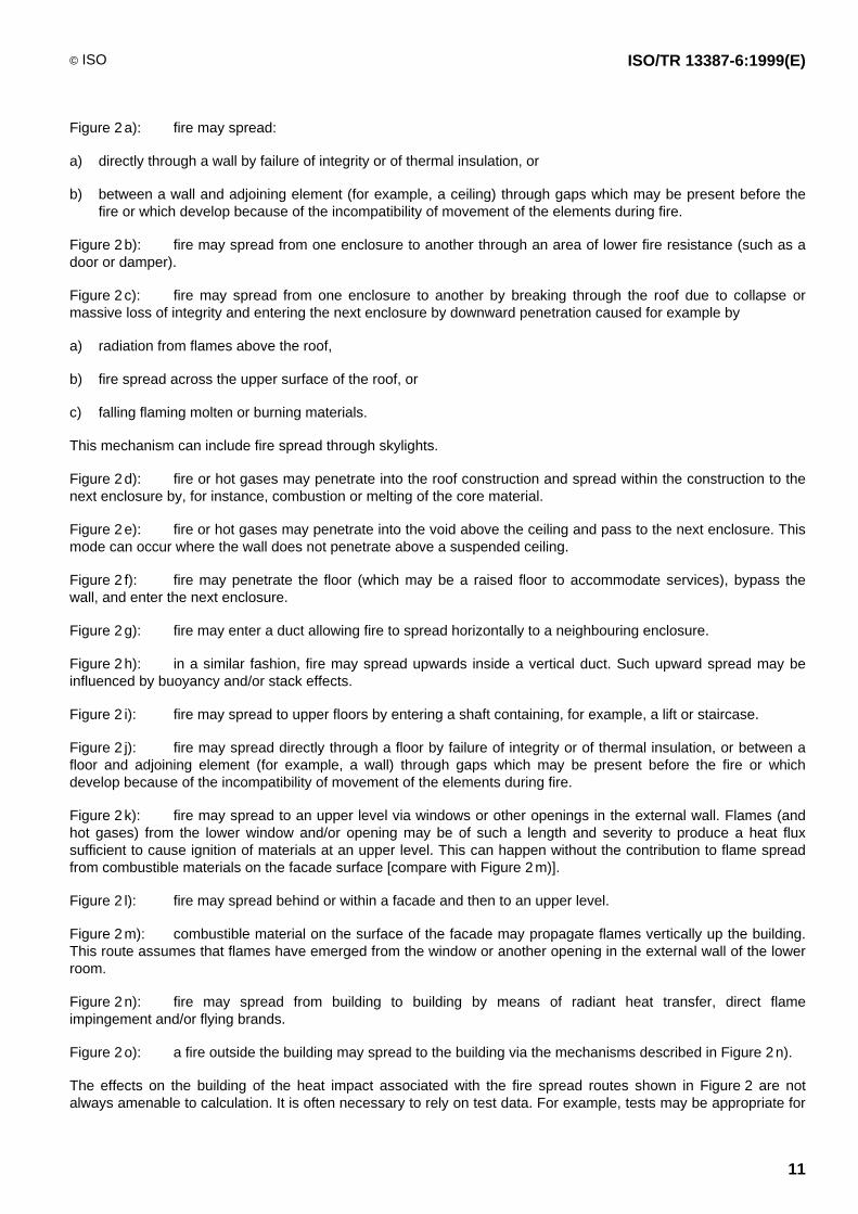
6.4.2 Fire spread routes
There may be several possible routes by which fire may spread and due attention should be paid to each.Examples of some major and frequently occurring fire spread routes are illustrated in the diagrams shown inFigure 2. The following notes relating to each of the diagrams are intended to clarify these routes and, whereappropriate, the factors affecting them. The separations depicted in Figure 2 represent real assemblies completewith service penetrations for wiring, piping, etc. These assemblies may or may not be fire-rated.

ISO/TR 13387-6:1999(E) © ISO
10
Key
1 Wall 7 Vertical duct 13 Exposed building
2 Wall opening 8 Shaft (lifts, staircases, etc.) 14 Radiation
3 Roof 9 Window 15 Exposing building
4 Void 10 Façades 16 Wind
5 Floor 11 Surface of façades 17 External fire source
6 Horizontal duct 12 Flying brands 18 Flame spread
Figure 2 — Some frequently occurring fire spread routes
© ISO ISO/TR 13387-6:1999(E)
11
Figure 2 a): fire may spread:
a) directly through a wall by failure of integrity or of thermal insulation, or
b) between a wall and adjoining element (for example, a ceiling) through gaps which may be present before thefire or which develop because of the incompatibility of movement of the elements during fire.
Figure 2 b): fire may spread from one enclosure to another through an area of lower fire resistance (such as adoor or damper).
Figure 2 c): fire may spread from one enclosure to another by breaking through the roof due to collapse ormassive loss of integrity and entering the next enclosure by downward penetration caused for example by
a) radiation from flames above the roof,
b) fire spread across the upper surface of the roof, or
c) falling flaming molten or burning materials.
This mechanism can include fire spread through skylights.
Figure 2 d): fire or hot gases may penetrate into the roof construction and spread within the construction to thenext enclosure by, for instance, combustion or melting of the core material.
Figure 2 e): fire or hot gases may penetrate into the void above the ceiling and pass to the next enclosure. Thismode can occur where the wall does not penetrate above a suspended ceiling.
Figure 2 f): fire may penetrate the floor (which may be a raised floor to accommodate services), bypass thewall, and enter the next enclosure.
Figure 2 g): fire may enter a duct allowing fire to spread horizontally to a neighbouring enclosure.
Figure 2 h): in a similar fashion, fire may spread upwards inside a vertical duct. Such upward spread may beinfluenced by buoyancy and/or stack effects.
Figure 2 i): fire may spread to upper floors by entering a shaft containing, for example, a lift or staircase.
Figure 2 j): fire may spread directly through a floor by failure of integrity or of thermal insulation, or between afloor and adjoining element (for example, a wall) through gaps which may be present before the fire or whichdevelop because of the incompatibility of movement of the elements during fire.
Figure 2 k): fire may spread to an upper level via windows or other openings in the external wall. Flames (andhot gases) from the lower window and/or opening may be of such a length and severity to produce a heat fluxsufficient to cause ignition of materials at an upper level. This can happen without the contribution to flame spreadfrom combustible materials on the facade surface [compare with Figure 2 m)].
Figure 2 l): fire may spread behind or within a facade and then to an upper level.
Figure 2 m): combustible material on the surface of the facade may propagate flames vertically up the building.This route assumes that flames have emerged from the window or another opening in the external wall of the lowerroom.
Figure 2 n): fire may spread from building to building by means of radiant heat transfer, direct flameimpingement and/or flying brands.
Figure 2 o): a fire outside the building may spread to the building via the mechanisms described in Figure 2 n).
The effects on the building of the heat impact associated with the fire spread routes shown in Figure 2 are notalways amenable to calculation. It is often necessary to rely on test data. For example, tests may be appropriate for

ISO/TR 13387-6:1999(E) © ISO
12
routes shown in Figure 2 c) through 2 j) (bypass routes), 2 l) and 2 m). The effects of the heat impact associated withroutes shown in Figure 2 a) (direct), 2 b), 2 n) and 2 o) can usually be calculated.
When using Figure 2, engineering judgement is effective in assessing different possible fire and/or smoke routes.An event tree analysis (see ISO/TR 13387-2) can help find the probabilities of failure routes in fire barriers.Statistical data from real fires are needed to estimate the different failure rates.
6.4.2.1 Fire spread (enclosure to enclosure)
Fire spread from enclosure to enclosure can occur through openings existing before the fire commences. Suchspread is more appropriately addressed by SS1.
Fire spread from enclosure to enclosure can also occur as a result of thermal insulation failure, integrity failure orstructural failure of the building element separating the two enclosures. Calculation of the thermal and mechanicalcondition of the separating element following 6.2 and 6.3 provides input data needed to make an assessment of thelikelihood of fire spread.
For example, thermal insulation failure can be considered to have occurred if the thermal analysis predicts that thetemperature on the unexposed side of the separating building element exceeds a critical temperature.
Integrity failure can be considered to have occurred if the thermal analysis predicts openings have developed in theseparating building element because of the melting of materials or the mechanical analysis predicts that openingshave developed due to the shrinkage (expansion) of materials, spalling or delamination.
Structural failure can be considered to occur if the thermal and mechanical analyses predict the separating buildingelement (or another element which supports it) is no longer able to sustain the applied actions (loads).
6.4.2.2 Fire spread (exterior routes)
Figure 2 k) and 2 m) identify routes for fire spread from floor to floor along the exterior of the building. In both cases,fire has destroyed windows and flames project through the window. Buoyancy and entrainment of air will causethese projected flames to be in contact with or, at least, in close proximity to the facade above the window.
The vertical and horizontal components of this flame projection depend upon the rate of burning within theenclosure, and the dimensions of the window. If the shape of the flames has not been determined by SS2 it can beestimated using simple correlations (see reference [5]).
A calculation of radiative and/or convective heat transfer from the projected flame to the facade together with theproperties of the facade will determine whether it will ignite and spread flame vertically to the next storey.
A calculation of radiative and/or convective heat transfer from the projected flame to (through) the window on thenext storey will determine whether fire can break into the next storey even if the facade is not combustible.
It should be noted that exterior steel columns which form part of the structure of the building can also be heated bydirect flame impingement or by radiation. An engineering analysis of heat transfer to these columns can beundertaken in a fashion similar to that for the facade itself.
6.4.2.3 Fire spread (building to building)
Figure 2 n) identifies routes for fire spread from building to building. Fire may penetrate the external wall of abuilding as a result of the failure of the glazing or burn-through of areas of low fire resistance. The amount ofemitted radiation may be sufficient to cause piloted ignition (with the assistance of flying brands) or spontaneousignition of materials on the outside or inside of an exposed building nearby. Fire spread between buildings in thisway can be modelled from a knowledge of the emitted radiation intensity, the configuration factor and the ignitabilityof materials exposed on the neighbouring building (see reference [6]).
There is little technical guidance available on the spread of fire by flying brands in the absence of radiation. The sizeof brands generated depends upon the size of the fire in the burning building. It is likely that small brands go out(extinguish) while “flying” and large brands fall to the ground before “flying” far. This means the greatest danger is

© ISO ISO/TR 13387-6:1999(E)
13
from medium brands which may “fly” some distance while still burning. The risk of ignition of combustible materialson a neighbouring building can be assessed based on:
the size of the brands;
the trajectory of the brands; and
local cooling conditions.
7 Engineering methods
7.1 General
A number of practical engineering methods (see reference [7]) have been developed to predict the thermal andmechanical response of building elements exposed to fire and hence to assess the potential for fire spread withinand between buildings, and to predict the response of structures exposed to fire. The purpose of this clause is togive general guidance on the selection, use and limitations of engineering methods. The types of methodsconsidered below include estimation formulae, computer models and experimental methods.
If a mathematical model (estimation formula or computer model) is selected for an application, it should beassessed and verified using the principles documented in ISO/TR 13387-3. This should aid in evaluating thelimitations of the model. Furthermore, special care should be taken when using input data published in the literature.The quantitative information may be related to specific test conditions and/or specific commercial products, and theapplication of the data under different conditions may result in significant errors.
7.2 Estimation formulae
Estimation formulae (or hand calculations) are often derived from an analysis of highly simplified physical situationsor are empirical correlations based on experience or test data. They can be used to check the results of computercalculations, for preliminary calculations, or if detailed computer calculations are unnecessary or unavailable.
Estimation formulae for predicting fire spread between enclosures are generally based on the standard fireresistance test ISO 834-1, and are therefore only applicable to conditions similar to those in the test. Thecomponent additive calculation procedure for assessing the performance of wood-frame assemblies is a typicalexample (see reference [8]).
The shape of a flame projecting through a window can be estimated by hand calculation (see reference [5]). Acalculation of radiative heat transfer from the projected flame to the window on the next storey will determinewhether fire can break into the next storey.
The potential for fire spread from building to building due to radiant heat transfer is also amenable to handcalculation. The potential for fire spread can be calculated from knowledge of the emitted radiation intensity, theconfiguration factor and the ignitability of materials exposed on the neighbouring building (see reference [6]).
7.3 Computer models
Computer models which predict the thermal and mechanical response of building elements exposed to fire aresimply mathematical representations of the physical and chemical behaviour that constitute fire processes. Some ofthe most important factors governing the predictive capabilities of computer models include the level of theassumptions and simplifications of the physical and chemical processes that constitute the models and the data thatmust be input at the start of the calculations. As a general rule, a thermal model is first run to calculate thetemperature-time profile within elements. This output from the thermal model becomes input for the mechanicalmodel.
The governing heat transfer and solid mechanics equations that form the basis of these computer models typicallyrequire a numerical solution using either finite element or finite difference methods. Finite difference methods areused in problems with simple geometry and reasonably homogeneous materials. For more complex geometries andfor heterogeneous materials, finite element methods are advisable.

ISO/TR 13387-6:1999(E) © ISO
14
A more detailed discussion of computer models which predict the thermal and mechanical response of buildingelements is found in ISO/TR 10158 and in the literature (see reference [7]).
7.4 Experimental methods
Over the years, the fire-resistance ratings of many building elements have been determined by subjectingspecimens to the standard fire resistance test ISO 834-1. Listings of fire-resistance ratings are useful whendemonstrating compliance with prescriptive regulations. Such data may also be useful for fire safety engineeringanalyses. For example, the fire performance of building elements in real fires can be inferred from knowledge oftheir fire-resistance rating together with a model for representing a post-flashover fire as a standard fire of"equivalent" duration (see ISO/TR 13387-2). This approach can be particularly useful for building elements for whichestimation formulae and computer models are not available. For example, detailed computer simulation of theperformance of dampers exposed to fire requires modelling both 3-D heat transfer and the deflection of blades, andis beyond the capability of current models.
Other practical information has been derived by subjecting building elements to the standard test ISO 834-1. Forinstance, thermophysical property data can be inferred from thermal resistance data measured during fire tests. Forsome products, such data may be the best high temperature data available for the use in fire models.
Care should, however, be exercised when applying the results of a fire resistance test to a construction which islarger than the test specimen. An example is a specimen which is susceptible to thermal bowing at elevatedtemperatures. Thermal bowing of a specimen 3 m high may have negligible effect on the structural stability of thespecimen in a furnace test. In a similar construction two or three times higher (i.e., 6 m or 9 m high), thermal bowingis a factor of four or nine times greater, respectively. This greater thermal bowing can lead to instability especially intall fire walls in single-storey buildings which can be 30 m high. Guidance for the application and extension of fireresistance test results is provided in ISO 12470.
For some applications it may be desirable to design an ad hoc test to assess the thermal and mechanical responseof separating or load-bearing elements. Whether the scenario of interest involves a localized fire or a post-flashoverenclosure fire, every effort should be taken to ensure the thermal exposure in the ad hoc test is representative ofthat expected in the actual facility. For a post-flashover fire, the fire load, physical scaling, thermal properties ofsurface finish and ventilation conditions should replicate those in the facility of interest. Guidance for conducting adhoc enclosure fire experiments is provided in references [9] and [10].
8 Guidance for setting criteria
Care must be taken in selecting acceptance or failure criteria. Such criteria may be quite different for fire safetyengineering design than for design employing prescriptive regulations.
For example, fire resistance is an important property affecting fire spread and is often referred to in nationalregulations. Fire resistance criteria are concerned with thermal insulation, integrity and load-bearing capacity(stability). These criteria may need to be reconsidered in a fire safety engineering assessment. The thermalinsulation and integrity criteria for an external wall attacked by fire from inside the building can be relaxed makingthem less onerous depending upon the fire risk near the external wall. For instance, if the external wall is acting as aflame shield (in order to prevent radiation emitted from the external wall from causing ignition of a nearby building) itmay be onerous and unnecessary to adopt the traditional fire-resistance thermal insulation criterion which requiresthat the unexposed face of the construction should not experience a temperature rise of more than 180 °C at anypoint: a higher temperature can be accepted if radiation is the primary consideration. Again, it may be onerous toapply the standard integrity criterion chosen to prevent ignition of stored goods in contact with or very close to theunexposed face if the external wall is spaced away from buildings nearby. In such cases the size of holes (ortemperature of the unexposed surface) which can be tolerated could be calculated from a knowledge of theacceptable level of radiation intensity incident on the exposed risk, the configuration factor and the level of emittedradiation intensity.
It is common to express the thermal insulation criterion for a separating building element in terms of a temperaturerise on the unexposed side of the element. In fire safety engineering calculations, the criterion in ISO 834-1 may beconsidered to be too stringent. Instead, the ignition of materials in contact with or even some distance from theexposed side of the element, which may occur when they reach their piloted-ignition temperature, can be adopted

© ISO ISO/TR 13387-6:1999(E)
15
as the measure of excessive heat transmission. On the other hand, for some applications, the criterion in ISO 834-1may not be considered sufficiently stringent. For example, if the separating wall is intended to protect magnetictapes from excessive heat transmission, a temperature rise criterion well below that employed in ISO 834-1 mayhave to be selected.
In prescriptive building regulations, the criterion to prevent fire spread from building to building by radiation is oftenexpressed implicitly in terms of heat flux. For example, there may be a requirement for combustible materials on thefacade of the exposed building not to experience a heat flux greater than the critical radiant heat flux for the ignitionof wood. In fire safety engineering calculations, this criterion may be considered to be too stringent. If, for example,superlative firefighting capabilities are at hand or if the facade has much better ignition resistance than wood, amoderately higher heat flux at the facade of the exposed building may be acceptable.
For fire safety engineering calculations, the structural failure criteria in ISO 834-1 may not be considered reliable,but should instead be tailored for a given application. Such criteria can be expressed in terms of a criticaltemperature rise, load-bearing capacity, thermal expansion or excessive deflection. The deflection criterion, inparticular, needs to be carefully selected for large-span flexural elements. It is important to recognize that, what isregarded as structural failure or limit of deflection in the fire resistance test, can be significantly different in realstructures. In this context, the interaction of large beam deflections on the stability and/or integrity of compartmentwalls must be considered as an integral part of the analysis.
Finally, criteria for fire spread from storey to storey can be expressed in terms of one or more of the following:
a critical heat flux though the upper storey window (with or without glass) which prevents ignition ofcombustibles;
a critical temperature which prevents breakage of the window on the upper storey;
a critical flame length which prevents exposure of the upper window; and
a critical heat flux which prevents flame spread on the facade.

ISO/TR 13387-6:1999(E) © ISO
16
Bibliography
[1] TIEN C.L., LEE K.Y. and STRETTON A.J. Radiation Heat Transfer. In: SFPE Handbook of Fire ProtectionEngineering, National Fire Protection Association, Quincy, U.S.A., 2nd ed., 1995, Chapters 1-4.
[2] ATREYA A. Convection Heat Transfer. In: SFPE Handbook of Fire Protection Engineering, National FireProtection Association, Quincy, U.S.A., 2nd ed., 1995, Chapters 1-3.
[3] ROCKETT J.A. and MILKE J.A. Conduction of Heat in Solids. In: SFPE Handbook of Fire Protection Engineering,National Fire Protection Association, Quincy, U.S.A., 2nd ed., 1995, Chapters 1-2.
[4] FITZGERALD R.W. Structural Mechanics. In: SFPE Handbook of Fire Protection Engineering, National FireProtection Association, Quincy, U.S.A., 2nd ed., 1995, Chapters 1-8.
[5] DRYSDALE D. An Introduction to Fire Dynamics. J. Wiley and Sons. 1985, p. 347.
[6] DRYSDALE D. An Introduction to Fire Dynamics. J. Wiley and Sons. 1985, p. 65.
[7] SULLIVAN P.J.E., TERRO M.J. and MORRIS W.A. Critical Review of Fire-Dedicated Thermal and StructuralComputer Programs, Journal of Applied Fire Science, 3, 1993-1994, pp. 113-135.
[8] WHITE R.H. Analytical Methods for Determining Fire Resistance of Timber Members. In: SFPE Handbook ofFire Protection Engineering, National Fire Protection Association, Quincy, U.S.A., 2nd ed., 1995,Chapters 4-11.
[9] ASTM E603-98, Standard Guide for Room Fire Experiments. West Conshohocken, PA, 1999.
[10] BS 476-32:1989, Fire tests on building materials and structures. Guide to full scale fire tests within buildings.BSI Standards, London, 1989, 14 p.
General
[11] SFPE Handbook of Fire Protection Engineering, National Fire Protection Association, Quincy, U.S.A., 2nd ed.,1995.
[12] PURKISS, Fire Safety Engineering Design of Structures, Butterworth-Heinemann, Oxford, 1996.
[13] HARMATHY, Design to Cope with Fully Developed Fires. In: ASTM STP 685 Design of Buildings for Fire Safety,ASTM, Philadelphia, 1979, pp. 198-276.
[14] Structural Fire Protection. ASCE Manuals and Reports on Engineering Practice. (LIE T.T. ed.) America Societyof Civil Engineers, New York, 78, 1992.
[15] ENV 1991-2-2:1995, Eurocode 1 — Basis of design and actions on structures — Part 2-2: Actions onstructures — Actions on structures exposed to fire.
Spatial separations
[16] BARNETT, Separation between External Walls of Buildings. Proceedings of the Second International Symposiumon Fire Safety Science. Hemisphere. 1989.

© ISO ISO/TR 13387-6:1999(E)
17
Flame projection through windows
[17] ENV 1991-2-2:1995, Eurocode 1 — Basis of design and actions on structures — Part 2.2: Actions onstructures — Actions on structures exposed to fire, Annex C.
[18] LAW and O'BRIEN T. Fire Safety of Bare External Structural Steel, SCI Publication 009, The Steel ConstructionInstitute, UK, 1989.

ISO/TR 13387-6:1999(E) © ISO
ICS 13.220.01
Price based on 17 pages


![NCI Experimental Therapeutics Clinical Trials Network (ETCTN) … - Ivy.pdf · 2017. 11. 21. · IDO . 1 -Methyl [D] tryptophan . Hsp90 . AT 13387 PU-H71 . Proteasome . bortezomib](https://img.pdfslide.net/doc/110x75/5fe703767a32000c2d52f0ec/nci-experimental-therapeutics-clinical-trials-network-etctn-ivypdf-2017.jpg)