Embed Size (px)
Citation preview

1364 N. Watkins Package 1 - Renovations
Project Manual Construction Documents
May 14, 2021
Memphis Area Transit Authority 1370 Levee Road Memphis, TN 38108
Architects brg3sarchitects 396 N Cleveland St Memphis, TN 38104 901 260 9600
Mechanical & Electrical Engineers SSR 2560 Thousand Oaks Boulevard, Suite 3200 Memphis, TN 38118 901 683 3990


Memphis Area Transit Authority 1364 N WatkinsPackage 1 - Renovations
2020698 00 0107 Page 1 of 2
SECTION 00 0107SEALS PAGE
ARCHITECTURE
END OF SEALS PAGE

Memphis Area Transit Authority 1364 N WatkinsPackage 1 - Renovations
2020698 00 0107 Page 2 of 2
Memphis Area Transit Authority1364 N WatkinsPackage 1 - Renovations
2020698 00 0110 Page 1 of 2
SECTION 00 0110TABLE OF CONTENTS
PROCUREMENT AND CONTRACTING REQUIREMENTS1.01 DIVISION 00 -- PROCUREMENT AND CONTRACTING REQUIREMENTS
A. 00 0107 - Seals PageB. 00 0110 - Table of ContentsC. 00 4323 - Alternates Form
SPECIFICATIONS2.01 DIVISION 01 -- GENERAL REQUIREMENTS
A. 01 1000 - SummaryB. 01 2000 - Price and Payment ProceduresC. 01 2300 - AlternatesD. 01 2500 - Substitution ProceduresE. 01 3000 - Administrative RequirementsF. 01 3216 - Construction Progress ScheduleG. 01 4000 - Quality RequirementsH. 01 5000 - Temporary Facilities and ControlsI. 01 6000 - Product RequirementsJ. 01 6116 - Volatile Organic Compound (VOC) Content Restrictions
1. 01 6116.01 - Accessory Material VOC Content Certification FormK. 01 7000 - Execution and Closeout RequirementsL. 01 7800 - Closeout Submittals
2.02 DIVISION 02 -- EXISTING CONDITIONS A. 02 4100 - Demolition
2.03 DIVISION 03 -- CONCRETE A. 03 5400 - Cast Underlayment
2.04 DIVISION 04 -- MASONRY A. 04 2900 - Engineered Unit Masonry
2.05 DIVISION 05 -- METALS A. 05 5000 - Metal Fabrications
2.06 DIVISION 06 -- WOOD, PLASTICS, AND COMPOSITES A. 06 1000 - Rough CarpentryB. 06 2000 - Finish CarpentryC. 06 4100 - Architectural Wood Casework
2.07 DIVISION 07 -- THERMAL AND MOISTURE PROTECTION A. 07 8400 - FirestoppingB. 07 9200 - Joint Sealants
2.08 DIVISION 08 -- OPENINGS A. 08 1213 - Hollow Metal FramesB. 08 1416 - Flush Wood DoorsC. 08 4313 - Aluminum-Framed Storefronts

Memphis Area Transit Authority1364 N WatkinsPackage 1 - Renovations
2020698 00 0110 Page 2 of 2
D. 08 7100 - Door HardwareE. 08 8000 - Glazing
2.09 DIVISION 09 -- FINISHES A. 09 2116 - Gypsum Board AssembliesB. 09 3000 - TilingC. 09 5100 - Acoustical CeilingsD. 09 6500 - Resilient FlooringE. 09 9113 - Exterior PaintingF. 09 9123 - Interior Painting
2.10 DIVISION 10 -- SPECIALTIES A. 10 2800 - Toilet, Bath, and Laundry AccessoriesB. 10 4400 - Fire Protection Specialties
2.11 DIVISION 11 -- EQUIPMENT 2.12 DIVISION 12 -- FURNISHINGS
A. 12 3600 - Countertops2.13 DIVISION 13 -- SPECIAL CONSTRUCTION 2.14 DIVISION 14 -- CONVEYING EQUIPMENT 2.15 DIVISION 21 -- FIRE SUPPRESSION 2.16 DIVISION 22 -- PLUMBING 2.17 DIVISION 23 -- HEATING, VENTILATING, AND AIR-CONDITIONING (HVAC) 2.18 DIVISION 25 -- INTEGRATED AUTOMATION 2.19 DIVISION 26 -- ELECTRICAL 2.20 DIVISION 27 -- COMMUNICATIONS 2.21 DIVISION 28 -- ELECTRONIC SAFETY AND SECURITY 2.22 DIVISION 31 -- EARTHWORK 2.23 DIVISION 32 -- EXTERIOR IMPROVEMENTS 2.24 DIVISION 33 -- UTILITIES 2.25 DIVISION 34 -- TRANSPORTATION 2.26 DIVISION 40 -- PROCESS INTEGRATION 2.27 DIVISION 46 -- WATER AND WASTEWATER EQUIPMENT
END OF SECTION
Memphis Area Transit Authority 1364 N WatkinsPackage 1 - Renovations
2020698 00 4323 Page 1 of 2
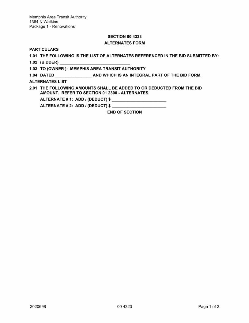
SECTION 00 4323ALTERNATES FORM
PARTICULARS1.01 THE FOLLOWING IS THE LIST OF ALTERNATES REFERENCED IN THE BID SUBMITTED BY:1.02 (BIDDER) _______________________________1.03 TO (OWNER ): MEMPHIS AREA TRANSIT AUTHORITY1.04 DATED ________________ AND WHICH IS AN INTEGRAL PART OF THE BID FORM.ALTERNATES LIST2.01 THE FOLLOWING AMOUNTS SHALL BE ADDED TO OR DEDUCTED FROM THE BID
AMOUNT. REFER TO SECTION 01 2300 - ALTERNATES.ALTERNATE # 1: ADD / (DEDUCT) $ ________________________ALTERNATE # 2: ADD / (DEDUCT) $ ________________________
END OF SECTION

Memphis Area Transit Authority 1364 N WatkinsPackage 1 - Renovations
2020698 00 4323 Page 2 of 2
Memphis Area Transit Authority1364 N WatkinsPackage 1 - Renovations
2020698 01 1000 Page 1 of 2
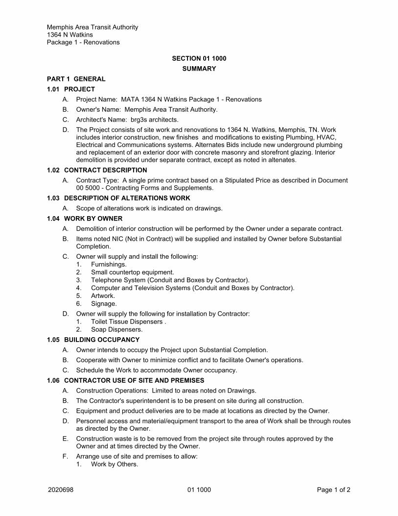
SECTION 01 1000SUMMARY
PART 1 GENERAL1.01 PROJECT
A. Project Name: MATA 1364 N Watkins Package 1 - RenovationsB. Owner's Name: Memphis Area Transit Authority.C. Architect's Name: brg3s architects.D. The Project consists of site work and renovations to 1364 N. Watkins, Memphis, TN. Work
includes interior construction, new finishes and modifications to existing Plumbing, HVAC,Electrical and Communications systems. Alternates Bids include new underground plumbingand replacement of an exterior door with concrete masonry and storefront glazing. Interiordemolition is provided under separate contract, except as noted in altenates.
1.02 CONTRACT DESCRIPTIONA. Contract Type: A single prime contract based on a Stipulated Price as described in Document
00 5000 - Contracting Forms and Supplements.1.03 DESCRIPTION OF ALTERATIONS WORK
A. Scope of alterations work is indicated on drawings.1.04 WORK BY OWNER
A. Demolition of interior construction will be performed by the Owner under a separate contract.B. Items noted NIC (Not in Contract) will be supplied and installed by Owner before Substantial
Completion. C. Owner will supply and install the following:
1. Furnishings.2. Small countertop equipment.3. Telephone System (Conduit and Boxes by Contractor).4. Computer and Television Systems (Conduit and Boxes by Contractor).5. Artwork.6. Signage.
D. Owner will supply the following for installation by Contractor:1. Toilet Tissue Dispensers .2. Soap Dispensers.
1.05 BUILDING OCCUPANCYA. Owner intends to occupy the Project upon Substantial Completion.B. Cooperate with Owner to minimize conflict and to facilitate Owner's operations.C. Schedule the Work to accommodate Owner occupancy.
1.06 CONTRACTOR USE OF SITE AND PREMISESA. Construction Operations: Limited to areas noted on Drawings.B. The Contractor's superintendent is to be present on site during all construction.C. Equipment and product deliveries are to be made at locations as directed by the Owner.D. Personnel access and material/equipment transport to the area of Work shall be through routes
as directed by the Owner.E. Construction waste is to be removed from the project site through routes approved by the
Owner and at times directed by the Owner.F. Arrange use of site and premises to allow:
1. Work by Others.

Memphis Area Transit Authority1364 N WatkinsPackage 1 - Renovations
2020698 01 1000 Page 2 of 2
2. Work by Owner.3. Use of site and premises by the public.
G. Provide access to and from site as required by law and by Owner:H. Interim Life Safety Measures: Contractor shall institute Life Safety measures as needed to
maintain a safe, functional and effective environment for the building occupant's life safetyduring construction activities.1. Contractor shall institute Life Safety measures as needed to maintain a safe, functional
and effective environment for the building occupant's life safety during constructionactivities.
2. The Contractor shall take action as required to implement the Interim Life SafetyMeasures.
I. Emergency Building Exits During Construction: Keep all exits required by code open duringconstruction period; provide temporary exit signs if exit routes are temporarily altered.
J. Existing building spaces may not be used for storage.K. Utility Outages and Shutdown:
1. Disruptions of utilities are to be coordinated with the Owner and scheduled a minimum of72 hours in advance. Utility outages and shutdowns are to be minimized.
2. Do not disrupt or shut down life safety systems, including but not limited to fire protectionsprinklers and fire alarm system, without 7 days notice to Owner and authorities havingjurisdiction.
1.07 WORK SEQUENCEA. Sequence work to allow for the Owner's continuous use of areas adjacent to the work.B. See drawings for additional information.C. Coordinate construction schedule and operations with Owner.
PART 2 PRODUCTS - NOT USEDPART 3 EXECUTION - NOT USED
END OF SECTION
Memphis Area Transit Authority1364 N WatkinsPackage 1 - Renovations
2020698 01 2000 Page 1 of 4
SECTION 01 2000PRICE AND PAYMENT PROCEDURES
PART 1 GENERAL1.01 SECTION INCLUDES
A. Procedures for preparation and submittal of applications for progress payments.B. Documentation of changes in Contract Sum and Contract Time.C. Change procedures.D. Correlation of Contractor submittals based on changes.E. Procedures for preparation and submittal of application for final payment.
1.02 RELATED REQUIREMENTSA. Section 00 5000 - Contracting Forms and Supplements: Forms to be used.
1.03 SCHEDULE OF VALUESA. Use Schedule of Values Form: AIA G703, edition stipulated in the Agreement.B. Electronic media printout including equivalent information will be considered in lieu of standard
form specified; submit draft to Architect for approval.C. Forms filled out by hand will not be accepted.D. Submit Schedule of Values in duplicate within 15 days after date of Owner-Contractor
Agreement.E. Format: Utilize the Table of Contents of this Project Manual. Identify each line item with
number and title of the specification Section. Identify site mobilization. Include quantities,material unit cost, material cost, labor unit cost, labor cost, total unit cost and total cost.
F. Include separately from each line item, a direct proportional amount of Contractor's overheadand profit.
G. Revise schedule to list approved Change Orders, with each Application For Payment.1.04 APPLICATIONS FOR PROGRESS PAYMENTS
A. Payment Period: Submit at intervals stipulated in the Agreement.B. Use Form AIA G702 and Form AIA G703, edition stipulated in the Agreement.C. Electronic media printout including equivalent information will be considered in lieu of standard
form specified; submit sample to Architect for approval.D. Forms filled out by hand will not be accepted.E. For each item, provide a column for listing each of the following:
1. Item Number.2. Description of work.3. Scheduled Values.4. Previous Applications.5. Work in Place and Stored Materials under this Application.6. Authorized Change Orders.7. Total Completed and Stored to Date of Application.8. Percentage of Completion.9. Balance to Finish.10. Retainage.
F. Execute certification by signature of authorized officer.G. Use data from approved Schedule of Values. Provide dollar value in each column for each line
item for portion of work performed and for stored products.

Memphis Area Transit Authority1364 N WatkinsPackage 1 - Renovations
2020698 01 2000 Page 2 of 4
H. List each authorized Change Order as a separate line item, listing Change Order number anddollar amount as for an original item of work.
I. Submit one electronic and three hard-copies of each Application for Payment.J. Include the following with the application:
1. Transmittal letter as specified for submittals in Section 01 3000.2. Construction progress schedule, revised and current as specified in Section 01 3000.3. Current construction photographs specified in Section 01 3000.4. Partial release of liens from major subcontractors and vendors.5. Project record documents as specified in Section 01 7800, for review by Owner which will
be returned to the Contractor.6. Affidavits attesting to off-site stored products.
K. When Architect requires substantiating information, submit data justifying dollar amounts inquestion. Provide one copy of data with cover letter for each copy of submittal. Showapplication number and date, and line item by number and description.
1.05 MODIFICATION PROCEDURESA. Submit name of the individual authorized to receive change documents and who will be
responsible for informing others in Contractor's employ or subcontractors of changes to Contract Documents.
B. For minor changes not involving an adjustment to the Contract Sum or Contract Time, Architectwill issue instructions directly to Contractor.
C. For other required changes, Architect will issue a document signed by Owner instructingContractor to proceed with the change, for subsequent inclusion in a Change Order.1. The document will describe the required changes and will designate method of
determining any change in Contract Sum or Contract Time.2. Promptly execute the change.
D. For changes for which advance pricing is desired, Architect will issue a document that includesa detailed description of a proposed change with supplementary or revised drawings andspecifications, a change in Contract Time for executing the change . Contractor shall prepareand submit a fixed price quotation within 14 days.
E. Contractor may propose a change by submitting a request for change to Architect, describingthe proposed change and its full effect on the work, with a statement describing the reason forthe change, and the effect on the Contract Sum and Contract Time with full documentation. Document any requested substitutions in accordance with Section 01 6000.
F. Computation of Change in Contract Amount: As specified in the Agreement and Conditions ofthe Contract.1. For change requested by Architect for work falling under a fixed price contract, the amount
will be based on Contractor's price quotation.2. For change requested by Contractor, the amount will be based on the Contractor's
request for a Change Order as approved by Architect.3. For pre-determined unit prices and quantities, the amount will based on the fixed unit
prices.4. For change ordered by Architect without a quotation from Contractor, the amount will be
determined by Architect based on the Contractor's substantiation of costs as specified forTime and Material work.
G. Substantiation of Costs: Provide full information required for evaluation.1. On request, provide the following data:
a. Quantities of products, labor, and equipment.b. Taxes, insurance, and bonds.c. Overhead and profit.d. Justification for any change in Contract Time.

Memphis Area Transit Authority1364 N WatkinsPackage 1 - Renovations
2020698 01 2000 Page 3 of 4
e. Credit for deletions from Contract, similarly documented.2. Support each claim for additional costs with additional information:
a. Origin and date of claim.b. Dates and times work was performed, and by whom.c. Time records and wage rates paid.d. Invoices and receipts for products, equipment, and subcontracts, similarly
documented.3. For Time and Material work, submit itemized account and supporting data after
completion of change, within time limits indicated in the Conditions of the Contract.H. Execution of Change Orders: Architect will issue Change Orders for signatures of parties as
provided in the Conditions of the Contract.I. After execution of Change Order, promptly revise Schedule of Values and Application for
Payment forms to record each authorized Change Order as a separate line item and adjust theContract Sum.
J. Promptly revise progress schedules to reflect any change in Contract Time, revisesub-schedules to adjust times for other items of work affected by the change, and resubmit.
K. Promptly enter changes in Project Record Documents.1.06 APPLICATION FOR FINAL PAYMENT
A. Prepare Application for Final Payment as specified for progress payments, identifying totaladjusted Contract Sum, previous payments, and sum remaining due.
B. Application for Final Payment will not be considered until the following have beenaccomplished:1. All closeout procedures specified in Section 01 7000.
PART 2 PRODUCTS - NOT USEDPART 3 EXECUTION - NOT USED
END OF SECTION

Memphis Area Transit Authority1364 N WatkinsPackage 1 - Renovations
2020698 01 2000 Page 4 of 4

Memphis Area Transit Authority1364 N WatkinsPackage 1 - Renovations
2020698 01 2300 Page 1 of 2
SECTION 01 2300ALTERNATES
PART 1 GENERAL1.01 SECTION INCLUDES
A. Description of Alternates.B. Procedures for pricing Alternates.C. Documentation of changes to Contract Price and Contract Time.
1.02 ACCEPTANCE OF ALTERNATESA. Alternates quoted on Bid Forms will be reviewed and accepted or rejected at Owner's option.
Accepted Alternates will be identified in the Owner-Contractor Agreement.B. Coordinate related work and modify surrounding work to integrate the Work of each Alternate.
1.03 SCHEDULE OF ALTERNATESA. Alternate No. 1 - Underground Plumbing:
1. Base Bid Item: Concrete slab demolition and underground plumbing for new work is notincluded in the Base Bid.
2. Alternate Bid: Concrete floor slab demolition, underground plumbing and patchingconcrete floor slab; see drawing P121.
B. Alternate No. 2 - Replacement of Exterior Door with New Window Unit (Storefront Glazing):1. Base Bid: Existing exterior doors to remain in place.2. Alternate Bid: Remove existing exterior door as indicated on drawings and provide new
infill construction consisting of concrete masonry and storefront glazing. Provide newgypsum board finish on interior to match existing construction. Seal storefront framing inopening and paint new concrete block on exterior to match existing.
PART 2 PRODUCTS - NOT USEDPART 3 EXECUTION - NOT USED
END OF SECTION

Memphis Area Transit Authority1364 N WatkinsPackage 1 - Renovations
2020698 01 2300 Page 2 of 2

Memphis Area Transit Authority1364 N WatkinsPackage 1 - Renovations
2020698 01 2500 Page 1 of 4
SECTION 01 2500SUBSTITUTION PROCEDURES
PART 1 GENERAL1.01 SECTION INCLUDES
A. Procedural requirements for proposed substitutions.1.02 RELATED REQUIREMENTS
A. Section 01 3000 - Administrative Requirements: Submittal procedures, coordination.B. Section 01 6000 - PRODUCT REQUIREMENTS: Fundamental product requirements, product
options, delivery, storage, and handling.C. Section 01 6116 - Volatile Organic Compound (VOC) Content Restrictions: Restrictions on
emissions of indoor substitute products.1.03 DEFINITIONS
A. Substitutions: Changes from Contract Documents requirements proposed by Contractor tomaterials, products, assemblies, and equipment.1. Substitutions for Cause: Proposed due to changed Project circumstances beyond
Contractor's control.a. Unavailability.b. Regulatory changes.
2. Substitutions for Convenience: Proposed due to possibility of offering substantialadvantage to the Project.
1.04 REFERENCE STANDARDSA. CSI/CSC Form 1.5C - Substitution Request (During the Bidding/Negotiating Stage); Current
Edition.B. CSI/CSC Form 13.1A - Substitution Request (After the Bidding/Negotiating Phase); Current
Edition.PART 2 PRODUCTS - NOT USEDPART 3 EXECUTION3.01 GENERAL REQUIREMENTS
A. A Substitution Request for products, assemblies, materials, and equipment constitutes arepresentation that the submitter:1. Has investigated proposed product and determined that it meets or exceeds the quality
level of the specified product, equipment, assembly, or system.2. Agrees to provide the same warranty for the substitution as for the specified product.3. Agrees to provide same or equivalent maintenance service and source of replacement
parts, as applicable.4. Agrees to coordinate installation and make changes to other work that may be required for
the work to be complete, with no additional cost to Owner.5. Waives claims for additional costs or time extension that may subsequently become
apparent.6. Agrees to reimburse Owner and Architect for review or redesign services associated with
re-approval by authorities.B. Document each request with complete data substantiating compliance of proposed substitution
with Contract Documents. Burden of proof is on proposer.1. Note explicitly any non-compliant characteristics.
C. Content: Include information necessary for tracking the status of each Substitution Request,and information necessary to provide an actionable response.1. Forms indicated in the Project Manual are adequate for this purpose, and must be used.

Memphis Area Transit Authority1364 N WatkinsPackage 1 - Renovations
2020698 01 2500 Page 2 of 4
D. Limit each request to a single proposed substitution item.1. Submit an electronic document, combining the request form with supporting data into
single document.3.02 SUBSTITUTION PROCEDURES DURING PROCUREMENT
A. Submittal Time Restrictions:1. Owner will consider requests for substitutions only if submitted at least 10 days prior to the
date for receipt of bids.B. Products Specified by Naming One or More Manufacturers with a Provision for Substitutions:
Submit a request for substitution for any manufacturer not named.1. After the Contract has been executed, the Owner and the Architect will consider a formal
request for substitution of products specified by Trade Name under the conditions listedhere within. The specifications are intended to be open to equal products except where nosubstitution is indicated. The specification shall be accessible to any reputablemanufacturer (except where noted otherwise) whose product, in the Architects opinion, isequal to that named or described and meets the requirements of the Contract Documents.
2. The Architect shall be the sole judge of products submitted as being equal to thosespecified in respect to comparative qualities, and his decision shall be final andconclusive.
C. Submittal Form (before award of contract):1. Submit substitution requests by completing CSI/CSC Form 1.5C - Substitution Request.
See this form for additional information and instructions. Use only this form; other formsof submission are unacceptable.
3.03 SUBSTITUTION PROCEDURES DURING CONSTRUCTIONA. Submittal Form (after award of contract):
1. Submit substitution requests by completing CSI/CSC Form 13.1A - Substitution Request(After Bidding/Negotiating). See this form for additional information and instructions. Useonly this form; other forms of submission are unacceptable.
B. Architect will consider requests for substitutions only within 30 days after date of Agreement.C. Submit request for Substitution for Cause within 14 days of discovery of need for substitution,
but not later than 14 days prior to time required for review and approval by Architect, in order tostay on approved project schedule.
D. Submit request for Substitution for Convenience immediately upon discovery of its potentialadvantage to the project, but not later than 14 days prior to time required for review andapproval by Architect, in order to stay on approved project schedule.1. In addition to meeting general documentation requirements, document how the requested
substitution benefits the Owner through cost savings, time savings, greater energyconservation, or in other specific ways.
2. Document means of coordinating of substitution item with other portions of the work,including work by affected subcontractors.
3. Bear the costs engendered by proposed substitution of:a. Owner's compensation to the Architect for any required redesign, time spent
processing and evaluating the request.b. Other unanticipated project considerations.
E. Substitutions will not be considered under one or more of the following circumstances:1. When they are indicated or implied on shop drawing or product data submittals, without
having received prior approval.2. Without a separate written request.3. When acceptance will require revisions to Contract Documents.

Memphis Area Transit Authority1364 N WatkinsPackage 1 - Renovations
2020698 01 2500 Page 3 of 4
3.04 RESOLUTIONA. Architect may request additional information and documentation prior to rendering a decision.
Provide this data in an expeditious manner.B. Architect will notify Contractor in writing of decision to accept or reject request.
1. Architect's decision following review of proposed substitution will be noted on thesubmitted form.
3.05 ACCEPTANCEA. Accepted substitutions change the work of the Project. They will be documented and
incorporated into work of the project by Change Order, Construction Change Directive,Architectural Supplementary Instructions, or similar instruments provided for in the Conditionsof the Contract.
3.06 CLOSEOUT ACTIVITIESA. See Section 01 7800 - Closeout Submittals, for closeout submittals.B. Include completed Substitution Request Forms as part of the Project record. Include both
approved and rejected Requests.END OF SECTION

Memphis Area Transit Authority1364 N WatkinsPackage 1 - Renovations
2020698 01 2500 Page 4 of 4
Memphis Area Transit Authority1364 N WatkinsPackage 1 - Renovations
2020698 01 3000 Page 1 of 10
SECTION 01 3000ADMINISTRATIVE REQUIREMENTS
PART 1 GENERAL1.01 SECTION INCLUDES
A. General administrative requirements.B. Electronic document submittal service.C. Preconstruction meeting.D. Site mobilization meeting.E. Progress meetings.F. Construction progress schedule.G. Progress photographs.H. Submittals for review, information, and project closeout.I. Number of copies of submittals.J. Requests for Interpretation (RFI) procedures.K. Submittal schedule.L. Submittal procedures.
1.02 RELATED REQUIREMENTSA. Section 01 6000 - PRODUCT REQUIREMENTS: General product requirements.B. Section 01 7000 - Execution and Closeout Requirements: Additional coordination
requirements.C. Section 01 7800 - Closeout Submittals: Project record documents; operation and maintenance
data; warranties and bonds.1.03 REFERENCE STANDARDS
A. AIA G716 - Request for Information; 2004.1.04 GENERAL ADMINISTRATIVE REQUIREMENTS
A. Comply with requirements of Section 01 7000 - Execution and Closeout Requirements forcoordination of execution of administrative tasks with timing of construction activities.
B. Make the following types of submittals to Architect:1. Requests for Interpretation (RFI).2. Requests for substitution.3. Shop drawings, product data, and samples.4. Test and inspection reports.5. Design data.6. Manufacturer's instructions and field reports.7. Applications for payment and change order requests.8. Progress schedules.9. Coordination drawings.10. Correction Punch List and Final Correction Punch List for Substantial Completion.11. Closeout submittals.
PART 2 PRODUCTS - NOT USEDPART 3 EXECUTION3.01 ELECTRONIC DOCUMENT SUBMITTAL SERVICE
A. All documents transmitted for purposes of administration of the contract are to be in electronic(PDF) format, as appropriate to the document, and transmitted via an Internet-based submittal
Memphis Area Transit Authority1364 N WatkinsPackage 1 - Renovations
2020698 01 3000 Page 2 of 10
service that receives, logs and stores documents, provides electronic stamping and signatures,and notifies addressees via email.
B. Besides submittals for review, information, and closeout, this procedure applies to Requests forInformation (RFIs), progress documentation, contract modification documents (e.g.supplementary instructions, change proposals, change orders), applications for payment, fieldreports and meeting minutes, Contractor's correction punchlist, and any other document anyparticipant wishes to make part of the project record.
C. Contractor and Architect are required to use this service.D. It is Contractor's responsibility to submit documents in allowable format.E. Subcontractors, suppliers, and Architect's consultants are to be permitted to use the service at
no extra charge.F. Users of the service need an email address, internet access, and PDF review software that
includes ability to mark up and apply electronic stamps (such as Adobe Acrobat,www.adobe.com, or Bluebeam PDF Revu, www.bluebeam.com), unless such softwarecapability is provided by the service provider.
G. Paper document transmittals will not be reviewed; emailed electronic documents will not bereviewed.
H. All other specified submittal and document transmission procedures apply, except thatelectronic document requirements do not apply to samples or color selection charts.
I. Submittal Service is to be capable of archiving submitted data in format that can be used forrecord documents. Digital copy of archived data is to be provided to Architect and Owner atProject Closeout.
J. Cost: The cost of the service is to be paid by Contractor; include the cost of the service in theContract Sum.
K. Submittal Service: Use one of the following:1. Submittal Exchange: www.submittalexchange.com.2. EADOC LLC (tel: 1-877-305-3844): www.eadocsoftware.com/#sle.3. Newforma ConstructEx: www.newforma.com/products/constructex/#sle.4. Procore: www.procore.com.
L. Training: One, one-hour, web-based training session will be arranged for all participants, withrepresentatives of Architect and Contractor participating; further training is the responsibility ofthe user of the service.
M. Project Closeout: Architect will determine when to terminate the service for the project and isresponsible for obtaining archive copies of files for Owner.
3.02 PRECONSTRUCTION MEETINGA. Owner will schedule a meeting after Notice of Award.B. Attendance Required:
1. Owner.2. Architect.3. Contractor.4. Major Subcontractors.
C. Agenda:1. Execution of Owner-Contractor Agreement.2. Submission of executed bonds and insurance certificates.3. Distribution of Contract Documents.4. Review of list of Subcontractors, list of Products, schedule of values, and progress
schedule.
Memphis Area Transit Authority1364 N WatkinsPackage 1 - Renovations
2020698 01 3000 Page 3 of 10
5. Submission of list of subcontractors, list of products, schedule of values, and progressschedule.
6. Designation of personnel representing the parties to Contract, Owner, Contractor andArchitect.
7. Procedures and processing of field decisions, submittals, substitutions, applications forpayments, proposal request, Change Orders, and Contract closeout procedures.
8. Scheduling.D. Record minutes and distribute copies within two days after meeting to participants, with two
copies to Architect, Owner, participants, and those affected by decisions made.3.03 SITE MOBILIZATION MEETING
A. Schedule meeting at the Project site prior to Contractor occupancy.B. Attendance Required:
1. Contractor.2. Owner.3. Architect.4. Contractor's superintendent.5. Major subcontractors.
C. Agenda:1. Use of premises by Owner and Contractor.2. Owner's requirements.3. Construction facilities and controls provided by Owner.4. Temporary utilities provided by Owner.5. Security and housekeeping procedures.6. Schedules.7. Application for payment procedures.8. Procedures for testing.9. Procedures for maintaining record documents.10. Requirements for start-up of equipment.11. Inspection and acceptance of equipment put into service during construction period.12. Parking.13. Working Hours.
D. Record minutes and distribute copies within two days after meeting to participants, with twocopies to Architect, Owner, participants, and those affected by decisions made.
3.04 PROGRESS MEETINGSA. Schedule and administer meetings throughout progress of the Work at maximum bi-monthly
intervals. Meetings will be held on a day and time agreed to by Owner and Contractor.B. Make arrangements for meetings, prepare agenda with copies for participants, preside at
meetings.C. Attendance Required:
1. Contractor.2. Owner.3. Architect.4. Contractor's superintendent.5. Major subcontractors.
D. Agenda:1. Review minutes of previous meetings.2. Review of work progress.3. Field observations, problems, and decisions.4. Identification of problems that impede, or will impede, planned progress.
Memphis Area Transit Authority1364 N WatkinsPackage 1 - Renovations
2020698 01 3000 Page 4 of 10
5. Review of submittals schedule and status of submittals.6. Review of RFIs log and status of responses.7. Review of off-site fabrication and delivery schedules.8. Maintenance of progress schedule.9. Corrective measures to regain projected schedules.10. Planned progress during succeeding work period.11. Coordination of projected progress.12. Maintenance of quality and work standards.13. Changes to the Work.14. Effect of proposed changes on progress schedule and coordination.15. Other business relating to work.16. Review maintenance of as built conditions on record documents.17. Security.
E. Record minutes and distribute copies within two days after meeting to participants, with twocopies to Architect, Owner, participants, and those affected by decisions made.
3.05 CONSTRUCTION PROGRESS SCHEDULE - SEE SECTION 00 5200A. Submit updated schedule with each Application for Payment.
3.06 PROGRESS PHOTOGRAPHSA. Submit photographs with each application for payment, taken not more than 3 days prior to
submission of application for payment.B. Maintain one set of all photographs at project site for reference; same copies as submitted,
identified as such.C. Photography Type: Digital; electronic files.D. Provide photographs of site and construction throughout progress of work produced by an
experienced photographer, acceptable to Architect.E. In addition to periodic, recurring views, take photographs of each of the following events:
1. Interior space prior to construction.2. Interior space after demolition3. Final completion, minimum of 12 photos.
F. Take photographs as evidence of existing project conditions as follows:1. Interior views: Include photographs of building interface with existing construction and all
phases of the work.G. Views:
1. Consult with Architect for instructions on views required.2. Provide factual presentation.3. Provide correct exposure and focus, high resolution and sharpness, maximum depth of
field, and minimum distortion.4. Point of View Sketch: Provide sketch identifying point of view of each photograph.
H. Digital Photographs: 24 bit color, minimum resolution of 1024 by 768, in JPG format; providefiles unaltered by photo editing software.1. Delivery Medium: Via email.2. File Naming: Include project identification, date and time of view, and view identification.3. Point of View Sketch: Include digital copy of point of view sketch with each electronic
submittal; include point of view identification in each photo file name.4. PDF File: Assemble all photos into printable pages in PDF format, with 2 to 3 photos per
page, each photo labeled with file name; one PDF file per submittal. 5. Photo CD(s): Provide 1 copy including all photos cumulative to date and PDF file(s), with
files organized in separate folders by submittal date.

Memphis Area Transit Authority1364 N WatkinsPackage 1 - Renovations
2020698 01 3000 Page 5 of 10
3.07 PROJECT CORRESPONDANCEA. Correspondence, including letters, transmittals, e-mails and other forms of communications are
to include the following identification information as a minimum.1. Date.2. Project title and identification number.3. Topic reference.4. Identification of addressee and sender.
3.08 REQUESTS FOR INFORMATION(RFI)A. Definition: A request seeking one of the following:
1. An interpretation, amplification, or clarification of some requirement of ContractDocuments arising from inability to determine from them the exact material, process, orsystem to be installed; or when the elements of construction are required to occupy thesame space (interference); or when an item of work is described differently at more thanone place in Contract Documents.
2. A resolution to an issue which has arisen due to field conditions and affects design intent.B. Whenever possible, request clarifications at the next appropriate project progress meeting, with
response entered into meeting minutes, rendering unnecessary the issuance of a formal RFI.C. Preparation: Prepare an RFI immediately upon discovery of a need for interpretation of
Contract Documents. Failure to submit a RFI in a timely manner is not a legitimate cause forclaiming additional costs or delays in execution of the work.1. Prepare a separate RFI for each specific item.
a. Review, coordinate, and comment on requests originating with subcontractors and/ormaterials suppliers.
b. Do not forward requests which solely require internal coordination betweensubcontractors.
2. Prepare in a format and with content acceptable to Owner.a. Use AIA G716 - Request for Information .
3. Prepare using an electronic version of the form appended to this section.4. Prepare using software provided by the Electronic Document Submittal Service.5. Combine RFI and its attachments into a single electronic file. PDF format is preferred.
D. Reason for the RFI: Prior to initiation of an RFI, carefully study all Contract Documents toconfirm that information sufficient for their interpretation is definitely not included.1. Include in each request Contractor's signature attesting to good faith effort to determine
from Contract Documents information requiring interpretation.2. Unacceptable Uses for RFIs: Do not use RFIs to request the following::
a. Approval of submittals (use procedures specified elsewhere in this section).b. Approval of substitutions (see Section - 01 6000 - PRODUCT REQUIREMENTS)c. Changes that entail change in Contract Time and Contract Sum (comply with
provisions of the Conditions of the Contract).d. Different methods of performing work than those indicated in the Contract Drawings
and Specifications (comply with provisions of the Conditions of the Contract).3. Improper RFIs: Requests not prepared in compliance with requirements of this section,
and/or missing key information required to render an actionable response. They will bereturned without a response, with an explanatory notation.
4. Frivolous RFIs: Requests regarding information that is clearly indicated on, or reasonablyinferable from, Contract Documents, with no additional input required to clarify thequestion. They will be returned without a response, with an explanatory notation.
E. Content: Include identifiers necessary for tracking the status of each RFI, and informationnecessary to provide an actionable response.1. Official Project name and number, and any additional required identifiers established in
Contract Documents.
Memphis Area Transit Authority1364 N WatkinsPackage 1 - Renovations
2020698 01 3000 Page 6 of 10
2. Owner's, Architect's, and Contractor's names.3. Discrete and consecutive RFI number, and descriptive subject/title.4. Issue date, and requested reply date.5. Reference to particular Contract Document(s) requiring additional
information/interpretation. Identify pertinent drawing and detail number and/orspecification section number, title, and paragraph(s).
6. Annotations: Field dimensions and/or description of conditions which have engenderedthe request.
7. Contractor's suggested resolution: A written and/or a graphic solution, to scale, isrequired in cases where clarification of coordination issues is involved, for example;routing, clearances, and/or specific locations of work shown diagrammatically in ContractDocuments. If applicable, state the likely impact of the suggested resolution on ContractTime or the Contract Sum.
F. Attachments: Include sketches, coordination drawings, descriptions, photos, submittals, andother information necessary to substantiate the reason for the request.
G. RFI Log: Prepare and maintain a tabular log of RFIs for the duration of the project.1. Indicate current status of every RFI. Update log promptly and on a regular basis.2. Note dates of when each request is made, and when a response is received.3. Highlight items requiring priority or expedited response.4. Highlight items for which a timely response has not been received to date.5. Identify and include improper or frivolous RFIs.
H. Review Time: Architect will respond and return RFIs to Contractor within seven calendar daysof receipt. For the purpose of establishing the start of the mandated response period, RFIsreceived after 12:00 noon will be considered as having been received on the following regularworking day.1. Response period may be shortened or lengthened for specific items, subject to mutual
agreement, and recorded in a timely manner in progress meeting minutes.I. Responses: Content of answered RFIs will not constitute in any manner a directive or
authorization to perform extra work or delay the project. If in Contractor's belief it is likely tolead to a change to Contract Sum or Contract Time, promptly issue a notice to this effect, andfollow up with an appropriate Change Order request to Owner.1. Response may include a request for additional information, in which case the original RFI
will be deemed as having been answered, and an amended one is to be issued forthwith. Identify the amended RFI with an R suffix to the original number.
2. Do not extend applicability of a response to specific item to encompass other similarconditions, unless specifically so noted in the response.
3. Upon receipt of a response, promptly review and distribute it to all affected parties, andupdate the RFI Log.
4. Notify Architect within seven calendar days if an additional or corrected response isrequired by submitting an amended version of the original RFI, identified as specifiedabove.
3.09 SUBMITTAL SCHEDULE - SEE SECTION 00 5200A. Submit to Architect for review a schedule for submittals in tabular format.
1. Submit at the same time as the preliminary schedule specified in Section - 01 3216 -Construction Progress Schedule.
2. Coordinate with Contractor's construction schedule and schedule of values.3. Sequence submittals to permit an orderly review by the Architect and the Architect's
consultants.4. Format schedule to allow tracking of status of submittals throughout duration of
construction.
Memphis Area Transit Authority1364 N WatkinsPackage 1 - Renovations
2020698 01 3000 Page 7 of 10
5. Arrange information to include scheduled date for initial submittal, specification numberand title, submittal category (for review or for information), description of item of workcovered, and role and name of subcontractor.
6. Account for time required for preparation, review, manufacturing, fabrication and deliverywhen establishing submittal delivery and review deadline dates.a. For assemblies, equipment, systems comprised of multiple components and/or
requiring detailed coordination with other work, allow for additional time to makecorrections or revisions to initial submittals, and time for their review.
7. Provide reasonable added time for review of large and complex submittals.8. Revise and update the Submittal Schedule for any changes in the contract.
3.10 SUBMITTALS FOR REVIEWA. When the following are specified in individual sections, submit them for review:
1. Product data.2. Shop drawings.3. Samples for selection.4. Samples for verification.
a. Physical samples of item specified illustrating design, color, workmanship or otherfeatures as needed by Architect to verify use of product.
b. Submit to Architect for review for the limited purpose of checking for compliance withinformation given and the design concept expressed in Contract Documents.
c. Samples will be reviewed for aesthetic, color, or finish selection.5. After review, provide copies and distribute in accordance with SUBMITTAL
PROCEDURES article below and for record documents purposes described in Section 017800 - Closeout Submittals.
B. See Section 01 600 - Material and Equipment for specific submittal requirements.3.11 SUBMITTALS FOR INFORMATION
A. When the following are specified in individual sections, submit them for information:1. Design data.2. Certificates.3. Test reports.4. Inspection reports.5. Manufacturer's instructions.6. Manufacturer's field reports.7. Other types indicated.
B. Submit for Architect's knowledge as contract administrator or for Owner.3.12 SUBMITTALS FOR PROJECT CLOSEOUT
A. Submit Correction Punch List for Substantial Completion.B. Submit Final Correction Punch List for Substantial Completion.C. When the following are specified in individual sections, submit them at project closeout in
compliance with requirements of Section 01 7800 - Closeout Submittals:1. Project record documents.2. Operation and maintenance data.3. Warranties.4. Bonds.5. Other types as indicated.
D. Submit for Owner's benefit during and after project completion.3.13 NUMBER OF COPIES OF SUBMITTALS
A. Electronic Documents: Submit one electronic copy in PDF format; an electronically-marked upfile will be returned. Create PDFs at native size and right-side up; illegible files will be rejected.
Memphis Area Transit Authority1364 N WatkinsPackage 1 - Renovations
2020698 01 3000 Page 8 of 10
B. Extra Copies at Project Closeout: See Section 01 7800.C. Samples: Submit the number specified in individual specification sections; one of which will be
retained by Architect.1. After review, produce duplicates.2. Retained samples will not be returned to Contractor unless specifically so stated.
3.14 SUBMITTAL PROCEDURESA. General Requirements:
1. Use a separate transmittal for each item.2. Submit separate packages of submittals for review and submittals for information, when
included in the same specification section.3. Transmit using approved form.
a. Use form generated by Electronic Document Submittal Service software.4. Sequentially identify each item. For revised submittals use original number and a
sequential numerical suffix.5. Identify: Project; Contractor; subcontractor or supplier; pertinent drawing and detail
number; and specification section number and article/paragraph, as appropriate on eachcopy.
6. Apply Contractor's stamp, signed or initialed certifying that review, approval, verification ofproducts required, field dimensions, adjacent construction work, and coordination ofinformation is in accordance with the requirements of the work and Contract Documents.a. Contractor's stamp shall serve as verification that submittal has been checked for
compliance with the drawings and specifications prior to submission to the Architectand that the material submitted conforms with the intent of the constructiondocuments.
b. Subcontractor's or fabricator's submittals found to be inaccurate or otherwise in errorare to be returned for correction before submitting to the Architect. Submittals thatare in compliance with the construction documents shall be submitted to the Architect with the Contractor's stamp with the noting "Approved" and the date of approval.
c. Submittals from sources other than the Contractor, or without Contractor's stamp willnot be acknowledged, reviewed, or returned.
7. Deliver each submittal on date noted in submittal schedule, unless an earlier date hasbeen agreed to by all affected parties, and is of the benefit to the project.a. Upload submittals in electronic form to Electronic Document Submittal Service
website.8. Schedule submittals to expedite the Project, and coordinate submission of related items.
a. For each submittal for review, allow 15 days excluding delivery time to and from theContractor.
b. For sequential reviews involving Architect's consultants, Owner, or another affectedparty, allow an additional 7 days.
c. The Architect reserves the right to withhold approval of interior and exterior finishesuntil all related submittals and shop drawings are received. The Contractor shall beresponsible for any delay if finish submittals are not submitted in a timely fashion.
9. Identify variations from Contract Documents and product or system limitations that may bedetrimental to successful performance of the completed work.
10. Provide space for Contractor and Architect review stamps.11. When revised for resubmission, identify all changes made since previous submission.12. Distribute reviewed submittals. Instruct parties to promptly report inability to comply with
requirements.13. Incomplete submittals will not be reviewed, unless they are partial submittals for distinct
portion(s) of the work, and have received prior approval for their use.14. Submittals not requested will be recognized, and will be returned "Not Reviewed",
B. Product Data Procedures:

Memphis Area Transit Authority1364 N WatkinsPackage 1 - Renovations
2020698 01 3000 Page 9 of 10
1. Submit only information required by individual specification sections.2. Collect required information into a single submittal.3. Submit concurrently with related shop drawing submittal.4. Do not submit (Material) Safety Data Sheets for materials or products.
C. Shop Drawing Procedures:1. Prepare accurate, drawn-to-scale, original shop drawing documentation by interpreting
Contract Documents and coordinating related work.2. Do not reproduce Contract Documents to create shop drawings.3. Generic, non-project-specific information submitted as shop drawings do not meet the
requirements for shop drawings.D. Samples Procedures:
1. Transmit related items together as single package.2. Identify each item to allow review for applicability in relation to shop drawings showing
installation locations.3. Include with transmittal high-resolution image files of samples to facilitate electronic
review and approval. Provide separate submittal page for each item image.3.15 SUBMITTAL REVIEW
A. Submittals for Review: Architect will review each submittal, and approve, or take otherappropriate action.
B. Submittals for Information: Architect will acknowledge receipt and review. See below foractions to be taken.
C. Review by the Architect shall not be construed as a complete check, but only that the generalmethod of construction and detailing is consistent with design intent. Review shall not relievethe Contractor from responsibility for construction methods and means or for errors which mayexist.
D. Nothing in the Architect's review of shop drawings and samples shall be construed asauthorizing additional work or increased cost to the Owner.
E. In checking shop drawings, the Architect shall not be required to check dimensions, quantities,electrical characteristics, specific capacities, or coordination with the trades, these being theresponsibility of the Contractor.
F. Contractor's responsibility for deviations in submittals from the requirements of the ContractDocuments or for errors and omissions in submittals is not relieved by Architect's review ofsubmittals.
G. Architect's actions will be reflected by marking each returned submittal using virtual stamp onelectronic submittals.
H. Architect's and consultants' actions on items submitted for review:1. Authorizing purchasing, fabrication, delivery, and installation:
a. "Reviewed".b. "Furnish As Corrected".
1) At Contractor's option, submit corrected item, with review notationsacknowledged and incorporated.
2. Not Authorizing fabrication, delivery, and installation:a. "Revise and Resubmit".
1) Resubmit revised item, with review notations acknowledged and incorporated.2) Non-responsive resubmittals may be rejected.
b. "Rejected".1) Submit item complying with requirements of Contract Documents.
I. Architect's and consultants' actions on items submitted for information:1. Items for which no action was taken:

Memphis Area Transit Authority1364 N WatkinsPackage 1 - Renovations
2020698 01 3000 Page 10 of 10
a. "Received" - to notify the Contractor that the submittal has been received for recordonly.
2. Items for which action was taken:a. "Reviewed" - no further action is required from Contractor.
END OF SECTION
Memphis Area Transit Authority1364 N WatkinsPackage 1 - Renovations
2020698 01 3216 Page 1 of 4
SECTION 01 3216CONSTRUCTION PROGRESS SCHEDULE
PART 1 GENERAL1.01 SECTION INCLUDES
A. Preliminary schedule.B. Construction progress schedule, with network analysis diagrams and reports.
1.02 RELATED SECTIONSA. Section 01 1000 - SUMMARY: Work sequence.
1.03 REFERENCE STANDARDSA. AGC (CPSM) - Construction Planning and Scheduling Manual; 2004.B. M-H (CPM) - CPM in Construction Management - Project Management with CPM; 2015.
1.04 SUBMITTALSA. Within 5 days after date of Agreement, submit preliminary schedule defining planned
operations for the first 60 days of Work, with a general outline for remainder of Work.B. If preliminary schedule requires revision after review, submit revised schedule within 7 days.C. Within 7 days after review of preliminary schedule, submit draft of proposed complete schedule
for review.1. Include written certification that major contractors have reviewed and accepted proposed
schedule.D. Within 7 days after joint review, submit complete schedule.E. Submit updated schedule with each Application for Payment.F. Submit digital copy in PDF format. Submit with complete project identification as indicated in
Section 01 3000 - Administrative Requirements.1.05 QUALITY ASSURANCE
A. Scheduler: Contractor's personnel or specialist Consultant specializing in CPM scheduling withone years minimum experience in scheduling construction work of a complexity comparable tothis Project, and having use of computer facilities capable of delivering a detailed graphicprintout within 48 hours of request.
1.06 SCHEDULE FORMATA. Listings: In chronological order according to the start date for each activity. Identify each
activity with the applicable specification section number.B. Diagram Sheet Size: Maximum 22 x 17 inches (560 x 432 mm).C. Scale and Spacing: To allow for notations and revisions.
PART 2 PRODUCTS - NOT USEDPART 3 EXECUTION3.01 PRELIMINARY SCHEDULE
A. Prepare preliminary schedule in the form of a preliminary network diagram.3.02 CONTENT
A. Show complete sequence of construction by activity, with dates for beginning and completion ofeach element of construction.
B. Identify each item by specification section number.C. Identify work by Owner.D. Provide sub-schedules to define critical portions of the entire schedule.

Memphis Area Transit Authority1364 N WatkinsPackage 1 - Renovations
2020698 01 3216 Page 2 of 4
E. Include conferences and meetings in schedule.F. Show accumulated percentage of completion of each item, and total percentage of Work
completed, as of the first day of each month.G. Provide separate schedule of submittal dates for shop drawings, product data, and samples,
and dates reviewed submittals will be required from Architect. Indicate decision dates forselection of finishes.
H. Indicate delivery dates for owner-furnished products.I. Coordinate content with schedule of values specified in Section 01 2000 - Price and Payment
Procedures.J. Indicate date of Substantial Completion, time to correct items of work in executed Certificate of
Substantial Completion and time for Architect's final inspection.K. Include inspections by local building code officials and by the State Department of Health
where applicable.L. Include project completion date.M. Provide legend for symbols and abbreviations used.
3.03 NETWORK ANALYSISA. Prepare network analysis diagrams and supporting mathematical analyses using the Critical
Path Method.B. Illustrate order and interdependence of activities and sequence of work; how start of a given
activity depends on completion of preceding activities, and how completion of the activity mayrestrain start of subsequent activities.
C. Mathematical Analysis: Tabulate each activity of detailed network diagrams, using calendardates, and identify for each activity:1. Preceding and following event numbers.2. Activity description.3. Estimated duration of activity, in maximum 15 day intervals.4. Earliest start date.5. Earliest finish date.6. Actual start date.7. Actual finish date.8. Latest start date.9. Latest finish date.10. Total and free float; float time shall accrue to Owner and to Owner's benefit.11. Monetary value of activity, keyed to Schedule of Values.12. Percentage of activity completed.13. Responsibility.
D. Analysis Program: Capable of compiling monetary value of completed and partially completedactivities, accepting revised completion dates, and recomputation of all dates and float.
E. Required Reports: List activities in sorts or groups:1. By preceding work item or event number from lowest to highest.2. By amount of float, then in order of early start.
F. Updated schedules shall identify areas of construction that are falling behind schedule. Reportsshall be included within the schedule indicating what steps are being taken to correct thesedelays.
3.04 REVIEW AND EVALUATION OF SCHEDULEA. Participate in joint review and evaluation of schedule with Architect at each submittal.B. Evaluate project status to determine work behind schedule and work ahead of schedule.
Memphis Area Transit Authority1364 N WatkinsPackage 1 - Renovations
2020698 01 3216 Page 3 of 4
C. In the event that the time required for correction of items noted in the executed Certificates ofSubstantial Completion is in excess of the time scheduled for this activity, provide a report tothe Owner and Architect indicating steps being taken by the Contractor to maintain completiondates; ie staffing, work schedules, etc. The report is to include any revisions required to theconstruction schedule.
D. After review, revise as necessary as result of review, and resubmit within 10 days.3.05 UPDATING SCHEDULE
A. Maintain schedules to record actual start and finish dates of completed activities.B. Indicate progress of each activity to date of revision, with projected completion date of each
activity. C. Annotate diagrams to graphically depict current status of Work.D. Identify activities modified since previous submittal, major changes in Work, and other
identifiable changes.E. Indicate changes required to maintain Date of Substantial Completion.F. Submit reports required to support recommended changes.G. Provide narrative report to define problem areas, anticipated delays, and impact on the
schedule. Report corrective action taken or proposed and its effect.3.06 DISTRIBUTION OF SCHEDULE
A. Distribute copies of updated schedules to Contractor's project site file, to subcontractors,suppliers, Architect, Owner, and other concerned parties.
B. Instruct recipients to promptly report, in writing, problems anticipated by projections indicated inschedules.
END OF SECTION

Memphis Area Transit Authority1364 N WatkinsPackage 1 - Renovations
2020698 01 3216 Page 4 of 4

Memphis Area Transit Authority1364 N WatkinsPackage 1 - Renovations
2020698 01 4000 Page 1 of 6
SECTION 01 4000QUALITY REQUIREMENTS
PART 1 GENERAL1.01 SECTION INCLUDES
A. Submittals.B. Quality assurance.C. References and standards.D. Testing and inspection agencies and services.E. Contractor's construction-related professional design services.F. Testing of electrical outlets.G. Control of installation.H. Mock-ups.I. Tolerances.J. Manufacturers' field services.K. Defect Assessment.
1.02 RELATED REQUIREMENTSA. Document 00 7200 - General Conditions: Inspections and approvals required by public
authorities.B. Section 01 3000 - Administrative Requirements: Submittal procedures.C. Section 01 6000 - PRODUCT REQUIREMENTS: Requirements for material and product
quality.1.03 REFERENCE STANDARDS
A. ASTM C1021 - Standard Practice for Laboratories Engaged in Testing of Building Sealants;2008 (Reapproved 2014).
B. ASTM E329 - Standard Specification for Agencies Engaged in Construction Inspection,Testing, or Special Inspection; 2020.
C. ASTM E543 - Standard Specification for Agencies Performing Nondestructive Testing; 2015.D. ASTM E699 - Standard Specification for Agencies Involved in Testing, Quality Assurance, and
Evaluating of Manufactured Building Components; 2016.1.04 DEFINITIONS
A. Contractor's Quality Control Plan: Contractor's management plan for executing the Contract forConstruction.
B. Contractor's Professional Design Services: Design of some aspect or portion of the project byparty other than the design professional of record. Provide these services as part of theContract for Construction.1. Design Services Types Required:
a. Construction-Related: Services Contractor needs to provide in order to carry out theContractor’s sole responsibilities for construction means, methods, techniques,sequences, and procedures.
C. Design Data: Design-related, signed and sealed drawings, calculations, specifications,certifications, shop drawings and other submittals provided by Contractor, and prepared directlyby, or under direct supervision of, appropriately licensed design professional.

Memphis Area Transit Authority1364 N WatkinsPackage 1 - Renovations
2020698 01 4000 Page 2 of 6
1.05 CONTRACTOR'S CONSTRUCTION-RELATED PROFESSIONAL DESIGN SERVICESA. Coordination: Contractor's professional design services are subject to requirements of project's
Conditions for Construction Contract.B. Provide such engineering design services as may be necessary to plan and safely conduct
certain construction operations, pertaining to, but not limited to the following:1. Temporary scaffolding.2. Temporary bracing.3. Temporary stairs or steps required for construction access only.4. Temporary hoist(s) and rigging.5. Investigation of soil conditions to support construction equipment.
1.06 SUBMITTALSA. See Section 01 3000 - Administrative Requirements, for submittal procedures.B. Design Data: Submit for Architect's knowledge as contract administrator for the limited purpose
of assessing compliance with information given and the design concept expressed in theContract Documents, or for Owner's information.1. Include a statement or certification attesting that design data complies with criteria
indicated, such as building codes, loads, functional, and similar engineering requirements.C. Test Reports: After each test/inspection, promptly submit two copies of report to Architect and
to Contractor.1. Include:
a. Date issued.b. Project title and number.c. Name of inspector.d. Date and time of sampling or inspection.e. Identification of product and specifications section.f. Location in the Project.g. Type of test/inspection.h. Date of test/inspection.i. Results of test/inspection.j. Compliance with Contract Documents.k. When requested by Architect, provide interpretation of results.
2. Test report submittals are for Architect's knowledge as contract administrator for thelimited purpose of assessing compliance with information given and the design conceptexpressed in the Contract Documents, or for Owner's information.
D. Certificates: When specified in individual specification sections, submit certification by themanufacturer and Contractor or installation/application subcontractor to Architect, in quantitiesspecified for Product Data.1. Indicate material or product complies with or exceeds specified requirements. Submit
supporting reference data, affidavits, and certifications as appropriate.2. Certificates may be recent or previous test results on material or product, but must be
acceptable to Architect.E. Manufacturer's Instructions: When specified in individual specification sections, submit printed
instructions for delivery, storage, assembly, installation, start-up, adjusting, and finishing, forthe Owner's information. Indicate special procedures, perimeter conditions requiring specialattention, and special environmental criteria required for application or installation.
1.07 QUALITY ASSURANCEA. Testing Agency Qualifications:
1. Prior to start of Work, submit agency name, address, and telephone number, and namesof full time specialist and responsible officer.

Memphis Area Transit Authority1364 N WatkinsPackage 1 - Renovations
2020698 01 4000 Page 3 of 6
1.08 REFERENCES AND STANDARDSA. For products and workmanship specified by reference to a document or documents not
included in the Project Manual, also referred to as reference standards, comply withrequirements of the standard, except when more rigid requirements are specified or arerequired by applicable codes.
B. Comply with reference standard of date of issue current on date of Contract Documents, exceptwhere a specific date is established by applicable code.
C. Obtain copies of standards where required by product specification sections.1. Maintain copy at project site during submittals, planning, and progress of the specific
work, until Substantial Completion.D. Should specified reference standards conflict with Contract Documents, request clarification
from Architect before proceeding.E. Neither the contractual relationships, duties, or responsibilities of the parties in Contract nor
those of Architect shall be altered from Contract Documents by mention or inference otherwisein any reference document.
1.09 TESTING AND INSPECTION AGENCIES AND SERVICESA. Contractor shall employ and pay for services of an independent testing agency to perform
specified testing.B. Employment of agency in no way relieves Contractor of obligation to perform Work in
accordance with requirements of Contract Documents.C. Contractor Employed Agency:
1. Testing agency: Comply with requirements of ASTM E329, ASTM E543, ASTM E699,and ASTM C1021.
2. Inspection agency: Comply with requirements of ASTM E329.3. Laboratory: Authorized to operate in the State in which the Project is located.4. Laboratory Staff: Maintain a full time registered Engineer on staff to review services.5. Testing Equipment: Calibrated at reasonable intervals either by NIST or using an NIST
established Measurement Assurance Program, under a laboratory measurement qualityassurance program.
D. TESTING OF ELECTRICAL OUTLETS1. Test all electrical outlets located within the area of Work per NFPA 99, 2012 Edition,
paragraph 6.3.3.2.a. Enter test results into the form located at the end of this section. Submit completed
form to the Architect at Substantial Completion.PART 2 PRODUCTS - NOT USEDPART 3 EXECUTION3.01 CONTROL OF INSTALLATION
A. Monitor quality control over suppliers, manufacturers, products, services, site conditions, andworkmanship, to produce work of specified quality.
B. Comply with manufacturers' instructions, including each step in sequence.C. Should manufacturers' instructions conflict with Contract Documents, request clarification from
Architect before proceeding.D. Comply with specified standards as minimum quality for the work except where more stringent
tolerances, codes, or specified requirements indicate higher standards or more preciseworkmanship.
E. Have work performed by persons qualified to produce required and specified quality.
Memphis Area Transit Authority1364 N WatkinsPackage 1 - Renovations
2020698 01 4000 Page 4 of 6
F. Verify that field measurements are as indicated on shop drawings or as instructed by themanufacturer.
G. Secure products in place with positive anchorage devices designed and sized to withstandstresses, vibration, physical distortion, and disfigurement.
3.02 MOCK-UPSA. Before installing portions of the Work where mock-ups are required, construct mock-ups in
location and size indicated for each form of construction and finish required to comply with thefollowing requirements, using materials indicated for the completed Work. The purpose ofmock-up is to demonstrate the proposed range of aesthetic effects and workmanship.
B. Accepted mock-ups establish the standard of quality the Architect will use to judge the Work.C. Notify Architect seven (7) working days in advance of dates and times when mockups will be
constructed.D. Tests shall be performed under provisions identified in this section and identified in the
respective product specification sections.E. Assemble and erect specified items with specified attachment and anchorage devices,
flashings, seals, and finishes.F. Obtain Architect's approval of mock-ups before starting work, fabrication, or construction.G. Architect will use accepted mock-ups as a comparison standard for the remaining Work.H. Where mock-up has been accepted by Architect and is specified in product specification
sections to be removed, protect mock-up throughout construction, remove mock-up and cleararea when directed to do so by Architect.
3.03 TOLERANCESA. Monitor fabrication and installation tolerance control of products to produce acceptable Work.
Do not permit tolerances to accumulate.B. Comply with manufacturers' tolerances. Should manufacturers' tolerances conflict with
Contract Documents, request clarification from Architect before proceeding.C. Adjust products to appropriate dimensions; position before securing products in place.
3.04 TESTING AND INSPECTIONA. See individual specification sections for testing and inspection required.B. Testing Agency Duties:
1. Provide qualified personnel at site. Cooperate with Architect and Contractor inperformance of services.
2. Perform specified sampling and testing of products in accordance with specifiedstandards.
3. Ascertain compliance of materials and mixes with requirements of Contract Documents.4. Promptly notify Architect and Contractor of observed irregularities or non-compliance of
Work or products.5. Perform additional tests and inspections required by Architect.6. Submit reports of all tests/inspections specified.
C. Limits on Testing/Inspection Agency Authority:1. Agency may not release, revoke, alter, or enlarge on requirements of Contract
Documents.2. Agency may not approve or accept any portion of the Work.3. Agency may not assume any duties of Contractor.4. Agency has no authority to stop the Work.
D. Contractor Responsibilities:

Memphis Area Transit Authority1364 N WatkinsPackage 1 - Renovations
2020698 01 4000 Page 5 of 6
1. Deliver to agency at designated location, adequate samples of materials proposed to beused that require testing, along with proposed mix designs.
2. Cooperate with laboratory personnel, and provide access to the Work and tomanufacturers' facilities.
3. Provide incidental labor and facilities:a. To provide access to Work to be tested/inspected.b. To obtain and handle samples at the site or at source of Products to be
tested/inspected.c. To facilitate tests/inspections.d. To provide storage and curing of test samples.
4. Notify Architect and laboratory 24 hours prior to expected time for operations requiringtesting/inspection services.
5. Employ services of an independent qualified testing laboratory and pay for additionalsamples, tests, and inspections required by Contractor beyond specified requirements.
6. Arrange with Owner's agency and pay for additional samples, tests, and inspectionsrequired by Contractor beyond specified requirements.
E. Re-testing required because of non-compliance with specified requirements shall be performedby the same agency on instructions by Architect.
F. Re-testing required because of non-compliance with specified requirements shall be paid for byContractor.
3.05 MANUFACTURERS' FIELD SERVICESA. When specified in individual specification sections, require material or product suppliers or
manufacturers to provide qualified staff personnel to observe site conditions, conditions ofsurfaces and installation, quality of workmanship, start-up of equipment, test, adjust, andbalance equipment as applicable, and to initiate instructions when necessary.
B. Submit qualifications of observer to Architect 30 days in advance of required observations.C. Report observations and site decisions or instructions given to applicators or installers that are
supplemental or contrary to manufacturers' written instructions.3.06 DEFECT ASSESSMENT
A. Replace Work or portions of the Work not complying with specified requirements.B. If, in the opinion of Owner, it is not practical to remove and replace the work, Owner will direct
an appropriate remedy or adjust payment.END OF SECTION

Memphis Area Transit Authority1364 N WatkinsPackage 1 - Renovations
2020698 01 4000 Page 6 of 6
Memphis Area Transit Authority1364 N WatkinsPackage 1 - Renovations
2020698 01 5000 Page 1 of 4
SECTION 01 5000TEMPORARY FACILITIES AND CONTROLS
PART 1 GENERAL1.01 SECTION INCLUDES
A. Temporary utilities.B. Temporary telecommunications services.C. Temporary sanitary facilities.D. Temporary Controls: Barriers and enclosures.E. Vehicular access and parking.F. Waste removal facilities and services.G. Field offices.
1.02 RELATED REQUIREMENTSA. Section 01 5600 - Dust and Airborne Contaminants Control.
1.03 TEMPORARY UTILITIESA. Owner will provide the following:
1. Electrical power and metering, consisting of connection to existing facilities.a. Contractor is responsible for making all connections to existing facilities.
2. Water supply, consisting of connection to existing facilities.a. Contractor is responsible for making all connections to existing facilities.
B. Existing facilities may not be used.C. Use trigger-operated nozzles for water hoses, to avoid waste of water.
1.04 TELECOMMUNICATIONS SERVICESA. Provide, maintain, and pay for telecommunications services to field office at time of project
mobilization.B. Contractor's office based telecommunications services shall include:
1. Windows-based personal computer dedicated to project telecommunications, withnecessary software and laser printer.
2. Telephone Land Lines: One line, minimum; one handset per line.3. Internet Connections: Minimum of one; DSL modem or faster.4. Email: Account/address reserved for project use.
1.05 TEMPORARY SANITARY FACILITIESA. Provide and maintain required facilities and enclosures. Provide at time of project mobilization.B. Use of existing facilities is not permitted.C. Maintain daily in clean and sanitary condition.D. At end of construction, return facilities to same or better condition as originally found.
1.06 BARRIERSA. Provide barriers to prevent unauthorized entry to construction areas, to prevent access to areas
that could be hazardous to workers or the public, to allow for owner's use of site and to protectexisting facilities and adjacent properties from damage from construction operations anddemolition.
B. Protect non-owned vehicular traffic, stored materials, site, and structures from damage.

Memphis Area Transit Authority1364 N WatkinsPackage 1 - Renovations
2020698 01 5000 Page 2 of 4
1.07 INTERIOR ENCLOSURESA. Provide temporary partitions and ceilings to separate work areas from Owner -occupied areas,
to prevent penetration of dust and moisture into Owner -occupied areas, and to preventdamage to existing materials and equipment.1. See Section 01 5600 Dust and Airborne Contaminants Control for additional
requirements.2. Provide temporary devices for monitoring air pressure throughout the construction period.
B. Construction: Framing and gypsum board or plywood sheet materials with closed joints andsealed edges at intersections with existing surfaces:
C. Paint surfaces exposed to view from Owner-occupied areas.D. Comply with the Owner's Program Statement & Risk Assessment (PSRA) and Infection Control
Risk Assessment (ICRA).1.08 TEMPORARY MONITORING
A. Provide temporary monitoring of room pressurization during construction. Submit data to theOwner and Architect on not less than a weekly basis indicating results of monitoring; seeSection 01 5600.
1.09 SECURITY A. Provide security and facilities to protect Work, existing facilities, and Owner's operations from
unauthorized entry, vandalism, or theft.B. The only area available to the Contractor is areas of the Work. Prior to performing any work
within occupied areas of the existing building the Contractor shall request access from theOwner.
C. Coordinate with Owner's security program.1.10 VEHICULAR ACCESS AND PARKING
A. Comply with regulations relating to use of streets and sidewalks, access to emergencyfacilities, and access for emergency vehicles.
B. Coordinate access and haul routes with governing authorities and Owner.C. Provide and maintain access to fire hydrants, free of obstructions.D. Provide means of removing mud from vehicle wheels before entering streets.E. Existing on-site roads may be used for construction traffic.F. Existing parking areas designated by Owner may be used for construction parking.
1.11 WASTE REMOVALA. Provide waste removal facilities and services as required to maintain the site in clean and
orderly condition.B. Provide containers with lids. Remove trash from site periodically.C. At existing facilities use routes approved by Owner for removal of waste.D. Locate dumpsters in areas approved by Owner.E. If materials to be recycled or re-used on the project must be stored on-site, provide suitable
non-combustible containers; locate containers holding flammable material outside the structureunless otherwise approved by the authorities having jurisdiction.
F. Open free-fall chutes are not permitted. Terminate closed chutes into appropriate containerswith lids.
1.12 FIELD OFFICESA. Contractor's field offices are to be established in work area or temporary trailer to be placed in
a location approved by the Owner.
Memphis Area Transit Authority1364 N WatkinsPackage 1 - Renovations
2020698 01 5000 Page 3 of 4
B. Provide furniture and accommodations for contractor's staff.1.13 REMOVAL OF UTILITIES, FACILITIES, AND CONTROLS
A. Remove temporary utilities, equipment, facilities, materials, prior to Date of SubstantialCompletion inspection.
B. Remove underground installations to a minimum depth of 2 feet (600 mm). Grade site asindicated.
C. Clean and repair damage caused by installation or use of temporary work.D. Restore existing facilities used during construction to original condition.E. Restore new permanent facilities used during construction to specified condition.
PART 2 PRODUCTS - NOT USEDPART 3 EXECUTION - NOT USED
END OF SECTION

Memphis Area Transit Authority1364 N WatkinsPackage 1 - Renovations
2020698 01 5000 Page 4 of 4

Memphis Area Transit Authority1364 N WatkinsPackage 1 - Renovations
2020698 01 6000 Page 1 of 4
SECTION 01 6000PRODUCT REQUIREMENTS
PART 1 GENERAL1.01 SECTION INCLUDES
A. General product requirements.B. Re-use of existing products.C. Transportation, handling, storage and protection.D. Product option requirements.E. Substitution limitations.F. Procedures for Owner-supplied products.G. Maintenance materials, including extra materials, spare parts, tools, and software.
1.02 RELATED REQUIREMENTSA. Section 01 1000 - SUMMARY: Lists of products to be removed from existing building.B. Section 01 1000 - SUMMARY: Identification of Owner-supplied products.C. Section 01 2500 - Substitution Procedures: Substitutions made during procurement and/or
construction phases.D. Section 01 4000 - Quality Requirements: Product quality monitoring.E. Section 01 6116 - Volatile Organic Compound (VOC) Content Restrictions: Requirements for
VOC-restricted product categories.F. Section 01 7419 - Construction Waste Management and Disposal: Waste disposal
requirements potentially affecting product selection, packaging and substitutions.1.03 REFERENCE STANDARDS
A. NFPA 70 - National Electrical Code; Most Recent Edition Adopted by Authority HavingJurisdiction, Including All Applicable Amendments and Supplements.
1.04 SUBMITTALSA. Proposed Products List: Submit list of major products proposed for use, with name of
manufacturer, trade name, and model number of each product.1. Submit within 10 days after date of Agreement.2. For products specified only by reference standards, list applicable reference standards.
B. Product Data Submittals: Submit manufacturer's standard published data. Mark each copy toidentify applicable products, models, options, and other data. Supplement manufacturers'standard data to provide information specific to this Project.
C. Shop Drawing Submittals: Prepared specifically for this Project; indicate utility and electricalcharacteristics, utility connection requirements, and location of utility outlets for service forfunctional equipment and appliances.
D. Sample Submittals: Illustrate functional and aesthetic characteristics of the product, withintegral parts and attachment devices. Coordinate sample submittals for interfacing work.1. For selection from standard finishes, submit samples of the full range of the
manufacturer's standard colors, textures, and patterns.PART 2 PRODUCTS2.01 EXISTING PRODUCTS
A. Do not use materials and equipment removed from existing premises unless specificallyrequired or permitted by Contract Documents.
B. Unforeseen historic items encountered remain the property of the Owner; notify Ownerpromptly upon discovery; protect, remove, handle, and store as directed by Owner.

Memphis Area Transit Authority1364 N WatkinsPackage 1 - Renovations
2020698 01 6000 Page 2 of 4
C. Existing materials and equipment indicated to be removed, but not to be re-used, relocated,reinstalled, delivered to the Owner, or otherwise indicated as to remain the property of theOwner, become the property of the Contractor; remove from site.
D. Specific Products to be Reused: The reuse of certain materials and equipment already existingon the project site is required.1. See Section 01 1000 for list of items required to be salvaged for reuse and relocation.2. If reuse of other existing materials or equipment is desired, submit substitution request.
2.02 NEW PRODUCTSA. Provide new products unless specifically required or permitted by Contract Documents.B. Use of products having any of the following characteristics is not permitted:
1. Made using or containing CFC's or HCFC's.2. Made of wood from newly cut old growth timber.3. Containing lead, cadmium, or asbestos.
C. Where other criteria are met, Contractor shall give preference to products that:1. If used on interior, have lower emissions, as defined in Section 01 6116.2. If wet-applied, have lower VOC content, as defined in Section 01 6116.3. Are extracted, harvested, and/or manufactured closer to the location of the project.4. Have longer documented life span under normal use.5. Result in less construction waste. See Section 01 74196. Are made of recycled materials.7. If made of wood, are made of sustainably harvested wood, wood chips, or wood fiber.
D. Provide interchangeable components of the same manufacture for components being replaced.E. Wiring Terminations: Provide terminal lugs to match branch circuit conductor quantities, sizes,
and materials indicated. Size terminal lugs to NFPA 70, include lugs for terminal box.F. Cord and Plug: Provide minimum 6 foot (2 m) cord and plug including grounding connector for
connection to electric wiring system. Cord of longer length is specified in individualspecification sections.
2.03 PRODUCT OPTIONSA. Products Specified by Reference Standards or by Description Only: Use any product meeting
those standards or description.B. Products Specified by Naming One or More Manufacturers With Provisions for No Substitution:
Use a product of one of the manufacturers named and meeting specifications, no options orsubstitutions allowed.
C. Products Specified by Naming One or More Manufacturers with a Provision for Substitutions: Submit a request for substitution for any manufacturer not named.1. After the Contract has been executed, the Owner and the Architect will consider a formal
request for substitution of products specified by Trade Name under the conditions listedhere within. The specifications are intended to be open to equal products except where nosubstitution is indicated. The specification shall be accessible to any reputablemanufacturer (except where noted otherwise) whose product, in the Architects opinion, isequal to that named or described and meets the requirements of the Contract Documents.
2. The Architect shall be the sole judge of products submitted as being equal to thosespecified in respect to comparative qualities, and his decision shall be final andconclusive.
2.04 MAINTENANCE MATERIALSA. Furnish extra materials, spare parts, tools, and software of types and in quantities specified in
individual specification sections.B. Deliver to Project site; obtain receipt prior to final payment.

Memphis Area Transit Authority1364 N WatkinsPackage 1 - Renovations
2020698 01 6000 Page 3 of 4
PART 3 EXECUTION3.01 SUBSTITUTION LIMITATIONS
A. See Section 01 2500 - Substitution Procedures.3.02 OWNER-SUPPLIED PRODUCTS
A. See Section 01 1000 - SUMMARY for identification of Owner-supplied products.B. Owner's Responsibilities:
1. Arrange for and deliver Owner reviewed shop drawings, product data, and samples, toContractor.
2. Arrange and pay for product delivery to site.3. On delivery, inspect products jointly with Contractor.4. Submit claims for transportation damage and replace damaged, defective, or deficient
items.5. Arrange for manufacturers' warranties, inspections, and service.
C. Contractor's Responsibilities:1. Review Owner reviewed shop drawings, product data, and samples.2. Receive and unload products at site; inspect for completeness or damage jointly with
Owner.3. Handle, store, install and finish products.4. Repair or replace items damaged after receipt.
3.03 TRANSPORTATION AND HANDLINGA. Package products for shipment in manner to prevent damage; for equipment, package to avoid
loss of factory calibration.B. If special precautions are required, attach instructions prominently and legibly on outside of
packaging.C. Coordinate schedule of product delivery to designated prepared areas in order to minimize site
storage time and potential damage to stored materials.D. Transport and handle products in accordance with manufacturer's instructions.E. Transport materials in covered trucks to prevent contamination of product and littering of
surrounding areas.F. Delivery of products and materials to site shall be received at areas designated by the Owner.
Distribution of products and materials within the existing building shall be though circulationroutes designated by the Owner.
G. Promptly inspect shipments to ensure that products comply with requirements, quantities arecorrect, and products are undamaged.
H. Provide equipment and personnel to handle products by methods to prevent soiling,disfigurement, or damage, and to minimize handling.
I. Arrange for the return of packing materials, such as wood pallets, where economically feasible.3.04 STORAGE AND PROTECTION
A. Designate receiving/storage areas for incoming products so that they are delivered accordingto installation schedule and placed convenient to work area in order to minimize waste due toexcessive materials handling and misapplication. See Section 01 7419.
B. Store and protect products in accordance with manufacturers' instructions.C. Store with seals and labels intact and legible.D. Store sensitive products in weathertight, climate-controlled enclosures in an environment
favorable to product.E. For exterior storage of fabricated products, place on sloped supports above ground.

Memphis Area Transit Authority1364 N WatkinsPackage 1 - Renovations
2020698 01 6000 Page 4 of 4
F. Provide off-site storage and protection when site does not permit on-site storage or protection.1. Minimum value of Bonding at any one off-site location shall be equal to total value of
materials stored at that location plus anticipated costs for handling or restocking.2. Locations of off-site storage and type of facilities used for storage off-site, are to be
reviewed by Architect prior to placement of stored goods.G. Protect products from damage or deterioration due to construction operations, weather,
precipitation, humidity, temperature, sunlight and ultraviolet light, dirt, dust, and othercontaminants.
H. Comply with manufacturer's warranty conditions, if any.I. Do not store products directly on the ground.J. Cover products subject to deterioration with impervious sheet covering. Provide ventilation to
prevent condensation and degradation of products.K. Store loose granular materials on solid flat surfaces in a well-drained area. Prevent mixing with
foreign matter.L. Prevent contact with material that may cause corrosion, discoloration, or staining.M. Provide equipment and personnel to store products by methods to prevent soiling,
disfigurement, or damage.N. Arrange storage of products to permit access for inspection. Periodically inspect to verify
products are undamaged and are maintained in acceptable condition.END OF SECTION

Memphis Area Transit Authority1364 N WatkinsPackage 1 - Renovations
2020698 01 6116 Page 1 of 4
SECTION 01 6116VOLATILE ORGANIC COMPOUND (VOC) CONTENT RESTRICTIONS
PART 1 GENERAL1.01 SECTION INCLUDES
A. Requirements for Indoor-Emissions-Restricted products.B. Requirements for VOC-Content-Restricted products.C. Requirement for installer certification that they did not use any non-compliant products.
1.02 RELATED REQUIREMENTSA. Section 01 3000 - Administrative Requirements: Submittal procedures.B. Section 01 6000 - PRODUCT REQUIREMENTS: Fundamental product requirements,
substitutions and product options, delivery, storage, and handling.C. Section 01 6116.01 - Accessory Material VOC Content Certification Form.
1.03 DEFINITIONSA. Indoor-Emissions-Restricted Products: All products in the following product categories,
whether specified or not:1. Interior paints and coatings applied on site.2. Interior adhesives and sealants applied on site, including flooring adhesives.3. Flooring.4. Composite wood.5. Products making up wall and ceiling assemblies.6. Thermal and acoustical insulation.7. Other products when specifically stated in the specifications.
B. VOC-Content-Restricted Products: All products in the following product categories, whetherspecified or not:1. Interior paints and coatings applied on site.2. Interior adhesives and sealants applied on site, including flooring adhesives.3. Other products when specifically stated in the specifications.
C. Interior of Building: Anywhere inside the exterior weather barrier.D. Adhesives: All gunnable, trowelable, liquid-applied, and aerosol adhesives, whether specified
or not; including flooring adhesives, resilient base adhesives, and pipe jointing adhesives.E. Sealants: All gunnable, trowelable, and liquid-applied joint sealants and sealant primers,
whether specified or not; including firestopping sealants and duct joint sealers.F. Inherently Non-Emitting Materials: Products composed wholly of minerals or metals, unless
they include organic-based surface coatings, binders, or sealants; and specifically thefollowing:1. Concrete.2. Clay brick.3. Metals that are plated, anodized, or powder-coated.4. Glass.5. Ceramics.6. Solid wood flooring that is unfinished and untreated.
1.04 REFERENCE STANDARDSA. 40 CFR 59, Subpart D - National Volatile Organic Compound Emission Standards for
Architectural Coatings; U.S. Environmental Protection Agency; current edition.B. ASTM D3960 - Standard Practice for Determining Volatile Organic Compound (VOC) Content
of Paints and Related Coatings; 2005 (Reapproved 2018).

Memphis Area Transit Authority1364 N WatkinsPackage 1 - Renovations
2020698 01 6116 Page 2 of 4
C. CAL (CDPH SM) - Standard Method for the Testing and Evaluation of Volatile OrganicChemical Emissions From Indoor Sources Using Environmental Chambers; 2017, v1.2.
D. CARB (ATCM) - Airborne Toxic Control Measure to Reduce Formaldehyde Emissions fromComposite Wood Products; California Air Resources Board; current edition.
E. CARB (SCM) - Suggested Control Measure for Architectural Coatings; California Air ResourcesBoard; 2007.
F. CHPS (HPPD) - High Performance Products Database; Current Edition at www.chps.net/.G. CRI (GLP) - Green Label Plus Testing Program - Certified Products; Current Edition.H. GreenSeal GS-36 - Adhesives for Commercial Use; 2013.I. SCAQMD 1113 - Architectural Coatings; 1977 (Amended 2016).J. SCAQMD 1168 - Adhesive and Sealant Applications; 1989 (Amended 2017).K. SCS (CPD) - SCS Certified Products; Current Edition.L. UL (GGG) - GREENGUARD Gold Certified Products; Current Edition.
1.05 SUBMITTALSA. See Section 01 3000 - Administrative Requirements, for submittal procedures.B. Product Data: For each VOC-restricted product used in the project, submit evidence of
compliance.C. Installer Certifications Regarding Prohibited Content: Require each installer of any type of
product (not just the products for which VOC restrictions are specified) to certify that either 1)no adhesives, joint sealants, paints, coatings, or composite wood or agrifiber products havebeen used in the installation of installer's products, or 2) that such products used comply withthese requirements.
1.06 QUALITY ASSURANCEA. Indoor Emissions Standard and Test Method: CAL (CDPH SM), using Standard Private Office
exposure scenario and the allowable concentrations specified in the method, and range of totalVOC's after 14 days.1. Wet-Applied Products: State amount applied in mass per surface area.2. Paints and Coatings: Test tinted products, not just tinting bases.3. Evidence of Compliance: Acceptable types of evidence are the following;
a. Current UL (GGG) certification.b. Current SCS (CPD) Floorscore certification.c. Current SCS (CPD) Indoor Advantage Gold certification.d. Current listing in CHPS (HPPD) as a low-emitting product.e. Current CRI (GLP) certification.f. Test report showing compliance and stating exposure scenario used.
4. Product data submittal showing VOC content is NOT acceptable evidence.5. Manufacturer's certification without test report by independent agency is NOT acceptable
evidence.B. VOC Content Test Method: 40 CFR 59, Subpart D (EPA Method 24), or ASTM D3960, unless
otherwise indicated.1. Evidence of Compliance: Acceptable types of evidence are:
a. Report of laboratory testing performed in accordance with requirements.b. Published product data showing compliance with requirements.c. Certification by manufacturer that product complies with requirements.
C. Composite Wood Emissions Standard: CARB (ATCM) for ultra-low emitting formaldehyde(ULEF) resins.1. Evidence of Compliance: Acceptable types of evidence are:
a. Current SCS "No Added Formaldehyde (NAF)" certification; www.scscertified.com.
Memphis Area Transit Authority1364 N WatkinsPackage 1 - Renovations
2020698 01 6116 Page 3 of 4
b. Report of laboratory testing performed in accordance with requirements.c. Published product data showing compliance with requirements.d. Certification by manufacturer that product complies with requirements.
D. Testing Agency Qualifications: Independent firm specializing in performing testing andinspections of the type specified in this section.
PART 2 PRODUCTS2.01 MATERIALS
A. All Products: Comply with the most stringent of federal, State, and local requirements, or thesespecifications.
B. Indoor-Emissions-Restricted Products: Comply with Indoor Emissions Standard and TestMethod, except for:1. Composite Wood, Wood Fiber, and Wood Chip Products: Comply with Composite Wood
Emissions Standard or contain no added formaldehyde resins.2. Inherently Non-Emitting Materials.
C. VOC-Content-Restricted Products: VOC content not greater than required by the following:1. Adhesives, Including Flooring Adhesives: SCAQMD 1168 Rule.2. Aerosol Adhesives: GreenSeal GS-36.3. Joint Sealants: SCAQMD 1168 Rule.4. Paints and Coatings: Each color; most stringent of the following:
a. 40 CFR 59, Subpart D.b. SCAQMD 1113 Rule.c. CARB (SCM).
PART 3 EXECUTION3.01 FIELD QUALITY CONTROL
A. Owner reserves the right to reject non-compliant products, whether installed or not, and requiretheir removal and replacement with compliant products at no extra cost to Owner.
B. Additional costs to restore indoor air quality due to installation of non-compliant products will beborne by Contractor.
END OF SECTION

Memphis Area Transit Authority1364 N WatkinsPackage 1 - Renovations
2020698 01 6116 Page 4 of 4

Memphis Area Transit Authority1364 N WatkinsPackage 1 - Renovations
2020698 01 6116.01 Page 1 of 2
SECTION 01 6116.01ACCESSORY MATERIAL VOC CONTENT CERTIFICATION FORM
.01 FORMA. Identification:
1. Project Name: MATA 1364 N Watkins Package 1 - Renovations2. Project No.: 20206983. Architect: brg3s architects
B. Use of This Form:1. Because installers are allowed and directed to choose accessory materials suitable for the
applicable installation, there is a possibility that such accessory materials might containVOC content in excess of that permitted, especially where such materials have not beenexplicitly specified.
2. Contractor is required to obtain and submit this form from each installer of work on thisproject.
3. For each product category listed, circle the correct words in brackets: either [HAS] or[HAS NOT].
4. If any of these accessory materials has been used, attach to this form product data andMSDS sheet for each such product.
C. VOC content restrictions are specified in Section 01 6116.
1.01 PRODUCT CERTIFICATIONA. I certify that the installation work of my firm on this project:
1. [HAS] [HAS NOT] required the use of any ADHESIVES.2. [HAS] [HAS NOT] required the use of any JOINT SEALANTS.3. [HAS] [HAS NOT] required the use of any PAINTS OR COATINGS.4. [HAS] [HAS NOT] required the use of any COMPOSITE WOOD or AGRIFIBER
PRODUCTS.B. Product data and MSDS sheets are attached.
2.01 CERTIFIED BY: (INSTALLER/MANUFACTURER/SUPPLIER FIRM)A. Firm Name: ______________________________________________B. Print Name: ______________________________________________C. Signature: ______________________________________________D. Title: ____________________ (officer of company)E. Date: _________________
END OF SECTION

Memphis Area Transit Authority1364 N WatkinsPackage 1 - Renovations
2020698 01 6116.01 Page 2 of 2
Memphis Area Transit Authority1364 N WatkinsPackage 1 - Renovations
2020698 01 7000 Page 1 of 8
SECTION 01 7000EXECUTION AND CLOSEOUT REQUIREMENTS
PART 1 GENERAL1.01 SECTION INCLUDES
A. Examination, preparation, and general installation procedures.B. Requirements for alterations work, including selective demolition, except removal, disposal,
and/or remediation of hazardous materials and toxic substances.C. Pre-installation meetings.D. Cutting and patching.E. Cleaning and protection.F. Starting of systems and equipment.G. Demonstration and instruction of Owner personnel.H. Closeout procedures, including Contractor's Correction Punch List, except payment
procedures.I. General requirements for maintenance service.
1.02 RELATED REQUIREMENTSA. Section 01 1000 - SUMMARY: Limitations on working in existing building; continued
occupancy; work sequence; identification of salvaged and relocated materials.B. Section 01 3000 - Administrative Requirements: Submittals procedures, Electronic document
submittal service.C. Section 01 4000 - Quality Requirements: Testing and inspection procedures.D. Section 01 5000 - Temporary Facilities and Controls: Temporary exterior enclosures.E. Section 01 7800 - Closeout Submittals: Project record documents, operation and maintenance
data, warranties, and bonds.F. Individual Product Specification Sections:
1. Advance notification to other sections of openings required in work of those sections.1.03 REFERENCE STANDARDS
A. NFPA 241 - Standard for Safeguarding Construction, Alteration, and Demolition Operations;2019.
1.04 SUBMITTALSA. See Section 01 3000 - Administrative Requirements, for submittal procedures.B. Cutting and Patching: Submit written request in advance of cutting or alteration that affects:
1. Structural integrity of any element of Project.2. Integrity of weather exposed or moisture resistant element.3. Efficiency, maintenance, or safety of any operational element.4. Visual qualities of sight exposed elements.5. Work of Owner or separate Contractor.
C. Project Record Documents: Accurately record actual locations of capped and active utilities.1.05 QUALIFICATIONS
A. For field engineering, employ a professional engineer of the discipline required for specificservice on Project, licensed in the State in which the Project is located. Employ onlyindividual(s) trained and experienced in establishing and maintaining horizontal and verticalcontrol points necessary for laying out construction work on project of similar size, scope and/orcomplexity.
Memphis Area Transit Authority1364 N WatkinsPackage 1 - Renovations
2020698 01 7000 Page 2 of 8
1.06 PROJECT CONDITIONSA. Ventilate enclosed areas to assist cure of materials, to dissipate humidity, and to prevent
accumulation of dust, fumes, vapors, or gases.B. Dust Control: Execute work by methods to minimize raising dust from construction operations.
Provide positive means to prevent air-borne dust from dispersing into atmosphere and overadjacent property; see Section 01 5600 - Dust and Airborne Contaminants.
C. Provide dust-proof barriers between construction areas and areas continuing to be occupied byOwner.
D. Noise Control: Provide methods, means, and facilities to minimize noise produced byconstruction operations.
E. Pest and Rodent Control: Provide methods, means, and facilities to prevent pests and insectsfrom damaging the work.
F. Rodent Control: Provide methods, means, and facilities to prevent rodents from accessing orinvading premises.
G. Pollution Control: Provide methods, means, and facilities to prevent contamination of soil,water, and atmosphere from discharge of noxious, toxic substances, and pollutants producedby construction operations. Comply with federal, state, and local regulations.
1.07 COORDINATIONA. See Section 01 1000 for occupancy-related requirements.B. Coordinate scheduling, submittals, and work of the various sections of the Project Manual to
ensure efficient and orderly sequence of installation of interdependent construction elements,with provisions for accommodating items installed later.
C. Verify that utility requirements and characteristics of new operating equipment are compatiblewith building utilities. Coordinate work of various sections having interdependentresponsibilities for installing, connecting to, and placing in service, such equipment.
D. Coordinate space requirements, supports, and installation of mechanical and electrical workthat are indicated diagrammatically on drawings. Follow routing indicated for pipes, ducts, andconduit, as closely as practicable; place runs parallel with lines of building. Utilize spacesefficiently to maximize accessibility for other installations, for maintenance, and for repairs.
E. In finished areas except as otherwise indicated, conceal pipes, ducts, and wiring within theconstruction. Coordinate locations of fixtures and outlets with finish elements.
F. Coordinate completion and clean-up of work of separate sections.G. After Owner occupancy of premises, coordinate access to site for correction of defective work
and work not in accordance with Contract Documents, to minimize disruption of Owner'sactivities.
PART 2 PRODUCTS2.01 PATCHING MATERIALS
A. New Materials: As specified in product sections; match existing products and work for patchingand extending work.
B. Type and Quality of Existing Products: Determine by inspecting and testing products wherenecessary, referring to existing work as a standard.
C. Product Substitution: For any proposed change in materials, submit request for substitutiondescribed in Section 01 6000 - PRODUCT REQUIREMENTS.

Memphis Area Transit Authority1364 N WatkinsPackage 1 - Renovations
2020698 01 7000 Page 3 of 8
PART 3 EXECUTION3.01 EXAMINATION
A. Verify that existing substrate is capable of structural support or attachment of new work beingapplied or attached.
B. Examine and verify specific conditions described in individual specification sections.C. Take field measurements before confirming product orders or beginning fabrication, to
minimize waste due to over-ordering or misfabrication.D. Verify that utility services are available, of the correct characteristics, and in the correct
locations.E. Prior to Cutting: Examine existing conditions prior to commencing work, including elements
subject to damage or movement during cutting and patching. After uncovering existing work,assess conditions affecting performance of work. Beginning of cutting or patching meansacceptance of existing conditions.
3.02 PREPARATIONA. Cut, move, or remove items as necessary for access to alterations and renovation work.
Replace and restore at completion.B. Remove unsuitable material not marked for salvage, such as corroded metals, and deteriorated
concrete. Replace materials as specified for finished work.C. Clean substrate surfaces prior to applying next material or substance.D. Seal cracks or openings of substrate prior to applying next material or substance.E. Apply manufacturer required or recommended substrate primer, sealer, or conditioner prior to
applying any new material or substance in contact or bond.3.03 PREINSTALLATION MEETINGS
A. When required in individual specification sections, convene a preinstallation meeting at the siteprior to commencing work of the section.
B. Require attendance of parties directly affecting, or affected by, work of the specific section.C. Notify Architect seven (7) days in advance of meeting date.D. Prepare agenda and preside at meeting:
1. Review conditions of examination, preparation and installation procedures.2. Review coordination with related work.
E. Record minutes and distribute copies within two days after meeting to participants, with twocopies to Architect, Owner, participants, and those affected by decisions made.
3.04 GENERAL INSTALLATION REQUIREMENTSA. In addition to compliance with regulatory requirements, conduct construction operations in
compliance with NFPA 241, including applicable recommendations in Appendix A.B. Install products as specified in individual sections, in accordance with manufacturer's
instructions and recommendations, and so as to avoid waste due to necessity for replacement.C. Make vertical elements plumb and horizontal elements level, unless otherwise indicated.D. Install equipment and fittings plumb and level, neatly aligned with adjacent vertical and
horizontal lines, unless otherwise indicated.E. Make consistent texture on surfaces, with seamless transitions, unless otherwise indicated.F. Make neat transitions between different surfaces, maintaining texture and appearance.
3.05 ALTERATIONSA. Drawings showing existing construction and utilities are based on casual field observation and
existing record documents only.

Memphis Area Transit Authority1364 N WatkinsPackage 1 - Renovations
2020698 01 7000 Page 4 of 8
1. Verify that construction and utility arrangements are as indicated.2. Report discrepancies to Architect before disturbing existing installation.3. Beginning of alterations work constitutes acceptance of existing conditions.
B. Keep areas in which alterations are being conducted separated from other areas that are stilloccupied.1. Provide, erect, and maintain temporary dustproof partitions of construction as required to
prevent transmission of construction dust into occupied areas .2. Provide sound retardant partitions of construction indicated on drawings in locations
indicated on drawings.C. Maintain weatherproof exterior building enclosure except for interruptions required for
replacement or modifications; take care to prevent water and humidity damage.1. Where openings in exterior enclosure exist, provide construction to make exterior
enclosure weatherproof.2. Insulate existing ducts or pipes that are exposed to outdoor ambient temperatures by
alterations work.D. Remove existing work as indicated and as required to accomplish new work.
1. Remove rotted wood, corroded metals, and deteriorated masonry and concrete; replacewith new construction specified.
2. Remove items indicated on drawings.3. Relocate items indicated on drawings.4. Where new surface finishes are to be applied to existing work, perform removals, patch,
and prepare existing surfaces as required to receive new finish; remove existing finish ifnecessary for successful application of new finish.
5. Where new surface finishes are not specified or indicated, patch holes and damagedsurfaces to match adjacent finished surfaces as closely as possible.
E. Services (Including but not limited to Plumbing, Fire Protection, Electrical, andTelecommunications): Remove, relocate, and extend existing systems to accommodate newconstruction.1. Maintain existing active systems that are to remain in operation; maintain access to
equipment and operational components; if necessary, modify installation to allow accessor provide access panel.
2. Where existing systems or equipment are not active and Contract Documents requirereactivation, put back into operational condition; repair supply, distribution, and equipmentas required.
3. Where existing active systems serve occupied facilities but are to be replaced with newservices, maintain existing systems in service until new systems are complete and readyfor service.a. Disable existing systems only to make switchovers and connections; minimize
duration of outages.b. See Section 01 1000 for other limitations on outages and required notifications.c. Provide temporary connections as required to maintain existing systems in service.
4. Verify that abandoned services serve only abandoned facilities.5. Remove abandoned pipe, ducts, conduits, and equipment, including those above
accessible ceilings; remove back to source of supply where possible, otherwise cap stuband tag with identification; patch holes left by removal using materials specified for newconstruction.
F. Protect existing work to remain.1. Prevent movement of structure; provide shoring and bracing if necessary.2. Perform cutting to accomplish removals neatly and as specified for cutting new work.3. Repair adjacent construction and finishes damaged during removal work.
G. Adapt existing work to fit new work: Make as neat and smooth transition as possible.
Memphis Area Transit Authority1364 N WatkinsPackage 1 - Renovations
2020698 01 7000 Page 5 of 8
H. When existing finished surfaces are cut so that a smooth transition with new work is notpossible, terminate existing surface along a straight line at a natural line of division and makerecommendation to Architect.
I. Where removal of partitions or walls results in adjacent spaces becoming one, rework floors,walls, and ceilings to a smooth plane without breaks, steps, or bulkheads.
J. Where a change of plane of 1/4 inch (6 mm) or more occurs in existing work, submitrecommendation for providing a smooth transition for Architect review and request instructions.
K. Trim existing wood doors as necessary to clear new floor finish. Refinish trim as required.L. Patching: Where the existing surface is not indicated to be refinished, patch to match the
surface finish that existed prior to cutting. Where the surface is indicated to be refinished,patch so that the substrate is ready for the new finish.
M. Refinish existing surfaces as indicated:N. Where rooms or spaces are indicated to be refinished, refinish all visible existing surfaces to
remain to the specified condition for each material, with a neat transition to adjacent finishes.O. If mechanical or electrical work is exposed accidentally during the work, re-cover and refinish to
match.P. Clean existing systems and equipment.Q. Remove demolition debris and abandoned items from alterations areas and dispose of off-site;
do not burn or bury.R. Do not begin new construction in alterations areas before demolition is complete unless
indicated otherwise.S. Comply with all other applicable requirements of this section.
3.06 CUTTING AND PATCHINGA. Whenever possible, execute the work by methods that avoid cutting or patching.B. See Alterations article above for additional requirements.C. Perform whatever cutting and patching is necessary to:
1. Complete the work.2. Fit products together to integrate with other work.3. Provide openings for penetration of mechanical, electrical, and other services.4. Match work that has been cut to adjacent work.5. Repair areas adjacent to cuts to required condition.6. Repair new work damaged by subsequent work.7. Remove samples of installed work for testing when requested.8. Remove and replace defective and non-complying work.
D. Execute work by methods that avoid damage to other work and that will provide appropriatesurfaces to receive patching and finishing. In existing work, minimize damage and restore tooriginal condition.
E. Employ skilled and experienced installer to perform cutting for weather exposed and moistureresistant elements, and sight exposed surfaces.
F. Cut rigid materials using masonry saw or core drill. Pneumatic tools not allowed without priorapproval.
G. Restore work with new products in accordance with requirements of Contract Documents.H. Fit work air tight to pipes, sleeves, ducts, conduit, and other penetrations through surfaces.I. At penetrations of fire rated walls, partitions, ceiling, or floor construction, completely seal voids
with fire rated material in accordance with Section 07 8400, to full thickness of the penetratedelement.

Memphis Area Transit Authority1364 N WatkinsPackage 1 - Renovations
2020698 01 7000 Page 6 of 8
J. Patching:1. Finish patched surfaces to match finish that existed prior to patching. On continuous
surfaces, refinish to nearest intersection or natural break. For an assembly, refinish entireunit.
2. Match color, texture, and appearance.3. Repair patched surfaces that are damaged, lifted, discolored, or showing other
imperfections due to patching work. If defects are due to condition of substrate, repairsubstrate prior to repairing finish.
3.07 PROGRESS CLEANING (SEE SECTION 01 5000 FOR ADDITIONAL REQUIREMENTS)A. Maintain areas free of waste materials, debris, and rubbish. Maintain site in a clean and
orderly condition.B. Remove debris and rubbish from pipe chases, plenums, attics, crawl spaces, and other closed
or remote spaces, prior to enclosing the space.C. Broom and vacuum clean interior areas prior to start of surface finishing, and continue cleaning
to eliminate dust.D. Collect and remove waste materials, debris, and trash/rubbish from site periodically and
dispose off-site; do not burn or bury.E. Provide suitable containers with covers for collection of refuse from meals eaten on the job site.
Advise workers on a regular basis to discard waste in containers. Remove waste and recycledmaterials from site periodically.1. Place refuse containers beside each drinking water facility to receive discarded cups.2. Provide appropriate containers for collection of recycled waste including aluminum cans
and plastic bottles.F. Dust Control:
1. Clean interior spaces prior to finish painting and continue cleaning on an as needed basisuntil painting is finished. Schedule operations so that dust and other contaminantsresulting from cleaning process will not fall on wet or newly coated surfaces.
3.08 PROTECTION OF INSTALLED WORKA. Protect installed work from damage by construction operations.B. Provide special protection where specified in individual specification sections.C. Provide temporary and removable protection for installed products. Control activity in
immediate work area to prevent damage.D. Provide protective coverings at walls, projections, jambs, sills, and soffits of openings.E. Protect finished floors, stairs, and other surfaces from traffic, dirt, wear, damage, or movement
of heavy objects, by protecting with durable sheet materials.F. Protect work from spilled liquids. If work is exposed to spilled liquids, immediately remove
protective coverings, dry out work, and replace protective coverings.G. Remove protective coverings when no longer needed; reuse or recycle coverings if possible.
3.09 SYSTEM STARTUPA. Coordinate schedule for start-up of various equipment and systems.B. Notify Architect and Owner seven days prior to start-up of each item.C. Verify that each piece of equipment or system has been checked for proper lubrication, drive
rotation, belt tension, control sequence, and for conditions that may cause damage.D. Verify tests, meter readings, and specified electrical characteristics agree with those required
by the equipment or system manufacturer.E. Verify that wiring and support components for equipment are complete and tested.

Memphis Area Transit Authority1364 N WatkinsPackage 1 - Renovations
2020698 01 7000 Page 7 of 8
F. Execute start-up under supervision of applicable Contractor personnel and manufacturer'srepresentative in accordance with manufacturers' instructions.
G. When specified in individual specification Sections, require manufacturer to provide authorizedrepresentative to be present at site to inspect, check, and approve equipment or systeminstallation prior to start-up, and to supervise placing equipment or system in operation.
H. Submit a written report that equipment or system has been properly installed and is functioningcorrectly.
3.10 DEMONSTRATION AND INSTRUCTIONA. Demonstrate operation and maintenance of products to Owner's personnel two weeks prior to
date of Substantial Completion.B. Demonstrate start-up, operation, control, adjustment, trouble-shooting, servicing, maintenance,
and shutdown of each item of equipment at scheduled time, at equipment location.C. For equipment or systems requiring seasonal operation, perform demonstration for other
season within six months.D. Provide a qualified person who is knowledgeable about the Project to perform demonstration
and instruction of Owner's personnel.E. Utilize operation and maintenance manuals as basis for instruction. Review contents of
manual with Owner's personnel in detail to explain all aspects of operation and maintenance.F. Prepare and insert additional data in operations and maintenance manuals when need for
additional data becomes apparent during instruction.G. The amount of time required for instruction on each item of equipment and system is that
specified in individual sections.3.11 ADJUSTING
A. Adjust operating products and equipment to ensure smooth and unhindered operation.B. Testing, adjusting, and balancing HVAC systems: See Section 23 0593 - Testing, Adjusting,
and Balancing for HVAC.3.12 FINAL CLEANING
A. Execute final cleaning prior to final project assessment.1. Clean areas to be occupied by Owner prior to final completion before Owner occupancy.
B. Use cleaning materials that are nonhazardous.C. Clean interior and exterior glass, surfaces exposed to view; remove temporary labels, stains
and foreign substances, polish transparent and glossy surfaces, vacuum carpeted and softsurfaces.
D. Remove all labels that are not permanent. Do not paint or otherwise cover fire test labels ornameplates on mechanical and electrical equipment.
E. Clean equipment and fixtures to a sanitary condition with cleaning materials appropriate to thesurface and material being cleaned.
F. Replace filters of operating equipment.G. Clean debris from roofs, downspouts, scuppers, overflow drains, area drains, and drainage
systems.H. Clean site; sweep paved areas, rake clean landscaped surfaces.I. Remove waste, surplus materials, trash/rubbish, and construction facilities from the site;
dispose of in legal manner; do not burn or bury.J. Prior to final completion, or Owner occupancy, conduct an inspection of visually exposed
surfaces and all work areas to verify that the entire work is clean.

Memphis Area Transit Authority1364 N WatkinsPackage 1 - Renovations
2020698 01 7000 Page 8 of 8
3.13 CLOSEOUT PROCEDURESA. Make submittals that are required by governing or other authorities.
1. Provide copies to Architect and Owner.B. Accompany Project Coordinator on preliminary inspection to determine items to be listed for
completion or correction in the Contractor's Correction Punch List for Contractor's Notice ofSubstantial Completion.
C. Notify Architect when work is considered ready for Architect's Substantial Completioninspection.
D. Submit written certification containing Contractor's Correction Punch List, that ContractDocuments have been reviewed, work has been inspected, and that work is complete inaccordance with Contract Documents and ready for Architect's Substantial Completioninspection.
E. Conduct Substantial Completion inspection and create Final Correction Punch List containingArchitect's and Contractor's comprehensive list of items identified to be completed or correctedand submit to Architect.
F. Correct items of work listed in Final Correction Punch List and comply with requirements foraccess to Owner-occupied areas.
G. Accompany Project Coordinator on Contractor's preliminary final inspection.H. Notify Architect when work is considered finally complete and ready for Architect's Substantial
Completion final inspection.I. Complete items of work determined by Architect listed in executed Certificate of Substantial
Completion.3.14 MAINTENANCE
A. Provide service and maintenance of components indicated in specification sections.B. Maintenance Period: As indicated in specification sections or, if not indicated, not less than
one year from the Date of Substantial Completion or the length of the specified warranty,whichever is longer.
C. Examine system components at a frequency consistent with reliable operation. Clean, adjust,and lubricate as required.
D. Include systematic examination, adjustment, and lubrication of components. Repair or replaceparts whenever required. Use parts produced by the manufacturer of the original component.
E. Maintenance service shall not be assigned or transferred to any agent or subcontractor withoutprior written consent of the Owner.
END OF SECTION

Memphis Area Transit Authority1364 N WatkinsPackage 1 - Renovations
2020698 01 7800 Page 1 of 4
SECTION 01 7800CLOSEOUT SUBMITTALS
PART 1 GENERAL1.01 SECTION INCLUDES
A. Project record documents.B. Operation and maintenance data.C. Warranties and bonds.
1.02 RELATED REQUIREMENTSA. Section 01 3000 - Administrative Requirements: Submittals procedures, shop drawings,
product data, and samples.B. Section 01 7000 - Execution and Closeout Requirements: Contract closeout procedures.C. Individual Product Sections: Specific requirements for operation and maintenance data.D. Individual Product Sections: Warranties required for specific products or Work.
1.03 SUBMITTALSA. Project Record Documents: Submit documents to Architect with request for final Application for
Payment.1. Provide printed and digital copies of Project Record Documents including:
a. Record drawings.b. Record project manual.c. Warranties.d. Operation and Maintenance Manuals.e. Final HVAC Test and Balance reports.f. Signed Owner/Contractor contract.g. Lien waiver.
B. Operation and Maintenance Data:1. Submit two copies of preliminary draft or proposed formats and outlines of contents before
start of Work. Architect will review draft and return one copy with comments.2. For equipment, or component parts of equipment put into service during construction and
operated by Owner, submit completed documents within ten days after acceptance.3. Submit one copy of completed documents 15 days prior to final inspection. This copy will
be reviewed and returned after final inspection, with Architect comments. Revise contentof all document sets as required prior to final submission.
4. Submit one sets of revised final documents in final form within 10 days after finalinspection.
C. Warranties and Bonds:1. For equipment or component parts of equipment put into service during construction with
Owner's permission, submit documents within 10 days after acceptance.2. Make other submittals within 10 days after Date of Substantial Completion, prior to final
Application for Payment.3. For items of Work for which acceptance is delayed beyond Date of Substantial
Completion, submit within 10 days after acceptance, listing the date of acceptance as thebeginning of the warranty period.
D. Lien Waiver:1. Provide statement that payment for work has been received and future lien rights to the
property of the Owner have been waived.

Memphis Area Transit Authority1364 N WatkinsPackage 1 - Renovations
2020698 01 7800 Page 2 of 4
PART 2 PRODUCTS - NOT USEDPART 3 EXECUTION3.01 PROJECT RECORD DOCUMENTS
A. Maintain on site one set of the following record documents; record actual revisions to the Work:1. Drawings.2. Specifications.3. Addenda.4. Change Orders and other modifications to the Contract.5. Reviewed shop drawings, product data, and samples.6. Manufacturer's instruction for assembly, installation, and adjusting.
B. Ensure entries are complete and accurate, enabling future reference by Owner.1. Perform updates to record documents on a regular basis. Progress of record keeping will
be reviewed at each Progress Meeting.C. Store record documents separate from documents used for construction.D. Record information concurrent with construction progress.E. Specifications: Legibly mark and record at each product section description of actual products
installed, including the following:1. Manufacturer's name and product model and number.2. Changes made by Addenda and modifications.
F. Job Progress Prints and Shop Drawings: Legibly mark each item to record actual constructionincluding:1. Measured depths of foundations in relation to finish first floor datum.2. Measured horizontal and vertical locations of underground utilities and appurtenances,
referenced to permanent surface improvements.3. Field changes of dimension and detail.4. Details not on original Contract drawings.
3.02 OPERATION AND MAINTENANCE DATAA. Source Data: For each product or system, list names, addresses and telephone numbers of
Subcontractors and suppliers, including local source of supplies and replacement parts.B. Product Data: Mark each sheet to clearly identify specific products and component parts, and
data applicable to installation. Delete inapplicable information.C. Drawings: Supplement product data to illustrate relations of component parts of equipment and
systems, to show control and flow diagrams. Do not use Project Record Documents asmaintenance drawings.
D. Typed Text: As required to supplement product data. Provide logical sequence of instructionsfor each procedure, incorporating manufacturer's instructions.
3.03 OPERATION AND MAINTENANCE DATA FOR MATERIALS AND FINISHESA. For Each Product, Applied Material, and Finish:
1. Product data, with catalog number, size, composition, and color and texture designations.2. Information for re-ordering custom manufactured products.
B. Instructions for Care and Maintenance: Manufacturer's recommendations for cleaning agentsand methods, precautions against detrimental cleaning agents and methods, andrecommended schedule for cleaning and maintenance.
C. Moisture protection and weather-exposed products: Include product data listing applicablereference standards, chemical composition, and details of installation. Providerecommendations for inspections, maintenance, and repair.
D. Additional information as specified in individual product specification sections.

Memphis Area Transit Authority1364 N WatkinsPackage 1 - Renovations
2020698 01 7800 Page 3 of 4
E. Where additional instructions are required, beyond the manufacturer's standard printedinstructions, have instructions prepared by personnel experienced in the operation andmaintenance of the specific products.
3.04 OPERATION AND MAINTENANCE DATA FOR EQUIPMENT AND SYSTEMSA. For Each Item of Equipment and Each System:
1. Description of unit or system, and component parts.2. Identify function, normal operating characteristics, and limiting conditions.3. Include performance curves, with engineering data and tests.4. Complete nomenclature and model number of replaceable parts.
B. Where additional instructions are required, beyond the manufacturer's standard printedinstructions, have instructions prepared by personnel experienced in the operation andmaintenance of the specific products.
C. Operating Procedures: Include start-up, break-in, and routine normal operating instructionsand sequences. Include regulation, control, stopping, shut-down, and emergency instructions. Include summer, winter, and any special operating instructions.
D. Maintenance Requirements: Include routine procedures and guide for preventativemaintenance and trouble shooting; disassembly, repair, and reassembly instructions; andalignment, adjusting, balancing, and checking instructions.
E. Provide servicing and lubrication schedule, and list of lubricants required.F. Include manufacturer's printed operation and maintenance instructions.G. Include sequence of operation by controls manufacturer.H. Provide original manufacturer's parts list, illustrations, assembly drawings, and diagrams
required for maintenance.I. Include test and balancing reports.J. Keys and Keying Schedule are to be provided per Section 08 7100, Door Hardware.K. Additional Requirements: As specified in individual product specification sections.
3.05 ASSEMBLY OF OPERATION AND MAINTENANCE MANUALSA. Assemble operation and maintenance data into durable manuals for Owner's personnel use,
with data arranged in the same sequence as, and identified by, the specification sections.B. Where systems involve more than one specification section, provide separate tabbed divider
for each system.C. Binders: Commercial quality, 8-1/2 by 11 inch (216 by 280 mm) three D side ring binders with
durable plastic covers; 2 inch (50 mm) maximum ring size. When multiple binders are used,correlate data into related consistent groupings.
D. Cover: Identify each binder with typed or printed title OPERATION AND MAINTENANCEINSTRUCTIONS; identify title of Project; identify subject matter of contents.
E. Project Directory: Title and address of Project; names, addresses, and telephone numbers ofArchitect, Consultants, Contractor and subcontractors, with names of responsible parties.
F. Tables of Contents: List every item separated by a divider, using the same identification as onthe divider tab; where multiple volumes are required, include all volumes Tables of Contents ineach volume, with the current volume clearly identified.
G. Dividers: Provide tabbed dividers for each separate product and system; identify the contentson the divider tab; immediately following the divider tab include a description of product andmajor component parts of equipment.
H. Text: Manufacturer's printed data, or typewritten data on 24 pound paper.

Memphis Area Transit Authority1364 N WatkinsPackage 1 - Renovations
2020698 01 7800 Page 4 of 4
I. Drawings: Provide with reinforced punched binder tab. Bind in with text; fold larger drawingsto size of text pages.
J. Arrangement of Contents: Organize each volume in parts as follows:1. Project Directory.2. Table of Contents, of all volumes, and of this volume.3. Operation and Maintenance Data: Arranged by system, then by product category.
a. Source data.1) Directory, listing names, addresses, and telephone numbers of Architect,
Construction Manager, Subcontractors, and major equipment suppliers.b. Product data, shop drawings, and other submittals.c. Operation and maintenance data.d. Field quality control data.e. Photocopies of warranties and bonds.
3.06 WARRANTIES AND BONDSA. Obtain warranties and bonds, executed in duplicate by responsible Subcontractors, suppliers,
and manufacturers, within 10 days after completion of the applicable item of work. Except foritems put into use with Owner's permission, leave date of beginning of time of warranty untilDate of Substantial completion is determined.
B. Verify that documents are in proper form, contain full information, and are notarized.C. Co-execute submittals when required.D. Retain warranties and bonds until time specified for submittal.E. Provide separate listing for each warranty or bond keyed to the Table of Contents listing.
Provide full information, using sheets as necessary. List Subcontractor, supplier, andmanufacturer, with name, address, and telephone number of responsible principal.
F. Manual: Bind in commercial quality 8-1/2 by 11 inch (216 by 279 mm) three D side ring binderswith durable plastic covers.
G. Cover: Identify each binder with typed or printed title WARRANTIES AND BONDS, with title ofProject; name, address and telephone number of Contractor and equipment supplier; andname of responsible company principal.
H. Table of Contents: Neatly typed, in the sequence of the Table of Contents of the ProjectManual, with each item identified with the number and title of the specification section in whichspecified, and the name of product or work item.
I. Separate each warranty or bond with index tab sheets keyed to the Table of Contents listing. Provide full information, using separate typed sheets as necessary. List Subcontractor,supplier, and manufacturer, with name, address, and telephone number of responsibleprincipal.
END OF SECTION
Memphis Area Transit Authority1364 N WatkinsPackage 1 - Renovations
2020698 02 4100 Page 1 of 2
SECTION 02 4100DEMOLITION
PART 1 GENERAL1.01 SECTION INCLUDES
A. Selective demolition of building elements for alteration purposes.1.02 REFERENCE STANDARDS
A. NFPA 241 - Standard for Safeguarding Construction, Alteration, and Demolition Operations;2019.
1.03 QUALITY ASSURANCEA. Visit the site and verify extent and location of demolition work.
1. Identify limits of selective demolition.2. Mark existing construction and equipment at interface with exiting work to remain as
required to enable workers to identify items to be removed and items to be left in place.PART 2 PRODUCTS -- NOT USEDPART 3 EXECUTION3.01 GENERAL PROCEDURES AND PROJECT CONDITIONS
A. Comply with other requirements specified in Section 01 7000.B. Comply with applicable codes and regulations for demolition operations and safety of adjacent
structures and the public.1. Obtain required permits.2. Comply with applicable requirements of NFPA 241.3. Take precautions to prevent catastrophic or uncontrolled collapse of structures to be
removed; do not allow worker or public access within range of potential collapse ofunstable structures.
4. Provide, erect, and maintain temporary barriers and security devices.5. Use physical barriers to prevent access to areas that could be hazardous to workers or
the public.6. Provide adequate lighting and ventilation to to perform demolition work.7. Conduct operations to minimize effects on and interference with adjacent structures and
occupants.8. Do not close or obstruct roadways or sidewalks without permit.9. Conduct operations to minimize obstruction of public and private entrances and exits; do
not obstruct required exits at any time; protect persons using entrances and exits fromremoval operations.
C. Do not begin removal until receipt of notification to proceed from Owner.D. Do not begin removal until built elements to be salvaged or relocated have been removed.E. Protect existing structures and other elements that are not to be removed.
1. Provide bracing and shoring.2. Prevent movement or settlement of adjacent structures.3. Stop work immediately if adjacent structures appear to be in danger.
F. Minimize production of dust due to demolition operations; do not use water if that will result inice, flooding, sedimentation of public waterways or storm sewers, or other pollution.
G. If hazardous materials are discovered during removal operations, stop work and notify Architectand Owner; hazardous materials include regulated asbestos containing materials, lead, PCB's,and mercury.
H. Perform demolition in a manner that maximizes salvage and recycling of materials.1. Dismantle existing construction and separate materials.
Memphis Area Transit Authority1364 N WatkinsPackage 1 - Renovations
2020698 02 4100 Page 2 of 2
2. Set aside reusable, recyclable, and salvageable materials; store and deliver to collectionpoint or point of reuse.
3.02 SELECTIVE DEMOLITION FOR ALTERATIONSA. Drawings showing existing construction and utilities are based on casual field observation and
existing record documents only.1. Verify that construction and utility arrangements are as indicated.2. Report discrepancies to Architect before disturbing existing installation.3. Beginning of demolition work constitutes acceptance of existing conditions that would be
apparent upon examination prior to starting demolition.B. Maintain weatherproof exterior building enclosure except for interruptions required for
replacement or modifications; take care to prevent water and humidity damage.C. Remove existing work as indicated and as required to accomplish new work.
1. Remove rotted wood, corroded metals, and deteriorated masonry and concrete; replacewith new construction specified.
2. Remove items indicated on drawings.D. Services (Including but not limited to HVAC, Plumbing, Fire Protection, Electrical, and
Telecommunications): Remove existing systems and equipment as indicated.1. Maintain existing active systems that are to remain in operation; maintain access to
equipment and operational components.2. Where existing active systems serve occupied facilities but are to be replaced with new
services, maintain existing systems in service until new systems are complete and readyfor service.
3. Verify that abandoned services serve only abandoned facilities before removal.4. Remove abandoned pipe, ducts, conduits, and equipment, including those above
accessible ceilings; remove back to source of supply where possible, otherwise cap stuband tag with identification.
E. Protect existing work to remain.1. Prevent movement of structure; provide shoring and bracing if necessary.2. Perform cutting to accomplish removals neatly and as specified for cutting new work.3. Repair adjacent construction and finishes damaged during removal work.4. Patch as specified for patching new work.
3.03 DEBRIS AND WASTE REMOVALA. Remove debris, junk, and trash from site.B. Leave site in clean condition, ready for subsequent work.C. Clean up spillage and wind-blown debris from public and private lands.
END OF SECTION

Memphis Area Transit Authority1364 N WatkinsPackage 1 - Renovations
2020698 03 5400 Page 1 of 4
SECTION 03 5400CAST UNDERLAYMENT
PART 1 GENERAL1.01 SECTION INCLUDES
A. Liquid-applied self-leveling floor underlayment.1. Use cementitious type at concrete floor substrates that are not within tolerances required
by the scheduled finished flooring. Install underlayment as required to achieve substraterequired by applicable finished flooring manufacturer.
B. Fill and level depressions in existing concrete slabs remaining after completion of demolitionwork.
1.02 RELATED REQUIREMENTSA. Section 01 7000 - Execution and Closeout Requirements: Alteration project procedures;
selective demolition for remodeling.B. Section 09 6500 - Resilient Flooring.
1.03 REFERENCE STANDARDSA. ASTM C109/C109M - Standard Test Method for Compressive Strength of Hydraulic Cement
Mortars (Using 2-in. or (50-mm) Cube Specimens); 2020b.B. ASTM C1602/C1602M - Standard Specification for Mixing Water Used in the Production of
Hydraulic Cement Concrete; 2012.C. ASTM C348 - Standard Test Method for Flexural Strength of Hydraulic-Cement Mortars; 2020.D. ASTM E84 - Standard Test Method for Surface Burning Characteristics of Building Materials;
2020.1.04 SUBMITTALS
A. See Section 01 3000 - Administrative Requirements, for submittal procedures.B. Product Data: Provide manufacturer's data sheets documenting physical characteristics and
product limitations of underlayment materials. Include information on surface preparation,environmental limitations, and installation instructions.
C. Manufacturer's Instructions.1.05 QUALITY ASSURANCE
A. Applicator Qualifications: Company specializing in performing the work of this section, andapproved by manufacturer.
1.06 DELIVERY, STORAGE, AND HANDLINGA. Store products in manufacturer's unopened packaging until ready for installation.B. Keep dry and protect from direct sun exposure, freezing, and ambient temperature greater than
105 degrees F (41 degrees C).1.07 FIELD CONDITIONS
A. Do not install underlayment until floor penetrations and peripheral work are complete.B. Maintain minimum ambient temperatures of 50 degrees F (10 degrees C) 24 hours before,
during and 72 hours after installation of underlayment.C. During the curing process, ventilate spaces to remove excess moisture.
PART 2 PRODUCTS2.01 MANUFACTURERS
A. Cementitious Underlayment:1. ARDEX Engineered Cements; ARDEX K 15: www.ardexamericas.com.

Memphis Area Transit Authority1364 N WatkinsPackage 1 - Renovations
2020698 03 5400 Page 2 of 4
2. LATICRETE International, Inc; LATICRETE SUPERCAP SC500 with LATICRETESUPERCAP Primer Plus: www.laticretesupercap.com/#sle.
3. Mapei; Product Ultraplan M20 Plus: www.mapei.com.4. Silpro Masonry Systems: Product Silpro 230 : www.silpro.com.5. Substitutions: See Section 01 6000 - PRODUCT REQUIREMENTS.
2.02 LEVELNESS REQUIREMENTS OF CONCRETE SUBSTRATEA. Areas to Receive Finished Flooring: Refer to flooring manufacturer's minimum requirements for
floor levelness prior to installation of finished flooring.2.03 MATERIALS
A. Cast Underlayments, General:1. Comply with applicable code for combustibility or flame spread requirements.
B. Cementitious Underlayment: Blended cement mix, that when mixed with water in accordancewith manufacturer's directions will produce self-leveling underlayment with the followingproperties:1. Compressive Strength: Minimum 4000 pounds per square inch (27.6 MPa) after 28 days,
tested per ASTM C109/C109M.2. Flexural Strength: Minimum 1000 psi (6.9 MPa) after 28 days, tested per ASTM C348.3. Density: 125 pounds per cubic foot (2002 kg/cu m), nominal.4. Final Set Time: 1-1/2 to 2 hours, maximum.5. Thickness: Capable of thicknesses from feather edge to maximum 3-1/2 inch (89 mm).6. Surface Burning Characteristics: Flame spread/Smoke developed index of 0/0 in
accordance with ASTM E84.C. Aggregate: Dry, well graded, washed silica aggregate, approximately 1/8 inch (3 mm) in size
and acceptable to underlayment manufacturer.D. Water: ASTM C1602/C1602M; clean, potable, and not detrimental to underlayment mix
materials.E. Primer: Manufacturer's recommended type.F. Joint and Crack Filler: Latex based filler, as recommended by manufacturer.
2.04 MIXINGA. Site mix materials in accordance with manufacturer's instructions.B. Add aggregate for areas where thickness will exceed 1/2 inch (12.7 mm). Mix underlayment
and water for at least two minutes before adding aggregate, and continue mixing to assure thataggregate has been thoroughly coated.
C. Mix to self-leveling consistency without over-watering.PART 3 EXECUTION3.01 EXAMINATION
A. Verify that substrate surfaces are clean, dry, unfrozen, do not contain petroleum byproducts, orother compounds detrimental to underlayment material bond to substrate.
3.02 PREPARATIONA. Strictly comply with manufacturer's instructions and recommendations, except where more
restrictive requirements are specified in this section.B. Concrete: Mechanically prepare steel troweled concrete to create a textured surface
necessary to achieve the best bond; acceptable methods include bead blasting and scarifying.Do not use acid etching.
C. Remove substrate surface irregularities. Fill voids and deck joints with filler. Finish smooth.D. Vacuum clean surfaces.
Memphis Area Transit Authority1364 N WatkinsPackage 1 - Renovations
2020698 03 5400 Page 3 of 4
E. Prime substrate in accordance with manufacturer's instructions. Allow to dry.F. Close floor openings.
3.03 APPLICATIONA. Install underlayment in accordance with manufacturer's instructions.B. Place to indicated thickness, with top surface level to 1/8 inch in 10 ft (1:1000).C. For final thickness over 1-1/2 inches (38 mm), place underlayment in layers. Allow initial layer
to harden to the point where the material has lost its evaporative moisture. Immediately primeand begin application of the subsequent layer within 24 hours.
D. Where additional aggregate has been used in the mix, add a top layer of neat mix (withoutaggregate), if needed to level and smooth the surface.
E. Transitions: Install concrete underlayment using a wood or magnesium float. Whenunderlayment begins to harden, finish with a steel trowel. Feather edge to meet adjacentconstruction.
F. If a fine, feathered edge is desired, steel trowel the edge after initial set, but before it iscompletely hard.
3.04 CURINGA. Once underlayment starts to set, prohibit foot traffic until final set has been reached.B. Air cure in accordance with manufacturer's instructions.
3.05 PROTECTIONA. Protect against direct sunlight, heat, and wind; prevent rapid drying to avoid shrinkage and
cracking.B. Do not permit traffic over unprotected floor underlayment surfaces.
END OF SECTION

Memphis Area Transit Authority1364 N WatkinsPackage 1 - Renovations
2020698 03 5400 Page 4 of 4
Memphis Area Transit Authority1364 N WatkinsPackage 1 - Renovations
2020698 04 2900 Page 1 of 6
SECTION 04 2900ENGINEERED UNIT MASONRY
PART 1 GENERAL1.01 SECTION INCLUDES
A. Concrete block.B. Mortar and grout.C. Reinforcement and anchorage.D. Accessories.
1.02 RELATED REQUIREMENTSA. Section 07 9200 - Joint Sealants: Sealing control and expansion joints.
1.03 REFERENCE STANDARDSA. ASTM A153/A153M - Standard Specification for Zinc Coating (Hot-Dip) on Iron and Steel
Hardware; 2016a.B. ASTM A240/A240M - Standard Specification for Chromium and Chromium-Nickel Stainless
Steel Plate, Sheet, and Strip for Pressure Vessels and for General Applications; 2020.C. ASTM A615/A615M - Standard Specification for Deformed and Plain Carbon-Steel Bars for
Concrete Reinforcement; 2020.D. ASTM A951/A951M - Standard Specification for Steel Wire for Masonry Joint Reinforcement;
2016, with Editorial Revision (2018).E. ASTM A1064/A1064M - Standard Specification for Carbon-Steel Wire and Welded Wire
Reinforcement, Plain and Deformed, for Concrete; 2018a.F. ASTM C90 - Standard Specification for Loadbearing Concrete Masonry Units; 2016a.G. ASTM C91/C91M - Standard Specification for Masonry Cement; 2018.H. ASTM C94/C94M - Standard Specification for Ready-Mixed Concrete; 2020.I. ASTM C144 - Standard Specification for Aggregate for Masonry Mortar; 2018.J. ASTM C150/C150M - Standard Specification for Portland Cement; 2020.K. ASTM C207 - Standard Specification for Hydrated Lime for Masonry Purposes; 2018.L. ASTM C270 - Standard Specification for Mortar for Unit Masonry; 2019.M. ASTM C404 - Standard Specification for Aggregates for Masonry Grout; 2018.N. ASTM C476 - Standard Specification for Grout for Masonry; 2020.O. ASTM C1142 - Standard Specification for Extended Life Mortar for Unit Masonry; 1995
(Reapproved 2013).1.04 ADMINISTRATIVE REQUIREMENTS
A. Preinstallation Meeting: Convene one week before starting work of this section.1.05 QUALITY ASSURANCE
A. Comply with provisions of TMS 402/602, except where exceeded by requirements of ContractDocuments.
B. Manufacturer Qualifications: Company specializing in manufacturing the products specified inthis section with minimum three years of documented experience.
C. Installer Qualifications: Company specializing in performing work of the type specified and withat least three years of documented experience.

Memphis Area Transit Authority1364 N WatkinsPackage 1 - Renovations
2020698 04 2900 Page 2 of 6
1.06 DELIVERY, STORAGE, AND HANDLINGA. Deliver, handle, and store masonry units by means that will prevent mechanical damage and
contamination by other materials.1.07 FIELD CONDITIONS
A. Cold and Hot Weather Requirements: Comply with requirements of TMS 402/602 or applicablebuilding code, whichever is more stringent.
PART 2 PRODUCTS2.01 CONCRETE MASONRY UNITS
A. Concrete Block: Comply with referenced standards and as follows:1. Size: Standard units with nominal face dimensions of 16 by 8 inches (400 by 200 mm)
and nominal depth of 8 inches (200 mm).2. Special Shapes: Provide non-standard blocks configured for corners.3. Load-Bearing Units: ASTM C90, normal weight.
a. Hollow block, as indicated.b. Exposed Faces: Manufacturer's standard color and texture where indicated.
2.02 MORTAR AND GROUT MATERIALSA. Masonry Cement: ASTM C91/C91M Type N.B. Portland Cement: ASTM C150/C150M, Type I; color as required to produce approved color
sample.C. Hydrated Lime: ASTM C207, Type S.D. Mortar Aggregate: ASTM C144.E. Grout Aggregate: ASTM C404.F. Water: Clean and potable.
2.03 REINFORCEMENT AND ANCHORAGEA. Reinforcing Steel: ASTM A615/A615M, Grade 40 (40,000 psi) (280 MPa) yield strength.
1. Deformed billet-steel bars.2. Unfinished.
B. Joint Reinforcement: Use ladder type joint reinforcement where vertical reinforcement isinvolved and truss type elsewhere, unless otherwise indicated.
C. Single Wythe Joint Reinforcement: ASTM A951/A951M.1. Type: Ladder.2. Material: ASTM A1064/A1064M steel wire, hot dip galvanized after fabrication to ASTM
A153/A153M, Class B.3. Size: 0.1483 inch (3.8 mm) side rods with 0.1483 inch (3.8 mm) cross rods; width as
required to provide not less than 5/8 inch (16 mm) of mortar coverage on each exposure.2.04 FLASHINGS
A. Combination Asphaltic Flashing Materials - Copper:1. Copper/Asphalt Flashing: 7 oz/sq ft (2.13 kg/sq m) copper sheet coated with elastic
asphalt compound on both sides.a. Manufacturers:
1) WIRE-BOND: www.wirebond.com/#sle.2) Substitutions: See Section 01 6000 - PRODUCT REQUIREMENTS.
B. Copper/Polymer Film or Fabric Flashing: 5 oz/sq ft (1.52 kg/sq m) copper sheet laminatedbetween two sheets of polymer or fiberglass fiber-reinforced film.1. Manufacturers:

Memphis Area Transit Authority1364 N WatkinsPackage 1 - Renovations
2020698 04 2900 Page 3 of 6
a. Advanced Building Products, Inc; Copper Sealtite 2000,: www.advancedbuildingproducts.com/#sle.
b. Hohmann & Barnard, Inc; Copper NA: www.h-b.com/#sle.c. York Manufacturing, Inc; Multi-Flash 500 Series: www.yorkmfg.com/#sle.d. Substitutions: See Section 01 6000 - PRODUCT REQUIREMENTS.
C. Stainless Steel/Polymer Fabric Flashing: ASTM A240/A240M; 3 mil (0.076 mm) type 304stainless steel sheet bonded on one side to a sheet of polymer fabric.1. Manufacturers:
a. Hohmann & Barnard, Inc; Mighty Flash: www.h-b.com/#sle.b. York Manufacturing, Inc; Multi-Flash SS: www.yorkmfg.com/#sle.c. Substitutions: See Section 01 6000 - PRODUCT REQUIREMENTS.
2.05 ACCESSORIESA. Joint Filler: Closed cell polyvinyl chloride; oversized 50 percent to joint width; self expanding; in
maximum lengths available.B. Cleaning Solution: Non-acidic, not harmful to masonry work or adjacent materials.
2.06 MORTAR MIXESA. Ready Mixed Mortar: ASTM C1142, Type RM.B. Mortar for Unit Masonry: ASTM C270, using the Proportion Specification.
1. Exterior, loadbearing masonry; Type N.2. Interior, loadbearing masonry; Type N.
2.07 MORTAR MIXINGA. Thoroughly mix mortar ingredients using mechanical batch mixer, in accordance with ASTM
C270 and in quantities needed for immediate use.B. Maintain sand uniformly damp immediately before the mixing process.C. Do not use anti-freeze compounds to lower the freezing point of mortar.D. If water is lost by evaporation, re-temper only within two hours of mixing.
2.08 GROUT MIXESA. Bond Beams and Lintels: 3,000 psi (21 MPa) strength at 28 days; 8-10 inches (200-250 mm)
slump; provide premixed type in accordance with ASTM C94/C94M.1. Fine grout for spaces with smallest horizontal dimension of 2 inches (50 mm) or less.2. Coarse grout for spaces with smallest horizontal dimension greater than 2 inches (50
mm).2.09 GROUT MIXING
A. Mix grout in accordance with ASTM C94/C94M.B. Thoroughly mix grout ingredients in quantities needed for immediate use in accordance with
ASTM C476 for fine and coarse grout.C. Add admixtures in accordance with manufacturer's instructions; mix uniformly.D. Do not use anti-freeze compounds to lower the freezing point of grout.
PART 3 EXECUTION3.01 EXAMINATION
A. Verify that field conditions are acceptable and are ready to receive masonry.B. Verify that related items provided under other sections are properly sized and located.C. Verify that built-in items are in proper location, and ready for roughing into masonry work.
3.02 PREPARATIONA. Clean reinforcement of loose rust.

Memphis Area Transit Authority1364 N WatkinsPackage 1 - Renovations
2020698 04 2900 Page 4 of 6
B. Provide temporary bracing during installation of masonry work. Maintain in place until buildingstructure provides permanent bracing.
3.03 COURSINGA. Establish lines, levels, and coursing indicated. Protect from displacement.B. Maintain masonry courses to uniform dimension. Form vertical and horizontal joints of uniform
thickness.3.04 PLACING AND BONDING
A. Lay solid masonry units in full bed of mortar, with full head joints, uniformly jointed with otherwork.
B. Lay hollow masonry units with face shell bedding on head and bed joints.C. Buttering corners of joints or excessive furrowing of mortar joints is not permitted.D. Remove excess mortar as work progresses.E. Interlock intersections and external corners, except for units laid in stack bond.F. Do not shift or tap masonry units after mortar has achieved initial set. Where adjustment must
be made, remove mortar and replace.G. Perform job site cutting of masonry units with proper tools to provide straight, clean, unchipped
edges. Prevent broken masonry unit corners or edges.H. Cut mortar joints flush where wall tile is scheduled or resilient base is scheduled.
3.05 REINFORCEMENT AND ANCHORAGEA. Reinforcement Bars: Secure at locations indicated and to avoid displacement during grouting.
Minimum spacing between bars or to masonry surfaces shall be one bar diameter.1. Welding of splices is not permitted.
B. Joint Reinforcement: Install horizontal joint reinforcement 8 inches (200 mm) on center.1. Place continuous joint reinforcement in first and second joint below top of walls.2. Turn joint reinforcement up the sides of existing concrete masonry unit (CMU) walls and
and anchor to existing CMU.C. Reinforced Hollow Unit Masonry: Keep vertical cores to be grouted clear of mortar, including
bed area of first course.3.06 GROUTING
A. Perform all grouting by means of low-lift technique. Do not employ high-lift grouting.B. Low-Lift Grouting:
1. Limit height of pours to 12 inches (300 mm).2. Limit height of masonry to 16 inches (400 mm) above each pour.3. Pour grout only after vertical reinforcing is in place; place horizontal reinforcing as grout is
poured. Prevent displacement of bars as grout is poured.4. Place grout for each pour continuously and consolidate immediately; do not interrupt
pours for more than 1-1/2 hours. 3.07 TOLERANCES
A. Maximum Variation from Alignment of Columns: 1/4 inch (6 mm).B. Maximum Variation From Unit to Adjacent Unit: 1/16 inch (1.6 mm).C. Maximum Variation from Plane of Wall: 1/4 inch in 10 ft (6 mm/3 m) and 1/2 inch in 20 ft (13
mm/6 m) or more.D. Maximum Variation from Plumb: 1/4 inch (6 mm) per story non-cumulative; 1/2 inch (13 mm) in
two stories or more.
Memphis Area Transit Authority1364 N WatkinsPackage 1 - Renovations
2020698 04 2900 Page 5 of 6
E. Maximum Variation from Level Coursing: 1/8 inch in 3 ft (3 mm/m) and 1/4 inch in 10 ft (6mm/3 m); 1/2 inch in 30 ft (13 mm/9 m).
F. Maximum Variation of Joint Thickness: 1/8 inch in 3 ft (3 mm/m).G. Maximum Variation from Cross Sectional Thickness of Walls: 1/4 inch (6 mm).
3.08 CUTTING AND FITTINGA. Cut and fit to fill existing openings. Coordinate with other sections of work to provide correct
size, shape, and location.3.09 CLEANING
A. Remove excess mortar and mortar smears as work progresses.B. Clean soiled surfaces with cleaning solution.C. Use non-metallic tools in cleaning operations.
END OF SECTION

Memphis Area Transit Authority1364 N WatkinsPackage 1 - Renovations
2020698 04 2900 Page 6 of 6

Memphis Area Transit Authority1364 N WatkinsPackage 1 - Renovations
2020698 05 5000 Page 1 of 4
SECTION 05 5000METAL FABRICATIONS
PART 1 GENERAL1.01 SECTION INCLUDES
A. Shop fabricated steel items, including:B. Steel window guards.
1.02 RELATED REQUIREMENTSA. Section 09 9123 - Interior Painting: Paint finish.
1.03 REFERENCE STANDARDSA. ASTM A283/A283M - Standard Specification for Low and Intermediate Tensile Strength Carbon
Steel Plates; 2018.B. ASTM F3125/F3125M - Standard Specification for High Strength Structural Bolts and
Assemblies, Steel and Alloy Steel, Heat Treated, Inch Dimensions 120 ksi and 150 ksiMinimum Tensile Strength, and Metric Dimensions 830 MPa and 1040 MPa Minimum TensileStrength; 2019, with Editorial Revision (2020).
C. AWS A2.4 - Standard Symbols for Welding, Brazing, and Nondestructive Examination; 2012.D. AWS B2.1/B2.1M - Specification for Welding Procedure and Performance Qualification; 2014
(Amended 2015).E. AWS D1.1/D1.1M - Structural Welding Code - Steel; 2020.F. IAS AC172 - Accreditation Criteria for Fabricator Inspection Programs for Structural Steel;
2018.G. SSPC-SP 2 - Hand Tool Cleaning; 2018.
1.04 SUBMITTALSA. See Section 01 3000 - Administrative Requirements, for submittal procedures.B. Shop Drawings: Indicate profiles, sizes, connection attachments, reinforcing, anchorage, size
and type of fasteners, and accessories. Include erection drawings, elevations, and detailswhere applicable.
C. Indicate welded connections using standard AWS A2.4 welding symbols. Indicate net weldlengths.
D. Welders' Qualification Statement: Welders' certificates in accordance with AWS B2.1/B2.1Mand dated no more than 12 months before start of scheduled welding work.
E. Fabricator's Qualification Statement: Provide documentation showing steel fabricator isaccredited under IAS AC172.
1.05 QUALITY ASSURANCEA. Design metal fabrications under direct supervision of a Professional Structural Engineer
experienced in design of this Work and licensed in the State in which the Project is located.B. Fabricator Qualifications: A qualified steel fabricator that is accredited by IAS AC172.
PART 2 PRODUCTS2.01 MATERIALS - STEEL
A. Plates: ASTM A283/A283M.B. Steel Bars: ASTM A663.C. Mechanical Fasteners: Same material as or compatible with materials being fastened; type
consistent with design and specified quality level.D. Bolts, Nuts, and Washers: ASTM F3125/F3125M, Type 1, plain.
Memphis Area Transit Authority1364 N WatkinsPackage 1 - Renovations
2020698 05 5000 Page 2 of 4
E. Welding Materials: AWS D1.1/D1.1M; type required for materials being welded.F. Touch-Up Primer: As recommended by primer manufacturer.
2.02 FABRICATIONA. Fit and shop assemble items in largest practical sections, for delivery to site.B. Fabricate items with joints tightly fitted and secured.C. Conceal welds where possible and grind exposed welds flush and smooth.D. Continuously seal joined members by intermittent welds and plastic filler.E. Grind exposed joints flush and smooth with adjacent finish surface. Make exposed joints butt
tight, flush, and hairline. Ease exposed edges to small uniform radius.F. Exposed Mechanical Fastenings: Flush countersunk screws or bolts; unobtrusively located;
consistent with design of component, except where specifically noted otherwise.G. Supply components required for anchorage of fabrications. Fabricate anchors and related
components of same material and finish as fabrication, except where specifically notedotherwise.
2.03 FABRICATED ITEMSA. Steel Window Guard: Steel bars and plates shop fabricated to form window guard, size and
pattern to match existing.1. Shop weld all members together to form a single unit.2. Pre-drill perimetter plates for mounting to window surround substrate.3. Prime paint for field finishing.
2.04 FINISHES - STEELA. Prepare surfaces to be primed in accordance with SSPC-SP2.B. Clean surfaces of rust, scale, grease, and foreign matter prior to finishing.
2.05 FABRICATION TOLERANCESA. Squareness: 1/8 inch (3 mm) maximum difference in diagonal measurements.B. Maximum Offset Between Faces: 1/16 inch (1.5 mm).C. Maximum Misalignment of Adjacent Members: 1/16 inch (1.5 mm).D. Maximum Bow: 1/16 inch (1.5 mm) in 48 inches (1.2 m).E. Maximum Deviation From Plane: 1/16 inch (1.5 mm) in 48 inches (1.2 m).
PART 3 EXECUTION3.01 EXAMINATION
A. Verify that field conditions are acceptable and are ready to receive work.3.02 PREPARATION
A. Clean and strip primed steel items to bare metal where site welding is required.B. Supply setting templates to the appropriate entities for steel items required to be embedded in
masonry.3.03 INSTALLATION
A. Install manufactured items per manufacturers instructions.B. Install items plumb and level, accurately fitted, free from distortion or defects.C. Provide for erection loads, and for sufficient temporary bracing to maintain true alignment until
completion of erection and installation of permanent attachments.D. Obtain approval prior to site cutting or making adjustments not scheduled.E. After erection, prime welds, abrasions, and surfaces not shop primed or galvanized.

Memphis Area Transit Authority1364 N WatkinsPackage 1 - Renovations
2020698 05 5000 Page 3 of 4
3.04 TOLERANCESA. Maximum Variation From Plumb: 1/4 inch (6 mm) per story, non-cumulative.B. Maximum Offset From True Alignment: 1/4 inch (6 mm).C. Maximum Out-of-Position: 1/4 inch (6 mm).
END OF SECTION

Memphis Area Transit Authority1364 N WatkinsPackage 1 - Renovations
2020698 05 5000 Page 4 of 4
Memphis Area Transit Authority1364 N WatkinsPackage 1 - Renovations
2020698 06 1000 Page 1 of 4
SECTION 06 1000ROUGH CARPENTRY
PART 1 GENERAL1.01 SECTION INCLUDES
A. Concealed wood blocking, nailers, and supports.B. Miscellaneous wood nailers, furring, and grounds.
1.02 RELATED REQUIREMENTSA. Section 01 6116 - Volatile Organic Compound (VOC) Content Restrictions.
1.03 REFERENCE STANDARDSA. American Wood Council - Tongue and Groove Roof Decking; 2003.B. ASTM A153/A153M - Standard Specification for Zinc Coating (Hot-Dip) on Iron and Steel
Hardware; 2016a.C. ASTM E84 - Standard Test Method for Surface Burning Characteristics of Building Materials;
2020.D. PS 1 - Structural Plywood; 2009.E. PS 20 - American Softwood Lumber Standard; 2020.F. SPIB (GR) - Grading Rules; 2014.
1.04 DELIVERY, STORAGE, AND HANDLINGA. General: Cover wood products to protect against moisture. Support stacked products to
prevent deformation and to allow air circulation. PART 2 PRODUCTS2.01 GENERAL REQUIREMENTS
A. Dimension Lumber: Comply with PS 20 and requirements of specified grading agencies.1. Species: Southern Pine, unless otherwise indicated.2. If no species is specified, provide species graded by the agency specified; if no grading
agency is specified, provide lumber graded by grading agency meeting the specifiedrequirements.
3. Grading Agency: Grading agency whose rules are approved by the Board of Review,American Lumber Standard Committee at www.alsc.org, and who provides gradingservice for the species and grade specified; provide lumber stamped with grade markunless otherwise indicated.
4. Lumber of other species or grades is acceptable provided structural and appearancecharacteristics are equivalent to or better than products specified.
B. Provide sustainably harvested wood; see Section 01 6000 - PRODUCT REQUIREMENTS forrequirements.
C. Lumber salvaged from deconstruction or demolition of existing buildings or structures ispermitted in lieu of sustainably harvested lumber provided it is clean, denailed, and free of paintand finish materials, and other contamination; identify source.
2.02 DIMENSION LUMBER FOR CONCEALED APPLICATIONSA. Grading Agency: Southern Pine Inspection Bureau, Inc; SPIB (GR).B. Sizes: Nominal sizes as indicated on drawings, S4S.C. Moisture Content: MC19.D. Wood Blocking At Roofing: Standard Grade, fire retardant.

Memphis Area Transit Authority1364 N WatkinsPackage 1 - Renovations
2020698 06 1000 Page 2 of 4
2.03 CONSTRUCTION PANELSA. Communications and Electrical Room Mounting Boards: PS 1 A-D plywood, or medium density
fiberboard; 3/4 inch (19 mm) thick; flame spread index of 25 or less, smoke developed index of450 or less, when tested in accordance with ASTM E84.1. Other Applications:
a. Concealed Plywood Sheathing: PS 1, C-C Plugged, exterior grade, fire retardanttreated.
b. Plywood Exposed to View But Not Exposed to Weather: PS 1, A-D, or better.c. Other Locations: PS 1, C-D Plugged or better.
2.04 ACCESSORIESA. Fasteners and Anchors:
1. Metal and Finish: Hot-dipped galvanized steel per ASTM A 153/A 153M.2. Drywall Screws: Bugle head, hardened steel, power driven type, length to achieve full
penetration of sheathing substrate.3. Anchors: Expansion shield and lag bolt type for anchorage to solid masonry or concrete.
PART 3 EXECUTION3.01 INSTALLATION - GENERAL
A. Select material sizes to minimize waste. B. Reuse scrap to the greatest extent possible; clearly separate scrap for use on site as
accessory components, including: shims, bracing, and blocking.3.02 BLOCKING, NAILERS, AND SUPPORTS
A. Provide framing and blocking members as indicated or as required to support finishes, fixtures,specialty items, and trim.
B. In framed assemblies that have concealed spaces, provide solid wood fireblocking as requiredby applicable local code, to close concealed draft openings between floors and between topstory and roof/attic space; other material acceptable to code authorities may be used in lieu ofsolid wood blocking.
C. Provide continuous blocking in metal studs where studs receive countertop support brackets.D. In walls, provide blocking attached to studs as backing and support for wall-mounted items,
unless item can be securely fastened to two or more studs or other method of support isexplicitly indicated.
E. Where ceiling-mounting is indicated, provide blocking and supplementary supports aboveceiling, unless other method of support is explicitly indicated.
3.03 INSTALLATION OF CONSTRUCTION PANELSA. Communications and Electrical Room Mounting Boards: Secure with screws to studs with
edges over firm bearing; space fasteners at maximum 24 inches (610 mm) on center on alledges and into studs in field of board.1. At fire-rated walls, install board over wall board indicated as part of the fire-rated
assembly.2. Where boards are indicated as full floor-to-ceiling height, install with long edge of board
parallel to studs.3. Install adjacent boards without gaps.4. Size and Location: As indicated on drawings.
3.04 TOLERANCESA. Framing Members: 1/4 inch (6 mm) from true position, maximum.B. Variation from Plane, Other than Floors: 1/4 inch in 10 feet (2 mm/m) maximum, and 1/4 inch
in 30 feet (7 mm in 10 m) maximum.
Memphis Area Transit Authority1364 N WatkinsPackage 1 - Renovations
2020698 06 1000 Page 3 of 4
3.05 CLEANINGA. Waste Disposal: See Section 01 7419 - Construction Waste Management and Disposal.
1. Comply with applicable regulations.2. Do not burn scrap on project site.3. Do not burn scraps that have been pressure treated.4. Do not send materials treated with pentachlorophenol, CCA, or ACA to co-generation
facilities or “waste-to-energy” facilities.B. Do not leave wood, shavings, sawdust, etc. on the ground or buried in fill.C. Prevent sawdust and wood shavings from entering the storm drainage system.
END OF SECTION

Memphis Area Transit Authority1364 N WatkinsPackage 1 - Renovations
2020698 06 1000 Page 4 of 4
Memphis Area Transit Authority1364 N WatkinsPackage 1 - Renovations
2020698 06 2000 Page 1 of 4
SECTION 06 2000FINISH CARPENTRY
PART 1 GENERAL1.01 SECTION INCLUDES
A. Finish carpentry items.B. Solid Surface window sills.C. Hardware and attachment accessories.
1.02 RELATED REQUIREMENTSA. Section 06 4100 - Architectural Wood Casework: Shop fabricated custom cabinet work.
1.03 REFERENCE STANDARDSA. ANSI A208.1 - American National Standard for Particleboard; 2016.B. AWI/AWMAC/WI (AWS) - Architectural Woodwork Standards; 2014, with Errata (2018).C. AWMAC/WI (NAAWS) - North American Architectural Woodwork Standards, U.S. Version 3.1;
2017, with Errata (2019).D. BHMA A156.9 - American National Standard for Cabinet Hardware; 2015.
1.04 SUBMITTALSA. See Section 01 3000 - Administrative Requirements for submittal procedures.B. Shop Drawings: Indicate materials, component profiles, fastening methods, jointing details,
and accessories.1. Scale of Drawings: 1-1/2 inch to 1 foot (125 mm to 1 m), minimum.
1.05 DELIVERY, STORAGE, AND HANDLINGA. Protect from moisture damage.
PART 2 PRODUCTS2.01 FINISH CARPENTRY ITEMS
A. Quality Standard: Custom Grade, in accordance with AWI/AWMAC/WI (AWS) or AWMAC/WI(NAAWS), unless noted otherwise.
B. Interior Woodwork Items:1. Window Sills: Solid surface material.
2.02 LUMBER MATERIALSA. Softwood Lumber: Fir species, plain sawn, maximum moisture content of 6 percent; with
vertical grain, of quality suitable for transparent finish.2.03 SHEET MATERIALS
A. Particleboard: ANSI A208.1; Composed of wood chips, sawdust, or flakes of medium density,made with waterproof resin binders; of grade to suit application; sanded faces.
2.04 SOLID SURFACE MATERIALA. Solid Surfacing Sheet and Plastic Resin Castings: Complying with ISFA-2 and NEMA LD 3;
acrylic or polyester resin, mineral filler, and pigments; homogenous, non-porous and capable ofbeing worked and repaired using standard woodworking tools; no surface coating; color andpattern consistent throughout thickness.1. Surface Burning Characteristics: Flame spread 25, maximum; smoke developed 450,
maximum; when tested in accordance with ASTM E84.2. NSF approved for food contact.3. Finish on Exposed Surfaces: Matte, gloss rating of 5 to 20.4. Color/Pattern Family: As scheduled.

Memphis Area Transit Authority1364 N WatkinsPackage 1 - Renovations
2020698 06 2000 Page 2 of 4
5. Manufacturers:a. Dupont Product - Corian: www.corian.com.b. Formica Corporation Product - Surell: www.formica.com.c. Meganite Inc: Product - Meganite: www.meganite.com.d. Wilsonart International, Inc Product - Earthstone Solid Surface: www.wilsonart.com.e. Substitutions: Not permitted.
B. Flat Sheet Thickness: 1/2 inch (12 mm), minimum.1. Edge detailing as indicated on drawings.
C. Exposed Edge Treatment: Built up to thickness indicated on drawings.2.05 FASTENINGS
A. Adhesive for Purposes Other Than Laminate Installation: Suitable for the purpose; notcontaining formaldehyde or other volatile organic compounds.
B. Fasteners: Of size and type to suit application; galvanized finish in concealed locations andchrome finish in exposed locations.
2.06 ACCESSORIESA. Lumber for Shimming and Blocking: Softwood lumber of southern pine species.B. Primer: As specified in Section 09 9000.C. Wood Filler: Solvent base, tinted to match surface finish color.
2.07 HARDWAREA. Hardware: Comply with BHMA A156.9.
2.08 FABRICATIONA. Shop assemble work for delivery to site, permitting passage through building openings.B. Fit exposed sheet material edges with 3/8 inch (9 mm) matching hardwood edging. Use one
piece for full length only.C. When necessary to cut and fit on site, provide materials with ample allowance for cutting.
Provide trim for scribing and site cutting.D. Window Sills: Solid surface material, 1/2 inch thick with edge profile as indicated on drawings.
Seal edges to adjacent surfaces. Mount with construction adhesive.2.09 SHOP FINISHING
A. Sand work smooth and set exposed nails and screws.B. Apply wood filler in exposed nail and screw indentations.C. Back prime woodwork items to be field finished, prior to installation.
PART 3 EXECUTION3.01 EXAMINATION
A. Verify adequacy of backing and support framing.3.02 INSTALLATION
A. Install custom fabrications in accordance with AWI/AWMAC/WI (AWS) or AWMAC/WI(NAAWS) requirements for grade indicated.
B. Set and secure materials and components in place, plumb and level.C. Set solid surface material on a continuous and solid substrate. Attach with adhesive, no
exposed fasteners.D. Carefully scribe work abutting other components, with maximum gaps of 1/32 inch (0.79 mm).
Do not use additional overlay trim to conceal larger gaps.END OF SECTION

Memphis Area Transit Authority1364 N WatkinsPackage 1 - Renovations
2020698 06 2000 Page 3 of 4

Memphis Area Transit Authority1364 N WatkinsPackage 1 - Renovations
2020698 06 2000 Page 4 of 4

Memphis Area Transit Authority1364 N WatkinsPackage 1 - Renovations
2020698 06 4100 Page 1 of 8
SECTION 06 4100ARCHITECTURAL WOOD CASEWORK
PART 1 GENERAL1.01 SECTION INCLUDES
A. Specially fabricated cabinet units.B. Hardware.C. Preparation for installing utilities.
1.02 RELATED REQUIREMENTSA. Section 09 2116 - Gypsum Board Assemblies: In wall blocking for wood casework.B. Section 09 6500 - Resilient Flooring: Vinyl base at base cabinets.C. Section 12 3600 - Countertops.
1.03 REFERENCE STANDARDSA. ANSI A135.4 - American National Standard for Basic Hardboard; 2012.B. ANSI A208.1 - American National Standard for Particleboard; 2016.C. AWI/AWMAC/WI (AWS) - Architectural Woodwork Standards; 2014, with Errata (2018).D. AWMAC/WI (NAAWS) - North American Architectural Woodwork Standards, U.S. Version 3.1;
2017, with Errata (2019).E. NEMA LD 3 - High-Pressure Decorative Laminates; 2005.
1.04 SUBMITTALSA. See Section 01 3000 - Administrative Requirements for submittal procedures.B. Shop Drawings: Indicate materials, component profiles, fastening methods, jointing details,
and accessories.1. Minimum Scale of Plan Layout and Elevations: 3/8 inch = 1 foot.2. Scale of Drawings: 1-1/2 inch to 1 foot (125 mm to 1 m), minimum.3. Provide information as required by AWI/AWMAC/WI (AWS) or AWMAC/WI (NAAWS).4. Schedule of Finishes: Indicate material and color of all finished surfaces.5. Shop Drawings are to reference the Architectural room number where the casework is to
be located for each piece of casework.6. Indicate plastic laminate seam location for each cabinet.
C. Product Data: Provide data for hardware accessories.D. Samples: Submit two sets of samples indicating plastic laminate selection as scheduled, each
sample measuring a minimum of 2 x 2 inches (50 x 50 mm) in size, illustrating finish color,texture and plastic laminate thickness.
E. Samples: Submit actual sample items of proposed pulls and hinges, demonstrating hardwaredesign, quality, and finish.
1.05 QUALITY ASSURANCEA. Fabricator Qualifications: Company specializing in fabricating the products specified in this
section with minimum five years of documented experience.1. Company with at least one project in the past 5 years with value of woodwork within 20
percent of cost of woodwork for this Project.1.06 DELIVERY, STORAGE, AND HANDLING
A. Protect units from moisture damage.B. Conform to Care & Storage recommendations of AWI/AWMAC/WI Architectural Woodwork
Standards unless noted otherwise.

Memphis Area Transit Authority1364 N WatkinsPackage 1 - Renovations
2020698 06 4100 Page 2 of 8
1.07 FIELD CONDITIONSA. During and after installation of custom cabinets, maintain temperature and humidity conditions
in building spaces at same levels planned for occupancy.PART 2 PRODUCTS2.01 CABINETS
A. Quality Grade: Unless otherwise indicated provide products of quality specified byAWI//AWMAC/WI Architectural Woodwork Standards (AWS) for Custom Grade.
B. Cabinets:1. Finish - Exposed Exterior Surfaces: Decorative laminate.2. Finish - Exposed Interior Surfaces: Decorative laminate.3. Finish - Semi-Exposed Surfaces: Solid phenolic4. Finish - Concealed Surfaces: Thermo fused Melamine.5. Door and Drawer Front Edge Profiles: Vinyl edge banding to match plastic laminate.6. Casework Construction Type: Type A - Frameless.7. Interface Style for Cabinet and Door: Style 1 - Overlay; reveal overlay.8. Adjustable Shelf Loading: 40 psf (19.5 gm/sq cm).
a. Deflection: L/144.9. Cabinet Style: Flush overlay.10. Cabinet Doors and Drawer Fronts: Flush style.11. Drawer Side Construction: Multiple-dovetailed.
2.02 WOOD-BASED COMPONENTSA. Wood fabricated from old growth timber is not permitted.B. Lumber Materials:
1. Hardwood Lumber: Characteristics in accordance with AWI/AWMAC/WI ArchitecturalWoodwork Standards.a. Decorative Laminate Casework:
1) Semi-Exposed Surfaces and Concealed: Species, Close Grained Hardwood.C. Panel Materials:
1. Plywood:a. Drawer Bottoms: Birch, rotary cut, random-matched.
2. Particleboard: ANSI A208.1, Grade M-2 or better as required by AWI/AWMAC/WIArchitectural Woodwork Standards.
3. Panel Goods For Plastic Laminated Countertops With Sinks:a. Particleboard: ANSI A208.1, Grade 2-M-2.
4. Hardboard: ANSI A135.4; pressed wood fiber with resin binder, Class 1 - Tempered, 1/4inch (6 mm) thick, smooth one side (S1S).
2.03 LAMINATE MATERIALSA. Manufacturers:
1. Formica Corporation: www.formica.com/#sle.2. Panolam Industries International, Inc; Nevamar: www.nevamar.com.3. Pionite, Panolam Industries: www.panolamindustries.com.4. Wilsonart, LLC: www.wilsonart.com.5. Substitutions: See Section 01 6000 - PRODUCT REQUIREMENTS.
B. High Pressure Decorative Laminate (HPDL): NEMA LD 3, types as recommended for specificapplications.
C. Provide specific types as indicated.1. Horizontal Surfaces: HGS, 0.048 inch (1.22 mm) nominal thickness, through color, colors
as indicated, finish as indicated.
Memphis Area Transit Authority1364 N WatkinsPackage 1 - Renovations
2020698 06 4100 Page 3 of 8
2. Vertical Surfaces: VGS, 0.028 inch (0.71 mm) nominal thickness, through color, colors asindicated, finish as indicated.
3. Cabinet Liner: CLS, 0.020 inch (0.51 mm) nominal thickness, through color, colors asindicated, finish as indicated.
4. Laminate Backer: BKL, 0.020 inch (0.51 mm) nominal thickness, undecorated; forapplication to concealed backside of panels faced with high pressure decorative laminate.
2.04 COUNTERTOPSA. Countertops: See Section 12 3600.
2.05 ACCESSORIESA. Adhesive: Type recommended by fabricator to suit application.
1. Adhesive For Use With Plastic Edge Banding: Polyurethane based, as recommended bythe manufacturer.
B. Plastic Edge Banding: Extruded vinyl, 1 mm thick, finished width to match edge thickness of door edges and drawer edges. Flat profile trimmed with radiused edge.1. Use at exposed edges of doors and drawers.2. Color: As scheduled.3. Product: Dollken-Woodtape, ABS Edgebanding and DoellkinFlex:
www.doellken-woodtape.com.4. Other Manufacturers.
a. Rehau; ABS Edgebanding and Flex Edgebanding: www.rehau.com.C. Fasteners: Size and type to suit application. Fasteners to be concealed unless indicated
otherwise.D. Bolts, Nuts, Washers, Lags, Pins, and Screws: Of size and type to suit application; galvanized
or chrome-plated finish in concealed locations and stainless steel or chrome-plated finish inexposed locations.
E. Concealed Joint Fasteners: Threaded steel.F. Grommets:
1. Electrical and Communication Wiring Grommets: plastic material for cut-outs. 2 inch (51mm) diameter with flip top. TG Series as manufactured by Doug Mockett & Co., Inc.,Manhattan Beach, California; 800 523 1269, www.mockett.com. Color as selected byArchitect.
2.06 HARDWAREA. Manufacturers:
1. Accuride International, Inc: www.accuride.com.2. C.R. Laurence: www.crlaurence.com.3. Julius Blum, Inc: www.blum.com.4. Grass America Inc: www.grassusa.com.5. Hafele: www.hafele.com.6. Iron Shore (Iron Shore, Inc.); www.ironshoreinc.com.7. Knap & Vogt: www.kv.com.8. Rakks: www.rakks.com.9. Stanley Hardware; www.stanleyworks.com.10. Security Door Controls; www.sdcsecurity.com.11. Selby Furniture Hardware; www.selbyhardware.com.12. Sugatsune America, Inc: www.sugatsune.com13. Substitutions: See Section 01 6000 - Product Requirements.
B. All casework hardware to be furnished and installed by the casework manufacturer.C. Hardware to comply with BHMA A156.9 and as follows:
Memphis Area Transit Authority1364 N WatkinsPackage 1 - Renovations
2020698 06 4100 Page 4 of 8
D. Adjustable Shelf Supports For Casework: Standard side-mounted system using multiple holesfor pin supports and coordinated self rests, Nickel Plated finish, for nominal 1 inch (25 mm)spacing adjustments. Provide four supports per shelf.1. At Laminated And Wood Shelving: Number 282.11.707 manufactured by Hafele.
E. Fixed Standard Shelf, Countertop, and Workstation Brackets, Surface Mounted:1. Material: Aluminum.2. Size: As recommended by manufacture for depth of counter.3. Finish: Manufacturer's standard, factory-applied primer.4. Products:
a. Rakks/Rangine Corporation; EH Series Brackets with Rounded Ends: www.rakks.com/#sle
b. Substitutions: See Section 01 6000 - PRODUCT REQUIREMENTS.F. Drawer and Door Pulls - Type A: "U" shaped wire pull, aluminum with satin finish, 3.78 inch
centers ("U" shaped wire pull, aluminum with satin finish, 96 mm centers).1. Product: 116.07.419 manufactured by Hafele.
G. Cabinet Locks (Keyed): Keyed cylinder, two keys per lock, master keyed, steel withnickel-plated lever.1. Product: 210.04.606 cylinder, 210.04.062 rosette and 235.08.xx cam lock body
manufactured by Hafele.2. Cam Lock Body: Provide lock case and strike plates to fit application. Provide all
components needed for a complete installation.a. Drawers: 235.08.009 by Hafele. Strike plate to match configuration, equal to Hafele
239.40.703.b. Single Door: 235.08.054 by Hafele. Strike plate to match configuration, equal to
Hafele 239.40.703.c. Double Door: 235.08.358 and 2457.70.107 by Hafele. Lock on active leaf with elbow
catch on inactive leaf.H. Drawer Slides:
1. Type: Full extension.2. Static Load Capacity: 100 pounds (45 kg).3. Mounting: Side mounted.4. Stops: Integral type.5. Features: Provide ball bearing type.6. Manufacturers:
a. Drawers at Widths Up To 24 inches, 100 pound (45 kg) capacity: AccurideInternational, Inc., #7432.
b. File Drawers and Widths Over 24 inches, 150 pound (68 kg) capacity: AccurideInternational, Inc., #4032.
I. Hinges: European style concealed type, steel with polished finish.1. Manufacturers:
a. Blum, Inc; 170 Series with cover cap: www.blum.com/#sle.1) At 3/4 inch (19.05 mm) Thick Doors: 170 degree door swing with straight hinge
arm at full overlay and half cranked hinge arm at paired applications.2) At 1 inch (25.40 mm) Thick Doors: 130 degree door swing with angle restriction
clip and straight arm hinge.3) At 1 3/8 inch (35 mm) Thick Doors: 130 degree door swing with angle restriction
clip, half cranked hinge and mounting plates as required for door spacing asspecified above.
b. Other Manufacturers:1) Grass America Inc: www.grassusa.com/#sle.2) Hettich America, LP: www.hettich.com/#sle.

Memphis Area Transit Authority1364 N WatkinsPackage 1 - Renovations
2020698 06 4100 Page 5 of 8
2.07 FABRICATIONA. Plastic Laminate Casework: Casework with plastic laminate finish on particleboard cores.
1. Veneer all surfaces, exterior and interior, of cabinets and cases exposed to view withlaminated plastic finish sheet. Exposed to view applies equally to tops and bottoms ofcabinets and cases, cabinet shelving and interior of cabinets and cases exposed whendoors are open.
2. Adhere high pressure laminates to cores with adhesives in such manner that when testedin accordance with the Shear Strength Test set forth in the above mentioned qualitystandards of AWI/AWMAC/WI, the shear strength shall be not less than 200 pounds persquare inch at room temperature and not less than 15 pounds per square inch at 240degrees.
3. Thermoset Decorative Overlay (Melamine Panel) Option: Thermoset Decorative Overlayon particleboard core may be used at concealed or semi-concealed cabinet interiors;sides, tops and backs. Thermoset Decorative Overlay may be used at concealed shelvesin cabinets with doors, provide vinyl finished edges. Open cabinets and shelving units arenot to be constructed with Thermoset Decorative Overlay.
4. Backing sheets shall be used on all unexposed cabinet surfaces and on the underside ofall countertops.
B. Drawers:1. Connections Between Backs, Sides and Front of Drawer Body: Regular multiple drawer
dovetails with joints glued.2. Connection Between Drawer Front and Drawer Body: Not less than 4 countersunk wood
screws.3. Drawer Body: 1/2 inch (12.7 mm) thick hardwood.4. Drawer Bottoms: 1/4 inch (6.35 mm) plywood or wood veneer on particleboard core.5. Drawer Fronts:
a. Plastic Laminate Casework: 3/4 inch (19 mm) thick particle board core with plasticlaminate applied to core surfaces and vinyl edge banding applied to edges.
C. Doors:1. Plastic Laminate Casework: Particle board core with plastic laminate applied to core
surfaces and vinyl edge banding applied to edges.2. Minimum Core Thickness: 3/4 inch (19 mm).
a. Doors Over 48 inches (1219 mm) High or 24 inches (610 mm) Wide: 1 inch (25.4mm) thick, minimum.
b. Constructed in accordance with AWI/AWMAC/WI.3. Provide overhead door stops wherever cabinet doors will hit adjacent walls.4. Door Hinges:
a. Provide two (2) hinges per door at doors not exceeding 34 inches in height and 24inches in width. Provide three (3) hinges per door for doors between 34 inches and48 inches in high.
D. Cabinet Tops, Bottoms and Ends: Minimum core thickness of 3/4 inch (19 mm). Open facecabinet tops and bottoms to be a minimum 1 inch (25.4 mm) thick core.
E. Cabinet Backs: Minimum core thickness of 1/4 inch (6.35 mm), provide 3/4 inch core horizontalrails at cabinet top and bottom. Provide intermediate rail at tall cases and wardrobe units.
F. Shelves:1. Cabinets With Doors:
a. Cabinets Up to 30 inches (762 mm) Wide: 3/4 inch (19 mm) thick minimum cores.b. Cabinets Over 30 inches (762 mm) Wide: 1 inch (25.4 mm) thick cores.
2. Open Cabinets And Wall Mounted Shelves: 1 inch (25.4 mm) thick cores.3. Removable or Adjustable Shelves: Finish on all surfaces.
G. Recessed Toe Space:

Memphis Area Transit Authority1364 N WatkinsPackage 1 - Renovations
2020698 06 4100 Page 6 of 8
1. Plastic Laminated and Opaque Finished Casework: Resilient base furnished and installedunder other sections; See Section 09 6500 - Resilient Flooring.
H. Horizontal and vertical reveals between doors, drawers and doors/drawers are not to exceed1/8 inch (3 mm) unless otherwise detailed.
I. Provide access panels in casework where indicated, or where required to access equipment orutilities. Use Selby propeller nuts with oval head screws and cup washers.
J. Provide a grommet in countertops adjacent to each electrical outlet mounted under thecountertop; both power and communication outlets. Locate center of grommet 3 inches (76mm) off of back wall. Indicate locations on shop drawings and coordinate final placement ofgrommets on site with the Architect.
K. Assembly: Shop assemble cabinets for delivery to site in units easily handled and to permitpassage through building openings.
L. Edging: Fit shelves, doors, and exposed edges with specified edging. Do not use more thanone piece for any single length.
M. Fitting: When necessary to cut and fit on site, provide materials with ample allowance forcutting. Provide matching trim for scribing and site cutting.
N. Plastic Laminate: Apply plastic laminate finish in full uninterrupted sheets consistent withmanufactured sizes. Fit corners and joints hairline; secure with concealed fasteners. Slightlybevel arises. Locate counter butt joints minimum 2 feet (600 mm) from sink cut-outs.1. Apply laminate backing sheet to reverse side of plastic laminate finished surfaces.
O. Mechanically fasten back splash to countertops as recommended by laminate manufacturer at16 inches (400 mm) on center.
P. Provide cutouts for plumbing fixtures. Verify locations of cutouts from on-site dimensions. Prime paint cut edges.
PART 3 EXECUTION3.01 EXAMINATION
A. Verify adequacy of backing and support framing.B. Verify location and sizes of utility rough-in associated with work of this section.
3.02 FIELD MEASUREMENTSA. Take measurements in the field to assure proper dimensions for the work of this Section.
3.03 INSTALLATIONA. Set and secure custom cabinets in place, assuring that they are rigid, plumb, and level.B. Use fixture attachments in concealed locations for wall mounted components.C. Use concealed joint fasteners to align and secure adjoining cabinet units.D. Carefully scribe casework abutting other components, with maximum gaps of 1/32 inch (0.79
mm). Do not use additional overlay trim for this purpose.E. Secure cabinets to walls using appropriately sized teck screws for attachment to horizontal
metal furring or metal studs.F. Countersink anchorage devices at exposed locations. Conceal with solid wood plugs of
species to match surrounding wood; finish flush with surrounding surfaces.G. Attachment of Vinyl Trim: Attach with polyurethane construction adhesive and pneumatic pin
nailing.H. Seal joints between casework and adjacent construction. Color of sealant to match adjacent
construction.I. Countertop Support Brackets:

Memphis Area Transit Authority1364 N WatkinsPackage 1 - Renovations
2020698 06 4100 Page 7 of 8
1. Surface Mounted Countertop Support Brackets: Provide at countertop spans in excess of36 inches (914 mm) unless tube steel is indicated on drawings for support of countertopfront edge. Space countertop brackets at 32 inches (812.8 mm) on center.
2. Coordinate location of Countertop Support Brackets with metal wall studs. Provide woodblocking in metal stud webs per manufacturers recommendations. Mount vertical leg flushwith front edge of metal stud. Mount horizontal leg parallel with floor.
3. Coordinate construction of metal wall framing with support brackets. Provide minimum 20gage metal studs at each countertop support bracket plus treated wood infill.
4. Paint countertop support brackets to match wall finish.3.04 ADJUSTING
A. Test installed work for rigidity and ability to support loads.B. Adjust moving or operating parts to function smoothly and correctly.
3.05 CLEANINGA. Clean casework, counters, shelves, hardware, fittings, and fixtures.

Memphis Area Transit Authority1364 N WatkinsPackage 1 - Renovations
2020698 06 4100 Page 8 of 8

Memphis Area Transit Authority 1364 N WatkinsPackage 1 - Renovations
2020698 07 8400 Page 1 of 10
SECTION 07 8400FIRESTOPPING
PART 1 GENERAL1.01 SECTION INCLUDES
A. Firestopping systems.B. Firestopping of joints and penetrations in fire-resistance-rated and smoke-resistant assemblies,
whether indicated on drawings or not, and other openings indicated.C. Field Quality Control.
1.02 REFERENCE STANDARDSA. ASTM E119 - Standard Test Methods for Fire Tests of Building Construction and Materials;
2020.B. ASTM E814 - Standard Test Method for Fire Tests of Penetration Firestop Systems; 2013a
(Reapproved 2017).C. ASTM E2837 - Standard Test Method for Determining the Fire Resistance of Continuity
Head-of-Wall Joint Systems Installed Between Rated Wall Assemblies and Nonrated HorizontalAssemblies; 2013 (Reapproved 2017).
D. ITS (DIR) - Directory of Listed Products; current edition.E. FM (AG) - FM Approval Guide; current edition.F. SCAQMD 1168 - Adhesive and Sealant Applications; 1989 (Amended 2017).G. UL 1479 - Standard for Fire Tests of Penetration Firestops; Current Edition, Including All
Revisions.H. UL (DIR) - Online Certifications Directory; Current Edition.I. UL (FRD) - Fire Resistance Directory; Current Edition.
1.03 SUBMITTALSA. See Section 01 3000 - Administrative Requirements for submittal procedures.B. Schedule of Firestopping: List each type of penetration, fire rating of the penetrated assembly,
and firestopping test or design number.C. Product Data: Provide data on product characteristics, performance ratings, and limitations.D. Sustainable Design Submittal: Submit VOC content documentation for nonpreformed
materials.E. Manufacturer's Installation Instructions: Indicate preparation and installation instructions.F. Manufacturer's Certificate: Certify that products meet or exceed specified requirements.G. Manufacturer's qualification statement.H. Installer's qualification statement.I. Record Drawing of Wall Penetrations: At project closeout submit plan of work area indicating
the location of penetrations through fire rated partitions.1.04 QUALITY ASSURANCE
A. Fire Testing: Provide firestopping assemblies of designs that provide the scheduled fire ratingswhen tested in accordance with methods indicated.1. Listing in UL (FRD), FM (AG), or ITS (DIR) will be considered as constituting an
acceptable test report.2. Valid evaluation report published by ICC Evaluation Service, Inc. (ICC-ES) at
www.icc-es.org will be considered as constituting an acceptable test report.3. Submission of actual test reports is required for assemblies for which none of the above
substantiation exists.

Memphis Area Transit Authority 1364 N WatkinsPackage 1 - Renovations
2020698 07 8400 Page 2 of 10
B. Manufacturer Qualifications: Company specializing in manufacturing the products specified inthis section with minimum three years documented experience.
C. Installer Qualifications: Company specializing in performing the work of this section and:1. Trained by manufacturer.2. Verification of minimum three years documented experience installing work of this type.3. Verification of at least five satisfactorily completed projects of comparable size and type.4. Approved by firestopping manufacturer.
1.05 FIELD CONDITIONSA. Comply with firestopping manufacturer's recommendations for temperature and conditions
during and after installation; maintain minimum temperature before, during, and for three daysafter installation of materials.
B. Provide ventilation in areas where solvent-cured materials are being installed.PART 2 PRODUCTS2.01 MANUFACTURERS
A. Firestopping Manufacturers:1. 3M Fire Protection Products: www.3m.com/firestop.2. A/D Fire Protection Systems Inc: www.adfire.com.3. Hilti, Inc: www.us.hilti.com/#sle.4. Nelson FireStop Products: www.nelsonfirestop.com.5. Specified Technologies Inc: www.stifirestop.com/#sle.6. Tremco Commercial Sealants & Waterproofing: www.tremcosealants.com/#sle.7. Johns Manville International. Inc.: www.jm.com.8. Substitutions: See Section 01 6000 - PRODUCT REQUIREMENTS.
2.02 MATERIALSA. Firestopping Materials: Any materials meeting requirements.B. Volatile Organic Compound (VOC) Content: Provide products having VOC content lower than
that required by SCAQMD 1168.C. Primers, Sleeves, Forms, Insulation, Packing, Stuffing, and Accessories: Provide type of
materials as required for tested firestopping assembly.D. Fire Ratings: Refer to drawings for required systems and ratings.
2.03 FIRESTOPPING ASSEMBLY REQUIREMENTSA. Head-of-Wall (HW) Joint System Firestopping at Joints Between Fire-Rated Wall Assemblies
and Non-Rated Horizontal Assemblies: Use system that has been tested according to ASTME2837 to have fire resistance F Rating equal to required fire rating of wall assembly.1. Movement: Provide systems that have been tested to show movement capability as
indicated.B. Through Penetration Firestopping: Use system that has been tested according to ASTM E814
to have fire resistance F Rating equal to required fire rating of penetrated assembly.1. Temperature Rise: Provide systems that have been tested to show T Rating as indicated.2. Listing by FM (AG), ITS (DIR), UL (DIR), or UL (FRD) in their certification directories will
be considered evidence of successful testing.2.04 FIRESTOPPING PENETRATIONS THROUGH CONCRETE AND CONCRETE MASONRY
CONSTRUCTIONA. Blank Openings:
1. In Floors or Walls:a. 2 Hour Construction: UL System C-AJ-0091; 3M CP25WB+ Sealant.b. 2 Hour Construction: UL Systems C-AJ-0163; 3M Fire & Water Barrier Tape.
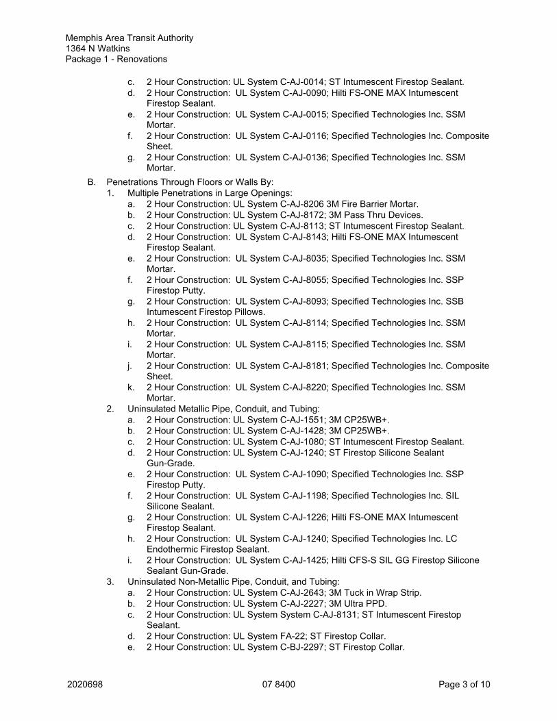
Memphis Area Transit Authority 1364 N WatkinsPackage 1 - Renovations
2020698 07 8400 Page 3 of 10
c. 2 Hour Construction: UL System C-AJ-0014; ST Intumescent Firestop Sealant.d. 2 Hour Construction: UL System C-AJ-0090; Hilti FS-ONE MAX Intumescent
Firestop Sealant.e. 2 Hour Construction: UL System C-AJ-0015; Specified Technologies Inc. SSM
Mortar.f. 2 Hour Construction: UL System C-AJ-0116; Specified Technologies Inc. Composite
Sheet.g. 2 Hour Construction: UL System C-AJ-0136; Specified Technologies Inc. SSM
Mortar.B. Penetrations Through Floors or Walls By:
1. Multiple Penetrations in Large Openings:a. 2 Hour Construction: UL System C-AJ-8206 3M Fire Barrier Mortar.b. 2 Hour Construction: UL System C-AJ-8172; 3M Pass Thru Devices.c. 2 Hour Construction: UL System C-AJ-8113; ST Intumescent Firestop Sealant.d. 2 Hour Construction: UL System C-AJ-8143; Hilti FS-ONE MAX Intumescent
Firestop Sealant.e. 2 Hour Construction: UL System C-AJ-8035; Specified Technologies Inc. SSM
Mortar.f. 2 Hour Construction: UL System C-AJ-8055; Specified Technologies Inc. SSP
Firestop Putty.g. 2 Hour Construction: UL System C-AJ-8093; Specified Technologies Inc. SSB
Intumescent Firestop Pillows.h. 2 Hour Construction: UL System C-AJ-8114; Specified Technologies Inc. SSM
Mortar.i. 2 Hour Construction: UL System C-AJ-8115; Specified Technologies Inc. SSM
Mortar.j. 2 Hour Construction: UL System C-AJ-8181; Specified Technologies Inc. Composite
Sheet.k. 2 Hour Construction: UL System C-AJ-8220; Specified Technologies Inc. SSM
Mortar.2. Uninsulated Metallic Pipe, Conduit, and Tubing:
a. 2 Hour Construction: UL System C-AJ-1551; 3M CP25WB+.b. 2 Hour Construction: UL System C-AJ-1428; 3M CP25WB+.c. 2 Hour Construction: UL System C-AJ-1080; ST Intumescent Firestop Sealant.d. 2 Hour Construction: UL System C-AJ-1240; ST Firestop Silicone Sealant
Gun-Grade.e. 2 Hour Construction: UL System C-AJ-1090; Specified Technologies Inc. SSP
Firestop Putty.f. 2 Hour Construction: UL System C-AJ-1198; Specified Technologies Inc. SIL
Silicone Sealant.g. 2 Hour Construction: UL System C-AJ-1226; Hilti FS-ONE MAX Intumescent
Firestop Sealant.h. 2 Hour Construction: UL System C-AJ-1240; Specified Technologies Inc. LC
Endothermic Firestop Sealant.i. 2 Hour Construction: UL System C-AJ-1425; Hilti CFS-S SIL GG Firestop Silicone
Sealant Gun-Grade.3. Uninsulated Non-Metallic Pipe, Conduit, and Tubing:
a. 2 Hour Construction: UL System C-AJ-2643; 3M Tuck in Wrap Strip.b. 2 Hour Construction: UL System C-AJ-2227; 3M Ultra PPD.c. 2 Hour Construction: UL System System C-AJ-8131; ST Intumescent Firestop
Sealant.d. 2 Hour Construction: UL System FA-22; ST Firestop Collar.e. 2 Hour Construction: UL System C-BJ-2297; ST Firestop Collar.

Memphis Area Transit Authority 1364 N WatkinsPackage 1 - Renovations
2020698 07 8400 Page 4 of 10
f. 2 Hour Construction: UL System C-AJ-2167; Hilti FS-ONE MAX IntumescentFirestop Sealant.
g. 2 Hour Construction: UL System C-AJ-2109; Hilti CP 643N/644 Firestop Collar.h. 2 Hour Construction: UL System C-AJ-2106; Specified Technologies Inc. SSW Wrap
Strips.i. 2 Hour Construction: UL System C-AJ-2282; Specified Technologies Inc. SSW Wrap
Strips.j. 2 Hour Construction: UL System C-AJ-2297; Specified Technologies Inc. SSC
Collars.k. 2 Hour Construction: UL System C-AJ-2297; Specified Technologies Inc. SSW Wrap
Strips.l. 2 Hour Construction: UL System C-AJ-2298; Specified Technologies Inc. LCC
Intumescent Firestop Collars.m. 2 Hour Construction: UL System C-AJ-2588; Specified Technologies Inc. RTC
Range-Taking Collar.n. 2 Hour Construction: UL System C-AJ-2772; Specified Technologies Inc. SSW Wrap
Strips.o. 2 Hour Construction: UL System C-BJ-2021; Hilti CP 643N Firestop Collar.
4. Electrical Cables Not In Conduit:a. 2 Hour Construction: UL System C-AJ-3321; 3M CP25WB+.b. 2 Hour Construction: UL System C-AJ-3393; 3M Plug.c. 2 Hour Construction: UL System C-AJ-3250; 3M Pass Thru Device.d. 2 Hour Construction: UL System C-AJ-3212; ST Firestop Plug.e. 2 Hour Construction: UL System W-J-3182; ST Retrofit Sleeve Kit for existing cables.f. 2 Hour Construction: UL System W-J-3; ST Firestop Sleeve Kit.g. 2 Hour Construction: UL System C-AJ-3260; ST Speed Sleeve.h. 2 Hour Construction: UL System C-AJ-3213; Specified Technologies Inc. LCC
Intumescent Firestop Collars.i. 2 Hour Construction: UL System C-AJ-3213; Specified Technologies Inc. SSC
Collars.j. 2 Hour Construction: UL System W-J-3046; Specified Technologies Inc. SSP
Firestop Putty.k. 2 Hour Construction: UL System C-AJ-3154; Specified Technologies Inc. SSP
Firestop Putty.l. 2 Hour Construction: UL System C-AJ-3216; Hilti CFS-PL Firestop Plug.m. 2 Hour Construction: UL System C-AJ-3283; Hilti CFS-SL SK Firestop Sleeve Kit.n. 2 Hour Construction: UL System C-AJ-3283; Hilti CFS-SL SK Firestop Sleeve Kit
with Hilti CFS-SL GP Gangplate.o. 2 Hour Construction: UL System W-J-3198; Hilti CFS-SL RK Retrofit Sleeve Kit for
Existing Cables.p. 2 Hour Construction: UL System W-J-3199; Hilti CFS-SL SK Firestop Sleeve Kit.
5. Cable Trays with Electrical Cables:a. 2 Hour Construction: UL System C-AJ-4098; 3M FIP1 Step.b. 2 Hour Construction: UL System C-AJ-4094; Hilti CFS-BL Firestop Block.
6. Electrical Busways:a. 2 Hour Construction: Nothing available for 2 ½ concrete.b. 2 Hour Construction thru concrete wall: C-AJ-6002; 3M FB1000NS.
7. Insulated Pipes:a. 2 Hour Construction: UL System C-AJ-5209; 3M CP25WB+.b. 2 Hour Construction: UL System C-AJ-5080; 3M CP25WB+.c. 2 Hour Construction: UL System C-AJ-5087; ST intumescent Firestop Sealant.d. 2 Hour Construction: UL System C-AJ-5010; ST Intumescent Firestop Sealant.
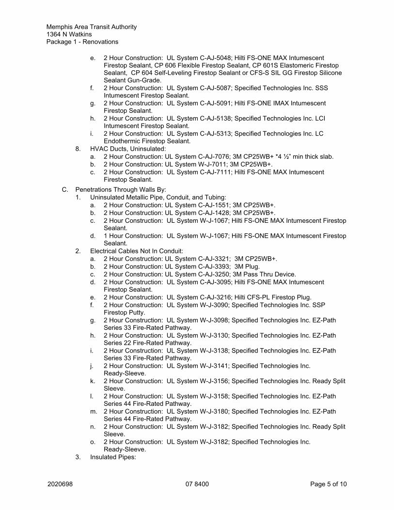
Memphis Area Transit Authority 1364 N WatkinsPackage 1 - Renovations
2020698 07 8400 Page 5 of 10
e. 2 Hour Construction: UL System C-AJ-5048; Hilti FS-ONE MAX IntumescentFirestop Sealant, CP 606 Flexible Firestop Sealant, CP 601S Elastomeric FirestopSealant, CP 604 Self-Leveling Firestop Sealant or CFS-S SIL GG Firestop SiliconeSealant Gun-Grade.
f. 2 Hour Construction: UL System C-AJ-5087; Specified Technologies Inc. SSSIntumescent Firestop Sealant.
g. 2 Hour Construction: UL System C-AJ-5091; Hilti FS-ONE IMAX IntumescentFirestop Sealant.
h. 2 Hour Construction: UL System C-AJ-5138; Specified Technologies Inc. LCIIntumescent Firestop Sealant.
i. 2 Hour Construction: UL System C-AJ-5313; Specified Technologies Inc. LCEndothermic Firestop Sealant.
8. HVAC Ducts, Uninsulated:a. 2 Hour Construction: UL System C-AJ-7076; 3M CP25WB+ *4 ½” min thick slab.b. 2 Hour Construction: UL System W-J-7011; 3M CP25WB+.c. 2 Hour Construction: UL System C-AJ-7111; Hilti FS-ONE MAX Intumescent
Firestop Sealant.C. Penetrations Through Walls By:
1. Uninsulated Metallic Pipe, Conduit, and Tubing:a. 2 Hour Construction: UL System C-AJ-1551; 3M CP25WB+.b. 2 Hour Construction: UL System C-AJ-1428; 3M CP25WB+.c. 2 Hour Construction: UL System W-J-1067; Hilti FS-ONE MAX Intumescent Firestop
Sealant.d. 1 Hour Construction: UL System W-J-1067; Hilti FS-ONE MAX Intumescent Firestop
Sealant.2. Electrical Cables Not In Conduit:
a. 2 Hour Construction: UL System C-AJ-3321; 3M CP25WB+.b. 2 Hour Construction: UL System C-AJ-3393; 3M Plug.c. 2 Hour Construction: UL System C-AJ-3250; 3M Pass Thru Device.d. 2 Hour Construction: UL System C-AJ-3095; Hilti FS-ONE MAX Intumescent
Firestop Sealant.e. 2 Hour Construction: UL System C-AJ-3216; Hilti CFS-PL Firestop Plug.f. 2 Hour Construction: UL System W-J-3090; Specified Technologies Inc. SSP
Firestop Putty.g. 2 Hour Construction: UL System W-J-3098; Specified Technologies Inc. EZ-Path
Series 33 Fire-Rated Pathway.h. 2 Hour Construction: UL System W-J-3130; Specified Technologies Inc. EZ-Path
Series 22 Fire-Rated Pathway.i. 2 Hour Construction: UL System W-J-3138; Specified Technologies Inc. EZ-Path
Series 33 Fire-Rated Pathway.j. 2 Hour Construction: UL System W-J-3141; Specified Technologies Inc.
Ready-Sleeve.k. 2 Hour Construction: UL System W-J-3156; Specified Technologies Inc. Ready Split
Sleeve.l. 2 Hour Construction: UL System W-J-3158; Specified Technologies Inc. EZ-Path
Series 44 Fire-Rated Pathway.m. 2 Hour Construction: UL System W-J-3180; Specified Technologies Inc. EZ-Path
Series 44 Fire-Rated Pathway.n. 2 Hour Construction: UL System W-J-3182; Specified Technologies Inc. Ready Split
Sleeve.o. 2 Hour Construction: UL System W-J-3182; Specified Technologies Inc.
Ready-Sleeve.3. Insulated Pipes:

Memphis Area Transit Authority 1364 N WatkinsPackage 1 - Renovations
2020698 07 8400 Page 6 of 10
a. 2 Hour Construction: UL System C-AJ-5209; 3M CP25WB+.b. 2 Hour Construction: UL System C-AJ-5080; 3M CP25WB+.c. 2 Hour Construction: UL System C-AJ-5090; Hilti FS-ONE MAX Intumescent
Firestop Sealant.d. 2 Hour Construction: UL System C-AJ-5091; Hilti FS-ONE MAX Intumescent
Firestop Sealant.e. 1 Hour Construction: UL System C-AJ-5090; Hilti FS-ONE MAX Intumescent
Firestop Sealant.f. 1 Hour Construction: UL System C-AJ-5091; Hilti FS-ONE MAX Intumescent
Firestop Sealant.4. HVAC Ducts, Uninsulated:
a. 2 Hour Construction: UL System W-J-7092; Specified Technologies Inc. FyreFlangeHVAC Firestop Angle.
b. 2 Hour Construction: UL System C-AJ-7076; 3M CP25WB+ *4 ½” min thick slab.c. 2 Hour Construction: UL System W-J-7011; 3M CP25WB+.d. 2 Hour Construction: UL System W-J-7109; Hilti FS-ONE MAX Intumescent Firestop
Sealant, or CP 606 Flexible Firestop Sealant.5. HVAC Ducts, Insulated
a. 2 Hour Construction: UL System W-J-7114; 3M CP25WB+.b. 2 Hour Construction: UL System W-J-7112; Hilti FS-ONE MAX Intumescent Firestop
Sealant.2.05 FIRESTOPPING PENETRATIONS THROUGH GYPSUM BOARD WALLS
A. Blank Openings:1. 1-2 Hour Construction: UL System W-L-0031; 3M CP25WB+.2. 1-2 Hour Construction: UL System W-L-0036; 3M DT100, 200, 4003. 1-2 Hour Construction: UL System W-L-0041; 3M Pass Thru Device4. 1-2 Hour Construction: UL System W-L-3356; ST Speed Sleeve.5. 1 Hour Construction: UL System W-L-0020; Specified Technologies Inc. Composite
Sheet.6. 1 Hour Construction: UL System W-L-0032; Specified Technologies Inc. FP Intumescent
Firestop Plug.7. 1 Hour Construction: UL System W-L-0038; Specified Technologies Inc. FP Intumescent
Firestop Plug.8. 1 Hour Construction: UL System W-L-3334; Hilti CP 653 Speed Sleeve.
B. Penetrations By:1. Multiple Penetrations in Large Openings:
a. 1-2 Hour Construction: UL System W-L-1526; 3M Fire Barrier Block, 3M FIP1 Step.b. 1-2 Hour Construction: UL System W-L-8106; 3M Fire Barrier Block/Planks, 3M FIP1
Step, 3M Tuck In Wrap Strips.c. 1-2 Hour Construction: UL System W-L-8069; 3M Pass Thru Devices.d. 1-2 Hour Construction: UL System W-L-8049; 3M CP25WB+.e. 1-2 Hour Construction: UL System W-L-1500; 3M Moldable Putty Pads *med gas
boxes.f. 1 Hour Construction: UL System W-L-1168; ST Intumescent Firestop Sealant.g. 1 Hour Construction: UL System W-L-8056; ST Intumescent Firestop Sealant.h. 1 Hour Construction: UL System W-L-8026; ST Intumescent Firestop Sealant.i. 1 Hour Construction: UL System W-L-8005; ST Firestop Block.j. 1 Hour Construction: UL System W-L-1408; Hilti FS-ONE MAX Intumescent Firestop
Sealant.k. 1 Hour Construction: UL System W-L-8013; Hilti CFS-BL Firestop Block.l. 1 Hour Construction: UL System W-L-8025; Specified Technologies Inc. LCI
Intumescent Firestop Sealant.

Memphis Area Transit Authority 1364 N WatkinsPackage 1 - Renovations
2020698 07 8400 Page 7 of 10
m. 1 Hour Construction: UL System W-L-8050; Specified Technologies Inc. SSBIntumescent Firestop pillows.
n. 1 Hour Construction: UL System W-L-8071; Hilti FS-ONE MAX Intumescent FirestopSealant.
o. 1 Hour Construction: UL System W-L-8073; Specified Technologies Inc. CompositeSheet.
p. 1 Hour Construction: UL System W-L-8079; Hilti FS-ONE MAX Intumescent FirestopSealant.
2. Uninsulated Metallic Pipe, Conduit, and Tubing:a. 1-2 Hour Construction: UL System W-L-1296; 3M CP25WB+.b. 1-2 Hour Construction: UL System W-L-1450; 3M CP25WB+ *allows continuous pt
contact.c. 1-2 Hour Construction: UL System W-L-1413; 3M CP25WB+ shaft wall.d. 1-2 Hour Construction: UL System W-L-7168; 3M EMat large steel boxes.e. 1 Hour Construction: UL System W-L-1049; ST Intumescent Firestop Sealant.f. 1 Hour Construction: UL System W-L-1042; Specified Technologies Inc. WF300
Intumescent Firestop Caulk (For Wood Frame Construction).g. 1 Hour Construction: UL System W-L-1049; Specified Technologies Inc. SSS
Intumescent Firestop Sealant.h. 1 Hour Construction: UL System W-L-1054; Hilti FS-ONE MAX Intumescent Firestop
Sealant.i. 1 Hour Construction: UL System W-L-1090; Specified Technologies Inc. LC
Endothermic Firestop Sealant.j. 1 Hour Construction: UL System W-L-1164; Hilti FS-ONE MAX Intumescent Firestop
Sealant.k. 1 Hour Construction: UL System W-L-1222; Specified Technologies Inc. LCI
Intumescent Firestop Sealant.l. 1 Hour Construction: UL System W-L-1477; Specified Technologies Inc. EZ Firestop
Grommet.m. 1 Hour Construction: UL System W-L-1506; Hilti CFS-D Firestop Cable Disc.
3. Uninsulated Non-Metallic Pipe, Conduit, and Tubing:a. 1-2 Hour Construction: UL System W-L-2162; 3M Ultra PPD.b. 1-2 Hour Construction: UL System W-L-2299; 3M CP25WB+, *3M IC15WB+(use with
CPVC Pipe).c. 1 Hour Construction: UL System W-L-2048; Specified Technologies Inc. SSW Wrap
Strips.d. 1 Hour Construction: UL System W-L-2074; Specified Technologies Inc. SSC
Collars.e. 1 Hour Construction: UL System W-L-2078; Hilti CP 643N/644 Firestop Collar.f. 1 Hour Construction: UL System W-L-2128; Hilti FS-ONE MAX Intumescent Firestop
Sealant.g. 1 Hour Construction: UL System W-L-2237; Specified Technologies Inc. LCC
Intumescent Firestop Collars.h. 1 Hour Construction: UL System W-L-2241; Specified Technologies Inc. WF300
Intumescent Firestop Caulk (For Wood Frame Construction).i. 1 Hour Construction: UL System W-L-2243; Specified Technologies Inc. SSW Wrap
Strips.j. 1 Hour Construction: UL System W-L-2493; Specified Technologies Inc. RTC
Range-Taking Collar.4. Electrical Cables Not In Conduit:
a. 1-2 Hour Construction: UL System W-L-3195; 3M CP25WB+.b. 1-2 Hour Construction: UL System W-L-3371; 3M DT100, DT200, DT400 sleeves.c. 1-2 Hour Construction: UL System W-L-3289; 3M Pass Thru Devices.

Memphis Area Transit Authority 1364 N WatkinsPackage 1 - Renovations
2020698 07 8400 Page 8 of 10
d. 1-2 Hour Construction: UL System W-L-3347; 3M FIP1 Step.e. 1-2 Hour Construction; UL System W-L-3426; 3M Fire Barrier Plug.f. 1 Hour Construction: UL System W-L-3303; ST Sleeve Kit for existing cables.g. 1 Hour Construction: UL System W-L-3210; ST Intumescent Firestop Sealant.h. 1 Hour Construction: UL System W-L-3356; ST Speed Sleeve.i. 1 Hour Construction: UL System W-L-3024; Specified Technologies Inc. SSP
Firestop Putty.j. 1 Hour Construction: UL System W-L-3065; Hilti FS-ONE MAX Intumescent Firestop
Sealant, CP 606 Flexible Firestop Sealant, CD 601S Elastomeric Firestop Sealant, orCP 618 Firestop Putty Stick.
k. 1 Hour Construction: UL System W-L-3076; Specified Technologies Inc. SSSIntumescent Firestop Sealant.
l. 1 Hour Construction: UL System W-L-3084; Specified Technologies Inc. SSBIntumescent Firestop Pillows.
m. 1 Hour Construction: UL System W-L-3135; Specified Technologies Inc. SSPFirestop Putty.
n. 1 Hour Construction: UL System W-L-3169; Specified Technologies Inc. LCIIntumescent Firestop Sealant.
o. 1 Hour Construction: UL System W-L-3218; Specified Technologies Inc. EZ-PathSeries 33 Fire-Rated Pathway.
p. 1 Hour Construction: UL System W-L-3255; Specified Technologies Inc. EZ-PathSeries 22 Fire-Rated Pathway.
q. 1 Hour Construction: UL System W-L-3256; Specified Technologies Inc. EZ-PathSeries 22 Fire-Rated Pathway.
r. 1 Hour Construction: UL System W-L-3265; Specified Technologies Inc. EZ-PathSeries 33 Fire-Rated Pathway.
s. 1 Hour Construction: UL System W-L-3303; Specified Technologies Inc. Ready SplitSleeve.
t. 1 Hour Construction: UL System W-L-3306; Specified Technologies Inc. EZ-PathSeries 44 Fire-Rated Pathway.
u. 1 Hour Construction: UL System W-L-3334; Hilti CP 653 Speed Sleeve.v. 1 Hour Construction: UL System W-L-3350; Specified Technologies Inc. LC
Endothermic Firestop Sealant.w. 1 Hour Construction: UL System W-L-3357; Specified Technologies Inc. FP
Intumescent Firestop Plug.x. 1 Hour Construction: UL System W-L-3358; Specified Technologies Inc. Ready Split
Sleeve.y. 1 Hour Construction: UL System W-L-3358; Specified Technologies Inc.
Ready-Sleeve.z. 1 Hour Construction: UL System W-L-3369; Specified Technologies Inc. EZ Firestop
Grommet.aa. 1 Hour Construction: UL System W-L-3370; Specified Technologies Inc. EZ Firestop
Grommet.ab. 1 Hour Construction: UL System W-L-3374; Specified Technologies Inc. FP
Intumescent Firestop Plug.ac. 1 Hour Construction: UL System W-L-3376; Specified Technologies Inc.
Ready-Sleeve.ad. 1 Hour Construction: UL System W-L-3377; Specified Technologies Inc. EZ-Path
Series 22 Fire-Rated Pathway.ae. 1 Hour Construction: UL System W-L-3377; Specified Technologies Inc. EZ-Path
Series 33 Fire-Rated Pathway.af. 1 Hour Construction: UL System W-L-3378; Specified Technologies Inc. EZ Firestop
Grommet.

Memphis Area Transit Authority 1364 N WatkinsPackage 1 - Renovations
2020698 07 8400 Page 9 of 10
ag. 1 Hour Construction: UL System W-L-3379; Specified Technologies Inc. EZ FirestopGrommet.
ah. 1 Hour Construction: UL System W-L-3390; Specified Technologies Inc. EZ-PathSeries 44 Fire-Rated Pathway.
ai. 1 Hour Construction: UL System W-L-3393; Hilti CFS-SL RK Retrofit Sleeve Kit forExisting Cables.
aj. 1 Hour Construction: UL System W-L-3414; Hilti CFS-D Firestop Cable Disc.5. Cable Trays with Electrical Cables:
a. 1-2 Hour Construction: UL System W-L-4090; 3M Fire Barrier Blocks, 3M FIP1 Step,3M CP25WB+.
b. 1-2 Hour Construction: UL System W-L-4098; 3M FIP1 Step.c. 1 Hour Construction: UL System W-L-4079; ST Firestop Block.d. 1 Hour Construction: UL System W-L-4008; Specified Technologies Inc. SSB
Intumescent Firestop Pillows.e. 1 Hour Construction: UL System W-L-4011; Hilti CFS-BL Firestop Block.f. 1 Hour Construction: UL System W-L-4060; Hilti FS-ONE MAX Intumescent Firestop
Sealant.6. Insulated Pipes:
a. 1-2 Hour Construction: UL System W-L-5168; 3M CP25WB+.b. 1-2 Hour Construction: UL System W-L-5169; 3M CP25WB+.c. 1 Hour Construction: UL System W-L-5122; ST Intumescent Firestop Sealant.d. 1 Hour Construction: UL System W-L-5014; Specified Technologies Inc. SSS
Intumescent Firestop Sealant.e. 1 Hour Construction: UL System W-L-5028; Hilti FS-ONE MAX Intumescent Firestop
Sealant.f. 1 Hour Construction: UL System W-L-5029; Hilti FS-ONE Intumescent Firestop
Sealant.g. 1 Hour Construction: UL System W-L-5121; Specified Technologies Inc. LCI
Intumescent Firestop Sealant.h. 1 Hour Construction: UL System W-L-5273; Specified Technologies Inc. LC
Endothermic Firestop Sealant.i. 1 Hour Construction: UL System W-L-5298; Specified Technologies Inc. WF300
Intumescent Firestop Caulk (For Wood Frame Construction).7. HVAC Ducts, Insulated:
a. 1-2 Hour Construction: UL System W-L-7152; 3M FB3000WT.b. 1-2 Hour Construction: UL System W-L-7177; 3M FB3000WT.c. 2 Hour Construction: UL System W-L-7025; ST Intumescent Firestop Sealant.d. 1 Hour Construction: UL System W-L-7025; ST Intumescent Firestop Sealant.e. 1 Hour Construction: UL System W-L-7164; Specified Technologies Inc. FyreFlange
HVAC Firestop Angle.f. 1 Hour Construction: UL System W-L-7238; Specified Technologies Inc. FyreFlange
HVAC Firestop Angle.g. 1 Hour Construction: UL System W-L-7156; Hilti FS-ONE MAX Intumescent Firestop
Sealant.2.06 FIRESTOPPING SYSTEMS
A. Firestopping: Materials that are compatible with adjacent construction.1. Fire Ratings: Use system that is listed by FM (AG), ITS (DIR), or UL (FRD) and tested in
accordance with ASTM E814, ASTM E119, or UL 1479 with F Rating equal to fire rating ofpenetrated assembly and minimum T Rating Equal to F Rating and in compliance withother specified requirements.
2. Provide sleeves, collars, sealants and any other accessory required for a completeinstallation.

Memphis Area Transit Authority 1364 N WatkinsPackage 1 - Renovations
2020698 07 8400 Page 10 of 10
PART 3 EXECUTION3.01 INSTALLATION
A. Install materials in manner described in fire test report and in accordance with manufacturer'sinstructions, completely closing openings.
B. Do not cover installed firestopping until inspected by authorities having jurisdiction.C. Label each penetration, identify firestopping system.D. Install labeling required by code.
3.02 FIELD QUALITY CONTROLA. Record location of penetrations through fire rated partitions on a floor plan for Owner's record.
Drawing is to be of sufficient scale to clearly indicate the location of penetrations. Indicate firerating of partitions and include identification of firestop system used at each location.
3.03 CLEANINGA. Clean adjacent surfaces of firestopping materials.
3.04 PROTECTIONA. Protect adjacent surfaces from damage by material installation.B. Protect firestopping materials from damage on surfaces subject to traffic.C. Repair firestopping damaged by work of other trades.
END OF SECTION

Memphis Area Transit Authority 1364 N WatkinsPackage 1 - Renovations
2020698 07 9200 Page 1 of 6
SECTION 07 9200JOINT SEALANTS
PART 1 GENERAL1.01 SECTION INCLUDES
A. Nonsag gunnable joint sealants.B. Joint backings and accessories.
1.02 RELATED REQUIREMENTSA. Section 01 6116 - Volatile Organic Compound (VOC) Content Restrictions: Additional
requirements for sealants and primers.B. Section 07 8400 - Firestopping: Firestopping sealants.C. Section 08 7100 - Door Hardware: Setting exterior door thresholds in sealant.D. Section 09 2116 - Gypsum Board Assemblies: Sealing acoustical and sound-rated walls and
ceilings.E. Section 09 3000 - Tiling: Sealant between tile and plumbing fixtures and at junctions with other
materials and changes in plane.1.03 REFERENCE STANDARDS
A. ASTM C794 - Standard Test Method for Adhesion-In-Peel of Elastomeric Joint Sealants; 2018.B. ASTM C834 - Standard Specification for Latex Sealants; 2017.C. ASTM C920 - Standard Specification for Elastomeric Joint Sealants; 2018.D. ASTM C1087 - Standard Test Method for Determining Compatibility of Liquid-Applied Sealants
with Accessories Used in Structural Glazing Systems; 2016.E. ASTM C1193 - Standard Guide for Use of Joint Sealants; 2016.F. ASTM C1311 - Standard Specification for Solvent Release Sealants; 2014.G. ASTM C1330 - Standard Specification for Cylindrical Sealant Backing for Use with Cold
Liquid-Applied Sealants; 2018.1.04 SUBMITTALS
A. See Section 01 3000 - Administrative Requirements, for submittal procedures.B. Product Data for Sealants: Submit manufacturer's technical data sheets for each product to be
used, that includes the following.1. Physical characteristics, including movement capability, VOC content, hardness, cure
time, and color availability.2. List of backing materials approved for use with the specific product.3. Substrates that product is known to satisfactorily adhere to and with which it is compatible.4. Substrates the product should not be used on.5. Substrates for which use of primer is required.
C. Product Data for Accessory Products: Submit manufacturer's technical data sheet for eachproduct to be used, including physical characteristics, installation instructions, andrecommended tools.
D. Color Cards for Selection: Where sealant color is not specified, submit manufacturer's colorcards showing standard colors available for selection.
E. Preconstruction Laboratory Test Reports: Submit at least four weeks prior to start ofinstallation.
F. Preinstallation Field Adhesion Test Reports: Submit filled out Preinstallation Field AdhesionTest Reports log within 10 days after completion of tests; include bagged test samples andphotographic records.

2020698 07 9200 Page 2 of 6
Memphis Area Transit Authority 1364 N WatkinsPackage 1 - Renovations
1.05 QUALITY ASSURANCEA. Manufacturer Qualifications: Company specializing in manufacturing the products specified in
this section with minimum three years documented experience.B. Installer Qualifications: Company specializing in performing the work of this section and with at
least three years of documented experience.C. Preconstruction Laboratory Testing: Arrange for sealant manufacturer(s) to test each
combination of sealant, substrate, backing, and accessories.1. Adhesion Testing: In accordance with ASTM C794.2. Compatibility Testing: In accordance with ASTM C1087.3. Allow sufficient time for testing to avoid delaying the work.4. Deliver to manufacturer sufficient samples for testing.5. Report manufacturer's recommended corrective measures, if any, including primers or
techniques not indicated in product data submittals.6. Testing is not required if sealant manufacturer provides data showing previous testing, not
older than 24 months, that shows satisfactory adhesion, lack of staining, and compatibility.1.06 WARRANTY
A. See Section 01 7800 - Closeout Submittals, for additional warranty requirements.B. Correct defective work within a five year period after Date of Substantial Completion.C. Warranty: Include coverage for installed sealants and accessories that fail to achieve
watertight seal , exhibit loss of adhesion or cohesion, or do not cure.PART 2 PRODUCTS2.01 MANUFACTURERS
A. Non-Sag Sealants: Permits application in joints on vertical surfaces without sagging orslumping.1. Manufacturers, not limited to the following:
a. Dow Corning Corporation: www.dowcorning.com/construction/sle.b. GE Silicones: www.siliconeforbuilding.comc. Master Builders Solutions by BASF:
www.master-builders-solutions.basf.us/en-us/#sle.d. Momentive Performance Materials, Inc (formerly GE Silicones):
www.momentive.com.e. Pecora Corporation: www.pecora.com.f. Sika Corporation: www.usa-sika.com.g. Tremco Commercial Sealants & Waterproofing: www.tremcosealants.com/#sle.h. W.R. Meadows, Inc: www.wrmeadows.com/#sle.i. Substitutions: See Section 01 6000 - PRODUCT REQUIREMENTS.
2.02 JOINT SEALANT APPLICATIONSA. Scope:
1. Interior Joints: Do not seal interior joints unless specifically indicated to be sealed. Interiorjoints to be sealed include, but are not limited to, the following items.a. Joints between door, window, and other frames and adjacent construction.b. Joints between casework and adjacent construction.c. Joints between water closets and adjacent construction.d. Other joints indicated below.
2. Do not seal the following types of joints.a. Joints where sealant is specified to be provided by manufacturer of product to be
sealed.b. Joints where installation of sealant is specified in another section.c. Joints between suspended panel ceilings/grid and walls.

Memphis Area Transit Authority 1364 N WatkinsPackage 1 - Renovations
2020698 07 9200 Page 3 of 6
B. Interior Joints: Use nonsag Acrylic Emulsion Latex sealant, unless otherwise indicated.1. Wall and Ceiling Joints in Non-Wet Areas: Acrylic emulsion latex sealant.2. Joints between Fixtures in Wet Areas and Floors, Walls, and Ceilings: Mildew-resistant
silicone sealant; white.C. Interior Wet Areas: Bathrooms and restrooms; fixtures in wet areas include plumbing fixtures,
countertops, cabinets, and other similar items.2.03 JOINT SEALANTS - GENERAL
A. Sealants and Primers: Provide products with levels of volatile organic compound (VOC)content as indicated in Section 01 6116.
2.04 NONSAG JOINT SEALANTSA. Mildew-Resistant Silicone Sealant: ASTM C920, Grade NS, Uses M and A; single component,
mildew resistant; not expected to withstand continuous water immersion or traffic.1. Color: White.2. Application:
a. Interior joints between plumbing fixtures and floor and wall surfaces.b. Interior joints between kitchen and toilet room countertops and wall surfaces.c. Sanitary seals at toilet areas.
3. Manufacturers, not limited to those listed below:a. Dow Corning Corporation: 786 Mildew Resistant Silicone Sealant.b. GE Silicones: SCS 1700 Series.c. Pecora Corporation; 898ST Sanitary Silicone Sealant - Class 50: www.pecora.com.d. Sika Corporation; Sikasil GP: www.usa-sika.com.e. Tremco Global Sealants: Tremsil 200.f. Substitutions: See Section 01 6000 - PRODUCT REQUIREMENTS.
B. Acrylic Emulsion Latex: Water-based; ASTM C834, single component, non-staining,non-bleeding, non-sagging; not intended for exterior use.1. Color: To be selected by Architect from manufacturer's standard range.2. Grade: ASTM C834; Grade Minus 18 Degrees C (0 Degrees F).3. Applications: Use for:
a. Interior wall and ceiling control joints.b. Interior joints between door and window frames and wall surfaces.c. Interior joints between edge of gypsum board and floor.d. Interior joints between edge of gypsum board and structure above.e. Interior joints between millwork/casework and wall surfacesf. Other interior joints for which no other type of sealant is indicated.
4. Manufacturers, not limited to those listed below:a. BASF Construction Chemicals-Building Systems; Sonneborn Sonolac.b. Pecora Corporation; AC-20 + Silicone Acrylic Latex Caulking Compound:
www.pecora.com.c. Tremco Commercial Sealants & Waterproofing; Tremflex 834:
www.tremcosealants.com/#sle.d. Substitutions: See Section 01 6000 - PRODUCT REQUIREMENTS.
C. Non-Curing Butyl Sealant: Solvent-based; ASTM C1311; single component, non-sag,non-skinning, non-hardening, non-bleeding; vapor-impermeable; intended for fully concealedapplications.1. Application: Concealed locations.
a. Sealant bead between top stud runner and structure and between bottom stud trackand floor.
b. Bedding of electrical boxes in wall systems.2. Manufacturers, not limited to those listed below:

Memphis Area Transit Authority 1364 N WatkinsPackage 1 - Renovations
2020698 07 9200 Page 4 of 6
a. Pecora; BA-98 Non-Skinning Butyl Sealant.b. Sika; SikaLastomer - 511 Non-skinning Butyl Sealant.c. Tremco Global Sealants; Acoustical/Curtainwall Sealant.d. Substitutions: See Section 01 6000 - PRODUCT REQUIREMENTS.
2.05 ACCESSORIESA. Backer Rod: Cylindrical cellular foam rod with surface that sealant will not adhere to,
compatible with specific sealant used, and recommended by backing and sealantmanufacturers for specific application.1. Type for Joints Not Subject to Pedestrian or Vehicular Traffic: ASTM C1330; Type O -
Open Cell Polyurethane.2. Type for Joints Subject to Pedestrian or Vehicular Traffic: ASTM C1330; Type B -
Bi-Cellular Polyethylene.3. Open Cell: 40 to 50 percent larger in diameter than joint width.4. Closed Cell and Bi-Cellular: 25 to 33 percent larger in diameter than joint width.
B. Backing Tape: Self-adhesive polyethylene tape with surface that sealant will not adhere to andrecommended by tape and sealant manufacturers for specific application.
C. Masking Tape: Self-adhesive, nonabsorbent, non-staining, removable without adhesiveresidue, and compatible with surfaces adjacent to joints and sealants.
D. Joint Cleaner: Non-corrosive and non-staining type, type recommended by sealantmanufacturer; compatible with joint forming materials.
E. Primers: Type recommended by sealant manufacturer to suit application; non-staining.PART 3 EXECUTION3.01 EXAMINATION
A. Verify that joints are ready to receive work.B. Verify that backing materials are compatible with sealants.C. Verify that backer rods are of the correct size.D. Preinstallation Adhesion Testing: Install a sample for each test location indicated in the test
plan.1. Test each sample as specified in PART 1 under QUALITY ASSURANCE article.2. Notify Architect of date and time that tests will be performed, at least seven days in
advance.3. Arrange for sealant manufacturer's technical representative to be present during tests.4. Record each test on Preinstallation Adhesion Test Log as indicated.5. If any sample fails, review products and installation procedures, consult manufacturer, or
take whatever other measures are necessary to ensure adhesion; re-test in a differentlocation; if unable to obtain satisfactory adhesion, report to Architect.
6. After completion of tests, remove remaining sample material and prepare joint for newsealant installation.
3.02 PREPARATIONA. Remove loose materials and foreign matter that could impair adhesion of sealant.B. Clean joints, and prime as necessary, in accordance with manufacturer's instructions.C. Perform preparation in accordance with manufacturer's instructions and ASTM C1193.D. Mask elements and surfaces adjacent to joints from damage and disfigurement due to sealant
work; be aware that sealant drips and smears may not be completely removable.E. Concrete Floor Joints That Will Be Exposed in Completed Work: Test joint filler in
inconspicuous area to verify that it does not stain or discolor slab.
2020698 07 9200 Page 5 of 6
Memphis Area Transit Authority 1364 N WatkinsPackage 1 - Renovations
3.03 INSTALLATIONA. Perform work in accordance with sealant manufacturer's requirements for preparation of
surfaces and material installation instructions.B. Perform installation in accordance with ASTM C1193.C. Measure joint dimensions and size joint backers to achieve width-to-depth ratio, neck
dimension, and surface bond area as recommended by manufacturer, except where specificdimensions are indicated.
D. Install bond breaker backing tape where backer rod cannot be used.E. Install sealant free of air pockets, foreign embedded matter, ridges, and sags, and without
getting sealant on adjacent surfaces.F. Do not install sealant when ambient temperature is outside manufacturer's recommended
temperature range, or will be outside that range during the entire curing period, unlessmanufacturer's approval is obtained and instructions are followed.
G. Nonsag Sealants: Tool surface concave, unless otherwise indicated; remove masking tapeimmediately after tooling sealant surface.
3.04 POST-OCCUPANCYA. Post-Occupancy Inspection: Perform visual inspection of entire length of project sealant joints
at a time that joints have opened to their greatest width; i.e. at low temperature in thermal cycle.Report failures immediately and repair.
END OF SECTION

Memphis Area Transit Authority 1364 N WatkinsPackage 1 - Renovations
2020698 07 9200 Page 6 of 6

Memphis Area Transit Authority1364 N WatkinsPackage 1 - Renovations
2020698 08 1213 Page 1 of 4
SECTION 08 1213HOLLOW METAL FRAMES
PART 1 GENERAL1.01 SECTION INCLUDES
A. Non-fire-rated hollow metal frames for non-hollow metal doors.B. Fire-rated hollow metal frames for non-hollow metal doors.C. Interior glazed borrowed lite frames.
1.02 RELATED REQUIREMENTSA. Section 08 1416 - Flush Wood Doors: Non-hollow metal door for hollow metal frames.B. Section 08 7100 - Door Hardware: Hardware, silencers, and weatherstripping.C. Section 08 8000 - Glazing: Glazed borrowed lites.D. Section 09 9123 - Interior Painting: Field painting.
1.03 REFERENCE STANDARDSA. ADA Standards - Americans with Disabilities Act (ADA) Standards for Accessible Design; 2010.B. ANSI/SDI A250.4 - Test Procedure and Acceptance Criteria for Physical Endurance for Steel
Doors, Frames and Frame Anchors; 2011.C. ANSI/SDI A250.8 - Specifications for Standard Steel Doors and Frames (SDI-100); 2017.D. ANSI/SDI A250.10 - Test Procedure and Acceptance Criteria for Prime Painted Steel Surfaces
for Steel Doors and Frames; 2011.E. ASTM A653/A653M - Standard Specification for Steel Sheet, Zinc-Coated (Galvanized) or
Zinc-Iron Alloy-Coated (Galvannealed) by the Hot-Dip Process; 2020.F. ASTM A1008/A1008M - Standard Specification for Steel, Sheet, Cold-Rolled, Carbon,
Structural, High-Strength Low-Alloy, High-Strength Low-Alloy with Improved Formability,Required Hardness, Solution Hardened, and Bake Hardenable; 2020.
G. ASTM A1011/A1011M - Standard Specification for Steel, Sheet and Strip, Hot-Rolled, Carbon,Structural, High-Strength Low-Alloy, High-Strength Low-Alloy with Improved Formability, andUltra-High Strength; 2018a.
H. ASTM C143/C143M - Standard Test Method for Slump of Hydraulic-Cement Concrete; 2020.I. ASTM C476 - Standard Specification for Grout for Masonry; 2020.J. BHMA A156.115 - American National Standard for Hardware Preparation in Steel Doors and
Steel Frames; 2016.K. ICC A117.1 - Accessible and Usable Buildings and Facilities; 2017.L. ITS (DIR) - Directory of Listed Products; current edition.M. NAAMM HMMA 830 - Hardware Selection for Hollow Metal Doors and Frames; 2002.N. NAAMM HMMA 831 - Hardware Locations for Hollow Metal Doors and Frames; 2011.O. NAAMM HMMA 840 - Guide Specifications For Receipt, Storage and Installation of Hollow
Metal Doors and Frames; 2007.P. NAAMM HMMA 861 - Guide Specifications for Commercial Hollow Metal Doors and Frames;
2014.Q. NFPA 80 - Standard for Fire Doors and Other Opening Protectives; 2019.R. NFPA 105 - Standard for Smoke Door Assemblies and Other Opening Protectives; 2019.S. SDI 117 - Manufacturing Tolerances for Standard Steel Doors and Frames; 2013.T. UL (DIR) - Online Certifications Directory; Current Edition.
Memphis Area Transit Authority1364 N WatkinsPackage 1 - Renovations
2020698 08 1213 Page 2 of 4
U. UL 10C - Standard for Positive Pressure Fire Tests of Door Assemblies; Current Edition,Including All Revisions.
V. UL 1784 - Standard for Air Leakage Tests of Door Assemblies; Current Edition, Including AllRevisions.
1.04 SUBMITTALSA. See Section 01 3000 - Administrative Requirements for submittal procedures.B. Product Data: Materials and details of design and construction, hardware locations,
reinforcement type and locations, anchorage and fastening methods, and finishes.C. Shop Drawings: Details of each opening, showing elevations, glazing, frame profiles, and
identifying location of different finishes, if any.D. Manufacturer's Qualification Statement.E. Installer's Qualification Statement.
1.05 QUALITY ASSURANCEA. Manufacturer Qualifications: Company specializing in manufacturing products specified in this
section, with not less than three years of documented experience.B. Installer Qualifications: Company specializing in performing work of the type specified and with
at least three years of documented experience.1.06 DELIVERY, STORAGE, AND HANDLING
A. Store in accordance with applicable requirements and in compliance with standards and/orcustom guidelines as indicated.
PART 2 PRODUCTS2.01 MANUFACTURERS
A. Hollow Metal Frames with Integral Casings:1. Ceco Door, an Assa Abloy Group company: www.assaabloydss.com.2. Curries, an Assa Abloy Group company: www.assaabloydss.com.3. Republic Doors, an Allegion brand: www.republicdoor.com/#sle.4. Steelcraft, an Allegion brand: www.allegion.com/us.5. Substitutions: See Section 01 6000 - PRODUCT REQUIREMENTS.
2.02 PERFORMANCE REQUIREMENTSA. Refer to Door and Frame Schedule on drawings for frame sizes, fire ratings, sound ratings,
finishing, door hardware to be installed, and other variations, if any.B. Door Frame Type: Provide hollow metal door frames with integral casings.
1. Interior Doors: Use frames with integral casings.C. Steel Sheet: Comply with one or more of the following requirements; galvannealed steel
complying with ASTM A653/A653M, cold-rolled steel complying with ASTM A1008/A1008M, orhot-rolled pickled and oiled (HRPO) steel complying with ASTM A1011/A1011M, commercialsteel (CS) Type B, for each.
D. Accessibility: Comply with ICC A117.1 and ADA Standards.E. Combined Requirements: If a particular door and frame unit is indicated to comply with more
than one type of requirement, comply with the specified requirements for each type; forinstance, an exterior frame that is also indicated as being sound-rated must comply with therequirements specified for exterior frames and for sound-rated frames; where two requirementsconflict, comply with the most stringent.
F. Hardware Preparations, Selections and Locations: Comply with BHMA A156.115, NAAMMHMMA 830, NAAMM HMMA 831 or ANSI/SDI A250.8 (SDI-100) in accordance with specifiedrequirements.

Memphis Area Transit Authority1364 N WatkinsPackage 1 - Renovations
2020698 08 1213 Page 3 of 4
G. Zinc Coating for Units Subject to Corrosive Conditions: Components zinc-coated (galvanized)and/or zinc-iron alloy-coated (galvannealed) by the hot-dip process in accordance with ASTMA653/A653M, with manufacturer's standard coating thickness, unless noted otherwise.
H. Frames Wider than 48 Inches (1219 mm): Reinforce with steel channel fitted tightly into headof frame, and flush with top.
2.03 HOLLOW METAL DOOR FRAMES WITH INTEGRAL CASINGSA. Interior Door Frames, Non-Fire Rated: Full profile/continuously welded type.
1. Grade: Comply with frame requirements in ANSI/SDI A250.8 (SDI-100); Level 1 -Standard-Duty, 18 gage, 0.042 inch (1.0 mm), minimum frame steel thickness.a. Physical Performance Level C, 250,000 cycles; in accordance with ANSI/SDI A250.4.b. Zinc Coating: Manufacturer's standard coating thickness; ASTM A653/A653M.
B. Fire-Rated Door Frames: Full profile/continuously welded type.1. Grade: Comply with frame requirements in ANSI/SDI A250.8 (SDI-100); Level 1 -
Standard-Duty, 18 gage, 0.042 inch (1.0 mm), minimum frame steel thickness.a. Physical Performance Level C, 250,000 cycles; in accordance with ANSI/SDI A250.4.b. Zinc Coating: Manufacturer's standard coating thickness; ASTM A653/A653M.
2. Fire Rating: As indicated on Door and Frame Schedule, tested in accordance with UL10C or NFPA 252 ("positive pressure fire tests").
3. Temperature-Rise Rating (TRR) Across Framed Door Thickness: In accordance withlocal building code and authorities having jurisdiction.a. Provide units listed and labeled by ITS (DIR) or UL (DIR).b. Attach fire rating label to each fire rated unit.
4. Smoke and Draft Control Doors: Self-closing or automatic closing framed doors inaccordance with NFPA 80 and NFPA 105, with fire-resistance-rated wall constructionrated the same or greater than the fire-rated doors, and the following;a. Maximum Air Leakage: 3.0 cfm/sq ft (0.02 cu m/sec/sq m) of framed door opening at
0.10 inch w.g. (24.9 Pa) pressure, when tested in accordance with UL 1784 at bothambient and elevated temperatures.
b. Gasketing: Provide gasketing or edge sealing as necessary to achieve leakage limit.c. Label: Include the "S" label on fire-rating label of door.
5. Frame Finish: Factory primed and field finished.2.04 FINISHES
A. Primer: Rust-inhibiting, complying with ANSI/SDI A250.10, door manufacturer's standard.B. Bituminous Coating: Cold-applied asphalt mastic, compounded for 15 mil, 0.015 inch (0.4 mm)
dry film thickness (DFT) per coat; provide inert-type noncorrosive compound free of asbestosfibers, sulfur components, and other deleterious impurities.1. Fire-Rated Frames: Comply with fire rating requirements indicated.
2.05 ACCESSORIESA. Silencers: Resilient rubber, fitted into drilled hole; provide three on strike side of single door,
three on center mullion of pairs, and two on head of pairs without center mullions.B. Removable Stops: Formed sheet steel, shape as indicated on drawings, mitered or butted
corners; prepared for countersink style tamper proof screws.C. Grout for Frames: Mortar grout complying with ASTM C476 with maximum slump of 4 inches
(102 mm) as measured in accordance with ASTM C143/C143M for hand troweling in place;plaster grout and thinner pumpable grout are prohibited.
D. Jamb Anchors: Coordinate anchor style and size with wall construction.E. Temporary Frame Spreaders: Provide for factory- or shop-assembled frames.
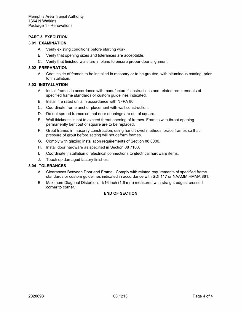
Memphis Area Transit Authority1364 N WatkinsPackage 1 - Renovations
2020698 08 1213 Page 4 of 4
PART 3 EXECUTION3.01 EXAMINATION
A. Verify existing conditions before starting work.B. Verify that opening sizes and tolerances are acceptable.C. Verify that finished walls are in plane to ensure proper door alignment.
3.02 PREPARATIONA. Coat inside of frames to be installed in masonry or to be grouted, with bituminous coating, prior
to installation.3.03 INSTALLATION
A. Install frames in accordance with manufacturer's instructions and related requirements ofspecified frame standards or custom guidelines indicated.
B. Install fire rated units in accordance with NFPA 80.C. Coordinate frame anchor placement with wall construction.D. Do not spread frames so that door openings are out of square.E. Wall thickness is not to exceed throat opening of frames. Frames with throat opening
permanently bent out of square are to be replaced.F. Grout frames in masonry construction, using hand trowel methods; brace frames so that
pressure of grout before setting will not deform frames.G. Comply with glazing installation requirements of Section 08 8000.H. Install door hardware as specified in Section 08 7100.I. Coordinate installation of electrical connections to electrical hardware items.J. Touch up damaged factory finishes.
3.04 TOLERANCESA. Clearances Between Door and Frame: Comply with related requirements of specified frame
standards or custom guidelines indicated in accordance with SDI 117 or NAAMM HMMA 861.B. Maximum Diagonal Distortion: 1/16 inch (1.6 mm) measured with straight edges, crossed
corner to corner.END OF SECTION

Memphis Area Transit Authority1364 N WatkinsPackage 1 - Renovations
2020698 08 1416 Page 1 of 4
SECTION 08 1416FLUSH WOOD DOORS
PART 1 GENERAL1.01 SECTION INCLUDES
A. Flush wood doors; flush configuration; non-rated.1.02 RELATED REQUIREMENTS
A. Section 08 1213 - Hollow Metal Frames.B. Section 08 7100 - Door Hardware.C. Section 08 8000 - Glazing.D. Section 09 9123 - Interior Painting: Field finishing of doors.
1.03 REFERENCE STANDARDSA. 16 CFR 1201 - Safety Standard for Architectural Glazing Materials; Current Edition.B. ASTM D4226 - Standard Test Methods for Impact Resistance of Rigid Poly(Vinyl Chloride)
(PVC) Building Products; 2019.C. AWI/AWMAC/WI (AWS) - Architectural Woodwork Standards; 2014, with Errata (2018).D. NFPA 80 - Standard for Fire Doors and Other Opening Protectives; 2019.E. NFPA 105 - Standard for Smoke Door Assemblies and Other Opening Protectives; 2019.F. NFPA 252 - Standard Methods of Fire Tests of Door Assemblies; 2017.G. UL 10B - Standard for Fire Tests of Door Assemblies; Current Edition, Including All Revisions.H. UL 10C - Standard for Positive Pressure Fire Tests of Door Assemblies; Current Edition,
Including All Revisions.I. UL 1784 - Standard for Air Leakage Tests of Door Assemblies; Current Edition, Including All
Revisions.J. WI (MCP) - Monitored Compliance Program (MCP); Current Edition.
1.04 SUBMITTALSA. See Section 01 3000 - Administrative Requirements, for submittal procedures.B. Product Data: Indicate door core materials and construction; veneer species, type and
characteristics.C. Shop Drawings: Show doors and frames, elevations, sizes, types, swings, undercuts, beveling,
blocking for hardware, factory machining, factory finishing, cutouts for glazing and other details.D. Samples: Submit two samples of door veneer, 8 by 8 inch (203 by 203 mm) in size illustrating
wood grain, stain color, and sheen.E. Specimen warranty.F. Warranty, executed in Owner's name.
1.05 QUALITY ASSURANCEA. Manufacturer Qualifications: Company specializing in manufacturing the products specified in
this section, with not less than three years of documented experience.1. Company with at least one project within past five years with value of woodwork within at
least 20 percent of cost of woodwork for this project.B. Installer Qualifications: Company specializing in performing work of the type specified in this
section, with not less than three years of documented experience.1.06 DELIVERY, STORAGE, AND HANDLING
A. Package, deliver and store doors in accordance with specified quality standard.

Memphis Area Transit Authority1364 N WatkinsPackage 1 - Renovations
2020698 08 1416 Page 2 of 4
B. Accept doors on site in manufacturer's packaging, and inspect for damage.C. Protect doors with resilient packaging sealed with heat shrunk plastic; do not store in damp or
wet areas or areas where sunlight might bleach veneer; seal top and bottom edges with tintedsealer if stored more than one week, and break seal on site to permit ventilation.
1.07 WARRANTYA. See Section 01 7800 - Closeout Submittals, for additional warranty requirements.B. Interior Doors: Provide manufacturer's warranty for the life of the installation.C. Include coverage for delamination of veneer, warping beyond specified installation tolerances,
defective materials, and telegraphing core construction.1. Provide for the replacement of the door as originally furnished. Manufacturer shall pay a
reasonable charge to remove defective door and replace with a new door, provided thedefect was not apparent prior to installation.
PART 2 PRODUCTS2.01 MANUFACTURERS
A. Wood Veneer Faced Doors:1. Masonite Architectural; Aspiro Select Wood Veneer Doors:
www.architectural.masonite.com/#sle.2. Oregon Door; Architectural Series: www.oregondoor.com/#sle.3. VT Industries, Inc; Heritage: www.vtindustries.com/#sle.4. Substitutions: See Section 01 6000 - PRODUCT REQUIREMENTS.
2.02 DOORS A. Doors: See drawings for locations and additional requirements.
1. Quality Level: Custom Grade, Heavy Duty performance, in accordance withAWI/AWMAC/WI (AWS).
2. Wood Veneer Faced Doors: 5-ply unless otherwise indicated.B. Interior Doors: 1-3/4 inches (44 mm) thick unless otherwise indicated; flush construction.
1. Provide solid core doors at each location.2. Fire Rated Doors: Tested to ratings as indicated on drawings in accordance with UL 10C
- Positive PressureNFPA 252 or UL 10B - Negative (Neutral) Pressure; UnderwritersLaboratories Inc. (UL) or Intertek/Warnock Hersey (WHI) labeled without any visible sealswhen door is open.
3. Smoke and Draft Control Doors: In addition to required fire rating, provide doorassemblies tested in accordance with UL 1784 with maximum air leakage of 3.0 cfm persq ft (0.01524 cu m/s/sq m) of door opening at 0.10 inch wg (24.9 Pa) pressure at bothambient and elevated temperatures for "S" label; if necessary, provide additionalgasketing or edge sealing.
4. Wood veneer facing for field opaque finish as indicated on drawings.2.03 DOOR AND PANEL CORES
A. Non-Rated Solid Core and 20 Minute Rated Doors: Type particleboard core (PC), plies andfaces as indicated.
B. Fire-Rated Doors: Mineral core type, with fire resistant composite core (FD), plies and faces asindicated above; with core blocking as required to provide adequate anchorage of hardwarewithout through-bolting.
2.04 DOOR FACINGSA. Veneer Facing for Opaque Finish: Closed grain hardwood veneer, in compliance with indicated
quality standard.B. Facing Adhesive: Type I - waterproof.

Memphis Area Transit Authority1364 N WatkinsPackage 1 - Renovations
2020698 08 1416 Page 3 of 4
2.05 DOOR CONSTRUCTIONA. Fabricate doors in accordance with door quality standard specified.B. Cores Constructed with Stiles and Rails: Structural composite lumber per WDMA; minimum 1
3/8 inch (35 mm) stiles and 5 inch (127 mm) rails.C. Provide solid blocks at lock edge for hardware reinforcement.
1. Provide solid blocking for surface mounted hardware as scheduled including but notlimited to vertical rods, exit devices and push/pull hardware.
D. Pilot holes for hinge screws are to be factory drilled at doors over 36 inches (914 mm) wide.Contractor to coordinate door hardware with door fabrication.
E. Factory machine doors for hardware other than surface-mounted hardware, in accordance withhardware requirements and dimensions.
F. Factory fit doors for frame opening dimensions identified on shop drawings, with edgeclearances in accordance with specified quality standard.1. Exception: Doors to be field finished.
G. Provide edge clearances in accordance with the quality standard specified.2.06 FINISHES - WOOD VENEER DOORS
A. Field apply finishes.B. Finish work in accordance with AWI/AWMAC/WI (AWS), Section 5 - Finishing for grade
specified and as follows:1. Opaque:
a. System - 4, Latex Acrylic, Water-based.b. Color: As selected by Architect.c. Sheen: Satin.
C. Seal door top edge with color sealer to match door facing.2.07 ACCESSORIES
A. Hollow Metal Door Frames: See Section 08 1213.B. Door Hardware: See Section 08 7100.
PART 3 EXECUTION3.01 EXAMINATION
A. Verify existing conditions before starting work.B. Verify that opening sizes and tolerances are acceptable.C. Do not install doors in frame openings that are not plumb or are out-of-tolerance for size or
alignment.3.02 INSTALLATION
A. Install doors in accordance with manufacturer's instructions and specified quality standard.1. Install fire-rated doors in accordance with NFPA 80 requirements.2. Install smoke and draft control doors in accordance with NFPA 105 requirements.
B. Factory-Finished Doors: Do not field cut or trim; if fit or clearance is not correct, replace door.C. Field-Finished Doors: Trimming to fit is acceptable.D. Adjust width of non-rated doors by cutting equally on both jamb edges.
1. Trim maximum of 3/4 inch (19 mm) off bottom edges.2. Trim fire-rated doors in strict compliance with fire rating limitations.
E. Use machine tools to cut or drill for hardware.F. Coordinate installation of doors with installation of frames and hardware.

Memphis Area Transit Authority1364 N WatkinsPackage 1 - Renovations
2020698 08 1416 Page 4 of 4
3.03 TOLERANCESA. Comply with specified quality standard for fit and clearance tolerances.B. Comply with specified quality standard for telegraphing, warp, and squareness.
3.04 ADJUSTINGA. Adjust doors for smooth and balanced door movement.B. Adjust closers for full closure.
END OF SECTION
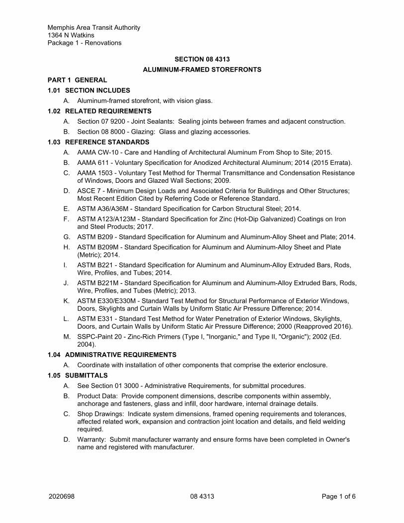
Memphis Area Transit Authority1364 N WatkinsPackage 1 - Renovations
2020698 08 4313 Page 1 of 6
SECTION 08 4313ALUMINUM-FRAMED STOREFRONTS
PART 1 GENERAL1.01 SECTION INCLUDES
A. Aluminum-framed storefront, with vision glass.1.02 RELATED REQUIREMENTS
A. Section 07 9200 - Joint Sealants: Sealing joints between frames and adjacent construction.B. Section 08 8000 - Glazing: Glass and glazing accessories.
1.03 REFERENCE STANDARDSA. AAMA CW-10 - Care and Handling of Architectural Aluminum From Shop to Site; 2015.B. AAMA 611 - Voluntary Specification for Anodized Architectural Aluminum; 2014 (2015 Errata).C. AAMA 1503 - Voluntary Test Method for Thermal Transmittance and Condensation Resistance
of Windows, Doors and Glazed Wall Sections; 2009.D. ASCE 7 - Minimum Design Loads and Associated Criteria for Buildings and Other Structures;
Most Recent Edition Cited by Referring Code or Reference Standard.E. ASTM A36/A36M - Standard Specification for Carbon Structural Steel; 2014.F. ASTM A123/A123M - Standard Specification for Zinc (Hot-Dip Galvanized) Coatings on Iron
and Steel Products; 2017.G. ASTM B209 - Standard Specification for Aluminum and Aluminum-Alloy Sheet and Plate; 2014.H. ASTM B209M - Standard Specification for Aluminum and Aluminum-Alloy Sheet and Plate
(Metric); 2014.I. ASTM B221 - Standard Specification for Aluminum and Aluminum-Alloy Extruded Bars, Rods,
Wire, Profiles, and Tubes; 2014.J. ASTM B221M - Standard Specification for Aluminum and Aluminum-Alloy Extruded Bars, Rods,
Wire, Profiles, and Tubes (Metric); 2013.K. ASTM E330/E330M - Standard Test Method for Structural Performance of Exterior Windows,
Doors, Skylights and Curtain Walls by Uniform Static Air Pressure Difference; 2014.L. ASTM E331 - Standard Test Method for Water Penetration of Exterior Windows, Skylights,
Doors, and Curtain Walls by Uniform Static Air Pressure Difference; 2000 (Reapproved 2016).M. SSPC-Paint 20 - Zinc-Rich Primers (Type I, "Inorganic," and Type II, "Organic"); 2002 (Ed.
2004).1.04 ADMINISTRATIVE REQUIREMENTS
A. Coordinate with installation of other components that comprise the exterior enclosure.1.05 SUBMITTALS
A. See Section 01 3000 - Administrative Requirements, for submittal procedures.B. Product Data: Provide component dimensions, describe components within assembly,
anchorage and fasteners, glass and infill, door hardware, internal drainage details.C. Shop Drawings: Indicate system dimensions, framed opening requirements and tolerances,
affected related work, expansion and contraction joint location and details, and field weldingrequired.
D. Warranty: Submit manufacturer warranty and ensure forms have been completed in Owner'sname and registered with manufacturer.

Memphis Area Transit Authority1364 N WatkinsPackage 1 - Renovations
2020698 08 4313 Page 2 of 6
1.06 QUALITY ASSURANCEA. Designer Qualifications: Design structural support framing components under direct
supervision of a Professional Structural Engineer experienced in design of this Work andlicensed in the State in which the Project is located.
B. Manufacturer Qualifications: Company specializing in performing work of type specified andwith at least three years of documented experience.
1.07 DELIVERY, STORAGE, AND HANDLINGA. Handle products of this section in accordance with AAMA CW-10.B. Protect finished aluminum surfaces with strippable coating. Do not use adhesive papers or
sprayed coatings that bond to aluminum when exposed to sunlight or weather.1.08 FIELD CONDITIONS
A. Do not install sealants when ambient temperature is less than 40 degrees F (5 degrees C). Maintain this minimum temperature during and 48 hours after installation.
1.09 WARRANTYA. See Section 01 7800 - Closeout Submittals, for additional warranty requirements.B. Correct defective Work within a five year period after Date of Substantial Completion.C. Provide 7 year manufacturer warranty against failure of glass seal on insulating glass units,
including interpane dusting or misting. Include provision for replacement of failed units.D. Provide five year manufacturer warranty against excessive degradation of exterior finish.
Include provision for replacement of units with excessive fading, chalking, or flaking.PART 2 PRODUCTS2.01 BASIS OF DESIGN -- FRAMING FOR EXTERIOR INSULATING GLAZING
A. Center-Set Style, Thermally-Broken:1. Basis of Design: Kawneer North America, Trfab VG 451T, Center-Set:
www.kawneer.com.2. Vertical Mullion Dimensions: 2 inches wide by 4-1/2 inches deep (51 mm wide by 114
mm deep).B. Other Manufacturers: Provide either the product identified as "Basis of Design" or an
equivalent product of one of the manufacturers listed below:1. EFCO, a Pella Company: www.efcocorp.com.2. Trulite Glass & Aluminum Solutions, LLC: www.trulite.com/#sle.
C. Substitutions: See Section 01 6000 - PRODUCT REQUIREMENTS.1. For any product not identified as "Basis of Design", submit information as specified for
substitutions.2.02 ALUMINUM-FRAMED STOREFRONT
A. Aluminum-Framed Storefront: Factory fabricated, factory finished aluminum framing memberswith infill, and related flashings, anchorage and attachment devices.1. Unitized, shop assembly.2. Glazing Rabbet Exterior: For 1 inch (25 mm) insulating glazing.3. Finish: Class I color anodized.
a. Factory finish all surfaces that will be exposed in completed assemblies.b. Coat concealed metal surfaces that will be in contact with cementitious materials or
dissimilar metals with bituminous paint.c. Finish Color: Dark bronze.
4. Fabrication: Joints and corners flush, hairline, and weatherproof, accurately fitted andsecured; prepared to receive anchors and hardware; fasteners and attachmentsconcealed from view; reinforced as required for imposed loads.

Memphis Area Transit Authority1364 N WatkinsPackage 1 - Renovations
2020698 08 4313 Page 3 of 6
5. Construction: Eliminate noises caused by wind and thermal movement, prevent vibrationharmonics, and prevent "stack effect" in internal spaces.
6. System Internal Drainage: Drain to the exterior by means of a weep drainage networkany water entering joints, condensation occurring in glazing channel, and migratingmoisture occurring within system.
7. Expansion/Contraction: Provide for expansion and contraction within system componentscaused by cycling temperature range of 170 degrees F (95 degrees C) over a 12 hourperiod without causing detrimental effect to system components, anchorages, and otherbuilding elements.
8. Movement: Allow for movement between storefront and adjacent construction, withoutdamage to components or deterioration of seals.
9. Perimeter Clearance: Minimize space between framing members and adjacentconstruction while allowing expected movement.
B. Performance Requirements1. Wind Loads: Design and size components to withstand the specified load requirements
without damage or permanent set, when tested in accordance with ASTM E330/E330M,using loads 1.5 times the design wind loads and 10 second duration of maximum load.
2. Exterior Glazing:a. Design Wind Loads: Comply with requirements of ASCE 7.
3. Member Deflection: Limit member deflection to flexure limit of glass in any direction, withfull recovery of glazing materials.
4. Reinforce framing members at door openings to hold latch bolt in place when door isimpacted by forced entry loads. Door is to resist a 2,500 pound load.
5. Water Penetration Resistance on Manufactured Assembly: No uncontrolled water oninterior face, when tested in accordance with ASTM E331 at pressure differential of 10 psf(480 Pa).
6. Air Leakage: 0.06 cfm/sq ft (0.3 L/sec sq m) maximum leakage of storefront wall areawhen tested in accordance with ASTM E283/E283M at 6.27 psf (300 Pa) pressuredifference.
7. Condensation Resistance Factor of Framing: 50, minimum, measured in accordance withAAMA 1503.
2.03 COMPONENTSA. Aluminum Framing Members: Tubular aluminum sections, thermally broken with interior
section insulated from exterior, drainage holes and internal weep drainage system.1. Structurally Reinforced Members: Extruded aluminum with internal reinforcement of
structural steel member.B. Glazing: As specified in Section 08 8000.
1. Exterior Framing: Type IG-1.2.04 MATERIALS
A. Extruded Aluminum: 6063 alloy, T5 temper, ASTM B221 (ASTM B221M).B. Sheet Aluminum: ASTM B209 (ASTM B209M).C. Structural Steel Sections: ASTM A36/A36M; galvanized in accordance with requirements of
ASTM A123/A123M.D. Structural Supporting Anchors Attached to Structural Steel: Design for welded attachment.E. Thermal Barrier: Two part, chemical curing, high density polyurethane.F. Fasteners: Zinc plated steel concealed fasteners; Hardened aluminum alloys or AISI 300
series stainless steel exposed fasteners, countersunk, finish to match aluminum color.1. No exposed fasteners except where unavoidable. Where fasteners are exposed use
philips head countersunk fasteners with finish to match framing system.

Memphis Area Transit Authority1364 N WatkinsPackage 1 - Renovations
2020698 08 4313 Page 4 of 6
G. Exposed Flashings: Aluminum sheet, 20 gauge, 0.032 inch (0.81 mm) minimum thickness;finish to match framing members.
H. Concealed Flashings: Sheet aluminum, 26 gauge, 0.017 inch (0.43 mm) minimum thickness.I. Sill Flashing Sealant: Elastomeric, silicone or polyurethane, compatible with flashing material.J. Sealant for Setting Thresholds: Non-curing butyl type.K. Sill Flashing: Extruded High Performance flashing designed to receive sill framing. Match
construction and finish of storefront framing system. Provide at all sill members.L. Perimeter Sealant: Silicone as specified in Section 07 9000.M. Glazing Gaskets: EPDM.N. Glazing Accessories: As specified in Section 08 8000.O. Coordinate installation of glass with glazing manufacturer.P. Touch-Up Primer for Galvanized Steel Surfaces: SSPC-Paint 20, zinc rich.
2.05 FINISHESA. Class I Color Anodized Finish: AAMA 611 AA-M12C22A42 Integrally colored anodic coating
not less than 0.7 mils (0.018 mm) thick.B. Color: Dark bronze.C. Touch-Up Materials: As recommended by coating manufacturer for field application.
PART 3 EXECUTION3.01 EXAMINATION
A. Verify dimensions, tolerances, and method of attachment with other work.B. Verify that wall openings and adjoining air and vapor seal materials are ready to receive work
of this section.3.02 INSTALLATION
A. Install wall system in accordance with manufacturer's instructions.B. Attach to structure to permit sufficient adjustment to accommodate construction tolerances and
other irregularities.C. Provide attachment that allows for thermal movement.D. Provide alignment attachments and shims to permanently fasten system to building structure.E. Align assembly plumb and level, free of warp or twist. Maintain assembly dimensional
tolerances, aligning with adjacent work.F. Provide thermal isolation where components penetrate or disrupt building insulation.G. Install sill flashings. Turn up ends and edges; seal to adjacent work to form water tight dam.H. Where fasteners penetrate sill flashings, make watertight by seating and sealing fastener
heads to sill flashing.I. Pack fibrous insulation in shim spaces at perimeter of assembly to maintain continuity of
thermal barrier.J. Install glass in accordance with Section 08 8000, using glazing method required to achieve
performance criteria.K. Touch-up minor damage to factory applied finish; replace components that cannot be
satisfactorily repaired.3.03 TOLERANCES
A. Maximum Variation from Plumb: 0.06 inch per 3 feet (1.5 mm per m) non-cumulative or 0.06inch per 10 feet (1.5 mm per 3 m), whichever is less.

Memphis Area Transit Authority1364 N WatkinsPackage 1 - Renovations
2020698 08 4313 Page 5 of 6
B. Maximum Misalignment of Two Adjoining Members Abutting in Plane: 1/32 inch (0.8 mm).3.04 CLEANING
A. Remove protective material from pre-finished aluminum surfaces.B. Wash down surfaces with a solution of mild detergent in warm water, applied with soft, clean
wiping cloths, and take care to remove dirt from corners and to wipe surfaces clean.3.05 PROTECTION
A. Protect installed products from damage until Date of Substantial Completion.END OF SECTION

Memphis Area Transit Authority1364 N WatkinsPackage 1 - Renovations
2020698 08 4313 Page 6 of 6

Memphis Area Transit Authority1364 N WatkinsPackage 1 - Renovations
2020698 08 7100 Page 1 of 8
SECTION 08 7100DOOR HARDWARE
PART 1 GENERAL1.01 SECTION INCLUDES
A. Hardware for wood doors.B. Hardware for fire-rated doors.C. Weatherstripping and gasketing.
1.02 RELATED REQUIREMENTSA. Section 08 1213 - Hollow Metal Frames.B. Section 08 1416 - Flush Wood Doors.C. Section 08 4313 - ALUMINUM-FRAMED STOREFRONTS: Door hardware, except as noted in
section.1.03 REFERENCE STANDARDS
A. ADA Standards - Americans with Disabilities Act (ADA) Standards for Accessible Design; 2010.B. BHMA (CPD) - Certified Products Directory; Current Edition.C. BHMA A156.1 - American National Standard for Butts and Hinges; 2016.D. BHMA A156.2 - American National Standard for Bored and Preassembled Locks & Latches;
2017.E. BHMA A156.4 - American National Standard for Door Controls - Closers; 2013.F. BHMA A156.6 - American National Standard for Architectural Door Trim; 2015.G. BHMA A156.8 - American National Standard for Door Controls - Overhead Stops and Holders;
2015.H. BHMA A156.16 - American National Standard for Auxiliary Hardware; 2018.I. BHMA A156.18 - American National Standard for Materials and Finishes; 2016.J. BHMA A156.22 - American National Standard for Door Gasketing and Edge Seal Systems
Sponsor; 2017.K. BHMA A156.28 - American National Standard for Recommended Practices for Mechanical
Keying Systems; 2018.L. BHMA A156.115W - American National Standard for Hardware Preparation in Wood Doors
with Wood or Steel Frames; 2006.M. DHI (KSN) - Keying Systems and Nomenclature; 1989.N. DHI WDHS.3 - Recommended Locations for Architectural Hardware for Flush Wood Doors;
1993; also in WDHS-1/WDHS-5 Series, 1996.O. ICC A117.1 - Accessible and Usable Buildings and Facilities; 2017.P. ITS (DIR) - Directory of Listed Products; current edition.Q. NFPA 80 - Standard for Fire Doors and Other Opening Protectives; 2019.R. NFPA 101 - Life Safety Code; Most Recent Edition Adopted by Authority Having Jurisdiction,
Including All Applicable Amendments and Supplements.S. NFPA 105 - Standard for Smoke Door Assemblies and Other Opening Protectives; 2019.T. NFPA 252 - Standard Methods of Fire Tests of Door Assemblies; 2017.U. UL (DIR) - Online Certifications Directory; Current Edition.V. UL 10C - Standard for Positive Pressure Fire Tests of Door Assemblies; Current Edition,
Including All Revisions.

Memphis Area Transit Authority1364 N WatkinsPackage 1 - Renovations
2020698 08 7100 Page 2 of 8
W. UL 1784 - Standard for Air Leakage Tests of Door Assemblies; Current Edition, Including AllRevisions.
1.04 ADMINISTRATIVE REQUIREMENTSA. Coordinate the manufacture, fabrication, and installation of products that door hardware is
installed on.B. Sequence installation to ensure utility connections are achieved in an orderly and expeditious
manner.C. Furnish templates for door and frame preparation to manufacturers and fabricators of products
requiring internal reinforcement for door hardware.D. Keying Requirements Meeting:
1. Schedule meeting at project site prior to Contractor occupancy.2. Attendance Required:
a. Contractor.b. Owner.c. Architect.
3. Agenda:a. Establish keying requirements.b. Verify locksets and locking hardware are functionally correct for project requirements.c. Verify that keying and programming complies with project requirements.d. Establish keying submittal schedule and update requirements.
4. Incorporate "Keying Requirements Meeting" decisions into keying submittal upon reviewof door hardware keying system including, but not limited to, the following:a. Key control system requirements.b. Schematic diagram of preliminary key system.c. Flow of traffic and extent of security required.
5. Record minutes and distribute copies within two days after meeting to participants, withtwo copies to Architect, Owner, participants, and those affected by decisions made.
6. Deliver established keying requirements to manufacturers.1.05 SUBMITTALS
A. See Section 01 3000 - Administrative Requirements, for submittal procedures.B. Product Data: Manufacturer's catalog literature for each type of hardware, marked to clearly
show products to be furnished for this project, and includes construction details, materialdescriptions, finishes, and dimensions and profiles of individual components.
C. Shop Drawings - Door Hardware Schedule: Submit detailed listing that includes each item ofhardware to be installed on each door. Use door numbering scheme as included in ContractDocuments.1. Prepared by or under supervision of Architectural Hardware Consultant (AHC).2. Provide complete description for each door listed.
D. Samples for Verification:1. Submit minimum size of 2 by 4 inch (51 by 102 mm) for sheet samples, and minimum
length of 4 inch (102 mm) for other products.2. Submit one (1) sample of hinge, lockset, and closer illustrating style, color, and finish.3. Return full-size samples to be incorporated into this Work.4. Submit product description with samples.
E. Manufacturer's Installation Instructions: Indicate special procedures and perimeter conditionsrequiring special attention.
F. Warranty: Submit manufacturer's warranty and ensure that forms have been completed inOwner's name and registered with manufacturer.
Memphis Area Transit Authority1364 N WatkinsPackage 1 - Renovations
2020698 08 7100 Page 3 of 8
1.06 QUALITY ASSURANCEA. Manufacturer Qualifications: Company specializing in manufacturing products specified in this
section with minimum three years of documented experience.B. Installer Qualifications: Company specializing in performing work of the type specified for
commercial door hardware with at least three years of documented experience.C. Supplier Qualifications: Company with certified Architectural Hardware Consultant (AHC) to
assist in work of this section.1.07 DELIVERY, STORAGE, AND HANDLING
A. Package hardware items individually; label and identify each package with door opening codeto match door hardware schedule.
1.08 WARRANTYA. See Section 01 7800 - Closeout Submittals, for additional warranty requirements.B. Warranty against defects in material and workmanship for period indicated, from Date of
Substantial Completion.1. Closers: Ten years, minimum.2. Locksets and Cylinders: Ten, minimum.3. Other Hardware: Two years, minimum.
PART 2 PRODUCTS2.01 DESIGN AND PERFORMANCE CRITERIA
A. Hardware Selection and Schedule: Architectural Hardware Consultant is to select hardwareand develop Hardware Schedule as required to make doors operable based on functionsindicated on drawings.1. Key hardware to match existing keying system.
B. Provide specified door hardware as required to make doors fully functional, compliant withapplicable codes, and secure to extent indicated.
C. Provide individual items of single type, of same model, and by same manufacturer.D. Provide door hardware products that comply with the following requirements:
1. Applicable provisions of local codes.2. Accessibility: ADA Standards and ICC A117.1.3. Applicable provisions of NFPA 101.4. Fire-Rated Doors: NFPA 80, listed and labeled by qualified testing agency for fire
protection ratings indicated, based on testing at positive pressure in accordance withNFPA 252 or UL 10C.
5. Hardware on Fire-Rated Doors: Listed and classified by UL (DIR), ITS (DIR), testing firmacceptable to authorities having jurisdiction, or _____ as suitable for application indicated.
6. Hardware for Smoke and Draft Control Doors: Provide door hardware that complies withlocal codes, and requirements of assemblies tested in accordance with UL 1784.a. Air Leakage Rate: Tested in accordance with UL 1784, with air leakage rate not to
exceed 3.0 cfm/sf (0.01524 cu m/sec/sq m) of door opening at 0.10 inch (24.9 Pa) ofwater for both ambient and elevated temperature tests.
7. Listed and certified compliant with specified standards by BHMA (CPD).8. Auxiliary Hardware: BHMA A156.16.9. Hardware Preparation for Wood Doors with Wood or Steel Frames: BHMA A156.115W.10. Products Requiring Electrical Connection: Listed and classified by UL (DIR) as suitable
for the purpose specified.E. Lock Function: Provide lock and latch function numbers and descriptions of manufacturer's
series. Refer to Door Hardware Schedule.F. Fasteners:
Memphis Area Transit Authority1364 N WatkinsPackage 1 - Renovations
2020698 08 7100 Page 4 of 8
1. Provide fasteners of proper type, size, quantity, and finish that comply with commerciallyrecognized standards for proposed applications.a. Aluminum fasteners are not permitted.b. Provide phillips flat-head screws with heads finished to match door surface hardware
unless otherwise indicated.2. Provide machine screws for attachment to reinforced hollow metal and aluminum frames.
a. Self-drilling (Tek) type screws are not permitted.3. Provide stainless steel machine screws and lead expansion shields for concrete and
masonry substrates.4. Provide wall grip inserts for hollow wall construction.5. Provide spacers or sex bolts with sleeves for through bolting of hollow metal doors and
frames.6. Fire-Rated Applications: Comply with NFPA 80.
a. Provide wood or machine screws for hinges mortised to doors or frames, strike platesto frames, and closers to doors and frames.
b. Provide steel through bolts for attachment of surface mounted closers, hinges, or exitdevices to door panels unless proper door blocking is provided.
2.02 HINGESA. Manufacturers:
1. McKinney; an Assa Abloy Group company; TA2714 - 4.5 inches x 4.5 inches andT4A3786-5 inches x 4.5" inches: www.assaabloydss.com.
2. Hager Companies; BB1279 - 4.5 inches x 4.5 inches and BB1168-5 inches x 4.5 inches: www.hagerco.com/#sle.
3. Stanley, dormakaba Group; FBB179 - 4.5 inches x 4.5 inches and FBB168-5 inches x4 .5inches: www.stanleyhardwarefordoors.com/#sle.
4. Substitutions: See Section 01 6000 - PRODUCT REQUIREMENTS.B. Hinges: Comply with BHMA A156.1, Grade 1.
1. Provide hinges on every swinging door.2. Provide five-knuckle full mortise butt hinges unless otherwise indicated.3. Provide ball-bearing hinges at each door.4. Provide following quantity of butt hinges for each door:
a. Doors up to 60 inches (1.5 m) High: Two hinges.b. Doors From 60 inches (1.5 m) High up to 90 inches (2.3 m) High: Three hinges.c. Doors 90 inches (2.3 m) High up to 120 inches (3 m) High: Four hinges.d. Dutch Doors: Two hinges each leaf.
2.03 LOCK CYLINDERSA. Manufacturers:
1. Basis of Design: Match existing.2. Substitutions: See Section 01 6000 - PRODUCT REQUIREMENTS.
B. Lock Cylinders: Provide key access on outside of each lock, unless otherwise indicated.1. Provide cylinders from same manufacturer as locking device.2. Provide cams and/or tailpieces as required for locking devices.
2.04 CYLINDRICAL LOCKSA. Manufacturers:
1. Basis of Design: Sargent; 10 Line Cylindrical Lever Locks, with P Lever:www.asaabloyss.com..
2. Corbin Russwin; an Assa Abloy Group company: www.assaabloydss.com/#sle.3. Hager Companies: www.hagerco.com/#sle.4. Schlage, an Allegion brand: www.allegion.com/us/#sle.5. Substitutions: See Section 01 6000 - PRODUCT REQUIREMENTS.

Memphis Area Transit Authority1364 N WatkinsPackage 1 - Renovations
2020698 08 7100 Page 5 of 8
B. Cylindrical Locks (Bored): Comply with BHMA A156.2, Grade 1, 4000 Series.1. Bored Hole: 2-1/8 inch (54 mm) diameter.2. Latchbolt Throw: 1/2 inch (12.7 mm), minimum.3. Backset: 2-3/4 inch (70 mm) unless otherwise indicated.4. Strikes: Provide manufacturer's standard strike for each latchset or lockset with strike box
and curved lip extending to protect frame in compliance with indicated requirements.a. Finish: To match lock or latch.b. Flat-Lip Strikes: Provide for locks with three piece antifriction latchbolts as
recommended by manufacturer.5. See drawings for lockset function.
2.05 CLOSERSA. Manufacturers; Surface Mounted:
1. Basis of Design: Corbin Russwin - DC8000 Series, Norton Door Controls - 9500 Series,Sargent - 281 Series: www.assaabloydss.com.
2. Hager Companies: www.hagerco.com/#sle.3. LCN, an Allegion brand: www.allegion.com/us/#sle.4. Substitutions: See Section 01 6000 - PRODUCT REQUIREMENTS.
B. Closers: Comply with BHMA A156.4, Grade 1.1. Type: Surface mounted to door.2. Provide door closer on each fire-rated and smoke-rated door.3. Provide door closer where indicated on door opening schedule.
2.06 OVERHEAD STOPS AND HOLDERSA. Overhead Holders:
1. Sargent: 690 Series.2. Rixson: 1 and 1ADJ Series.
B. Manufacturers:1. Rixson or Sargent; an Assa Abloy Group company: www.assaabloydss.com.
a. Rixson - 1 and 1ADJ Series, Sargent - 690 Series.C. Overhead Stops and Holders (Door Checks): Comply with BHMA A156.8, Grade 1.
1. Provide stop for every swinging door, unless otherwise indicated.2.07 PROTECTION PLATES
A. Manufacturers:1. Rockwood or McKinney; an Assa Abloy Group company: www.assaabloydss.com.2. Hiawatha, Inc, an Activar Construction Products Group company:
www.activarcpg.com/hiawatha/#sle.3. Trimco: www.trimcohardware.com.4. Substitutions: See Section 01 6000 - PRODUCT REQUIREMENTS.
B. Protection Plates: Comply with BHMA A156.6.C. Metal Properties: Aluminum.
1. Metal, Standard Duty: Thickness 0.05 inch (1.27 mm), minimum.D. Edges: Beveled, on four sides unless otherwise indicated.E. Fasteners: Countersunk screw fasteners.F. Provide clear anti-microbial coating that is silver ion-based.
2.08 WEATHERSTRIPPING AND GASKETINGA. Manufacturers:
1. Pemko; an Assa Abloy Group company: www.assaabloydss.com/#sle.2. Hager Companies: www.hagerco.com/#sle.

Memphis Area Transit Authority1364 N WatkinsPackage 1 - Renovations
2020698 08 7100 Page 6 of 8
3. National Guard Products, Inc: www.ngpinc.com/#sle.4. Substitutions: See Section 01 6000 - PRODUCT REQUIREMENTS.
B. Weatherstripping and Gasketing: Comply with BHMA A156.22.1. Head and Jamb Type: Adjustable.2. Door Sweep Type: Encased in retainer.3. Material: Aluminum, with brush weatherstripping.4. Provide gasketing for smoke and draft control doors that complies with local codes,
requirements of assemblies tested in accordance with UL 1784.2.09 KEY CONTROL SYSTEMS
A. Key Control Systems: Comply with guidelines of BHMA A156.28.1. Provide keying information in compliance with DHI (KSN) standards.2. Keying: Grand master keyed.3. Supply keys in following quantities:
a. 4 Grand Master keys.b. 1 each Great Grand Master keys.c. 15 each Construction keys.d. 2 each Change keys for each keyed core.
4. Key Management System: For each keyed lock on project, provide one set ofconsecutively numbered duplicate key tags with hanging hole and snap catch.
5. Security Key Tags: For each keyed lock on project, provide one set of matching key tagsfor permanent attachment to one key of each set.
6. Provide key collection envelopes, receipt cards, and index cards in quantity suitable tomanage number of keys.
7. Deliver keys with identifying tags to Owner by security shipment direct from hardwaresupplier.
8. Permanent Keys and Cores: Stamped with applicable key marking for identification. Donot include actual key cuts within visual key control marks or codes. Stamp permanentkeys "Do Not Duplicate."
2.10 FINISHESA. Finishes: Provide door hardware of same finish, unless otherwise indicated.
1. Primary Finish: 625; bright chromium plated over nickel, with brass or bronze basematerial (former US equivalent US26); BHMA A156.18.
2. Secondary Finish: 626; satin chromium plated over nickel, with brass or bronze basematerial (former US equivalent US26D); BHMA A156.18.a. Use secondary finish in kitchens, bathrooms, and other spaces containing chrome or
stainless steel finished appliances, fittings, and equipment; provide primary finish onone side of door and secondary finish on other side if necessary.
PART 3 EXECUTION3.01 EXAMINATION
A. Verify that doors and frames are ready to receive this work; labeled, fire-rated doors andframes are properly installed, and dimensions are as indicated on shop drawings.
B. Verify that electric power is available to power operated devices and of correct characteristics.3.02 INSTALLATION
A. Install hardware in accordance with manufacturer's instructions and applicable codes.B. Install hardware on fire-rated doors and frames in accordance with applicable codes and NFPA
80.C. Install hardware for smoke and draft control doors in accordance with NFPA 105.D. Use templates provided by hardware item manufacturer.

Memphis Area Transit Authority1364 N WatkinsPackage 1 - Renovations
2020698 08 7100 Page 7 of 8
E. Do not install surface mounted items until application of finishes to substrate are fullycompleted.
F. Door Hardware Mounting Heights: Distance from finished floor to center line of hardware item. As indicated in following list; unless noted otherwise in Door Hardware Schedule or ondrawings.1. For Steel Door Frames: Refer to Section 08 1213.2. For Wood Doors: Install in compliance with DHI WDHS.3 recommendations.3. Mounting heights in compliance with ADA Standards:
G. Set exterior door thresholds with full-width bead of elastomeric sealant at each point of contactwith floor providing a continuous weather seal; anchor thresholds with stainless steelcountersunk screws.
3.03 FIELD QUALITY CONTROLA. Perform field inspection and testing under provisions of Section 01 4000 - Quality
Requirements.B. Provide an Architectural Hardware Consultant (AHC) to inspect installation and certify that
hardware and installation has been furnished and installed in accordance with manufacturer'sinstructions and as specified.
3.04 ADJUSTINGA. Adjust work under provisions of Section 01 7000 - Execution and Closeout Requirements.B. Adjust hardware for smooth operation.C. Adjust gasketing for complete, continuous seal; replace if unable to make complete seal.
3.05 CLEANINGA. Clean finished hardware in accordance with manufacturer's written instructions after final
adjustments have been made.B. Clean adjacent surfaces soiled by hardware installation.C. Replace items that cannot be cleaned to manufacturer's level of finish quality at no additional
cost.3.06 PROTECTION
A. Protect finished Work under provisions of Section 01 7000 - Execution and CloseoutRequirements.
B. Do not permit adjacent work to damage hardware or finish.END OF SECTION

Memphis Area Transit Authority1364 N WatkinsPackage 1 - Renovations
2020698 08 7100 Page 8 of 8

Memphis Area Transit Authority1364 N WatkinsPackage 1 - Renovations
2020698 08 8000 Page 1 of 6
SECTION 08 8000GLAZING
PART 1 GENERAL1.01 SECTION INCLUDES
A. Insulating glass units.B. Glazing units.C. Plastic films.D. Glazing compounds.
1.02 RELATED REQUIREMENTSA. Section 07 9200 - Joint Sealants: Sealants for other than glazing purposes.B. Section 08 4313 - ALUMINUM-FRAMED STOREFRONTS: Glazing provided as part of
storefront assembly.1.03 REFERENCE STANDARDS
A. 16 CFR 1201 - Safety Standard for Architectural Glazing Materials; Current Edition.B. ANSI Z97.1 - American National Standard for Safety Glazing Materials Used in Buildings -
Safety Performance Specifications and Methods of Test; 2015.C. ASCE 7 - Minimum Design Loads and Associated Criteria for Buildings and Other Structures;
Most Recent Edition Cited by Referring Code or Reference Standard.D. ASTM C864 - Standard Specification for Dense Elastomeric Compression Seal Gaskets,
Setting Blocks, and Spacers; 2005 (Reapproved 2015).E. ASTM C920 - Standard Specification for Elastomeric Joint Sealants; 2018.F. ASTM C1048 - Standard Specification for Heat-Strengthened and Fully Tempered Flat Glass;
2018.G. ASTM C1193 - Standard Guide for Use of Joint Sealants; 2016.H. ASTM C1376 - Standard Specification for Pyrolytic and Vacuum Deposition Coatings on Flat
Glass; 2015.I. ASTM E1300 - Standard Practice for Determining Load Resistance of Glass in Buildings; 2016.J. ASTM E2190 - Standard Specification for Insulating Glass Unit Performance and Evaluation;
2010.K. GANA (GM) - GANA Glazing Manual; 2008.L. GANA (SM) - GANA Sealant Manual; 2008.M. NFRC 100 - Procedure for Determining Fenestration Product U-factors; 2017.N. NFRC 200 - Procedure for Determining Fenestration Product Solar Heat Gain Coefficient and
Visible Transmittance at Normal Incidence; 2014, with Errata (2017).O. NFRC 300 - Test Method for Determining the Solar Optical Properties of Glazing Materials and
Systems; 2017.1.04 ADMINISTRATIVE REQUIREMENTS
A. Preinstallation Meeting: Convene a preinstallation meeting one week before starting work ofthis section; require attendance by each of the affected installers.
1.05 SUBMITTALSA. See Section 01 3000 - Administrative Requirements, for submittal procedures.B. Product Data on Glazing Unit Glazing Types: Provide structural, physical and environmental
characteristics, size limitations, special handling and installation requirements.

Memphis Area Transit Authority1364 N WatkinsPackage 1 - Renovations
2020698 08 8000 Page 2 of 6
C. Product Data on Glazing Compounds and Accessories: Provide chemical, functional, andenvironmental characteristics, limitations, special application requirements, and identifyavailable colors.
D. Certificate: Certify that products of this section meet or exceed specified requirements.E. Warranty Documentation: Submit manufacturer warranty and ensure that forms have been
completed in Owner's name and registered with manufacturer.1.06 QUALITY ASSURANCE
A. Perform Work in accordance with GANA (GM) and GANA (SM) for glazing installation methods.
B. Manufacturer Qualifications: Company specializing in manufacturing the products specified inthis section with minimum three years of documented experience.
C. Installer Qualifications: Company specializing in performing work of the type specified and withat least three years documented experience.
1.07 FIELD CONDITIONSA. Do not install glazing when ambient temperature is less than 40 degrees F (4 degrees C).B. Maintain minimum ambient temperature before, during and 24 hours after installation of glazing
compounds.1.08 WARRANTY
A. See Section 01 7800 - Closeout Submittals, for additional warranty requirements.B. Insulating Glass Units: Provide a seven (7) year manufacturer warranty to include coverage for
seal failure, interpane dusting or misting, including replacement of failed units.PART 2 PRODUCTS2.01 MANUFACTURERS
A. Glass Fabricators:1. JE Berkowitz, LP: www.jeberkowitz.com.2. Trulite Glass & Aluminum Solutions, LLC: www.trulite.com.3. Viracon, Inc: www.viracon.com.4. Wholesale Glass Distributors, Inc.: www.wgdmemphis.com.5. Substitutions: See Section 01 6000 - PRODUCT REQUIREMENTS.
B. Float Glass Manufacturers:1. AGC Glass Company North America, Inc: www.us.agc.com.2. Cardinal Glass Industries: www.cardinalcorp.com.3. Guardian Industries Corp: www.sunguardglass.com.4. Pilkington North America Inc: www.pilkington.com/na.5. PPG Industries, Inc: www.ppgideascapes.com.6. Substitutions: See Section 01 6000 - PRODUCT REQUIREMENTS.
2.02 PERFORMANCE REQUIREMENTS - EXTERIOR GLAZING ASSEMBLIESA. Provide type and thickness of exterior glazing assemblies to support assembly dead loads, and
to withstand live loads caused by positive and negative wind pressure acting normal to plane ofglass.1. Design Pressure: Calculated in accordance with ASCE 7.2. Comply with ASTM E1300 for design load resistance of glass type, thickness, dimensions,
and maximum lateral deflection of supported glass.3. Seismic Loads: Design and size glazing components to withstand seismic loads and
sway displacement in accordance with the requirements of ASCE 7.4. Provide glass edge support system sufficiently stiff to limit the lateral deflection of
supported glass edges to less than 1/175 of their lengths under specified design load.

Memphis Area Transit Authority1364 N WatkinsPackage 1 - Renovations
2020698 08 8000 Page 3 of 6
5. Glass thicknesses listed are minimum.B. Provide tempered glass in hazardous locations per the requirements of the International
Building Code, 2012.C. Vapor Retarder and Air Barrier Seals: Provide completed assemblies that maintain continuity
of building enclosure vapor retarder and air barrier.1. In conjunction with vapor retarder and joint sealer materials described in other sections.
D. Thermal and Optical Performance: Provide exterior glazing products with performanceproperties as indicated. Performance properties are in accordance with manufacturer'spublished data as determined with the following procedures and/or test methods:1. Center of Glass U-Value: Comply with NFRC 100 using Lawrence Berkeley National
Laboratory (LBNL) WINDOW 6.3 computer program.2. Center of Glass Solar Heat Gain Coefficient (SHGC): Comply with NFRC 200 using
Lawrence Berkeley National Laboratory (LBNL) WINDOW 6.3 computer program.3. Solar Optical Properties: Comply with NFRC 300 test method.
2.03 GLASS MATERIALSA. Float Glass: Provide float glass based glazing unless otherwise indicated.
1. Kind HS - Heat-Strengthened Type: Complies with ASTM C1048.2. Fully Tempered Safety Glass: Complies with ANSI Z97.1 or 16 CFR 1201 criteria for
safety glazing used in hazardous locations.2.04 INSULATING GLASS UNITS
A. Manufacturers:1. Glass: Any of the manufacturers specified for float glass.
B. Insulating Glass Units: Types as indicated.1. Durability: Certified by an independent testing agency to comply with ASTM E2190.2. Coated Glass: Comply with requirements of ASTM C1376 for pyrolytic (hard-coat) or
magnetic sputter vapor deposition (soft-coat) type coatings on flat glass; coated visionglass, Kind CV; coated overhead glass, Kind CO; or coated spandrel glass, Kind CS.
3. Metal Edge Spacers: Aluminum, bent and soldered corners.4. Spacer Color: Black.5. Edge Seal:
a. Dual-Sealed System: Provide polyisobutylene sealant as primary seal appliedbetween spacer and glass panes, and silicone, polysulfide, or polyurethane sealantas secondary seal applied around perimeter.
6. Color: Black.7. Purge interpane space with dry air, hermetically sealed.8. Capillary Tubes: Provide tubes from air space for insulating glass units without inert type
gas that have a change of altitude greater than 2500 feet (762 m) between point offabrication and point of installation to permit pressure equalization of air space.a. Capillary Tubes: Tubes to remain open and be of length and material type in
accordance with insulating glass fabricator's requirements.C. Type IG-1 - Insulating Glass Units: Vision glass, double glazed.
1. Applications: Glazing in Aluminum Storefront framing.2. Space between lites filled with air.3. Outboard Lite: Fully tempered float glass, 1/4 inch (6.4 mm) thick, minimum.
a. Tint: Clear.4. Inboard Lite: Heat-strengthened float glass, 1/4 inch (6.4 mm) thick, minimum.
a. Tint: Clear.b. Coating: Low-E (solar control type), on #3 surface.
5. Total Thickness: 1 inch (25.4 mm).6. Thermal Transmittance (U-Value), Winter - Center of Glass: 0.29, nominal.

Memphis Area Transit Authority1364 N WatkinsPackage 1 - Renovations
2020698 08 8000 Page 4 of 6
7. Visible Light Transmittance: 70 percent, nominal.8. Total Solar Energy Transmittance: 34 percent, nominal.9. Visible Light Reflectance, Outside: 11 percent, nominal.10. Glazing Method: Dry glazing method, gasket glazing.
2.05 BASIS OF DESIGN - INSULATING GLASS UNITSA. Basis of Design - Vitro Architectural Glass (formerly PPG Glass): www.vitroglazings.com/#sle.
1. Low-E Coating: PPG Solarban 60 on surface indicated.2. Glass: Clear.3. Inboard Lite: Heat-strengthened float glass, 1/4 inch (6.4 mm) thick.
a. Coating: No. 3 surface.b. Glass: Clear.
4. Outboard Lite: Heat-strengthened float glass, 1/4 inch (6.4 mm) thick, minimum.a. Coating: No coating on outboard lite.b. Glass Tint: Clear.
2.06 GLAZING UNITSA. Type S-1 - Monolithic Interior Vision Glazing:
1. Applications: Glazing at entry doors.2. Glass Type: Fully tempered float glass.3. Tint: Clear.4. Thickness: 1/4 inch (6.4 mm), nominal.5. Visible Light Transmittance (VLT): 89 percent, nominal.6. Visible Light Reflectance, Outside: 8 percent, nominal.7. Glazing Method: Dry glazing method, tape and gasket spline.
2.07 PLASTIC FILMSA. Plastic Security Film: Vinyl type.
1. Application: On inside face of glass at swinging storefront doors.2. Tint: Clear.3. Thickness: 0.008 inch (0.20 mm).4. Construction: Micro-layered.5. Tear Resistance: 1,200 lbs%.6. Tensile Strength: 27,000 psi (186 MPa).7. Peel Strength: 6 lbs/inch (27 N/25mm).8. Manufacturers:
a. 3M Window Films; Ultra Safety and Security Film, Ultra 800 with 3M ImpactProtection Profile: www.3m.com.
b. Substitutions: See Section 01 6000 - PRODUCT REQUIREMENTS.2.08 GLAZING COMPOUNDS
A. Type GC-2 - Butyl Sealant: Single component; ASTM C920, Grade NS, Class 12-1/2, Uses Mand A, Shore A hardness of 10 to 20; black color.
B. Type GC-5 - Silicone Sealant: Single component; neutral curing; capable of water immersionwithout loss of properties; non-bleeding, non-staining; ASTM C920, Type S, Grade NS, Class25, Uses M, A, and G; with cured Shore A hardness range of 15 to 25; color as selected.
2.09 ACCESSORIESA. Setting Blocks: Silicone, with 80 to 90 Shore A durometer hardness; ASTM C864 Option II.
Length of 0.1 inch for each square foot (25 mm for each square meter) of glazing or minimum 4inch (100 mm) by width of glazing rabbet space minus 1/16 inch (1.5 mm) by height to suitglazing method and pane weight and area.
Memphis Area Transit Authority1364 N WatkinsPackage 1 - Renovations
2020698 08 8000 Page 5 of 6
B. Spacer Shims: Silicone, 50 to 60 Shore A durometer hardness; ASTM C864 Option II. Minimum 3 inch (75 mm) long x one half the height of the glazing stop x thickness to suitapplication, self adhesive on one face.
C. Glazing Tape, Back Bedding Mastic Type: Preformed, butyl-based, 100 percent solidscompound with integral resilient spacer rod applicable to application indicated; 5 to 30 curedShore A durometer hardness; coiled on release paper; black color.1. Width: As required for application.2. Thickness: As required for application.3. Spacer Rod Diameter: As required for application.4. Manufacturers:
a. Pecora Corporation: www.pecora.com.b. Tremco Global Sealants: www.tremcosealants.com.c. Substitutions: See Section 01 6000 - PRODUCT REQUIREMENTS.
D. Glazing Splines: Resilient silicone extruded shape to suit glazing channel retaining slot; ASTMC864 Option II; color black.
E. Glazing Clips: Manufacturer's standard type.PART 3 EXECUTION3.01 VERIFICATION OF CONDITIONS
A. Verify that openings for glazing are correctly sized and within tolerances, including those forsize, squareness, and offsets at corners.
B. Verify that the minimum required face and edge clearances are being provided.C. Verify that surfaces of glazing channels or recesses are clean, free of obstructions that may
impede moisture movement, weeps are clear, and support framing is ready to receive glazingsystem.
D. Verify that sealing between joints of glass framing members has been completed effectively.E. Proceed with glazing system installation only after unsatisfactory conditions have been
corrected.3.02 PREPARATION
A. Clean contact surfaces with appropriate solvent and wipe dry within maximum of 24 hoursbefore glazing. Remove coatings that are not tightly bonded to substrates.
B. Seal porous glazing channels or recesses with substrate compatible primer or sealer.C. Prime surfaces scheduled to receive sealant where required for proper sealant adhesion.
3.03 INSTALLATION, GENERALA. Install glazing in compliance with written instructions of glass, gaskets, and other glazing
material manufacturers, unless more stringent requirements are indicated, including those inglazing referenced standards.
B. Install glazing sealants in accordance with ASTM C1193, GANA (SM), and manufacturer'sinstructions.
C. Do not exceed edge pressures around perimeter of glass lites as stipulated by glassmanufacturer.
D. Set glass lites of system with uniform pattern, draw, bow, and similar characteristics.E. Set glass lites in proper orientation so that coatings face exterior or interior as indicated.F. Prevent glass from contact with any contaminating substances that may be the result of
construction operations such as, and not limited to the following; weld splatter, fire-safing,plastering, mortar droppings, etc.
Memphis Area Transit Authority1364 N WatkinsPackage 1 - Renovations
2020698 08 8000 Page 6 of 6
3.04 INSTALLATION - DRY GLAZING METHOD (GASKET GLAZING)A. Application - Exterior and/or Interior Glazed: Set glazing infills from either the exterior or the
interior of the building.B. Place setting blocks at 1/4 points with edge block no more than 6 inch (152 mm) from corners.C. Rest glazing on setting blocks and push against fixed stop with sufficient pressure on gasket to
attain full contact.D. Install removable stops without displacing glazing gasket; exert pressure for full continuous
contact.3.05 INSTALLATION - DRY GLAZING METHOD (TAPE AND GASKET SPLINE GLAZING)
A. Application - Exterior Glazed: Set glazing infills from the exterior of the building.B. Cut glazing tape to length; install on glazing pane. Seal corners by butting tape and sealing
junctions with butyl sealant.C. Place setting blocks at 1/4 points with edge block no more than 6 inch (152 mm) from corners.D. Rest glazing on setting blocks and push against fixed stop with sufficient pressure to attain full
contact.E. Install removable stops without displacing glazing spline. Exert pressure for full continuous
contact.F. Carefully trim protruding tape with knife.
3.06 INSTALLATION - PLASTIC FILMA. Install plastic film with adhesive, applied in accordance with film manufacturer's instructions.B. Place without air bubbles, creases or visible distortion.C. Install film tight to perimeter of glass and carefully trim film with razor sharp knife. Provide 1/16
inch (1.6 mm) to 1/8 inch (3.2 mm) gap at perimeter of glazed panel unless otherwise required.Do not score the glass.
3.07 FIELD QUALITY CONTROLA. See Section 01 4000 - Quality Requirements for additional requirements.B. Glass and Glazing product manufacturers to provide field surveillance of the installation of their
products.C. Monitor and report installation procedures and unacceptable conditions.
3.08 CLEANINGA. Remove excess glazing materials from finish surfaces immediately after application using
solvents or cleaners recommended by manufacturers.B. Remove nonpermanent labels immediately after glazing installation is complete.C. Clean glass and adjacent surfaces after sealants are fully cured.D. Clean glass on both exposed surfaces not more than 4 days prior to Date of Substantial
Completion in accordance with glass manufacturer's written recommendations.3.09 PROTECTION
A. After installation, mark pane with an 'X' by using removable plastic tape or paste; do not markheat absorbing or reflective glass units.
B. Remove and replace glass that is damaged during construction period prior to Date ofSubstantial Completion.
END OF SECTION
Memphis Area Transit Authority1364 N WatkinsPackage 1 - Renovations
2020698 09 2116 Page 1 of 6
SECTION 09 2116GYPSUM BOARD ASSEMBLIES
PART 1 GENERAL1.01 SECTION INCLUDES
A. Performance criteria for gypsum board assemblies.B. Metal stud framing.C. Acoustic insulation.D. Gypsum wallboard.E. Joint treatment and accessories.
1.02 RELATED REQUIREMENTSA. Section 01 6116 - Volatile Organic Compound (VOC) Content Restrictions.B. Section 07 9200 - Joint Sealants: Sealing acoustical gaps in construction other than gypsum
board or plaster work.1.03 REFERENCE STANDARDS
A. AISI S100 - North American Specification for the Design of Cold-Formed Steel StructuralMembers; 2016, with Supplement (2018).
B. AISI S100-12 - North American Specification for the Design of Cold-Formed Steel StructuralMembers; 2012.
C. ASTM A653/A653M - Standard Specification for Steel Sheet, Zinc-Coated (Galvanized) orZinc-Iron Alloy-Coated (Galvannealed) by the Hot-Dip Process; 2020.
D. ASTM C475/C475M - Standard Specification for Joint Compound and Joint Tape for FinishingGypsum Board; 2017.
E. ASTM C645 - Standard Specification for Nonstructural Steel Framing Members; 2018.F. ASTM C665 - Standard Specification for Mineral-Fiber Blanket Thermal Insulation for Light
Frame Construction and Manufactured Housing; 2017.G. ASTM C754 - Standard Specification for Installation of Steel Framing Members to Receive
Screw-Attached Gypsum Panel Products; 2020.H. ASTM C840 - Standard Specification for Application and Finishing of Gypsum Board; 2020.I. ASTM C954 - Standard Specification for Steel Drill Screws for the Application of Gypsum Panel
Products or Metal Plaster Bases to Steel Studs From 0.033 in. (0.84 mm) to 0.112 in. (2.84mm) in Thickness; 2018.
J. ASTM C1047 - Standard Specification for Accessories For Gypsum Wallboard and GypsumVeneer Base; 2019.
K. ASTM C1177/C1177M - Standard Specification for Glass Mat Gypsum Substrate for Use asSheathing; 2017.
L. ASTM C1278/C1278M - Standard Specification for Fiber-Reinforced Gypsum Panel; 2017.M. ASTM C1280 - Standard Specification for Application of Exterior Gypsum Panel Products for
Use as Sheathing; 2018.N. ASTM C1396/C1396M - Standard Specification for Gypsum Board; 2017.O. ASTM C1658/C1658M - Standard Specification for Glass Mat Gypsum Panels; 2019, with
Ediorial Revision (2020).P. ASTM D3273 - Standard Test Method for Resistance to Growth of Mold on the Surface of
Interior Coatings in an Environmental Chamber; 2016.Q. GA-216 - Application and Finishing of Gypsum Panel Products; 2016.

Memphis Area Transit Authority1364 N WatkinsPackage 1 - Renovations
2020698 09 2116 Page 2 of 6
R. GA-600 - Fire Resistance Design Manual; 2015.S. UL (FRD) - Fire Resistance Directory; Current Edition.
1.04 SUBMITTALSA. See Section 01 3000 - Administrative Requirements for submittal procedures.B. Product Data: Data is required only for products that are not specifically listed in these
specifications. Provide certification that listed products are being used, including name ofproducts and the name of manufacturer. If substitute materials are proposed for use providecomplete product data describing physical and performance characteristics; including data onmetal framing, gypsum board, glass mat faced gypsum board, accessories, and joint finishingsystem. See Section 01600 - Product Requirements for substitution process.
1.05 QUALITY ASSURANCEA. Installer Qualifications: Company specializing in performing gypsum board installation and
finishing, with minimum 3 years of experience.PART 2 PRODUCTS2.01 GYPSUM BOARD ASSEMBLIES
A. Provide completed assemblies complying with ASTM C840 and GA-216.1. See PART 3 for finishing requirements.
B. Fire-Resistance-Rated Assemblies: Provide completed assemblies with the followingcharacteristics:1. Fire Rated Partitions: UL listed assembly No. U465; 1 hour rating.2. Fire Rated Partitions: UL listed assembly No. 411; 2 hour rating.3. Head of Fire Rated Partitions: UL listed assembly No. HW-D-1068; 1 and 2 hour rated.4. Gypsum Association File Numbers: Comply with requirements of GA-600 for the
particular assembly.5. UL Assembly Numbers: Provide construction equivalent to that listed for the particular
assembly in the current UL (FRD).2.02 METAL FRAMING MATERIALS
A. Manufacturers - Metal Framing, Connectors, and Accessories:1. Clarkwestern Dietrich Building Systems LLC: www.clarkdietrich.com.2. Jaimes Industries: www.jaimesind.com/#sle.3. Marino: www.marinoware.com.4. Phillips Manufacturing Co: www.phillipsmfg.com/#sle.5. Steel Construction Systems: www.steelconsystems.com/#sle.6. Substitutions: See Section 01 6000 - PRODUCT REQUIREMENTS.
B. Non-Loadbearing Framing System Components: 1; galvanized sheet steel, of size andproperties necessary to comply with 2 for the spacing indicated, with maximum deflection ofwall framing of L/120 at 7.5 psf (L/120 at 360 Pa).1. Studs: C-shaped with knurled or embossed faces.2. Runners: U shaped, sized to match studs.3. Ceiling Channels: C-shaped.4. Furring Members: Hat-shaped sections, minimum depth of 7/8 inch (22 mm).5. Furring Members: Zee-shaped sections, minimum depth of 2 inch (50.8 mm).
a. Products:1) ClarkDietrich; Z-Furring Channel: www.clarkdietrich.com.2) MBA Building Supplies; MBA Z-Furring: www.mbastuds.com/#sle.3) Substitutions: See Section 01 6000 - PRODUCT REQUIREMENTS.
C. Area Separation Wall Studs and Accessories: ASTM C645; galvanized sheet steel, of size andproperties necessary to comply with specified performance requirements.

Memphis Area Transit Authority1364 N WatkinsPackage 1 - Renovations
2020698 09 2116 Page 3 of 6
D. Partition Head to Structure Connections: Provide mechanical anchorage devices thataccommodate deflection using slotted holes, screws, and anti-friction bushings, preventingrotation of studs while maintaining structural performance of partition.1. Structural Performance: Maintain lateral load resistance and vertical movement capacity
required by applicable code, when evaluated in accordance with AISI S100.2. Material: ASTM A653/A653M steel sheet, SS Grade 50/340, with G60/Z180 hot-dipped
galvanized coating.3. Provide components UL-listed for use in UL-listed fire-resistance-rated head of partition
joint systems indicated on drawings.4. Provide mechanical anchorage devices as described above that accommodate deflection
while maintaining the fire-resistance rating of the wall assembly.a. Products:
1) FireTrak Corporation; Posi Klip: www.fire-trak.com/#sle.2) Metal-Lite, Inc; The System: www.metal-lite.net/#sle.3) Substitutions: See Section 01 6000 - PRODUCT REQUIREMENTS.
5. Provide top track preassembled with connection devices spaced to fit stud spacingindicated on drawings; minimum track length of 12 feet (3660 mm).
E. Deflection and Firestop Track: Intumescent strip factory-applied to track flanges expands whenexposed to heat or flames to provide a perimeter joint seal.1. Products:
a. ClarkDietrich; BlazeFrame Firestop Deflection Track: www.clarkdietrich.com/#sle.b. Substitutions: See Section 01 6000 - PRODUCT REQUIREMENTS.
F. Preformed Top Track Firestop Seal:1. Provide components UL-listed for use in UL-listed fire-resistance-rated head of partition
joint systems indicated on drawings.2. Products:
a. Hilti, Inc; Top Track Seal CFS TTS: www.us.hilti.com/#sle.b. Specified Technologies Inc; SpeedFlex TTG Track Top Gasket:
www.stfirestop.com/#sle.c. Substitutions: See Section 01 6000 - PRODUCT REQUIREMENTS.
G. Grid Suspension Systems: Steel grid system of main tees and support bars connected tostructure using hanging wire. System is to be in compliance with applicable building codesincluding seismic performance.1. Products:
a. Armstrong World Industries: Drywall Grid Systems; www.armstrongceilings.com.b. USG Corporation; Drywall Suspension System: www.usg.com/#sle.c. Substitutions: See Section 01 6000 - PRODUCT REQUIREMENTS.
H. Reinforcing Plates/In-wall Blocking: Provide minimum 20 gage x 6 inch (152 mm) highcontinuous steel plates for blocking at wall mounted equipment and millwork anchored to wall.
2.03 BOARD MATERIALSA. Manufacturers - Gypsum-Based Board:
1. CertainTeed Corporation: www.certainteed.com.2. Georgia-Pacific Gypsum: www.gpgypsum.com.3. National Gypsum Company: www.nationalgypsum.com.4. USG Corporation: www.usg.com.5. Substitutions: See Section 01 6000 - PRODUCT REQUIREMENTS.
B. Gypsum Wallboard: Paper-faced gypsum panels as defined in ASTM C1396/C1396M; sizes tominimize joints in place; ends square cut.1. Application: Use for vertical surfaces and ceilings, unless otherwise indicated.2. Glass mat faced gypsum panels, as defined in ASTM C1658/C1658M, suitable for paint
finish, of the same core type and thickness may be substituted for paper-faced board.
Memphis Area Transit Authority1364 N WatkinsPackage 1 - Renovations
2020698 09 2116 Page 4 of 6
3. Mold Resistance: Score of 10, when tested in accordance with ASTM D3273.a. Mold-resistant board is required behind wall mounted plumbing fixtures.b. Mold resistant board is required on the interior face of exterior walls.
4. Thickness: Unless indicated otherwise on the drawings.a. Vertical Surfaces: 5/8 inch (16 mm).
5. Paper-Faced Products:a. CertainTeed Corporation; Type X Drywall: www.certainteed.com/#sle.b. Georgia-Pacific Gypsum; ToughRock Fireguard X: www.gpgypsum.com/#sle.c. National Gypsum Company; Gold Bond BRAND Fire-Shield Gypsum Board:
www.nationalgypsum.com/#sle.d. USG Corporation; USG Sheetrock Brand Firecode X Panels: www.usg.com/#sle.e. Substitutions: See Section 01 6000 - PRODUCT REQUIREMENTS.
6. Mold Resistant Paper Faced Products:a. CertainTeed Corporation; M2Tech 5/8" Type X Moisture & Mold Resistant Drywall:
www.certainteed.com/#sle.b. Georgia-Pacific Gypsum; ToughRock Fireguard X Mold-Guard:
www.gpgypsum.com/#sle.c. National Gypsum Company; Gold Bond XP Gypsum Board:
www.nationalgypsum.com/#sle.d. USG Corporation; USG Sheetrock Brand EcoSmart Panels Mold Tough Firecode X:
www.usg.com/#sle.e. Substitutions: See Section 01 6000 - PRODUCT REQUIREMENTS.
7. Glass Mat Faced Products:a. Georgia-Pacific Gypsum; DensArmor Plus: www.gpgypsum.com/#sle.b. National Gypsum Company; Gold Bond eXP Fire-Shield Interior Extreme Gypsum
Panel: www.nationalgypsum.com/#sle.c. USG Corporation; USG Sheetrock Brand Glass-Mat Panels Mold Tough (Firecode
X).d. Substitutions: See Section 01 6000 - PRODUCT REQUIREMENTS.
2.04 GYPSUM WALLBOARD ACCESSORIESA. Insulation:
1. Acoustic Insulation: ASTM C665; preformed glass fiber, friction fit type, unfaced. Thickness: 2 inch (51 mm).
B. Finishing Accessories: ASTM C1047, galvanized steel sheet ASTM A924/A924M G90, unlessnoted otherwise.1. Types: As detailed or required for finished appearance.2. Special Shapes: In addition to conventional corner bead and control joints, provide
muddable J bead or L bead at exposed panel edges.C. Joint Materials: ASTM C475/C475M and as recommended by gypsum board manufacturer for
project conditions.1. Paper Tape: 2 inch (50 mm) wide, creased paper tape for joints and corners, except as
otherwise indicated.2. Joint Compound: Drying type, vinyl-based, ready-mixed.
a. Products:1) CertainTeed Corporation; Extreme All-Purpose Joint Compound:
www.certainteed.com/#sle.2) National Gypsum; ProForm XP Joint Compound with Dust-Tech:
www.nationalgypsum.com.3) USG; Sheetrock Brand All Purpose Advanced Formula Joint Compound:
www.usg.com.4) Substitutions: See Section 01 6000 - PRODUCT REQUIREMENTS.

Memphis Area Transit Authority1364 N WatkinsPackage 1 - Renovations
2020698 09 2116 Page 5 of 6
D. Screws for Fastening of Gypsum Panel Products to Steel Members from 0.033 to 0.112 inch(0.84 to 2.84 mm) in Thickness: ASTM C954; steel drill screws, corrosion-resistant.1. Screw Length: As recommended by gypsum board manufacturer; minimum of 1 inch (25
mm) long at one-ply applications and 1 5/8 inch (41 mm) long at second ply attachment intwo ply applications.
PART 3 EXECUTION3.01 EXAMINATION
A. Verify that project conditions are appropriate for work of this section to commence.3.02 FRAMING INSTALLATION
A. Metal Framing: Install in accordance with ASTM C754 and manufacturer's instructions.B. Suspended Ceilings and Soffits: Space framing and furring members as indicated.
1. Level ceiling system to a tolerance of 1/1200.2. Laterally brace entire suspension system.
C. Studs: Space studs at 16 inches on center (at 406 mm on center).1. Extend partition framing to structure in all locations.2. Partitions Terminating at Structure: Attach top runner to structure, maintain clearance
between top of studs and structure, and connect studs to track using specified mechanicaldevices in accordance with manufacturer's instructions; verify free movement of top ofstud connections; do not leave studs unattached to track.
D. Openings: Reinforce openings as required for weight of doors or similar components, using notless than double studs at jambs.1. Minimum Gage at Door Openings Up to 42 inches Wide: 20 gage.2. Minimum Gage at Door Openings From 42 inches Wide to 48 inches Wide: 18 gage.
E. Studs At Wall Mounted Countertop Supports: Minimum 20 gage.F. Standard Wall Furring: Install at masonry walls scheduled to receive gypsum board, not more
than 4 inches (100 mm) from floor and ceiling lines and abutting walls. Secure in place onalternate channel flanges at maximum 16 inches (406 mm) on center.1. Orientation: Horizontal.2. Spacing: At 16 inches (400 mm) on center.
G. Z Wall Furring: Vertical application, 16 inches 9406 mm) on center. Install rigid insulationbetween flanges without voids.
H. Blocking: Install mechanically fastened steel sheet blocking for support of:1. Framed openings.2. Wall-mounted cabinets.3. Toilet accessories.4. Wall-mounted door hardware.5. See specific installation details for support of heavy equipment such as television monitors
and plumbing fixtures.3.03 ACOUSTIC ACCESSORIES INSTALLATION
A. Acoustic Insulation: Place tightly within spaces, around cut openings, behind and aroundelectrical and mechanical items within partitions, and tight to items passing through partitions.
B. Acoustic Sealant: Install in accordance with manufacturer's instructions.1. Place one bead continuously on substrate before installation of perimeter framing
members.2. Place continuous bead at perimeter of each layer of gypsum board.3. Seal around all penetrations by conduit, pipe, ducts, and rough-in boxes, except where
firestopping is provided.
Memphis Area Transit Authority1364 N WatkinsPackage 1 - Renovations
2020698 09 2116 Page 6 of 6
3.04 BOARD INSTALLATIONA. Comply with ASTM C840, GA-216, and manufacturer's instructions. Install to minimize butt end
joints, especially in highly visible locations.B. Single-Layer Nonrated: Install gypsum board in most economical direction, with ends and
edges occurring over firm bearing.1. Install with 3/8 inch (9.5 mm) joint between finished floor and bottom edge of gypsum
board. Seal joint with sealant; see section 07 9200 - Joint Sealants.C. Fire-Resistance-Rated Construction: Install gypsum board in strict compliance with
requirements of assembly listing.D. Installation on Metal Framing: Use screws for attachment of gypsum board except face layer of
nonrated double-layer assemblies, which may be installed by means of adhesive lamination.3.05 INSTALLATION OF TRIM AND ACCESSORIES
A. Control Joints: Place control joints consistent with lines of building spaces and as indicated.1. Not more than 30 feet (10 meters) apart on walls and ceilings over 50 feet (16 meters)
long.B. Corner Beads: Install at external corners, using longest practical lengths. C. Edge Trim: Install at locations where gypsum board abuts dissimilar materials, at visible
terminations and as indicated.3.06 JOINT TREATMENT
A. Paper Faced Gypsum Board: Use paper joint tape, embed with drying type joint compoundand finish with drying type joint compound.
B. Finish gypsum board in accordance with levels defined in 1, and per the following. Existinggypsum board partitions to receive new finishes that have a Finish Level below those indicatedbelow are to be refinished to the required finish level.1. Level 5: Walls and ceilings to receive semi-gloss or gloss paint finish and other areas
specifically indicated. Surfaces to receive Writable Wall Covering.2. Level 4: Walls and ceilings to receive paint finish or wall coverings, unless otherwise
indicated.3. Level 2: In utility areas, behind cabinetry, and on backing board to receive tile finish.4. Level 1: Fire-resistance-rated wall areas above finished ceilings, whether or not
accessible in the completed construction.C. Tape, fill, and sand exposed joints, edges, and corners to produce smooth surface ready to
receive finishes.1. Feather coats of joint compound so that camber is maximum 1/32 inch (0.8 mm).2. Taping, filling, and sanding are not required at base layer of double-layer applications.
D. Where Level 5 finish is indicated, spray apply high build drywall surfacer over entire surfaceafter joints have been properly treated; achieve a flat and tool mark-free finish.
3.07 TOLERANCESA. Maximum Variation of Finished Gypsum Board Surface from True Flatness: 1/8 inch in 10 feet
(3 mm in 3 m) in any direction.END OF SECTION
Memphis Area Transit Authority1364 N WatkinsPackage 1 - Renovations
2020698 09 3000 Page 1 of 6
SECTION 09 3000TILING
PART 1 GENERAL1.01 SECTION INCLUDES
A. Tile for floor applications.B. Tile for wall applications.C. Ceramic trim.D. Non-ceramic trim.
1.02 RELATED REQUIREMENTSA. Section 07 9200 - Joint Sealants: Sealing joints between tile work and adjacent construction
and fixtures.B. Section 09 2116 - Gypsum Board Assemblies: Tile backer board.
1.03 REFERENCE STANDARDSA. ANSI A108/A118/A136 - American National Standard Specifications for the Installation of
Ceramic Tile (Compendium); 2019.B. ANSI A118.12 - American National Standard Specifications for Crack Isolation Membranes for
Thin-Set Ceramic Tile and Dimension Stone Installation; 2014.C. ANSI A118.15 - American National Standard Specifications for Improved Modified Dry-Set
Cement Mortar; 2012.D. ANSI A137.1 - American National Standard Specifications for Ceramic Tile; 2019.E. ASTM C373 - Standard Test Methods for Determination of Water Absorption and Associated
Properties by Vacuum Method for Pressed Ceramic Tiles and Glass Tiles and Boil Method forExtruded Ceramic Tiles and Non-tile Fired Ceramic Whiteware Products; 2018.
F. ASTM F710 - Standard Practice for Preparing Concrete Floors to Receive Resilient Flooring;2019, with Editorial Revision (2020).
G. ASTM F1869 - Standard Test Method for Measuring Moisture Vapor Emission Rate of ConcreteSubfloor Using Anhydrous Calcium Chloride; 2016a.
H. ASTM F2170 - Standard Test Method for Determining Relative Humidity in Concrete FloorSlabs Using in situ Probes; 2019a.
I. ANSI A118.7 - American National Standard Specifications for High Performance CementGrouts for Tile Installation; 2010 (Reaffirmed 2016).
J. TCNA (HB) - Handbook for Ceramic, Glass, and Stone Tile Installation; 2019.1.04 SUBMITTALS
A. See Section 01 3000 - Administrative Requirements, for submittal procedures.B. Product Data: Provide manufacturers' data sheets on tile, mortar, grout, and accessories.
Include instructions for using grouts and adhesives.C. Shop Drawings: Indicate tile layout, patterns, color arrangement, perimeter conditions, junctions
with dissimilar materials, thresholds, and setting details.D. Samples: Mount tile and apply grout on two plywood panels, minimum 18 by 18 inches (457 by
457 mm) in size illustrating pattern, color variations, and grout joint size variations.1.05 QUALITY ASSURANCE
A. Maintain one copy of and ANSI A108/A118/A136 and TCNA (HB) on site.B. Manufacturer Qualifications: Company specializing in manufacturing the types of products
specified in this section, with minimum five years of documented experience.
Memphis Area Transit Authority1364 N WatkinsPackage 1 - Renovations
2020698 09 3000 Page 2 of 6
1.06 DELIVERY, STORAGE, AND HANDLINGA. Protect adhesives from freezing or overheating in accordance with manufacturer's instructions.
1.07 FIELD CONDITIONSA. Maintain ambient and substrate temperature above 50 degrees F (10 degrees C) and below
100 degrees F (38 degrees C) during installation and curing of setting materials.PART 2 PRODUCTS2.01 TILE
A. Manufacturers, not limited to those indicated below: All products of each type by the samemanufacturer.1. Ceramic Technics, LTD: www.ceramictechnics.com.2. Royale Mosa: www.mosa.nl.3. Trinity Tile: www.trinitytile.com.4. Substitutions: See Section 01 6000 - PRODUCT REQUIREMENTS.
B. Porcelain Tile; Floor Tile and Wall Tile: ANSI A137.1, standard grade.1. Moisture Absorption: 0 to 0.5 percent as tested in accordance with ASTM C373.2. Size: 12 by 24 inch (305 by 610 mm), nominal.3. Thickness: 5/16 inch (8 mm).4. Edges: Square.5. Edges: Rectified.6. MOHS: 8.7. Dynamic Coefficient of Friction per ANSI 137.1: >0.6.8. Surface Finish: Unpolished.9. Color(s): As indicated on drawings.10. Grout Joint Width: 1/8 inch (3 mm).11. Trim Units: Matching straight base shapes in sizes coordinated with field tile.12. Products:
a. Trinity Tile; Exposure: www.trinitytile.com.b. Substitutions: See Section 01 6000 - PRODUCT REQUIREMENTS.
2.02 TRIM AND ACCESSORIESA. Trim: Matching base shapes in sizes coordinated with field tile.
1. Applications:a. Floor to Wall Joints: Straight base.
2. Manufacturers: Same as for tile.B. Non-Ceramic Trim: Satin brass anodized extruded aluminum, style and dimensions to suit
application, for setting using tile mortar or adhesive.1. Applications:
a. Open edges of floor tile.2. Manufacturers:
a. Schluter-Systems; Product, Schluter-Scheine; www.schluter.com.1) Height to match tile thickness, brushed stainless steel.
b. Other Manufacturers, not limited to those listed below:1) Genesis APS International: www.genesis-aps.com/#sle.
c. Substitutions: See Section 01 6000 - PRODUCT REQUIREMENTS.C. Thresholds: 2 inches (51 mm) wide by full width of wall or frame opening; beveled edge on both
long edges; without holes, cracks, or open seams.1. Thresholds: Installed height 1/8 inch higher than installed height of tile. Bevel edges 1/8
inch (3 mm).2. Transition from Tile to Resilient Flooring: Installed height to match installed height of tile.
Bevel edge 1/8 inch (3 mm) at resilient flooring unless indicated otherwise on drawings.3. Manufacturers, not limited to those listed below:
Memphis Area Transit Authority1364 N WatkinsPackage 1 - Renovations
2020698 09 3000 Page 3 of 6
a. DuPont: Corian; www.corian.com.b. Formica Corporation: Solid Surfacing; www.formica.com.c. Meganite: Solid Surface; www.meganite.com.d. Relang International, LLC; DURASEIN: www.duraseinusa.com.e. Wilson Art International: Solid Surface; www.earthstonesolidsurface.com.
2.03 SETTING MATERIALSA. Manufacturers, not limited to those listed below:
1. ARDEX Engineered Cements: www.ardexamericas.com.2. Bostik Inc: www.bostik-us.com.3. Custom Building Products: www.custombuildingproducts.com.4. LATICRETE International, Inc: www.laticrete.com/sle.5. Mapei Corporation: www.mapei.com.6. Substitutions: See Section 01 6000 - PRODUCT REQUIREMENTS.
B. Improved Latex-Portland Cement Mortar Bond Coat: ANSI A118.15.1. Applications: Use this type of bond coat where Large and Heavy Tile (LHT) mortar is
indicated.2. Products:
a. ARDEX Engineered Cements; S 28: www.ardexamericas.com/#sle.b. Custom Building Products; ProLite Premium Large Format Tile Mortar, with
Multi-Surface Bonding Primer: www.custombuildingproducts.com.c. LATICRETE International, Inc; LATICRETE 254 Platinum: www.laticrete.com/#sle.d. Mapei Corporation; Ultraflex 2: www.mapei.com.e. Substitutions: See Section 01 6000 - PRODUCT REQUIREMENTS.
2.04 GROUTSA. Manufacturers:
1. Same as for Setting Materials.B. High Performance Polymer Modified Grout: ANSI A118.7 polymer modified cement grout.
1. Applications: Use this type of grout where indicated and where no other type of grout isindicated.
2. Use sanded grout for joints 1/8 inch (3.2 mm) wide and larger; use unsanded grout forjoints less than 1/8 inch (3.2 mm) wide.
3. Color(s): As indicated on drawings.4. Products:
a. ARDEX Engineered Cements; ARDEX FL: www.ardexamericas.com/#sle.b. Custom Building Products; Prism Color Consistent Grout:
www.custombuildingproducts.com.c. LATICRETE International, Inc; LATICRETE PERMACOLOR Grout:
www.laticrete.com/#sle.d. Mapei Corporation; Keracolor U: www.mapei.com.e. Substitutions: See Section 01 6000 - PRODUCT REQUIREMENTS.
2.05 ACCESSORY MATERIALSA. Concrete Floor Slab Crack Isolation Membrane: Material complying with ANSI A118.12; not
intended as waterproofing.1. Crack Resistance: No failure at 1/8 inch (3.2 mm) gap, minimum.2. Fluid or Trowel Applied Type:
a. Material: Synthetic rubber or Acrylic.b. Thickness: 20 mils (0.5 mm), maximum.c. Products:
1) LATICRETE International, Inc; LATICRETE Blue 92 Anti-Fracture Membrane: www.laticrete.com/#sle.

Memphis Area Transit Authority1364 N WatkinsPackage 1 - Renovations
2020698 09 3000 Page 4 of 6
2) Merkrete, by Parex USA, Inc; Merkrete Fracture Guard: www.merkrete.com/#sle.
3) Mapei; PRP M19 Plani/Lastic: www.mapei.com..4) Substitutions: See Section 01 6000 - PRODUCT REQUIREMENTS.
B. Mesh Tape: 2 inch (50 mm) wide self-adhesive fiberglass mesh tape.PART 3 EXECUTION3.01 EXAMINATION
A. Verify that subfloor surfaces are smooth and flat within the tolerances specified for that type ofwork and are ready to receive tile.
B. Verify that wall surfaces are smooth and flat within the tolerances specified for that type of work,are dust-free, and are ready to receive tile.
C. Verify that subfloor surfaces are dust free and free of substances that could impair bonding ofsetting materials to subfloor surfaces.
D. Cementitious Subfloor Surfaces: Verify that substrates are ready for tiling installation by testingfor moisture and alkalinity (pH).1. Test as Follows:
a. Alkalinity (pH): ASTM F710.b. Internal Relative Humidity: ASTM F2170.c. Moisture Vapor Emission: ASTM F1869.
2. Obtain instructions if test results are not within limits recommended by tiling material manufacturer and setting material manufacturer.
3.02 PREPARATIONA. Protect surrounding work from damage.B. Vacuum clean surfaces and damp clean.C. Seal substrate surface cracks with filler. Level existing substrate surfaces to acceptable
flatness tolerances.D. Verify that wall substrate has been installed in conformance with ASTM C 630, ASTM A 108.11
and manufacturer's recommendations.3.03 INSTALLATION - GENERAL
A. Install tile and grout in accordance with applicable requirements of ANSI A108.1A thru A108.13,manufacturer's instructions, and TCNA (HB) recommendations.
B. Install control joints where indicated on drawings but at no more than 18 feet on center.C. Lay tile to pattern indicated. Do not interrupt tile pattern through openings.D. Cut and fit tile to penetrations through tile, leaving sealant joint space. Form corners and bases
neatly. Align floor joints.E. Place tile joints uniform in width, subject to variance in tolerance allowed in tile size. Make grout
joints without voids, cracks, excess mortar or excess grout, or too little grout.F. Where wall and floor tile are used in the same room, align mortar joints at vertical and horizontal
surfaces.G. Form internal angles square and external angles bullnosed.H. Install non-ceramic trim in accordance with manufacturer's instructions.I. Sound tile after setting. Replace hollow sounding units.J. Keep control and expansion joints free of mortar, grout, and adhesive.K. Prior to grouting, allow installation to completely cure; minimum of 48 hours.L. Grout tile joints unless otherwise indicated. Use standard grout unless otherwise indicated.

Memphis Area Transit Authority1364 N WatkinsPackage 1 - Renovations
2020698 09 3000 Page 5 of 6
M. At changes in plane and tile-to-tile control joints, use tile sealant instead of grout, with eitherbond breaker tape or backer rod as appropriate to prevent three-sided bonding.
3.04 INSTALLATION - FLOORS - THIN-SET METHODSA. Over interior concrete substrates, install in accordance with TCNA (HB) Method F113, dry-set or
latex-Portland cement bond coat, with standard grout, unless otherwise indicated.1. Install anti-fracture membrane per manufacturer's recommendations over cracks in the
concrete floor substrate prior to installation of floor tile.3.05 INSTALLATION - WALL TILE
A. Over gypsum wallboard on wood or metal studs install in accordance with TCNA (HB) MethodW243, thin-set with dry-set or latex-Portland cement bond coat.
3.06 CLEANINGA. Clean tile and grout surfaces.B. Remove all grout from floor drain covers and screw heads.
3.07 PROTECTIONA. Do not permit traffic over finished floor surface for 4 days after installation.
END OF SECTION

Memphis Area Transit Authority1364 N WatkinsPackage 1 - Renovations
2020698 09 3000 Page 6 of 6
Memphis Area Transit Authority1364 N WatkinsPackage 1 - Renovations
2020698 09 5100 Page 1 of 4
SECTION 09 5100ACOUSTICAL CEILINGS
PART 1 GENERAL1.01 SECTION INCLUDES
A. Suspended metal grid ceiling system.B. Acoustical units.
1.02 RELATED REQUIREMENTSA. Section 01 6116 - Volatile Organic Compound (VOC) Content Restrictions.
1.03 REFERENCE STANDARDSA. ASCE 7 - Minimum Design Loads and Associated Criteria for Buildings and Other Structures;
Most Recent Edition Cited by Referring Code or Reference Standard.B. ASTM A653/A653M - Standard Specification for Steel Sheet, Zinc-Coated (Galvanized) or
Zinc-Iron Alloy-Coated (Galvannealed) by the Hot-Dip Process; 2020.C. ASTM C635/C635M - Standard Specification for the Manufacture, Performance, and Testing of
Metal Suspension Systems for Acoustical Tile and Lay-in Panel Ceilings; 2017.D. ASTM C636/C636M - Standard Practice for Installation of Metal Ceiling Suspension Systems
for Acoustical Tile and Lay-In Panels; 2013.E. ASTM E580/E580M - Standard Practice for Installation of Ceiling Suspension Systems for
Acoustical Tile and Lay-in Panels in Areas Subject to Earthquake Ground Motions; 2020.F. ASTM E1264 - Standard Classification for Acoustical Ceiling Products; 2019.G. NFPA 286 - Standard Methods of Fire Tests for Evaluating Contribution of Wall and Ceiling
Interior Finish to Room Fire Growth; 2019.1.04 ADMINISTRATIVE REQUIREMENTS
A. Sequence work to ensure acoustical ceilings are not installed until building is enclosed,sufficient heat is provided, dust generating activities have terminated, and overhead work iscompleted, tested, and approved.
B. Do not install acoustical units until after interior wet work is dry.1.05 SUBMITTALS
A. See Section 01 3000 - Administrative Requirements, for submittal procedures.B. Product Data: Data is required only for products that are not specifically listed in these
specifications. Provide certification that listed products are being used, including name ofproduct and/or materials and the name of manufacturer. If substitute products are proposed,provide complete product data describing physical and performance characteristics; includingsizes, patterns and colors available. See Section 01600 - Product Requirements for substitutionprocess.
C. Samples: Submit two samples 6 x 6 inch (152 x 152 mm) in size illustrating material and finishof acoustical units.
1.06 QUALITY ASSURANCEA. Complete assembly to be installed with seismic restraints in compliance with ASTM E 580.B. Suspension System Manufacturer Qualifications: Company specializing in manufacturing the
products specified in this section with minimum three years documented experience.C. Acoustical Unit Manufacturer Qualifications: Company specializing in manufacturing the
products specified in this section with minimum three years documented experience.

Memphis Area Transit Authority1364 N WatkinsPackage 1 - Renovations
2020698 09 5100 Page 2 of 4
1.07 FIELD CONDITIONSA. Maintain uniform temperature of minimum 60 degrees F (16 degrees C), and maximum
humidity of 40 percent prior to, during, and after acoustical unit installation.PART 2 PRODUCTS2.01 MANUFACTURERS
A. Acoustic Tiles/Panels:1. Armstrong World Industries, Inc; Armstrong Ceilings: www.armstrongceilings.com.2. Rockfon: www.rockfon.com.3. USG Corporation: www.usg.com/ceilings/#sle.4. Substitutions: Not permitted.
B. Suspension Systems:1. Same as for acoustical units.
2.02 PERFORMANCE REQUIREMENTSA. Seismic Performance: Ceiling systems designed to withstand the effects of earthquake
motions determined according to ASCE 7 for Seismic Design Category D, E, or F andcomplying with the following:1. Local authorities having jurisdiction.
2.03 ACOUSTICAL UNITSA. Acoustical Units - General: ASTM E1264, Class A.
1. VOC Content: As specified in Section 01 6116.B. Acoustical Panels, Type ACT-3A: Painted mineral fiber, with the following characteristics:
1. Classification: ASTM E1264 Type III.a. Form: 2, water felted.b. Pattern: C Perforated Small Holes and D Fissured.
2. Size: 24 by 24 inches (610 by 610 mm).3. Thickness: 5/8 inches (16 mm).4. Light Reflectance: 82 percent, determined in accordance with ASTM E1264.5. NRC: 0.55, determined in accordance with ASTM E1264.6. Ceiling Attenuation Class (CAC): 33, determined in accordance with ASTM E1264.7. Panel Edge: Square.8. Color: White.9. Suspension System Type B: Exposed grid.10. Products:
a. Armstrong World Industries, Inc; Cortega N0. 770: www.armstrongceilings.com/#sle.b. Substitutions: See Section 01 6000 - PRODUCT REQUIREMENTS.
2.04 SUSPENSION SYSTEM(S)A. Suspension Systems - General: Complying with ASTM C635/C635M; die cut and interlocking
components, with stabilizer bars, clips, splices, and perimeter moldings as required.1. Materials:
a. Steel Grid: ASTM A653/A653M, G30 coating, unless otherwise indicated.B. Exposed Suspension System, Type B: Hot-dipped galvanized steel grid and cap.
1. Application(s): Seismic.2. Structural Classification: Heavy-duty, when tested in accordance with ASTM
C635/C635M.3. Profile: Tee; 15/16 inch (24 mm) face width.4. Finish: Baked enamel.5. Color: White.6. Products:
Memphis Area Transit Authority1364 N WatkinsPackage 1 - Renovations
2020698 09 5100 Page 3 of 4
a. Armstrong World Industries, Inc; Prelude XL: www.armstrongceilings.com/#sle.b. Substitutions: See Section 01 6000 - PRODUCT REQUIREMENTS.
2.05 ACCESSORIESA. Support Channels and Hangers: Galvanized steel; size and type to suit application, seismic
requirements, and ceiling system flatness requirement specified.B. Hanger Wire: 12 gauge, 0.08 inch (2 mm) galvanized steel wire.C. Perimeter Moldings: Same metal and finish as grid.
1. Size: As required for installation conditions and specified Seismic Design Category.2. Angle Molding: L-shaped, for mounting at same elevation as face of grid.
D. Touch-up Paint: Type and color to match acoustical and grid units.PART 3 EXECUTION3.01 EXAMINATION
A. Verify existing conditions before starting work.B. Verify that layout of hangers will not interfere with other work.
3.02 PREPARATIONA. Install after major above-ceiling work is complete.B. Coordinate the location of hangers with other work.
3.03 INSTALLATION - SUSPENSION SYSTEMA. Install suspension system in accordance with ASTM C636/C636M, ASTM E580/E580M, and
manufacturer's instructions and as supplemented in this section.1. Seismic bracing is to be in compliance with the local building authority.
B. Rigidly secure system, including integral mechanical and electrical components, for maximumdeflection of 1:240.
C. Do not use local kinks or bends in hanger wires as a means of leveling main runners. Wirehanger loops are be tightly wrapped and sharply bent to prevent any vertical movement orrotation of the member within the loops.
D. Locate system on room axis according to reflected plan.E. Perimeter Molding: Install at intersection of ceiling and vertical surfaces and at junctions with
other interruptions.1. Use longest practical lengths.
F. Suspension System, Non-Seismic: Hang suspension system independent of walls, columns,ducts, pipes and conduit. Where carrying members are spliced, avoid visible displacement offace plane of adjacent members.
G. Seismic Suspension System, Seismic Design Categories D, E, F: Hang suspension systemwith grid ends attached to the perimeter molding on two adjacent walls; on opposite walls,maintain a 3/4 inch (19 mm) clearance between grid ends and wall.
H. Where ducts or other equipment prevent the regular spacing of hangers, reinforce the nearestaffected hangers and related carrying channels to span the extra distance.
I. Do not support components on main runners or cross runners if weight causes total dead loadto exceed deflection capability.
J. Support fixture loads using supplementary hangers located within 6 inches (152 mm) of eachcorner, or support components independently.
K. Do not eccentrically load system or induce rotation of runners.3.04 INSTALLATION - ACOUSTICAL UNITS
A. Install acoustical units in accordance with manufacturer's instructions.
Memphis Area Transit Authority1364 N WatkinsPackage 1 - Renovations
2020698 09 5100 Page 4 of 4
B. Fit acoustical units in place, free from damaged edges or other defects detrimental toappearance and function.
C. Fit border trim neatly against abutting surfaces.D. Install acoustical units level, in uniform plane, and free from twist, warp, and dents.E. Keep joints tight, parallel, and even with tile pattern all running in same direction. Marked
changes in texture of tile will not be acceptable.F. Cutting Acoustical Units:
1. Cut to fit irregular grid and perimeter edge trim.2. Make field cut edges of same profile as factory edges.
G. Where round obstructions occur, provide preformed closures to match perimeter molding.3.05 TOLERANCES
A. Maximum Variation from Flat and Level Surface: 1/8 inch in 10 feet (3 mm in 3 m).B. Maximum Variation from Plumb of Grid Members Caused by Eccentric Loads: 2 degrees.
END OF SECTION

Memphis Area Transit Authority1364 N WatkinsPackage 1 - Renovations
2020698 09 6500 Page 1 of 4
SECTION 09 6500RESILIENT FLOORING
PART 1 GENERAL1.01 SECTION INCLUDES
A. Resilient tile flooring.B. Resilient base.C. Installation accessories.
1.02 RELATED REQUIREMENTSA. Section 01 6116 - Volatile Organic Compound (VOC) Content Restrictions.B. Section 03 5400 - Cast Underlayment.
1.03 REFERENCE STANDARDSA. ASTM E648 - Standard Test Method for Critical Radiant Flux of Floor-Covering Systems Using
a Radiant Heat Energy Source; 2019a, with Editorial Revision (2020).B. ASTM F710 - Standard Practice for Preparing Concrete Floors to Receive Resilient Flooring;
2019, with Editorial Revision (2020).C. ASTM F1066 - Standard Specification for Vinyl Composition Floor Tile; 2004 (Reapproved
2018).D. ASTM F1861 - Standard Specification for Resilient Wall Base; 2016.E. ASTM F1869 - Standard Test Method for Measuring Moisture Vapor Emission Rate of Concrete
Subfloor Using Anhydrous Calcium Chloride; 2016a.F. ASTM F2170 - Standard Test Method for Determining Relative Humidity in Concrete Floor
Slabs Using in situ Probes; 2019a.G. NFPA 253 - Standard Method of Test for Critical Radiant Flux of Floor Covering Systems Using
a Radiant Heat Energy Source; 2019.H. RFCI (RWP) - Recommended Work Practices for Removal of Resilient Floor Coverings; 2011.
1.04 SUBMITTALSA. See Section 01 3000 - Administrative Requirements, for submittal procedures.B. Product Data: Provide data on specified products, describing physical and performance
characteristics; including sizes, patterns and colors available; and installation instructions.C. Shop Drawings: Indicate seaming plans and floor patterns.D. Verification Samples: Submit two samples, 12 x 12 inch (305 x 305 mm) in size illustrating color
and pattern for each resilient flooring product specified.E. Concrete Subfloor Test Report: Submit a copy of the moisture and alkalinity (pH) test reports.F. Certification: Prior to installation of flooring, submit written certification by flooring manufacturer
and adhesive manufacturer that condition of subfloor is acceptable.1.05 DELIVERY, STORAGE, AND HANDLING
A. Upon receipt, immediately remove any shrink-wrap and check materials for damage and thecorrect style, color, quantity and run numbers.
B. Store all materials off of the floor in an acclimatized, weather-tight space.C. Maintain temperature in storage area between 55 degrees F (13 degrees C) and 90 degrees F
(72 degrees C).D. Do not double stack pallets.
Memphis Area Transit Authority1364 N WatkinsPackage 1 - Renovations
2020698 09 6500 Page 2 of 4
1.06 FIELD CONDITIONSA. Store materials for not less than 48 hours prior to installation in area of installation at a
temperature of 70 degrees F (21 degrees C) to achieve temperature stability. Thereafter,maintain conditions above 55 degrees F (13 degrees C).
PART 2 PRODUCTS2.01 TILE FLOORING
A. Luxury Vinyl Tile, Type LVT: Heterogeneous flooring with decorative pattern and wear layer.1. Manufacturers:
a. Armstrong World Industries, Inc.; Natural Creations: www.armstrong.com.b. Substitutions: See Section 01 6000 - Product Requirements.
2. Minimum Requirements: Comply with ASTM F 1700 Standard Specification, Class III,Type B.
3. Critical Radiant Flux (CRF): Minimum 0.45 watt per square centimeter, when tested inaccordance with ASTM E 648 or NFPA 253.
4. VOC Content Limits: As specified in Section 01 6116.5. Total Thickness: 3/32 inches (2.5 mm).6. Wear Layer Thickness: 20 mil (0.5 mm).7. Tile Size: Plank, 48 inches x 9 inches (1219 x 229 mm).8. Edge Profile: Square.9. Pattern and Color: As scheduled on Interior Finish Index.
2.02 RESILIENT BASEA. Resilient Base: ASTM F1861, Type TS rubber, vulcanized thermosetType TP, rubber,
thermoplastic; top set Style B, Cove.1. Manufacturers:
a. Johnsonite, a Tarkett Company; Baseworks: www.johnsonite.com.b. Other Manufacturers:
1) Armstrong: www.armstrong.com.2) Roppe Corporation; Contours Profiled Wall Base System: www.roppe.com/#sle.
c. Substitutions: See Section 01 6000 - PRODUCT REQUIREMENTS.2. Critical Radiant Flux (CRF): Minimum 0.45 watt per square centimeter, when tested in
accordance with ASTM E 648 or NFPA 253.3. Height: 4 inch (100 mm).4. Thickness: 0.125 inch (3.2 mm).5. Finish: Satin.6. Length: Roll.7. Color: As scheduled on drawings.8. Accessories: Premolded external corners.
2.03 ACCESSORIESA. Subfloor Filler: White premix latex; type recommended by adhesive material manufacturer.
1. See Section 03 5400 - Cast Underlayment for extensive patching of subflooring and wherepatching is in excess of 3/8 (9.5 mm) deep.
B. Primers, Adhesives, and Seam Sealer: Waterproof; types recommended by flooringmanufacturer.1. VOC Content Limits: As specified in Section 01 6116.
C. Moldings, Transition and Edge Strips: Rubber.1. Reducer strips, carpet edge strips, reducer strips, thresholds and tile/carpet joiner as
needed to match material thickness and application.2. Manufacturers:
a. Armstrong World Industries: www.armstrong.com.b. Johnsonite, Inc.: www.johnsonite.com.

Memphis Area Transit Authority1364 N WatkinsPackage 1 - Renovations
2020698 09 6500 Page 3 of 4
c. Mannington Commercial: www.manningtoncommercial.com.d. Roppe Corp.: www.roppe.com.
PART 3 EXECUTION3.01 EXAMINATION
A. Verify that surfaces are flat to tolerances acceptable to flooring manufacturer, free of cracks thatmight telegraph through flooring, clean, dry, and free of curing compounds, surface hardeners,and other chemicals that might interfere with bonding of flooring to substrate.
B. Verify that wall surfaces are smooth and flat within the tolerances specified for that type of work,are dust-free, and are ready to receive resilient base.
C. Cementitious Subfloor Surfaces: Verify that substrates are ready for resilient flooring installationby testing for moisture and alkalinity (pH).1. Test as Follows:
a. Alkalinity (pH): ASTM F710.b. Internal Relative Humidity: ASTM F2170.c. Moisture Vapor Emission: ASTM F1869.
2. Obtain instructions if test results are not within limits recommended by resilient flooringmanufacturer and adhesive materials manufacturer.
D. Verify that required floor-mounted utilities are in correct location.3.02 PREPARATION
A. Remove existing resilient flooring and flooring adhesives; follow the recommendations of RFCI(RWP).
B. Prepare floor substrates as recommended by flooring and adhesive manufacturers.C. Remove subfloor ridges and bumps. Fill minor low spots, cracks, joints, holes, and other
defects with subfloor filler to achieve smooth, flat, hard surface.D. Prohibit traffic until filler is fully cured.E. Clean substrate.F. Apply primer as recommended by the flooring manufacturer as needed to prevent
"bleed-through" or interference with adhesion by substances that cannot be removed. 3.03 INSTALLATION - GENERAL
A. Starting installation constitutes acceptance of subfloor conditions.B. Install in accordance with manufacturer's written instructions.C. Adhesive-Applied Installation:
1. Spread only enough adhesive to permit installation of materials before initial set.2. Fit joints and butt seams tightly.3. Set flooring in place, press with heavy roller to attain full adhesion.
D. Where type of floor finish, pattern, or color are different on opposite sides of door, terminateflooring under centerline of door.
E. Install edge strips at unprotected or exposed edges, where flooring terminates, and whereindicated.1. Resilient Strips: Attach to substrate using adhesive.
F. Scribe flooring to walls, columns, cabinets, floor outlets, and other appurtenances to producetight joints.
3.04 INSTALLATION - TILE FLOORINGA. Mix tile from container to ensure shade variations are consistent when tile is placed, unless
otherwise indicated in manufacturer's installation instructions.B. Lay flooring with joints and seams parallel to building lines to produce symmetrical pattern.
Memphis Area Transit Authority1364 N WatkinsPackage 1 - Renovations
2020698 09 6500 Page 4 of 4
C. Install tile in pattern as indicated on drawings.3.05 INSTALLATION - RESILIENT BASE
A. Fit joints tightly and make vertical. Maintain minimum dimension of 18 inches (45 mm) betweenjoints.
B. At external corners, use premolded units. At exposed ends, use premolded units.C. Install base on solid backing. Bond tightly to wall and floor surfaces.D. Scribe and fit to door frames and other interruptions.
3.06 CLEANINGA. Remove excess adhesive from floor, base, and wall surfaces without damage.B. Clean in accordance with manufacturer's written instructions.
3.07 PROTECTIONA. Prohibit traffic on resilient flooring for 48 hours after installation.
END OF SECTION

Memphis Area Transit Authority1364 N WatkinsPackage 1 - Renovations
2020698 09 9113 Page 1 of 4
SECTION 09 9113EXTERIOR PAINTING
PART 1 GENERAL1.01 SECTION INCLUDES
A. Surface preparation.B. Field application of paints.C. Finish new concrete masonry units, blending into existing concrete masonry.D. Scope: Finish exterior surfaces exposed to view, unless fully factory-finished and unless
otherwise indicated.1.02 RELATED REQUIREMENTS
A. Section 09 9123 - Interior Painting.1.03 DEFINITIONS
A. Comply with ASTM D16 for interpretation of terms used in this section.1.04 REFERENCE STANDARDS
A. ASTM D16 - Standard Terminology for Paint, Related Coatings, Materials, and Applications;2016.
B. MPI (APSM) - Master Painters Institute Architectural Painting Specification Manual; CurrentEdition.
1.05 SUBMITTALSA. See Section 01 3000 - Administrative Requirements, for submittal procedures.B. Product Data: Provide complete list of products to be used, with the following information for
each:1. Manufacturer's name, product name and/or catalog number, and general product category
(e.g. "alkyd enamel").2. Cross-reference to specified paint system(s) product is to be used in; include description
of each system.3. Manufacturer's installation instructions.
C. Samples: Submit three paper "draw down" samples, 8-1/2 by 11 inches (216 by 279 mm) insize, illustrating range of colors available for each finishing product specified.1. Where sheen is specified, submit samples in only that sheen.
D. Manufacturer's Instructions: Indicate special surface preparation procedures.1.06 QUALITY ASSURANCE
A. Manufacturer Qualifications: Company specializing in manufacturing the products specified,with minimum three years documented experience.
B. Applicator Qualifications: Company specializing in performing the type of work specified withminimum three years experience.
1.07 DELIVERY, STORAGE, AND HANDLINGA. Deliver products to site in sealed and labeled containers; inspect to verify acceptability.B. Container Label: Include manufacturer's name, type of paint, brand name, lot number, brand
code, coverage, surface preparation, drying time, cleanup requirements, color designation, andinstructions for mixing and reducing.
C. Paint Materials: Store at minimum ambient temperature of 45 degrees F (7 degrees C) and amaximum of 90 degrees F (32 degrees C), in ventilated area, and as required bymanufacturer's instructions.

Memphis Area Transit Authority1364 N WatkinsPackage 1 - Renovations
2020698 09 9113 Page 2 of 4
1.08 FIELD CONDITIONSA. Do not apply materials when surface and ambient temperatures are outside the paint product
manufacturer's temperature ranges.B. Follow manufacturer's recommended procedures for producing best results, including testing of
substrates, moisture in substrates, and humidity and temperature limitations.C. Do not apply exterior paint and finishes during rain or snow, or when relative humidity is outside
the humidity ranges required by the paint product manufacturer.D. Minimum Application Temperatures for Latex Paints: 50 degrees F (10 degrees C) for exterior;
unless required otherwise by manufacturer's instructions.E. Provide lighting level of 80 ft candles (860 lx) measured mid-height at substrate surface.
PART 2 PRODUCTS2.01 MANUFACTURERS
A. Provide paints and finishes from the same manufacturer to the greatest extent possible.1. If a single manufacturer cannot provide specified products, minor exceptions will be
permitted provided approval by Architect is obtained using the specified procedures forsubstitutions.
2. Substitution of other products by the same manufacturer is preferred over substitution ofproducts by a different manufacturer.
B. Paints:1. Benjamin Moore & Co: www.benjaminmoore.com.2. Farrell-Calhoun: www.farrellcalhoun.com.3. PPG Paints: www.ppgpaints.com/#sle.4. Sherwin-Williams Company: www.sherwin-williams.com/#sle.
C. Primer Sealers: Same manufacturer as top coats.D. Substitutions: See Section 01 6000 - PRODUCT REQUIREMENTS.
2.02 PAINTS AND FINISHES - GENERALA. Paints and Finishes: Ready-mixed, unless required to be a field-catalyzed paint.
1. Provide paints and finishes of a soft paste consistency, capable of being readily anduniformly dispersed to a homogeneous coating, with good flow and brushing properties,and capable of drying or curing free of streaks or sags.
2. Provide materials that are compatible with one another and the substrates indicated underconditions of service and application, as demonstrated by manufacturer based on testingand field experience.
3. For opaque finishes, tint each coat including primer coat and intermediate coats, one-halfshade lighter than succeeding coat, with final finish coat as base color.
4. Supply each paint material in quantity required to complete entire project's work from asingle production run.
5. Do not reduce, thin, or dilute paint or finishes or add materials unless such procedure isdescribed explicitly in manufacturer's product instructions.
B. Sheens: Provide the sheens specified; where sheen is not specified, sheen will be selectedlater by Architect from the manufacturer's full line.
C. Colors: Match existing.2.03 PAINT SYSTEMS - EXTERIOR
A. Exterior Surfaces to be Painted, Unless Otherwise Indicated: Including concrete masonry unitsand primed metal.1. Two top coats and one coat primer.2. Top Coat(s): Exterior Latex.
a. Products:
Memphis Area Transit Authority1364 N WatkinsPackage 1 - Renovations
2020698 09 9113 Page 3 of 4
1) Benjamin Moore & Co. Moorecraft Ultra Spec Exterior Acrylic Finish.2) Farrell-Calhoun 2200 Line 100% Acrylic Int/Ext Satin Enamel.3) PPG Speedhide Exterior Satin 100% Acrylic Latex, 6-2045 Series.4) Sherwin Williams A-100 Exterior Acrylic Latex Paint.5) Substitutions: Section 01 6000 - PRODUCT REQUIREMENTS.
3. Top Coat Sheen:a. Semi-Gloss: MPI gloss level 5; use this sheen at all locations.
4. Primer: As specified under "PRIMERS" below.2.04 PRIMERS
A. Primers: Provide the following unless other primer is required or recommended bymanufacturer of top coats.1. Interior/Exterior Latex Block Filler.
a. Products:1) Benjamin Moore & Co.: Moorcraft Super Spec Masonry Block Filler #206.2) Farrell-Calhoun: 470A Interior/Exterior Acrylic Latex Masonry Block Filler.3) PPG Paints Speedhide Masonry Hi Fill Latex Block Filler, 6-15XI. (MPI #4)4) Sherwin Williams: PrepRite Interior/Exterior Block Filler, B25W25.5) Substitutions: Section 01 6000 - PRODUCT REQUIREMENTS.
2.05 ACCESSORY MATERIALSA. Accessory Materials: Provide primers, sealers, cleaning agents, cleaning cloths, sanding
materials, and clean-up materials as required for final completion of painted surfaces.B. Patching Material: Latex filler.C. Fastener Head Cover Material: Latex filler.
PART 3 EXECUTION3.01 EXAMINATION
A. Do not begin application of paints and finishes until substrates have been properly prepared.B. Verify that surfaces are ready to receive work as instructed by the product manufacturer.C. Examine surfaces scheduled to be finished prior to commencement of work. Report any
condition that may potentially effect proper application.D. If substrate preparation is the responsibility of another installer, notify Architect of unsatisfactory
preparation before proceeding.E. Test shop-applied primer for compatibility with subsequent cover materials.F. Measure moisture content of surfaces using an electronic moisture meter. Do not apply
finishes unless moisture content of surfaces are below the following maximums:1. Masonry, Concrete, and Concrete Masonry Units: 12 percent.
3.02 PREPARATIONA. Clean surfaces thoroughly and correct defects prior to application.B. Prepare surfaces using the methods recommended by the manufacturer for achieving the best
result for the substrate under the project conditions.C. Remove or repair existing paints or finishes that exhibit surface defects.D. Remove or mask surface appurtenances, including electrical plates, hardware, light fixture trim,
escutcheons, and fittings, prior to preparing surfaces for finishing.E. Seal surfaces that might cause bleed through or staining of topcoat.F. Remove mildew from impervious surfaces by scrubbing with solution of tetra-sodium phosphate
and bleach. Rinse with clean water and allow surface to dry.G. Masonry:
Memphis Area Transit Authority1364 N WatkinsPackage 1 - Renovations
2020698 09 9113 Page 4 of 4
1. Remove efflorescence and chalk. Do not coat surfaces if moisture content or alkalinity ofsurfaces or if alkalinity of mortar joints exceed that permitted in manufacturer's writteninstructions. Allow to dry.
2. Prepare surface as recommended by top coat manufacturer.3. Clean surfaces with pressurized water. Use pressure range of 600 to 1,500 psi (4,140 to
10,350 kPa) at 6 to 12 inches (150 to 300 mm). Allow to dry.H. Exterior Wood Surfaces to Receive Opaque Finish: Remove dust, grit, and foreign matter.
Seal knots, pitch streaks, and sappy sections. Fill nail holes with tinted exterior calkingcompound after prime coat has been applied. Back prime concealed surfaces beforeinstallation.
3.03 APPLICATIONA. Remove unfinished louvers, grilles, covers, and access panels on mechanical and electrical
components and paint separately.B. Exterior Wood to Receive Opaque Finish: If final painting must be delayed more than 2 weeks
after installation of woodwork, apply primer within 2 weeks and final coating within 4 weeks.C. Apply products in accordance with manufacturer's written instructions and recommendations in
"MPI Architectural Painting Specification Manual".D. Where adjacent sealant is to be painted, do not apply finish coats until sealant is applied.E. Do not apply finishes to surfaces that are not dry. Allow applied coats to dry before next coat is
applied.F. Apply each coat to uniform appearance.G. Dark Colors and Deep Clear Colors: Regardless of number of coats specified, apply additional
coats until complete hide is achieved.H. Sand wood surfaces lightly between coats to achieve required finish.I. Vacuum clean surfaces of loose particles. Use tack cloth to remove dust and particles just
prior to applying next coat.3.04 CLEANING
A. Collect waste material that could constitute a fire hazard, place in closed metal containers, andremove daily from site.
3.05 PROTECTIONA. Protect finishes until completion of project.B. Touch-up damaged finishes after Substantial Completion.
END OF SECTION

Memphis Area Transit Authority1364 N WatkinsPackage 1 - Renovations
2020698 09 9123 Page 1 of 6
SECTION 09 9123INTERIOR PAINTING
PART 1 GENERAL1.01 SECTION INCLUDES
A. Surface preparation.B. Field application of paints.C. Scope: Finish interior surfaces exposed to view, unless fully factory-finished and unless
otherwise indicated, including the following:1. Both sides and edges of plywood backboards for electrical and telecom equipment before
installing equipment.2. Countertop support brackets.3. Mechanical and Electrical:
a. In finished areas, paint conduit and boxes, unless otherwise indicated.b. In finished areas, paint shop-primed items.c. Paint interior surfaces of air ducts and convector and baseboard heating cabinets
that are visible through grilles and louvers with one coat of flat black paint to visiblesurfaces.
d. Paint dampers exposed behind louvers, grilles, and convector and baseboardcabinets to match face panels.
D. Do Not Paint or Finish the Following Items:1. Items factory-finished unless otherwise indicated; materials and products having
factory-applied primers are not considered factory finished.2. Items indicated to receive other finishes.3. Items indicated to remain unfinished.4. Fire rating labels, equipment serial number and capacity labels, bar code labels, and
operating parts of equipment.5. Stainless steel, anodized aluminum, bronze, terne-coated stainless steel, and lead items.6. Floors, unless specifically indicated.7. Ceramic and other tiles.8. Glass.9. Acoustical materials, unless specifically indicated.10. Concealed pipes, ducts, and conduits.
1.02 RELATED REQUIREMENTSA. Section 01 6116 - Volatile Organic Compound (VOC) Content Restrictions.B. Section 09 9113 - Exterior Painting.
1.03 DEFINITIONSA. Comply with ASTM D16 for interpretation of terms used in this section.
1.04 REFERENCE STANDARDSA. ASTM D16 - Standard Terminology for Paint, Related Coatings, Materials, and Applications;
2016.B. ASTM D4442 - Standard Test Methods for Direct Moisture Content Measurement of Wood and
Wood-Based Materials; 2020.C. MPI (APSM) - Master Painters Institute Architectural Painting Specification Manual; Current
Edition.D. SSPC-SP 1 - Solvent Cleaning; 2015, with Editorial Revision (2016).E. SSPC-SP 6 - Commercial Blast Cleaning; 2007.
Memphis Area Transit Authority1364 N WatkinsPackage 1 - Renovations
2020698 09 9123 Page 2 of 6
1.05 SUBMITTALSA. See Section 01 3000 - Administrative Requirements, for submittal procedures.B. Product Data: Provide complete list of products to be used, with the following information for
each:1. Manufacturer's name, product name and/or catalog number, and general product category
(e.g., "alkyd enamel").2. Cross-reference to specified paint system(s) product is to be used in; include description
of each system.3. Manufacturer's installation instructions.
C. Samples: Submit two paper "draw down" samples, 8-1/2 by 11 inches (216 by 279 mm) insize, illustrating range of colors available for each finishing product specified.1. Where sheen is specified, submit samples in only that sheen.2. Where sheen is not specified, discuss sheen options with Architect before preparing
samples, to eliminate sheens not required.3. Allow 30 days for approval process, after receipt of complete samples by Architect.4. Paint color submittals will not be considered until color submittals for major materials not
to be painted, such as masonry, have been approved.D. Certification: By manufacturer that paints and finishes comply with VOC limits specified.E. Manufacturer's Instructions: Indicate special surface preparation procedures.
1.06 QUALITY ASSURANCEA. Manufacturer Qualifications: Company specializing in manufacturing the products specified,
with minimum five years documented experience.B. Applicator Qualifications: Company specializing in performing the type of work specified with
minimum three years experience.1.07 DELIVERY, STORAGE, AND HANDLING
A. Deliver products to site in sealed and labeled containers; inspect to verify acceptability.B. Container Label: Include manufacturer's name, type of paint, brand name, lot number, brand
code, coverage, surface preparation, drying time, cleanup requirements, color designation, andinstructions for mixing and reducing.
C. Paint Materials: Store at minimum ambient temperature of 45 degrees F (7 degrees C) and amaximum of 90 degrees F (32 degrees C), in ventilated area, and as required bymanufacturer's instructions.
1.08 FIELD CONDITIONSA. Do not apply materials when surface and ambient temperatures are outside the temperature
ranges required by the paint product manufacturer.B. Follow manufacturer's recommended procedures for producing best results, including testing of
substrates, moisture in substrates, and humidity and temperature limitations.C. Do not apply materials when relative humidity exceeds 85 percent, at temperatures less than 5
degrees F (3 degrees C) above the dew point, or to damp or wet surfaces.D. Minimum Application Temperatures for Paints: 50 degrees F (10 degrees C) for interiors
unless required otherwise by manufacturer's instructions.E. Provide lighting level of 80 ft candles (860 lx) measured mid-height at substrate surface.
PART 2 PRODUCTS2.01 MANUFACTURERS
A. Provide paints and finishes from the same manufacturer to the greatest extent possible.

Memphis Area Transit Authority1364 N WatkinsPackage 1 - Renovations
2020698 09 9123 Page 3 of 6
1. If a single manufacturer cannot provide specified products; minor exceptions will bepermitted provided approval by Architect is obtained using the specified procedures forsubstitutions.
2. Substitution of other products by the same manufacturer is preferred over substitution ofproducts by a different manufacturer.
B. Paints:1. Benjamin Moore & Co: www.benjaminmoore.com.2. Farrell Calhoun: www.farrellcalhoun.com.3. PPG Paints: www.ppgpaints.com/#sle.4. Sherwin-Williams Company: www.sherwin-williams.com/#sle.
C. Primer Sealers: Same manufacturer as top coats.D. Substitutions: See Section 01 6000 - PRODUCT REQUIREMENTS.
2.02 PAINTS AND FINISHES - GENERALA. Paints and Finishes: Ready-mixed, unless intended to be a field-catalyzed paint.
1. Provide paints and finishes of a soft paste consistency, capable of being readily anduniformly dispersed to a homogeneous coating, with good flow and brushing properties,and capable of drying or curing free of streaks or sags.
2. Provide materials that are compatible with one another and the substrates indicated underconditions of service and application, as demonstrated by manufacturer based on testingand field experience.
3. For opaque finishes, tint each coat including primer coat and intermediate coats, one-halfshade lighter than succeeding coat, with final finish coat as base color.
4. Supply each paint material in quantity required to complete entire project's work from asingle production run.
5. Do not reduce, thin, or dilute paint or finishes or add materials unless such procedure isspecifically described in manufacturer's product instructions.
B. Volatile Organic Compound (VOC) Content: Comply with Section 01 6116.C. Flammability: Comply with applicable code for surface burning characteristics.D. Sheens: Provide the sheens specified; where sheen is not specified, sheen will be selected
later by Architect from the manufacturer's full line.E. Colors: As indicated on drawings.
1. Extend colors to surface edges; colors may change at any edge as directed by Architect.2. In finished areas, finish pipes, ducts, conduit, and equipment the same color as the
wall/ceiling under which they are mounted.3. In utility areas, finish equipment, piping, conduit, and exposed duct work in colors
according to the color coding scheme indicated.2.03 PAINT SYSTEMS - INTERIOR
A. Interior Surfaces to be Painted, Unless Otherwise Indicated: Including gypsum board, concretemasonry units, wood, and shop primed steel.1. Two top coats and one coat primer.2. Top Coat(s): Institutional Low Odor/VOC Interior Latex.
a. Products:1) Benjamin Moore & Co. Ultra Spec 500 Zero VOC Finish.2) Farrell-Calhoun 3900 Evergreen 100% Acrylic Interior Latex.3) PPG Paints Pure Performance Interior Latex.4) Sherwin-Williams ProMar 200 Zero VOC Interior Latex EgShel, B20-12600 or
ProMar 200 HP Zero VOC Interior Acrylic EgShel, B20-1900 series.5) Substitutions: Section 01 6000 - PRODUCT REQUIREMENTS.
3. Top Coat Sheen:

Memphis Area Transit Authority1364 N WatkinsPackage 1 - Renovations
2020698 09 9123 Page 4 of 6
a. Eggshell: MPI gloss level 3; use this sheen at all locations except where notedotherwise.
b. Semi-Gloss: MPI gloss level 5; use this sheen at pre-primed steel and wood.4. Primer: As specified under "PRIMERS" below.
B. Medium Duty Unprimed Metal Finish: For surfaces subject to frequent contact by occupants,including metals:1. Two top coats and one coat primer.2. Top Coat(s): Interior Light Industrial Coating, Water Based.
a. Products:1) Benjamin Moore & Co. DTM Acrylic Semi-Gloss Enamel HP-29.2) Farrell-Calhoun Tuff-Boy 8000 Line Waterborne 100% Acrylic DTM Enamel.3) PPG Paints. Pitt-Tech DTM Industrial Enamel 90-474 Series.4) Sherwin-Williams Pro Industrial DTM Acrylic Coating, B66-1100.5) Substitutions: Section 01 6000 - PRODUCT REQUIREMENTS.
3. Top Coat Sheen:a. Semi-Gloss: MPI gloss level 5; use this sheen at all locations.
4. Primer: As specified under "PRIMERS" below.2.04 PRIMERS
A. Primers: Provide the following unless other primer is required or recommended bymanufacturer of top coats.1. Interior Institutional Low Odor/VOC Primer Sealer for use at new or previously painted
gypsum board and wood; and for previously primed metal.a. Products:
1) PPG Paints Pure Performance Interior Latex Primer, 9-900.2) Benjamin Moore & Co. Ultra Spec 500 Interior Latex Primer N534.3) Farrell Calhoun 380 Perfik-Seal Interior Latex Primer/Sealer.4) Sherwin Williams ProMar 200 Zero VOC Interior Latex Primer, B28-2600 or
Harmony Interior Latex Primer B11W900.5) Substitutions: Not permitted.
2. Interior/Exterior Latex Block Filler.a. Products:
1) Benjamin Moore & Co.: Super Spec Masonry Block Filler #206.2) Farrell-Calhoun: 470A Interior/Exterior Acrylic Latex Masonry Block Filler.3) PPG Paints Speedhide Masonry Hi Fill Latex Block Filler, 6-15XI.4) Sherwin Williams: PrepRite Interior/Exterior Latex Block Filler or Pro Industrial
Heavy Duty Block Filler, B42W150 at wet areas.5) Substitutions: Section 01 6000 - PRODUCT REQUIREMENTS.
3. Primer for Metals: Acrylic primer.a. Products:
1) Benjamin Moore & Co.:(a) Galvanized and Aluminum Surfaces: Fresh Start Latex Primer N023.(b) Ferrous Metals: M04 Acrylic Metal Primer.(c) Copper: Super Spec HP P06 Metal Primer.
2) Farrell-Calhoun:(a) Galvanized and Aluminum Surfaces: 5-56 100% Acrylic All Purpose Metal
Primer.(b) Ferrous Metals: 5-56 100% Acrylic All Purpose Metal Primer.(c) Copper: 5-56 100% Acrylic All Purpose Metal Primer.
3) PPG Paints:(a) Galvanized and Aluminum Surfaces: 90-712 Pitt-Tech Interior/Exterior
Primer/Finish DTM Industrial Enamel.

Memphis Area Transit Authority1364 N WatkinsPackage 1 - Renovations
2020698 09 9123 Page 5 of 6
(b) Ferrous Metals: 90-712 Pitt Tech Interior/Exterior Primer/Finish DTMIndustrial Enamel
(c) Copper: Aquapon WB, 98-46 Series.4) Sherwin Williams:
(a) Galvanized and Aluminum Surfaces: Pro Industrial DTM Acrylic Primer /Finish, B66W11 or Galvite HS B50WZ30.
(b) Ferrous Metals: S-W Pro Industrial DTM Acrylic Primer / Finish, B66W1 or ProCryl Universal Primer, B66-310 (110g/L) (2-4 dry mils).
(c) Copper: Pro Industrial™ Pro-Cryl® Universal Acrylic Primer, B66-1310.5) Substitutions: Not permitted.
2.05 ACCESSORY MATERIALSA. Accessory Materials: Provide primers, sealers, cleaning agents, cleaning cloths, sanding
materials, and clean-up materials as required for final completion of painted surfaces.B. Patching Material: Latex filler.C. Fastener Head Cover Material: Latex filler.
PART 3 EXECUTION3.01 EXAMINATION
A. Do not begin application of paints and finishes until substrates have been adequately prepared.B. Verify that surfaces are ready to receive work as instructed by the product manufacturer.C. Examine surfaces scheduled to be finished prior to commencement of work. Report any
condition that may potentially affect proper application.D. If substrate preparation is the responsibility of another installer, notify Architect of unsatisfactory
preparation before proceeding.E. Test shop-applied primer for compatibility with subsequent cover materials.F. Measure moisture content of surfaces using an electronic moisture meter. Do not apply
finishes unless moisture content of surfaces is below the following maximums:1. Gypsum Wallboard: 12 percent.2. Masonry, Concrete, and Concrete Masonry Units: 12 percent.3. Interior Wood: 15 percent, measured in accordance with ASTM D4442.
3.02 PREPARATIONA. Clean surfaces thoroughly and correct defects prior to application.B. Prepare surfaces using the methods recommended by the manufacturer for achieving the best
result for the substrate under the project conditions.C. Remove or repair existing paints or finishes that exhibit surface defects.D. Remove or mask surface appurtenances, including electrical plates, hardware, light fixture trim,
escutcheons, and fittings, prior to preparing surfaces or finishing.E. Seal surfaces that might cause bleed through or staining of topcoat.F. Remove mildew from impervious surfaces by scrubbing with solution of tetra-sodium phosphate
and bleach. Rinse with clean water and allow surface to dry.G. Masonry:
1. Remove efflorescence and chalk. Do not coat surfaces if moisture content, alkalinity ofsurfaces, or if alkalinity of mortar joints exceed that permitted in manufacturer's writteninstructions. Allow to dry.
2. Prepare surface as recommended by top coat manufacturer.3. Clean surfaces with pressurized water. Use pressure range of 600 to 1,500 psi (4,140 to
10,350 kPa) at 6 to 12 inches (150 to 300 mm). Allow to dry.H. Gypsum Board: Fill minor defects with filler compound. Spot prime defects after repair.

Memphis Area Transit Authority1364 N WatkinsPackage 1 - Renovations
2020698 09 9123 Page 6 of 6
I. Insulated Coverings: Remove dirt, grease, and oil from canvas and cotton.J. Aluminum: Remove surface contamination and oils and wash with solvent according to
SSPC-SP 1.K. Copper: Remove contamination by steam, high-pressure water, or solvent washing.L. Galvanized Surfaces:
1. Remove surface contamination and oils and wash with solvent according to SSPC-SP 1.M. Ferrous Metal:
1. Solvent clean according to SSPC-SP 1.2. Shop-Primed Surfaces: Sand and scrape to remove loose primer and rust. Feather
edges to make touch-up patches inconspicuous. Clean surfaces with solvent. Prime baresteel surfaces. Re-prime entire shop-primed item.
3. Remove rust, loose mill scale, and other foreign substances using using methodsrecommended in writing by paint manufacturer and blast cleaning according to SSPC-SP6 "Commercial Blast Cleaning". Protect from corrosion until coated.
N. Wood Surfaces to Receive Opaque Finish: Wipe off dust and grit prior to priming. Seal knots,pitch streaks, and sappy sections with sealer. Fill nail holes and cracks after primer has dried;sand between coats. Back prime concealed surfaces before installation.
O. Wood Doors to be Field-Finished: Seal wood door top and bottom edge surfaces with clearsealer.
3.03 APPLICATIONA. Remove unfinished louvers, grilles, covers, and access panels on mechanical and electrical
components and paint separately.B. Apply products in accordance with manufacturer's written instructions.C. Where adjacent sealant is to be painted, do not apply finish coats until sealant is applied.D. Do not apply finishes to surfaces that are not dry. Allow applied coats to dry before next coat is
applied.E. Apply each coat to uniform appearance in thicknesses specified by manufacturer.F. Dark Colors and Deep Clear Colors: Regardless of number of coats specified, apply as many
coats as necessary for complete hide.G. Sand wood and metal surfaces lightly between coats to achieve required finish.H. Vacuum clean surfaces of loose particles. Use tack cloth to remove dust and particles just
prior to applying next coat.I. Reinstall electrical cover plates, hardware, light fixture trim, escutcheons, and fittings removed
prior to finishing.3.04 CLEANING
A. Collect waste material that could constitute a fire hazard, place in closed metal containers, andremove daily from site.
3.05 PROTECTIONA. Protect finishes until completion of project.B. Touch-up damaged finishes after Substantial Completion.
END OF SECTION

Memphis Area Transit Authority1364 N WatkinsPackage 1 - Renovations
2020698 10 2800 Page 1 of 4
SECTION 10 2800TOILET, BATH, AND LAUNDRY ACCESSORIES
PART 1 GENERAL1.01 SECTION INCLUDES
A. Commercial toilet accessories.1.02 RELATED REQUIREMENTS
A. Section 09 2116 - Gypsum Board Assemblies: Concealed supports for accessories, includingin wall framing and plates.
1.03 REFERENCE STANDARDSA. ASTM A269/A269M - Standard Specification for Seamless and Welded Austenitic Stainless
Steel Tubing for General Service; 2015a (Reapproved 2019).B. ASTM A666 - Standard Specification for Annealed or Cold-Worked Austenitic Stainless Steel
Sheet, Strip, Plate, and Flat Bar; 2015.C. ASTM C1036 - Standard Specification for Flat Glass; 2016.
1.04 ADMINISTRATIVE REQUIREMENTSA. Coordinate the work with the placement of internal wall reinforcement to receive anchor
attachments.1.05 SUBMITTALS
A. See Section 01 3000 - Administrative Requirements, for submittal procedures.B. Product Data: Data is required only for products that are not specifically listed in these
specifications. Provide certification that listed products are being used, including name ofproducts and the name of manufacturer. If substitute materials are proposed provide completeproduct data describing physical properties and performance characteristics. See Section 01600 - Material and Equipment for substitution process.
PART 2 PRODUCTS2.01 MANUFACTURERS
A. Commercial Toilet, Shower, and Bath Accessories:1. Bobrick Washroom Equipment, Inc: www.bobrick.com.2. Bradley Corporation: www.bradleycorp.com.3. Rockwood Manufacturing, an Assa Abloy Company: www.rockwoodmanufacturing.com.
B. Substitutions: Section 01 6000 - PRODUCT REQUIREMENTS.2.02 MATERIALS
A. Accessories - General: Shop assembled, free of dents and scratches and packaged completewith anchors and fittings, steel anchor plates, adapters, and anchor components for installation.1. Grind welded joints smooth.2. Fabricate units made of metal sheet of seamless sheets with flat surfaces.
B. Stainless Steel Sheet: ASTM A666, Type 302.C. Stainless Steel Tubing: ASTM A269/A269M, Grade TP304 or TP316.D. Fasteners, Screws, and Bolts: Hot dip galvanized; unless indicated otherwise; security type.E. Expansion Shields: Fiber, lead, or rubber as recommended by accessory manufacturer for
component and substrate.2.03 FINISHES
A. Stainless Steel: Satin finish, unless otherwise noted.

Memphis Area Transit Authority1364 N WatkinsPackage 1 - Renovations
2020698 10 2800 Page 2 of 4
2.04 TOILET, BATH AND LAUNDRY ROOM ACCESSORIESA. All of the accessory types listed below may not be used on this project. See drawings for
accessory designations, locations and quantities. Designation on drawings will be by ACnumber; for example AC-1.1 as listed below.
2.05 MIRRORS:A. AC-1.1, Mirror with Stainless Steel Channel Frame (Bobrick Model B165 1836).
1. Size: 18 inches wide x 36 inches high (457 x 914 mm).2. Frame: One-piece stainless steel channel, 1/2 inch x 1/2 inch x 1/2 inch (13 x 13 x 13 mm)
with 90 degree mitered corners; all surfaces bright polished finish.3. Mirror: Number 1 quality, 1/4 inch (6 mm) select float glass: selected for silvering,
electrolytically copper-plated by galvanic process.a. Corners of Mirror: Protected by friction absorbing filler strips.b. Back of Mirror: Protected by full size, shock-absorbing, water resistant, non-abrasive
3/16 inch (5 mm) thick polyethylene padding and galvanized steel back.c. Mounting: Integral horizontal hanging brackets located near top of galvanized steel
back for mounting on concealed wall hangers. Secure to wall hangers with concealedPhillips-head locking screws located in bottom of frame
2.06 TOILET TISSUE DISPENSERS:A. Not used; Owner Furnished and Contractor Installed.
2.07 SOAP/DETERGENT DISPENSERS AND SOAP DISHES:A. Not used; Owner Furnished and Contractor Installed.
2.08 PAPER TOWEL DISPENSERS:A. Not used; Owner Furnished and Contractor Installed.
2.09 WASTE RECEPTACLE:A. Not used.
2.10 COMBINATION PAPER TOWEL DISPENSER AND WASTE RECEPTACLE:A. Not used.
2.11 SANITARY NAPKIN/TAMPON DISPOSAL:A. Not used.
2.12 GRAB BARS:A. Standard Grab Bar Construction: 18-8, type 304 stainless steel with satin finish; concealed
mounting flanges with snap on cover. Minimum wall thickness, 18 gauge (1.2 mm). Outsidediameter, 1-1/2 inches (40 mm). Clearance between grab bar and wall, 1-1/2 inches (40 mm). Concealed mounting flanges, 18-8, type 304 stainless steel plate, 1/8 inch (3 mm) thick.Flanges, 2 inches x 3 1/8 inches (50 x 80 mm) with two holes for attachment to wall. Flangecovers, 18-8, type 304, 22 gauge (0.8 mm) stainless steel with satin finish, 3 1/4 inches (85mm) diameter x 1/2 inch (13 mm) deep. Covers to snap over mounting flange. Ends of grab barare to pass thru concealed mounting flanges and be heliarc welded to form one structural unit. Comply with barrier-free accessibility guidelines (including ADAAG) for structural strength.1. AC-8.2: 18 inch long stainless steel grab bar (Bobrick Model B-6806 x 18).2. AC-8.5: 36 inch long stainless steel grab bar (Bobrick Model B-6806 x 36).3. AC-8.6: 42 inch long stainless steel grab bar (Bobrick Model B-6806 x 42).
B. Furnish grab bars with anchor backplates to be concealed in wall construction.C. NOTE: Allowable stresses shall not be exceeded for materials used where a vertical or
horizontal force of 250 pounds (1112 N) is applied at any point on the grab bar, fastenermounting device, or supporting structure. All components and installation are to conform withthe requirements of the local building code.

Memphis Area Transit Authority1364 N WatkinsPackage 1 - Renovations
2020698 10 2800 Page 3 of 4
2.13 TOWEL BARS:A. Not used.
2.14 SHOWER CURTAIN RODS:A. Not used.
2.15 ROBE/COAT HOOK:A. AC11.6, Surface Mounted Double Coat Hook (Rockwood 796; www.rockwoodmfg.com).
1. Construction: Cast bronze with bright chromium finish, US26.2. Size: 1 1/8 inch wide x 1 1/8 inch high x 1 1/8 inch projection (28.58 x 28,58 x 28.58).3. Furnish with 2 matching countersunk screws, #6 x 3/4 OH SMS..
2.16 MOP RACKS AND SHELVESA. AC-12.1, Utility Shelf With Mop/Broom Holder and Rag Hooks, (Bobrick Model B-224 x 36).
1. Construction: 18 gauge (1.2 mm), Type 304 (18-8) stainless steel with satin finish. Mounting brackets welded to utility shelf. 1 1/2 inch (38 mm) returns edges on shelf. Fourspring-loaded rubber cam mop holders and rag hooks mounted on front of shelf. Dryingrod mounted between mounting brackets.
2. Size: 36 inches (914 mm) long x 8 inches (205 mm) deep x 6 inches (150 mm) high.PART 3 EXECUTION3.01 EXAMINATION
A. Verify existing conditions before starting work.B. Verify exact location of accessories for installation.C. Verify that field measurements are as indicated on drawings.D. See Section 09 2116 for installation of blocking, reinforcing plates, and concealed anchors in
walls and ceilings.3.02 PREPARATION
A. Deliver inserts and rough-in frames to site for timely installation.B. Provide templates and rough-in measurements as required.
3.03 INSTALLATIONA. Install accessories in accordance with manufacturers' instructions in locations indicated on
drawings.B. Install plumb and level, securely and rigidly anchored to substrate.C. Mounting Heights: As required by accessibility regulations, unless otherwise indicated.
1. Grab Bars: As indicated on drawings.2. Other Accessories: As indicated on drawings.
3.04 PROTECTIONA. Protect installed accessories from damage due to subsequent construction operations.
END OF SECTION

Memphis Area Transit Authority1364 N WatkinsPackage 1 - Renovations
2020698 10 2800 Page 4 of 4

Memphis Area Transit Authority1364 N WatkinsPackage 1 - Renovations
2020698 10 4400 Page 1 of 4
SECTION 10 4400FIRE PROTECTION SPECIALTIES
PART 1 GENERAL1.01 SECTION INCLUDES
A. Fire extinguishers.B. Fire extinguisher cabinets.C. Accessories.
1.02 RELATED REQUIREMENTSA. Section 09 21160 - Gypsum Board Assemblies: Blocking for attachment.
1.03 REFERENCE STANDARDSA. FM (AG) - FM Approval Guide; current edition.B. NFPA 10 - Standard for Portable Fire Extinguishers; 2017, with Errata (2018).C. UL (DIR) - Online Certifications Directory; Current Edition.
1.04 SUBMITTALSA. See Section 01 3000 - Administrative Requirements, for submittal procedures.B. Product Data: Provide extinguisher operational features.C. Shop Drawings: Indicate locations of cabinets and cabinet physical dimensions.D. Maintenance Data: Include test, refill or recharge schedules and re-certification requirements.
1.05 FIELD CONDITIONSA. Do not install extinguishers when ambient temperature may cause freezing of extinguisher
ingredients.PART 2 PRODUCTS2.01 MANUFACTURERS
A. Fire Extinguishers:1. Activar Construction Products Group, JL Industries; COSMIC-5E:
www.activarcpg.com/#sle.2. Larsen's Manufacturing Co; Product MP-5: www.larsensmfg.com.3. Potter-Roemer; Product 3005: www.potterroemer.com.4. Substitutions: See Section 01 6000 - PRODUCT REQUIREMENTS.
B. Fire Extinguisher Cabinets and Accessories:1. Activar Construction Products Group, JL Industries; Academy Series No. 8126,
Semi-recessed, Vertical Duo with Pull: www.activarcpg.com/#sle.2. Larsen's Manufacturing Co; Architectural Series, No. AL2409-5R Semi-recessed, Vertical
Duo with Handle: www.larsensmfg.com.3. Potter-Roemer; Alta Fire Extinguisher Cabinets, No. 7037-DV Semi-recessed, Vertical
Duo with Handle: www.potterroemer.com.C. Substitutions: See Section 01 6000 - PRODUCT REQUIREMENTS.
2.02 FIRE EXTINGUISHERSA. Fire Extinguishers - General: Comply with product requirements of NFPA 10 and applicable
codes, whichever is more stringent.1. Provide extinguishers labeled by UL (DIR) or FM (AG) for purpose specified and as
indicated.B. Multipurpose Dry Chemical Type Fire Extinguishers: Carbon steel tank, with pressure gauge.
1. Cartridge Operated: Spun shell.2. Class: A:B:C type.

Memphis Area Transit Authority1364 N WatkinsPackage 1 - Renovations
2020698 10 4400 Page 2 of 4
3. Size: 5 pound (2.27 kg).4. Nominal Dimensions: 4 1/4 inch (106 mm) cylinder diameter, 7 1/4 inch (184 mm) overall
width x 16 inch (406 mm) overall height.5. Finish: Baked polyester powder coat, red color.
2.03 FIRE EXTINGUISHER CABINETSA. Cabinet Construction: Non-fire rated.B. Cabinet Box: Steel with baked enamel finish.C. Cabinet Door and Trim: Aluminum, clear anodized.D. Cabinet Configuration:
1. Semi-recessed type:a. Coordinate cabinet size with Owner furnished fire extinguisher.b. Minimum Inside Cabinet Size: 9 inch wide x 18 inch high x 5 1/2 inch deep (228 x
457 x 140 mm).c. Exterior nominal dimensions of 12 3/8 inch (314 mm) wide x 21 3/8 inch (543 mm)
high x 5 1/2 inch (140 mm) deep.d. Trim: Square Edge, 1 1/2 inch (39 mm) wide face.e. Trim: Returned to wall surface with rolled edge and 2 1/2 inch (64 mm) projection, 1
1/2 inch (36.5 mm) wide face.f. Depth of Wall Opening: 4 1/8 inch (105 mm).g. Form cabinet enclosure with right angle inside corners and seams. Form perimeter
trim and door stiles.E. Door: 0.036 inch (0.9 mm) metal thickness, reinforced for flatness and rigidity with nylon catch.
Hinge doors for 180 degree opening with two butt hinges.F. Door Style: Vertical DuoG. Door Glazing: Tempered glass, clear, 1/8 inch (3 mm) thick, and set in resilient channel
glazing gasket.H. Cabinet Mounting Hardware: Appropriate to cabinet, with pre-drilled holes for placement of
anchors.I. Fabrication: Weld, fill, and grind components smooth.J. Finish of Cabinet Exterior Trim and Door: Anodized, clear.K. Finish of Cabinet Interior: White colored enamel.
2.04 ACCESSORIESA. Lettering: “FIRE EXTINGUISHER” decal, or vinyl self-adhering, pre-spaced black lettering in
accordance with authorities having jurisdiction (AHJ).PART 3 EXECUTION3.01 EXAMINATION
A. Verify existing conditions before starting work.B. Verify rough openings for cabinet are correctly sized and located.
3.02 INSTALLATIONA. Install in accordance with manufacturer's instructions.B. Install cabinets plumb and level in wall openings at height as indicated on the drawings.C. Secure rigidly in place.D. Place extinguishers in cabinets.

Memphis Area Transit Authority1364 N WatkinsPackage 1 - Renovations
2020698 10 4400 Page 3 of 4
3.03 SCHEDULESA. FEC: Semi-recessed fire extinguisher cabinet with ABC Class fire extinguisher.
END OF SECTION

Memphis Area Transit Authority1364 N WatkinsPackage 1 - Renovations
2020698 10 4400 Page 4 of 4

Memphis Area Transit Authority 1364 N WatkinsPackage 1 - Renovations
2020698 12 3600 Page 1 of 4
SECTION 12 3600COUNTERTOPS
PART 1 GENERAL1.01 SECTION INCLUDES
A. Countertops for architectural cabinet work.B. Wall-hung counters and vanity tops.
1.02 RELATED REQUIREMENTSA. Section 06 4100 - Architectural Wood Casework.
1.03 REFERENCE STANDARDSA. ANSI A208.1 - American National Standard for Particleboard; 2016.B. ASTM E84 - Standard Test Method for Surface Burning Characteristics of Building Materials;
2020.C. AWI/AWMAC/WI (AWS) - Architectural Woodwork Standards; 2014, with Errata (2018).D. AWMAC/WI (NAAWS) - North American Architectural Woodwork Standards, U.S. Version 3.1;
2017, with Errata (2019).E. ISFA 2-01 - Classification and Standards for Solid Surfacing Material; 2013.F. NEMA LD 3 - High-Pressure Decorative Laminates; 2005.G. PS 1 - Structural Plywood; 2009.
1.04 SUBMITTALSA. See Section 01 3000 - Administrative Requirements for submittal procedures.B. Product Data: Manufacturer's data sheets on each product to be used, including:
1. Preparation instructions and recommendations.2. Storage and handling requirements and recommendations.3. Specimen warranty.
C. Shop Drawings: Complete details of materials and installation; combine with shop drawings ofcabinets and casework specified in other sections.
D. Verification Samples: For each finish product specified, minimum size 6 inches (150 mm)square, representing actual product, color, and patterns.
E. Test Reports: Chemical resistance testing, showing compliance with specified requirements.1.05 QUALITY ASSURANCE
A. Installer Qualifications: Company specializing in performing work of the type specified in thissection, with not less than three years of documented experience.
1.06 DELIVERY, STORAGE, AND HANDLINGA. Store products in manufacturer's unopened packaging until ready for installation.B. Store and dispose of solvent-based materials, and materials used with solvent-based materials,
in accordance with requirements of local authorities having jurisdiction.1.07 FIELD CONDITIONS
A. Maintain environmental conditions (temperature, humidity, and ventilation) within limitsrecommended by manufacturer for optimum results. Do not install products underenvironmental conditions outside manufacturer's absolute limits.
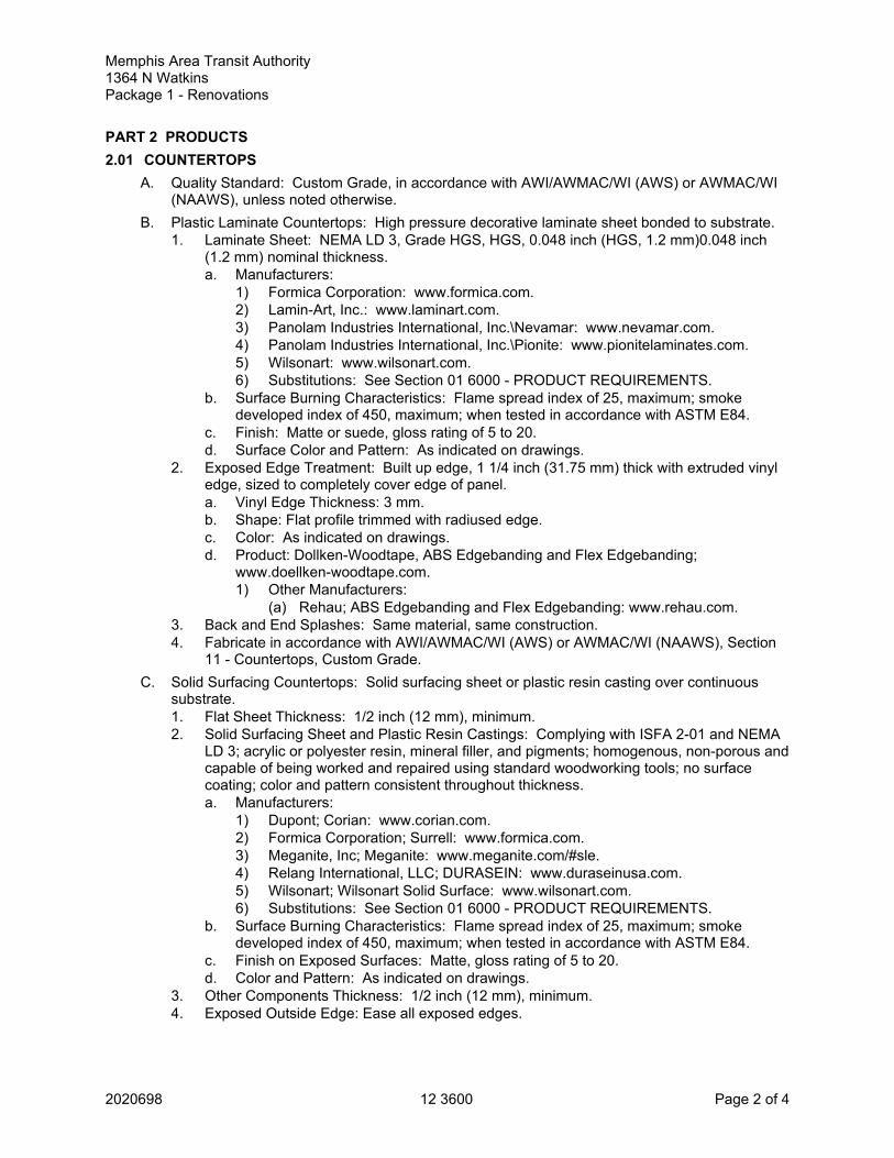
2020698 12 3600 Page 2 of 4
Memphis Area Transit Authority 1364 N WatkinsPackage 1 - Renovations
PART 2 PRODUCTS2.01 COUNTERTOPS
A. Quality Standard: Custom Grade, in accordance with AWI/AWMAC/WI (AWS) or AWMAC/WI(NAAWS), unless noted otherwise.
B. Plastic Laminate Countertops: High pressure decorative laminate sheet bonded to substrate.1. Laminate Sheet: NEMA LD 3, Grade HGS, HGS, 0.048 inch (HGS, 1.2 mm)0.048 inch
(1.2 mm) nominal thickness.a. Manufacturers:
1) Formica Corporation: www.formica.com.2) Lamin-Art, Inc.: www.laminart.com.3) Panolam Industries International, Inc.\Nevamar: www.nevamar.com.4) Panolam Industries International, Inc.\Pionite: www.pionitelaminates.com.5) Wilsonart: www.wilsonart.com.6) Substitutions: See Section 01 6000 - PRODUCT REQUIREMENTS.
b. Surface Burning Characteristics: Flame spread index of 25, maximum; smokedeveloped index of 450, maximum; when tested in accordance with ASTM E84.
c. Finish: Matte or suede, gloss rating of 5 to 20.d. Surface Color and Pattern: As indicated on drawings.
2. Exposed Edge Treatment: Built up edge, 1 1/4 inch (31.75 mm) thick with extruded vinyledge, sized to completely cover edge of panel.a. Vinyl Edge Thickness: 3 mm.b. Shape: Flat profile trimmed with radiused edge.c. Color: As indicated on drawings.d. Product: Dollken-Woodtape, ABS Edgebanding and Flex Edgebanding;
www.doellken-woodtape.com.1) Other Manufacturers:
(a) Rehau; ABS Edgebanding and Flex Edgebanding: www.rehau.com.3. Back and End Splashes: Same material, same construction.4. Fabricate in accordance with AWI/AWMAC/WI (AWS) or AWMAC/WI (NAAWS), Section
11 - Countertops, Custom Grade.C. Solid Surfacing Countertops: Solid surfacing sheet or plastic resin casting over continuous
substrate.1. Flat Sheet Thickness: 1/2 inch (12 mm), minimum.2. Solid Surfacing Sheet and Plastic Resin Castings: Complying with ISFA 2-01 and NEMA
LD 3; acrylic or polyester resin, mineral filler, and pigments; homogenous, non-porous andcapable of being worked and repaired using standard woodworking tools; no surfacecoating; color and pattern consistent throughout thickness.a. Manufacturers:
1) Dupont; Corian: www.corian.com.2) Formica Corporation; Surrell: www.formica.com.3) Meganite, Inc; Meganite: www.meganite.com/#sle.4) Relang International, LLC; DURASEIN: www.duraseinusa.com.5) Wilsonart; Wilsonart Solid Surface: www.wilsonart.com.6) Substitutions: See Section 01 6000 - PRODUCT REQUIREMENTS.
b. Surface Burning Characteristics: Flame spread index of 25, maximum; smokedeveloped index of 450, maximum; when tested in accordance with ASTM E84.
c. Finish on Exposed Surfaces: Matte, gloss rating of 5 to 20.d. Color and Pattern: As indicated on drawings.
3. Other Components Thickness: 1/2 inch (12 mm), minimum.4. Exposed Outside Edge: Ease all exposed edges.

Memphis Area Transit Authority 1364 N WatkinsPackage 1 - Renovations
2020698 12 3600 Page 3 of 4
5. Exposed Edge Treatment: Built up to minimum 1-1/4 inch (32 mm) thick unless shownotherwise; square edge with eased corner.
6. Back and End Splashes: Same sheet material, square top; minimum 4 inches (102 mm)high.
7. Skirts: As indicated on drawings.8. Fabricate in accordance with AWI/AWMAC/WI (AWS) or AWMAC/WI (NAAWS), Section
11 - Countertops, Premium Grade.2.02 MATERIALS
A. Wood-Based Components:1. Wood fabricated from old growth timber is not permitted.
B. Plywood for Supporting Substrate: PS 1 Exterior Grade, A-C veneer grade, minimum 5-ply;minimum 3/4 inch (19 mm) thick; join lengths using metal splines.
C. Particleboard for Supporting Substrate: ANSI A208.1 Grade 2-M-2, 45 pcf (20 kg/cu m)minimum density; minimum 1 inch (25.40 mm) thick; join lengths using metal splines.
D. Panel Goods for Supporting Countertops With Sinks:1. Plywood constructed with veneer core and hardwood veneers, fabricated with Type I
waterproof adhesive, suitable for receiving plastic laminate; or2. Particle board with phenolic resin, Type 2-M-2. Phenolic resin shall meet ANSI/AZ08.1
2-M-1, 2-M-2, 2-M-3 specifications.E. Adhesives: Chemical resistant waterproof adhesive as recommended by manufacturer of
materials being joined.F. Joint Sealant: Mildew-resistant silicone sealant, clear.
2.03 FABRICATIONA. Fabricate tops and splashes in the largest sections practicable, with top surface of joints flush.
1. Join lengths of tops using best method recommended by manufacturer.2. Fabricate to overhang fronts and ends of cabinets 3/4 inch (19 mm) except where top
butts against cabinet or wall.3. Prepare all cutouts accurately to size; replace tops having improperly dimensioned or
unnecessary cutouts or fixture holes.B. Provide back/end splash wherever counter edge abuts vertical surface unless otherwise
indicated.1. Secure to countertop with concealed fasteners and with contact surfaces set in waterproof
glue.2. Height: 4 inches (102 mm), unless otherwise indicated.
C. Plastic Laminate Countertops:1. Countertops: Construct with minimum 1 inch (25.4 mm) thick core. Provide plastic
laminate on top surface and backing sheet on underside of countertop.2. Back Splash: 3/4 inch (19 mm) core material with plastic laminate on top and exposed
surfaces; backing sheet on concealed surface.3. Sinks In Countertops: Apply clear silicone sealant at joint between backsplash and
countertop.4. Shop made joints in countertops are allowed only when required length exceeds
obtainable laminate length. Such joints shall touch throughout their length and be flushwithin a tolerance of .005 inch (0.127 mm). Joints between adjoining tops which must befield assembled shall be shop prepared with tight joint, bolt type connectors equal to TiteJoint Fasteners by Knape & Vogt.
D. Solid Surfacing Countertops: Fabricate tops up to 144 inches (3657 mm) long in one piece;join pieces with adhesive sealant in accordance with manufacturer's recommendations andinstructions.1. Provide continuous particleboard supporting substrate.
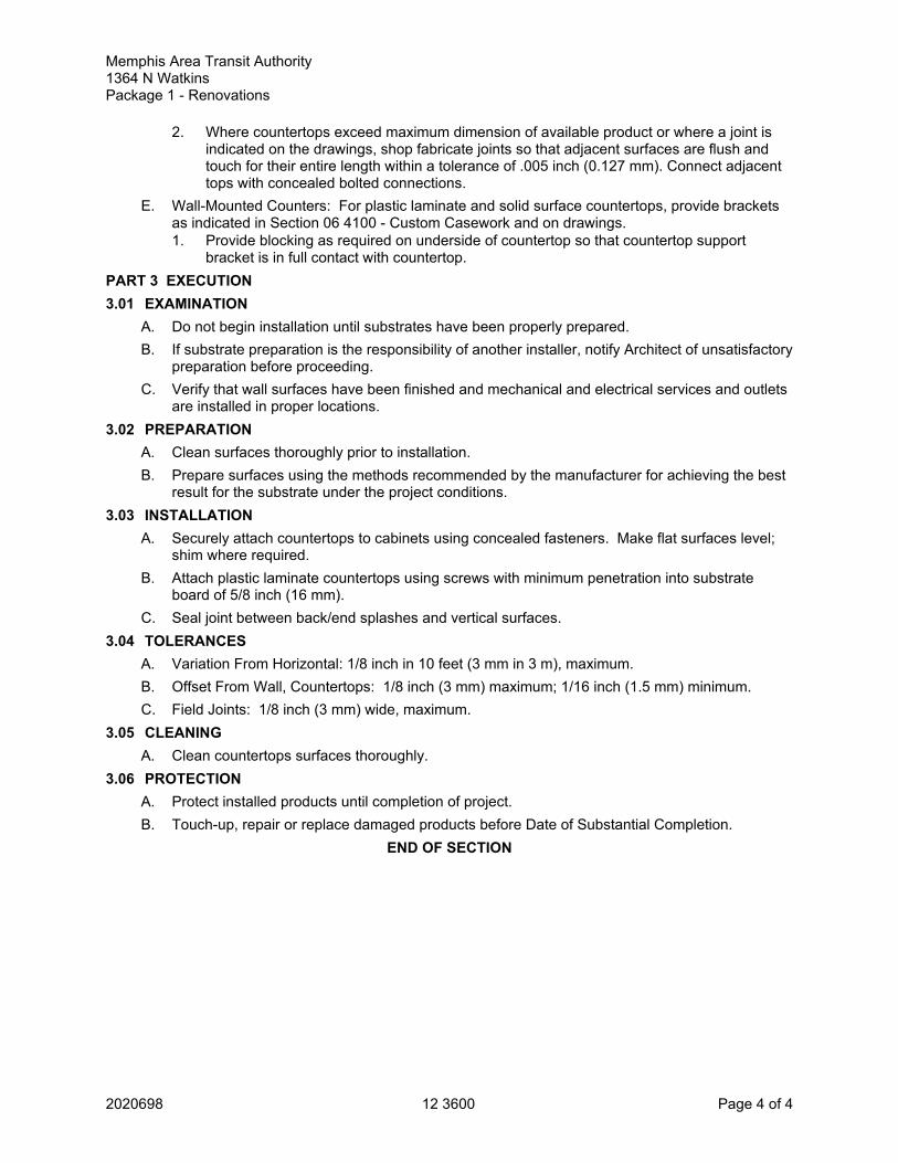
Memphis Area Transit Authority 1364 N WatkinsPackage 1 - Renovations
2020698 12 3600 Page 4 of 4
2. Where countertops exceed maximum dimension of available product or where a joint isindicated on the drawings, shop fabricate joints so that adjacent surfaces are flush andtouch for their entire length within a tolerance of .005 inch (0.127 mm). Connect adjacenttops with concealed bolted connections.
E. Wall-Mounted Counters: For plastic laminate and solid surface countertops, provide bracketsas indicated in Section 06 4100 - Custom Casework and on drawings.1. Provide blocking as required on underside of countertop so that countertop support
bracket is in full contact with countertop.PART 3 EXECUTION3.01 EXAMINATION
A. Do not begin installation until substrates have been properly prepared.B. If substrate preparation is the responsibility of another installer, notify Architect of unsatisfactory
preparation before proceeding.C. Verify that wall surfaces have been finished and mechanical and electrical services and outlets
are installed in proper locations.3.02 PREPARATION
A. Clean surfaces thoroughly prior to installation.B. Prepare surfaces using the methods recommended by the manufacturer for achieving the best
result for the substrate under the project conditions.3.03 INSTALLATION
A. Securely attach countertops to cabinets using concealed fasteners. Make flat surfaces level;shim where required.
B. Attach plastic laminate countertops using screws with minimum penetration into substrateboard of 5/8 inch (16 mm).
C. Seal joint between back/end splashes and vertical surfaces.3.04 TOLERANCES
A. Variation From Horizontal: 1/8 inch in 10 feet (3 mm in 3 m), maximum.B. Offset From Wall, Countertops: 1/8 inch (3 mm) maximum; 1/16 inch (1.5 mm) minimum.C. Field Joints: 1/8 inch (3 mm) wide, maximum.
3.05 CLEANINGA. Clean countertops surfaces thoroughly.
3.06 PROTECTIONA. Protect installed products until completion of project.B. Touch-up, repair or replace damaged products before Date of Substantial Completion.
END OF SECTION