Embed Size (px)
Citation preview

The 36th International Electric Propulsion Conference, University of Vienna
Vienna Austria, Sept. 15-20, 2019
Copyright © 2019 by Aerojet Rocketdyne. Published by the Electric Rocket Propulsion Society with permission
13kW Advanced Electric Propulsion Flight System
Development and Qualification
Presented at the 36th International Electric Propulsion Conference
University of Vienna • Vienna • Austria
September 15-20, 2019
Jerry Jackson1, Scott Miller2, Joseph Cassady3
Erich Soendker4, Ben Welander5, Matthew Barber6
Aerojet Rocketdyne, Los Angeles, CA and Redmond, WA, USA
Peter Peterson7
NASA Glenn Research Center, Cleveland, OH
The next phase of robotic and human deep space exploration missions requires high performance, high power
solar electric propulsion systems for large-scale science missions and cargo transportation. Aerojet Rocketdyne’s
Advanced Electric Propulsion System (AEPS) program will complete development and qualification of a 13kW flight
EP system to support NASA exploration. The first use of the AEPS is planned for the NASA Power & Propulsion
Element, which is the first element of NASA’s cis-lunar Gateway. The flight AEPS system includes a magnetically
shielded long-life Hall thruster, power processing unit (PPU), and xenon flow controller (XFC). The Hall thruster,
originally developed and demonstrated by NASA’s Glenn Research Center and the Jet Propulsion Laboratory,
operates at input powers up to 12.5kW while providing a specific impulse over 2600s at an input voltage of 600V.
The power processor is designed to accommodate an input voltage range of 95 to 140V, consistent with operation
beyond the orbit of Mars. The integrated system is continuously throttleable between 3 and 13.5kW. The program
has completed testing of the Technology Development Units and is progressing into the Engineering Development
Unit test phase and the final design phase to Critical Design Review (CDR). This paper will present the high power
AEPS system capabilities, overall program and design status and the latest test results for the 13kW flight system
development as well as the plans for the development and qualification effort of the EP string.
Nomenclature
AEPS = Advanced Electric Propulsion System
AR = Aerojet Rocketdyne
CDR = Critical Design Review
DMC = Discharge Master Controller
DSU = Discharge Supply Module
EDU = Engineering Development Unit
ETU = Engineering Test Unit
FPGA = Field Programmable Gate Array
1 Program Manager, Advanced In-Space Propulsion Program Office, [email protected] 2 Chief Engineer, AEPS Program Office, [email protected] 3 Sr. Director, Business Development, [email protected] 4 PPU Technical Lead, Avionics Engineering, [email protected] 5 HCT Technical Lead, Component Engineering, [email protected] 6 XFC Technical Lead, Component Engineering, [email protected] 7 SEP Project Lead Engineer, NASA GRC Electric Propulsion System Branch, [email protected].

Pg. 2
The 36th International Electric Propulsion Conference, University of Vienna
Vienna Austria, Sept. 15-20, 2019
GRC = Glenn Research Center
HERMeS = Hall Effect Rocket with Magnetic Shielding
JPL = Jet Propulsion Laboratory
PPE = Power and Propulsion Element
PPU = Power Processing Unit
SCB = System Control Board
SEP = Solar Electric Propulsion
STE = Special Test Equipment
STMD = Space Technology Mission Directorate
TDU = Technology Development Unit
TVAC = Thermal Vacuum
XFC = Xenon Flow Controller
XFCM = Xenon Flow Control Module
I. Introduction
The next phase of robotic and human deep space exploration missions will be enhanced by high performance,
high power solar electric propulsion systems for large-scale science missions and cargo transportation. Recent studies
for NASA’s Human Exploration and Operations Mission Directorate (HEOMD)
and Science Mission Directorate (SMD) have demonstrated that SEP capability,
with its substantially higher specific impulse (Isp), can be enabling for both near
term and future architectures and science missions.1 A high-power Solar Electric
Propulsion (SEP) element is integral to NASA’s Artemis lunar exploration
program, illustrated in Figure 2, which represents an approach to establish an
affordable evolutionary human exploration of Mars2. The Lunar Gateway is a key
element in this effort and will be used to demonstrate the capability of high power
solar electric propulsion. A part of this Lunar Gateway is the Power and
Propulsion Element (PPE) being developed by Maxar Technologies3, which will
employ SEP and demonstrate the AEPS thruster strings as part of its mission.
The development of a 13.5 kW Hall thruster system, led by the NASA Glenn Research Center (GRC) and the Jet
Propulsion Laboratory (JPL), began with the maturation of a high-power Hall thruster and power processing unit
internal to NASA. This technology development work has since transitioned to Aerojet Rocketdyne via a competitive
procurement selection for the Advanced Electric Propulsion System (AEPS) contract. The AEPS contract includes
the design, development, and qualification of a 13.5 kW Hall thruster electric propulsion system, which is baselined
on the PPE spacecraft and will be employed as a demonstration of the capabilities of high power Solar Electric
Propulsion.
Figure 1. Maxar PPE

Pg. 3
The 36th International Electric Propulsion Conference, University of Vienna
Vienna Austria, Sept. 15-20, 2019
Figure 2. NASA Artemis Program Phase One2
The AEPS System is an EP string that consists of a magnetically shielded Hall thruster, a Power Processing Unit
(PPU), a Xenon Flow Controller (XFC), and associated harnessing. The PPU receives up to 13.5 kW of power to
control the thruster output and operations. The 12.5kW Hall thruster uses xenon propellant and power from the PPU
to provide over 580 mN of thrust. The XFC is a low pressure flow system that is controlled by the PPU. An overview
of the electric propulsion (EP) string and how it interfaces with a notional spacecraft is shown in Figure 3. The AEPS
program has completed the System Requirement Review (SRR); the EP string, thruster, PPU and XFC Preliminary
Design Review (PDR); engineering model fabrication and is in the process of the development test campaign.
Figure 3. EP String Definition3
REU B
Solar Array
High-Voltage
Power
Distribution
PPU 1
XFC
1PMA
Spacecraft Avionics
28-V PowerCommand & ControlHigh-Voltage PowerPropellant Line
Xenon Tanks
1553
1553
Temperature
SensorsREU A
High-Voltage
Down
Converter
T G A 1
FT
1
EP String
28-V Power
Distribution Unit
Harness
Definition of EP String
Legend:
REU: Remote Engineering Unit
TGA: Thruster Gimbal Assembly
FT: Flight Thruster
XFC: Xenon Flow Controller
PPU: Power Processing Unit
PMA: Propellant Management Assembly
28V: Low Voltage Bus

Pg. 4
The 36th International Electric Propulsion Conference, University of Vienna
Vienna Austria, Sept. 15-20, 2019
The AEPS Hall thruster is based upon the 12.5 kW Hall Effect Rocket with Magnetic Shielding (HERMeS),
shown in Figure 4, that was originally developed and demonstrated by NASA GRC and JPL. The thruster operates at
input powers up to 12.5 kW while providing a specific
impulse of over 2600 s at a discharge voltage of 600 V. The
thruster design resulted in an estimated life of 50,000 hours4
enabled by magnetic shielding which was first demonstrated
by Aerojet Rocketdyne and JPL on the BPT-4000 (XR-5).5
NASA continues to perform further development testing of
the HERMeS Technology Development Units (TDUs)
including long duration wear testing which began in Oct.
2017 and collected information on erosion rates.
Additionally, NASA has performed environmental testing
and cathode development in order to better understand
implications for spacecraft accommodations and mitigate
risk for the AEPS program.6
The AEPS PPU leverages the work performed by NASA
GRC on a brassboard power processor that was utilized in the
integration testing of the HERMeS thruster.7 The brassboard
High Power 120/800 V Power Processing Unit (HP 120/800
V PPU) was required to have all of the functionality to operate
a Hall thruster, including the auxiliary power, master control
board, telemetry, and filters (see Figure 5). The unique aspect
of this development was the wide range (95 to 140 V) of the
input voltage for the PPU. The test results of the HP 120/800
V 15 kW PPU helped to guide the new design of the AEPS
PPU. Additionally, NASA has performed in depth testing of a prototype power module for the AEPS PPU.8
Unlike the HCT or PPU, the fidelity of the Xenon Flow Controller (XFC) for
AEPS is already at a high Technology Readiness Level (TRL). The AEPS XFC is
a derivative of the Xenon Flow Control Module (XFCM), see figure 5, which was
previously developed under a NASA contract by VACCO.9 The XFCM is a highly
integrated feed system that accepts unregulated xenon directly from storage tanks
and outputs precision, throttleable flow through two independent channels. The
XFCM completed qualification testing and was delivered to NASA GRC on 7 June
2012. Aerojet Rocketdyne is currently developing two EDU fidelity units to
complete the development testing of the AEPS EP string.
AEPS is a NASA contract from the Space Technology Mission Directorate (STMD) that was competitively-
selected10 and consists of the development of an Engineering Development Unit (EDU) EP string with an option for
qualification of a flight system. The Maxar Technologies PPE program will also procure two flight systems in order
to support their objectives in regards to the demonstration of Solar Electric Power. The AEPS program was awarded
to Aerojet Rocketdyne on April 28 of 2016. In execution of this program, there is close collaboration between Aerojet
Rocketdyne, NASA GRC, and JPL. The industry AEPS team includes two Aerojet Rocketdyne sites, Redmond and
Los Angeles, as well as ZIN Technologies, who is providing elements of the PPU, and VACCO, who is providing the
Figure 5. Brassboard PPU
Figure 4. HERMeS Thruster
Figure 6. VACCO XFCM
Pg. 5
The 36th International Electric Propulsion Conference, University of Vienna
Vienna Austria, Sept. 15-20, 2019
XFC. The management of the contract is being led by the NASA Glenn Research Center and testing is conducted at
NASA GRC and at JPL.
Originally presented at the 2017 IEPC conference11, this paper provides an update on the status of the AEPS
program, including updates to the thruster and PPU, as well as a summary on the planned development test campaign.
This paper will present the high power AEPS capabilities, overall program and design status and the latest test results
for the 13.5kW flight system development.
II. System Architecture
The primary design objective for the system architecture is to provide a high performance propulsion system that
efficiently utilizes both electrical power and propellant. The system provides the capability to throttle between 3kW
and 13.5kW of system input power providing a range in discharge voltage between 300V and 600V. The expected
performance for AEPS is summarized in Table 1 below. While the system will be qualified down to power levels of
3kW, this power level is outside of nominal operation and was not included in the table. The required system input
power and propellant flow rates will be determined by the throttle set points commanded by the spacecraft. Significant
effort has been focused on maximizing the electrical efficiency of each component of the propulsion string and
ensuring repeatable performance throughout the life of the mission.
A block diagram of the AEPS string is shown in Figure 7 including external interfaces to the spacecraft. The
system receives high voltage power for thruster operation and low voltage power for housekeeping and XFC operation
from the spacecraft power buses. The spacecraft command and data handling bus provides commands to the system
and receives telemetry from the system. The system receives pressure regulated xenon propellant from the spacecraft
xenon feed system.
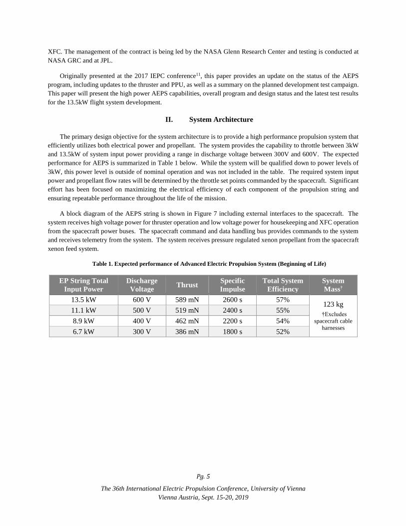
Table 1. Expected performance of Advanced Electric Propulsion System (Beginning of Life)
EP String Total
Input Power
Discharge
Voltage Thrust
Specific
Impulse
Total System
Efficiency
System
Mass†
13.5 kW 600 V 589 mN 2600 s 57% 123 kg
†Excludes
spacecraft cable
harnesses
11.1 kW 500 V 519 mN 2400 s 55%
8.9 kW 400 V 462 mN 2200 s 54%
6.7 kW 300 V 386 mN 1800 s 52%

Pg. 6
The 36th International Electric Propulsion Conference, University of Vienna
Vienna Austria, Sept. 15-20, 2019
INPUT
FILTER
ASSEMBLY
HOUSEKEEPING
POWER SUPPLY
BOARD
SYSTEM
CONTROL
BOARD)
XENON FLOW
CONTROL
BOARD
Thruster
XFC
J1
J4
J1
J3 J2
J2
J1
J9
HV Bus In
(95V-140V)
J7
LV Bus In
(28V)
J5
J6
J8
Vehicle
C&DH
(Mil-1553)
Test
RT Addr
PDP
(I-Sense)
Valve Control, Press. &
Temp. Sense
AEPS System Block Diagram
AUX POWER
SUPPLY
ASSEMBLY
DISCHARGE
SUPPLY UNIT
PPU
Mag Heaters &
Temp Sense
J3
Vehicle
Thermal
Mgmt
Xenon Vehicle
Propellant
Mgmt
Xenon
Pigtail
harnesses
are integral
to thruster
Cathode Heater, Keeper,
Inner & Outer Magnets
Discharge +, Discharge
Return, Body Current
Legend
Spacecraft Harnesses AEPS Harnesses Propellant Lines
Figure 7. Block diagram of AEPS string showing electrical and propellant interfaces
The AEPS harnessing between the components is designed to allow easier spacecraft integration and gimbaling
of the thruster by dividing the PPU-to-thruster power between two harnesses, thereby reducing the thickness and
stiffness as compared to using a single harness. One harness is dedicated to the primary discharge power. The other
is dedicated to thruster auxiliary power, which includes power required by the cathode heater, cathode keeper, and
electromagnets.
Propellant flow rate is controlled and regulated by the XFC via the PPU. Power from the PPU is provided to the
XFC on a single harness. The PPU provides the necessary current to open and close the XFC latch valve. The PPU
also provides the necessary voltages to control the size of the orifice in the piezoelectric anode and cathode valves,
which regulate the propellant flow rate to the anode and cathode propellant lines on the thruster.
The XFC and PPU are maintained within their required thermal environments via thermal conduction through
temperature-controlled mounting surfaces on the spacecraft. The AEPS architecture allows installation of the XFC
inside or outside of the spacecraft. The thruster is designed to be thermally uncoupled from the spacecraft. The thruster
is equipped with integrated heaters and temperature sensors that may be operated by the spacecraft thermal
management system to maintain the thruster above its minimum qualified temperature limits. This allows the thruster
to be located on a gimbal or boom far away from temperature-controlled surfaces and minimize plasma impingement
on spacecraft surfaces.
The system architecture includes test connectors to facilitate electrical functional tests of the XFC and thruster.
These functional tests may be performed during spacecraft integration and testing without requiring additional mating

Pg. 7
The 36th International Electric Propulsion Conference, University of Vienna
Vienna Austria, Sept. 15-20, 2019
and de-mating of the harnesses. The architecture also provides the spacecraft with accurate measurements of anode
and cathode propellant flow rates and all relevant voltages and currents, as shown in the two columns of telemetry in
Table 2. The EP string has 8 modes of operation which are defined in Table 3 and Figure 8.
Table 2. Analog Telemetry
Analog Telemetry
Cathode heater DC current High voltage bus input DC voltage
Cathode heater DC voltage High voltage bus input DC current
Cathode keeper DC current Low voltage bus input DC voltage
Cathode keeper DC voltage Low voltage but input DC current
Inner Magnet DC Current Discharge current ripple
Inner Magnet DC Voltage Discharge voltage ripple
Outer Magnet DC Current PPU Housekeeping DC Voltage
Outer Magnet DC Voltage XFC Anode-Leg flow control device Temperature
Discharge DC Current XFC Anode-Leg Pressure
Discharge DC Voltage XFC Cathode-Leg flow control device Temperature
Cathode-to-PPU-chassis DC voltage XFC Cathode-Leg Pressure
Cathode-to-thruster-body DC current XFC drive currents and voltages
PPU Temperatures
Table 3. AEPS Modes of Operation
Mode Description
Unpowered All PPU outputs off and XFC valves closed. No communication.
Boot Only mode that can accept software updates.
Standby Bus inputs are in range, communications available, all outputs off.
Initialization Events such as system bakeout, cathode conditioning, etc.
Operation Startup, steady-state thrusting, throttling, shutdown.
Manual Allows user to independently control each output of the PPU.
Maintenance Code maintenance activities such as parameter updates, data table updates, and
memory verification.
Safe Places string in a safe state. All outputs off, communications available.
Figure 8. AEPS Modes of Operation

Pg. 8
The 36th International Electric Propulsion Conference, University of Vienna
Vienna Austria, Sept. 15-20, 2019
For nominal thrusting operations, when power is applied, the system performs initialization checks and waits for
spacecraft commands to perform requested operations. The system initiates startup following receipt of the spacecraft
command. The initialization sequences are performed only once during the initial operation on-orbit. They include
venting of the propellant feed system, bakeout of the thruster, and cathode conditioning. The operation mode consists
of four states shown in Figure 9. The system can transition between any two operational states when commanded by
the spacecraft. The “Heater Only” and “Keeper Only” states maintain requisite cathode temperatures for efficient
electron emission and keep the EP string in a state of readiness for rapid thruster start. While in the “Thruster Control”
state, the system can maintain a constant throttle level, perform a thruster start, throttle to a new operating point, or
shut down.
In the event of anomalous operation, AEPS will self-protect through an integral fault monitoring system. If
telemetry strays outside of the expected range, the PPU will notify the spacecraft of the anomaly. The spacecraft has
the option to maintain the current operating point or change operating points in an effort to resolve the anomaly. If
telemetry strays too far from its expected range, the PPU will notify the spacecraft of a fault and then perform an
automated shutdown of the system to avoid potential damage. The design of the fault protection system allows for
reconfiguration throughout the mission.
The major control loop within AEPS is focused on achieving the desired thruster discharge current commanded
by the spacecraft. The PPU does not control discharge current directly. Instead, it regulates propellant flow rate to
the thruster. While the electrical interactions between the PPU and thruster are very fast, the propellant flow
interactions between the XFC and thruster are very slow. Transients associated with these interactions may occur
over several seconds or less than a millisecond. Designing a control loop that provides the prompt command response
desired by the mission and stability against a wide spectrum of perturbations is challenging, especially when the
system is designed to allow integration on a variety of spacecraft configurations.
Figure 9. AEPS Operation Sequences

Pg. 9
The 36th International Electric Propulsion Conference, University of Vienna
Vienna Austria, Sept. 15-20, 2019
To ensure successful development of the AEPS flight system, Aerojet Rocketdyne is developing a time dependent
system performance model to address the interactions between components, design adjustments, production tolerances
as well as the major interactions with the spacecraft.12 The AEPS system performance model has been designed to
account for all these interactions in a way that allows evaluation of the sensitivity of the system to expected changes
over the planned mission as well as to assess the impacts of normal component and assembly variability during the
production phase of the program. The results will be used to address the component requirements to mitigate driving
system cost or overly constraining the development program. Finally, the model will be available to quickly
troubleshoot any future unforeseen development challenges.
System level hot-fire testing will be performed on development hardware in early 2020. Qualification testing will
be performed on two strings of production units starting in mid-2021. As part of the current program, AR has
developed and is validating an automated test system specifically for integrated string testing of AEPS.
III. Thruster
The AEPS thruster design derives from the NASA HERMeS Technology Development Unit (TDU). The
HERMeS TDU is a magnetically shielded, 12.5 kW thruster with a center-mounted cathode and graphite pole covers
and has been described in previous papers13,16. The cathode is electrically tied to the conductive pole covers of the
TDU. The HERMeS TDU has demonstrated operation at discharge currents in excess of 30A and discharge voltages
up to 800 V.14 With this novel electrical configuration and effective magnetic shielding, the TDU has demonstrated
the low erosion rates necessary to meet the mission requirement of 23,000 hours of operation.15 By maintaining key
gas distributer and magnetic circuit design features of the HERMeS design, the performance capability of the AEPS
thruster is expected to be in family with the NASA HERMeS TDUs, which achieved total efficiencies up to 68% and
specific impulses up to 2900 s.17
Aerojet Rocketdyne has performed a series of design modifications to the HERMeS thruster to improve its ability
to meet environmental and spacecraft interface requirements, as previously described in the 2017 IEPC paper.11 Some
requirements have been modified, as the primary mission for the AEPS demonstration evolved from the ARRM to the
PPE mission. The most notable changes are a 50% reduction of shock requirement at 100 Hz, relaxation of the thrust
vector alignment requirement and the cathode design has been modified to improve manufacturability (see Figure 10).
Additionally, changes were made to facilitate spacecraft pointing.
Figure 10. CAD image of AEPS Hall Current Thruster showing integrated harness assemblies

Pg. 10
The 36th International Electric Propulsion Conference, University of Vienna
Vienna Austria, Sept. 15-20, 2019
Tooling and special test equipment to support thruster assembly and shipment, as well as component and system
level testing has been developed and fabricated. This support equipment will be verified during manufacturing and
test of two Engineering Test Unit (ETU) thrusters. The first development unit, ETU-1, has been assembled and is in
hot fire testing at JPL. Figure 11 shows this thruster in the assembly area at our Redmond, WA facility prior to being
shipped to JPL.
Figure 11 – AEPS ETU-1 Thruster in Assembly and in Hot Fire Testing at JPL
The second development unit, ETU-2, is currently in final assembly at Redmond. Testing of the two thrusters is
planned to take place in Redmond, at NASA GRC, at JPL, and at the Aerospace Corporation. One ETU thruster will
undergo hot fire performance, dynamic and thermal qualification level environmental testing, and radiated emissions
testing; and the other will undergo hot fire performance, plasma characterization, and wear testing. Qualification
testing of the first production units is planned to begin in mid-2021.
IV. Power Processing Unit
The AEPS PPU provides discharge power to the thruster as well as system control and other associated functions.
The PPU provides up to 20.8 A of discharge current over a variable voltage output range of 300 to 600 V. Other
features include XFC control, heater power, keeper power, inner magnet power, outer magnet power, telemetry,
system health monitoring, and spacecraft communications.
As was presented at the 2017 IEPC conference, the Discharge Supply Unit (DSU) was divided into six power
modules.11. After early testing, the architecture was optimized which resulted in a DSU with four power modules. The
present PPU design provides for over 95% efficiency for the DSU with an input voltage at 95V to 140V.8
The PPU can provide over 13 kW of regulated power to the thruster. The PPU has a wide output operating range,
which is illustrated in Figure 12. The green area is the system specified operation range and the blue areas are the
capability. Additionally, the PPU controls the thruster output and operations. The PPU commands the XFC to provide
the flow required to achieve the spacecraft commanded thrust within 1.25%. The PPU also contains advanced health
monitoring and fault protection based on the telemetry listed in Table-2 above. The output ripple telemetry offers a
unique set of HCT health monitoring by reporting voltage end current peak-peak and RMS values, which can be used
to diagnose thruster behavior.

Pg. 11
The 36th International Electric Propulsion Conference, University of Vienna
Vienna Austria, Sept. 15-20, 2019
Figure 12. Discharge Supply Unit Output Voltage & Current Range
The Discharge Supply Unit (DSU) has four individually controllable Power Modules (PM), which can provide a
degraded mode of operation in the event of an individual PM failure. Additionally, each PM has a Primary Over-
Current (POC) protection circuit mitigating the effects of radiation-induced events. The programmable current and
fault protection limits of the DSU allow the mission planners to adjust as needed. The heater power supply is sized to
provide enough power to activate a LaB6 cathode. These design features provide significantly more EP system health
monitoring as well as the control parameters to effect the system heal and performance for a long life mission.
V. Xenon Flow Controller
VACCO has been providing electric propulsion components and feed systems for over 20 years. In order to
minimize the size and mass of future xenon feed systems, VACCO developed and qualified a Xenon Flow Control
Module (XFCM) based on their Chemically Etched Micro Systems (ChEMS™) technology. This XFCM became the
basis for the AEPS XFC.
VACCO teamed with Aerojet Rocketdyne on AEPS with responsibility for the Xenon Flow Controller (XFC), an
application-engineered version of VACCO’s qualified XFCM. The result is a highly-integrated, compact, low-mass
subsystem that provides:
10 Micron propellant filtration
A Micro Latch Valve for propellant isolation
Independently throttleable flow to both the Anode and Cathode
Flow rate feedback
With minor design adjustments the XFC is capable of supporting a wide range of flow regimes and electric
thrusters well beyond 12.5 kW. The AEPS XFC weighs less than 1.8 kg and measures less than 8 x 8 x 20 cm, with
one inlet tube and two outlet tubes. It consists of two major sub-assemblies; a manifold and an enclosure.

Pg. 12
The 36th International Electric Propulsion Conference, University of Vienna
Vienna Austria, Sept. 15-20, 2019
Figure 13. AEPS XFC
The manifold is all-welded against external leakage with inlet and outlet tubes welded to the outside and the
functional components mounted on the inside. Interconnecting flow paths between components are machined into the
manifold eliminating the need for tubing. The enclosure provides environmental protection for the electrical
components and four mounting holes for structural attachment. An electrical connector provides the electrical
interface to the PPU.
P/T
P/T
Anode
Cathode
Flow Restrictors
40 Micron Outlet Filters
Low Pressure & Temperature (RTD)
TransducerPFCV
Latch Valve
10 Micron Inlet Filter
Xenon Input at 40 psia
High Pressure Proportional Flow
Control Valves
PFCV
XFC Diagram P/N: A07311200-001
Figure 14. XFC Diagram
Propellant enters the XFC through an inlet tube equipped with an integral 10 micron etched disc filter. Flow then
passes through a micro latch valve that, when latched closed, provides the first interrupt against internal leakage.
When latched open, flow from the micro latch valve splits into anode and cathode branches. Both branches are
identical except for their flow restrictors. Each branch contains a proportional flow control valve (PFCV), a 50kRad
tolerant pressure and temperature transducer, and an integrated 40 micron outlet filter/flow restrictor. Flow is
controlled by modulating the PFCV to regulate pressure upstream of the flow restrictor. When unpowered, the
normally-closed PFCV closes and seals, providing a second interrupt against internal leakage for each flow branch.

Pg. 13
The 36th International Electric Propulsion Conference, University of Vienna
Vienna Austria, Sept. 15-20, 2019
Inlet pressure is regulated by the spacecraft to a nominal 40 psia, and the XFC can control Xenon flow with inlet
pressures up to 100 psia.
The XFC provides a flow rate of 8 to 24 mg/second of xenon with the ability to set the cathode to anode flow
split through independent control of the anode and cathode proportional flow control valves. Cathode flow will be
between 5 and 10 percent of the anode flow. The XFC design has less than 1.0 X 10⁻⁴ sccs of internal helium leakage
and less than 1 X 10⁻⁶ sccs of external leakage.
Each XFC will be calibrated to provide a flow rate uncertainty of ±1.5% at the inlet pressure of 40 psia and over
a temperature range of 20°C to 45°C. Development testing of an XFCM in April 2018 using a primary flow meter
provided confidence that the XFC nominal flow rate uncertainty will be better than ±1.5% with in-space zeroing of
the pressure transducers to eliminate zero drift error due to thermal and radiation exposure over life. The XFC design
has already been qualified to vibration and shock levels in excess of the AEPS vibration levels of 8.1 grms for
acceptance testing, 11.4 grms for qualification and shock levels of up to 2000 g's.
The XFC is specifically designed for the long durations required by future exploration missions. To that end, the
internal components are designed for infinite fatigue life. Component fatigue life has been verified by analysis, except
for the proportional actuators, which will be verified by third-party testing. The XFC is capable of a throughput
greater than 1770 kg of xenon. Two EDUs will be fabricated and one will go through qualification-like testing in
2019. Full qualification testing will be performed on the first flight production unit in 2021.
VI. Development and Qualification Status
Aerojet Rocketdyne’s approach to hardware development testing for the AEPS program is based on the model
that was successfully executed recently on several AR NASA programs. In addition to design capability assessment,
the use of flight-like “pathfinder” hardware is intended to identify manufacturing, assembly, and test issues in build
paperwork, documentation, inspection/verification methods, tooling, Special Test Equipment (STE), and
part/assembly interferences prior to the final design phase. This allows the program to incorporate corrections and
lessons learned in these areas and to resolve any critical design related issues during the final design phase prior to
qualification. This approach has been shown to significantly reduce schedule risk during qualification, when all
documentation has been released and any issue or nonconformance must be worked under formal quality control
procedures. When qualification and production are planned to occur in parallel as on the AEPS program, this approach
becomes of critical importance as any production issue or redesign activity could directly impact the flight article
delivery dates.
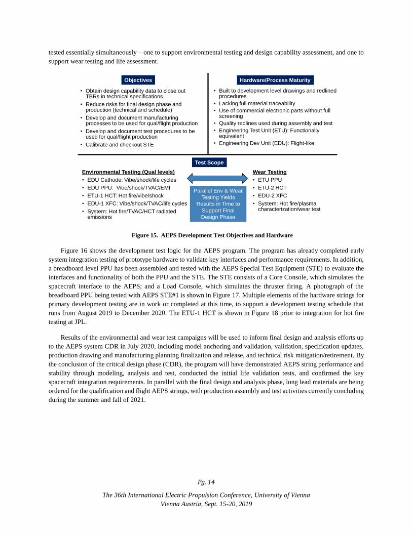
Figure 15 shows a summary of the objectives and scope of the AEPS development test plan. The EDU hardware
used for development testing is identical in form, fit, and function to the final flight design, but is designed, built and
tested under engineering controls with potentially less-than-flight level components and material traceability, built to
development level drawings and work instructions, and controlled under development level quality assurance
procedures. This allows for more rapid and streamlined manufacturing, assembly, and testing efforts. An ETU PPU
is also being built in parallel with the EDU PPU. The ETU PPU is functionally equivalent to the EDU PPU but is not
packaged in a flight-like enclosure. This unit will be used for bench testing to verify electrical functional requirements
such that any issues can be uncovered as soon as possible in the development cycle. It will also be used to power the
development EP string used for wear test/life evaluation, as functionality is the driving PPU requirement for this
particular test sequence. Development testing will be conducted at the component level (EDU cathode), subsystem
level (PPU, HCT, XFC), and system (AEPS string) level. In order to obtain data to support final design and analysis
and the program schedule for qualification and production, two sets of development hardware are being built to be
Pg. 14
The 36th International Electric Propulsion Conference, University of Vienna
Vienna Austria, Sept. 15-20, 2019
tested essentially simultaneously – one to support environmental testing and design capability assessment, and one to
support wear testing and life assessment.
Figure 15. AEPS Development Test Objectives and Hardware
Figure 16 shows the development test logic for the AEPS program. The program has already completed early
system integration testing of prototype hardware to validate key interfaces and performance requirements. In addition,
a breadboard level PPU has been assembled and tested with the AEPS Special Test Equipment (STE) to evaluate the
interfaces and functionality of both the PPU and the STE. The STE consists of a Core Console, which simulates the
spacecraft interface to the AEPS; and a Load Console, which simulates the thruster firing. A photograph of the
breadboard PPU being tested with AEPS STE#1 is shown in Figure 17. Multiple elements of the hardware strings for
primary development testing are in work or completed at this time, to support a development testing schedule that
runs from August 2019 to December 2020. The ETU-1 HCT is shown in Figure 18 prior to integration for hot fire
testing at JPL.
Results of the environmental and wear test campaigns will be used to inform final design and analysis efforts up
to the AEPS system CDR in July 2020, including model anchoring and validation, validation, specification updates,
production drawing and manufacturing planning finalization and release, and technical risk mitigation/retirement. By
the conclusion of the critical design phase (CDR), the program will have demonstrated AEPS string performance and
stability through modeling, analysis and test, conducted the initial life validation tests, and confirmed the key
spacecraft integration requirements. In parallel with the final design and analysis phase, long lead materials are being
ordered for the qualification and flight AEPS strings, with production assembly and test activities currently concluding
during the summer and fall of 2021.
• Obtain design capability data to close out TBRs in technical specifications
• Reduce risks for final design phase and production (technical and schedule)
• Develop and document manufacturing processes to be used for qual/flight production
• Develop and document test procedures to be used for qual/flight production
• Calibrate and checkout STE
• Built to development level drawings and redlined procedures
• Lacking full material traceability
• Use of commercial electronic parts without full screening
• Quality redlines used during assembly and test
• Engineering Test Unit (ETU): Functionally equivalent
• Engineering Dev Unit (EDU): Flight-like
Hardware/Process MaturityObjectives
Test Scope
Environmental Testing (Qual levels)
• EDU Cathode: Vibe/shock/life cycles
• EDU PPU: Vibe/shock/TVAC/EMI
• ETU-1 HCT: Hot fire/vibe/shock
• EDU-1 XFC: Vibe/shock/TVAC/life cycles
• System: Hot fire/TVAC/HCT radiated emissions
Wear Testing
• ETU PPU
• ETU-2 HCT
• EDU-2 XFC
• System: Hot fire/plasma characterization/wear test
Parallel Env & Wear
Testing Yields
Results in Time to
Support Final
Design Phase

Pg. 15
The 36th International Electric Propulsion Conference, University of Vienna
Vienna Austria, Sept. 15-20, 2019
Figure 16. AEPS Development Test Logic
Figure 17. Breadboard PPU in Test (STE in Background)
ETU-1 HCT Build
(with Workhorse
Cathode) and ATP
EDU-1 XFC Build
and ATP
EDU PPU Build and
ATP
Qual-Level Vibe &
Shock Testing
Qual-Level Vibe, Shock
& TVAC Testing
EDU-1 Cathode Build
and ATP
Install EDU-1
Cathode into ETU-1
HCT
TVAC Testing
ETU PPU Build
and ATP
HCT ETU-2 Build
(w/ Workhorse
Cathode) and ATP
EDU-2 XFC Build
and ATP
Ref.
Hot-Fire
500 Hour
Wear Test
Ref.
Hot-Fire
Extended
Wear Test
Ref.
Hot-Fire
Environmental and Hot-Fire Testing
Hot-Fire and Wear Testing
Qual-Level Vibe &
Shock Testing
LIFRef.
Hot-Fire
EDU PPU EMI &
Power Quality Testing
Ref.
Hot-Fire
Ref.
Hot-Fire
Radiated
Emissions
Ref. Hot-Fire
Shock, Vibe, TVAC,
Life Cycles
PPU testing
HCT Testing
XFC Testing
Integrated
String Testing
EDU-2 Cathode Build
and ATPLife Cycle Testing
Complete
In Work
In Work
In Work
In Work
In Work
In Work
In Work
In Work

Pg. 16
The 36th International Electric Propulsion Conference, University of Vienna
Vienna Austria, Sept. 15-20, 2019
Figure 18. AEPS ETU-1 Hall Current Thruster prior to Integration for Hot Fire Test
The AEPS approach to qualification testing includes two production qualification strings. Two qualification
strings rather than one are used in order to compress the overall duration of the qualification program to support
completion prior to launch of the first flight hardware shipset. Similar to the development testing approach, one
qualification string is used for environmental test verification, and one qualification string is used for life (wear) test
verification. Upon completion of the qualification test campaign, the test data together with design and analysis results
from the final design phase are used to complete formal verification of all AEPS system requirements. Life verification
of the AEPS string is planned to be accomplished via a combination of a 4500 hour system qualification life test,
component level life tests, Failure Modes and Effects Analysis results, and analytical extrapolations. Qualification
verification activities are currently planned to be completed in mid-2022. Figure 19 shows a summary of the objectives
and scope of the qualification test plan, and Figure 20 shows the qualification test plan logic.
Figure 19. AEPS Qualification Test Objectives
• Complete formal verification of component and system environmental and life requirements
• PPU• HCT• XFC• System
• Determine if the system has any operational restrictions over life
Hardware/Process MaturityObjectives
Test Scope
Environmental Testing: Qual String #1
• Flight production PPU, HCT, XFC subsystem acceptance tests
• Subsystem level qual vibe, shock
• Subsystem level TVAC/EMI/EMC
• System level hot fire test
• Thruster radiated emissions
Wear Testing: Qual String #2
• Flight production PPU, HCT, XFC component acceptance test
• System level hot fire test
• System level wear test
Parallel Env &
Wear Testing
Yields Results
Prior to First
Launch
• Flight production hardware built to formally
released and configuration controlled drawings
and work instructions
• Full material traceability
• Qualified processes
• Formal quality control during assembly and test

Pg. 17
The 36th International Electric Propulsion Conference, University of Vienna
Vienna Austria, Sept. 15-20, 2019
Figure 20. AEPS Qualification Test Logic
VII. Conclusion
The AEPS program has completed the design phase and has transitioned to the development test phase. The
component teams have incorporated design improvements to their respective designs based on early breadboard testing
and preliminary analysis. Engineering Development Unit hardware testing is underway with extensive component
testing and system level operation planned for the remainder of 2019 and early 2020. NASA continuies to investigate
the performance of the HERMeS thruster in order to inform the final flight design of the AEPS thruster.10 Based on
the test campaign and the NASA HERMeS test data, the program will finalize the flight design and a CDR will then
be held to document the final design and analysis. Fabrication of the qualification units will occur upon completion
of the CDR. The program is on track to complete the component and system qualification testing in 2022 as well as
delivery of two flight EP strings.
VIII. Ackowledgments
The AEPS program team would like to thank the NASA Space Technology Mission Directorate for their
continued support of the work discussed in this paper and all the AEPS reviewers, technical consultants and team
members at Aerojet Rocketdyne and NASA who have contributed to the success of the program to date. Portions of
the research described in this paper were carried out at the Jet Propulsion Laboratory, California Institute of
Technology, under a contract with the National Aeronautics and Space Administration.
Qual String #2 – Hot Fire and Wear Testing
Qual String #1 – Environmental
Individual String
Elements (PPU, HCT
and XFC) Subjected
to Acceptance
Testing Only
Conduct 4500
hour Wear
Test
Qual String #2
Turned Over to
NASA for
Additional Wear
Testing
PPU Acceptance
Testing (Functional,
Vibration, Thermal
Vacuum)
PPU Qual
Vibration &
Shock Testing
HCT Acceptance
Testing (Functional,
Vibration)
XFC Acceptance
Testing (Functional,
Vibration)
HCT Qual
Vibration and
Shock Testing
XFC Qual
Vibration &
Shock Testing
Conduct TVAC
at JPL
(ETU/EDU
PPU & EDU
XFC)
Qualification
Testing
Complete
Ref.
Hot-Fire
at GRC
EP String Level
Subsystem Level
Conduct
Radiated
Emissions
Test at
Aerospace
Corp.
PPU TVAC,
EMI/EMC and
Power Quality
Testing
XFC TVAC
Ref.
Hot-Fire
at GRC
Ref.
Hot-Fire
at GRC
Ref.
Hot-Fire
at GRC
Conduct
LIF
Ref.
Hot-Fire
at GRC
Ref.
Hot-Fire
at GRC

Pg. 18
The 36th International Electric Propulsion Conference, University of Vienna
Vienna Austria, Sept. 15-20, 2019
IX. References
1 Cassady, J. et. al, "Next Steps In The Evolvable Path To Mars," IAC-15-D2,8-A5.4,8, 66th International
Astronautical Congress, Jerusalem, Israel, 12–16 October 2015
2 Free, J., "Architecture Status," NASA Advisory Council Human Exploration and Operations Committee Meeting,
https://www.nasa.gov/sites/default/files/atoms/files/march_2017_nac_charts_architecturejmf_rev_3.pdf, [cited
March 28, 2017].
3 investor.maxar.com/investor-news/press-release-details/2019/Maxar-Selected-to-Build-Fly-First-Element-of-
NASAs-Lunar-Gateway/default.aspx
4 Hofer, R. R., et al., “The 12.5 kW HERMeS Hall thruster for the Asteroid Redirect Robotic Mission,” AIAA-
2016-4825, 52nd AIAA/SAE/ASEE Joint Propulsion Conference, Salt Lake City, UT, July 25-27, 2016.
5 Mikelledes, I. Katz, I, Hofer, R., Goebel, D., de Grys, K. Mathers, A., “Magnetic Shielding of the Channel Walls
in a Hall Plasma Accelerator,” Physics of Plasmas 18, 33501 (2011).
6 D. M. Ahern, J. D. Frieman, G. Williams, J. Mackey, T. Haag, W. Huang, and H. Kamhawi, "In-situ Diagnostic
for Assessing Hall Thruster Wear," presented at the 2018 Joint Propulsion Conference, AIAA-2018-4721,
Cincinnati, OH, 2018.
7 Santiago, W., et al, “High Input Voltage, Power Processing Unit Performance Demonstration,” AIAA-2016-5033,
52nd AIAA/SAE/ASEE Joint Propulsion Conference, Salt Lake City, UT, July 25-27, 2016
8 Soendker, E., et al, “13kW Advanced Electric Propulsion System Power Processing Unit Development,” IEPC-
2019-930, 36th International Electric Propulsion Conference, Vienna, Austria, Sept 15-20, 2019
9 Cardin, J. M., Cook, W., and Bhandari, R., “Qualification of an Advanced Xenon Flow Control Module,” IEPC-
2013-382, 33rd International Electric Propulsion Conference, Washington, DC, Oct. 6 - 10, 2013.
10 Peterson, P., et al, “Overview of NASA’s Solar Electric Propulsion Project,” IEPC-2019-836, 36th International Electric
Propulsion Conference, Vienna, Austria, Sept 15-20, 2019
11 Jackson, J., et al, “13kW Advanced Electric Propulsion Flight System Development and Qualification,” IEPC-
2017-223, 35th International Electric Propulsion Conference, Atlanta, GA, Oct 8-12, 2017
12 Stanley, S., Chew, G., Rapetti, R., Tofil, T., Herman, D., Allen, M., Jackson, J., and Myers, R. "Development of a
13 kW Hall Thruster Propulsion System Performance Model for AEPS", 53rd AIAA/SAE/ASEE Joint Propulsion
Conference, 2017.
13 D. A. Herman, W. Santiago, H. Kamhawi, J. E. Polk, J. S. Snyder, R. R. Hofer, and M. Parker, "The Ion
Propulsion System for the Asteroid Redirect Robotic Mission," in 52nd AIAA/SAE/ASEE Joint Propulsion
Conference, Salt Lake City, UT, 2016.
14 Kamhawi, H., Huang, W., Haag, T., Shastry, R., Thomas, R., Yim, J., Herman, D., Williams, G., Myers, J., Hofer,
R., Mikellides, I., Sekerak, M., and Polk, J., "Performance and Facility Background Pressure Characterization
Tests of NASA's 12.5-kW Hall Effect Rocket with Magnetic Shielding Thruster," Presented at the 34th
International Electric Propulsion Conference, IEPC-2015-007, Kobe, Japan, July 4-10, 2015.
15 Williams, G. J., Gilland, J. H., Peterson, P. Y., Kamhawi, H., Huang, W., Ahern, D. W., Yim, J., Herman, D. A.,
Hofer, R. R., and Sekerak, M., "Wear Testing of the HERMeS Thruster," AIAA-2016-5025, July 2016.

Pg. 19
The 36th International Electric Propulsion Conference, University of Vienna
Vienna Austria, Sept. 15-20, 2019
16 Hofer, R. R., Kamhawi, H., Mikellides, I., Herman, D., Polk, J., Huang, W., Yim, J., Myers, J., and Shastry, R.,
"Design Methodology and Scaling of the 12.5 kW HERMeS Hall Thruster for the Solar Electric Propulsion
Technology Demonstration Mission," Presented at the 62nd JANNAF Propulsion Meeting, JANNAF-2015-3946,
Nashville, TN, June 1-5, 2015.
17 Kamhawi, H., Huang, W., Haag, T., Yim, J., Herman, D., Peterson, P. Y., Williams, G., Gilland, J., Hofer, R., and
Mikellides, I., "Performance, Facility Pressure Effects, and Stability Characterization Tests of NASA's Hall Effect
Rocket with Magnetic Shielding Thruster," AIAA-2016-4826, July 2016.


![Fiber Optic (Flight Quality) Sensors For Advanced Aircraft Propulsion · · 2013-08-30(FLIGHT QUALITY) SENSORS FOR ADVANCED AIRCRAFT PROPULSION Fina] Report, Jan. 1990 ... 11.1](https://img.pdfslide.net/doc/110x75/5aec1fba7f8b9ab24d8f9cde/fiber-optic-flight-quality-sensors-for-advanced-aircraft-propulsion-flight-quality.jpg)