Embed Size (px)
Citation preview

GEN CO
DYNASET PRIORITY VALVE
PV SAE 3fl” -1 1/4~~
GENSCO EQUIPMENT (1990) Inc. GENSCO AMERICA INC.53 Carlaw Avenue 5307 Dividend DriveToronto, Canada Decatur, Georgia 30035M4M 2R6 Phone: 770-808-8711Phone: 416-465-7521 Fax: 770-808-8739Fax: 416-465-4489
Across USA Call 1-800-268-6797E Mail: info~penscoeguio cornInternet: www.genscoepuip.com
Serving indust,y world wide since 1919

WARRANTYALL ORDERS FOR PRODUCT ARE SUBJECT TO THE FOLLOWING:
Gensco Equipment (1990) Inc. warrants each product to be free from defects inmaterial and workmanship under normal use and service. Gensco Equipment’sobligation under this warranty is limited to repairing or supplying, at our option, apart or parts to replace any defective part or parts which fail, within one (1) yearfrom date of original sale. No product shall be returned without prior authorizedapproval, and if authorized, the transportation charges shall be prepaid to GenscoEquipment, Toronto, Canada, or Gensco America, Decatur, GA. Unauthorizedreturns will not be accepted.
The provisions of this warranty shall not apply to any part or parts which have beensubject to misuse, negligence or accident, or which have been repaired or alteredoutside of Gensco Equipment’s service department in any way, so, as in thejudgment of Gensco Equipment to affect adversely its performance, stability orreliability.
Gensco Equipment neither assumes nor authorizes anyone to assume for it anyother obligation or liability for any loss or damage, either direct, incidental orconsequential, resulting from or arising out of, or in connection with, any of itsdefective part or parts.
THIS WARRANTY IS EXPRESSLY IN LIEU OF ANY AND ALL OTHER WARRANTIES, EXPRESSEDOR IMPLIED, INCLUDING ANY IMPLIED WARRANTY OF MERCHANT ABILITY OR FITNESSFOR A PARTICULAR PURPOSE, AND OF ANY OTHER OBLIGATION OR LIABILITY ON THE
PART OF GENSCO EQUIPMENT OF ANY NATURE WHATSOEVER.
RETURN POLICY
A Returned Goods Authorization must be obtained from Gensco Equipment priorto the return of any product. All shipments to us must be sent freight prepaid.Upon inspection, should the Quality Control Department determine the product tobe defective, credit will be issued accordingly.
For product returned in an “as new” condition, the restocking charges are asfollows:
RETURNED FROM DATE STOCK ITEMS SPECIAL ORDER ITEMSOF ORIGINAL SHIPMENT
120 Days 20% 50%

,17-~1(P1 111;~— &~LI 0
DYNASET PRIORITY VALVES OF PV SAE SERIES ARE ESPECIALLY DESIGNED TO ENABLE EASYAND RELIABLE INSTALLATION OF DEYNASET HYDRAULIC GENERATOR TO A HYDRAULIC SYSTEMOF ANY TYPE.
DYNASET PRIORITY VALVE ENABLES TO OPERATE YOUR DYNASET-UNIT SIMULTANEOUSLYWITH OTHER HYDRAULIC EXECUTORS.
DYNASET PRIORITY VALVE ENSURES THE PRIORISED AND NON-FLUCTUATING HYDRAULICFLUID FLOW TO YOUR DYNASET-UNIT.
DYNASET PRIORITY VALVE IS DESIGNED TO OPERATE TOGETHER WITH HYDRAULICPUMP’S CONTROL IN HYDRAULIC SYSTEM OF ANY TYPE.
I DYNASET OY, Menotie 3 I DYNASET PRIORITY VALVE I~ FIN-33470 Ylojarvi, FINLAND I PV SAE 3/4” - 1 1/4” , II Tel.: +358 3 3488200 I I I DYNA5ET ‘PAGES’
~ 1 I 12
I Fax +358 3 3488222 I INSTALLATION AND USE , I~ E-mail: info @dynaset.com 050224 I KL
I
DYNASET PRIORITY VALVEPV SAE 3/4” - 1 1/4”
-.
r~

DYNASET OY, Menotie 3FIN-33470 YLöjärvi, FINLANDTeL.: +358 3 3488200Fax +358 3 3488222E-mail: info @dynaset.com
DYNASET PV SAE priority valve includes folLowing components:
Sandwich-mounted PRESSURE COMPENSATOR with SAE-fLange specification;Pressure compensator incLudes one seaL fLange (1.20) as standard.
LS-VALVE2.2SoLenoid vaLve 12/24V;2.3FLow limiting vaLve.2.4Pressure relief valve.3.AN OPTIONAL height adjustment kit.
5-6.HYDRAULIC HOSES.
CONSTRUCTION
VALVE MODEL PV SAEsize
LSVmodel
PV SAE 3/4-40 Ipm-1 2/24 VPV SAE 3/4-60 lpm-12/24 VPV SAE 1-40 lpm-12/24 VPV SAE 1-60 1pm - 12/24 VPV SAE 1 1/4 -40 1pm -12/24 VPVSAE 11/4-60 1pm -12/24V
p maxbar
3/4”3/4”1”1”I
Q CF, max *
I/mm
LSV 40ISV 60ISV 40LSV 60LSV 40LSV 60
1/4”1/4”
350350350350350350
* CF-rate is adjusted at factory to the value specified by a customer
355535553555
4°ERC
4
Jii~AWPVSAEv~ve
BSP 3/4”BSP 1/2”
DYNASET PRIORITY VALVEPV SAE 3/4” - 1 1/4”
INSTALLATION AND USE
I PAGES]
~DYI1A5ET~ 2/ 12~

I
____iPV5AE~lV~
DYNASET OY, Menotie 3 DYNASET PRIORITY VALVEFIN-33470 YLöjarvi, FINLAND PV SAE 314” - 1 1/4”TeL.: +358 3 3488200Fax +358 3 3488222 INSTALLATION AND USEE-mail: info @dynaset.com
CONSTRUCTION II
VALVE MODEL PV SAE LSV P max Q CF, max *
size modeL bar L/min
PV SAE 3/4-95 lpm-12124 V 3/4” LSV 95 350 85
PVSAEI-951pm-12/24V 1” LSV95 350 85
PV SAE 1 1/4 -95 1pm -12/24 V 1 1/4” LSV 95 350 85
* CF-rate is adjusted at factory to the vaLue specified by a customer
I!!,
(~~) 2.3
CF - BSP 3/4”T- BSP3/4”
1DYNA5ET3/ 12~

I
/~D
DYNASET PRIORITY VALVEPV SAE 3/4” - 1 1/4”
CONSTRUCTION III
PV SAEsize
LSVmodeL
P maxbar
VALVE MODEL
PV SAE 3/4-150 Ipm-1 2/24 V 3/4” LSV 150
PV SAE 1-150 1pm - 12/24 V I “ LSV 150
PV SAE 1 1/4 -150 1pm -12/24 V 1 1/4” LSV 150
* CF-rate is adjusted at factory to the vaLue specified by a customer
Q CF, max *
L/min
350
350
350
140
140
140
—0
1’~~
\
I
CF - BSP 3/4”T- BSP3/4”
~Sn1PVSAEVaIVe-—-1 —~
CF
L~_~Th~Z~DYNASET OY, Menotie 3FIN-33470 Ylojarvi, FINLANDTel.: +358 33488200Fax +358 3 3488222E-mail: info @dynaset.com INSTALLATION AND USE
I PAGE I
~DYI1A5ET~ 4/12~

d ~ ~ d
°
DYNASET OY, Menotie 3FIN.33470 Ytöjärvi, FINLANDTeL.: +358 3 3488200Fax +358 3 3488222E-mail: info @dynaset.com
0®—. IiI—~—.
DYNASET PRIORITY VALVEPVSAE3I4” - 1114”
INSTALLATION AND USE
PV SAE priority valve is designed forthe instalLation to main pressure Line(ref to pages 5 - 7).Pre-adjusted, independent from otherfunctions and priorised hydraulic flowfor DYNASET-unit comes from thesolenoid vaLve.
I PAGE
DYIIASET / 12
I1. OPEN CENTRE HYDRAULIC SYSTEM WITH VARIABLE DISPLACEMENT PUMP
INSTALLATION
F— I.’
0 L~-o
1__j_®I ~
0 HG

I
HYDRAULIC SYSTEM WITH CONSTANT DISPLACEMENT PUMP
®—~ ii~
INSTALLATION
I~• 1\ ____- 1
.r rj ‘.~ , — s .(c~~~o
L~.o
DYNASET OY, Menotie 3FIN-33470 YLöjärvi, FINLANDTeL.: +358 3 3488200Fax +358 3 3488222E-mail: info @dynaset.com
DYNASET PRIORITY VALVEPVSAE3/4” - 1114”
INSTALLATION AND USE
I PAGE
1 DYIIASET 6I12~
0111
050224 I KL

II - 2 OPTIONS FOR AN INSTALLATION OF PRESSURE COMPENSATOR
INSTALLATION
DYNASET OY, Menotie 3FIN-33470 Y[öjärvi, FINLANDTeL: ÷358 3 3488200Fax +358 3 3488222E-mai I: info @dynaset.com
DYNASET PRIORITY VALVEPV SAE 3/4” - 1 1/4”
INSTALLATION AND USE
I PAGE I
DYI1A5ET~ 7/12~

LS
II
III’HG
ID~1ACETI HMG
It is recommended to install DYNASET hydraulic generator to a closed centre hydraulic system of anexcavator (see diagram above) without pressure compensator, using only a LS-vaLve of required capacity.InstalLed to a closed centre hydraulic system of a modern excavator, pressure compensator may causecertain deceleration of machine’s movements and functions when the prionsed flow to the generator ison - pls. consuLt DYNASET’s experts!
For all other carriers with closed centre hydraulics (fire trucks etc.) an installation of DYNASET hydraulicgenerator can be made using a complete PV SAE valve
-—I
I PAGE~ DYNASET OY, Menotie 3 DYNASET PRIORITY VALVEI FIN-33470 Ylöjärvi, FINLAND I PV SAE 3/4” - 1 1/4” I II TeL.: +358 3 3488200 I I I DYNASET~ 8/12~I Fax +358 3 3488222 INSTALLATION AND USE I I~ E-mail: info @dynaset.com 050224 I KL
I3. CLOSED CENTRE HYDRAULIC SYSTEM WITH VARIABLE DISPLACEMENT PUMP
.
INSTALLATION
7,
0

DYNASET OY, Menotie 3FIN-33470 YLöjarvi, FINLANDTeL.: +358 3 3488200Fax ÷358 3 3488222E-mail: info @dynaset.com
b. .
- r r ___~,~—~- ~ ~ 2’
~ H— 11’ H’
-
- H
~• .~
ADYNASET hydraulic generator is — _____
started by activating a solenoidvaLve of LS-valve, when hydrauLicfLuid flows in circuit A - P - P - CF through pressure compensator and LS-vaLve.FLow Limiting valve permits only the pre-adjusted throughflow when an excessive fluidgoes to the main pressure line (A-B). Pressure compensator changes it’s throughputcapacity being controLled by LS-signal. Hydraulic pump adjusts it’s output capacity inaccordance with the mentioned LS-signat as weLl as with the LS-signaL of the machine’shydraulic system.
Pressure reLief vaLve of LS-vaLve protects the hydraulic generator against damaging by dicecting the hydrauLicfluid to the tank (T) if pressure rises over the Limit.
When any other hydraulic operating unit (cylinder, motor, PTO etc.) is being actuated, PV SAE, having ensureddemanded and PRIORISED hydrauLic fLow to the DYNASET unit (CF), opens main suppLy line directing requestedhydraulic flow for the corresponding function. Operation of a pressure compensator is controlLed by a LSsignal according to a current capacity request.
If controlled flow (CF) for DYNASET-unit is not requested, soLenoid vaLve cLoses correspondingcircuit and aLl the hydrauLic fLow is at system’s disposal.
a —4~,. o~
~I___~J_ ~
E~F~~
P
Q When the compressive force of hydrauLic fLow in main supply Line exceeds the spring
force of PV SAE, the incorporated vaLve of pressure compensator cLoses tightLy excludingLeakage flow.
When an excavator’s engine is on without any executor being used, a hydraulic pump OPERATIONLevels to the idLe mode producing the flow conditioned by the hydrauLic system of amachine.
B
-i~
~Jx~
BLS
AP
T = 0 1/mm
CF = 0 1/mm
DYNASET PRIORITY VALVEPV SAE 3/4” - 1 1/4”
INSTALLATION AND USE050224/ KL

I
P
L
B
OEm.
SE AD
PRESSURE COMPENSATOR DYNASET PV SAE
C mm 23 27,2 31,5D mm 49 55,6 63,5
L mm 64 73 89W mm 67,5 82 95H mm 60 65 72
P BSP 1/2” BSP 3/4” BSP 3/4”LS BSP 1/8” BSP 1/8” BSP 1/8”MP BSP 1/8” BSP 1/8” BSP 1/8”
OPTIONS:1 HEIGHT ADJUSTMENT KIT
SEALING PLATE (SE);ADAPTER PLATE (AD).
2 BOLTS (4-8 pcs), metric or imperial.
DYNASET OY, Menotie 3FIN-33470 YLöjärvi, FINLANDTeL.: +358 3 3488200Fax +358 3 3488222E-mail: info @dynaset.com
DYNASET PRIORITY VALVEPV SAE 3/4” - 1 1/4”
W H
C
aS.
PV SAE 3/4” PV SAE 1” PV SAE 1 1/4”
SEAD
mmmm
36
36
36
OPENING PRESSURE
PV SAE 3/4” PV SAE 1”
BAR
PVSAEI 1/4”
MAX. PRESSURE
MAX.FLOW A-B
MAX.FLOW A-P
PRESSURE DROP AT MAX. FLOWA - B completely openA- P
BAR
L/MIN
L/MIN
13,5
350
200
70
14
350
350
17,5
350
450
SAE - FLANGE
PRESSURE HOSE
BARBAR
100
3000 - 6000 Psi
LENGTHSIZE
145
CONTROL HOSE
mm
LENGTHSIZE
2,93,0
SAE 3/4”
800R 1/2
1000R 1/4
mm
2,83,0
SAE 1”
800R 5/8
1000R 1/4
3,03,5
SAE 1 1/4”
800R 3/4
1000R 1/4
INSTALLATION AND USE
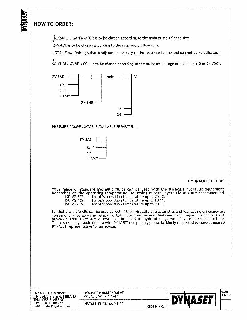
HOWTO ORDER:
PRESSURE COMPENSATOR is to be chosen according to the main pump’s flange size.2LS-VALVE is to be chosen according to the required oil flow (CF).
NOTE! Flow limiting valve is adjusted at factory to the requested value and can not be re-adjusted
3.SOLENOID VALVE’s COIL is to be chosen according to the on-board voltage of a vehicle (12 or 24 VDC).
PV SAE j - 1/mm - j V
3/4,,I1 1/4”
0- 140
1224
PRESSURE COMPENSATOR IS AVAILABLE SEPARATELY:
PVSAE I3/4,,I”1 1/4”
HYDRAULIC FLUIDS
Wide range of standard hydrauLic fluids can be used with the DYNASET hydraulic equipment.Depending on the operating temperature, following mineral hydraulic oils are recommended:
ISO VG 32S for oil’s operation temperature up to 70 °C;ISO VG 46S for oil’s operation temperature up to 80 ~C;ISO VG 68S for oil’s operation temperature up to 90 ~C.
Synthetic and bio-oils can be used as well if their viscosity characteristics and Lubricating efficiency arecorresponding to above mineral oils. Automatic transmission fluids and even engine oils can be used,provided that they are allowed to be used in hydraulic system of your carrier machine.To use special hydraulic fluids a with DYNASET equipment, please be kindly requested to contact nearestDYNASET representative for an advice.
DYNASET OY, Menotie 3 DYNASET PRIORITY VALVE II FIN-33470 Ylöjärvi, FINLAND I PV SAE 3/4” - 1 1/4” I I DY~A5ET I PAGEI Tel.: ÷358 3 3488200 I I I
~ Il/ 12~
I Fax ÷358 3 3488222 INSTALLATION AND USE Ij E-mail: info @dynaset.com 050224 I KL

SAFETY PRECAUTIONSThe pressure in hydraulic fluid circuit is considerably high. Thereat the technical condition of yourequipment should be under constant scrutiny. Especially couplings, valves and hoses should be maintainedtight and clean as welt as kept under constant observation.Hydraulic leakages must be rectified immediately to avoid injuries caused by pressure and hot oil blowouts.Follow all your local safety instructions related to the high pressure hydraulics.Hydraulic system of a carrier machine should be maintained according to the service program.In order to exclude possible accidents, it is not allowed to clean or inspect PV SAE valve when hydraulicfluid circuit is pressurised. Prior to any cleaning, inspection and service hydraulic system of your carriermachine must be stopped and all hydraulic fluid circuits dissipated.Always wear appropriate clothing and safety equipment such as goggles, ear protection and safety shoesat all times when maintaining the PV SAE valve. Beware of machinery parts warmed by hot hydraulic oil.
AN EXTERME CLEANLINESS MUST BE MAINTAINED WHEN CARRYING OUT ANY SERVICE DISSASSEMBLINGOR REPAIR OF HRN-TOOL AND HYDRAULIC SYSTEM. THIS IS CRUCIAL TO ENSURE SAFE, RELIABLE ANDLONG-LIFE OPERATION OF YOUR EQUIPMENT.
Operators and maintenance personnel must always comply with local safety regulations and precautionsin order to close out the possibility of damages and accidents.All installation and service of both hydraulic and electric equipment must be performed by qualified andexperienced personnel only.
WARRANTY
DYNASET products are warranted against defects in materials and workmanship for a period of 6 (six)months from the date of purchase. Exceptions are parts subject to normal wear and tear, such as sealsand other parts that become worn through normal use of the unit.Warranty covers detective parts solely. Expenditure incidental to shipping and replacement are notcovered by present warranty.The warranty is void if product has been modified, provided with parts other than original or misused.
DYNASET OY, Menotie 3 DYNASET PRIORITY VALVE PAGEFIN-33470 Ytöjärvi, FINLAND PV SAE 3/4” - 1 1/4” 12/12Tel.: +358 3 3488200Fax ÷358 3 3488222 INSTALLATION AND USE ________________________
E-mail, info @dynaset.com 050224 I KL

DENECO
DYNASET LOAD SENSING VALVE
LSV 40LSV 60LSV 90LSV 150
GENSCO EQUIPMENT (1990) Inc. GENSCO AMERICA INC.53 Carlaw Avenue 5307 Dividend DriveToronto, Canada Decatur, Georgia 30035M4M 2R6 Phone: 770-808-8711Phone: 416-465-7521 Fax: 770-808-8739Fax: 416-465-4489
Across USA Call 1-800-268-6797E Mail: info(d~cienscoepui~.comInternet: www penscoeciuio.com
Serving industry world wide since 1919

DYNASET LOAD SENSING VALVELSV 40
LSVI5O
DYNASET LSV LOAD SENSING VALVES ARE ESPECIALLY DESIGNED TORELIABLE INSTALLATION OF DYNASET HYDRAULIC GENERATOR TO AHYDRAULIC SYSTEM.
,,~ ~
Al ~ir
DYNASET LSV-VALVE ENABLES TO OPERATE YOUR DYNASET-UNIT SIMULTANEOUSLYWITH OTHER HYDRAULIC EXECUTORS.
DYNASET LSV-VALVE ENSURES THE NON-FLUCTUATING HYDRAULIC FLUID FLOW TOYOUR DYNASET-UNIT.
DYNASET LSV-VALVE IS DESIGNED TO OPERATE TOGETHER WITH HYDRAULIC PUMP’SCONTROL.
I DYNASET OY, Menotie 3 DYNASET LOAD SENSING VALVEI FIN-33470 Ytöjärvi, FINLAND I LSV 40 xx (pm - 12/24 V - LSV 150 xx (pm - 12/24 II TeL.: +358 3 3488200 I I ~ DY~ASET
1/7
I Fax +358 3 3488222 INSTALLATION AND USE I~ E-mail: info @dynaset.com 050530 I KL
LSV 60LSV 90
I
ENABLE EASY ANDCLOSED CENTRE

DYNASET LSV valve includes foLlowing components:1.2Solenoid valve 12/24V;1.3FLow Limiting valve.1.4Pressure relief valve
CONSTRUCTION I
VALVE MODEL p max Q CF, max * HYDRAULIC PORTS
bar 1/mm
LSV4O- xx Lpm-1 2/24 V 350 40LSV6O- xx lpm-12/24 V 350 60
~ CF-rate is adjusted at factory to the value specified by a customer
I
*4%
I DYhjASET LS VALVE
PAGES’~ DYNASET OY, Menotie 3 I DYNASET LOAD SENSING VALVE II FIN-33470 YLöjärvi, FINLAND I LSV 40 xx 1pm - 12/24 V - LSV 150 xx (pm - 12/24 I II Tel.: +358 3 3488200 I I I DYNASET~ 2f7~I Fax +358 3 3488222 INSTALLATION AND USE I I~ E-mail: info @dynaset.com 050530 I KL

00
DYNASET OY, Menotie 3 DYNASET LOAD SENSING VALVEI FIN-33470 YLöjarvi FINLAND I LSV 40 xx 1pm - 12/24 V - LSV 150 xx (pm - 12/24 I I DY~A5ET~ IPAGE~I TeL.: +358 3 3488200 I I I
V?7I Fax +358 3 3488222 INSTALLATION AND USE I I~ E-mail: info @dynaset.com 050530/ KL
I CONSTRUCTION II
VALVE MODEL p max
bar
LSV95 - xx Ipm-12/24 V 350
* CF-rate is adjusted at factory to the vaLue specified by a customer
HYDRAULIC PORTS
Se~:iø
0
IDYh~ASETI LS VALVE
LS
IP CF
II
L____

mi
0
DYNASET OY, Menotie 3FIN-33470 Ylojarvi, FINLANDTel.: +3583 3488200Fax +358 3 3488222E-mail: info @dynaset.com
DYNASET LOAD SENSING VALVELSV4Oxx 1pm- 12/24V LSV 150 xx (pm- 12/24
INSTALLATION AND USE050530 I KL
PAGE
DYI1A5ET~ h/i
I CONSTRUCTION III
HYDRAULIC PORTSVALVE MODEL p max Q CF, max *
bar 1/mm
LSVI5O-xxlpm-12/24V 350 150
* CF-rate is adjusted at factory to the value specified by a customer
e

INSTALLATION
BASIC INSTALLATION WITH SHUTTLE VALVE IN LS-LINE
The shuttLe vaLve to LS-Line is availabLefrom DYNASET Oy as an optionaL accessory.
AN INSTALLATION TO A SYSTEM WITH PARALLEL LS-CONNECTION (for reference only)
DYNASET OY, Menotie 3FIN-33470 YLöjärvi, FINLANDTeL.: +358 3 3488200Fax +358 3 3488222E-mail: info @dynaset.com
-=~- J:~-—~4f~~
______ HG
DVhIA CIT HMG~ HWG1
INSTALLATION AND USE
I DYNASET LOAD SENSING VALVE I PAGELSV 40 xx 1pm - 12/24 V - LSV 150 xx (pm - 12/24 I DY~~A5ET ~ “7
050530/KL

INSTALLATION /OPERATION
The complete controL is achieved by proper positioningthe hydrauLic pump’s swash plate to meet current fLowand pressure requirements. This is achieved by a pump’sregulator, hydraulic system’s controL valves and DYNASETLS-VALVE.
PRESSURE CUT-OFF SPRING
PRESSURE CUT-OFF SPOOL
THE DYNASET GENERATOR IS INOPERATION ALL OTHER EXECUTORS BEINGDISCONNECTED:The setting of the incorporated flow limitingvaLve (VR) , which operates in givenconditions as a flow sensor, rates thedischarge produced by a hydraULic pump,ensuring the constant Level of the pressuredifference L~p between pump’s outletpressure and pressure in LS-Line as well asconstant hydrauLic flow for the DYNASETgenerator.
III~9~!JJ—!’~~~ I••-4~
MAIN VALVE BLOCK
F~] ; ~ IL~ ___
LOAD SENSING SPOOL
CONTROL PISTON
SHUTILE VALVE(OPTIONAL)
1
I~5E7I
Li
INLETPRESSURE PISTON
L.J CASE DRAIN
I
OIL FLOW LIMITINGVALVE (VR),pressure compensated
S
Li
j~ LS-VALVE
~DY~ASET j~
HGHMGHWG
AUTOMATICFREQUENCY / ROTATION SPEED
CONTROL VALVE
__~___~1DY~ASET1]
WHEN THE DYNASET GENERATOR IS OPERATED ALONG WITH OTHER HYDRAULIC EXECUTORS:The pressure in LS control Line is defined by system’s maximum functional pressure, when the pump outletpressure LeveLs correspondingly. Flow limiting vaLve’s pressure compensation constraints the fLow increase,sequentiaL to the mentioned ~p rise, through the LS-vaLve, ensuring constant hydraulic fLow to the DYNASETgenerator.
I DYNASET OY, Menotie 3 DYNASET PRIORITY VALVEI FIN-33470 YLöjärvi, FINLAND I PV SAE 3/4” - 1 1/4” I II Tel.: +358 3 3488200 I I I DY~A5ET I PAGE
6/7
I Fax +358 3 3488222 INSTALLATION AND USE I I~ E-mail: info @dynaset.com 050530 I KL

HOWTO ORDER:0 i
LS-VALVE is to be chosen according to the required oil flow (CF).
NOTE Flow limiting valve is adjusted at factory to the requested value and can not be re-adjusted
2.SOLENOID VALVE’s COIL is to be chosen according to the on-board voltage of a vehicle (12 or 24 VDC).
LSVI I j V
406095
150 0-150
HYDRAULIC FLUIDS
Wide range of standard hydraulic fluids can be used with the DYNASET hydraulic equipment.Depending on the operating temperature, following mineral hydraulic oils are recommended:
ISO VG 32S for oil’s operation temperature up to 70 °C;ISO VG 46S for oil’s operation temperature up to 80 °C;ISO VG 68S for oil’s operation temperature up to 90 °C.
Synthetic and bio-oils can be used as well if their viscosity characteristics and lubricating efficiency arecorresponding to above mineral oils. Automatic transmission fluids and even engine oils can be used,provided that they are allowed to be used in hydraulic system of your carrier machine.To use special hydraulic fluids a with DYNASET equipment, please be kindly requested to contact nearestDYNASET representative for an advice.
SAFETY PRECAUTIONSThe pressure in hydraulic fluid circuit is considerably high. Thereat the technical condition of yourequipment should be under constant scrutiny. Especially couplings, valves and hoses should be maintainedtight and clean as well as kept under constant observation.Hydraulic leakages must be rectified immediately to avoid injuries caused by pressure and hot oil blowouts.Follow all your local safety instructions related to the high pressure hydraulics.Hydraulic system of a carrier machine should be maintained according to the service program.In order to exclude possible accidents, it is not altowed to clean or inspect LSV-vatve when hydraulic fluidcircuit is pressurised. Prior to any cleaning, inspection and service hydraulic system of your carrier machinemust be stopped and all hydraulic fluid circuits dissipated.Always wear appropriate clothing and safety equipment such as goggles, ear protection and safety shoesat alt times when maintaining the LSV-valve. Beware of machinery parts warmed by hot hydraulic oil.
AN EXTERME CLEANLINESS MUST BE MAINTAINED WHEN CARRYING OUT ANY SERVICE DISSASSEMBLINGOR REPAIR OF LSV-VALVE AND HYDRAULIC SYSTEM. THIS IS CRUCIAL TO ENSURE SAFE, RELIABLE ANDLONG-LIFE OPERATION OF YOUR EQUIPMENT.
Operators and maintenance personnel must always comply with local safety regulations and precautionsin order to close out the possibility of damages and accidents.All installation and service of both hydraulic and electric equipment must be performed by qualified andexperienced personnel only.
WARRANTY
DYNASET products are warranted against defects in materials and workmanship for a period of 6 (six)months from the date of purchase. Exceptions are parts subject to normal wear and tear, such as sealsand other parts that become worn through normal use of the unit.Warranty covers detective parts solely. Expenditure incidental to shipping and replacement are not coveredby present warranty.The warranty is void if product has been modified, provided with parts other than original or misused.
DYNASET OY, Menotie 3 DYNASET PRIORITY VALVEI FIN-33470 Ytöjärvi, FINLAND I PV SAE 314” - 1 1/4” I I DY~A5ET I PAGE]I TeL: +358 3 3488200 I I I
~7I7
I Fax +358 3 3488222 INSTALLATION AND USE I I~ E-mail: info @dynaset.com 050530 I KL

GENECO
DYNASET FLOW LIMITERS
VR 50VR 95VRD 180
GENSCO EQUIPMENT (1990) Inc. GENSCO AMERICA INC.53 Carlaw Avenue 5307 Dividend DriveToronto, Canada Decatur, Georgia 30035M4M 2R6 Phone: 770-808-8711Phone: 416-465-7521 Fax: 770-808-8739Fax: 416-465-4489
Across USA Call 1-800-268-6797E Mail: info~kienscoeciuip.comInternet: www.penscoepuic.com
Serving industiy world wide since 1919

I
DYNASET FLOW LIMITERSVR5OVR95VRD 180
DYNASET VR FLOW LIMITERS ARE ESPECIALLY DESIGNED TO ACHIEVE RELIABLE HYDRAULICFLUID FLOW CONTROL IN ORDER TO KEEP FLOW CONSTANT, ENSURING PROPER OPERATIONOF DYNASET HYDRAULIC GENERATOR.
DYNASET PRESSURE COMPENSATED OIL FLOW LIMITER FOR IN-LINE INSTALLATIONprovides extra fast control of hydraulic fLuid fLow.
DYNASET OIL FLOW LIMITER is especially designed for use in LS-hydrautic systems withseveral simuLtaneously running executors.
DYNASET OIL FLOW LIMITER is an essential part of a DYNASET PRIORITY VALVE whichenables the trouble-free operation of a DYNASET generator in open centre hydraulicsystems.
Outlet flow rate is independent of the pressure and viscosity.The flow rate is determined by a fixed measuring sensor. DYNASET FLOW LIMITER ispre-adjusted at factory.
DYNASET OY, Menotie 3 DYNASET FLOW LIMITERS PAGESFIN-33470 Ylöjärvi, FINLAND VR I VRD 1 I 6TeL.: +358 3 3488200Fax +358 3 3488222 INSTALLATION AND USE _________________________E~maiI. info @dynaset.com 050610/ KL

200
100
90
I I I
I I I
I I I
I: ~ ••_~.~~~:; .‘:~
I 1~~ct270
60
0 100 200 300 350
DYNASET pressure compensated flow Limiters are fixedorifice vaLves with back-up differential pressurecompensator for hydraulic systems.The differentiaL pressure compensator consists of acontrol spool, spring, controL opening and the adjustmentscrew to adjust the control pressure differentiaL. Theoil flow sensor determines the flow adjustment range.The fLow from 1 to 2 in the valve is specified by apressure drop in the oiL flow sensor. The compensatingspool moves into a controL position which correspondsto the equiLibrium between the force reLated to thepressure drop via the oil flow sensor on the other handand the spring force on the other.As the fLow rate increases, e. g. increasing pressuredrop, the diameter of the controL opening is reducedin accordance with the increased pressure drop, untila force equLibrium exists once more.Due to the continuous adjustment of the compensatingspool in accordance with the prevailing pressure drop,a constant fLow in control direction 1-2 is ensured.
LOCKING NUT
ADJUSTMENT SCREW
CONTROL OPENING
I1~ ~lI~[c
CONTROL SPOOL
OIL FLOW SENSOR
BASIC CONSTRUCTION AND FUNCTION
The basic DYNASET FLOW LIMITER corresponds to the glow limiting cartridge valve, which can be fitted intodifferent controL bLocks and housings. Depending on a flow Limiter’s capacity, the compLete valve includesan appropriate housing.
I = FREE FLOW.
2 = CONTROLLED FLOW.
FLOW RATE (Q) DEPENDENCY ON PRESSURE
SIMPLIFIED SYMBOL DETAILED SYMBOL
iF 2.o ~ ~
___L/~\~.
COIL FLOW SENSOR) (PRESSURE COMPENS~~D
-~ Qmax/VRD 180
C
E
0’
-ø~Qmax/VR95CIn
>
MEASURED AT:x•0EdA
50
40
30
20
10
;‘....
- ~
• U,
• >
I°• C
- _...Ec
\? =72mm2/sec.
toil=30 °C.
- .* Qmin/VR95
p [bar]
I DYNASET OY, Menotie 3 I DYNASET FLOW LIMITERS I~ FIN-33470 YLöjärvi, FINLAND VR I VRD I I~ TeL.: +358 3 3488200 I I I DYNASET ‘PAGES’
2/6
I Fax +358 3 3488222 INSTALLATION AND USE I I~ E-mail: info @dynaset.com 050610/ KL

I
DYNASET OY, Menotie 3FIN-33470 Ytöjärvi, FINLANDTeL.: +358 3 3488200Fax +358 3 3488222E-mail: info @dynaset.com
BASIC CARTRIDGE INSTALLATION DIMENSIONS
VALVE CARTRIDGEFOR:
STOCKNUMBER
p max
bar
VR5OPK-1/2-xx 1pm 13004280 350VR95PK-3/4-xx 1pm 13004430 350
* CF-rate is adjusted at factory to the value specified by a customer.
Q CF. max *
L/min
5095
DIMENSIONS
H,mm G
37 BSP 1/2”51 BSP 3/4”
WEIGHT
g
49112
T)
TORQUET, Nm
VR 5OPK-1/2- xx 1pm 8 - 12VR 95PK- 3/4-xx 1pm 12- 18
e mm
VALVE CARTRIDGEFOR:
G
DIMENSIONS, mm
a mm b mm C mm d mm e mm h max
VR 5OPK-1/2- xx 1pm BSP 1/2” 40 15 37 18 10 2,5
VR 95PK-3/4- xx 1pm BSP 3/4” 51 24 51 24 12 2,5
The instalLation dimensions listed above are minimum values for pipe threads and male threadsto DIN 3852.

AVAILABLE HOUSINGS
p
BSP 1/2”
BSP 3/4”
Housing for VRDSTOCK NUMBER:
I8OPK-1”-xx 1pm07030797
DYNASET OY, Menotie 3FIN-33470 Ylojarvi, FINLANDTel.: +3583 3488200Fax +358 3 3488222E-mail: info @dynaset.com
I PAGE
UDYNASET~ 14/61050610 /KL
HOUSING FOR: STOCKNUMBER
VR 95PK- 3/4-xx 1pm
VR 5OPK-1/2- xx 1pm
CF
13004400
mm
13004460
Lmm
BSP 1/2” 82
BSP 3/4” 98
SWmm
WEIGHTkg
14 27 0,2
16 36 0,43
IDY~A5ETI VRp CF
I~
(yR 95PK
0pCF
0
BSP IBSP I”
11
r1~1i7WEIGHT 3,3 kg
p

The flow tuning can onLy be made when thevalve is taken out from its housing. In orderto change the fLow rate setting the Lockingnut has to be Loosened. By turning theadjustment screw in the appropriate direction(+ increase flow; - reduce flow), the fLow rateis tuned.SubsequentLy, the adjustment screw is securedby means of the Locking nut.
NOTE!The edging on both sides of the vaLve bodyLimits the adjustment range. Do not force theLocking nut past the adjustment Limit.
cb4
I—T - TUNING RANGE: +For VR 50: T = approx. 3 mmFor VR 95 T = approx. 3 mm
FACTORY SETTING:
The adjustment screw is set at factoryapproximiteLy to the middle of the tuning range,which is about 2- 10 % of the pre-adjustednominaL rate of the flow limiter.
HYDRAULIC DETAILS
NOMINAL PRESSURE: p~ 350 bar on aLL ports;
WORKING PRESSURE RANGE:~ p = the required controL pressure differentiaLp1 - p~. If the differentiaL pressure is lower, the valveoperates as a speed control vaLve. p1 max = 350 bar;
HYDRAULIC FLUID TEMPERATURE RANGE:tmin= —20CC;tmax= +80C;
VISCOSITY RANGEVmin = 2,8 mm2/sec;‘Vmax= 380 mm2/sec.
.1 ON-SITE TUNING
I
~r-1
~ F, ‘VIII, __________
1L’ __
•. —L~ r~
-~+
FLOW RATE
I DYNASET OY, Menotie 3 DYNASET FLOW LIMITERS II FIN-33470 YLöjärvi, FINLAND I VR I VRD I DY~A5ET I PAGE~ TeL.: +358 3 3488200 I I I
5/6
~ Fax +358 3 3488222 INSTALLATION AND USE I I~ E-mail: info @dynaset.com 050610 I KL

HYDRAULIC FLUIDS:
Wide range of standard hydrauLic fLuids can be used with the DYNASET hydrauLic equipment.Depending on the operating temperature, folLowing mineral hydraulic oiLs are recommended:
ISO VG 325 for oiL’s operation temperature up to 70 ‘C;ISO VG 46S for oiL’s operation temperature up to 80 ‘C;ISO VG 685 for oft’s operation temperature up to 90 ‘C.
Synthetic and bio-oiLs can be used as well if their viscosity characteristics and Lubricating efficiency arecorresponding to above mineraL oiLs. Automatic transmission fluids and even engine oils can be used, providedthat they are aLLowed to be used in hydrauLic system of your carrier machine.To use speciaL hydrauLic fluids a with DYNASET equipment, please be kindLy requested to contact nearestDYNASET representative for an advice.
HOW TO ORDER:
VR / VRD FLOW LIMITER is to be chosen according to the required oil flow (CF).
VR I - I - 1/mm VRD I8OPK-1- I - I/mm
5OPK- 1/2-95PK-3/4- 5-95 97-180
SAFETY PRECAUTIONS
The pressure in hydraulic fluid circuit is considerabLy high. Thereat the technical condition of yourequipment should be under constant scrutiny. EspecialLy coupLings, valves and hoses should be maintainedtight and clean as welL as kept under constant observation.Hydraulic Leakages must be rectified immediately to avoid injuries caused by pressure and hot oil blowouts.FoLLow all your LocaL safety instructions related to the high pressure hydrauLics.HydrauLic system of a carrier machine should be maintained according to the service program.In order to excLude possibLe accidents, it is not aLLowed to cLean or inspect VR/VRD-VALVE when hydraulicfLuid circuit is pressurised. Prior to any cLeaning, inspection and service hydrauLic system of your carriermachine must be stopped and aLl hydrauLic fluid circuits dissipated.Always wear appropriate cLothing and safety equipment such as goggles, ear protection and safety shoesat aLL times when maintaining the VR/VRD-VALVE. Beware of machinery parts warmed by hot hydraulicoil.
AN EXTER~ME CLEANLINESS MUST BE MAINTAINED WHEN CARRYING OUT ANY SERVICE DISSASSEMBLINGOR REPAIR OF LSV-VALVE AND HYDRAULIC SYSTEM. THIS IS CRUCIAL TO ENSURE SAFE, RELIABLE ANDLONG-LIFE OPERATION OF YOUR EQUIPMENT.
Operators and maintenance personnel must aLways comply with local safety regulations and precautionsin order to close out the possibility of damages and accidents.ALL instaLLation and service of both hydraulic and electric equipment must be performed by quaLified andexperienced personnel only.
WARRANTY
DYNASET products are warranted against defects in materials and workmanship for a period of 6 (six)months from the date of purchase. Exceptions are parts subject to normal wear and tear, such as sealsand other parts that become worn through normal use of the unit.Warranty covers detective parts soleLy. Expenditure incidentaL to shipping and replacement are notcovered by present warranty.The warranty is void if product has been modified, provided with parts other than original or misused.
DYNASET OY, Menotie 3 I DYNASET FLOW LIMITERS I~ FIN-33470 Ylöjärvi, FINLAND I VR I VRD I I DY~ASET I PAGEi TeL.: +358 3 3488200 I I I
6/6
I Fax +358 3 3488222 INSTALLATION AND USE I~ E-mail: info @dynaset.com 050610/ KL


![FK r kR 3FL w Hiszpaniiyadda.icm.edu.pl/yadda/element/bwmeta1.element... · 6/2013 11: u plq÷ r odw rg xuxfkrplhqld slhuzv]hm olqll gx qhm su÷gnr 3fl z +lv]sdqll nwÐud rehfqlh](https://img.pdfslide.net/doc/110x75/5e839e4f46ffc642bc7cb22a/fk-r-kr-3fl-w-62013-11-u-plq-r-odw-rg-xuxfkrplhqld-slhuzvhm-olqll-gx-qhm-sugnr.jpg)


![Inhaltsverzeichnis · [ I ] SAE-Flansche (ISO 6162) / SAE-flanges (ISO 6162) Seite / Page SAE-Flanschhälften / SAE-split flange halves FH-... 1 SAE-Vollflansch / SAE-flange](https://img.pdfslide.net/doc/110x75/5b1675127f8b9a546d8c0fe1/inhaltsverzeichnis-i-sae-flansche-iso-6162-sae-flanges-iso-6162-seite.jpg)