Embed Size (px)
Citation preview
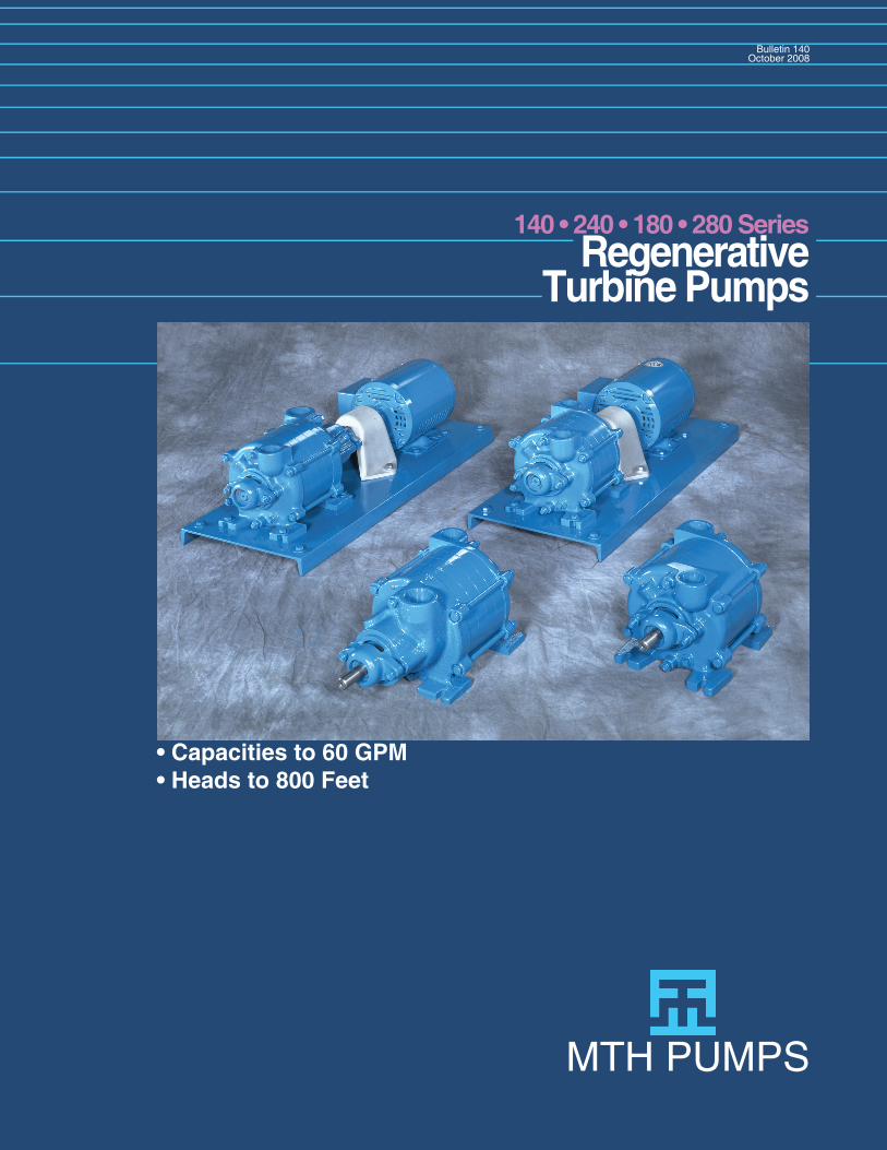
• Capacities to 60 GPM• Heads to 800 Feet
RegenerativeTurbine Pumps
140 • 240 • 180 • 280 Series
MTH PUMPS
Bulletin 140October 2008
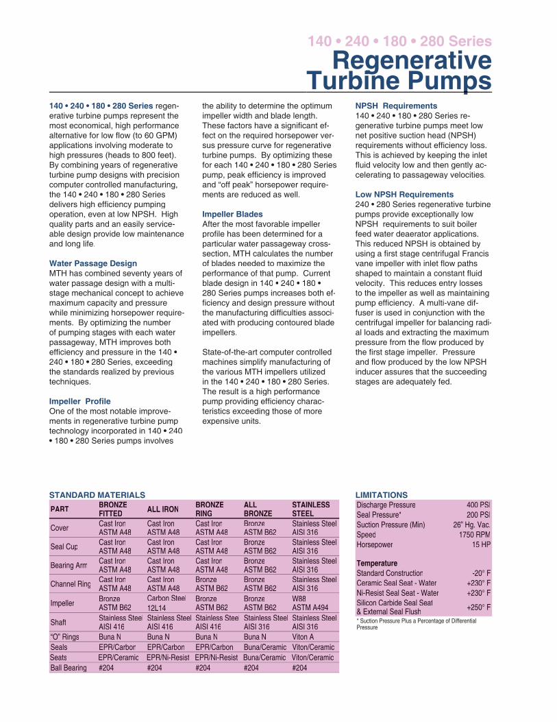
the ability to determine the optimum impeller width and blade length. These factors have a signifi cant ef-fect on the required horsepower ver-sus pressure curve for regenerative turbine pumps. By optimizing these for each 140 • 240 • 180 • 280 Series pump, peak effi ciency is improved and “off peak” horsepower require-ments are reduced as well.
Impeller BladesAfter the most favorable impeller profi le has been determined for a particular water passageway cross-section, MTH calculates the number of blades needed to maximize the performance of that pump. Current blade design in 140 • 240 • 180 • 280 Series pumps increases both ef-fi ciency and design pressure without the manufacturing diffi culties associ-ated with producing contoured blade impellers.
State-of-the-art computer controlled machines simplify manufacturing of the various MTH impellers utilized in the 140 • 240 • 180 • 280 Series. The result is a high performance pump providing effi ciency charac-teristics exceeding those of more expensive units.
NPSH Requirements140 • 240 • 180 • 280 Series re-generative turbine pumps meet low net positive suction head (NPSH) requirements without effi ciency loss. This is achieved by keeping the inlet fl uid velocity low and then gently ac-celerating to passageway velocities.
Low NPSH Requirements240 • 280 Series regenerative turbine pumps provide exceptionally low NPSH requirements to suit boiler feed water deaerator applications.This reduced NPSH is obtained by using a fi rst stage centrifugal Francis vane impeller with inlet fl ow paths shaped to maintain a constant fl uid velocity. This reduces entry losses to the impeller as well as maintaining pump effi ciency. A multi-vane dif-fuser is used in conjunction with the centrifugal impeller for balancing radi-al loads and extracting the maximum pressure from the fl ow produced by the fi rst stage impeller. Pressure and fl ow produced by the low NPSH inducer assures that the succeeding stages are adequately fed.
RegenerativeTurbine Pumps
140 • 240 • 180 • 280 Series
140 • 240 • 180 • 280 Series regen-erative turbine pumps represent the most economical, high performance alternative for low fl ow (to 60 GPM) applications involving moderate to high pressures (heads to 800 feet). By combining years of regenerative turbine pump designs with precision computer controlled manufacturing, the 140 • 240 • 180 • 280 Series delivers high effi ciency pumping operation, even at low NPSH. High quality parts and an easily service-able design provide low maintenance and long life.
Water Passage DesignMTH has combined seventy years of water passage design with a multi-stage mechanical concept to achieve maximum capacity and pressure while minimizing horsepower require-ments. By optimizing the number of pumping stages with each water passageway, MTH improves both effi ciency and pressure in the 140 • 240 • 180 • 280 Series, exceeding the standards realized by previous techniques.
Impeller Profi leOne of the most notable improve-ments in regenerative turbine pump technology incorporated in 140 • 240• 180 • 280 Series pumps involves
LIMITATIONSSTANDARD MATERIALS
PART BRONZEFITTED ALL IRON BRONZE
RINGALLBRONZE
STAINLESSSTEEL
Cover Cast IronASTM A48
Cast IronASTM A48
Cast IronASTM A48
BronzeASTM B62
Stainless SteelAISI 316
Seal Cup Cast IronASTM A48
Cast IronASTM A48
Cast IronASTM A48
BronzeASTM B62
Stainless SteelAISI 316
Bearing Arm Cast IronASTM A48
Cast IronASTM A48
Cast IronASTM A48
BronzeASTM B62
Stainless SteelAISI 316
Channel Ring Cast IronASTM A48
Cast IronASTM A48
BronzeASTM B62
BronzeASTM B62
Stainless SteelAISI 316
Impeller BronzeASTM B62
Carbon Steel12L14
BronzeASTM B62
BronzeASTM B62
W88ASTM A494
Shaft Stainless SteelAISI 416
Stainless SteelAISI 416
Stainless SteelAISI 416
Stainless SteelAISI 316
Stainless SteelAISI 316
“O” Rings Buna N Buna N Buna N Buna N Viton ASeals EPR/Carbon EPR/Carbon EPR/Carbon Buna/Ceramic Viton/CeramicSeats EPR/Ceramic EPR/Ni-Resist EPR/Ni-Resist Buna/Ceramic Viton/CeramicBall Bearing #204 #204 #204 #204 #204
Discharge Pressure 400 PSISeal Pressure* 200 PSISuction Pressure (Min) 26” Hg. Vac.Speed 1750 RPMHorsepower 15 HP
TemperatureStandard Construction -20° FCeramic Seal Seat - Water +230° FNi-Resist Seal Seat - Water +230° FSilicon Carbide Seal Seat& External Seal Flush +250° F
* Suction Pressure Plus a Percentage of Differential Pressure
Turbine Pumps
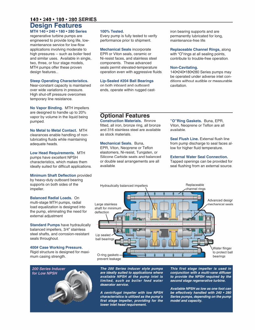
This first stage impeller is used in conjunction with a multi-vane diffuser to provide the NPSH required by the second stage regenerative turbine.
Available NPSH as low as one foot can be effectively handled with 240 • 280 Series pumps, depending on the pump model and capacity.
Design Features
The 200 Series inducer style pumps are ideally suited to applications where available NPSH at the pump inlet is limited, such as boiler feed water deaerator service.
A centrifugal impeller with low NPSH characteristics is utilized as the pump’s fi rst stage impeller, providing for the lower inlet head requirement.
140 • 240 • 180 • 280 SERIES
Hydraulically balanced impellers
Lip sealedball bearings
Large stainless shaft for minimum defl ection
Hydraulically balanced impellers
200 Series Inducerfor Low NPSH
Water fl inger Water fl inger to protect ball bearings
Advanced designmechanical seals
Replaceablechannel rings
O-ring gasketsprevent leakage
100% Tested.Every pump is fully tested to verify performance prior to shipment.
Mechanical Seals incorporate EPR or Viton seals, ceramic or Ni-resist faces, and stainless steel components. These advanced seals permit elevated-temperature operation even with aggressive fl uids.
Lip-Sealed #204 Ball Bearings on both inboard and outboard ends, operate within rugged cast-
”O”Ring Gaskets. Buna, EPR, Viton, Neoprene or Tefl on are all available.
Seal Flush Line. External fl ush line from pump discharge to seal faces al-low for higher fl uid temperature.
External Water Seal Connection. Tapped openings can be provided for seal fl ushing from an external source.
MTH 140 • 240 • 180 • 280 Seriesregenerative turbine pumps are engineered to provide long life, low-maintenance service for low-fl ow applications involving moderate to high pressures -- such as boiler feed and similar uses. Available in single, two, three, or four stage models, MTH pumps offer these proven design features...
Steep Operating Characteristics. Near-constant capacity is maintained over wide variations in pressure. High shut-off pressure overcomes temporary line resistance.
No Vapor Binding. MTH impellers are designed to handle up to 20% vapor by volume in the liquid being pumped.
No Metal to Metal Contact. MTH clearances enable handling of non-lubricating fl uids while maintaining adequate heads.
Low Head Requirements. MTH pumps have excellent NPSH characteristics, which makes them ideally suited for diffi cult applications.
Minimum Shaft Defl ection provided by heavy-duty outboard bearing supports on both sides of the impeller.
Balanced Radial Loads. On multi-stage MTH pumps, radial load equalization is designed into the pump, eliminating the need for external adjustment
Standard Pumps have hydraulically balanced impellers, 3/4” stainless steel shafts, and corrosion-resistant seals throughout.
400# Case Working Pressure.Rigid structure is designed for maxi-mum casing strength.
Optional FeaturesConstruction Materials. Bronze fi tted, all iron, bronze ring, all bronze and 316 stainless steel are available as stock materials.
Mechanical Seals. Buna, EPR, Viton, Neoprene or Tefl on elastomers, Ni-resist, Tungsten, or Silicone Carbide seats and balanced or double seal arrangements are all available.
iron bearing supports and are permanently lubricated for long, maintenance-free life.
Replaceable Channel Rings, along with “O”rings at all sealing points, contribute to trouble-free operation.
Non-Cavitating.140•240•180•280 Series pumps may be operated under adverse inlet con-ditions without audible or measurable cavitation.
140 • 180 SeriesThe contractor shall furnish (and install as shown on the plans) an MTH Turbofl ex regenerative type pump model_________ size______ of (BRONZE FITTED) (BRONZE RING) (ALL IRON) (ALL BRONZE) (316 STAINLESS STEEL) construction. Each pump shall have a capacity of ____GPM when operating at a total head of _______feet at the specifi ed temperature, viscosity, specifi c gravity, and with _______feet NPSHA. The maximum speed shall not exceed 1750 RPM. Pump shall be of the vertically split case design with removable bearing housings and is to be furnished with mechanical seals. The channel rings shall be replaceable external type. The suction connection shall be _____” NPT located in the top vertical position and be cast separately from the discharge. The discharge shall be ______” NPT in the top vertical position and the pump shall be self-venting. The impeller(s) shall be located on a stainless steel shaft between sealed grease lubricated ball bearings. The impeller(s) shall be hydraulically self positioning with no external adjustment necessary. Each pump shall be tested at the specifi ed capacity and head prior to shipment. The pump shall be mounted on a steel baseplate, fl exibly coupled with aluminum guard to a ___HP ____phase _____Hertz
______volt _____RPM horizontal (DRIP-PROOF) (TOTALLY ENCLOSED) (EXPLOSION PROOF) motor. The motor is to be sized to prevent overloading at the highest head condition listed in the specifi cation.
240 • 280 SeriesThe contractor shall furnish (and install as shown on the plans) an MTH Turboflex low NPSH inducer style regenerative type pump model_________ size______ of (BRONZE FITTED) (BRONZE RING) (ALL IRON) (ALL BRONZE) (316 STAINLESS STEEL) construction. Each pump shall have a capacity of ____GPM when operating at a total head of _______feet at the specifi ed temperature, viscosity, specifi c gravity, and with _______feet NPSHA. The maximum speed shall not exceed 1750 RPM. Pump shall be low NPSHR inducer style design with a centrifugal Francis vane design impeller and a multi-vane diffuser for balancing radial loads. Pump shall be of the vertically split case design with removable bearing housings and is to be furnished with mechanical seals. The channel rings shall be replaceable external type. The suction connection shall be _____” NPT located in the top vertical position and be cast separately from the discharge. The discharge shall be ______”
NPT in the top vertical position and the pump shall be self-venting. The impeller(s) shall be located on a stainless steel shaft between sealed grease lubricated ball bearings. The impeller(s) shall be hydraulically self positioning with no external adjustment necessary. Each pump shall be tested at the specifi ed capacity and head prior to shipment. The pump shall be mounted on a steel baseplate, fl exibly coupled with aluminum guard to a ___HP ___phase _____Hertz ______volt _____RPM horizontal (DRIP-PROOF) (TOTALLY ENCLOSED) (EXPLOSION PROOF) motor. The motor is to be sized to prevent overloading at the highest head condition listed in the specifi cation.
Engineering Specifi cations140 • 240 • 180 • 280 SERIES
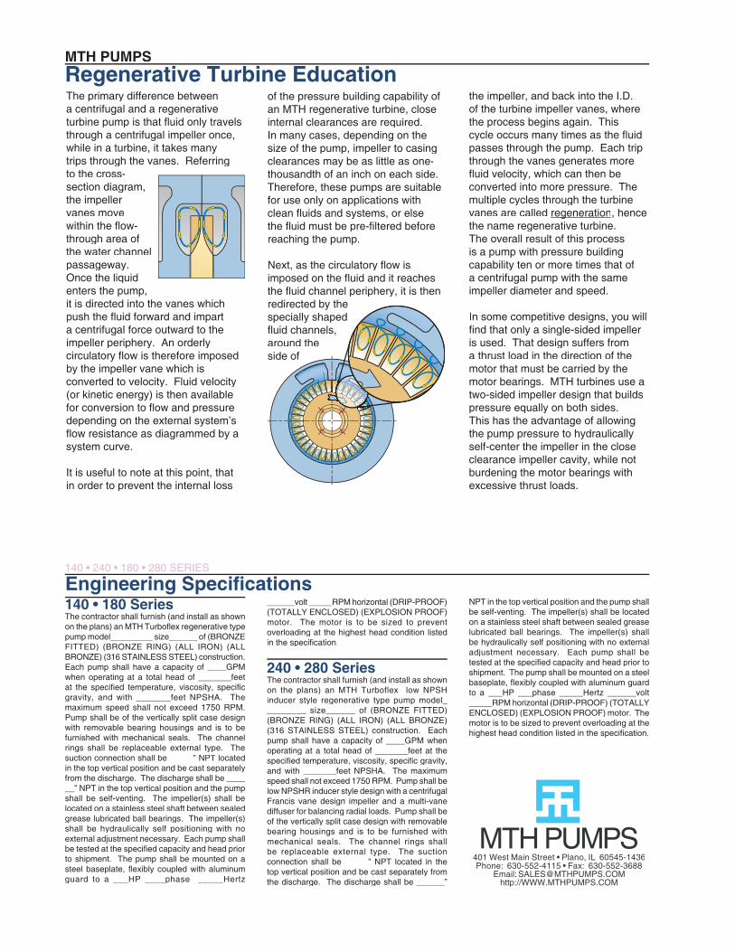
MTH PUMPSRegenerative Turbine EducationThe primary difference between a centrifugal and a regenerative turbine pump is that fl uid only travels through a centrifugal impeller once, while in a turbine, it takes many trips through the vanes. Referring to the cross-section diagram, the impeller vanes move within the fl ow-through area of the water channel passageway. Once the liquid enters the pump, it is directed into the vanes which push the fl uid forward and impart a centrifugal force outward to the impeller periphery. An orderly circulatory fl ow is therefore imposed by the impeller vane which is converted to velocity. Fluid velocity (or kinetic energy) is then available for conversion to fl ow and pressure depending on the external system’s fl ow resistance as diagrammed by a system curve.
It is useful to note at this point, that in order to prevent the internal loss
of the pressure building capability of an MTH regenerative turbine, close internal clearances are required. In many cases, depending on the size of the pump, impeller to casing clearances may be as little as one-thousandth of an inch on each side. Therefore, these pumps are suitable for use only on applications with clean fl uids and systems, or else the fl uid must be pre-fi ltered before reaching the pump.
Next, as the circulatory fl ow is imposed on the fl uid and it reaches the fl uid channel periphery, it is then redirected by the specially shaped fl uid channels, around the side of
the impeller, and back into the I.D. of the turbine impeller vanes, where the process begins again. This cycle occurs many times as the fl uid passes through the pump. Each trip through the vanes generates more fl uid velocity, which can then be converted into more pressure. The multiple cycles through the turbine vanes are called regenerationregeneration, hence the name regenerative turbine. The overall result of this process is a pump with pressure building capability ten or more times that of a centrifugal pump with the same impeller diameter and speed.
In some competitive designs, you will fi nd that only a single-sided impeller is used. That design suffers from a thrust load in the direction of the motor that must be carried by the motor bearings. MTH turbines use a two-sided impeller design that builds pressure equally on both sides. This has the advantage of allowing the pump pressure to hydraulically self-center the impeller in the close clearance impeller cavity, while not burdening the motor bearings with excessive thrust loads.
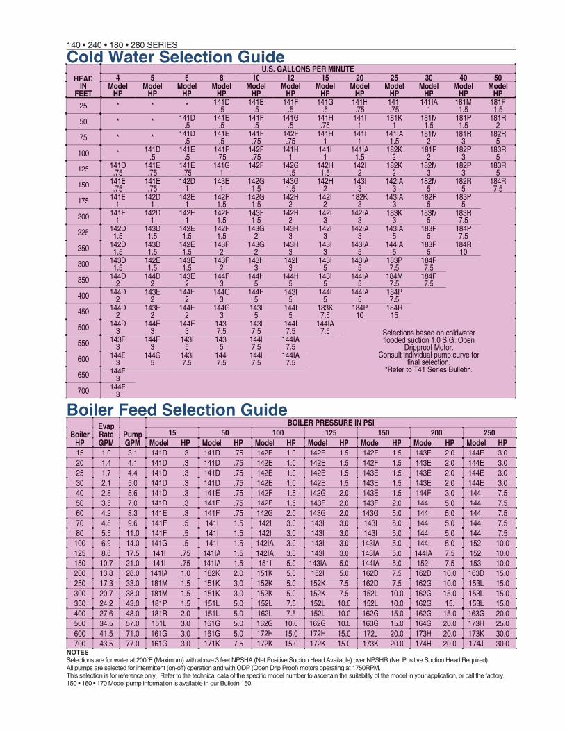
Cold Water Selection Guide140 • 240 • 180 • 280 SERIES
NOTESSelections are for water at 200°F (Maximum) with above 3 feet NPSHA (Net Positive Suction Head Available) over NPSHR (Net Positive Suction Head Required).All pumps are selected for intermittent (on-off) operation and with ODP (Open Drip Proof) motors operating at 1750RPM.This selection is for reference only.This selection is for reference only. Refer to the technical data of the specifi c model number to ascertain the suitability of the model in your application, or call the factory.150 • 160 • 170 Model pump information is available in our Bulletin 150.
Boiler Feed Selection GuideBoiler
HP
Evap Rate GPM
PumpGPM
BOILER PRESSURE IN PSI15 50 100 125 150 200 250
Model HP Model HP Model HP Model HP Model HP Model HP Model HP15 1.0 3.1 141D .3 141D .75 142E 1.0 142E 1.5 142F 1.5 143E 2.0 144E 3.020 1.4 4.1 141D .3 141D .75 142E 1.0 142E 1.5 142F 1.5 143E 2.0 144E 3.025 1.7 4.4 141D .3 141D .75 142E 1.0 142E 1.5 143E 1.5 143E 2.0 144E 3.030 2.1 5.0 141D .3 141D .75 142E 1.0 142E 1.5 143E 1.5 143E 2.0 144E 3.040 2.8 5.6 141D .3 141E .75 142F 1.5 142G 2.0 143E 1.5 144F 3.0 144I 7.550 3.5 7.0 141D .3 141F .75 142F 1.5 143F 2.0 143F 2.0 144I 5.0 144I 7.560 4.2 8.3 141E .3 141F .75 142G 2.0 143G 2.0 143G 5.0 144I 5.0 144I 7.570 4.8 9.6 141F .5 141I 1.5 142I 3.0 143I 3.0 143I 5.0 144I 5.0 144I 7.580 5.5 11.0 141F .5 141I 1.5 142I 3.0 143I 3.0 143I 5.0 144I 5.0 144I 7.5
100 6.9 14.0 141G .5 141I 1.5 142IA 3.0 143I 3.0 143IA 5.0 144I 5.0 152I 10.0125 8.6 17.5 141I .75 141IA 1.5 142IA 3.0 143I 3.0 143IA 5.0 144IA 7.5 152I 10.0150 10.7 21.0 141I .75 141IA 1.5 151I 5.0 143IA 5.0 144IA 5.0 152I 7.5 153I 10.0200 13.8 28.0 141IA 1.0 182K 2.0 151K 5.0 152I 5.0 162D 7.5 162D 10.0 163D 15.0250 17.3 33.0 181M 1.5 151K 3.0 152K 5.0 152K 7.5 162D 7.5 162G 10.0 153L 15.0300 20.7 38.0 181M 1.5 151K 3.0 152K 5.0 152K 7.5 152L 10.0 162G 15.0 153L 15.0350 24.2 43.0 181P 1.5 151L 5.0 152L 7.5 152L 10.0 152L 10.0 162G 15. 153L 15.0400 27.6 48.0 181R 2.0 151L 5.0 162L 7.5 152L 10.0 162G 15.0 162G 15.0 163G 20.0500 34.5 57.0 151L 3.0 161G 5.0 162G 10.0 162G 10.0 163G 15.0 164G 20.0 173H 25.0600 41.5 71.0 161G 3.0 161G 5.0 172H 15.0 172H 15.0 172J 20.0 173H 20.0 173K 30.0700 43.5 77.0 161G 3.0 171K 7.5 172K 15.0 172K 15.0 173K 20.0 174H 20.0 174J 30.0
HEADIN
FEET
U.S. GALLONS PER MINUTE4 5 6 8 10 12 15 20 25 30 40 50
Model HP
Model HP
Model HP
Model HP
Model HP
Model HP
Model HP
Model HP
Model HP
Model HP
Model HP
Model HP
25 * * * 141D.5
141E.5
141F.5
141G.5
141H.75
141I.75
141IA1
181M1.5
181P1.5
50 * * 141D.5
141E.5
141F.5
141G.5
141H.75
141I1
181K1
181M1.5
181P1.5
181R2
75 * * 141D.5
141E.5
141F.75
142F.75
141H1
141I1
141IA1.5
181M2
181R3
182R5
100 * 141D.5
141E.5
141F.75
142F.75
141H1
141I1
141IA1.5
182K2
181P2
182P3
183R5
125 141D.75
141E.75
141E.75
141G1
142F1
142G1.5
142H1.5
142I2
182K2
182M3
182P3
183R5
150 141E.75
141E.75
142D1
143E1
142G1.5
143G1.5
142H2
143I3
142IA3
182M5
182R5
184R7.5
175 141E1
142D1
142E1
142F1.5
142G1.5
142H2
142I2
182K3
143IA3
182P5
183P5
200 141E1
142D1
142E1
142F1.5
143F1.5
142H2
142I3
142IA3
183K3
183M5
183R7.5
225 142D1.5
143D1.5
142E1.5
142F1.5
143G2
143H3
142I3
142IA3
143IA5
183P5
184P7.5
250 142D1.5
143D1.5
142E1.5
143F2
143G2
143H3
143I3
143IA5
144IA5
183P5
184R10
300 143D1.5
142E1.5
143E1.5
143F2
143H3
142I3
143I5
143IA5
183P7.5
184P7.5
350 144D2
144D2
143E2
144F3
144H5
144H5
143I5
144IA5
184M7.5
184P7.5
400 144D2
143E2
144E2
144G3
144H5
143I5
144I5
144IA5
184P7.5
450 144D2
143E2
144E2
144G3
143I5
144I5
183K7.5
184P10
184R15
500 144D3
144E3
144F3
143I7.5
143I7.5
144I7.5
144IA7.5 Selections based on coldwater
fl ooded suction 1.0 S.G. Open Dripproof Motor.
fl ooded suction 1.0 S.G. Open Dripproof Motor.
fl ooded suction 1.0 S.G. Open
Consult individual pump curve for Dripproof Motor.
Consult individual pump curve for Dripproof Motor.
fi nal selection.Consult individual pump curve for
fi nal selection.Consult individual pump curve for
*Refer to T41 Series Bulletin.
550 143E3
144E3
143I5
143I5
144I7.5
144IA7.5
600 144E3
144G5
143I7.5
144I7.5
144I7.5
144IA7.5
650 144E3
700 144E3
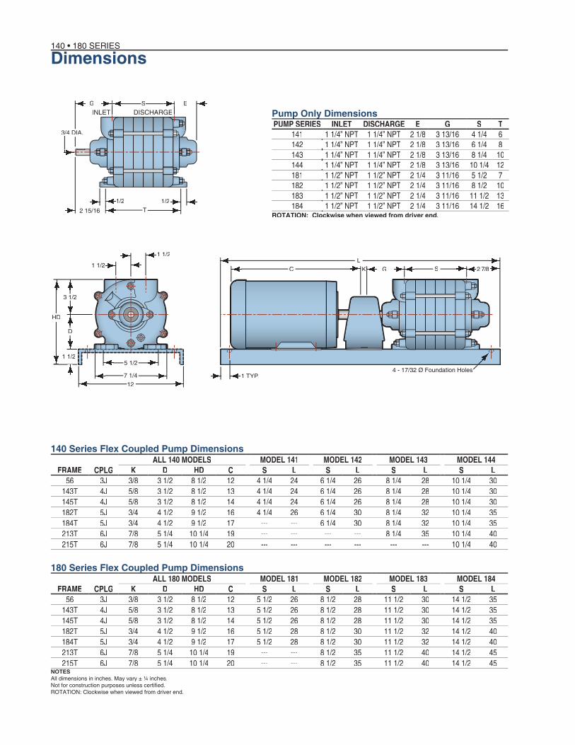
Dimensions140 • 180 SERIES
NOTESAll dimensions in inches. May vary ± ¼ inches.Not for construction purposes unless certifi ed.ROTATION: Clockwise when viewed from driver end.
ESG
1/2 1/22 15/16 T
3/4 DIA.
1 1/2
1 1/2
3 1/2
7 1/412
1 1/2
D
HD
5 1/2
2 7/8SGKL
C
Pump Only DimensionsPump Only DimensionsPump Only DimensionsPump Only DimensionsPUMP SERIES INLET DISCHARGE E G S T
141 1 1/4” NPT 1 1/4” NPT 2 1/8 3 13/16 4 1/4 6 142 1 1/4” NPT 1 1/4” NPT 2 1/8 3 13/16 6 1/4 8143 1 1/4” NPT 1 1/4” NPT 2 1/8 3 13/16 8 1/4 10144 1 1/4” NPT 1 1/4” NPT 2 1/8 3 13/16 10 1/4 12181 1 1/2” NPT 1 1/2” NPT 2 1/4 3 11/16 5 1/2 7182 1 1/2” NPT 1 1/2” NPT 2 1/4 3 11/16 8 1/2 10183 1 1/2” NPT 1 1/2” NPT 2 1/4 3 11/16 11 1/2 13184 1 1/2” NPT 1 1/2” NPT 2 1/4 3 11/16 14 1/2 16
ALL 140 MODELS MODEL 141 MODEL 142 MODEL 143 MODEL 144FRAME CPLG K D HD C S L S L S L S L
56 3J 3/8 3 1/2 8 1/2 12 4 1/4 24 6 1/4 26 8 1/4 28 10 1/4 30143T 4J 5/8 3 1/2 8 1/2 13 4 1/4 24 6 1/4 26 8 1/4 28 10 1/4 30145T 4J 5/8 3 1/2 8 1/2 14 4 1/4 24 6 1/4 26 8 1/4 28 10 1/4 30182T 5J 3/4 4 1/2 9 1/2 16 4 1/4 26 6 1/4 30 8 1/4 32 10 1/4 35184T 5J 3/4 4 1/2 9 1/2 17 --- --- 6 1/4 30 8 1/4 32 10 1/4 35213T 6J 7/8 5 1/4 10 1/4 19 --- --- --- --- 8 1/4 35 10 1/4 40215T 6J 7/8 5 1/4 10 1/4 20 --- --- --- --- --- --- 10 1/4 40
ALL 180 MODELS MODEL 181 MODEL 182 MODEL 183 MODEL 184FRAME CPLG K D HD C S L S L S L S L
56 3J 3/8 3 1/2 8 1/2 12 5 1/2 26 8 1/2 28 11 1/2 30 14 1/2 35143T 4J 5/8 3 1/2 8 1/2 13 5 1/2 26 8 1/2 28 11 1/2 30 14 1/2 35145T 4J 5/8 3 1/2 8 1/2 14 5 1/2 26 8 1/2 28 11 1/2 30 14 1/2 35182T 5J 3/4 4 1/2 9 1/2 16 5 1/2 28 8 1/2 30 11 1/2 32 14 1/2 40184T 5J 3/4 4 1/2 9 1/2 17 5 1/2 28 8 1/2 30 11 1/2 32 14 1/2 40213T 6J 7/8 5 1/4 10 1/4 19 --- --- 8 1/2 35 11 1/2 40 14 1/2 45215T 6J 7/8 5 1/4 10 1/4 20 --- --- 8 1/2 35 11 1/2 40 14 1/2 45
140 Series Flex Coupled Pump Dimensions
180 Series Flex Coupled Pump Dimensions
ROTATION: Clockwise when viewed from driver end.
INLET DISCHARGE
1 TYP.4 - 17/32 Ø Foundation Holes
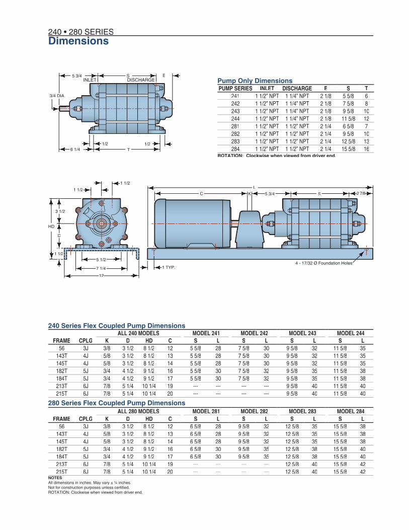
Dimensions240 • 280 SERIES
NOTESAll dimensions in inches. May vary ± ¼ inches.Not for construction purposes unless certifi ed.ROTATION: Clockwise when viewed from driver end.
ES5 3/4
1/2 1/26 1/4 T
3/4 DIA.
2 7/8S5 3/4KL
C1 1/2
1 1/2
3 1/2
5 1/2
7 1/4
12
1 1/2
D
HD
PUMP SERIES INLET DISCHARGE E S T241 1 1/2” NPT 1 1/4” NPT 2 1/8 5 5/8 6242 1 1/2” NPT 1 1/4” NPT 2 1/8 7 5/8 8243 1 1/2” NPT 1 1/4” NPT 2 1/8 9 5/8 10244 1 1/2” NPT 1 1/4” NPT 2 1/8 11 5/8 12281 1 1/2” NPT 1 1/2” NPT 2 1/4 6 5/8 7282 1 1/2” NPT 1 1/2” NPT 2 1/4 9 5/8 10283 1 1/2” NPT 1 1/2” NPT 2 1/4 12 5/8 13284 1 1/2” NPT 1 1/2” NPT 2 1/4 15 5/8 16
ALL 240 MODELS MODEL 241 MODEL 242 MODEL 243 MODEL 244FRAME CPLG K D HD C S L S L S L S L
56 3J 3/8 3 1/2 8 1/2 12 5 5/8 28 7 5/8 30 9 5/8 32 11 5/8 35143T 4J 5/8 3 1/2 8 1/2 13 5 5/8 28 7 5/8 30 9 5/8 32 11 5/8 35145T 4J 5/8 3 1/2 8 1/2 14 5 5/8 28 7 5/8 30 9 5/8 32 11 5/8 35182T 5J 3/4 4 1/2 9 1/2 16 5 5/8 30 7 5/8 32 9 5/8 35 11 5/8 38184T 5J 3/4 4 1/2 9 1/2 17 5 5/8 30 7 5/8 32 9 5/8 35 11 5/8 38213T 6J 7/8 5 1/4 10 1/4 19 --- --- --- --- 9 5/8 40 11 5/8 40215T 6J 7/8 5 1/4 10 1/4 20 --- --- --- --- 9 5/8 40 11 5/8 40
ALL 280 MODELS MODEL 281 MODEL 282 MODEL 283 MODEL 284FRAME CPLG K D HD C S L S L S L S L
56 3J 3/8 3 1/2 8 1/2 12 6 5/8 28 9 5/8 32 12 5/8 35 15 5/8 38143T 4J 5/8 3 1/2 8 1/2 13 6 5/8 28 9 5/8 32 12 5/8 35 15 5/8 38145T 4J 5/8 3 1/2 8 1/2 14 6 5/8 28 9 5/8 32 12 5/8 35 15 5/8 38182T 5J 3/4 4 1/2 9 1/2 16 6 5/8 30 9 5/8 35 12 5/8 38 15 5/8 40184T 5J 3/4 4 1/2 9 1/2 17 6 5/8 30 9 5/8 35 12 5/8 38 15 5/8 40213T 6J 7/8 5 1/4 10 1/4 19 --- --- --- --- 12 5/8 40 15 5/8 42215T 6J 7/8 5 1/4 10 1/4 20 --- --- --- --- 12 5/8 40 15 5/8 42
Pump Only Dimensions
240 Series Flex Coupled Pump Dimensions
280 Series Flex Coupled Pump Dimensions
ROTATION: Clockwise when viewed from driver end.
INLET DISCHARGE
1 TYP.4 - 17/32 Ø Foundation Holes

Bulletin 140October 2008
MTH PUMPS401 West Main Street • Plano, IL 60545-1436
Phone: 630-552-4115 • Fax: 630-552-3688Email: [email protected]://WWW.MTHPumps.com© 2008 MTH TOOL COMPANY