Embed Size (px)
Citation preview

1400/2000LV1400 | LV2000MF/MM
HYUNDAI WIA Ram Type Vertical Turning Center

Technical Leader ▶The CNC Turning Center LV1400/2000 Series, designed by Hyundai WIA with years of expertise and the latest technology, is designed to maximize productivity for machining large work.
LV1400 LV2000MF/MMMax. Swing mm(in) Ø1,450 (57.1″) Ø2,040 (80.3″)
Max. Turning Dia. mm(in) Ø1,400 (55.1″) Ø2,000 (78.7″)
Max. Turning Height mm(in) 850 (33.5″) 950 (37.4″)/1,700 (66.9″)
Table Size mm(in) Ø1,000 (39.4″) Ø1,600 (63″)
Max. Load Capacity kg(lb) 4,400 (9,700) 10,000 (22,046)
Spindle Speed r/min 492 258
Spindle Power kW(HP) 37/30 (50/40) 37/30 (50/40) [45/37 (60/50)]
Ram Size mm(in) 200×200 (7.9″×7.9″) 240×240 (9.4″×9.4″)
Travel (X/Z) mm(in) -50~+825 (-2″~+32.5″)/800 (31.5″) -250~+1,180 (-9.8~+46.5″)/915 (36″)
[ ] : Option
EXPERIENCE THE NEW TECHNOLOGY
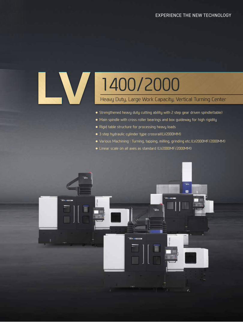
● Strengthened heavy duty cutting ability with 2 step gear driven spindle(table)
● Main spindle with cross roller bearings and box guideway for high rigidity
● Rigid table structure for processing heavy loads
● 3 step hydraulic cylinder type crossrail(LV2000MM)
● Various Machining : Turning, tapping, milling, grinding etc.(LV2000MF/2000MM)
● Linear scale on all axes as standard (LV2000MF/2000MM)
1400/2000Heavy Duty, Large Work Capacity, Vertical Turning Center

01LV
14
00
/2
00
0
Ram Head
Spindle & Table
ATC
- Ram Size LV1400 : 200×200mm (7.9″×7.9″) LV2000MF/MM : 240×240mm (9.4″x9.4″)- LV2000MM : 3 Step Crossrail
- Spindle Speed LV1400 : 492r/min LV2000MF/MM : 258r/min - Table Size LV1400 : Ø1,000mm (Ø39.4″) LV2000MF/MM : Ø1,600mm (Ø63″)
- No. of Tools LV1400 : 12 [16] EA LV2000MF/MM : 18 [16] EA- Tool Size (O.D/I.D) LV1400 : □32/□22mm (□1.3″/0.9″) LV2000MF/MM : □32/□25mm (□1.3″/1″)
BASIC STRUCTURE Highly Rigid Bed Structure for Heavy Duty Cutting Ram Type Vertical Turning Center

HIGH-PRECISION STRUCTUREHighly Stable Bed StructureLV1400/2000 is optimized for heavy duty cutting. Separate Bed Saddle structure made of cast iron minimizes vibration and thermal displacement
04+05
LV14
00/2
000
Ram
Typ
e Ve
rtic
al T
urni
ng C
ente
rEX
PER
IEN
CETH
E N
EW T
ECH
NO
LOGY
H
YUN
DAI W
IAM
ACH
INE
TOOL
Structure
GUIDEWAYHardened Plate Box GuidewayHighly rigid hardened plate attached box guideway increases rigidity and reduces vibration.Also, linear scales on all axes provided as standard enable precise machining. (LV1400 : Option)
Rigidity 10% UP compared to standard box guideway
3 Step Crossrail (LV2000MM)3 step hydraulic cylinder crossrail(250mm (9.8″x3) enables minimization of vibration and load by extending the length of the ram depending on the machining area. This unique design allows high performance in heavy duty operations.
BoxGuide
HardenedPlate
Floor Space (L×W)
LV1400 LV2000MF LV2000MM
3,685×3,276 mm 5,683×3,879 mm 5,683×3,937 mm
(145.1″×129″) (223.7″×152.7″) (223.7″×155″)
Travel (X/Z)
LV1400 LV2000MF/MM
-50~+825/800 mm -250~+1,180/915 mm
(-2″~+32.5″/31.5″) (-9.8~+46.5″/36″)
STRUCTURE FOR HEAVY CUTTING AND HIGH PRECISION

Heavy Duty, Large Work Capacity, Ram Type Vertical Turning Center
02 HEAVY DUTY CUTTING
LV
14
00
/2
00
0
HIGHLY RIGID TABLEThe maximum working height of 1,700mm (66.9″) - LV2000MM enables various workpiece machining.
Table Size
LV1400 LV2000MF/MM
Ø1,000 mm (39.4″) Ø1,600 mm (63″)
Max. Turning Height
LV1400 LV2000MF LV2000MM
850 mm (33.5″) 950 mm (37.4″) 1,700 mm (66.9″)
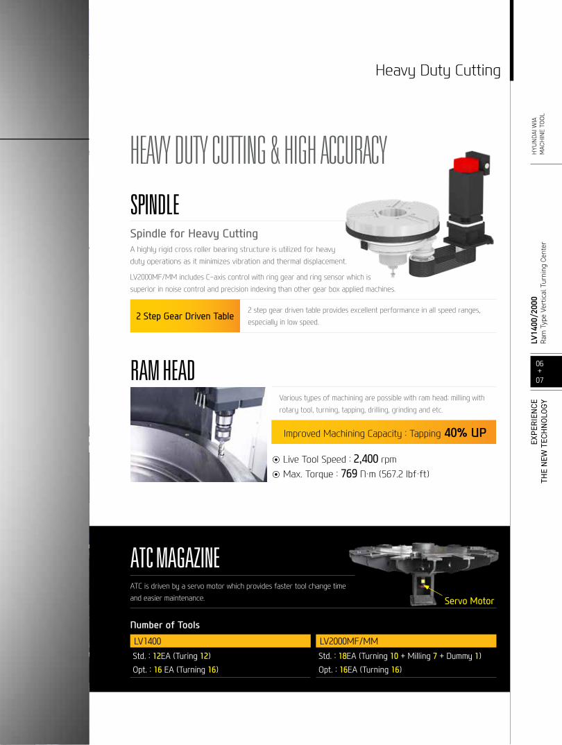
ATC MAGAZINEATC is driven by a servo motor which provides faster tool change time and easier maintenance.
Number of Tools
LV1400 LV2000MF/MMStd. : 12EA (Turing 12)Opt. : 16 EA (Turning 16)
Std. : 18EA (Turning 10 + Milling 7 + Dummy 1) Opt. : 16EA (Turning 16)
Servo Motor
SPINDLESpindle for Heavy CuttingA highly rigid cross roller bearing structure is utilized for heavy duty operations as it minimizes vibration and thermal displacement.
LV2000MF/MM includes C-axis control with ring gear and ring sensor which is superior in noise control and precision indexing than other gear box applied machines.
2 Step Gear Driven Table2 step gear driven table provides excellent performance in all speed ranges, especially in low speed.
06+07
LV14
00/2
000
Ram
Typ
e Ve
rtic
al T
urni
ng C
ente
rH
YUN
DAI W
IAM
ACH
INE
TOOL
Heavy Duty Cutting
EXPE
RIE
NCE
THE
NEW
TEC
HN
OLO
GY
RAM HEADVarious types of machining are possible with ram head; milling with rotary tool, turning, tapping, drilling, grinding and etc.
Improved Machining Capacity : Tapping 40% UP567.2
◉ Live Tool Speed : 2,400 rpm◉ Max. Torque : 769 N・m (567.2 lbf・ft)
HEAVY DUTY CUTTING & HIGH ACCURACY
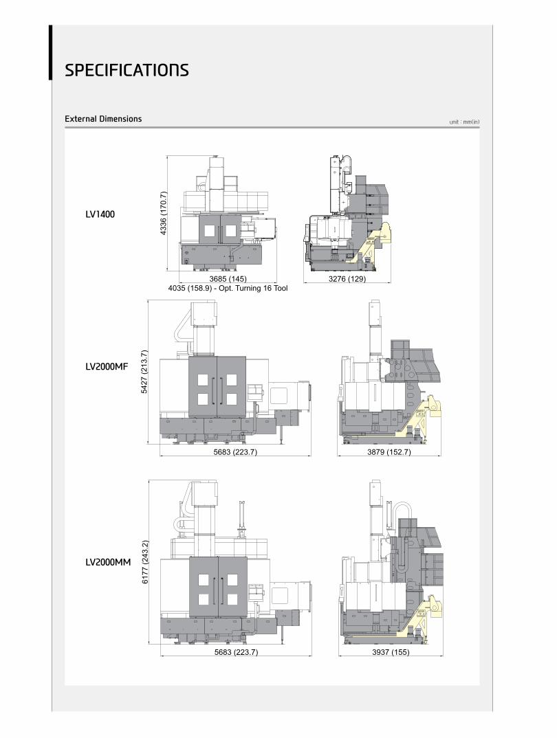
unit : mm(in)External Dimensions
6177
(243
.2)
5683 (223.7) 3937 (155)
LV2000MM
LV2000MF
5683 (223.7)
5427
(213
.7)
LV1400
4336
(170
.7)
3685 (145)4035 (158.9) - Opt. Turning 16 Tool
3276 (129)
3879 (152.7)
LV1400
LV2000MF
LV2000MM
SPECIFICATIONS

unit : mm(in)Tooling System
oS
A
B
STD.
B180(7.1)
A200(7.9)
Model
1084-40-203 32(1.3)
S
FACE HOLDER A
A
ØB oS
STD.
B120(4.7)
A300
(11.8)
Model
1084-40-204 80(3.1)
S
BORING BAR HOLDER
A
ØB oS
STD.
B120(4.7)
A300
(11.8)
Model
1084-40-205 32(1.3)
S
FACE HOLDER B
A
ØB oS
STD.
B120(4.7)
A300
(11.8)
Model
1084-40-206 32(1.3)
S
FACE HOLDER C
A
B oS
OPT.
B180(7.1)
A200(7.9)
Model
1084-40-210 32(1.3)
S
FACE HOLDER R
B
A
oS
EXTENSION BAR
OPT.
B142(5.6)
A400
(15.7)
Model
1084-40-209 32(1.3)
S
A
ØB oS
BORING BAR
STD.
B84
(3.3)
A300
(11.8)
Model
1084-40-208 22(0.9)
OPT.84(3.3)
400(15.7)1084-40-214 22
(0.9)
S
A
ØB oS
BORING BAR
STD.
B84
(3.3)
A300
(11.8)
Model
1084-40-207 22(0.9)
OPT.84(3.3)
200(7.9)1084-40-213 22
(0.9)
S
A
B oS
FACE HOLDER
OPT.
B142(5.6)
A305(12)
Model
1084-40-212 32(1.3)
S
A
B oS
OPT.
B180(7.1)
A200(7.9)
Model
1084-40-211 32(1.3)
S
FACE HOLDER L
LV1400
SPECIFICATIONS
08+09
LV14
00/2
000
Ram
Typ
e Ve
rtic
al T
urni
ng C
ente
rH
YUN
DAI W
IAM
ACH
INE
TOOL
EXPE
RIE
NCE
THE
NEW
TEC
HN
OLO
GY

unit : mm(in)Tooling System
A
B oS
A
ØB ØS
A
ØB oS
A
ØB oS
A
B oS
A
B oS
A
B
A
B oS
A
ØB oS
A
ØB oS
BORING BAR
A
B oS
FACE HOLDER-A
STD.
B240(9.4)
A219(8.6)
Model
1085-40-201 32(1.3)
S
FACE HOLDER-R
OPT.
B240(9.4)
A219(8.6)
Model
1085-40-206 32(1.3)
S
FACE HOLDER-L
OPT.
B240(9.4)
A219(8.6)
Model
1085-40-205 32(1.3)
S
BORING BAR HOLDER
STD.
B130(5.1)
A219(8.6)
Model
1085-40-204 90(3.5)
S
FACE HOLDER-B
OPT.
B130(5.1)
A219(8.6)
Model
1085-40-202 32(1.3)
S
FACE HOLDER-C
OPT.
B130(5.1)
A219(8.6)
Model
1085-40-203 32(1.3)
S
CONNECTION HOLDER
OPT.
B185(7.3)
A149(5.9)
Model
1085-40-209 -
S
EXTENSION BAR
OPT.
B142(5.6)
A408
(16.1)
Model
1085-40-207 32(1.3)
S
EXTENSION HOLDER
OPT.
B142(5.6)
A351
(13.8)
Model
1085-40-208 32(1.3)
S
BORING BAR
STD.
B94
(3.7)
A300
(11.8)
Model
1085-40-305 25(1)
OPT.94(3.7)
400(15.7)1085-40-307 25
(1)
S
STD.
B94
(3.7)
A300
(11.8)
Model
1085-40-306 25(1)
OPT.94(3.7)
400(15.7)1085-40-308 25
(1)
S
LV2000MF/MM
SPECIFICATIONS

unit : mm(in)Tooling System
LV2000MF/MM
Grinding Head
Angle Head
❖ These attachments are only applicable in mm unit.
90°
240
(9.4
)
240 (9.4)
118
(4.6
)11
8 (4
.6)
186
(7.3
)
186 (7.3)
4-C5
190
(7.5
)18
5 (7
.3)
50 (2
)
1,500rpmMax. Permissible Speed
(95)kgfMachine Weight
EMH-320
320 (12.6)
Grease
BT50
Manual
1 : 1
Bolting(M24)
12
Length
Description
-
-
-
-Lubrication
Tool Change
Tool Shank
Speed Ratio(In-Out)
-
kgf
Tool Clamping
Max. Tool Weight
Unit
mm(In)
Ø120 (4.7)
25.4(1)
20 (0.8
)
255
(10)
135
(5.3
)50
(2)
88 (3.5) 320 (12.6)408 (16.1)
105 (4.1)
BT50
Ø98 (Ø3.9)
42(1.7)
4-M12 TAP
72 (2
.8)
Ø165
(Ø6.
5)
4-PULL STUD BOLTP40T-1
20MF-AT-25-OXCURVIC COUPLING
62.5
(2.7
)
107 (4.2)Ø16 DR Thru(Ø0.6)
16 (0.6)
112
(4.4
)11
2 (4
.4)
112 (4.4)112 (4.4)
4-Ø9.5 DR Thru(4-Ø0.4)
30(1.2)
108
(4.3
)
62.5
(2.5
)10
8 (4
.3)
30 (1.2) 107 (4.2)
Ø16 DR Thru(Ø0.6)
2-Ø12 DR Thru(2-Ø0.5)
55 (2.2)
Ø50
(Ø2)
90°
216 (8.5) 42(1.7)
[Ø35
5 (Ø
14)]
38(1.5)
Ø30
5 (Ø
12)
300 (11.8)
354 (13.9)
16(0.6)
Ø18
0 (Ø
7.1)
mm(in)rpm
Unit
Max. Permissible Speed
Speed Ratio(In-Out)
Lubrication -
-
Description
Length
1800
1 : 1
Grease
300 (11.8)
WS-G300
4-C518
6 (7
.3)
118
(4.6
)11
8 (4
.6)24
0 (9
.4)
Ø165 (Ø6.5)
Ø55
(Ø2.
2)
Ø12
7 (Ø
5)
CURVIC COUPLING
P40T-14-PULL STUD BOLT
20MF-AT-25-OX
TAPER 10°
107 (4.2)2-Ø16 DR Thru(2-Ø0.6)
62.5
(2.7
)4-Ø9.5 DR Thru(4-Ø0.4)
112
(4.4
)11
2 (4
.4)
112 (4.4) 112 (4.4)186 (7.3)
240 (9.4)
16 (0.6)
30(1.2)
108
(4.3
)62
.5 (2
.5)
108
(4.3
)30 (1.2) 107 (4.2)
2-Ø12 DR Thru(2-Ø0.5)
55 (2.2)
Ø50
(Ø2)
90°
240
(9.4
)
240 (9.4)
118
(4.6
)11
8 (4
.6)
186
(7.3
)
186 (7.3)
4-C5
190
(7.5
)18
5 (7
.3)
50 (2
)
1,500rpmMax. Permissible Speed
(95)kgfMachine Weight
EMH-320
320 (12.6)
Grease
BT50
Manual
1 : 1
Bolting(M24)
12
Length
Description
-
-
-
-Lubrication
Tool Change
Tool Shank
Speed Ratio(In-Out)
-
kgf
Tool Clamping
Max. Tool Weight
Unit
mm(In)
Ø120 (4.7)
25.4(1)
20 (0.8
)
255
(10)
135
(5.3
)50
(2)
88 (3.5) 320 (12.6)408 (16.1)
105 (4.1)
BT50
Ø98 (Ø3.9)
42(1.7)
4-M12 TAP
72 (2
.8)
Ø165
(Ø6.
5)
4-PULL STUD BOLTP40T-1
20MF-AT-25-OXCURVIC COUPLING
62.5
(2.7
)
107 (4.2)Ø16 DR Thru(Ø0.6)
16 (0.6)
112
(4.4
)11
2 (4
.4)
112 (4.4)112 (4.4)
4-Ø9.5 DR Thru(4-Ø0.4)
30(1.2)
108
(4.3
)
62.5
(2.5
)10
8 (4
.3)
30 (1.2) 107 (4.2)
Ø16 DR Thru(Ø0.6)
2-Ø12 DR Thru(2-Ø0.5)
55 (2.2)
Ø50
(Ø2)
90°
216 (8.5) 42(1.7)
[Ø35
5 (Ø
14)]
38(1.5)
Ø30
5 (Ø
12)
300 (11.8)
354 (13.9)
16(0.6)
Ø18
0 (Ø
7.1)
mm(in)rpm
Unit
Max. Permissible Speed
Speed Ratio(In-Out)
Lubrication -
-
Description
Length
1800
1 : 1
Grease
300 (11.8)
WS-G300
4-C5
186
(7.3
)
118
(4.6
)11
8 (4
.6)24
0 (9
.4)
Ø165 (Ø6.5)
Ø55
(Ø2.
2)
Ø12
7 (Ø
5)
CURVIC COUPLING
P40T-14-PULL STUD BOLT
20MF-AT-25-OX
TAPER 10°
107 (4.2)2-Ø16 DR Thru(2-Ø0.6)
62.5
(2.7
)
4-Ø9.5 DR Thru(4-Ø0.4)
112
(4.4
)11
2 (4
.4)
112 (4.4) 112 (4.4)186 (7.3)
240 (9.4)
16 (0.6)
30(1.2)
108
(4.3
)62
.5 (2
.5)
108
(4.3
)
30 (1.2) 107 (4.2)
2-Ø12 DR Thru(2-Ø0.5)
55 (2.2)
Ø50
(Ø2)
SPECIFICATIONS
10+11
LV14
00/2
000
Ram
Typ
e Ve
rtic
al T
urni
ng C
ente
rH
YUN
DAI W
IAM
ACH
INE
TOOL
EXPE
RIE
NCE
THE
NEW
TEC
HN
OLO
GY

unit : mm(in)Tooling Travel Range
Spindle Output/Torque Diagram
A
B CMachining Range
Minimum Boring
E
ØD
TABLE TABLE
ØF
Work piece
ØHØGØK
Chucking Range
K1052(41.4)
H
360(14.2)
*
451(17.8)
G
890(35)
*
1501(59.1)
F319
(12.6)220(8.7)
291(11.5)
200(7.9)
E
200(7.9)
240(9.4)
1000(39.4)
1661(65.4)
* : The shape of soft jaw changes chucking area.
285(11.2)
D
285(11.2)
850(33.5)
C
850(33.5)
950(37.4)
B800
(31.5)800
(31.5)
915(36)
A1000(39.4)1000(39.4)
1600(63)
Model
LV2000MF Independent Chuck (STD.)
LV1400Hydraulic Chuck (STD.)
Independent Chuck (OPT.)
335(13.2)
451(17.8)
1501(59.1)
291(11.5)
240(9.4)
1661(65.4)
MAX.1700(MAX.67)MIN.950
(MIN.37.4)
915(36)
1600(63)LV2000MM Independent Chuck (STD.)335
(13.2)
SPECIFICATIONS
37kW [50HP] (30min)
30kW [40HP] (Cont.)
22,096N·m (30min)
4,064N·m (30min)
17,916N·m (Cont.)
3,295N·m (Cont.)
37kW [50HP] (30min)
30kW [40HP] (Cont.)
8,035N·m (30min)
1,997N·m (30min)
6,515N·m (Cont.)
1,619N·m (Cont.)
45kW [60HP] (30min)
37kW [50HP] (Cont.)
23,242N·m (30min)
4,134N·m (30min)
19,110N·m (Cont.)
3,399N·m (Cont.)
Power (kW) [HP] Torque (N.m)
37[50]
30[40]
0
8,035
6,515
1,997
1,619
44 123 177 492
Spindle Speed (r/min)
Power (kW) [HP] Torque (N.m)
45[60]
37[50]
0
19,110
23,242
4,134
3,399
19 47 258
Spindle Speed (r/min)
Power (kW) [HP] Torque (N.m)
37[50]
30[40]
0
22,096
17,916
4,064
3,295
16 25847 87
Spindle Speed (r/min)
104 1,380
Power (kW) [HP] Torque (N.m)
18.5[25]
15[20]
0
769
623
230 2,400
Spindle Speed (r/min)
< Low High >
< Low High >
< Low High >
LV1400 492rpm LV2000MF/MM 258rpm
LV2000MF/MM 258rpm LV2000MF/MM 2,400rpm (Mill Head)
18.5kW [25HP] (30min)
15kW [20HP] (Cont.)
769N·m (30min)
623N·m (Cont.)
Torque
Power
Torque
Power
Torque
Power
Torque
Power

Specifications are subject to change without notice for improvement.
Specifications
SPECIFICATIONS
12+13
LV14
00/2
000
Ram
Typ
e Ve
rtic
al T
urni
ng C
ente
rH
YUN
DAI W
IAM
ACH
INE
TOOL
EXPE
RIE
NCE
THE
NEW
TEC
HN
OLO
GY
Standard Tool Holder
LV1400
1084-40-203: FACE HOLDER A(2EA) 1084-40-204: BORING BAR HOLDER (2EA)
1084-40-205: FACE HOLDER B(1EA) 1084-40-206: FACE HOLDER C(1EA)
1084-40-207: BORING BAR(1EA) 1084-40-208: BORING BAR(1EA)
LV2000MF/MM1085-40-201: FACE HOLDER A(2EA) 1085-40-204: BORING BAR HOLDER (2EA)
1085-40-305: BORING BAR (1EA) 1085-40-306: BORING BAR (1EA)
Standard & OptionalLV1400
Standard 40″ 3 Jaw Hydraulic Chuck | Soft Jaw(1set) | Chuck Clamp Foot Switch | Chuck Open/Close Confirmation Device | Standard Tool HolderStandard Coolant (Nozzle) | Bed Flushing | Coolant Tank | Front Door Inter-Lock | 3 Color Call Light | Work Light | Leveling block | Foundation Bolt & Nut
Option50″ 4 Jaw | Independent Chuck | 50″ 4 Jaw Hydraulic Chuck | Gun Coolant | Chip Conveyor (Hinge) | Chip disposal : Rear, Right | Chip Wagon (Standard 180ℓ [47.5 gal] Swing 200ℓ[52.8 gal] Large Size 330ℓ[87.2 gal]) | Q-setter | Air Conditioner | Oil Skimmer | 3 Color Call Light & Buzzer | Transformer | Auto Power Off | X, Z Axis Linear Scale | High Column 200mm (7.9″) | Air Gun
LV2000MF/MM
Standard 63″ Manual Table | Chuck JAW 4set | Standard Tool Holder | Standard Coolant (Nozzle) | SP. Thru Coolant (10bar [145 psi]) | Air Gun | Coolant Tank | Front Door Inter-Lock | 3 Color Call Light | Work Light | Leveling block | Foundation Bolt & Nut | X,Z Axis Linear Scale | Bed Flushing
Option SP. Thru Coolant (20bar [290 psi]) | Gun Coolant | Chip Conveyor (Hinge) | Chip disposal : Rear, Right | Chip Wagon (Standard 180ℓ[47.5 gal] Swing 200ℓ[52.8 gal] Large Size 330ℓ[87.2 gal]) | Q-setter | Air Conditioner | Oil Skimmer | 3 Color Call Light & Buzzer | Transformer | Auto Power Off | Mill Removal
ITEM LV1400 LV2000MF LV2000MM
CAPACITY
Max. Swing mm(in) Ø1,450 (Ø57.1″) Ø2,040 (Ø80.3″)
Max. Turning Dia. mm(in) Ø1,400 (Ø55.1″) Ø2,000 (Ø78.7″)
Max. Turning Height mm(in) 850 (33.5″) 950 (37.4″) 1,700 (66.9″)
Max. Load Capacity Kg(lb) 4,400 (9,700) 10,000 (22,046)
FEED
X-Axis mm(in) -50 ~ +825 (-2″~+32.5″) -250 ~ +1,180 (-9.8″~+46.5″)
Z-Axis mm(in) 800 (31.5″) 915 (36″)
C-Axis deg - 360
W-Axis mm(in) - 250 (9.8″)×3 Steps
RAPID TRAVERSE
RATE
X/Z-Axis m/min(ipm) 12/12 (472/472)
C-Axis deg/min - 750
RAM HEAD
Ram Size mm(in) 200 (7.9″) Turning 240 (9.4″) (Milling BT50)
Live Tool Speed r/min - 2,400
Live Tool Power (Max./Cont.) kW(HP) - 18.5/15 (25/20.1) [High Torque Motor]
Live Tool Torque N・m (lbf・ft) - 769 (567.2)
TABLE
Table Size mm(in) Ø1,000 (Ø39.4″) Ø1,600 (Ø63″)
Table Speed r/min 492 258 [258]
Table Max. Torque N・m (lbf・ft) 8,035 (5,926.3) 22,096 (16,297.2) [23,242 (17,142.4)]
Tabel Power (Max./Cont.) kW(HP) 37/30 (50/40) 37/30 (50/40) [45/37 (60/450)]
ATCNumber of Tools EA 12 [16] (Turing 12 [16]) 18 (Turning 10 + Milling 7 + Dummy 1) [16 (Turning 16)]
Tool Size OD./ID. mm(in) ◻32 (◻1.3″)/◻22 (◻0.9″) ◻32 (◻1.3″)/◻25 (◻1″)
POWER Electric Power Supply kVA 45 65
MACHINE
Floor Space (L×W) mm(in) 3,685×3,276 (145.1″×129″) 5,683×3,879 (223.7″×152.7″) 5,683×3,937 (223.7″×155″)
Height mm(in) 4,336 (170.7″) 5,427 (213.7″) 6,177 (243.2″)
Weight kg(lb) 14,500 (31,967) 25,000 (55,116) 29,000 (63,934)
NC Controller - FANUC 32i-A
[ ] : Option
※ Prior consultation is required when applying spindle contouring control for gear driven spindle. ❖ LV2000MF/MM : Only Turning Type
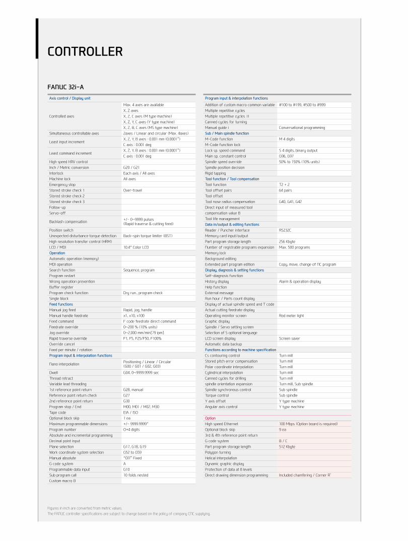
FANUC 32i-AAxis control / Display unit
Controlled axes
Max. 4 axes are availableX, Z axesX, Z, C axes (M type machine)X, Z, Y, C axes (Y type machine)X, Z, B, C axes (MS type machine)
Simultaneous controllable axes 2axes / Linear and circular (Max. 4axes)
Least input incrementX, Z, Y, B axes : 0.001 mm (0.0001”)C axis : 0.001 deg
Least command incrementX, Z, Y, B axes : 0.001 mm (0.0001”)C axis : 0.001 deg
High speed HRV controlInch / Metric conversion G20 / G21Interlock Each axis / All axesMachine lock All axesEmergency stopStored stroke check 1 Over-travelStored stroke check 2Stored stroke check 3Follow-upServo-off
Backlash compensation +/- 0~9999 pulses (Rapid traverse & cutting feed)
Position switchUnexpected disturbance torque detection Back-spin torque limiter (BST)High resolution transfer control (HRM)LCD / MDI 10.4″ Color LCDOperationAutomatic operation (memory)MDI operationSearch function Sequence, programProgram restartWrong operation preventionBuffer registerProgram check function Dry run., program checkSingle blockFeed functionsManual jog feed Rapid, jog, handleManual handle feedrate x1, x10, x100Feed command F code feedrate direct commandFeedrate override 0~200 % (10% units)Jog override 0~2,000 mm/min[79 ipm]Rapid traverse override F1, F5, F25/F50, F100%Override cancelFeed per minute / rotationProgram input & interpolation functions
Nano interpolation Positioning / Linear / Circular (G00 / G01 / G02, G03)
Dwell G04, 0~9999.9999 secThread retractVariable lead threading1st reference point return G28, manualReference point return check G272nd reference point return G30Program stop / End M00, M01 / M02, M30Tape code EIA / ISOOptional block skip 1 eaMaximum programmable dimensions +/- 9999.9999″Program number O+4 digitsAbsolute and incremental programmingDecimal point inputPlane selection G17, G18, G19Work coordinate system selection G52 to G59Manual absolute “ON” FixedG code system AProgrammable data input G10Sub program call 10 folds nestedCustom macro B
Program input & interpolation functions
Addition of custom macro common variable #100 to #199, #500 to #999Multiple repetitive cyclesMultiple repetitive cycles ⅡCanned cycles for turningManual guide i Conversational programmingSub / Main spindle functionM-Code function M 4 digitsM-Code function lockLock sp. speed command S 4 digits, binary outputMain sp. constant control G96, G97Spindle speed override 50% to 150% (10% units)Spindle position decisionRigid tappingTool function / Tool compensationTool function T2 + 2Tool offset pairs 64 pairsTool offsetTool nose radius compensation G40, G41, G42Direct input of measured toolcompensation value BTool life managementData in/output & editing functionsReader / Puncher interface RS232CMemory card input/outputPart program storage length 256 KbyteNumber of registrable programs expansion Max. 500 programsMemory lockBackground editingExtended part program edition Copy, move, change of NC programDisplay, diagnosis & setting functionsSelf-diagnosis functionHistory display Alarm & operation displayHelp functionExternal messageRun hour / Parts count displayDisplay of actual spindle speed and T codeActual cutting feedrate displayOperating monitor screen Rod meter lightGraphic displaySpindle / Servo setting screenSelection of 5 optional languageLCD screen display Screen saverAutomatic data backupFunctions according to machine specificationCs contouring control Turn millStored pitch error compensation Turn millPolar coordinate interpolation Turn millCylindrical interpolation Turn millCanned cycles for drilling Turn millspindle orientation expansion Turn mill, Sub spindleSpindle synchronous control Sub spindleTorque control Sub spindleY axis offset Y type machineAngular axis control Y type machine
OptionHigh speed Ethernet 100 Mbps (Option board is required)Optional block skip 9 ea3rd & 4th reference point returnG code system B / CPart program storage length 512 Kbyte Polygon turningHelical interpolationDynamic graphic displayProtection of data at 8 levelsDirect drawing dimension programming Included chamfering / Corner R`
Figures in inch are converted from metric values.The FANUC controller specifications are subject to change based on the policy of company CNC supplying.
CONTROLLER
HW-MMS
Monitoring
Agent 1
Customer Factory 1
Customer Factory 2
Monitoring
Agent 2
HYUNDAI WIA
Call Center
HYUNDAI WIA
Cloud Server
Customer
Server
Internet
CUSTOMER NETWORK
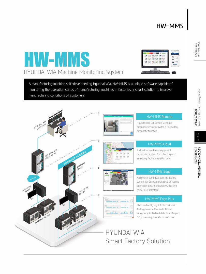
HW-MMS Remote
Hyundai Wia Call Center’s remote diagnosis service provides a HMI/video diagnostic function.
HW-MMS Cloud
A cloud server-based equipment monitoring system for collecting and analyzing facility operation data.
HW-MMS Edge
A client server-based tool monitoring system for collection/analysis of facility operation data. (Compatible with client MES / ERP interface)
HW-MMS Edge Plus
This is a facility big data-based smart factory solution that collects and analyzes spindle/feed data, tool lifespan, NC processing files, etc. in real time
A manufacturing machine self-developed by Hyundai Wia, HW-MMS is a unique software capable of
monitoring the operation status of manufacturing machines in factories, a smart solution to improve
manufacturing conditions of customers
HW-MMSHW-MMSHYUNDAI WIA Machine Monitoring System
HYUNDAI WIAHYUNDAI WIASmart Factory SolutionSmart Factory Solution
14+15
LV14
00/2
000
Ram
Typ
e Ve
rtic
al T
urni
ng C
ente
rH
YUN
DAI W
IAM
ACH
INE
TOOL
EXPE
RIE
NCE
THE
NEW
TEC
HN
OLO
GY
LV2000MM Movie
LV1400 Movie
2021-06 001.003 ENG
With its top-quality HYUNDAI WIA machine tool creates a new and better world.
HEADQUARTERChangwon Technical Center/R&D Center/Factory 153, Jeongdong-ro, Seongsan-gu, Changwon-si, Gyeongsangnam-do, Korea TEL : +82 55 280 9114 FAX : +82 55 282 9114
Overseas Sales Team /R&D Center 37, Cheoldobangmulgwan-ro, Uiwang-si, Gyeonggi-do, Korea TEL : +82 31 8090 2539
OVERSEAS OFFICESHYUNDAI WIA Machine America corp. 450 Commerce Blvd, Carlstadt, NJ 07072, USA TEL : +1-201-987-7298
HYUNDAI WIA Europe GmbH Alexander-Fleming-Ring 57, 65428 Rüsselsheim Germany TEL : +49-0-6142-9256-0
HYUNDAI WIA Machine Tools China 2-3F, Bldg6, No.1535 Hongmei Road, Xuhui District, Shanghai, China TEL : +86-21-6427-9885
India Branch Office #4/169, 1st Floor, LOTTE BLDG, Rajiv Gandhi Salai, (OMR), Kandanchavadi, Chennai - 600096, Tamilnadu, India TEL : +91-76-0490-3348
Vietnam Branch Office Flat number 05, Service and Trade Center of Viet Huong Industrial Zone, Highway 13, Thuan Giao , Thuan An, Binh Duong, Vietnam TEL : +84-3-5399-5099
HYUNDAI WIA MT
www.youtube.com/HYUNDAIWIAMT