Embed Size (px)
Citation preview

¢00825-0100-4420[¤
Quick Installation Guide00825-0100-4420, Rev DAJuly 2009 1420 Wireless Gateway
Step 1: Initial Connection for Configuration
Step 2: Basic Security and Time Configuration
Step 3: Basic Ethernet or Serial Configuration
Step 4: Mount and Connect the Gateway
EC Declaration of Conformity
Start
End
1420 Wireless Gateway
00825-0100-4420_Rev_DA.fm Page 1 Friday, July 17, 2009 10:15 AM
Quick Installation Guide00825-0100-4420, Rev DA
July 20091420 Wireless Gateway
00825-0100-4420_Rev_DA.fm Page 2 Friday, July 17, 2009 10:15 AM
© 2009 Rosemount Inc. All rights reserved. All marks property of owner.
IMPORTANT NOTICE
This installation guide provides basic guidelines for the 1420 Wireless Gateway. It does not provide instructions for detailed configuration, diagnostics, maintenance, service, troubleshooting, or installations. Refer to the 1420 Wireless Gateway reference manual (document number 00809-0100-4420) for more instruction. The manual and this QIG are also available electronically on www.rosemount.com.
WARNING
Explosions could result in death or serious injury:
Installation of this device in an explosive environment must be in accordance with the appropriate local, national, and international standards, codes, and practices. Please review the Hazardous Locations Certifications for any restrictions associated with a safe installation.
Electrical shock can result in death or serious injury• Avoid contact with the leads and terminals. High voltage that may be present on leads
can cause electrical shock.
WARNING
Explosion Hazard
Do not disconnect equipment when a flammable or combustible atmosphere is present.
IMPORTANT NOTICE
The 1420 Wireless Gateway should be installed before installing any other wireless devices. This will result in a simpler and faster network installation.
Emerson Process Management Rosemount Division8200 Market BoulevardChanhassen, MN USA 55317T (US) (800) 999-9307T (Intnl) (952) 906-8888F (952) 949-7001
Rosemount Temperature GmbHFrankenstrasse 2163791 KarlsteinGermanyT 49 (6188) 992 0F 49 (6188) 992 112
Emerson Process ManagementAsia Pacific Private Limited1 Pandan CrescentSingapore 128461T (65) 6777 8211F (65) 6777 0947 / (65) 6777 [email protected]
2

Quick Installation Guide00825-0100-4420, Rev DAJuly 2009 1420 Wireless Gateway
00825-0100-4420_Rev_DA.fm Page 3 Friday, July 17, 2009 10:15 AM
STEP 1: INITIAL CONNECTION FOR CONFIGURATIONTo configure the 1420 Wireless Gateway, a local connection between a PC/laptop and the 1420 Wireless Gateway must be established.
NOTE:If a PC/laptop from another network is used, carefully record the current IP address and other settings so the PC/laptop can be returned to its original network when configuration of the 1420 is finished.
Perform the following steps to establish a local connection with the 1420 Wireless Gateway:
1. On the PC/laptop, install the Java Plug-in found on the CD provided with the 1420. The Plug-in can also be found at http://java.com/
2. Under Network Connections:
a. Select Local Area Connectionb. Right click to select Properties.
3
Quick Installation Guide00825-0100-4420, Rev DA
July 20091420 Wireless Gateway
00825-0100-4420_Rev_DA.fm Page 4 Friday, July 17, 2009 10:15 AM
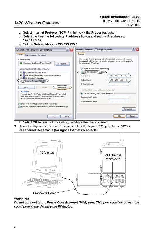
c. Select Internet Protocol (TCP/IP), then click the Properties buttond. Select the Use the following IP address button and set the IP address to
192.168.1.12e. Set the Subnet Mask to 255.255.255.0
f. Select OK for each of the settings windows that have opened.3. Using the supplied crossover Ethernet cable, attach your PC/laptop to the 1420’s
P1 Ethernet Receptacle (far right Ethernet receptacle).
WARNINGDo not connect to the Power Over Ethernet (POE) port. This port supplies power and could potentially damage the PC/laptop.
+ +
+
+
+
-
- -
--A B S S
S S
S
24 V DC24 V DCPower InputPower Input ModbusModbus Not UsedNot Used Not UsedNot Used
Not UsedNot Used Not UsedNot Used
CaseCase
S
POEPOE P2P2 P1P1
P1 Ethernet Receptacle
Crossover Cable
PC/Laptop
4

Quick Installation Guide00825-0100-4420, Rev DAJuly 2009 1420 Wireless Gateway
00825-0100-4420_Rev_DA.fm Page 5 Friday, July 17, 2009 10:15 AM
4. Open a standard web browser (Internet Explorer, Mozilla Firefox or similar).
5. Uncheck proxies (Tools>Internet Options>Connections>LAN Settings)
6. Access the 1420’s default web page at https://192.168.1.10
a. Log on as User: adminb. Password: default
5
Quick Installation Guide00825-0100-4420, Rev DA
July 20091420 Wireless Gateway
00825-0100-4420_Rev_DA.fm Page 6 Friday, July 17, 2009 10:15 AM
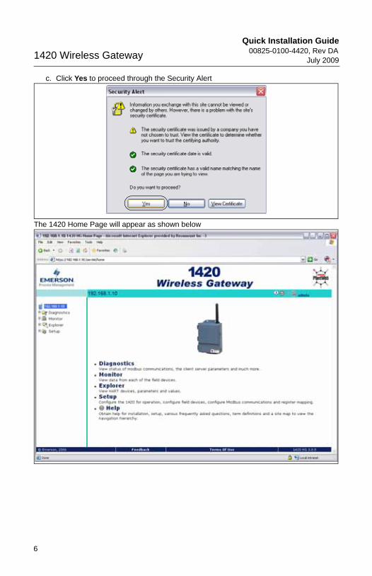
c. Click Yes to proceed through the Security Alert
The 1420 Home Page will appear as shown below
6
Quick Installation Guide00825-0100-4420, Rev DAJuly 2009 1420 Wireless Gateway
00825-0100-4420_Rev_DA.fm Page 7 Friday, July 17, 2009 10:15 AM
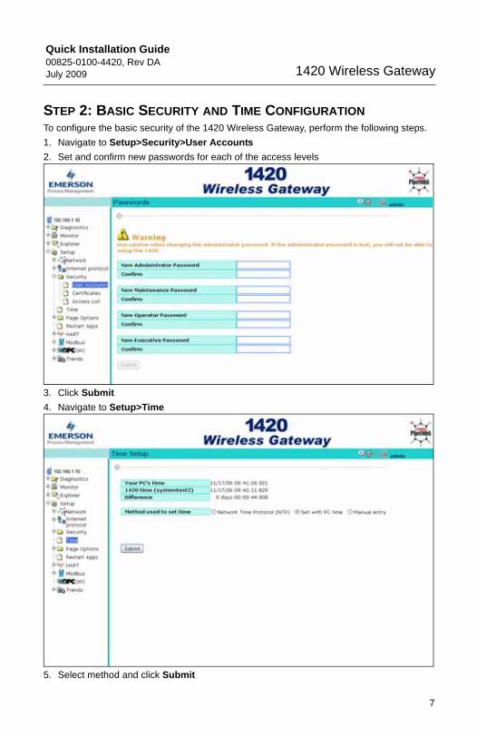
STEP 2: BASIC SECURITY AND TIME CONFIGURATIONTo configure the basic security of the 1420 Wireless Gateway, perform the following steps.
1. Navigate to Setup>Security>User Accounts
2. Set and confirm new passwords for each of the access levels
3. Click Submit
4. Navigate to Setup>Time
5. Select method and click Submit
7
Quick Installation Guide00825-0100-4420, Rev DA
July 20091420 Wireless Gateway
00825-0100-4420_Rev_DA.fm Page 8 Friday, July 17, 2009 10:15 AM
STEP 3: BASIC ETHERNET OR SERIAL CONFIGURATION
To configure the 1420 for an Ethernet Network:Table 3: Ethernet Communication Settings on page 17 is available to assist in recording the necessary information.
1. Determine 1420 Ethernet Port for connecting to Ethernet Network
If using a wired connection, use Port 1 (P1)
IT/Process Control Network Administrator or Technician can provide the following:
a. 1420 fixed IP Address or DHCP Host Nameb. Netmask (Subnet Mask)c. Gateway
BEST PRACTICE:Keep these values in a secure location not accessible by unauthorized personnel.
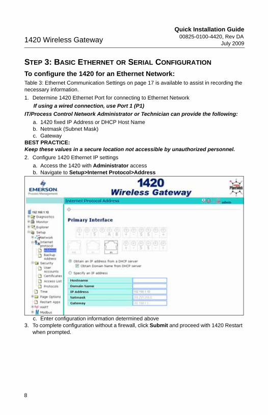
2. Configure 1420 Ethernet IP settings
a. Access the 1420 with Administrator accessb. Navigate to Setup>Internet Protocol>Address
c. Enter configuration information determined above3. To complete configuration without a firewall, click Submit and proceed with 1420 Restart
when prompted.
8
Quick Installation Guide00825-0100-4420, Rev DAJuly 2009 1420 Wireless Gateway
00825-0100-4420_Rev_DA.fm Page 9 Friday, July 17, 2009 10:15 AM
STEP 3 CONTINUED...
To configure the 1420 for a Serial connection: is available to assist in recording the necessary information.
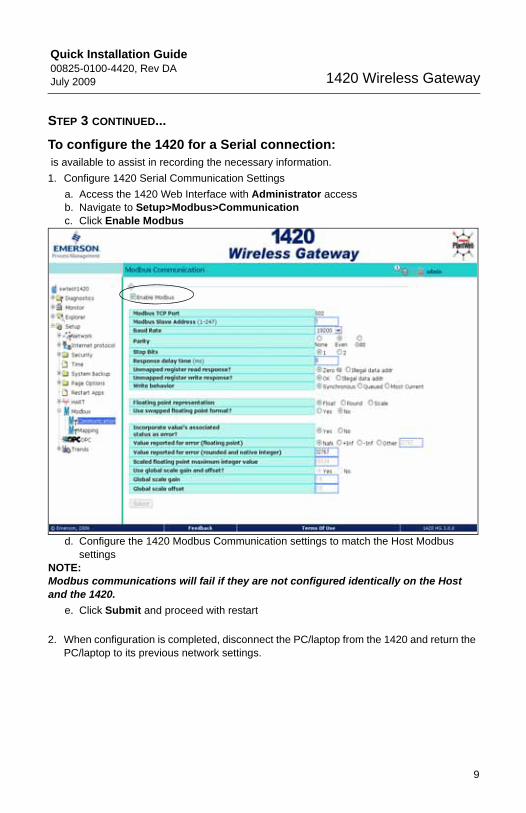
1. Configure 1420 Serial Communication Settings
a. Access the 1420 Web Interface with Administrator accessb. Navigate to Setup>Modbus>Communicationc. Click Enable Modbus
d. Configure the 1420 Modbus Communication settings to match the Host Modbus settings
NOTE:Modbus communications will fail if they are not configured identically on the Host and the 1420.
e. Click Submit and proceed with restart
2. When configuration is completed, disconnect the PC/laptop from the 1420 and return the PC/laptop to its previous network settings.
9
Quick Installation Guide00825-0100-4420, Rev DA1420 Wireless Gateway
00825-0100-4420_Rev_DA.fm Page 10 Friday, July 17, 2009 10:15 AM
July 2009
10
STEP 4: MOUNT AND CONNECT THE GATEWAY
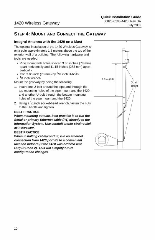
Integral Antenna with the 1420 on a Mast The optimal installation of the 1420 Wireless Gateway is on a pole approximately 1.8 meters above the top of the exterior wall of a building. The following hardware and tools are needed:
• Pipe mount with holes spaced 3.06 inches (78 mm) apart horizontally and 11.15 inches (283 mm) apart vertically.
• Two 3.06 inch (78 mm) by 5/16 inch U-bolts• 1/2 inch wrench
Mount the gateway by doing the following:
1. Insert one U-bolt around the pipe and through the top mounting holes of the pipe mount and the 1420, and another U-bolt through the bottom mounting holes of the pipe mount and the 1420.
2. Using a 1/2 inch socket-head wrench, fasten the nuts to the U-bolts and tighten.
BEST PRACTICEWhen mounting outside, best practice is to run the Serial or primary Ethernet cable (P1) directly to the Information System. Use conduit and/or strain relief as necessary.
BEST PRACTICEWhen installing cable/conduit, run an ethernet connection from 1420 port P2 to a convenient location indoors (if the 1420 was ordered with Output Code 2). This will simplify future configuration changes.
1.8 m (6 ft.)StrainRelief
Quick Installation Guide00825-0100-4420, Rev DAJuly 2009 1420 Wireless Gateway
00825-0100-4420_Rev_DA.fm Page 11 Friday, July 17, 2009 10:15 AM
11
STEP 4 CONTINUED...
Remote Antenna (Optional)The remote antenna options provide flexibility for mounting the Gateway based on wireless connectivity, lightning protection, and current work practices.
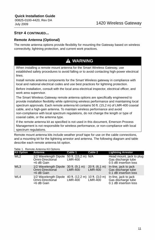
Remote mount antenna kits include weather proof tape for use on the cable connections, and a mounting kit for the lightning arrestor and antenna. The following diagram and table describe each remote antenna kit option.
Table 1. Remote Antenna Kit Options
WARNING
When installing a remote mount antenna for the Smart Wireless Gateway, use established safety procedures to avoid falling or to avoid contacting high-power electrical lines.
Install remote antenna components for the Smart Wireless gateway in compliance with local and national electrical codes and use best practices for lightning protection.
Before installation, consult with the local area electrical inspector, electrical officer, and work area supervisor.
The Smart Wireless Gateway remote antenna options are specifically engineered to provide installation flexibility while optimizing wireless performance and maintaining local spectrum approvals. Each remote antenna kit contains 50 ft. (15,2 m) of LMR-400 coaxial cable, and a high-gain antenna. To maintain wireless performance and avoid non-compliance with local spectrum regulations, do not change the length or type of coaxial cable, or the antenna type.
If the remote antenna kit as specified is not used in this document, Emerson Process Management is not responsible for wireless performance, or non-compliance with local spectrum regulations.
Kit Option Antenna Cable 1 Cable 2 Lightning Arrestor
WL2 1/2 Wavelength Dipole Omni-Directional +6 dB Gain
50 ft. (15,2 m) LMR-400
N/A Head mount, jack to plugGas discharge tube0.5 dB insertion loss
WL3 1/2 Wavelength Dipole Omni-Directional +6 dB Gain
30 ft. (9,1 m) LMR-400
20 ft. (6,1 m) LMR-400
In-line, jack to jackGas discharge tube0.1 dB insertion loss
WL4 1/2 Wavelength Dipole Omni-Directional +6 dB Gain
40 ft. (12,2 m) LMR-400
10 ft. (3,0 m)LMR-400
In-line, jack to jackGas discharge tube0.1 dB insertion loss
Quick Installation Guide00825-0100-4420, Rev DA1420 Wireless Gateway
00825-0100-4420_Rev_DA.fm Page 12 Friday, July 17, 2009 10:15 AM
July 2009
12
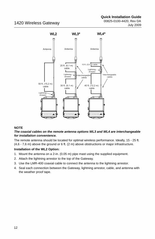
NOTEThe coaxial cables on the remote antenna options WL3 and WL4 are interchangeable for installation convenience.
The remote antenna should be located for optimal wireless performance. Ideally, 15 - 25 ft. (4,6 - 7,6 m) above the ground or 6 ft. (2 m) above obstructions or major infrastructure.
Installation of the WL2 Option:
1. Mount the antenna on a 2-in. (0.05 m) pipe mast using the supplied equipment.
2. Attach the lightning arrestor to the top of the Gateway.
3. Use the LMR-400 coaxial cable to connect the antenna to the lightning arrestor.
4. Seal each connection between the Gateway, lightning arrestor, cable, and antenna with the weather proof tape.
Antenna
50 ft. (15,2 m) cable
Lightning Arrestor
WL2WL2
Antenna
40 ft. (12,2 m) cable
Lightning Arrestor
10 ft. (3,0 m) cable
WL4*WL4*
Interchangeable cables
Antenna
30 ft. (9,1 m) cable
Lightning Arrestor
20 ft. (6,1 m) cable
WL3*WL3*
Interchangeable cables

Quick Installation Guide00825-0100-4420, Rev DAJuly 2009 1420 Wireless Gateway
00825-0100-4420_Rev_DA.fm Page 13 Friday, July 17, 2009 10:15 AM
STEP 4 CONTINUED...
Installation of the WL3/WL4 Option:
1. Mount the antenna on a 2-in. (0.05 m) pipe mast using the supplied equipment.
2. Mount the lightning arrestor using the supplied equipment, minimizing the distance between it and the building egress for optimal lightning protection.
3. Use the LMR-400 coaxial cables to connect the Gateway, lightning arrestor, and antenna.
4. Seal each connection between the Gateway, lightning arrestor, cables, and antenna with the weather proof tape.
Any spare lengths of coaxial cable should be placed in 12-in. (0.3 m) coils.
Ensure that the mounting mast and lightning arrestor are grounded in accordance with local/national electrical codes.
Example of Mounting a Remote Antenna
Ground to Lightning Arrestor
Control/Equipment Room
Remote Antenna outside of enclosure
Ground to Gateway
Lightning Arrestor
Antenna mounted6 ft. (2 m) above obstruction or majorinfastructure
0 ft. (0 m)
6 ft. (2 m)
Gateway Insidethe Building
CableCable
CableBuilding Egress
13
Quick Installation Guide00825-0100-4420, Rev DA
July 20091420 Wireless Gateway
00825-0100-4420_Rev_DA.fm Page 14 Friday, July 17, 2009 10:15 AM
14
STEP 4 CONTINUED...
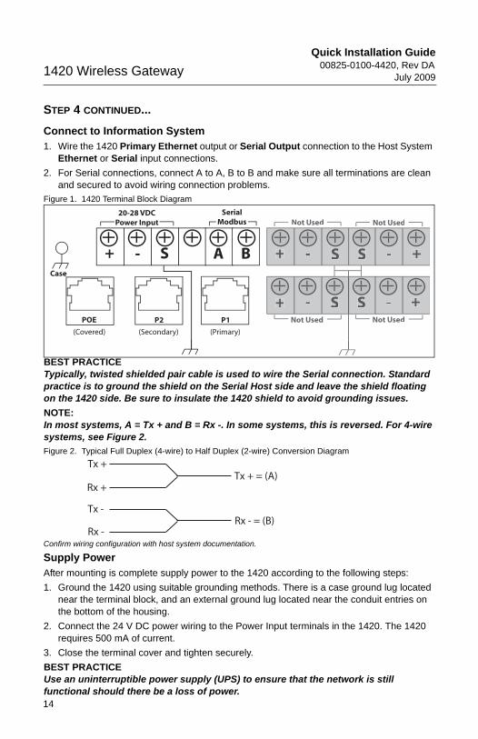
Connect to Information System1. Wire the 1420 Primary Ethernet output or Serial Output connection to the Host System
Ethernet or Serial input connections.
2. For Serial connections, connect A to A, B to B and make sure all terminations are clean and secured to avoid wiring connection problems.
Figure 1. 1420 Terminal Block Diagram
BEST PRACTICETypically, twisted shielded pair cable is used to wire the Serial connection. Standard practice is to ground the shield on the Serial Host side and leave the shield floating on the 1420 side. Be sure to insulate the 1420 shield to avoid grounding issues.
NOTE:In most systems, A = Tx + and B = Rx -. In some systems, this is reversed. For 4-wire systems, see Figure 2.
Figure 2. Typical Full Duplex (4-wire) to Half Duplex (2-wire) Conversion Diagram
Confirm wiring configuration with host system documentation.
Supply PowerAfter mounting is complete supply power to the 1420 according to the following steps:
1. Ground the 1420 using suitable grounding methods. There is a case ground lug located near the terminal block, and an external ground lug located near the conduit entries on the bottom of the housing.
2. Connect the 24 V DC power wiring to the Power Input terminals in the 1420. The 1420 requires 500 mA of current.
3. Close the terminal cover and tighten securely.
BEST PRACTICEUse an uninterruptible power supply (UPS) to ensure that the network is still functional should there be a loss of power.
+ +
+
+
+
-
- -
--A B S S
S S
20-28 VDCPower Input
SerialModbus Not Used Not Used
Not Used Not Used
Case
(Covered)
S
POE P2 P1
(Secondary) (Primary)
Tx +Tx + = (A)
Rx +
Tx -
Rx -Rx - = (B)
Quick Installation Guide00825-0100-4420, Rev DAJuly 2009 1420 Wireless Gateway
00825-0100-4420_Rev_DA.fm Page 15 Friday, July 17, 2009 10:15 AM
15
PRODUCT CERTIFICATIONS
Approved Manufacturing LocationsRosemount Inc. – Chanhassen, Minnesota, USA
Telecommunication ComplianceAll wireless devices require certification to ensure that they adhere to regulations regarding the use of the RF spectrum. Nearly every country requires this type of product certification. Emerson is working with governmental agencies around the world to supply fully compliant products and remove the risk of violating country directives or laws governing wireless device usage.
FCC and ICThis device complies with Part 15 of the FCC Rules. Operation is subject to the following conditions: This device may not cause harmful interference. This device must accept any interference received, including interference that may cause undesired operation. This device must be installed to ensure a minimum antenna separation distance of 20 cm from all persons.
Ordinary Location Certification for FMAs standard, the Gateway has been examined and tested to determine that the design meets basic electrical, mechanical, and fire protection requirements by FM, a nationally recognized testing laboratory (NRTL) as accredited by the Federal Occupational Safety and Health Administration (OSHA).
North American Certifications
N5 FM Division 2, Non-IncendiveCertificate Number: 3028321Nonincendive for Class I, Division 2, Groups A, B, C, and D.Dust Ignition-proof for Class II, III, Division 1, Groups E, F, and G; Indoors/outdoor locations;NEMA Type 4XTemperature Code: T4 (-40 °C < Ta < 60 °C)
Canadian Standards Association (CSA)
N6 CSA Division 2, Non-IncendiveCertificate Number: 1849337Suitable for Class I, Division 2, Groups A, B, C, and D.Dust Ignition-proof for Class II, Groups E, F, and G; Suitable for Class III Hazardous Locations.;Install per Rosemount drawing 01420-1011.Temperature Code: T4 (-40 °C < Ta < 60 °C)CSA Enclosure Type 4X
European Union Directive InformationThe EC declaration of conformity for all applicable European directives for this product can be found on the Rosemount website at www.rosemount.com. A hard copy may be obtained by contacting your local sales representative.
(continued on page 16)
Quick Installation Guide00825-0100-4420, Rev DA
July 20091420 Wireless Gateway
00825-0100-4420_Rev_DA.fm Page 16 Friday, July 17, 2009 10:15 AM
ATEX Directive (94/9/EC)
Emerson Process Management complies with the ATEX Directive.
Electro Magnetic Compatibility (EMC) (2004/108/EC)
Emerson Process Management complies with the EMC Directive.
Radio and Telecommunications Terminal Equipment Directive (R&TTE)(1999/5/EC)
Emerson Process Management complies with the R&TTE Directive
European Certification
N1 ATEX Type n Certificate Number: Baseefa 07ATEX0056XATEX Marking: Ex II 3 GEx nA Nl IIC T4 (-40 °C < Ta < 60 °C)Special Conditions for Safe Use (X)
The surface resistivity of the antenna is greater than one gigaohm. To avoid electrostatic charge build-up, it must not be rubbed or cleaned with solvents or a dry cloth.
The Apparatus is not capable of withstanding the 500V insulation test required by Clause 9.4 of EN 60079-15: 2005. This must be taken into account when installing the apparatus.
ND ATEX DustCertificate Number: Baseefa 07ATEX0057EX tD A 22 IP66 T135 (-40 °C < Ta < 60 °C)Ex nA nL IIC T4 T4 (-40 °C < Ta < 60 °C) II 3DVmax = 28V
N7 IECEx Type n Certificate Number: IECEx BAS 07.0012XEx nC IIC T4 (-40 °C =< Ta <=60 °C)Rated Voltage: 28VSpecial conditions for safe use (X)
The surface resistivity of the antenna is greater than one gigaohm. To avoid electrostatic charge build-up, it must not be rubbed or cleaned with solvents or a dry cloth.
The Apparatus is not capable of withstanding the 500V insulation test required by Clause 9.4 of EN 60079-15: 2005. This must be taken into account when installing the apparatus.
NF IECEx DustCertification Number: IECEx BAS 07.0013Ex tD A22 IP66 T135 (-40 °C < Ta < 60 °C)Vmax = 28V
Combinations of Certifcations
KD Combination of N5, N6, and N1.
16
Quick Installation Guide00825-0100-4420, Rev DAJuly 2009 1420 Wireless Gateway
00825-0100-4420_Rev_DA.fm Page 17 Friday, July 17, 2009 10:15 AM
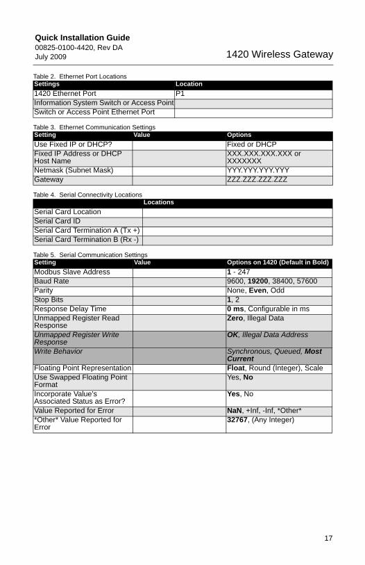
Table 2. Ethernet Port Locations
Table 3. Ethernet Communication Settings
Table 4. Serial Connectivity Locations
Table 5. Serial Communication Settings
Settings Location
1420 Ethernet Port P1Information System Switch or Access PointSwitch or Access Point Ethernet Port
Setting Value Options
Use Fixed IP or DHCP? Fixed or DHCPFixed IP Address or DHCP Host Name
XXX.XXX.XXX.XXX or XXXXXXX
Netmask (Subnet Mask) YYY.YYY.YYY.YYYGateway ZZZ.ZZZ.ZZZ.ZZZ
Locations
Serial Card LocationSerial Card IDSerial Card Termination A (Tx +)Serial Card Termination B (Rx -)
Setting Value Options on 1420 (Default in Bold)
Modbus Slave Address 1 - 247Baud Rate 9600, 19200, 38400, 57600Parity None, Even, OddStop Bits 1, 2Response Delay Time 0 ms, Configurable in msUnmapped Register Read Response
Zero, Illegal Data
Unmapped Register Write Response
OK, Illegal Data Address
Write Behavior Synchronous, Queued, Most Current
Floating Point Representation Float, Round (Integer), ScaleUse Swapped Floating Point Format
Yes, No
Incorporate Value’s Associated Status as Error?
Yes, No
Value Reported for Error NaN, +Inf, -Inf, *Other**Other* Value Reported for Error
32767, (Any Integer)
17

Quick Installation Guide00825-0100-4420, Rev DA
July 20091420 Wireless Gateway
00825-0100-4420_Rev_DA.fm Page 18 Friday, July 17, 2009 10:15 AM
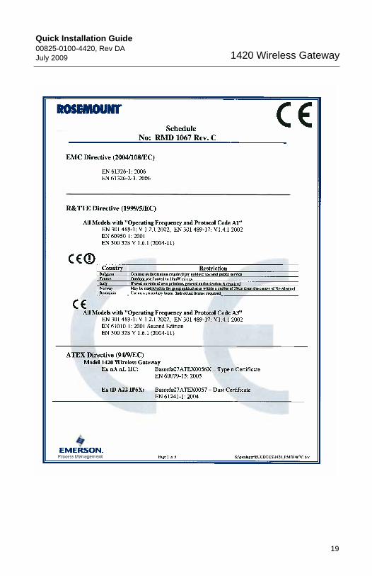
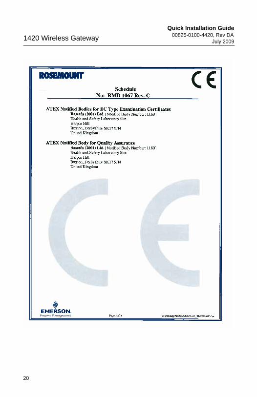
Figure 3. EC Declaration of Conformity for 1420 Wireless Gateway
18
Quick Installation Guide00825-0100-4420, Rev DAJuly 2009 1420 Wireless Gateway
00825-0100-4420_Rev_DA.fm Page 19 Friday, July 17, 2009 10:15 AM
19
Quick Installation Guide00825-0100-4420, Rev DA
July 20091420 Wireless Gateway
00825-0100-4420_Rev_DA.fm Page 20 Friday, July 17, 2009 10:15 AM
20