Embed Size (px)
Citation preview

76 •
C h a p t e r 20 Magnetic Properties
Photomicrographs of an iron single
crystal, showing magnetic domains and
their change in shape as a magnetic field
(H) is applied. The magnetization direc-
tion of each domain is indicated by an
arrow. Those domains that are favorably
oriented with the applied field grow at
the expense of the unfavorably oriented
domains. (Photomicrographs courtesy of
General Electric Research Laboratory.)
An understanding of the mechanism that explains thepermanent magnetic behavior of some materials mayallow us to alter and in some cases tailor the magnetic
properties. For example, in Design Example 20.1 wenote how the behavior of a ceramic magnetic materialmay be enhanced by changing its composition.
WHY STUDY the Magnetic Properties of Materials?
1496T_c20_76-113 10/31/05 16:31 Page 76 FIRST PAGES
L e a r n i n g O b j e c t i v e sAfter careful study of this chapter you should be able to do the following:
1. Determine the magnetization of some materialgiven its magnetic susceptibility and the appliedmagnetic field strength.
2. From an electronic perspective note and brieflyexplain the two sources of magnetic moments inmaterials.
3. Briefly explain the nature and source of (a) diamagnetism, (b) paramagnetism, and(c) ferromagnetism.
4. In terms of crystal structure, explain the sourceof ferrimagnetism for cubic ferrites.
5. (a) Describe magnetic hysteresis; (b) explainwhy ferromagnetic and ferrimagnetic materialsexperience magnetic hysteresis; and (c) explainwhy these materials may become permanentmagnets.
6. Note the distinctive magnetic characteristics forboth soft and hard magnetic materials.
7. Describe the phenomenon of superconductivity.
20.1 INTRODUCTIONMagnetism, the phenomenon by which materials assert an attractive or repulsiveforce or influence on other materials, has been known for thousands of years. How-ever, the underlying principles and mechanisms that explain the magnetic phe-nomenon are complex and subtle, and their understanding has eluded scientists untilrelatively recent times. Many of our modern technological devices rely on magnet-ism and magnetic materials; these include electrical power generators and trans-formers, electric motors, radio, television, telephones, computers, and componentsof sound and video reproduction systems.
Iron, some steels, and the naturally occurring mineral lodestone are well-knownexamples of materials that exhibit magnetic properties. Not so familiar, however, isthe fact that all substances are influenced to one degree or another by the presenceof a magnetic field.This chapter provides a brief description of the origin of magneticfields and discusses the various magnetic field vectors and magnetic parameters; thephenomena of diamagnetism, paramagnetism, ferromagnetism, and ferrimagnetism;some of the different magnetic materials; and the phenomenon of superconductivity.
20.2 BASIC CONCEPTSMagnetic DipolesMagnetic forces are generated by moving electrically charged particles; these mag-netic forces are in addition to any electrostatic forces that may prevail. Many timesit is convenient to think of magnetic forces in terms of fields. Imaginary lines offorce may be drawn to indicate the direction of the force at positions in the vicin-ity of the field source. The magnetic field distributions as indicated by lines of forceare shown for a current loop and also a bar magnet in Figure 20.1.
Magnetic dipoles are found to exist in magnetic materials, which, in some re-spects, are analogous to electric dipoles (Section 18.19). Magnetic dipoles may bethought of as small bar magnets composed of north and south poles instead of pos-itive and negative electric charges. In the present discussion, magnetic dipolemoments are represented by arrows, as shown in Figure 20.2. Magnetic dipoles areinfluenced by magnetic fields in a manner similar to the way in which electric dipolesare affected by electric fields (Figure 18.30). Within a magnetic field, the force ofthe field itself exerts a torque that tends to orient the dipoles with the field. A fa-miliar example is the way in which a magnetic compass needle lines up with theearth’s magnetic field.
1496T_c20_76-113 10/31/05 16:31 Page 77 FIRST PAGES
Magnetic Field VectorsBefore discussing the origin of magnetic moments in solid materials, we describemagnetic behavior in terms of several field vectors. The externally applied mag-netic field, sometimes called the magnetic field strength, is designated by H. Ifthe magnetic field is generated by means of a cylindrical coil (or solenoid) consistingof N closely spaced turns, having a length l, and carrying a current of magnitudeI, then
(20.1)
A schematic diagram of such an arrangement is shown in Figure 20.3a. The magneticfield that is generated by the current loop and the bar magnet in Figure 20.1 is anH field. The units of H are ampere-turns per meter, or just amperes per meter.
The magnetic induction, or magnetic flux density, denoted by B, represents themagnitude of the internal field strength within a substance that is subjected to anH field. The units for B are teslas [or webers per square meter Both Band H are field vectors, being characterized not only by magnitude, but also bydirection in space.
(Wb/m2)].
H �NIl
78 • Chapter 20 / Magnetic Properties
N
S
Figure 20.1 Magnetic field lines of force around a currentloop and a bar magnet.
magnetic fieldstrength
Magnetic fieldstrength within acoil—dependence onnumber of turns,applied current, andcoil length
magnetic induction,magnetic fluxdensity
N
S
Figure 20.2 The magnetic moment as designated by an arrow.
1496T_c20_76-113 10/31/05 16:31 Page 78 FIRST PAGES

The magnetic field strength and flux density are related according to
(20.2)
The parameter is called the permeability, which is a property of the specificmedium through which the H field passes and in which B is measured, as illustratedin Figure 20.3b. The permeability has dimensions of webers per ampere-meter(Wb/A-m) or henries per meter (H/m).
In a vacuum,
(20.3)
where is the permeability of a vacuum, a universal constant, which has a valueof The parameter represents the flux densitywithin a vacuum as demonstrated in Figure 20.3a.
Several parameters may be used to describe the magnetic properties of solids.One of these is the ratio of the permeability in a material to the permeability in avacuum, or
(20.4)
where is called the relative permeability, which is unitless. The permeability orrelative permeability of a material is a measure of the degree to which the materialcan be magnetized, or the ease with which a B field can be induced in the presenceof an external H field.
Another field quantity, M, called the magnetization of the solid, is defined bythe expression
(20.5)
In the presence of an H field, the magnetic moments within a material tend to be-come aligned with the field and to reinforce it by virtue of their magnetic fields;the term in Equation 20.5 is a measure of this contribution.m0M
B � m0H � m0M
mr
mr �m
m0
B0(1.257 � 10�6) H/m.4p � 10�7m0
B0 � m0H
m
B � mH
20.2 Basic Concepts • 79
I
I
N turns
H
B0 = �0H
(a)
I
I
B = �H
(b)
Hl
Figure 20.3 (a) The magnetic field H as generated by a cylindrical coil is dependent onthe current I, the number of turns N, and the coil length l, according to Equation 20.1. Themagnetic flux density in the presence of a vacuum is equal to where is thepermeability of a vacuum, H/m. (b) The magnetic flux density B within a solidmaterial is equal to where is the permeability of the solid material. (Adapted fromA. G. Guy, Essentials of Materials Science, McGraw-Hill Book Company, New York, 1976.)
mmH,4p � 10�7
m0m0H,B0
Magnetic fluxdensity in amaterial—dependence onpermeability andmagnetic fieldstrength
permeability
Magnetic fluxdensity in a vacuum
Definition of relativepermeability
magnetization
Magnetic fluxdensity—as afunction of magneticfield strength andmagnetization of amaterial
1496T_c20_76-113 10/31/05 16:31 Page 79 FIRST PAGES
The magnitude of M is proportional to the applied field as follows:
(20.6)
and is called the magnetic susceptibility, which is unitless.1 The magnetic sus-ceptibility and the relative permeability are related as follows:
(20.7)
There is a dielectric analogue for each of the foregoing magnetic field param-eters. The B and H fields are, respectively, analogous to the dielectric displacementD and the electric field whereas the permeability parallels the permittivity (cf. Equations 20.2 and 18.30). Furthermore, the magnetization M and polarizationP are correlates (Equations 20.5 and 18.31).
Magnetic units may be a source of confusion because there are really twosystems in common use. The ones used thus far are SI [rationalized MKS (meter-kilogram-second)]; the others come from the (centimeter-gram-second-electromagnetic unit) system. The units for both systems as well as the appropriateconversion factors are contained in Table 20.1.
Origins of Magnetic MomentsThe macroscopic magnetic properties of materials are a consequence of magneticmoments associated with individual electrons. Some of these concepts are relativelycomplex and involve some quantum-mechanical principles beyond the scope of thisdiscussion; consequently, simplifications have been made and some of the detailsomitted. Each electron in an atom has magnetic moments that originate from twosources. One is related to its orbital motion around the nucleus; being a moving
cgs–emu
�me,
xm � mr � 1
xm
M � xmH
80 • Chapter 20 / Magnetic Properties
Table 20.1 Magnetic Units and Conversion Factors for the SI and cgs–emu Systems
SI Units cgs–emuQuantity Symbol Derived Primary Unit Conversion
Magnetic induction B tesla (Wb/m2)a kg/s-C gauss 1 Wb/m2 � 104 gauss(flux density)
Magnetic field H amp-turn/m C/m-s oersted 1 amp-turn/m � 4� �strength 10�3 oersted
Magnetization M (SI) amp-turn/m C/m-s maxwell/cm2 1 amp-turn/m � 10�3
I (cgs–emu) maxwell/cm2
Permeability of a �0 henry/mb kg-m/C2 Unitless (emu) 4� � 10�7 henry/m � vaccum 1 emu
Relative permeability �r (SI) Unitless Unitless Unitless �r � ���� (cgs–emu)
Susceptibility �m (SI) Unitless Unitless Unitless �m � 4���m��m (cgs–emu)
a Units of the weber (Wb) are volt-seconds.b Units of the henry are webers per ampere.
magneticsusceptibility
Magnetizationof a material—dependence onsusceptibility andmagnetic fieldstrength
Relationshipbetween magneticsusceptibility andrelative permeability
1 This is taken to be the volume susceptibility in SI units, which, when multiplied by H,yields the magnetization per unit volume (cubic meter) of material. Other susceptibilitiesare also possible; see Problem 20.3.
xm
1496T_c20_76-113 10/31/05 16:31 Page 80 FIRST PAGES
charge, an electron may be considered to be a small current loop, generating a verysmall magnetic field, and having a magnetic moment along its axis of rotation, asschematically illustrated in Figure 20.4a.
Each electron may also be thought of as spinning around an axis; the othermagnetic moment originates from this electron spin, which is directed along thespin axis as shown in Figure 20.4b. Spin magnetic moments may be only in an “up”direction or in an antiparallel “down” direction. Thus each electron in an atom maybe thought of as being a small magnet having permanent orbital and spin magneticmoments.
The most fundamental magnetic moment is the Bohr magneton which isof magnitude For each electron in an atom the spin magneticmoment is (plus for spin up, minus for spin down). Furthermore, the orbitalmagnetic moment contribution is equal to being the magnetic quantumnumber of the electron, as mentioned in Section 2.3.
In each individual atom, orbital moments of some electron pairs cancel eachother; this also holds for the spin moments. For example, the spin moment of anelectron with spin up will cancel that of one with spin down. The net magneticmoment, then, for an atom is just the sum of the magnetic moments of each of theconstituent electrons, including both orbital and spin contributions, and taking intoaccount moment cancellation. For an atom having completely filled electron shellsor subshells, when all electrons are considered, there is total cancellation of bothorbital and spin moments. Thus materials composed of atoms having completelyfilled electron shells are not capable of being permanently magnetized. This cate-gory includes the inert gases (He, Ne, Ar, etc.) as well as some ionic materials. Thetypes of magnetism include diamagnetism, paramagnetism, and ferromagnetism; inaddition, antiferromagnetism and ferrimagnetism are considered to be subclassesof ferromagnetism.All materials exhibit at least one of these types, and the behaviordepends on the response of electron and atomic magnetic dipoles to the applicationof an externally applied magnetic field.
20.3 DIAMAGNETISM AND PARAMAGNETISMDiamagnetism is a very weak form of magnetism that is nonpermanent and persistsonly while an external field is being applied. It is induced by a change in the orbitalmotion of electrons due to an applied magnetic field. The magnitude of the inducedmagnetic moment is extremely small, and in a direction opposite to that of the ap-plied field. Thus, the relative permeability is less than unity (however, only veryslightly), and the magnetic susceptibility is negative; that is, the magnitude of the Bfield within a diamagnetic solid is less than that in a vacuum. The volume suscep-tibility for diamagnetic solid materials is on the order of When placedbetween the poles of a strong electromagnet, diamagnetic materials are attractedtoward regions where the field is weak.
�10�5.xm
mr
mlmB, ml
�mB
9.27 � 10�24 A-m2.mB,
20.3 Diamagnetism and Paramagnetism • 81
Magneticmoment
Atomicnucleus
Electron
+
(a)
Magneticmoment
Directionof spin
Electron
(b)
Figure 20.4 Demonstration of themagnetic moment associated with(a) an orbiting electron and (b) aspinning electron.
Bohr magneton
diamagnetism
1496T_c20_76-113 10/31/05 16:31 Page 81 FIRST PAGES
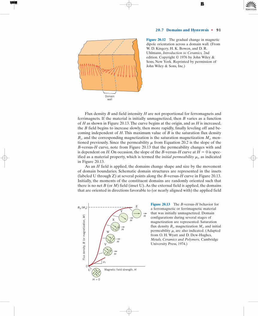
Figure 20.5a illustrates schematically the atomic magnetic dipole configura-tions for a diamagnetic material with and without an external field; here, thearrows represent atomic dipole moments, whereas for the preceding discussion,arrows denoted only electron moments. The dependence of B on the external fieldH for a material that exhibits diamagnetic behavior is presented in Figure 20.6.Table 20.2 gives the susceptibilities of several diamagnetic materials. Diamagnet-ism is found in all materials; but because it is so weak, it can be observed onlywhen other types of magnetism are totally absent. This form of magnetism is ofno practical importance.
For some solid materials, each atom possesses a permanent dipole moment byvirtue of incomplete cancellation of electron spin and/or orbital magnetic moments.In the absence of an external magnetic field, the orientations of these atomic mag-netic moments are random, such that a piece of material possesses no net macro-scopic magnetization. These atomic dipoles are free to rotate, and paramagnetismresults when they preferentially align, by rotation, with an external field as shownin Figure 20.5b. These magnetic dipoles are acted on individually with no mutual
82 • Chapter 20 / Magnetic Properties
H = 0H
(a)
H = 0H
(b)
Figure 20.5 (a) The atomic dipoleconfiguration for a diamagnetic materialwith and without a magnetic field. In theabsence of an external field, no dipoles exist;in the presence of a field, dipoles areinduced that are aligned opposite to the fielddirection. (b) Atomic dipole configurationwith and without an external magnetic fieldfor a paramagnetic material.
Flux
den
sity
, B
Paramagnetic
Vacuum
Diamagnetic
00
Magnetic field strength, H
Figure 20.6 Schematicrepresentation of the flux densityB versus the magnetic fieldstrength H for diamagnetic andparamagnetic materials.
paramagnetism
1496T_c20_76-113 10/31/05 16:31 Page 82 FIRST PAGES

interaction between adjacent dipoles. Inasmuch as the dipoles align with the exter-nal field, they enhance it, giving rise to a relative permeability that is greater thanunity, and to a relatively small but positive magnetic susceptibility. Susceptibilitiesfor paramagnetic materials range from about to (Table 20.2). A schematicB-versus-H curve for a paramagnetic material is also shown in Figure 20.6.
Both diamagnetic and paramagnetic materials are considered to be nonmag-netic because they exhibit magnetization only when in the presence of an externalfield. Also, for both, the flux density B within them is almost the same as it wouldbe in a vacuum.
20.4 FERROMAGNETISMCertain metallic materials possess a permanent magnetic moment in the absenceof an external field, and manifest very large and permanent magnetizations. Theseare the characteristics of ferromagnetism, and they are displayed by the transi-tion metals iron (as BCC ferrite), cobalt, nickel, and some of the rare earth met-als such as gadolinium (Gd). Magnetic susceptibilities as high as are possiblefor ferromagnetic materials. Consequently, and from Equation 20.5 wewrite
(20.8)
Permanent magnetic moments in ferromagnetic materials result from atomicmagnetic moments due to electron spin—uncancelled electron spins as a consequenceof the electron structure. There is also an orbital magnetic moment contribution thatis small in comparison to the spin moment. Furthermore, in a ferromagnetic mate-rial, coupling interactions cause net spin magnetic moments of adjacent atoms toalign with one another, even in the absence of an external field. This is schemati-cally illustrated in Figure 20.7. The origin of these coupling forces is not completelyunderstood, but it is thought to arise from the electronic structure of the metal. Thismutual spin alignment exists over relatively large volume regions of the crystalcalled domains (see Section 20.7).
The maximum possible magnetization, or saturation magnetization of aferromagnetic material represents the magnetization that results when all themagnetic dipoles in a solid piece are mutually aligned with the external field; there
Ms,
B � m0 M
H V M,106
a
10�210�5
mr
20.4 Ferromagnetism • 83
Table 20.2 Room-Temperature Magnetic Susceptibilities for Diamagnetic andParamagnetic Materials
Diamagnetics Paramagnetics
Susceptibility Susceptibility�m (volume) �m (volume)
Material (SI units) Material (SI units)
Aluminum oxide �1.81 � 10�5 Aluminum 2.07 � 10�5
Copper �0.96 � 10�5 Chromium 3.13 � 10�4
Gold �3.44 � 10�5 Chromium chloride 1.51 � 10�3
Mercury �2.85 � 10�5 Manganese sulfate 3.70 � 10�3
Silicon �0.41 � 10�5 Molybdenum 1.19 � 10�4
Silver �2.38 � 10�5 Sodium 8.48 � 10�6
Sodium chloride �1.41 � 10�5 Titanium 1.81 � 10�4
Zinc �1.56 � 10�5 Zirconium 1.09 � 10�4
ferromagnetism
For a ferromagneticmaterial, relationshipbetween magneticflux density andmagnetization
domain
saturationmagnetization
1496T_c20_76-113 10/31/05 16:31 Page 83 FIRST PAGES
84 • Chapter 20 / Magnetic Properties
H = 0 Figure 20.7 Schematic illustration of the mutual alignment of atomicdipoles for a ferromagnetic material, which will exist even in theabsence of an external magnetic field.
is also a corresponding saturation flux density The saturation magnetization isequal to the product of the net magnetic moment for each atom and the numberof atoms present. For each of iron, cobalt, and nickel, the net magnetic momentsper atom are 2.22, 1.72, and 0.60 Bohr magnetons, respectively.
EXAMPLE PROBLEM 20.1
Saturation Magnetization and Flux Density Computationsfor Nickel
Calculate (a) the saturation magnetization and (b) the saturation flux densityfor nickel, which has a density of 8.90 g/cm3.
Solution
(a) The saturation magnetization is just the product of the number of Bohrmagnetons per atom (0.60 as given above), the magnitude of the Bohr magne-ton and the number N of atoms per cubic meter, or
(20.9)
Now, the number of atoms per cubic meter is related to the density theatomic weight and Avogadro’s number as follows:
(20.10)
Finally,
(b) From Equation 20.8, the saturation flux density is just
� 0.64 tesla
� a4p � 10�7 Hm
b a5.1 � 105 Am
b Bs � m0Ms
� 5.1 � 105 A/m
Ms � a0.60 Bohr magneton
atomb a9.27 � 10�24 A-m2
Bohr magnetonb a9.13 � 1028 atoms
m3 b
� 9.13 � 1028 atoms/m3
�18.90 � 106 g/m32 16.023 � 1023 atoms/mol2
58.71 g/mol
N �rNA
ANi
NA,ANi,r,
Ms � 0.60mBN
mB,
Bs.
Saturationmagnetizationfor nickel
For nickel,computation of thenumber of atoms perunit volume
1496T_c20_76-113 10/31/05 16:31 Page 84 FIRST PAGES
20.5 ANTIFERROMAGNETISM ANDFERRIMAGNETISM
AntiferromagnetismThis phenomenon of magnetic moment coupling between adjacent atoms or ionsoccurs in materials other than those that are ferromagnetic. In one such group, thiscoupling results in an antiparallel alignment; the alignment of the spin moments ofneighboring atoms or ions in exactly opposite directions is termed antiferromag-netism. Manganese oxide (MnO) is one material that displays this behavior. Man-ganese oxide is a ceramic material that is ionic in character, having both and
ions. No net magnetic moment is associated with the ions, since there isa total cancellation of both spin and orbital moments. However, the ions pos-sess a net magnetic moment that is predominantly of spin origin. These ionsare arrayed in the crystal structure such that the moments of adjacent ions are an-tiparallel. This arrangement is represented schematically in Figure 20.8. Obviously,the opposing magnetic moments cancel one another, and, as a consequence, thesolid as a whole possesses no net magnetic moment.
FerrimagnetismSome ceramics also exhibit a permanent magnetization, termed ferrimagnetism. Themacroscopic magnetic characteristics of ferromagnets and ferrimagnets are similar;the distinction lies in the source of the net magnetic moments. The principles of fer-rimagnetism are illustrated with the cubic ferrites.2 These ionic materials may berepresented by the chemical formula in which M represents any one ofseveral metallic elements. The prototype ferrite is the mineral magnetite,sometimes called lodestone.
The formula for may be written as in which theFe ions exist in both �2 and �3 valence states in the ratio of 1:2. A net spin mag-netic moment exists for each and ion, which corresponds to 4 and 5 Bohrmagnetons, respectively, for the two ion types. Furthermore, the ions are mag-netically neutral. There are antiparallel spin-coupling interactions between the Feions, similar in character to antiferromagnetism. However, the net ferrimagneticmoment arises from the incomplete cancellation of spin moments.
Cubic ferrites have the inverse spinel crystal structure, which is cubic in sym-metry, and similar to the spinel structure (Section 12.2). The inverse spinel crystal
O2�Fe3�Fe2�
Fe2�O2�–(Fe3�)2(O2�)3Fe3O4
Fe3O4,MFe2O4,
Mn2�Mn2�
O2�O2�Mn2�
20.5 Antiferromagnetism and Ferrimagnetism • 85
02–Mn2+
Figure 20.8 Schematic representation of antiparallelalignment of spin magnetic moments for antiferromagneticmanganese oxide.
antiferromagnetism
ferrimagnetism
2 Ferrite in the magnetic sense should not be confused with the ferrite -iron discussed inSection 9.18; in the remainder of this chapter, the term ferrite implies the magnetic ceramic.
a
ferrite
1496T_c20_76-113 10/31/05 16:31 Page 85 FIRST PAGES
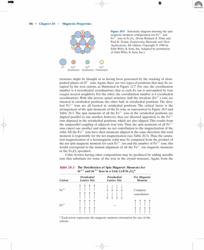
structure might be thought of as having been generated by the stacking of close-packed planes of ions. Again, there are two types of positions that may be oc-cupied by the iron cations, as illustrated in Figure 12.7. For one, the coordinationnumber is 4 (tetrahedral coordination); that is, each Fe ion is surrounded by fouroxygen nearest neighbors. For the other, the coordination number is 6 (octahedralcoordination). With this inverse spinel structure, half the trivalent ions aresituated in octahedral positions, the other half, in tetrahedral positions. The diva-lent ions are all located in octahedral positions. The critical factor is thearrangement of the spin moments of the Fe ions, as represented in Figure 20.9 andTable 20.3. The spin moments of all the ions in the octahedral positions arealigned parallel to one another; however, they are directed oppositely to the ions disposed in the tetrahedral positions, which are also aligned. This results fromthe antiparallel coupling of adjacent iron ions. Thus, the spin moments of all ions cancel one another and make no net contribution to the magnetization of thesolid. All the ions have their moments aligned in the same direction; this totalmoment is responsible for the net magnetization (see Table 20.3). Thus, the satura-tion magnetization of a ferrimagnetic solid may be computed from the product ofthe net spin magnetic moment for each ion and the number of ions; thiswould correspond to the mutual alignment of all the ion magnetic momentsin the specimen.
Cubic ferrites having other compositions may be produced by adding metallicions that substitute for some of the iron in the crystal structure. Again, from the
Fe3O4
Fe2�Fe2�Fe2�
Fe2�
Fe3�
Fe3�Fe3�
Fe2�
(Fe3�)
O2�
86 • Chapter 20 / Magnetic Properties
02– Fe2+
(Octahedral)Fe3+
(Octahedral)Fe3+
(Tetrahedral)
Figure 20.9 Schematic diagram showing the spinmagnetic moment configuration for and
ions in (From Richard A. Flinn andPaul K. Trojan, Engineering Materials and TheirApplications, 4th edition. Copyright 1990 byJohn Wiley & Sons, Inc. Adapted by permissionof John Wiley & Sons, Inc.)
©
Fe3O4.Fe3�
Fe2�
Table 20.3 The Distribution of Spin Magnetic Moments forFe2� and Fe3� Ions in a Unit Cell Fe3O4
a
Octahedral Tetrahedral Net MagneticCation Lattice Site Lattice Site Moment
Completecancellation
—
a Each arrow represents the magnetic moment orientation for one of thecations.
————————
————————
Fe2�
———————— ————
————
Fe3�
1496T_c20_76-113 10/31/05 16:31 Page 86 FIRST PAGES
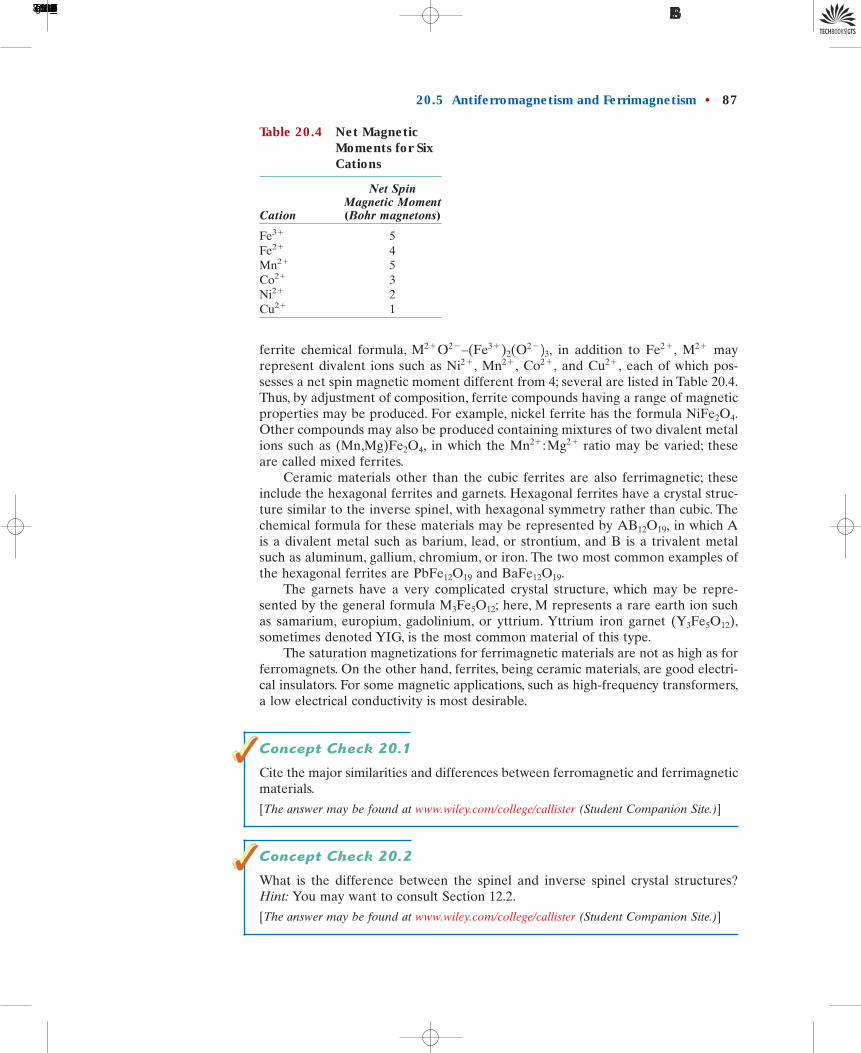
ferrite chemical formula, in addition to mayrepresent divalent ions such as and each of which pos-sesses a net spin magnetic moment different from 4; several are listed in Table 20.4.Thus, by adjustment of composition, ferrite compounds having a range of magneticproperties may be produced. For example, nickel ferrite has the formula Other compounds may also be produced containing mixtures of two divalent metalions such as in which the ratio may be varied; theseare called mixed ferrites.
Ceramic materials other than the cubic ferrites are also ferrimagnetic; theseinclude the hexagonal ferrites and garnets. Hexagonal ferrites have a crystal struc-ture similar to the inverse spinel, with hexagonal symmetry rather than cubic. Thechemical formula for these materials may be represented by in which Ais a divalent metal such as barium, lead, or strontium, and B is a trivalent metalsuch as aluminum, gallium, chromium, or iron. The two most common examples ofthe hexagonal ferrites are and
The garnets have a very complicated crystal structure, which may be repre-sented by the general formula here, M represents a rare earth ion suchas samarium, europium, gadolinium, or yttrium. Yttrium iron garnet sometimes denoted YIG, is the most common material of this type.
The saturation magnetizations for ferrimagnetic materials are not as high as forferromagnets. On the other hand, ferrites, being ceramic materials, are good electri-cal insulators. For some magnetic applications, such as high-frequency transformers,a low electrical conductivity is most desirable.
Concept Check 20.1
Cite the major similarities and differences between ferromagnetic and ferrimagneticmaterials.
[The answer may be found at www.wiley.com/college/callister (Student Companion Site.)]
Concept Check 20.2
What is the difference between the spinel and inverse spinel crystal structures?Hint: You may want to consult Section 12.2.
[The answer may be found at www.wiley.com/college/callister (Student Companion Site.)]
(Y3Fe5O12),M3Fe5O12;
BaFe12O19.PbFe12O19
AB12O19,
Mn2� : Mg2�(Mn,Mg)Fe2O4,
NiFe2O4.
Cu2�,Co2�,Mn2�,Ni2�,M2�Fe2�,M2�O2�–(Fe3�)2(O2� 23,
20.5 Antiferromagnetism and Ferrimagnetism • 87
Table 20.4 Net MagneticMoments for SixCations
Net Spin Magnetic Moment
Cation (Bohr magnetons)
Fe3� 5Fe2� 4Mn2� 5Co2� 3Ni2� 2Cu2� 1
1496T_c20_76-113 10/31/05 16:31 Page 87 FIRST PAGES
88 • Chapter 20 / Magnetic Properties
Saturationmagnetization fora ferrimagneticmaterial (Fe3O4)
Computation of thenumber of Bohrmagnetons per unitcell
EXAMPLE PROBLEM 20.2
Saturation Magnetization Determination for Fe3O4
Calculate the saturation magnetization for given that each cubic unitcell contains 8 and 16 ions, and that the unit cell edge length is0.839 nm.
Solution
This problem is solved in a manner similar to Example Problem 20.1, exceptthat the computational basis is per unit cell as opposed to per atom or ion.
The saturation magnetization will be equal to the product of the numberof Bohr magnetons per cubic meter of and the magnetic moment
per Bohr magneton
(20.11)
Now, is just the number of Bohr magnetons per unit cell divided by theunit cell volume or
(20.12)
Again, the net magnetization results from the ions only. Since thereare 8 ions per unit cell and 4 Bohr magnetons per ion, is 32.Furthermore, the unit cell is a cube, and being the unit cell edgelength. Therefore.
(20.13)
DESIGN EXAMPLE 20.1
Design of a Mixed Ferrite Magnetic Material
Design a cubic mixed-ferrite magnetic material that has a saturation magnetizationof
Solution
According to Example Problem 20.2 the saturation magnetization for isIn order to increase the magnitude of it is necessary to re-
place some fraction of the with a divalent metal ion that has a greater mag-netic moment—for example from Table 20.4, note that there are 5 Bohr
ion as compared to 4 Bohr magnetons/ Let us first em-ploy Equation 20.13 to compute the number of Bohr magnetons per unit cell
Fe2�.magnetons/Mn2�Mn2�;
Fe2�Ms5.0 � 105 A/m.
Fe3O4
5.25 � 105 A/m.
� 5.0 � 105 A/m
�132 Bohr magnetons/unit cell2 19.27 � 10�24 A-m2/Bohr magneton2
10.839 � 10�9 m23/unit cell
Ms �nBmB
a3
VC � a3, anBFe2�Fe2�
Fe2�
N¿ �nB
VC
VC,nBN¿
Ms � N¿mB
mB,Fe3O4,N¿
Fe3�Fe2�Fe3O4
1496T_c20_76-113 10/31/05 16:31 Page 88 FIRST PAGES

20.6 The Influence of Temperature on Magnetic Behavior • 89
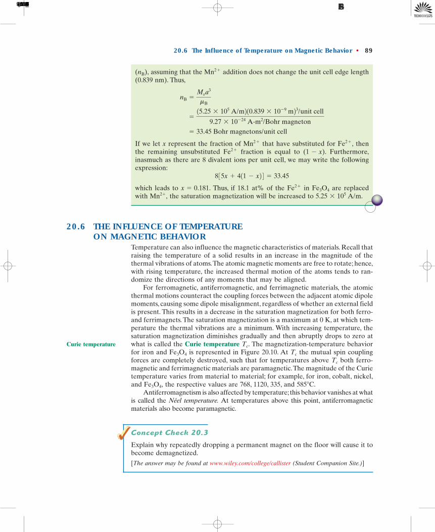
assuming that the addition does not change the unit cell edge length(0.839 nm). Thus,
If we let x represent the fraction of that have substituted for thenthe remaining unsubstituted fraction is equal to Furthermore,inasmuch as there are 8 divalent ions per unit cell, we may write the followingexpression:
which leads to Thus, if 18.1 at% of the in are replacedwith the saturation magnetization will be increased to 5.25 � 105 A/m.Mn2�,
Fe3O4Fe2�x � 0.181.
8 35x � 411 � x2 4 � 33.45
(1 � x).Fe2�Fe2�,Mn2�
� 33.45 Bohr magnetons/unit cell
�15.25 � 105 A/m2 10.839 � 10�9 m23/unit cell
9.27 � 10�24 A-m2/Bohr magneton
nB �Ms
a3
mB
Mn2�(nB),
20.6 THE INFLUENCE OF TEMPERATUREON MAGNETIC BEHAVIOR
Temperature can also influence the magnetic characteristics of materials. Recall thatraising the temperature of a solid results in an increase in the magnitude of thethermal vibrations of atoms.The atomic magnetic moments are free to rotate; hence,with rising temperature, the increased thermal motion of the atoms tends to ran-domize the directions of any moments that may be aligned.
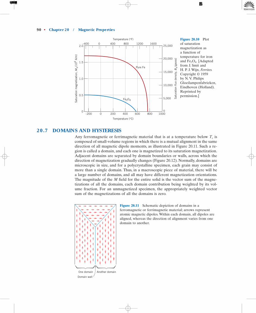
For ferromagnetic, antiferromagnetic, and ferrimagnetic materials, the atomicthermal motions counteract the coupling forces between the adjacent atomic dipolemoments, causing some dipole misalignment, regardless of whether an external fieldis present. This results in a decrease in the saturation magnetization for both ferro-and ferrimagnets. The saturation magnetization is a maximum at 0 K, at which tem-perature the thermal vibrations are a minimum. With increasing temperature, thesaturation magnetization diminishes gradually and then abruptly drops to zero atwhat is called the Curie temperature The magnetization-temperature behaviorfor iron and is represented in Figure 20.10. At the mutual spin couplingforces are completely destroyed, such that for temperatures above both ferro-magnetic and ferrimagnetic materials are paramagnetic.The magnitude of the Curietemperature varies from material to material; for example, for iron, cobalt, nickel,and the respective values are 768, 1120, 335, and
Antiferromagnetism is also affected by temperature; this behavior vanishes at whatis called the Néel temperature. At temperatures above this point, antiferromagneticmaterials also become paramagnetic.
Concept Check 20.3
Explain why repeatedly dropping a permanent magnet on the floor will cause it tobecome demagnetized.
[The answer may be found at www.wiley.com/college/callister (Student Companion Site.)]
585�C.Fe3O4,
Tc
TcFe3O4
Tc.Curie temperature
1496T_c20_76-113 10/31/05 16:31 Page 89 FIRST PAGES
20.7 DOMAINS AND HYSTERESISAny ferromagnetic or ferrimagnetic material that is at a temperature below iscomposed of small-volume regions in which there is a mutual alignment in the samedirection of all magnetic dipole moments, as illustrated in Figure 20.11. Such a re-gion is called a domain, and each one is magnetized to its saturation magnetization.Adjacent domains are separated by domain boundaries or walls, across which thedirection of magnetization gradually changes (Figure 20.12). Normally, domains aremicroscopic in size, and for a polycrystalline specimen, each grain may consist ofmore than a single domain. Thus, in a macroscopic piece of material, there will bea large number of domains, and all may have different magnetization orientations.The magnitude of the M field for the entire solid is the vector sum of the magne-tizations of all the domains, each domain contribution being weighted by its vol-ume fraction. For an unmagnetized specimen, the appropriately weighted vectorsum of the magnetizations of all the domains is zero.
Tc
90 • Chapter 20 / Magnetic Properties
Temperature (°C)
Temperature (°F)
Sat
urat
ion
mag
neti
zati
on,
Ms(1
06 A
/m)
Sat
urat
ion
flux
den
sity
, B
s(g
auss
)
–200 0 200 400
Fe3O4
Pure Fe
600 800 10000
0.5
1.0
1.5
2.0–400 0 400 800 1200 1600
25,000
20,000
15,000
10,000
5,000
0
Figure 20.10 Plotof saturationmagnetization asa function oftemperature for ironand [Adaptedfrom J. Smit andH. P. J. Wijn, Ferrites.Copyright © 1959by N. V. PhilipsGloeilampenfabrieken,Eindhoven (Holland).Reprinted bypermission.]
Fe3O4.
Figure 20.11 Schematic depiction of domains in aferromagnetic or ferrimagnetic material; arrows representatomic magnetic dipoles. Within each domain, all dipoles arealigned, whereas the direction of alignment varies from onedomain to another.
One domain
Domain wall
Another domain
1496T_c20_76-113 10/31/05 16:31 Page 90 FIRST PAGES

Flux density B and field intensity H are not proportional for ferromagnets andferrimagnets. If the material is initially unmagnetized, then B varies as a functionof H as shown in Figure 20.13. The curve begins at the origin, and as H is increased,the B field begins to increase slowly, then more rapidly, finally leveling off and be-coming independent of H. This maximum value of B is the saturation flux density
and the corresponding magnetization is the saturation magnetization men-tioned previously. Since the permeability from Equation 20.2 is the slope of theB-versus-H curve, note from Figure 20.13 that the permeability changes with andis dependent on H. On occasion, the slope of the B-versus-H curve at is spec-ified as a material property, which is termed the initial permeability as indicatedin Figure 20.13.
As an H field is applied, the domains change shape and size by the movementof domain boundaries. Schematic domain structures are represented in the insets(labeled U through Z) at several points along the B-versus-H curve in Figure 20.13.Initially, the moments of the constituent domains are randomly oriented such thatthere is no net B (or M) field (inset U). As the external field is applied, the domainsthat are oriented in directions favorable to (or nearly aligned with) the applied field
mi,H � 0
m
Ms,Bs,
20.7 Domains and Hysteresis • 91
Domainwall
Figure 20.12 The gradual change in magneticdipole orientation across a domain wall. (FromW. D. Kingery, H. K. Bowen, and D. R.Uhlmann, Introduction to Ceramics, 2ndedition. Copyright 1976 by John Wiley &Sons, New York. Reprinted by permission ofJohn Wiley & Sons, Inc.)
©
Figure 20.13 The B-versus-H behavior fora ferromagnetic or ferrimagnetic materialthat was initially unmagnetized. Domainconfigurations during several stages ofmagnetization are represented. Saturationflux density magnetization and initialpermeability are also indicated. (Adaptedfrom O. H. Wyatt and D. Dew-Hughes,Metals, Ceramics and Polymers, CambridgeUniversity Press, 1974.)
mi
Ms,Bs,
Magnetic field strength, H
Flux
den
sity
, B
(or
mag
neti
zati
on,
M)
H = 0
H
�i
H
H
H
V
U
W
X
Y
Z
H
0
Bs (Ms)
1496T_c20_76-113 10/31/05 16:31 Page 91 FIRST PAGES
grow at the expense of those that are unfavorably oriented (insets V through X).This process continues with increasing field strength until the macroscopic speci-men becomes a single domain, which is nearly aligned with the field (inset Y). Sat-uration is achieved when this domain, by means of rotation, becomes oriented withthe H field (inset Z). Alteration of the domain structure with magnetic field for aniron single crystal is shown in the chapter-opening photographs for this chapter.
From saturation, point S in Figure 20.14, as the H field is reduced by reversalof field direction, the curve does not retrace its original path. A hysteresis effect isproduced in which the B field lags behind the applied H field, or decreases at alower rate. At zero H field (point R on the curve), there exists a residual B fieldthat is called the remanence, or remanent flux density, the material remains mag-netized in the absence of an external H field.
Hysteresis behavior and permanent magnetization may be explained by themotion of domain walls. Upon reversal of the field direction from saturation (pointS in Figure 20.14), the process by which the domain structure changes is reversed.First, there is a rotation of the single domain with the reversed field. Next, do-mains having magnetic moments aligned with the new field form and grow at theexpense of the former domains. Critical to this explanation is the resistance tomovement of domain walls that occurs in response to the increase of the mag-netic field in the opposite direction; this accounts for the lag of B with H, or thehysteresis. When the applied field reaches zero, there is still some net volume frac-tion of domains oriented in the former direction, which explains the existence ofthe remanence
To reduce the B field within the specimen to zero (point C on Figure 20.14),an H field of magnitude must be applied in a direction opposite to that of theoriginal field; is called the coercivity, or sometimes the coercive force. Upon con-tinuation of the applied field in this reverse direction, as indicated in the figure, sat-uration is ultimately achieved in the opposite sense, corresponding to point Asecond reversal of the field to the point of the initial saturation (point S) completesthe symmetrical hysteresis loop and also yields both a negative remanence and a positive coercivity
The B-versus-H curve in Figure 20.14 represents a hysteresis loop taken to sat-uration. Of course, it is not necessary to increase the H field to saturation beforereversing the field direction; in Figure 20.15, loop NP is a hysteresis curve corre-sponding to less than saturation. Furthermore, it is possible to reverse the direction
(�Hc).(�Br)
S¿.
Hc
�Hc
Br.
Br;
92 • Chapter 20 / Magnetic Properties
hysteresis
remanence
B
0
Field removal orreversal
Initialmagnetization
R
C
–Br
–Hc
S'
H+Hc
+Br
S
coercivity
Figure 20.14 Magnetic flux densityversus the magnetic field strength for aferromagnetic material that is subjectedto forward and reverse saturations(points S and S�). The hysteresis loopis represented by the solid curve; thedashed curve indicates the initialmagnetization. The remanence Br andthe coercive force Hc are also shown.
1496T_c20_76-113 10/31/05 16:42 Page 92 FIRST PAGES
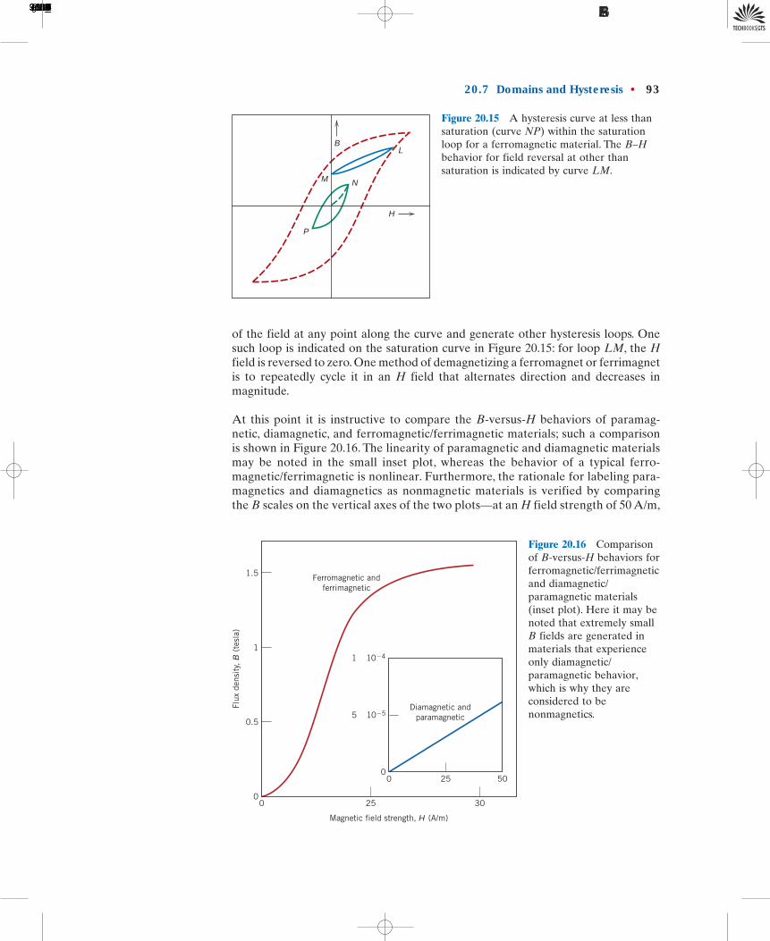
of the field at any point along the curve and generate other hysteresis loops. Onesuch loop is indicated on the saturation curve in Figure 20.15: for loop LM, the Hfield is reversed to zero. One method of demagnetizing a ferromagnet or ferrimagnetis to repeatedly cycle it in an H field that alternates direction and decreases inmagnitude.
At this point it is instructive to compare the B-versus-H behaviors of paramag-netic, diamagnetic, and ferromagnetic/ferrimagnetic materials; such a comparisonis shown in Figure 20.16. The linearity of paramagnetic and diamagnetic materialsmay be noted in the small inset plot, whereas the behavior of a typical ferro-magnetic/ferrimagnetic is nonlinear. Furthermore, the rationale for labeling para-magnetics and diamagnetics as nonmagnetic materials is verified by comparingthe B scales on the vertical axes of the two plots—at an H field strength of 50 A/m,
20.7 Domains and Hysteresis • 93
B
NM
P
H
L
Figure 20.15 A hysteresis curve at less thansaturation (curve NP) within the saturationloop for a ferromagnetic material. The B–Hbehavior for field reversal at other thansaturation is indicated by curve LM.
Figure 20.16 Comparisonof B-versus-H behaviors forferromagnetic/ferrimagneticand diamagnetic/paramagnetic materials(inset plot). Here it may benoted that extremely smallB fields are generated inmaterials that experienceonly diamagnetic/paramagnetic behavior,which is why they areconsidered to benonmagnetics.
1.5
1
0.5
00 25 30
50250
Flux
den
sity
, B
(te
sla)
Ferromagnetic andferrimagnetic
Magnetic field strength, H (A/m)
1 × 10�4
5 × 10�5
0
Diamagnetic andparamagnetic
1496T_c20_76-113 10/31/05 16:31 Page 93 FIRST PAGES
the ferromagnetic/ferrimagnetic materials flux density is on the order of 1.5 tesla,whereas for the parmagnetic and diamagnetic materials it is on the order of
tesla.
Concept Check 20.4
Schematically sketch on a single plot the B-versus-H behavior for a ferromagneticmaterial (a) at 0 K, (b) at a temperature just below its Curie temperature, and(c) at a temperature just above its Curie temperature. Briefly explain why thesecurves have different shapes.
[The answer may be found at www.wiley.com/college/callister (Student Companion Site.)]
Concept Check 20.5
Schematically sketch the hysteresis behavior for a ferromagnet which is graduallydemagnetized by cycling in an H field that alternates direction and decreases inmagnitude.
[The answer may be found at www.wiley.com/college/callister (Student Companion Site.)]
20.8 MAGNETIC ANISOTROPYThe magnetic hysteresis curves discussed in the previous section will have differentshapes depending on various factors: (1) whether the specimen is a single crystal orpolycrystalline; (2) if polycrystalline, any preferred orientation of the grains; (3) thepresence of pores or second-phase particles; and (4) other factors such as temper-ature and, if a mechanical stress is applied, the stress state.
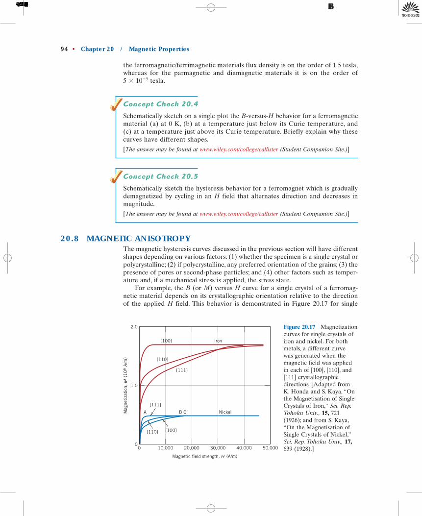
For example, the B (or M) versus H curve for a single crystal of a ferromag-netic material depends on its crystallographic orientation relative to the directionof the applied H field. This behavior is demonstrated in Figure 20.17 for single
5 � 10�5
94 • Chapter 20 / Magnetic Properties
2.0
1.0
0
Mag
neti
zati
on,
M (
10
6 A
/m)
50,00040,00030,00020,00010,0000
Magnetic field strength, H (A/m)
[100]
[110]
[111]
[111]
[100][110]
Iron
A B C Nickel
Figure 20.17 Magnetizationcurves for single crystals ofiron and nickel. For bothmetals, a different curvewas generated when themagnetic field was appliedin each of [100], [110], and[111] crystallographicdirections. [Adapted fromK. Honda and S. Kaya, “Onthe Magnetisation of SingleCrystals of Iron,” Sci. Rep.Tohoku Univ., 15, 721(1926); and from S. Kaya,“On the Magnetisation ofSingle Crystals of Nickel,”Sci. Rep. Tohoku Univ., 17,639 (1928).]
1496T_c20_76-113 10/31/05 16:31 Page 94 FIRST PAGES
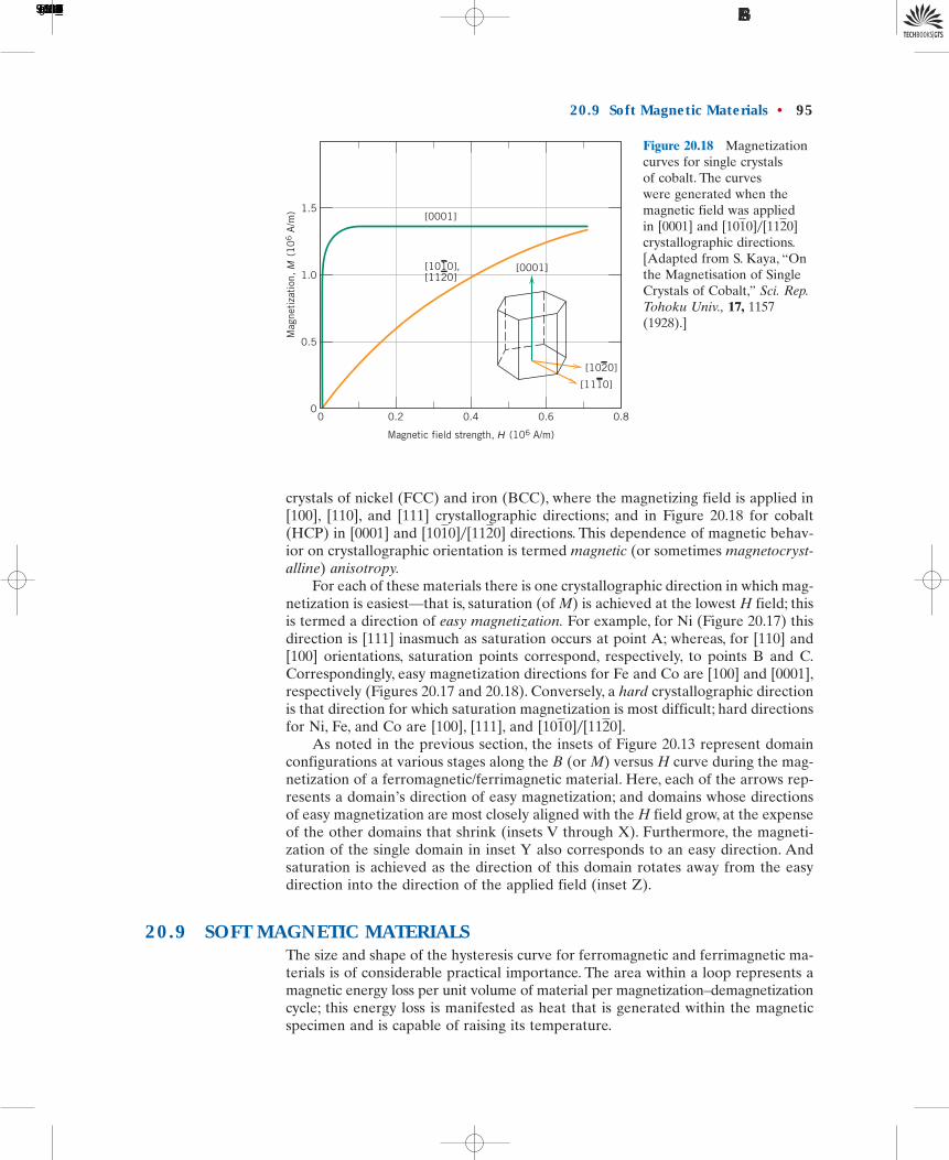
crystals of nickel (FCC) and iron (BCC), where the magnetizing field is applied in[100], [110], and [111] crystallographic directions; and in Figure 20.18 for cobalt(HCP) in [0001] and directions. This dependence of magnetic behav-ior on crystallographic orientation is termed magnetic (or sometimes magnetocryst-alline) anisotropy.
For each of these materials there is one crystallographic direction in which mag-netization is easiest—that is, saturation (of M) is achieved at the lowest H field; thisis termed a direction of easy magnetization. For example, for Ni (Figure 20.17) thisdirection is [111] inasmuch as saturation occurs at point A; whereas, for [110] and[100] orientations, saturation points correspond, respectively, to points B and C.Correspondingly, easy magnetization directions for Fe and Co are [100] and [0001],respectively (Figures 20.17 and 20.18). Conversely, a hard crystallographic directionis that direction for which saturation magnetization is most difficult; hard directionsfor Ni, Fe, and Co are [100], [111], and
As noted in the previous section, the insets of Figure 20.13 represent domainconfigurations at various stages along the B (or M) versus H curve during the mag-netization of a ferromagnetic/ferrimagnetic material. Here, each of the arrows rep-resents a domain’s direction of easy magnetization; and domains whose directionsof easy magnetization are most closely aligned with the H field grow, at the expenseof the other domains that shrink (insets V through X). Furthermore, the magneti-zation of the single domain in inset Y also corresponds to an easy direction. Andsaturation is achieved as the direction of this domain rotates away from the easydirection into the direction of the applied field (inset Z).
20.9 SOFT MAGNETIC MATERIALSThe size and shape of the hysteresis curve for ferromagnetic and ferrimagnetic ma-terials is of considerable practical importance. The area within a loop represents amagnetic energy loss per unit volume of material per magnetization–demagnetizationcycle; this energy loss is manifested as heat that is generated within the magneticspecimen and is capable of raising its temperature.
[1010]�[1120].
[1010]�[1120]
20.9 Soft Magnetic Materials • 95
Mag
neti
zati
on,
M (
10
6 A
/m)
Magnetic field strength, H (106 A/m)
1.5
1.0
0.5
00 0.2 0.4 0.6 0.8
[0001]
[0001][1010],[1120]
[1110]
[1020]
Figure 20.18 Magnetizationcurves for single crystalsof cobalt. The curveswere generated when themagnetic field was appliedin [0001] and crystallographic directions.[Adapted from S. Kaya, “Onthe Magnetisation of SingleCrystals of Cobalt,” Sci. Rep.Tohoku Univ., 17, 1157(1928).]
[1010]�[1120]
1496T_c20_76-113 10/31/05 16:31 Page 95 FIRST PAGES

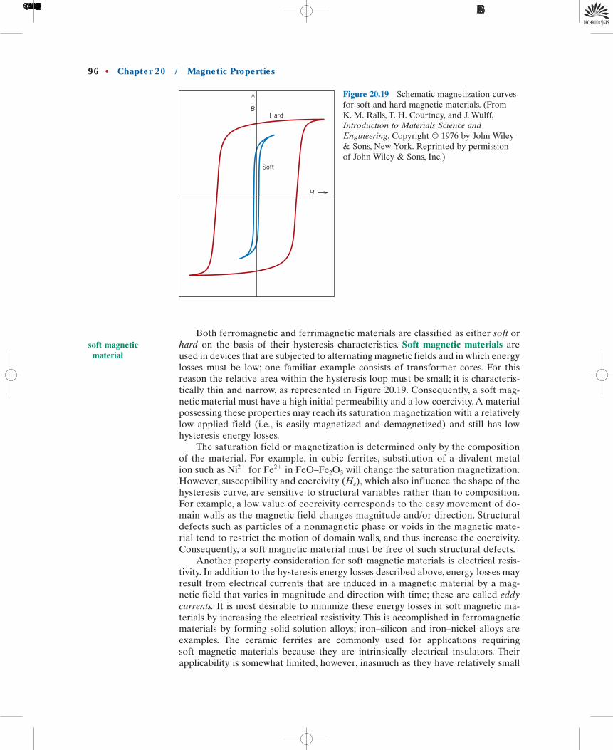
Both ferromagnetic and ferrimagnetic materials are classified as either soft orhard on the basis of their hysteresis characteristics. Soft magnetic materials areused in devices that are subjected to alternating magnetic fields and in which energylosses must be low; one familiar example consists of transformer cores. For thisreason the relative area within the hysteresis loop must be small; it is characteris-tically thin and narrow, as represented in Figure 20.19. Consequently, a soft mag-netic material must have a high initial permeability and a low coercivity.A materialpossessing these properties may reach its saturation magnetization with a relativelylow applied field (i.e., is easily magnetized and demagnetized) and still has lowhysteresis energy losses.
The saturation field or magnetization is determined only by the compositionof the material. For example, in cubic ferrites, substitution of a divalent metalion such as for in will change the saturation magnetization.However, susceptibility and coercivity which also influence the shape of thehysteresis curve, are sensitive to structural variables rather than to composition.For example, a low value of coercivity corresponds to the easy movement of do-main walls as the magnetic field changes magnitude and/or direction. Structuraldefects such as particles of a nonmagnetic phase or voids in the magnetic mate-rial tend to restrict the motion of domain walls, and thus increase the coercivity.Consequently, a soft magnetic material must be free of such structural defects.
Another property consideration for soft magnetic materials is electrical resis-tivity. In addition to the hysteresis energy losses described above, energy losses mayresult from electrical currents that are induced in a magnetic material by a mag-netic field that varies in magnitude and direction with time; these are called eddycurrents. It is most desirable to minimize these energy losses in soft magnetic ma-terials by increasing the electrical resistivity. This is accomplished in ferromagneticmaterials by forming solid solution alloys; iron–silicon and iron–nickel alloys areexamples. The ceramic ferrites are commonly used for applications requiringsoft magnetic materials because they are intrinsically electrical insulators. Theirapplicability is somewhat limited, however, inasmuch as they have relatively small
(Hc),FeO–Fe2O3Fe2�Ni2�
96 • Chapter 20 / Magnetic Properties
Hard
Soft
H
B
Figure 20.19 Schematic magnetization curvesfor soft and hard magnetic materials. (FromK. M. Ralls, T. H. Courtney, and J. Wulff,Introduction to Materials Science andEngineering. Copyright 1976 by John Wiley& Sons, New York. Reprinted by permissionof John Wiley & Sons, Inc.)
©
soft magneticmaterial
1496T_c20_76-113 10/31/05 16:31 Page 96 FIRST PAGES

An Iron-Silicon Alloy That is Used in Transformer Cores
MATERIAL OF IMPORTANCE
As mentioned earlier in this section, trans-former cores require the use of soft magnetic
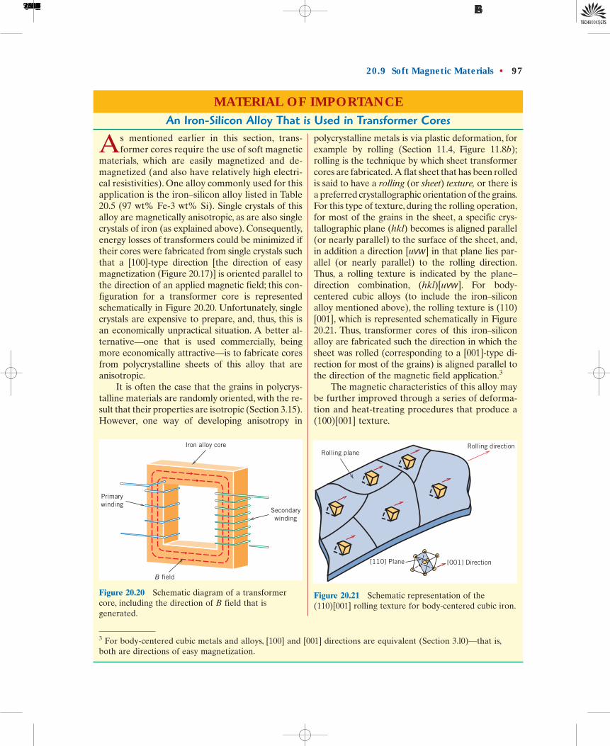
materials, which are easily magnetized and de-magnetized (and also have relatively high electri-cal resistivities). One alloy commonly used for thisapplication is the iron–silicon alloy listed in Table20.5 (97 wt% Fe-3 wt% Si). Single crystals of thisalloy are magnetically anisotropic, as are also singlecrystals of iron (as explained above). Consequently,energy losses of transformers could be minimized iftheir cores were fabricated from single crystals suchthat a [100]-type direction [the direction of easymagnetization (Figure 20.17)] is oriented parallel tothe direction of an applied magnetic field; this con-figuration for a transformer core is representedschematically in Figure 20.20. Unfortunately, singlecrystals are expensive to prepare, and, thus, this isan economically unpractical situation. A better al-ternative—one that is used commercially, beingmore economically attractive—is to fabricate coresfrom polycrystalline sheets of this alloy that areanisotropic.
It is often the case that the grains in polycrys-talline materials are randomly oriented, with the re-sult that their properties are isotropic (Section 3.15).However, one way of developing anisotropy in
polycrystalline metals is via plastic deformation, forexample by rolling (Section 11.4, Figure 11.8b);rolling is the technique by which sheet transformercores are fabricated. A flat sheet that has been rolledis said to have a rolling (or sheet) texture, or there isa preferred crystallographic orientation of the grains.For this type of texture, during the rolling operation,for most of the grains in the sheet, a specific crys-tallographic plane (hkl) becomes is aligned parallel(or nearly parallel) to the surface of the sheet, and,in addition a direction [uvw] in that plane lies par-allel (or nearly parallel) to the rolling direction.Thus, a rolling texture is indicated by the plane–direction combination, (hkl)[uvw]. For body-centered cubic alloys (to include the iron–siliconalloy mentioned above), the rolling texture is (110)[001], which is represented schematically in Figure20.21. Thus, transformer cores of this iron–siliconalloy are fabricated such the direction in which thesheet was rolled (corresponding to a [001]-type di-rection for most of the grains) is aligned parallel tothe direction of the magnetic field application.3
The magnetic characteristics of this alloy maybe further improved through a series of deforma-tion and heat-treating procedures that produce a(100)[001] texture.
Iron alloy core
Secondarywinding
Primarywinding
B field
Rolling planeRolling direction
[001] Direction[110] Plane
Figure 20.20 Schematic diagram of a transformercore, including the direction of B field that isgenerated.
Figure 20.21 Schematic representation of the(110)[001] rolling texture for body-centered cubic iron.
3 For body-centered cubic metals and alloys, [100] and [001] directions are equivalent (Section 3.l0)—that is,both are directions of easy magnetization.
20.9 Soft Magnetic Materials • 97
1496T_c20_76-113 10/31/05 16:31 Page 97 FIRST PAGES
susceptibilities. The properties of a half-dozen soft magnetic materials are shown inTable 20.5.
The hysteresis characteristics of soft magnetic materials may be enhanced forsome applications by an appropriate heat treatment in the presence of a magneticfield. Using such a technique, a square hysteresis loop may be produced, which isdesirable in some magnetic amplifier and pulse transformer applications. In addi-tion, soft magnetic materials are used in generators, motors, dynamos, and switch-ing circuits.
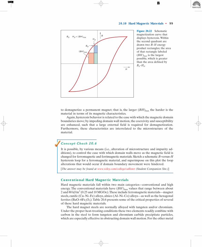
20.10 HARD MAGNETIC MATERIALSHard magnetic materials are utilized in permanent magnets, which must have a highresistance to demagnetization. In terms of hysteresis behavior, a hard magneticmaterial has a high remanence, coercivity, and saturation flux density, as well as alow initial permeability, and high hysteresis energy losses. The hysteresis character-istics for hard and soft magnetic materials are compared in Figure 20.19. The twomost important characteristics relative to applications for these materials are thecoercivity and what is termed the “energy product,” designated as This
corresponds to the area of the largest B-H rectangle that can be constructedwithin the second quadrant of the hysteresis curve, Figure 20.22; its units are kJ/m3
(MGOe).4 The value of the energy product is representative of the energy required
(BH)max
(BH)max.
98 • Chapter 20 / Magnetic Properties
Table 20.5 Typical Properties for Several Soft Magnetic Materials
Initial Relative Saturation HysteresisComposition Permeability Flux Density Bs Loss/Cycle Resistivity �
Material (wt %) �i [tesla (gauss)] [J/m3 (erg/cm3)] (�-m)
Commercial 99.95Fe 150 2.14 270 1.0 � 10�7
iron ingot (21,400) (2700)Silicon–iron 97Fe, 3Si 1400 2.01 40 4.7 � 10�7
(oriented) (20,100) (400)45 Permalloy 55Fe, 45Ni 2500 1.60 120 4.5 � 10�7
(16,000) (1200)Supermalloy 79Ni, 15Fe, 75,000 0.80 — 6.0 � 10�7
5Mo, 0.5Mn (8000)Ferroxcube A 48MnFe2O4, 1400 0.33 �40 2000
52ZnFe2O4 (3300) (�400)Ferroxcube B 36NiFe2O4, 650 0.36 �35 107
64ZnFe2O4 (3600) (�350)
Source: Adapted from Metals Handbook: Properties and Selection: Stainless Steels, Tool Materials and Special-Purpose Metals, Vol. 3, 9th edition, D. Benjamin (Senior Editor), American Society for Metals, 1980.
hard magneticmaterial
4 MGOe is defined as
Furthermore, conversion from cgs–emu to SI units is accomplished by the relationship
1 MGOe � 7.96 kJ/m3
1 MGOe � 106 gauss-oersted
1496T_c20_76-113 10/31/05 16:42 Page 98 FIRST PAGES
to demagnetize a permanent magnet; that is, the larger the harder is thematerial in terms of its magnetic characteristics.
Again, hysteresis behavior is related to the ease with which the magnetic domainboundaries move; by impeding domain wall motion, the coercivity and susceptibilityare enhanced, such that a large external field is required for demagnetization.Furthermore, these characteristics are interrelated to the microstructure of thematerial.
Concept Check 20.6
It is possible, by various means (i.e., alteration of microstructure and impurity ad-ditions), to control the ease with which domain walls move as the magnetic field ischanged for ferromagnetic and ferrimagnetic materials. Sketch a schematic B-versus-Hhysteresis loop for a ferromagnetic material, and superimpose on this plot the loopalterations that would occur if domain boundary movement were hindered.
[The answer may be found at www.wiley.com/college/callister (Student Companion Site.)]
Conventional Hard Magnetic MaterialsHard magnetic materials fall within two main categories—conventional and highenergy. The conventional materials have values that range between about2 and 80 kJ/m3 (0.25 and 10 MGOe).These include ferromagnetic materials—magnetsteels, cunife (Cu–Ni–Fe) alloys, alnico (Al–Ni–Co) alloys—as well as the hexagonalferrites (BaO–6Fe2O3). Table 20.6 presents some of the critical properties of severalof these hard magnetic materials.
The hard magnet steels are normally alloyed with tungsten and/or chromium.Under the proper heat-treating conditions these two elements readily combine withcarbon in the steel to form tungsten and chromium carbide precipitate particles,which are especially effective in obstructing domain wall motion. For the other metal
(BH )max
(BH)max
20.10 Hard Magnetic Materials • 99
B
H
Hd
Bd � Hd < (BH)max
Bd
(BH)max
Figure 20.22 Schematicmagnetization curve thatdisplays hysteresis. Withinthe second quadrant aredrawn two B–H energyproduct rectangles; the areaof that rectangle labeled
is the largestpossible, which is greaterthan the area defined byBd–Hd.
(BH )max
1496T_c20_76-113 10/31/05 16:31 Page 99 FIRST PAGES
alloys, an appropriate heat treatment forms extremely small single-domain andstrongly magnetic iron-cobalt particles within a nonmagnetic matrix phase.
High-Energy Hard Magnetic MaterialsPermanent magnetic materials having energy products in excess of about 80 kJ/m3
(10 MGOe) are considered to be of the high-energy type. These are recentlydeveloped intermetallic compounds that have a variety of compositions; the twothat have found commercial exploitation are SmCo5 and Nd2Fe14B. Their magneticproperties are also listed in Table 20.6.
Samarium–Cobalt MagnetsSmCo5 is a member of a group of alloys that are combinations of cobalt or iron anda light rare earth element; a number of these alloys exhibit high-energy, hard mag-netic behavior,but SmCo5 is the only one of commercial significance. The energyproducts of these SmCo5 materials [between 120 and 240 kJ/m3 (15 and 30 MGOe)]are considerably higher than the conventional hard magnetic materials (Table 20.6);in addition, they have relatively large coercivities. Powder metallurgical techniquesare used to fabricate SmCo5 magnets. The appropriately alloyed material is firstground into a fine powder; the powder particles are aligned using an external mag-netic field and then pressed into the desired shape. The piece is then sintered at anelevated temperature, followed by another heat treatment that improves the mag-netic properties.
Neodymium–Iron–Boron MagnetsSamarium is a rare and relatively expensive material; furthermore, the price of cobaltis variable and its sources are unreliable. Consequently, the Nd2Fe14B alloys havebecome the materials of choice for a large number and wide diversity of applications
100 • Chapter 20 / Magnetic Properties
Table 20.6 Typical Properties for Several Hard Magnetic Materials.
Remanence Coercivity CurieBr Hc (BH)max Temperature Resistivity
Composition [tesla [amp-turn/m [kJ/m3 Te �Material (wt %) (gauss)] (Oe)] (MGOe)] [�C(�F)] (�-m)
Tungsten 92.8 Fe, 0.95 5900 2.6 760 3.0 � 10�7
steel 6 W, 0.5 (9500) (74) (0.33) (1400)Cr, 0.7 C
Cunife 20 Fe, 20 0.54 44,000 12 410 1.8 � 10�7
Ni, 60 Cu (5400) (550) (1.5) (770)Sintered alnico 8 34 Fe, 7 Al, 0.76 125,000 36 860 —
15 Ni, 35 (7600) (1550) (4.5) (1580)Co, 4 Cu,5 Ti
Sintered ferrite 3 BaO–6Fe2O3 0.32 240,000 20 450 �104
(3200) (3000) (2.5) (840)Cobalt rare earth 1 SmCo5 0.92 720,000 170 725 5.0 � 10�7
(9200) (9,000) (21) (1340)Sintered neodymium- Nd2Fe14B 1.16 848,000 255 310 1.6 � 10�6
iron-boron (11,600) (10,600) (32) (590)
Source: Adapted from ASM Handbook, Vol. 2, Properties and Selection: Nonferrous Alloys and Special-PurposeMaterials. Copyright 1990 by ASM International. Reprinted by permission of ASM International, MaterialsPark, OH.
©
1496T_c20_76-113 10/31/05 16:31 Page 100 FIRST PAGES

requiring hard magnetic materials. Coercivities and energy products of thesematerials rival those of the samarium–cobalt alloys (Table 20.6).
The magnetization–demagnetization behavior of these materials is a functionof domain wall mobility, which, in turn, is controlled by the final microstructure—that is, the size, shape, and orientation of the crystallites or grains, as well as the na-ture and distribution of any second-phase particles that are present. Of course,microstructure will depend on how the material is processed. Two different pro-cessing techniques are available for the fabrication of Nd2Fe14B magnets: powdermetallurgy (sintering) and rapid solidification (melt spinning). The powder metal-lurgical approach is similar to that used for the SmCo5 materials. For rapidsolidification, the alloy, in molten form, is quenched very rapidly such that eitheran amorphous or very fine grained and thin solid ribbon is produced. This ribbonmaterial is then pulverized, compacted into the desired shape, and subsequentlyheat treated. Rapid solidification is the more involved of the two fabricationprocesses; nevertheless, it is continuous, whereas powder metallurgy is a batchprocess, which has its inherent disadvantages.
These high-energy hard magnetic materials are employed in a host of differentdevices in a variety of technological fields. One common application is in motors.Permanent magnets are far superior to electromagnets in that their magnetic fieldsare continuously maintained and without the necessity of expending electricalpower; furthermore, no heat is generated during operation. Motors using permanentmagnets are much smaller than their electromagnet counterparts and are utilizedextensively in fractional horsepower units. Familiar motor applications include thefollowing: in cordless drills and screw drivers; in automobiles (starting, windowwinder, wiper, washer, and fan motors); in audio and video recorders; and in clocks.Other common devices that employ these magnetic materials are speakers in audiosystems, lightweight earphones, hearing aids, and computer peripherals.
20.11 MAGNETIC STORAGEWithin the past few years, magnetic materials have become increasingly importantin the area of information storage; in fact, magnetic recording has become virtuallythe universal technology for the storage of electronic information. This is evidencedby the preponderance of audio tapes, VCRs, disk storage media, credit cards, andso on. Whereas in computers, semiconductor elements serve as primary memory,magnetic disks are used for secondary memory because they are capable of storinglarger quantities of information and at a lower cost. Furthermore, the recording andtelevision industries rely heavily on magnetic tapes for the storage and reproduc-tion of audio and video sequences.
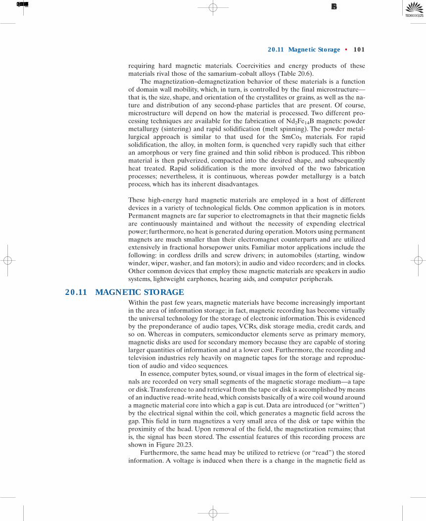
In essence, computer bytes, sound, or visual images in the form of electrical sig-nals are recorded on very small segments of the magnetic storage medium—a tapeor disk.Transference to and retrieval from the tape or disk is accomplished by meansof an inductive read–write head, which consists basically of a wire coil wound arounda magnetic material core into which a gap is cut. Data are introduced (or “written”)by the electrical signal within the coil, which generates a magnetic field across thegap. This field in turn magnetizes a very small area of the disk or tape within theproximity of the head. Upon removal of the field, the magnetization remains; thatis, the signal has been stored. The essential features of this recording process areshown in Figure 20.23.
Furthermore, the same head may be utilized to retrieve (or “read”) the storedinformation. A voltage is induced when there is a change in the magnetic field as
20.11 Magnetic Storage • 101
1496T_c20_76-113 10/31/05 16:31 Page 101 FIRST PAGES
the tape or disk passes by the head coil gap; this may be amplified and then con-verted back into its original form or character. This process is also represented inFigure 20.23.
Recently, hybrid heads that consist of an inductive-write and a magnetoresistiveread head in a single unit have been introduced. In the magnetoresistive head, theelectrical resistance of the magnetoresistive thin film element is changed as a resultof magnetic field changes when the tape or disk passes by the read head. Higher sen-sitivies and higher data transfer rates make magnetoresistive heads very attractive.
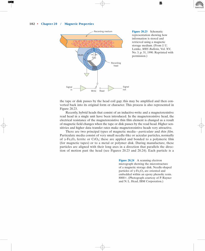
There are two principal types of magnetic media—particulate and thin film.Particulate media consist of very small needle-like or acicular particles, normallyof -Fe2O3 ferrite or CrO2; these are applied and bonded to a polymeric film(for magnetic tapes) or to a metal or polymer disk. During manufacture, theseparticles are aligned with their long axes in a direction that parallels the direc-tion of motion past the head (see Figures 20.23 and 20.24). Each particle is a
g
102 • Chapter 20 / Magnetic Properties
Recording medium
Recordinghead
Signalin Write
Signalout
Read
WidthGap
Figure 20.23 Schematicrepresentation showing howinformation is stored andretrieved using a magneticstorage medium. (From J. U.Lemke, MRS Bulletin, Vol. XV,No. 3, p. 31, 1990. Reprinted withpermission.)
Figure 20.24 A scanning electronmicrograph showing the microstructure of a magnetic storage disk. Needle-shapedparticles of -Fe2O3 are oriented andembedded within an epoxy phenolic resin.8000�. (Photograph courtesy of P. Raynerand N. L. Head, IBM Corporation.)
g
1496T_c20_76-113 10/31/05 16:31 Page 102 FIRST PAGES
single domain that may be magnetized only with its magnetic moment lying alongthis axis. Two magnetic states are possible, corresponding to the saturation mag-netization in one axial direction, and its opposite. These two states make possi-ble the storage of information in digital form, as 1’s and 0’s. In one system, a 1is represented by a reversal in the magnetic field direction from one small areaof the storage medium to another as the numerous acicular particles of each suchregion pass by the head. A lack of reversal between adjacent regions is indicatedby a 0.
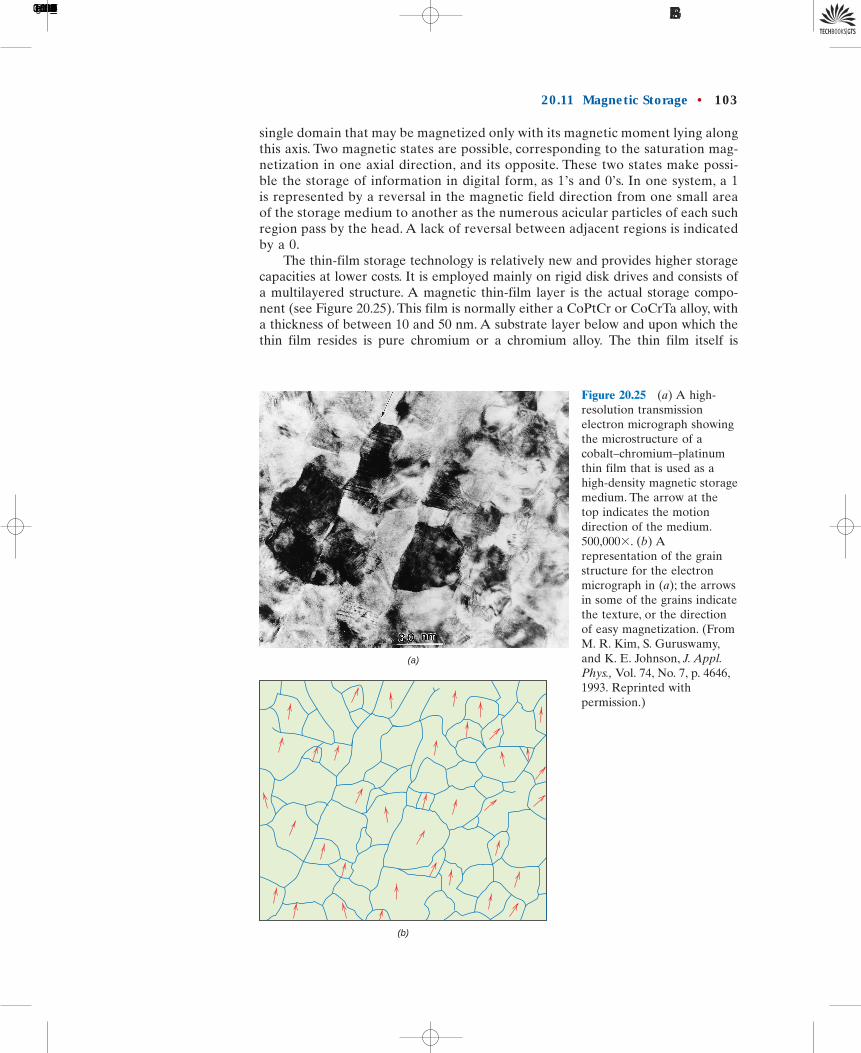
The thin-film storage technology is relatively new and provides higher storagecapacities at lower costs. It is employed mainly on rigid disk drives and consists ofa multilayered structure. A magnetic thin-film layer is the actual storage compo-nent (see Figure 20.25). This film is normally either a CoPtCr or CoCrTa alloy, witha thickness of between 10 and 50 nm. A substrate layer below and upon which thethin film resides is pure chromium or a chromium alloy. The thin film itself is
20.11 Magnetic Storage • 103
(b)
(a)
Figure 20.25 (a) A high-resolution transmissionelectron micrograph showingthe microstructure of acobalt–chromium–platinumthin film that is used as ahigh-density magnetic storagemedium. The arrow at thetop indicates the motiondirection of the medium.500,000�. (b) Arepresentation of the grainstructure for the electronmicrograph in (a); the arrowsin some of the grains indicatethe texture, or the directionof easy magnetization. (FromM. R. Kim, S. Guruswamy,and K. E. Johnson, J. Appl.Phys., Vol. 74, No. 7, p. 4646,1993. Reprinted withpermission.)
1496T_c20_76-113 10/31/05 16:31 Page 103 FIRST PAGES

polycrystalline, having an average grain size that is typically between 10 and 30 nm.Each grain within the thin film is a single magnetic domain, and it is highly desir-able that grain shape and size be relatively uniform. For magnetic storage disks thatemploy these thin films, the crystallographic direction of easy magnetization foreach grain is aligned in the direction of disk motion (or the direction opposite) (seeFigure 20.25). The mechanism of magnetic storage within each of these single-domain grains is the same as for the needle-shaped particles, as described above—that is, the two magnetic states correspond to domain magnetization in one directionor its antiparallel equivalent.
The storage density of thin films is greater than for particulate media becausethe packing efficiency of thin-film domains is greater than for the acicular particles;particles will always be separated with void space in between. At the time of thiswriting, storage densities for particulate media are on the order of bit/in.2
For thin films, storage densities are approximately an order ofmagnitude greater [i.e.,
Regarding specific magnetic properties, the hysteresis loops for these magneticstorage media should be relatively large and square. These characteristics ensurethat storage will be permanent, and, in addition, magnetization reversal will resultover a narrow range of applied field strengths. For particulate recording media,saturation flux density normally ranges from 0.4 to 0.6 tesla (4000 and 6000 gauss).For thin films, will lie between 0.6 and 1.2 tesla (6000 and 12,000 gauss).Coercivity values are typically in the range of to A/m (2000 to3000 Oe).
20.12 SUPERCONDUCTIVITYSuperconductivity is basically an electrical phenomenon; however, its discussion hasbeen deferred to this point because there are magnetic implications relative to thesuperconducting state, and, in addition, superconducting materials are used prima-rily in magnets capable of generating high fields.
As most high-purity metals are cooled down to temperatures nearing 0 K, theelectrical resistivity decreases gradually, approaching some small yet finite valuethat is characteristic of the particular metal. There are a few materials, however, forwhich the resistivity, at a very low temperature, abruptly plunges from a finite valueto one that is virtually zero and remains there upon further cooling. Materials thatdisplay this latter behavior are called superconductors, and the temperature at whichthey attain superconductivity is called the critical temperature 5 The resistivity–temperature behaviors for superconductive and nonsuperconductive materials arecontrasted in Figure 20.26. The critical temperature varies from superconductor tosuperconductor but lies between less than 1 K and approximately 20 K for metalsand metal alloys. Recently, it has been demonstrated that some complex oxideceramics have critical temperatures in excess of 100 K.
At temperatures below the superconducting state will cease upon applica-tion of a sufficiently large magnetic field, termed the critical field which de-pends on temperature and decreases with increasing temperature. The same maybe said for current density; that is, a critical applied current density exists belowJC
HC,TC,
TC.
2.5 � 1051.5 � 105Bs
�5 � 1010 bit/in.2 (8 � 107 bit/mm2)].(1.5 � 105 bit/mm2).
1 � 108
104 • Chapter 20 / Magnetic Properties
superconductivity
5 The symbol is used to represent both the Curie temperature (Section 20.6) and thesuperconducting critical temperature in the scientific literature. They are totally differententities and should not be confused. In this discussion they are denoted by and respectively.
TC,Tc
Tc
1496T_c20_76-113 10/31/05 16:31 Page 104 FIRST PAGES

which a material is superconductive. Figure 20.27 shows schematically the bound-ary in temperature-magnetic field-current density space separating normal and su-perconducting states. The position of this boundary will, of course, depend on thematerial. For temperature, magnetic field, and current density values lying betweenthe origin and this boundary, the material will be superconductive; outside theboundary, conduction is normal.
The superconductivity phenomenon has been satisfactorily explained by meansof a rather involved theory. In essence, the superconductive state results from at-tractive interactions between pairs of conducting electrons; the motions of thesepaired electrons become coordinated such that scattering by thermal vibrations andimpurity atoms is highly inefficient. Thus, the resistivity, being proportional to theincidence of electron scattering, is zero.
On the basis of magnetic response, superconducting materials may be dividedinto two classifications designated as type I and type II. Type I materials, while inthe superconducting state, are completely diamagnetic; that is, all of an applied mag-netic field will be excluded from the body of material, a phenomenon known as theMeissner effect, which is illustrated in Figure 20.28. As H is increased, the materialremains diamagnetic until the critical magnetic field is reached. At this point,conduction becomes normal, and complete magnetic flux penetration takes place.
HC
20.12 Superconductivity • 105
Figure 20.26 Temperaturedependence of the electricalresistivity for normally conductingand superconducting materials inthe vicinity of 0 K.
Temperature (K)
Normal metal
Superconductor
Ele
ctri
cal r
esis
tivi
ty
0 TC0
Current density J
Magnetic field HTemperature T
JC (T = 0 K, H = 0)
HC (T = 0 K, J = 0)
TC (H = 0, J = 0)
Figure 20.27 Criticaltemperature, current density,and magnetic field boundaryseparating superconducting and normal conducting states(schematic).
1496T_c20_76-113 10/31/05 16:31 Page 105 FIRST PAGES

Several metallic elements including aluminum, lead, tin, and mercury belong to thetype I group.
Type II superconductors are completely diamagnetic at low applied fields, andfield exclusion is total. However, the transition from the superconducting state tothe normal state is gradual and occurs between lower critical and upper criticalfields, designated and respectively. The magnetic flux lines begin to pen-etrate into the body of material at and with increasing applied magnetic field,this penetration continues; at field penetration is complete. For fields between
and the material exists in what is termed a mixed state—both normal andsuperconducting regions are present.
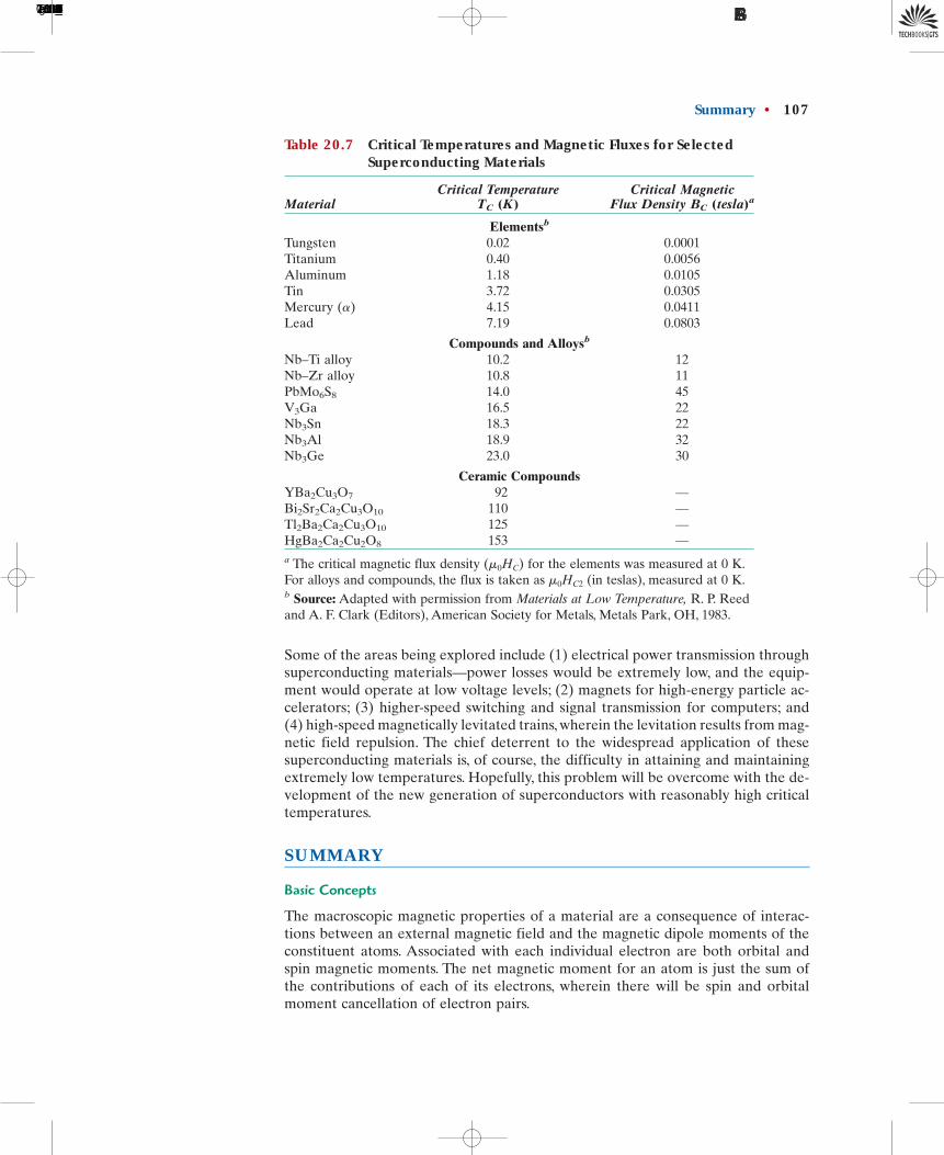
Type II superconductors are preferred over type I for most practical applica-tions by virtue of their higher critical temperatures and critical magnetic fields. Atpresent, the three most commonly utilized superconductors are niobium–zirconium(Nb–Zr) and niobium–titanium (Nb–Ti) alloys and the niobium–tin intermetalliccompound Nb3Sn. Table 20.7 lists several type I and II superconductors, their crit-ical temperatures, and their critical magnetic flux densities.
Recently, a family of ceramic materials that are normally electrically insulativehave been found to be superconductors with inordinately high critical temperatures.Initial research has centered on yttrium barium copper oxide, YBa2Cu3O7, whichhas a critical temperature of about 92 K. This material has a complex perovskite-type crystal structure (Section 12.2). New superconducting ceramic materialsreported to have even higher critical temperatures have been and are currently be-ing developed. Several of these materials and their critical temperatures are listedin Table 20.7. The technological potential of these materials is extremely promisinginasmuch as their critical temperatures are above 77 K, which permits the use ofliquid nitrogen, a very inexpensive coolant in comparison to liquid hydrogen andliquid helium. These new ceramic superconductors are not without drawbacks, chiefof which is their brittle nature. This characteristic limits the ability of these materi-als to be fabricated into useful forms such as wires.
The phenomenon of superconductivity has many important practical implica-tions. Superconducting magnets capable of generating high fields with low powerconsumption are currently being employed in scientific test and research equip-ment. In addition, they are also used for magnetic resonance imaging (MRI) in themedical field as a diagnostic tool. Abnormalities in body tissues and organs can bedetected on the basis of the production of cross-sectional images. Chemical analy-sis of body tissues is also possible using magnetic resonance spectroscopy (MRS).Numerous other potential applications of superconducting materials also exist.
HC 2,HC1
HC 2,HC 1,
HC 2,HC1
106 • Chapter 20 / Magnetic Properties
(b)(a)
Figure 20.28 Representation ofthe Meissner effect. (a) While inthe superconducting state, a bodyof material (circle) excludes amagnetic field (arrows) from itsinterior. (b) The magnetic fieldpenetrates the same body ofmaterial once it becomes normallyconductive.
1496T_c20_76-113 10/31/05 16:31 Page 106 FIRST PAGES

Some of the areas being explored include (1) electrical power transmission throughsuperconducting materials—power losses would be extremely low, and the equip-ment would operate at low voltage levels; (2) magnets for high-energy particle ac-celerators; (3) higher-speed switching and signal transmission for computers; and(4) high-speed magnetically levitated trains, wherein the levitation results from mag-netic field repulsion. The chief deterrent to the widespread application of thesesuperconducting materials is, of course, the difficulty in attaining and maintainingextremely low temperatures. Hopefully, this problem will be overcome with the de-velopment of the new generation of superconductors with reasonably high criticaltemperatures.
S U M M A RY
Basic Concepts
The macroscopic magnetic properties of a material are a consequence of interac-tions between an external magnetic field and the magnetic dipole moments of theconstituent atoms. Associated with each individual electron are both orbital andspin magnetic moments. The net magnetic moment for an atom is just the sum ofthe contributions of each of its electrons, wherein there will be spin and orbitalmoment cancellation of electron pairs.
Summary • 107
Table 20.7 Critical Temperatures and Magnetic Fluxes for SelectedSuperconducting Materials
Critical Temperature Critical MagneticMaterial TC (K) Flux Density BC (tesla)a
Elementsb
Tungsten 0.02 0.0001Titanium 0.40 0.0056Aluminum 1.18 0.0105Tin 3.72 0.0305Mercury (�) 4.15 0.0411Lead 7.19 0.0803
Compounds and Alloysb
Nb–Ti alloy 10.2 12Nb–Zr alloy 10.8 11PbMo6S8 14.0 45V3Ga 16.5 22Nb3Sn 18.3 22Nb3Al 18.9 32Nb3Ge 23.0 30
Ceramic CompoundsYBa2Cu3O7 92 —Bi2Sr2Ca2Cu3O10 110 —Tl2Ba2Ca2Cu3O10 125 —HgBa2Ca2Cu2O8 153 —a The critical magnetic flux density for the elements was measured at 0 K.For alloys and compounds, the flux is taken as (in teslas), measured at 0 K.b Source: Adapted with permission from Materials at Low Temperature, R. P. Reedand A. F. Clark (Editors), American Society for Metals, Metals Park, OH, 1983.
m0HC2
(m0HC)
1496T_c20_76-113 10/31/05 16:31 Page 107 FIRST PAGES

Diamagnetism and Paramagnetism
Diamagnetism results from changes in electron orbital motion that are induced byan external field.The effect is extremely small and in opposition to the applied field.All materials are diamagnetic. Paramagnetic materials are those having permanentatomic dipoles, which are acted on individually and are aligned in the direction ofan external field. Since the magnetizations are relatively small and persist only whilean applied field is present, diamagnetic and paramagnetic materials are consideredto be nonmagnetic.
Ferromagnetism
Large and permanent magnetizations may be established within the ferromagneticmetals (Fe, Co, Ni). Atomic magnetic dipole moments are of spin origin, which arecoupled and mutually aligned with moments of adjacent atoms.
Antiferromagnetism and Ferrimagnetism
Antiparallel coupling of adjacent cation spin moments is found for some ionic ma-terials. Those in which there is total cancellation of spin moments are termed anti-ferromagnetic. With ferrimagnetism, permanent magnetization is possible becausespin moment cancellation is incomplete. For cubic ferrites, the net magnetizationresults from the divalent ions (e.g., Fe2�) that reside on octahedral lattice sites, thespin moments of which are all mutually aligned.
The Influence of Temperature on Magnetic Behavior
With rising temperature, increased thermal vibrations tend to counteract the di-pole coupling forces in ferromagnetic and ferrimagnetic materials. Consequently,the saturation magnetization gradually diminishes with temperature, up to the Curietemperature, at which point it drops to near zero; above these materials areparamagnetic.
Domains and Hysteresis
Below its Curie temperature, a ferromagnetic or ferrimagnetic material is composedof domains—small-volume regions wherein all net dipole moments are mutuallyaligned and the magnetization is saturated. The total magnetization of the solid isjust the appropriately weighted vector sum of the magnetizations of all these domains.As an external magnetic field is applied, domains having magnetization vectors ori-ented in the direction of the field grow at the expense of domains that have unfa-vorable magnetization orientations. At total saturation, the entire solid is a singledomain and the magnetization is aligned with the field direction. The change indomain structure with increase or reversal of a magnetic field is accomplished bythe motion of domain walls. Both hysteresis (the lag of the B field behind the ap-plied H field) as well as permanent magnetization (or remanence) result from theresistance to movement of these domain walls.
Magnetic Anisotropy
The M (or B) versus H behavior for a ferromagnetic single crystal is anisotropic—that is, dependent on the crystallographic direction along which the magnetic fieldis applied. The crystallographic direction for which is achieved at the lowestH field is an easy magnetization direction; for Fe, Ni, and Co easy directions are,respectively, [100], [111], and [0001].
Ms
Tc,
108 • Chapter 20 / Magnetic Properties
1496T_c20_76-113 10/31/05 16:31 Page 108 FIRST PAGES

Soft Magnetic MaterialsHard Magnetic Materials
For soft magnetic materials, domain wall movement is easy during magnetizationand demagnetization. Consequently, they have small hysteresis loops and low en-ergy losses. Domain wall motion is much more difficult for the hard magnetic ma-terials, which results in larger hysteresis loops; because greater fields are requiredto demagnetize these materials, the magnetization is more permanent.
Magnetic Storage
Information storage is accomplished using magnetic materials in both needle-shaped particulate and thin-film forms.
Superconductivity
Superconductivity has been observed in a number of materials, in which, upon coolingand in the vicinity of absolute zero temperature, the electrical resistivity vanishes.The superconducting state ceases to exist if temperature, magnetic field, or currentdensity exceeds the critical value. For type I superconductors, magnetic field exclu-sion is complete below a critical field, and field penetration is complete once isexceeded. This penetration is gradual with increasing magnetic field for type II ma-terials. New complex oxide ceramics are being developed with relatively high criti-cal temperatures, which allow inexpensive liquid nitrogen to be used as a coolant.
HC
References • 109
I M P O R TA N T T E R M S A N D CO N C E P T S
AntiferromagnetismBohr magnetonCoercivityCurie temperatureDiamagnetismDomainFerrimagnetismFerrite (ceramic)
FerromagnetismHard magnetic materialHysteresisMagnetic field strengthMagnetic flux densityMagnetic inductionMagnetic susceptibilityMagnetization
ParamagnetismPermeabilityRemanenceSaturation magnetizationSoft magnetic materialSuperconductivity
R E F E R E N C E S
Azaroff, L. V. and J. J. Brophy, Electronic Processesin Materials, McGraw-Hill Book Company,New York, 1963, Chapter 13. Reprinted byCBLS Publishers, Marietta, OH, 1990.
Bozorth, R. M., Ferromagnetism, Wiley-IEEEPress, New York/Piscataway, NJ, 1993.
Brockman, F. G., “Magnetic Ceramics—A Reviewand Status Report,” American Ceramic SocietyBulletin, Vol. 47, No. 2, February 1968,pp. 186–194.
Chen, C. W., Magnetism and Metallurgy of SoftMagnetic Materials, Dover Publications, NewYork, 1986.
Jiles, D., Introduction to Magnetism and MagneticMaterials, Nelson Thornes, Cheltenham, UK,1998.
Keffer, F., “The Magnetic Properties of Materials,”Scientific American, Vol. 217, No. 3, September1967, pp. 222–234.
Lee, E. W., Magnetism, An Introductory Survey,Dover Publications, New York, 1970.
Morrish, A. H., The Physical Principles of Magnet-ism, Wiley-IEEE Press, New York/Piscataway,NJ, 2001.
1496T_c20_76-113 10/31/05 16:31 Page 109 FIRST PAGES

110 • Chapter 20 / Magnetic Properties
Q U E S T I O N S A N D P R O B L E M S
Basic Concepts
20.1 A coil of wire 0.25 m long and having 400turns carries a current of 15 A.
(a) What is the magnitude of the magneticfield strength H?
(b) Compute the flux density B if the coil isin a vacuum.
(c) Compute the flux density inside a bar ofchromium that is positioned within the coil.The susceptibility for chromium is found inTable 20.2.
(d) Compute the magnitude of the magne-tization M.
20.2 Demonstrate that the relative permeabilityand the magnetic susceptibility are relatedaccording to Equation 20.7.
20.3 It is possible to express the magnetic sus-ceptibility in several different units. Forthe discussion of this chapter, was usedto designate the volume susceptibility in SIunits, that is, the quantity that gives the mag-netization per unit volume (m3) of materialwhen multiplied by H. The mass susceptibil-ity (kg) yields the magnetic moment (ormagnetization) per kilogram of materialwhen multiplied by H; and, similarly, theatomic susceptibility (a) gives the magne-tization per kilogram-mole. The latter twoquantities are related to through therelationships
When using the cgs–emu system, compara-ble parameters exist, which may be desig-nated by (g), and the and
are related in accordance with Table 20.1.From Table 20.2, for copper is
convert this value into theother five susceptibilities.
20.4 (a) Explain the two sources of magneticmoments for electrons.
(b) Do all electrons have a net magneticmoment? Why or why not?
(c) Do all atoms have a net magneticmoment? Why or why not?
�0.96 � 10�5;xm
xm¿xmxm¿ (a);xm¿,, xm¿
xm1a2 � xm1kg2 � atomic weight 1in kg2 xm � xm1kg2 � mass density 1in kg/m32
xm
xm
xm
xm
xm
Diamagnetism and ParamagnetismFerromagnetism
20.5 The magnetic flux density within a bar ofsome material is 0.630 tesla at an H field of
Compute the following for thismaterial: (a) the magnetic permeability, and(b) the magnetic susceptibility. (c) Whattype(s) of magnetism would you suggestis(are) being displayed by this material?Why?
20.6 The magnetization within a bar of somemetal alloy is at an H field of200 A/m. Compute the following: (a) themagnetic susceptibility, (b) the permeability,and (c) the magnetic flux density within thismaterial. (d) What type(s) of magnetismwould you suggest as being displayed by thismaterial? Why?
20.7 Compute (a) the saturation magnetizationand (b) the saturation flux density for iron,which has a net magnetic moment per atomof 2.2 Bohr magnetons and a density of
20.8 Confirm that there are 1.72 Bohr magnetonsassociated with each cobalt atom, given thatthe saturation magnetization is
that cobalt has an HCP crystalstructure with an atomic radius of 0.1253 nmand a c�a ratio of 1.623.
20.9 Assume there exists some hypothetical metalthat exhibits ferromagnetic behavior and thathas (1) a simple cubic crystal structure (Fig-ure 3.23), (2) an atomic radius of 0.125 nm,and (3) a saturation flux density of 0.85 tesla.Determine the number of Bohr magnetonsper atom for this material.
20.10 There is associated with each atom in para-magnetic and ferromagnetic materials a netmagnetic moment. Explain why ferromag-netic materials can be permanently magnet-ized whereas paramagnetic ones cannot.
Antiferromagnetism and Ferrimagnetism
20.11 Consult another reference in which Hund’srule is outlined, and on its basis explain thenet magnetic moments for each of thecations listed in Table 20.4.
106 A/m,1.45 �
7.87 g/cm3.
1.2 � 106 A/m
5 � 105 A/m.
1496T_c20_76-113 10/31/05 16:31 Page 110 FIRST PAGES

20.12 Estimate (a) the saturation magnetization,and (b) the saturation flux density of cobaltferrite [ ], which has a unit celledge length of 0.838 nm.
20.13 The chemical formula for copper ferrite maybe written as because there areeight formula units per unit cell. If this mate-rial has a saturation magnetization of
and a density of 5.40 g/cm3, estimatethe number of Bohr magnetons associatedwith each ion.
20.14 The formula for samarium iron garnetmay be written in the form, where the superscripts a, c,
and d represent different sites on which theSm3� and Fe3� ions are located. The spinmagnetic moments for the Sm3� and Fe3�
ions positioned in the a and c sites are ori-ented parallel to one another and antiparal-lel to the Fe3� ions in d sites. Compute thenumber of Bohr magnetons associated witheach Sm3� ion, given the following informa-tion: (1) each unit cell consists of eight for-mula units; (2) the unit cell iscubic with an edge length of 1.2529 nm;(3) the saturation magnetization for this ma-terial is and (4) assume thatthere are 5 Bohr magnetons associated witheach Fe3� ion.
1.35 � 105 A/m;
(Sm3Fe5O12)
Sm3cFe2
aFe3dO12
(Sm3Fe5O12)
Cu2�
105 A/m1.35 �
(CuFe2O4)8
(CoFe2O4)8
The Influence of Temperature on MagneticBehavior
20.15 Briefly explain why the magnitude of thesaturation magnetization decreases with in-creasing temperature for ferromagnetic ma-terials, and why ferromagnetic behaviorceases above the Curie temperature.
Domains and Hysteresis
20.16 Briefly describe the phenomenon of mag-netic hysteresis, and why it occurs for ferro-magnetic and ferrimagnetic materials.
20.17 A coil of wire 0.5 m long and having 20 turnscarries a current of 1.0 A.
(a) Compute the flux density if the coil iswithin a vacuum.
(b) A bar of an iron–silicon alloy, the B-Hbehavior for which is shown in Figure 20.29,is positioned within the coil. What is the fluxdensity within this bar?
(c) Suppose that a bar of molybdenum isnow situated within the coil. What currentmust be used to produce the same B field inthe Mo as was produced in the iron–siliconalloy (part b) using 1.0 A?
20.18 A ferromagnetic material has a remanenceof 1.0 tesla and a coercivity of 15,000 A/m.Saturation is achieved at a magnetic field
Questions and Problems • 111
Figure 20.29 Initialmagnetization
B-versus-H curve foran iron-silicon alloy. 1.4
0.2 0.4 0.6
1.2
1.0
0.8
0.6
0.4
0.2
0.00 10 20 30 40 50 60
Flux
den
sity
, B
(te
sla)
15,000
10,000
5,000
0
Flux
den
sity
, B
(ga
uss)
Magnetic field strength, H (A/m)
Magnetic field strength, H (oersteds)
1496T_c20_76-113 10/31/05 16:31 Page 111 FIRST PAGES

strength of 25,000 A/m, at which the fluxdensity is 1.25 teslas. Using these data, sketchthe entire hysteresis curve in the range
to �25,000 A/m. Be sure toscale and label both coordinate axes.
20.19 The following data are for a plain carbonsteel alloy:
B BH (A/m) (teslas) H (A/m) (teslas)
0 0 80 0.9015 0.007 100 1.1430 0.033 150 1.3450 0.10 200 1.4160 0.30 300 1.4870 0.63
(a) Construct a graph of B versus H.
(b) What are the values of the initial per-meability and initial relative permeability?
(c) What is the value of the maximumpermeability?
(d) At about what H field does this maxi-mum permeability occur?
(e) To what magnetic susceptibility does thismaximum permeability correspond?
20.20 An iron bar magnet having a coercivity of7000 A/m is to be demagnetized. If the bar isinserted within a cylindrical wire coil 0.25 mlong and having 150 turns, what electric cur-rent is required to generate the necessarymagnetic field?
20.21 A bar of an iron–silicon alloy having the B–Hbehavior shown in Figure 20.29 is insertedwithin a coil of wire 0.40 m long and having50 turns, through which passes a current of0.1 A.
(a) What is the B field within this bar?
(b) At this magnetic field,
(i) What is the permeability?
(ii) What is the relative permeability?
(iii) What is the susceptibility?
(iv) What is the magnetization?
Magnetic Anisotropy
20.22 Estimate saturation values of H for single-crystal nickel in [100], [110], and [111]directions.
H � �25,000
20.23 The energy (per unit volume) required tomagnetize a ferromagnetic material to sat-uration is defined by the followingequation:
That is, is equal to the product of andthe area under an M versus H curve, to thepoint of saturation referenced to the ordi-nate (or M) axis—for example, in Figure20.17 the area between the vertical axis andthe magnetization curve to Estimate values (in J/m3) for single-crystal iron in[100], [110], and [111] directions.
Soft Magnetic MaterialsHard Magnetic Materials
20.24 Cite the differences between hard and softmagnetic materials in terms of both hystere-sis behavior and typical applications.
20.25 Assume the silicon–iron (97Fe, 3Si) in Table20.5 just reaches the point of saturationwhen inserted within the coil in Problem20.1. Compute the saturation magnetization.
20.26 Figure 20.30 shows the B-versus-H curve fora nickel–iron alloy.
(a) What is the saturation flux density?
(b) What is the saturation magnetization?
(c) What is the remanence?
(d) What is the coercivity?
(e) On the basis of data in Tables 20.5 and20.6, would you classify this material as a softor hard magnetic material? Why?
Magnetic Storage
20.27 Briefly explain the manner in which infor-mation is stored magnetically.
Superconductivity
20.28 For a superconducting material at a temper-ature T below the critical temperature the critical field depends on temper-ature according to the relationship
(20.14)
where is the critical field at 0 K.HC(0)
HC1T 2 � HC102 a1 �T 2
TC2b
HC(T),TC,
EsMs.
m0Es
Es � �Ms
0
m0H dM
(Es)
112 • Chapter 20 / Magnetic Properties
1496T_c20_76-113 10/31/05 16:31 Page 112 FIRST PAGES

(a) Using the data in Table 20.7, calculatethe critical magnetic fields for lead at 2.5 and5.0 K.
(b) To what temperature must lead becooled in a magnetic field of 15,000 A/m forit to be superconductive?
20.29 Using Equation 20.29, determine which ofthe superconducting elements in Table 20.7
are superconducting at 2 K and a magneticfield of 40,000 A/m.
20.30 Cite the differences between type I and typeII superconductors.
20.31 Briefly describe the Meissner effect.
20.32 Cite the primary limitation of the new su-perconducting materials that have relativelyhigh critical temperatures.
Design Problems • 113
Figure 20.30 Complete magnetichysteresis loop for a nickel–iron alloy.
H (A/m)
1.6
1.2
0.8
0.4
0
0
�0.4
�20 20 40 60�40�60
�0.8
�1.2
�1.6
B (tesla)
D E S I G N P R O B L E M S
Ferromagnetism
20.D1 A cobalt–iron alloy is desired that has asaturation magnetization of A/m.Specify its composition in weight percentiron. Cobalt has an HCP crystal structurewith c�a ratio of 1.623.Assume that the unitcell volume for this alloy is the same as forpure Co.
1.47 � 106
Ferrimagnetism
20.D2 Design a cubic mixed-ferrite magnetic ma-terial that has a saturation magnetizationof 4.25 � 105 A/m.
1496T_c20_76-113 10/31/05 16:31 Page 113 FIRST PAGES