Embed Size (px)
DESCRIPTION
Micropile Design Calculation
Citation preview

DESIGN AND CONSTRUCTION OF MICRO PILE FOR CLINKER SILO FOUNDATION OF ARABIAN CEMENT COMPANY-RABIGH-EXPANSION
PROJECT -7, RABIGH, KINGDOM OF SAUDI ARABIA
DESIGN OF MICRO PILE
(R-15-070)
CLINKER SILO FOUNDATION ACCREP 7, RABIGH
Prepared for:
China National Building Material Company LimitedRiyadh, Kingdom of Saudi Arabia
Client File # R-15-070 26th October, 2015
Document #R-15-070Revision #2Page #1

DESIGN AND CONSTRUCTION OF MICRO PILE FOR CLINKER SILO FOUNDATION OF ARABIAN CEMENT COMPANY-RABIGH-EXPANSION
PROJECT -7, RABIGH, KINGDOM OF SAUDI ARABIA
1. PROJECT & DESIGN INTRODUCTION
CNBM entrusted Omar Jazzar Consulting Engineers for the design and installation of Micropile for
Clinker Silo Foundation of Arabian Cement Company – Rabigh – Expansion Project – 7. In view of
this, the following design assumptions/facts are used herein.
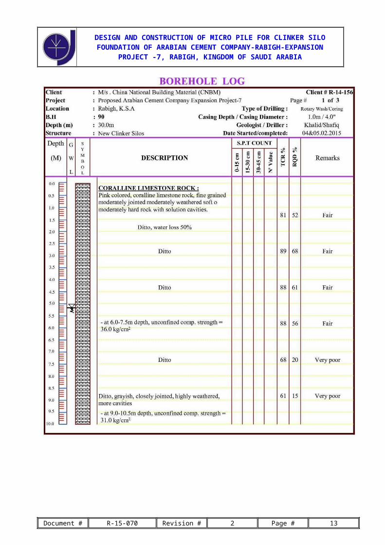
a. Geotechnical Investigation Report # R-14-156– Rev - 3
b. Reference Boreholes - BH 88 - 90 (annexed with this design)
c. Depth of the clinker silo foundation as per the approved drawings is 4.5 m below the FFL
d. Reference Design Document – “Micropile Design & Construction by U.S. Department of
Transportation – Federal Highway Administration – Publication # FHWA-NHI-05-039-
December 2005”
2. STRUCTURAL DESIGN OF MICROPILE
a. The allowable compression load of a Micropile is given by the following empirical equation
Pc-allowable = 0.4 f’c-concrete x Aconcrete + 0.47 Fy-steel x Abar
Where
Pc-allowable = allowable compression load;
f’c-concrete = unconfined compressive strength of concrete (typically a 28-day strength) = 20 MPa. This
is considered for the design only but has been revised to 35 MPa as per the construction drawings.
Aconcrete = area of concrete in Micropile cross section = 16867.211 mm2
Fy-steel = yield strength of steel rebar = 420 MPa
Abar = cross sectional area of steel rebar = 804.247 mm2
Hence Pc-allowable = 0.4 x 20 x 16867.211 + 0.47 x 420 x 804.247 = 293696.046 N = 293. 7 kN
However the design compression load on the micropile shall be limited to 200 kN
b. The allowable Tension load shall be calculated by the following empirical relation
Pt-allowable = 0.55x Fy-steel x Abar
And Pt-allowable = 0.55 x 420 x 804.247 = 185781.057 N = 185.8 kN; Limit to 150 kN for tension
load. However there is no uplift load on the micropile. The above design features the internal
capacity of micropile and the external design capacity shall be verified by a load test on site. The
load factors applied as per the design document reference.
Document #R-15-070Revision #2Page #2

DESIGN AND CONSTRUCTION OF MICRO PILE FOR CLINKER SILO FOUNDATION OF ARABIAN CEMENT COMPANY-RABIGH-EXPANSION
PROJECT -7, RABIGH, KINGDOM OF SAUDI ARABIA
3. EVALUATE GEOTECHNICAL CAPACITY OF MICROPILE
The subsurface stratum is “Coralline Limestone Rock” and the type of grouting shall be gravity
grouting, as per the design reference “Type A” Grout-to-Ground Bond Ultimate Strength shall be
used. Considering the existing subsurface strata as very dense gravel due to the inconsistent rock
quality below the founding level we have
Grout-to-Ground Bond Ultimate Strength bond = 250 kPa= 0.25 MPa
The bond length is given by
Lb = PG-allowable x FS/ bond x x Db
Where
Lb = Bond Length
PG-allowable = Allowable geotechnical bond capacity which is the maximum compression or tension
load for design = 200 kN
FS = Factor of Safety = 2.5
bond = Grout-to-Ground Bond Ultimate Strength = 250 kPa = 0.25 MPa
Db= Diameter of the drill hole = 150 mm
We have Lb = 200 x 2.5 / 250 x x 0.150 = 4.25 m;
Hence adopt 5.0 m bond length for micropile.
4. TESTING OF MICROPILE
The test arrangement is generally by a hydraulic jack and reaction load. The actual micro pile
capacity and external design capacity shall be validated by a load test. A minimum of 10 test shall be
done and can be increased depending upon the consistency of test results. Ultimate and or
verification shall be done before and during the installation of micropiles. Proof test shall be done
during the installation program of micropiles.
5. ALLOWANCE FOR CORROSION
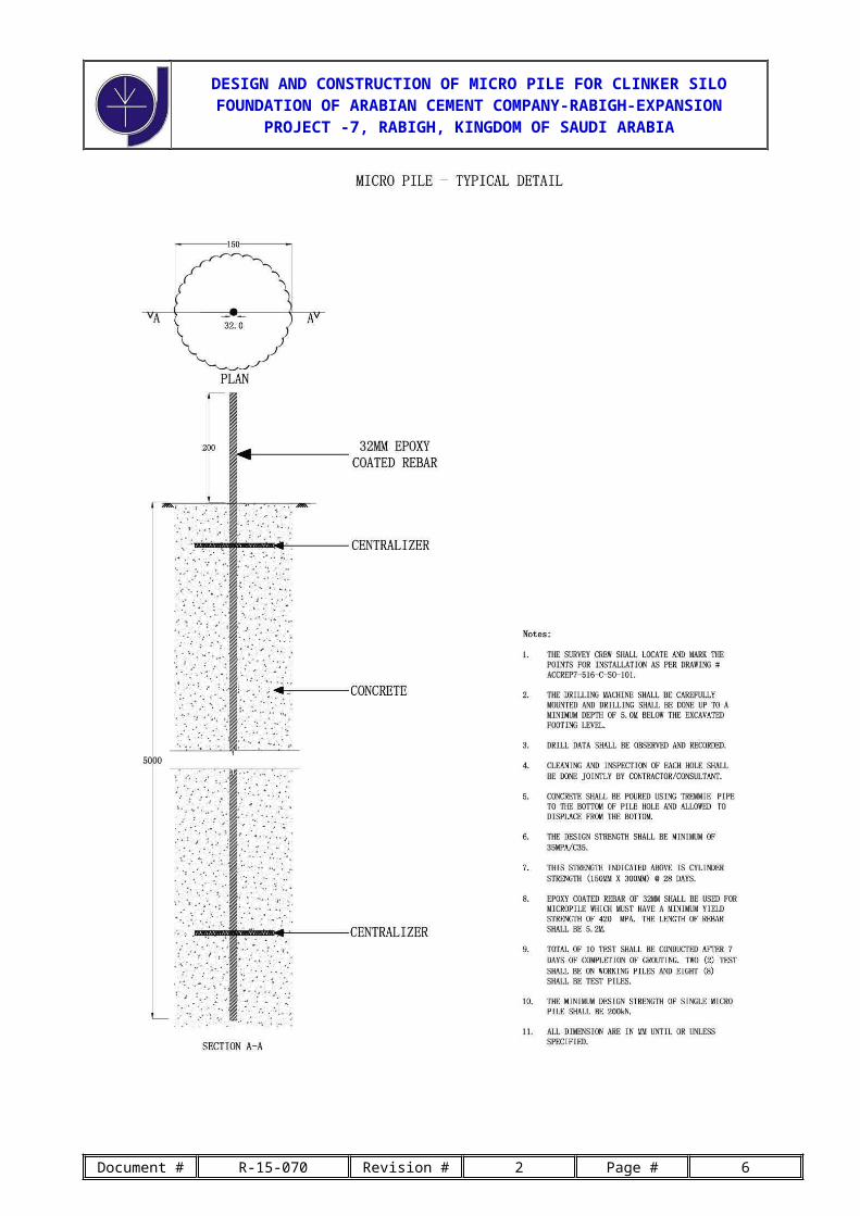
The 32 mm rebar shall used with epoxy coating for the central reinforcement of the micropile since
we have high aggressive substratum (rock and ground water) is existence.
Document #R-15-070Revision #2Page #3

DESIGN AND CONSTRUCTION OF MICRO PILE FOR CLINKER SILO FOUNDATION OF ARABIAN CEMENT COMPANY-RABIGH-EXPANSION
PROJECT -7, RABIGH, KINGDOM OF SAUDI ARABIA
Document #R-15-070Revision #2Page #4

DESIGN AND CONSTRUCTION OF MICRO PILE FOR CLINKER SILO FOUNDATION OF ARABIAN CEMENT COMPANY-RABIGH-EXPANSION
PROJECT -7, RABIGH, KINGDOM OF SAUDI ARABIA
Document #R-15-070Revision #2Page #5
DESIGN AND CONSTRUCTION OF MICRO PILE FOR CLINKER SILO FOUNDATION OF ARABIAN CEMENT COMPANY-RABIGH-EXPANSION
PROJECT -7, RABIGH, KINGDOM OF SAUDI ARABIA
Document #R-15-070Revision #2Page #6

DESIGN AND CONSTRUCTION OF MICRO PILE FOR CLINKER SILO FOUNDATION OF ARABIAN CEMENT COMPANY-RABIGH-EXPANSION
PROJECT -7, RABIGH, KINGDOM OF SAUDI ARABIA
Document #R-15-070Revision #2Page #7

DESIGN AND CONSTRUCTION OF MICRO PILE FOR CLINKER SILO FOUNDATION OF ARABIAN CEMENT COMPANY-RABIGH-EXPANSION
PROJECT -7, RABIGH, KINGDOM OF SAUDI ARABIA
Document #R-15-070Revision #2Page #8

DESIGN AND CONSTRUCTION OF MICRO PILE FOR CLINKER SILO FOUNDATION OF ARABIAN CEMENT COMPANY-RABIGH-EXPANSION
PROJECT -7, RABIGH, KINGDOM OF SAUDI ARABIA
Document #R-15-070Revision #2Page #9

DESIGN AND CONSTRUCTION OF MICRO PILE FOR CLINKER SILO FOUNDATION OF ARABIAN CEMENT COMPANY-RABIGH-EXPANSION
PROJECT -7, RABIGH, KINGDOM OF SAUDI ARABIA
Document #R-15-070Revision #2Page #10

DESIGN AND CONSTRUCTION OF MICRO PILE FOR CLINKER SILO FOUNDATION OF ARABIAN CEMENT COMPANY-RABIGH-EXPANSION
PROJECT -7, RABIGH, KINGDOM OF SAUDI ARABIA
Document #R-15-070Revision #2Page #11

DESIGN AND CONSTRUCTION OF MICRO PILE FOR CLINKER SILO FOUNDATION OF ARABIAN CEMENT COMPANY-RABIGH-EXPANSION
PROJECT -7, RABIGH, KINGDOM OF SAUDI ARABIA
Document #R-15-070Revision #2Page #12
DESIGN AND CONSTRUCTION OF MICRO PILE FOR CLINKER SILO FOUNDATION OF ARABIAN CEMENT COMPANY-RABIGH-EXPANSION
PROJECT -7, RABIGH, KINGDOM OF SAUDI ARABIA
Document #R-15-070Revision #2Page #13