Embed Size (px)
Citation preview
15
Rocket Testing and Integrated System Health Management
Fernando Figueroa1 and John Schmalzel2
1 NASA Stennis Space Center, Stennis Space Center MS, 39529, USA Email: [email protected] 2 Rowan University Glassboro, NJ 08028, USA Email: [email protected]
Abstract Integrated System Health Management (ISHM) describes a set of system capabilities that in aggregate perform: determination of condition for each system element, detection of anomalies, diagnosis of causes for anomalies, and prognostics for future anomalies and system behavior. The ISHM should also provide operators with situational awareness of the system by integrating contextual and timely data, information, and knowledge (DIaK) as needed. ISHM capabilities can be implemented using a variety of technologies and tools. This chapter provides an overview of ISHM contributing technologies and describes in further detail a novel implementation architecture along with associated taxonomy, ontology, and standards. The operational ISHM testbed is based on a subsystem of a rocket engine test stand. Such test stands contain many elements that are common to manufacturing systems, and thereby serve to illustrate the potential benefits and methodologies of the ISHM approach for intelligent manufacturing.
15.1 Introduction
Integrated system health management (ISHM) addresses health management of systems, particularly of high complexity encompassing large numbers of items such as actuators, pumps, pipes, tanks, instruments, sensors, and functional processes. These are collectively termed system "elements". Determining the impact of element degradation and anomalies is the fundamental problem that ISHM addresses. ISHM should detect impending failures, identify anomalies and failures when they occur, diagnose root cause, predict future element failures, and provide historical records of operation for each element in a system including data and the associated events that contribute to the determination of condition. However, the most important role of an ISHM is to provide insight into the state of a system to answer key questions
https://ntrs.nasa.gov/search.jsp?R=20050238486 2018-09-18T23:36:17+00:00Z
374 Fernando Figueroa and John Schmalzel
including: “What can the system do now? How safe is it? What are ways to work around degraded elements and failures?”
Failures of system elements normally occur over time as the result of progressive degradation; for example, stress fractures resulting from cyclic loading. ISHM is concerned with managing the interplay between data, information, and knowledge (DIaK) in order to make possible detection, prediction, and response to failures. Data flows into an ISHM from a variety of sensors, which can include real-time data and historical data from collections of archival system files. Similarly, the ISHM needs access to knowledge bases that contain descriptions of elements, models for behaviors of interest, and examples of nominal and off-nominal behaviors. Sensor data combined with system-wide knowledge is operated on to develop information about the system. Further processing based on methods for information fusion, inference, and decision making, provides insight into system state and detects anomalous conditions that may signify future failure. When failures do occur, the ISHM shifts to determination of system impacts and recommendations for possible courses of action.
The authors contend the Integrated System Health Management philosophy to be predicated on:
• Lives and missions depend on vigilant systems. • Data is valuable: No data should be left uninterpreted. • Information is hidden: Intelligence is required to extract information. • Interpretation, reasoning, and decision making require knowledge of how
elements interact as part of an integrated system. ISHM is a set of capabilities that indicates how well a system can perform the
following suite of functions: • Evaluate condition of system elements. • Detect anomalies and their causes. • Identify overall system state. • Predict system impacts. • Recommend responses to mitigate anomaly and failure effects. • Communicate contextual and timely DIaK and situational awareness to
system elements and system operators. Increasing complexity and automation is required to achieve more demanding
civilian and military technology objectives. NASA must push technology limits to deploy advanced systems-of-systems (SoS) to achieve its goals. The Space Shuttle, the International Space Station (ISS), and Rocket Engine Test Stands (RETS), are current examples. These complex SoS call for large life-cycle investments – especially for crew-rated spacecraft – and require large teams of human experts and support resources for monitoring, assessing, maintaining, upgrading, and operating.
NASA’s Exploration Systems Mission Directorate (ESMD) [15.1] is currently focused on development of technologies for products to fulfill President Bush’s New Vision for Exploration. The Exploration Systems Research and Technology (ESR&T) Program has defined specific capabilities needed; one of them is Integrated System Health Management (ISHM). ISHM approaches need to be
Rocket Testing and Integrated System Health Management 375
matured to enable NASA's new Exploration Mission, which includes requirements for long-duration robotic-assisted human space travel with increased safety and decreased life cycle costs. ISHM is essential for dealing with SoS. ISHM is about knowing the condition of every element of the SoS at all times. It is about embedding knowledge and information so that systems can apply human-inspired strategies to monitor, capture anomalies, diagnose sources of anomalies, and predict future status. It is also about providing users with an integrated situational awareness of the SoS, and of every element in the context of its function within the SoS. It is appropriate to embed intelligence throughout SoS elements to achieve an overall ISHM capability. Use of a distributed intelligence approach also embodies other important attributes such as modularity, flexibility, and obtaining affordable life-cycle costs.
Although the focus of this book is on intelligent manufacturing systems, this chapter refers to systems most often associated with the aerospace industry when describing the background, needs, and benefits of ISHM. In particular, the application environment of rocket engine test consists of complex pipe, valve, and control networks for the delivery of gases and liquids for a spectrum of pressures, temperatures, and mass flow rate requirements. Since many manufacturing systems share similar elements, ISHM for rocket testing is directly applicable to condition-based monitoring and control for intelligent manufacturing.
15.2 Background
The broad field of condition based maintenance has been extended and modified to support unique requirements for specialized applications. As one example, work on integrated vehicle health management (IVHM) systems for space applications started in the 1980’s and continues today [15.2]. Similarly, the core ISHM activity of identifying unique features by monitoring and processing sensor data to detect anomalies is widely performed using a variety of standard algorithms, e.g., use of statistical measures, trend analysis, identification of time constants, and measurement of noise, are but a few of the many techniques available [15.3][15.4]. Integration of data from multiple sources to make better-informed decision is broadly termed sensor fusion; there is a large body of publications in this area [15.5]-[15.7]. Extracted features are input to multiple classifier systems [15.8] and other structures for purposes of reasoning about anomaly sources (diagnosis) and future implications (prognosis) and may include guidance on the actions required to maintain the system as close as possible to the desired performance goals.
These and related methodologies have generally been applied to detect anomalies on individual elements of a system (e.g., pumps, valves, airfoils). The challenge is to integrate these methods with embedded information and knowledge to implement an ISHM that can determine the health of every element and perform system-wide diagnosis and prognosis. Because of the complexity of the systems-of-systems approach required, ISHM remains an emerging area of research and development with relatively few operational implementations available. These examples provide basic capability by monitoring a subset of signals; malfunctions are indicated when certain key variables exceed fixed thresholds. Reaction responses are typically simplistic including process shutdown and event logging.
376 Fernando Figueroa and John Schmalzel
Among the most sophisticated of current ISHM implementations are those designed for the Boeing 777 [15.9][15.10], Northrop Grumman’s B2 [15.11], and the Boeing Rocketdyne Space Shuttle Main Engine (SSME) [15.12]-[15.14]. The goals of the airplane health management (AHM) system include an ambitious reduction in unplanned maintenance from 75% to 25% of current levels. The AHM system operates on the onboard data collected by the central maintenance computer from the distributed built-in test components. First-generation threshold detection approaches have evolved to data mining that operates on real-time data transmitted from an in-flight aircraft in conjunction with the large database collected from the entire fleet. Achieving the 75% to 25% goal requires integration across subsystems. For example, a power bus shared between two systems means that anomalies reported from one subsystem need to be linked to analysis of anomalies in the other subsystem. Extension of the 777’s AHM approach to other complex systems such as spacecraft or advanced manufacturing is likely to be difficult because there is no reported open architecture that supports scalability and flexibility.
Development of an ISHM for the SSME was defined as part of long-term goals for enhancing reliability and extending operational life of the Space Shuttle. The work was phased to achieve near-term reliability enhancements while making future ISHM upgrades possible through an additional communication interface to the engine controller. However, it is unlikely that further development work will continue due to the planned phase out of shuttle operations by 2010. A new initiative to develop a replacement Crew Exploration Vehicle (CEV) will undoubtedly incorporate many of the lessons learned during the SSME ISHM development.
NASA’s long interest in health management provides several other examples of ISHM-related development efforts. During the X33 program, NASA tested potential ISHM technologies that could be used to assess structural health of wings. Experiments produced equipment to collect data from distributed fiber optic strain gages thereby flight testing sensors, interconnects, signal processing electronics, and supporting computer system [15.15]. In another effort, the Propulsion IVHM Technology Experiment (PITEX) program implemented an integrated health management architecture that represented system elements with state models in order to detect anomalies and their sources. The prototype implementation incorporated Livingstone as the software environment to address a propulsion system composed of tanks, valves, and other basic elements; it was tested using simulated data [15.16].
NASA, joint with Australia’s Commonwealth Scientific and Industrial Research Organization (CSIRO), investigated detection of structural damage on aircraft skins [15.17]. Consisting of distributed piezoelectric sensors mounted on the inside of aluminium plates, groups of four sensors shared data acquisition and processing, and communication with neighbouring boxes. This work explored novel sensors and the means to embed sensor intelligence. More importantly, the collaboration considered network technologies for management of sensor data, information, and knowledge, while focusing on detection of surface damage.
A significant pattern in the latest ISHM work is a shift toward distributed intelligence. For example, MIT’s Draper Laboratory proposed intelligent spacecraft encompassing networked intelligent components [15.18]. This is a fundamental departure from current spacecraft, such as the Space Shuttle, which are highly
Rocket Testing and Integrated System Health Management 377
centralized architectures with individual sensors connected to central analog and digital processing equipment interconnected with MIL-STD-1553 data buses. The advance proposed by MIT is an architecture composed of intelligent nodes to support distributed processing at the sensor. Considerations included sensors and actuators with embedded processing, and digital communication among sensors, actuators, and computers. Key components of the novel architecture included two-wire power and data networks; fault-tolerant organization; smart sensors based on IEEE-1451 standards [15.19][15.20]; and packaging considerations. A laboratory prototype network with intelligent nodes was developed and tested to substantiate the benefits of the approach and found reduced wiring, weight, and complexity; increased reliability and safety; improved health management as measured by reduced operational costs; reduced software complexity and cost; and simplified vehicle development and integration. Other anticipated long-term benefits to an open architecture designed to support evolution is the flexibility to add new capabilities. More recently, the National Science Foundation (NSF) has begun promoting research on novel architectures that include intelligent sensors [15.21].
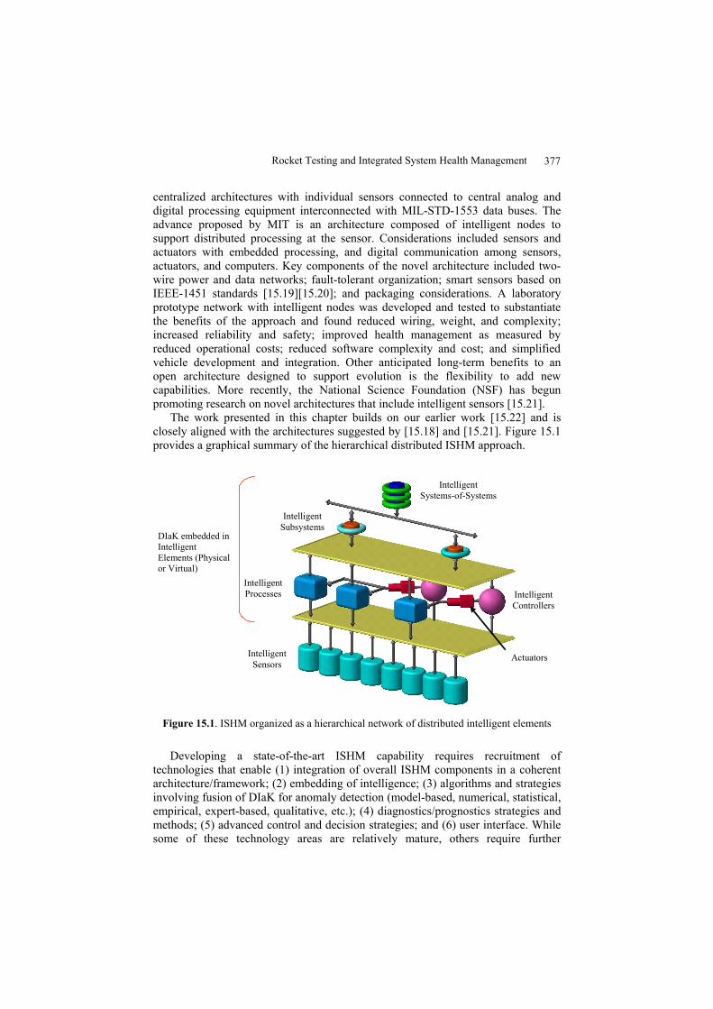
The work presented in this chapter builds on our earlier work [15.22] and is closely aligned with the architectures suggested by [15.18] and [15.21]. Figure 15.1 provides a graphical summary of the hierarchical distributed ISHM approach.
Intelligent Sensors
Intelligent Processes Intelligent
Controllers
Intelligent Subsystems
Intelligent Systems-of-Systems
Actuators
DIaK embedded in Intelligent Elements (Physical or Virtual)
Figure 15.1. ISHM organized as a hierarchical network of distributed intelligent elements
Developing a state-of-the-art ISHM capability requires recruitment of technologies that enable (1) integration of overall ISHM components in a coherent architecture/framework; (2) embedding of intelligence; (3) algorithms and strategies involving fusion of DIaK for anomaly detection (model-based, numerical, statistical, empirical, expert-based, qualitative, etc.); (4) diagnostics/prognostics strategies and methods; (5) advanced control and decision strategies; and (6) user interface. While some of these technology areas are relatively mature, others require further
378 Fernando Figueroa and John Schmalzel
development and theoretical underpinning. In particular, integration of an appropriate architecture and embedding of intelligence are key challenges to achieving credible ISHM capabilities. These and other issues are addressed in the embodiment described.
15.3 ISHM for Rocket Test
15.3.1 Implementation Strategy
This work began as a project to develop ISHM support for rocket engine testing that included smart sensors in the architecture. The Integrated Health with Networked Intelligent Elements (IHNIE) system is based on a generic taxonomy, framework, and methodologies to implement an ISHM. The proof of concept focuses on – among others – the hydraulic system for a test stand (Stennis Space Center), which provides facility fluid motive power to actuate valves that control propellant, oxidizer, and purge gases and/or liquids. The IHNIE system is organized in the hierarchical format of Figure 15.1. The framework and associated methodologies make possible the flow of information and knowledge among the elements of the system to determine element condition.
Developing ISHM capability shares many features in common with other complex system designs, but differs radically because of the need to evolve the DIaK content. Core ISHM technologies need to be integrated using available DIaK, yet the DIaK continues to evolve during SoS operation. Achieving optimum ISHM performance requires systematic adaptation to better exploit new knowledge gained by continuing experience with a system. Developing such an evolutionary system is beyond the scope of the current project focus, but is a long-term vision of what ISHM capability should include.
To this end, the prototype ISHM development seeks to (1) Mature core technologies that provide the infrastructure required for a
flexible/evolutionary ISHM system. (2) Use the core technologies to develop prototypes for well-characterized,
reasonably-complex systems with historical DIaK, available expertise, and which are in continuous operation.
(3) Port validated ISHM technologies to other systems (e.g. manufacturing facilities, spacecraft) while maintaining and evolving the prototypes and testbeds.
15.3.2 DIaK Architecture
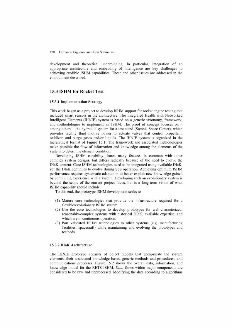
The IHNIE prototype consists of object models that encapsulate the system elements, their associated knowledge bases, generic methods and procedures, and communications processes. Figure 15.2 shows the overall data, information, and knowledge model for the RETS ISHM. Data flows within major components are considered to be raw and unprocessed. Modifying the data according to algorithms
Rocket Testing and Integrated System Health Management 379
transforms the data to information, which is the desired exchange commodity, for example, conversion of raw sensor voltage readings to meaningful engineering units. Another significant factor is the availability of knowledge and its use. For example, armed with new information about parameters of the SoS, compilations of expert interpretations with system design files would provide the context to determine the actual SoS state. The explicit flow of data and health information with counterflow of evaluation and guidance is an important facet of the architecture. Higher architecture layers (right side of Figure 15.2) are in a better position to evaluate elements to determine condition and develop measures of trust for lower levels.
SensorIEF, IDM
Process IEF, IDM
SystemIEF, IDM
SensorCondition
ProcessCondition
System Condition
IEF, IDM forbest values
Cooperative &Competitive
Sensors
SensorKnowledge Base Process
Knowledge Base System Knowledge Base
CustomerFeedback
Data Deliverables+
Quality Measures
IEF – Information Extraction and FusionIDM – Inference and Decision Making
Sensor physicsProcess modelsSpecificationsExpert ObservationsOperation history
Evaluation & Guidance
Data + Health
Figure 15.2. DIaK model for the rocket engine test stand ISHM
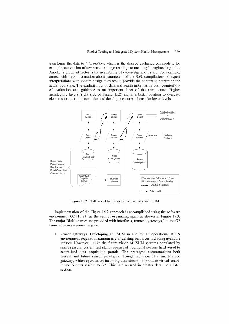
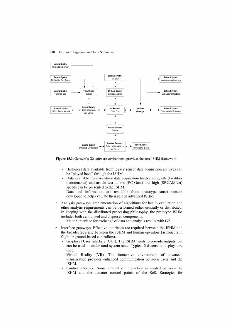
Implementation of the Figure 15.2 approach is accomplished using the software environment G2 [15.23] as the central organizing agent as shown in Figure 15.3. The major DIaK sources are provided with interfaces, termed “gateways,” to the G2 knowledge management engine:
• Sensor gateways. Developing an ISHM in and for an operational RETS
environment requires maximum use of existing resources including available sensors. However, unlike the future vision of ISHM systems populated by smart sensors, current test stands consist of traditional sensors hard-wired to centralized data acquisition portals. The prototype accommodates both present and future sensor paradigms through inclusion of a smart-sensor gateway, which operates on incoming data streams to produce virtual smart-sensor outputs visible to G2. This is discussed in greater detail in a later section.
380 Fernando Figueroa and John Schmalzel
G2 ProcessISHM Core
MATLAB GatewayComplex Analysis
Sensor GatewayData, Information
and Control
Interface GatewaysEnhanced Visualization
and Control
External SystemHealth Anomaly Database
External SystemData Logging Database
External SystemDocumentation Database
External SystemImmersive Environments
Visualization and Control
External SystemPC-Goal Data Stream
External SystemSCRAMNet Data Stream
External System1451.1 Sensor Network
External SystemHistorical Data
Virtual Smart Sensors
External SystemMATLAB
Remote AccessTelewindows & Java
Database Gateways
Figure 15.3. Gensym’s G2 software environment provides the core ISHM framework
- Historical data available from legacy sensor data acquisition archives can be “played back” through the ISHM.
- Data available from real-time data acquisition feeds during idle (facilities maintenance) and article test at low (PC-Goal) and high (SRCAMNet) speeds can be presented to the ISHM.
- Data and information are available from prototype smart sensors developed to help evaluate their role in advanced ISHM.
• Analysis gateways. Implementation of algorithms for health evaluation and other analytic requirements can be performed either centrally or distributed. In keeping with the distributed processing philosophy, the prototype ISHM includes both centralized and dispersed components. - Matlab interface for exchange of data and analysis results with G2.
• Interface gateways. Effective interfaces are required between the ISHM and the broader SoS and between the ISHM and human operators (astronauts in flight or ground-based controllers). - Graphical User Interface (GUI). The ISHM needs to provide outputs that
can be used to understand system state. Typical 2-d console displays are used.
- Virtual Reality (VR). The immersive environment of advanced visualization provides enhanced communication between users and the ISHM.
- Control interface. Some amount of interaction is needed between the ISHM and the actuator control points of the SoS. Strategies for
Rocket Testing and Integrated System Health Management 381
determining how to respond to state assessment must consider available response time. When there is too little time for human-in-the-loop evaluation, the ISHM will need to take action.
• Database gateways. ISHM requires access to an appropriate universe of knowledge encapsulated in a variety of databases. - Health anomaly database. Developing and distributing anomaly detection
is facilitated with a database that includes anomalies (names), exemplar data, and detection algorithms. This can be used to distribute health algorithms and can serve as the source of training data sets.
- Data logging. Historical data records are available through a database. - Documentation database. Access to SoS design documentation is made
available through database access.
15.3.3 Object Framework
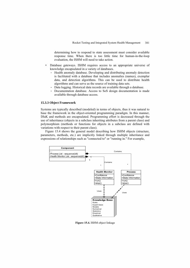
Systems are typically described (modeled) in terms of objects, thus it was natural to base the framework in the object-oriented programming paradigm. In this manner, DIaK and methods are encapsulated. Programming effort is decreased through the use of inheritance (objects in a subclass inheriting attributes from a parent class) and polymorphism (methods or functions for objects in a subclass are defined with variations with respect to their parent class).
Figure 15.4 shows the general model describing how ISHM objects (structure, parameters, methods, etc.) are implicitly linked through multiple inheritance and expressions of relationships such as "connected to" or "running in." For example,
-...-Process List : sequence(idl)-Health Monitor List : sequence(idl)
Component
+run()+stop()
+Confidence+State Information
Process
+run()+stop()
+Confidence+State Information
Health Monitor
1
*
1
*
Knowledge BaseRulesExpert-baseModelsNumericalStatisticsEmpiricalQualitative
UsesUses
Contains
Contains
Figure 15.4. ISHM object linkage
382 Fernando Figueroa and John Schmalzel
tank_pressurization_process running in tank, LOX1.
Objects are also suited to encapsulate rule-based reasoning. For example, it is possible to define a rule that uses a qualitative process describing a step change in the tank parameters as follows:
If the behavior of a temperature-sensor connected to tank LOX1 is step-change-up then the behavior of any pressure-sensor connected to tank LOX1 is step-change-up.
The rule refers to three objects: a temperature sensor, pressure sensor, and a tank. The relationship between the temperature and pressure measurements is inferred from a process that is taking place in the tank, LOX1.
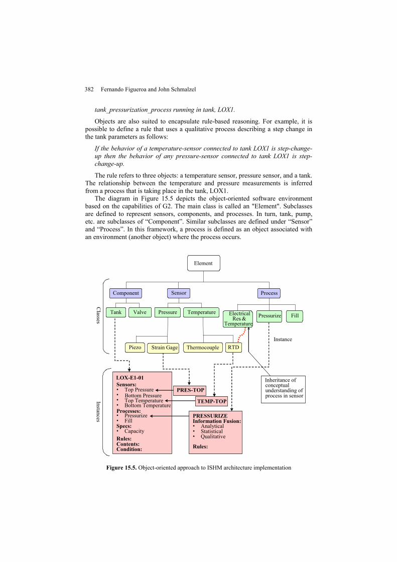
The diagram in Figure 15.5 depicts the object-oriented software environment based on the capabilities of G2. The main class is called an "Element". Subclasses are defined to represent sensors, components, and processes. In turn, tank, pump, etc. are subclasses of “Component”. Similar subclasses are defined under “Sensor” and “Process”. In this framework, a process is defined as an object associated with an environment (another object) where the process occurs.
Element
Sensor Component Process
Tank Valve Pressure Temperature
Thermocouple RTD
Classes
Pressurize Fill
Condition:
Instances
Piezo
PRESSURIZEInformation Fusion:• Analytical• Statistical• Qualitative
Rules:
Electrical Res. &
Temperature
Inheritance of conceptual understanding of process in sensor
Instance Strain Gage
Sensors: • • Bottom Pressure • Top Temperature • Bottom TemperatureProcesses: • Pressurize • Fill Specs: • Capacity Rules: Contents:
LOX-E1-01
Top Pressure PRES-TOP
TEMP-TOP
Figure 15.5. Object-oriented approach to ISHM architecture implementation
Rocket Testing and Integrated System Health Management 383
This overall approach also provides a basis to implement learning. For example, a tank_fill_process object defines a process model for filling tanks, thus it is a process associated with the object tank. Other processes may be tank_pressurization_process, or tank_flow_process. A pipe object will have an associated pipe_flow_process object. A sub-class of this object describing laminar flow may be pipe_flow_process_laminar object. Processes that take place in sensors, but not exclusively, may also be defined under the general Process Class. For example, processes associated with the behavior of electrical resistance and temperature provide a conceptual background to reason about sensors based in the underlying principle of operation (e.g. strain gages, RTDs). In all cases, the basic framework can be updated with progressively finer models as experience is gained with the overall system.
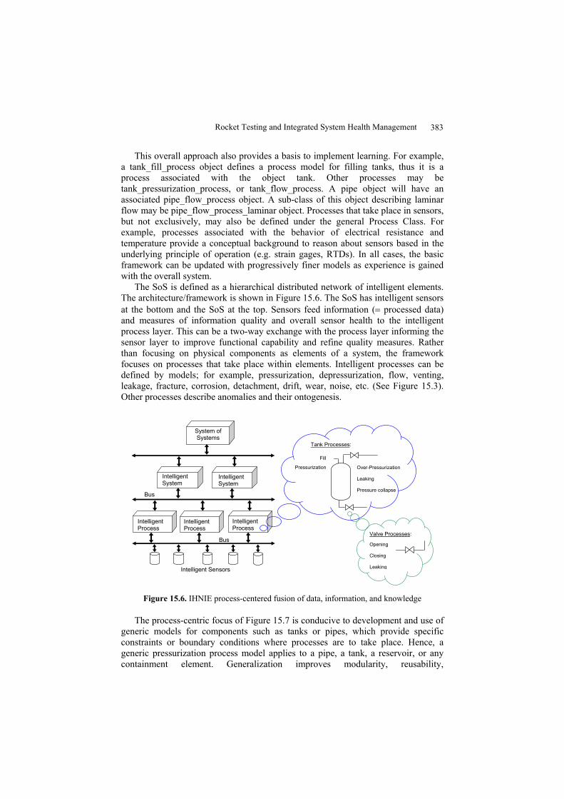
The SoS is defined as a hierarchical distributed network of intelligent elements. The architecture/framework is shown in Figure 15.6. The SoS has intelligent sensors at the bottom and the SoS at the top. Sensors feed information (= processed data) and measures of information quality and overall sensor health to the intelligent process layer. This can be a two-way exchange with the process layer informing the sensor layer to improve functional capability and refine quality measures. Rather than focusing on physical components as elements of a system, the framework focuses on processes that take place within elements. Intelligent processes can be defined by models; for example, pressurization, depressurization, flow, venting, leakage, fracture, corrosion, detachment, drift, wear, noise, etc. (See Figure 15.3). Other processes describe anomalies and their ontogenesis.
Valve Processes: Opening Closing Leaking
Fill
Pressurization Over-Pressurization Leaking Pressure collapse
Tank Processes:
Bus
Intelligent Sensors
Bus
System of Systems
Intelligent Process
Intelligent System
Intelligent System
Intelligent Process
Intelligent Process
Figure 15.6. IHNIE process-centered fusion of data, information, and knowledge
The process-centric focus of Figure 15.7 is conducive to development and use of generic models for components such as tanks or pipes, which provide specific constraints or boundary conditions where processes are to take place. Hence, a generic pressurization process model applies to a pipe, a tank, a reservoir, or any containment element. Generalization improves modularity, reusability,
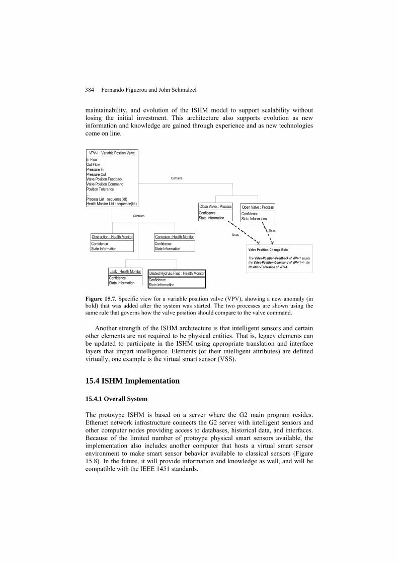
384 Fernando Figueroa and John Schmalzel
maintainability, and evolution of the ISHM model to support scalability without losing the initial investment. This architecture also supports evolution as new information and knowledge are gained through experience and as new technologies come on line.
ConfidenceState Information
Open Valve : ProcessConfidenceState Information
Close Valve : Process
ConfidenceState Information
Corrosion : Health Monitor
ConfidenceState Information
Leak : Health Monitor
ConfidenceState Information
Obstruction : Health Monitor
ConfidenceState Information
Diluted Hydrulic Fluid : Health Monitor
Valve Position Change Rule
The Valve-Position-Feedback of VPV-1 equals the Valve-Position-Command of VPV-1 +/- the Position-Tolerance of VPV-1.
In FlowOut FlowPressure InPressure OutValve Position FeedbackValve Position CommandPosition Tolerance...Process List : sequence(idl)Health Monitor List : sequence(idl)
VPV-1 : Variable Position Valve
UsesUses
Contains
Contains
Figure 15.7. Specific view for a variable position valve (VPV), showing a new anomaly (in bold) that was added after the system was started. The two processes are shown using the same rule that governs how the valve position should compare to the valve command.
Another strength of the ISHM architecture is that intelligent sensors and certain other elements are not required to be physical entities. That is, legacy elements can be updated to participate in the ISHM using appropriate translation and interface layers that impart intelligence. Elements (or their intelligent attributes) are defined virtually; one example is the virtual smart sensor (VSS).
15.4 ISHM Implementation
15.4.1 Overall System
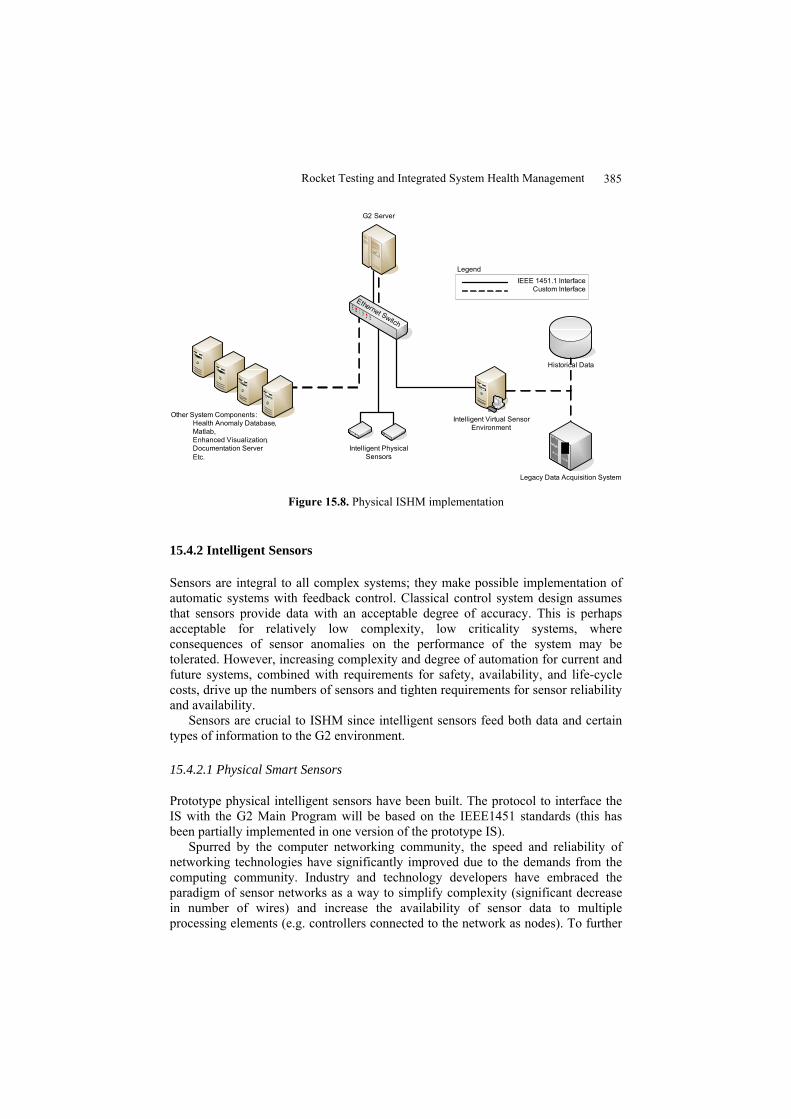
The prototype ISHM is based on a server where the G2 main program resides. Ethernet network infrastructure connects the G2 server with intelligent sensors and other computer nodes providing access to databases, historical data, and interfaces. Because of the limited number of protoype physical smart sensors available, the implementation also includes another computer that hosts a virtual smart sensor environment to make smart sensor behavior available to classical sensors (Figure 15.8). In the future, it will provide information and knowledge as well, and will be compatible with the IEEE 1451 standards.
Rocket Testing and Integrated System Health Management 385
Historical Data
Other System Components:Health Anomaly Database,Matlab,Enhanced Visualization, Documentation ServerEtc.
Ethernet Switch
G2 Server
Intelligent Virtual SensorEnvironment
Intelligent Physical Sensors
IEEE 1451.1 InterfaceCustom Interface
Legend
Legacy Data Acquisition System
Figure 15.8. Physical ISHM implementation
15.4.2 Intelligent Sensors
Sensors are integral to all complex systems; they make possible implementation of automatic systems with feedback control. Classical control system design assumes that sensors provide data with an acceptable degree of accuracy. This is perhaps acceptable for relatively low complexity, low criticality systems, where consequences of sensor anomalies on the performance of the system may be tolerated. However, increasing complexity and degree of automation for current and future systems, combined with requirements for safety, availability, and life-cycle costs, drive up the numbers of sensors and tighten requirements for sensor reliability and availability.
Sensors are crucial to ISHM since intelligent sensors feed both data and certain types of information to the G2 environment.
15.4.2.1 Physical Smart Sensors
Prototype physical intelligent sensors have been built. The protocol to interface the IS with the G2 Main Program will be based on the IEEE1451 standards (this has been partially implemented in one version of the prototype IS).
Spurred by the computer networking community, the speed and reliability of networking technologies have significantly improved due to the demands from the computing community. Industry and technology developers have embraced the paradigm of sensor networks as a way to simplify complexity (significant decrease in number of wires) and increase the availability of sensor data to multiple processing elements (e.g. controllers connected to the network as nodes). To further
386 Fernando Figueroa and John Schmalzel
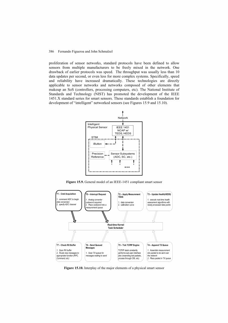
proliferation of sensor networks, standard protocols have been defined to allow sensors from multiple manufacturers to be freely mixed in the network. One drawback of earlier protocols was speed. The throughput was usually less than 10 data updates per second, or even less for more complex systems. Specifically, speed and reliability have increased dramatically. These technologies are directly applicable to sensor networks and networks composed of other elements that makeup an SoS (controllers, processing computers, etc). The National Institute of Standards and Technology (NIST) has promoted the development of the IEEE 1451.X standard series for smart sensors. These standards establish a foundation for development of “intelligent” networked sensors (see Figures 15.9 and 15.10).
Sensor Subsystems(ADC, SC, etc.)
PrecisionReference
iButton
IEEE 1451NCAP w/
TEDS, HEDSSTIM
IntelligentPhysical Sensor
...
Network
Figure 15.9. General model of an IEEE-1451 compliant smart sensor
Real-time Kernel Task Scheduler
T0 – Interrupt Request
1. Analog converter codeword acquired2. Place codeword into a measurement queue
T1 – Cmd Acquisition
1. command ADC to begin data conversion2. specify ADC channel
T4 – Append TX Queue
1. Assemble measurement into packet to be sent over the network2. Place packet in TX queue
T3 – Update Health (HEDS)
1. execute real-time health assessment algorithms with newly processed data points
T2 – Apply Measurement TEDS
1. data conversion2. calibration curve
T5 – Tick TCP/IP Engine
TCP/IP stack constantly performs sub-user interface jobs (resending lost packets , process through OSI, etc)
T6 – Send Queued Messages
1. Scan TX queue for messages waiting to send
T7 – Check RX Buffer
1. Scan RX buffer2. Route new messages to appropriate function (RPC, Command, etc)
Figure 15.10. Interplay of the major elements of a physical smart sensor
Rocket Testing and Integrated System Health Management 387
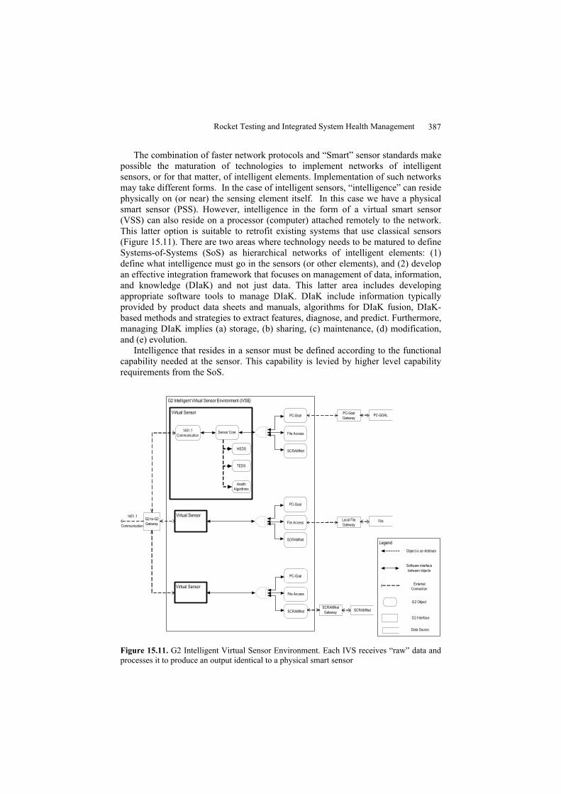
The combination of faster network protocols and “Smart” sensor standards make possible the maturation of technologies to implement networks of intelligent sensors, or for that matter, of intelligent elements. Implementation of such networks may take different forms. In the case of intelligent sensors, “intelligence” can reside physically on (or near) the sensing element itself. In this case we have a physical smart sensor (PSS). However, intelligence in the form of a virtual smart sensor (VSS) can also reside on a processor (computer) attached remotely to the network. This latter option is suitable to retrofit existing systems that use classical sensors (Figure 15.11). There are two areas where technology needs to be matured to define Systems-of-Systems (SoS) as hierarchical networks of intelligent elements: (1) define what intelligence must go in the sensors (or other elements), and (2) develop an effective integration framework that focuses on management of data, information, and knowledge (DIaK) and not just data. This latter area includes developing appropriate software tools to manage DIaK. DIaK include information typically provided by product data sheets and manuals, algorithms for DIaK fusion, DIaK-based methods and strategies to extract features, diagnose, and predict. Furthermore, managing DIaK implies (a) storage, (b) sharing, (c) maintenance, (d) modification, and (e) evolution.
Intelligence that resides in a sensor must be defined according to the functional capability needed at the sensor. This capability is levied by higher level capability requirements from the SoS.
G2-to-G2Gateway
PC-GOAL
File
SCRAMNet
G2 Intelligent Virtual Sensor Environment (iVSE)
PC-Goal Gateway
Local File Gateway
SCRAMNet Gateway
Virtual Sensor
Sensor Core
HEDS
TEDS
Health Algorithms
1451.1 Communication
Virtual SensorPC-Goal
File Access
SCRAMNet
PC-Goal
File Access
SCRAMNet
PC-Goal
File Access
SCRAMNet
Virtual Sensor
Object is an Attribute
Software interface between objects
External Connection
Data Source
G2 Interface
G2 Object
Legend
1451 .1
Communication
Figure 15.11. G2 Intelligent Virtual Sensor Environment. Each IVS receives “raw” data and processes it to produce an output identical to a physical smart sensor
388 Fernando Figueroa and John Schmalzel
To define intelligence resident in an intelligent sensor calls for sensors to provide data, qualification of the condition of the data (e.g. error estimate, useful or not), and the health of the sensor. This package of DIaK must be provided to the process (measurand) with which the sensor is associated (e.g. a pressure sensor measuring a pressurization process in a tank). In turn, the process should provide back to the sensor, information that may be used to update the sensor health. DIaK within each intelligent sensor should be sufficient so that it may use its own historical data, information about the sensor, knowledge of the physical phenomena (empirical, analytical, etc.) governing the operation of the sensor, and perhaps very basic information about the process that the sensor is serving (e.g. an estimate of the time-constant of the parameter being measured), in order to continuously assess its health and the quality of the data. In addition, measurements about the operating environment of the sensor (e.g. temperature, humidity) should also be used as they can help determine the sensor health.
15.4.3 Process Models
Process models may be analytic, qualitative, numerical, etc. It is expected that most models will be in the form of programs in C or C++ Language. Many algorithms (representing process models) to detect anomalies have been adapted to be run from the G2 VS program, the G2 Main Program, and from within PIS. For example, a pressurization process has been defined as a class object. A subclass is pressurization of gasses. An instance of that process object (pressurization of gasses) is defined as a rule:
For any temperature sensor and any pressure sensor attached to a tank, the slope of the temperature sensor has the same sign as the slope of the pressure sensor.
There can be many types of models describing a pressurization process in gasses, and the architecture/taxonomy/ontology is defined to use all relevant models (or model-less) algorithms.
15.5 Implementation/Validation: Rocket Engine Test Stand
The prototype IHNIE is validated by implementing an ISHM system for the Hydraulic Subsystem of a Rocket Engine Test Facility at SSC. A model representing the hydraulic system is being created in the G2 Main Program. Instances of intelligent elements representing legacy elements in the hydraulic system are being defined. Models of virtual intelligent sensors representing legacy sensors in the hydraulic system are being instantiated in the G2 Virtual Intelligent Sensor environment. The implementation uses historical and real-time data to test and validate ISHM capability. The final objective is to insert an ISHM computer/monitor in the Test Control Room to expose operators to ISHM technology capabilities and enlist their help to fine tune and evolve the ISHM system. When physical intelligent sensor prototypes become available for installation in the test stands (two laboratory
Rocket Testing and Integrated System Health Management 389
prototypes with communications capabilities are now available), they will be fully integrated into the ISHM system.
15.6 Conclusions and Future Work
The prototype core elements will also be used to implement ISHM for a subsystem of the International Space Station (ISS). The ISHM Testbeds & Prototypes (ITP) project expands the use of the ISHM technology development resources (data, models, standard interfaces, etc.) and is based on the IHNIE core system. In effect the IHNIE is now a client to the ITP ISS Testbed.
The ITP project is a multi-center NASA effort. Key components include (1) development of advanced smart sensors (KSC), (2) application of the ISHM to a portable, low-thrust rocket engine test skid (SSC), (3) interface to advanced model-based reasoners (ARC), (4) interface to ISS (JSC), and (5) incorporation of advanced health-detection algorithms (GRC, JPL, MSFC, and others).
Acknowledgments
This work has been supported by NASA: Exploration Systems Mission Directorate (Human and Robotic Technology Program) Project “ISHM Testbeds and Prototypes”, Space Operations Mission Directorate (IR&D Program) Project “Intelligent Integrated Health Management System”. The technical support of the entire project team is gratefully acknowledged.
Acronyms
AHM Airplane Health Management ARC Ames Research Center CEV Crew Exploration Vehicle CSIRO Commonwealth Scientific and Industrial Research Organization DIaK Data, Information, and Knowledge GUI Graphical User Interface GRC Glenn Research Center IHNIE Integrated Health with Networked Intelligent Elements ISHM Integrated System Health Management ISS International Space Station ITP ISHM Testbeds & Prototypes IVHM Integrated Vehicle Health Management JPL Jet Propulsion Lab JSC Johnson Space Center KSC Kennedy Space Center MSFC Marshall Space Flight Center NIST National Institute of Standards and Technology PITEX Propulsion IVHM Technology Experiment PSS Physical Smart Sensor RETS Rocket Engine Test Stand
390 Fernando Figueroa and John Schmalzel
RTD Resistance Temperature Device SoS System of Systems SSC Stennis Space Center SSME Space Shuttle Main Engine VR Virtual Reality VSS Virtual Smart Sensor
References
[15.1] http:// www.exploration.nasa.gov. [15.2] Aaseng, G. B., 2001, “Blueprint for an Integrated Vehicle Health Management
System,” Proceedings of 20th Conference on Digital Avionics Systems, pp. 3C1/1-3C1/11.
[15.3] Figueroa, F. and Mahajan, A., 1993, “Generic Model of an Autonomous Sensor,” Proceedings of the ASME Dynamic Systems and Control Division, 50, pp. 183-191.
[15.4] Koushanfar, F., Potkonjak, M. and Sangiovanni-Vincentelli, A., 2003, “On-line Fault Detection of Sensor Measurements,” Proceedings of the IEEE Sensors Conference, 2, pp. 974-979.
[15.5] Biel, L. and Wide, P., 2002, “An Intelligent Model Approach for Combination of Sensor Information,” Proceedings of the IEEE International Workshop on Haptic Virtual Environments and Their Applications, pp. 43-48.
[15.6] Huadong, W., Siegel, M., Stiefelhagen, R. and Jie, Y., 2002, “Sensor Fusion Using Dempster-Shafer Theory [for Context-aware HCI],” Proceedings of the 19th Instrumentation and Measurement Technology Conference, 1, pp. 7-12.
[15.7] Muldoon, S. E., Kowalczyk, M. and Shen, J., 2002, “Vehicle Fault Diagnostics Using a Sensor Fusion Approach,” Proceedings of the IEEE Sensors Conference, 2, pp. 1591-1596.
[15.8] Oza, N. C., Polikar, R., Kittler, J. and Roli, F., Eds., 2005, Proceedings of the 6th International Workshop on Multiple Classifier Systems.
[15.9] http://www.aviationweek.com/shownews/03paris/topstor3_16.htm. [15.10] Ramohalli, G., 1994, “Honeywell’s Aircraft Monitoring and Diagnostic Systems for
the Boeing 777,” Proceedings of the 17th Symposium on Aircraft Integrated Monitoring Systems, pp. 69-71, 73-87.
[15.11] Zuniga, F. A., Maclise, D. C., Romano, D. J., Jize, N. N., Wysocki, P. F. and Lawrence, D. P., 2005, “Integrated Systems Health Management for Exploration Systems,” Proceedings 1st Space Exploration Conference: Continuing the Voyage of Discovery, AIAA 2005-2586.
[15.12] Davidson, M. and Stephens, J., 2004, “Advanced Health Management System for the Space Shuttle Main Engine,” Proceedings 40th AIEE/ASME/SAE/ASEE Joint Propulsion Conference and Exhibit, AIAA 2004-3912.
[15.13] http://www.nasa.gov/pdf/1975main_shuttle.pdf. [15.14] Jue, F. and Kuck, F., 2002, “Space Shuttle Main Engine (SSME) Options for the
Future Shuttle,” Proceedings 38th AIEE/ASME/SAE/ASEE Joint Propulsion Conference and Exhibit, AIAA 2002-3758.
[15.15] Schweikhard, K. A., Theisen, J., Mouyos, W. and Garbo, R., 2001, “Flight Demonstration of X-33 Vehicle Health Management System Components on the F/A-18 Systems Research Aircraft,” NASA/TM-2001-209037.
[15.16] Bajwa, A. and Sweet, A., 2002, “The Livingstone Model of a Main Propulsion System,” RIACS Technical Report 03.04. Available at http://www.riacs.edu/trs/.
[15.17] Prosser, W. H., Allison, S. G., Woodard, S. E., Wincheski, R. A., Cooper, E. G.,
Rocket Testing and Integrated System Health Management 391
Price, D. C., Hedley, M., Prokopenko, M., Scott, D. A., Tessler, A. and Spangler, J. L., 2004, “Structural Health Management for Future Aerospace Vehicles,” Proceedings of the 2nd Australian Workshop on Structural Health Management.
[15.18] Hammett, R. C., 2001, “Networking Intelligent Components to Create Intelligent Spacecraft,” Proceedings of the IEEE Aerospace Conference, 5, pp. 2209-2215.
[15.19] http://grouper.ieee.org/groups/1451/0/. [15.20] Lee, K., 2001, “Sensor Networking and Interface Standardization,” Proceedings of
the 18th IEEE Conference on Instrumentation and Measurement Technology, pp. 147-152.
[15.21] Liu, S. C., Tomizuka, M. and Shoureshi, R., 2003, “Strategic Research for Sensors and Smart Structures Technology,” Proceedings of 1st International Conference on Structural Health Monitoring and Intelligent Infrastructure.
[15.22] Schmalzel, J., Figueroa, F., Morris, J., Mandayam, S. and Polikar, R., 2004, “An Architecture for Intelligent Systems Based on Smart Sensors,” Proceedings of the 21st IEEE Conference on Instrumentation and Measurement Technology, pp. 71-75.
[15.23] http://www.gensym.com. [15.24] http://www.systranfederal.com.