Embed Size (px)
Citation preview
P a g e | 64 Engineering Design Criteria & Standard Drawings (December 2020)
1.5 Water Distribution System 1.5.1 General
The water distribution system is to be designed as a network system to meet the water demand for the development lands under consideration as well as the surrounding area, with proper looping and system security. Long dead end mains and single supply systems are to be avoided and looping is encouraged. The system shall be designed to service all areas within the subdivision to their maximum future development in accordance with the Official Plan and the City-Wide Water & Wastewater Master Plan. Allowance shall be made for external lands within the pressure district boundaries as established by the City and Region of York. Allowance shall be made for connection to appropriate mains to the approval of the City and Region of York.
1.5.2 Water Demand
1.5.2.1 Calculations The water demand used for main size selection should be equal to the Fire Flow Demand plus the Maximum Day Demand or the Peak Hour Demand, whichever is greater. The average daily demands to be used for analysis purposes are as follows:
• For service areas in Pressure Districts PD4, PD5, PD6, PD7, PD8 and PD9 o Residential & Employment): 300 Lpcd
• For service areas in PD-KN (Kleinburg-Nashville): o Residential 347 Lpcd o Employment 317 Lpcd
Population estimates shall generally be based on the densities provided in Table 1-15 wherever sufficiently detailed information is available, otherwise estimates shall be in compliance with the City’s Official Plan, the relevant Secondary Plan, Block Plan or other appropriate planning document. The maximum day demand factors to be applied are as follows:
• For service areas in PD4, PD5, PD6, PD7, PD8 and PD9 (residential & employment): 1.8 • For service areas in PD-KN (residential & employment): 2.5
The peak hour demand factors to be applied are as follows:
• For service areas in PD4, PD5, PD6, PD7, PD8 and PD9 (residential & employment): 3.0 • For service areas in PD-KN (residential & employment): 4.0
Refer to Figure 1-5 for Pressure District map of City. Other peak flows shall be determined on an individual basis, as appropriate.

P a g e | 65 Engineering Design Criteria & Standard Drawings (December 2020)
Figure 1-5 Pressure District Map (Source: City-Wide Water & Wastewater Master Plan)
Pressure District Legend for Figure General Ground Elevation Limits (m)
PD4 143-174
PD5 163-195
PD6 195-229
PD7 227-256
PD8 256-282
PD9 282-315
PD-KN 195-240
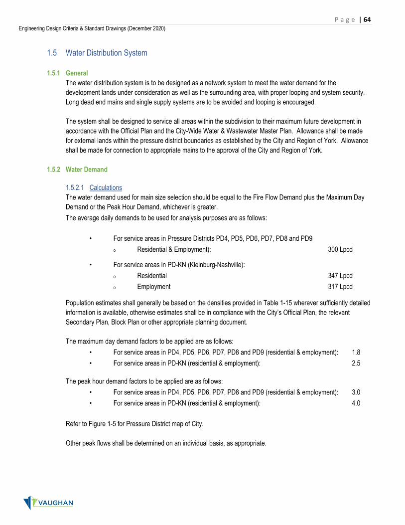
Fire flow demands shall generally be in accordance with Table 1-18 and shall not be less than those calculated according to the latest published requirements of the Water Supply for Public Fire Protection, Fire Underwriters Survey.
P a g e | 66 Engineering Design Criteria & Standard Drawings (December 2020)
Table 1-18 Fire Flow Demand Land Use Fire Flow
Single Family & Semi-Detached 7,000 L/min or 117 L/s
Townhouses 9,000 L/min or 150 L/s
Institutional 15,000 L/min or 250 L/s
Industrial/Commercial 25,000 L/min or 417 L/s
Multi-Unit Apartment Buildings 19,000 L/min or 317 L/s
1.5.3 Selection of Main Sizes
1.5.3.1 Formula The Hazen-Williams formula shall be used for computing the size of watermains. 54.063.2 SDC278.0Q ×××= and 54.063.0 SRC85.0V ×××= where Q is the flow in the pipe (m3/s) V is the velocity in the pipe (m/s) C is the Hazen-Williams coefficient (dimensionless)
D is the internal pipe diameter (m) R is the hydraulic radius of the pipe (i.e., cross-sectional area ÷ wetted perimeter; m) S is the slope of the hydraulic grade line (m/m) The Hazen-William “C” values to be used in any analysis, regardless of pipe material, are listed in Table 1-19.
Table 1-19 Hazen-Williams “C” Values Diameter of Main “C” Value
150 mm 100
200 mm & 250 mm 110
300 mm to 600 mm 120
Larger than 600 mm 130
1.5.3.2 Minimum Sizes and Water Pressure Requirements The minimum size of mains shall be 150 mm diameter in residential areas and 300mm diameter in industrial areas. The minimum pressure during the maximum hourly demand under static condition shall be 275 kPa (40 psi). The minimum pressure when the system is tested for fire flow demand, plus maximum day rate or maximum hour rate whichever greater shall be 140 kPa (20 psi). The maximum pressure under static condition or during the minimum hourly demand shall be 690 kPa (100 psi).

P a g e | 67 Engineering Design Criteria & Standard Drawings (December 2020)
1.5.3.3 Water Supply Analysis A Water Supply Analysis Report shall be submitted to the satisfaction of the City. It shall include a hydraulic network analysis (preferably using H2ONET/InfoWater modelling software) of the water distribution system and shall be carried out as required to demonstrate that adequate water supply is available to service the proposed development. The report is to identify the need and timing of system improvements, and to demonstrate that the proposed system will not adversely affect the surrounding system in terms of pressure and supply. The hydraulic analysis shall include allowances for demands of adjacent areas anticipated to be met by transmission through the design area. Hydrant flow tests in accordance with NFPA 291 are required to support boundary condition assumptions used in the hydraulic analysis
1.5.3.4 Service Connections & Metering
1.5.3.4 (a) Residential
Single connections shall be a minimum of 25 mm in diameter together with a 25 mm diameter curb stop 0.1m from the street line per Standard Drawing C-101. Diameters of service connections may be increased to compensate for lower pressures in areas of minimum pressures (e.g., at boundaries of water pressure districts) or under the following conditions:
• very high demands are anticipated; • where house is equipped with a fire suppressing sprinkler system; • where static water pressure under peak hour demand periods is expected to be 310 kPa
or less; • where water service connections are 30 metres or greater in length (measured from
watermain to the building envelope); • where lot sizes are 500 m2 or larger; or • where house elevations are significantly higher than road elevations.
Where these areas of minimum pressures cannot be compensated for with increased service connection diameter, individual booster pumps may be provided for each building as required, to provide the required pressures, so long as the fire flow requirements (pressure and flow demand) are provided for in the watermain sizing. Saddles are required for service connection sizes larger than 25 mm and up to 50 mm in diameter.

P a g e | 68 Engineering Design Criteria & Standard Drawings (December 2020)
1.5.3.4 (b) Industrial Commercial Institutional, Multi Unit Apartment and Condominium Site
• Service Connections shall meet our design standards and include fire and domestic lines.
• Water service diameter for fire lines shall be 150mm and for domestic lines 50mm. Size and number of water service connections may increase subject to the Ontario Building Code requirements.
Diameters of service connections may be increased similar to section 1.5.3.4 (a). Where these areas of minimum pressures cannot be compensated for with increased service connection diameter, individual booster pumps may be provided for each building as required, to provide the required pressures, so long as the fire flow requirements (pressure and flow demand) are provided for in the water sizing.
1.5.3.4 (c) Backflow Prevention and Metering
All service connections from the City’s water system for the following uses must be metered and include backflow prevention devices in accordance with the relevant standard drawings: • Industrial, Commercial, Institutional, Multi-Unit Apartment and Condominium Sites • Irrigation systems on publicly owned lands (e.g., parks, boulevards, etc.)
o Meters for park and boulevard irrigation (i.e., turf valves) to be installed in accordance with City requirements.
P a g e | 69 Engineering Design Criteria & Standard Drawings (December 2020)
There shall be 1 meter for each municipal address. Water meters will be supplied and installed by the City at the owner’s cost.
1.5.3.5 Oversizing
Oversizing of watermains will be provided for adjacent areas where service is expected to be extended, and to provide fire flow requirements where serviced areas are extended beyond water district boundaries.
1.5.4 Layout Details
1.5.4.1 Mains
1.5.4.1 (a) LOCATION – Watermains shall be located within the boulevard area as shown in the road cross-sections contained in the City’s Standard Drawings.
1.5.4.1 (b) DEPTH – A minimum cover of 2.0 metres or 2.1 metres below road centre line, whichever is deeper.
1.5.4.1 (c) CLEARANCE – Minimum horizontal and vertical clearances between municipal services shall be provided in accordance with the latest MECP guidelines.
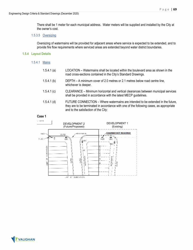
1.5.4.1 (d) FUTURE CONNECTION – Where watermains are intended to be extended in the future, they are to be terminated in accordance with one of the following cases, as appropriate and to the satisfaction of the City:
Case 1

P a g e | 70 Engineering Design Criteria & Standard Drawings (December 2020)
Case 2
Case 3

P a g e | 71 Engineering Design Criteria & Standard Drawings (December 2020)
1.5.4.2 Hydrants
1.5.4.2 (a) (i) LOCATION – Hydrants shall be located as follows:
1.5.4.2 (a) (ii) generally on lot lines in residential developments and in the middle of the lot/block in industrial/commercial/institutional and multi-unit apartment building developments;
1.5.4.2 (a) (iii) within the road allowance according to the road cross-sections detailed in the City’s Standard Drawings;
1.5.4.2 (a) (iv) minimum 1.0 metre clearance from the edge of driveways, walkways, house service connections and other above ground utilities;
1.5.4.2 (a) (v) at the end of all dead end watermains; and
1.5.4.2 (a) (vi) at high points in the watermain.
1.5.4.2 (b) SPACING
1.5.4.2 (b) (i) NEW DEVELOPMENT – The maximum spacing between two hydrants shall be 90 for residential, industrial, commercial and institutional development areas and/or to the satisfaction of the City.
1.5.4.2 (b) (ii) RE-DEVELOPMENT AREAS – Existing hydrant spacing to be reviewed and new hydrants to be installed to ensure that a maximum spacing of 90 m is provided.
1.5.4.3 Valves
1.5.4.3 (a) LOCATION – Valves shall be located generally on side lot/block lines, at intersections, and as required for spacing.
1.5.4.3 (b) INTERSECTIONS – Generally 3 valves shall be placed at cross-intersections and 2 valves at "T" intersections, such that broken sections can be isolated without jeopardizing flow to other sections. An additional valve may be required for operational reasons.
1.5.4.3 (c) SPACING – Valves shall be spaced so that a maximum of 40 dwelling units are isolated along a watermain and at a maximum spacing of 240 metres for distribution watermains and 400 metres for trunk supply watermains.
1.5.4.3 (d) AIR VALVES – Air valves shall be considered where high points cannot be eliminated by watermain alignment and where a hydrant is impractical.
1.5.4.3 (e) DRAIN VALVES – Drains shall be considered at low points of watermains and where possible, installed within valve chambers. Where possible, all drains shall have outlets to a storm sewer system or other suitable outlet.
1.5.4.3 (f) VALVE BOXES & CHAMBERS – Valve boxes are acceptable for line valves up to and including 300 mm diameter watermains. Valves located at roadway intersections shall be in chambers for all valve sizes. Multi-valve chambers are acceptable, subject to City approval.
1.5.4.4 Service Connections
1.5.4.4 (a) LOCATION – Water service connections for residential development shall be in accordance with Standard Drawing C-101 and preferred location will be in a grassed
P a g e | 72 Engineering Design Criteria & Standard Drawings (December 2020)
area. Service connections for industrial/commercial/institutional (ICI) blocks, as well as for park blocks, shall generally be located in the centre of the blocks and in accordance with Standard Drawing C-102. Water services should be at least 2.5 m away from any sewer connections. Connections for industrial/commercial/institutional or multi-unit apartment developments will be considered on an individual basis if similar locations cannot be used. All connection locations must be detailed on Plan and Profile drawing and Lot Grading Plans. Irrigation system shall be installed at major gateway intersections and large planted medians in accordance with City requirements.
1.5.4.4 (b) DEPTH – Service connections shall be located at a minimum depth of 2.0 metres. In cases where this depth cannot be achieved (e.g., crossing over storm sewer), the minimum depth of installation may be reduced to 1.5 metres and the water service must be insulated, subject to maintaining a minimum 0.5 metres clearance to any storm sewer, if applicable.
1.5.4.5 Cathodic Protection Sacrificial anodes shall be installed as follows:
• Metallic mechanical joints/fittings/restraints. Sizing to be determined by geotechnical engineer subject to a minimum of 12 lb each.
• Service connections (i.e., curb stops). Sizing to be determined by geotechnical engineer subject to a minimum of 6 lb each.
• Hydrants shall have 24 lb anodes in accordance with Standard Drawing W-104. • On exposed metallic piping or fittings when connecting to non-metallic pipe and/or when making
repairs to breaks and/or leaks. Sizing to be determined by geotechnical engineer subject to a minimum of 12 lb each.
1.5.5 Materials
1.5.5.1 Standard Watermains
1.5.5.1 (a) SPECIFICATIONS – 150mm and larger diameter watermains, fittings and connections shall be manufactured in accordance with the latest specifications of the American Water Works Association, the Canadian Standards Association or the Canadian Government Specification Board for a minimum 1035 kPa (150 psi) rated working pressure as follows:
1.5.5.1 (b) POLYVINYL CHLORIDE (PVC) PIPE– Watermain pipe shall be polyvinyl chloride (PVC) pipe in accordance with the following specifications:
1.5.5.1 (b) (i) 150 mm – 300 mm diameter: Min. Class 150, CSA B137.3, AWWA C900, Min. DR 18
1.5.5.1 (b) (ii) 400 mm diameter: Min. Class 150, CSA B137.3, AWWA C905, Min. DR 18
Tracer wire (8 gauge) to be installed on all watermains between hydrants, valves or other conduction appurtenances.
1.5.5.1 (c) REINFORCED CONCRETE PIPE (RCP) – Conforming to AWWA C301 and C303 shall be used for trunk water supply watermains, larger than 400 mm in diameter, including factory installed outlets and connections, and approved fittings compatible with ductile iron pipe fittings including tracer wire.
1.5.5.1 (d) JOINTS & BENDS – Joints and fittings shall be as per AWWA C907 specifications. Restraints required as indicated in Standard Drawings.

P a g e | 73 Engineering Design Criteria & Standard Drawings (December 2020)
1.5.5.1 (e) BEDDING AND BACKFILLING – Bedding material to be mortar sand conforming to OPSS 1004 Granular D and placed in accordance with applicable OPS Drawings11. Bedding to extend a minimum of 150 mm or 1/4 of the pipe diameter, whichever is greater, around all sides of the pipe.
1.5.5.1 (f) THRUST BLOCKS – Shall only be used as approved by the City and in accordance with OPSD 1103.010 and OPSD 1103.020.
1.5.5.2 Service Connections and Water Lines
1.5.5.2 (a) SPECIFICATIONS – For service connections and water lines less than 150mm in diameter, fittings and connections shall be manufactured in accordance with the latest specifications of the Ontario Building Code, Canadian Standards Association, and the American Society of Testing and Materials for 1000 kPa rated working pressure as follows:
1.5.5.2 (a) (i) Copper "Type K" tubing and fittings up to and including 50 mm in diameter, and electrochemical corrosion protection where connected to ductile iron watermains.
1.5.5.2 (a) (ii) Polyvinyl chloride pipe and fittings to CSA Standard B137.3, including approved frost protection.
1.5.5.2 (b) JOINTS AND CONNECTIONS – Shall be pressure tested with the watermain system, and shall be in accordance with City Specifications and the Ontario Building Code.
1.5.5.2 (c) SHUT-OFF VALVES – Provided at the street line according to Standard Drawings C-101 to C-103 inclusive.
1.5.5.3 Hydrants Hydrants shall meet the requirements of AWWA Standard C502 and according to Standard Drawing W-104.
Hydrants shall be equipped with anti-tampering devices to the Satisfaction of the City prior to the issuance of building permits and shall be removed prior to assumption of municipal services.
1.5.5.4 Valves
1.5.5.4 (a) SPECIFICATIONS – Valves up to and including 400 mm diameter will be gate valves of the solid wedge, double disc type according to AWWA Standard C500. Valves larger than 400 mm diameter shall be butterfly valves or as specified by the City.
1.5.5.4 (b) CHAMBERS AND BOXES – According to Standard Drawings, including restraints as required in accordance with the Standard Drawings.
1.5.5.5 Tapping Sleeves Tapping sleeves to be stainless steel only, for all pipe materials, constructed entirely of type 304 stainless steel, all welds to be fully passivated by chemical dip method. Maximum tapping size shall one size smaller than the main size for all pipes up to and including 400 mm diameter. Smaller tapping sizes may be required when deemed necessary by the City.
11 Depending on pipe material and installation condition, the following OPS Drawings may apply: OPSD802.010, 802.014, 802.030, 802.031, 802.033, 802.034, 802.050, 802.051, 802.052, 802.053 or 802054

P a g e | 74 Engineering Design Criteria & Standard Drawings (December 2020)
1.5.6 Testing & Inspection All watermains are to be cleaned by foam swabbing, hydrostatically tested, disinfected, flushed and sampled in accordance with the Safe Drinking Water Act and Regulations and the City’s watermain testing requirements and procedures prior to commissioning.
1.5.6.1 Hydrostatic Testing Hydrostatic testing of watermains to conform to AWWA C605 (PVC) and OPSS 441.07.24 procedures in accordance with the following:
• Test pressure: 1,035 kPa (150 psi) • Test duration: 2 hours • Allowable leakage: 0.082 L / mm of nominal pipe diameter / km of test section
1.5.6.2 Hydrant Flow Testing
Prior to acceptance, all hydrants on new watermains are to be flowed and 3-point NFPA 291 hydrant flow tests (i.e., static plus 2 flow rates) are required on selected hydrants to confirm the performance of the water distribution system. The number and location of flow tests will be site-specific and subject to the approval of the City. In general, such tests will be conducted at selected dead end locations, at high points in the system or at parts of the newly installed network of pipes farthest from the points of supply. A licensed Professional Engineer is to certify that the results of the testing conform to the intended design performance of the system.
Hydrant Flow Tests shall be conducted to validate the fire flow requirement to the Satisfaction of the City prior to the issuance of building permits.
1.5.6.3 Tracer Wire
Tracer wire inspections and conductivity tests shall be conducted prior to acceptance. Inspections are to ensure that tracer wire is visible in chambers, on hydrants, valve boxes, etc. Conductivity tests are to ensure that the tracer wire is appropriately connected and continuous over its entire length.
1.5.6.4 Pressure Reducing Valves (PRVs)
The following general requirements must be met when commissioning PRVs:
• Engineer to provide desired PRV setting information to be approved by City. • Pressures on upstream and downstream side to be observed and recorded during
commissioning procedure. • The City may require flow measurements to be taken as part of the commissioning procedure. • Detailed report to be provided to City, signed and stamped by a Professional Engineer describing
commissioning procedure, pressure (and any flow) measurements, and attesting to the appropriate functioning of the device.
• PRV shall be operational to the satisfaction of the City prior to commissioning.
1.5.6.5 City Representation
A representative of the City is required to be present during any testing of services.
P a g e | 75 Engineering Design Criteria & Standard Drawings (December 2020)
1.5.7 Decommissioning 1.5.7.1 Service Connections
Water service connections are to be decommissioned by plugging the watermain service at the main, plugging the watermain service crossing the pavement within both sides of the boulevard, removal of the valve box extensions, filling the entire valve chamber with sand, backfilling and surface restoration.
1.5.7.2 Watermains
The following is required when decommissioning watermains:
• Saw-cutting of existing pipe. • Removal and disposal off-site of existing pipes, fittings, thrust restraints and thrust blocks, as required. • Filling of abandoned main with grout. • Supply and placement of 15 MPa concrete plug in the ends of the existing watermains that are to
be abandoned in place. Minimum length of the concrete plug shall be 300mm. • Supply and placement of mechanical plug on existing watermain to remain in service, where required.
1.5.7.3 Chambers Any openings to valve chambers should be plugged from within the chamber and the upper sections are to be removed and the chamber filled with sand prior to backfilling and restoration of the surface.
1.5.8 Water Pumping Stations
Water pumping stations shall generally be designed in accordance with Ministry of the Environment Conservation and Parks (MECP) and Region of York standards and guidelines.
Stations shall preserve the architectural nature of the community where they are situated and, where applicable, conform to architectural control guidelines. Landscaping is required and subject to the approval of the City.
Permanent and high accuracy, flow meter as well as suction and discharge header pressure sensors to have SCADA capability. Additional requirements may be determined by the City.
1.5.8.1 Commissioning Commissioning testing of water pumping stations is required and shall be certified by a Professional Engineer. Testing to generally include the following, although additional testing may be required by the City:
• Testing of station performance over full range of flows, including transitions between pumps. • In situ testing of pump performance and efficiency for pumps 150 hp and larger. • Continuous high-frequency (min 1 Hz) pressure monitoring during testing procedure and for 24 h period
under normal operations using portable equipment. • Continuous flow monitoring using portable flow meter placed on discharge line during testing procedure
and for 24 h period under normal operations. Reporting to include the following:
• Plots of pressure and flow during testing procedure. • Actual in situ pump performance and efficiency curves/points plotted against pump manufacturer’s
curves. • Comparison of measured flow and pressure data as read by the permanent sensing devices and the
portable testing devices. • Reports to including all relevant interpretation and explanations, including discussion of impact to
operations and life cycle costs.