Embed Size (px)
Citation preview
150 lb. Drywall Panel Hoist
Item 99645
InstructIons anD PrecautIons
Visit our website at: http://www.harborfreight.com
email our technical support at: [email protected]
read this material before using this product.Failure to do so can result in serious injury.saVe tHIs manual.
When unpacking, make sure that the product is intact and undamaged. If any parts are missing or broken, please call 1‑800‑444‑3353 as soon as possible.
Copyright© 2008 by Harbor Freight Tools®. All rights reserved. No portion of this document or any artwork contained herein may be reproduced in any shape or form without the express written consent of Harbor Freight Tools. Diagrams within this document may not be drawn proportionally. Due to continuing improvements, actual product may differ slightly from the product described herein. Tools required for assembly and service may not be included.
For technical questions or replacement parts, please call 1‑800‑444‑3353.
Manual Revised 11f
Page 2 For technical questions, please call 1‑800‑444‑3353. SKU 99645
save this manual
Keep this manual for the safety warnings and precautions, assembly, operating, inspection, maintenance and cleaning procedures. Write the product’s serial number in the back of the manual near the assembly diagram (or month and year of purchase if product has no number). Keep this manual and the receipt in a safe and dry place for future reference.
ImPortant saFetY InFormatIon
In this manual, on the labeling, and all other information provided with this product:
this is the safety alert symbol. It is used to alert you to potential personal injury hazards. obey all safety messages that follow this symbol to avoid possible injury or death.
DanGer indicates a hazardous situation which, if not avoided, will result in death or serious injury.
WarnInG indicates a hazardous situation which, if not avoided, could result in death or serious injury.
cautIon, used with the safety alert symbol, indicates a hazardous situation which, if not avoided, could result in minor or moderate injury.
notIce is used to address practices not related to personal injury.
cautIon, without the safety alert symbol, is used to address practices not related to personal injury.
1. Maintain labels and nameplates on the tool. These carry important safety information. If unreadable or missing, contact Harbor Freight Tools for a replacement.
2. Keep children away. Children must never be allowed in the work area. Do not let them handle machines, tools or let them climb on or play with the product.
3. Store idle equipment. When not in use, tools must be stored in a dry location to inhibit rust. Always lock up tools and keep out of reach of children.
4. Use the right tool for the job. Do not attempt to force a small tool or attachment to do the work of a larger industrial tool. There are certain applications for which this tool was designed. It will do the job better and more safely at the rate for which it was intended.
5. Do not modify this tool and do not use this tool for a purpose for which it was not intended.
6. Dress properly. Do not wear loose clothing or jewelry as they can be caught in moving parts. Protective, electrically nonconductive clothes and nonskid footwear are recommended when working. Wear restrictive hair covering to contain long hair.
7. Wear ANSI‑approved safety goggles, an ANSI‑approved hardhat and heavy‑duty work gloves during set up and use.
Page 3For technical questions, please call 1‑800‑444‑3353.SKU 99645
8. Do not overreach. Keep proper footing and balance at all times. Do not reach over or across a Panel Hoist while in operation. Do not walk or stand under Panel Hoist needlessly while in operation.
9. Maintain tools with care. Keep tools clean for better and safer performance. Follow instructions for lubricating and changing accessories.
10. Stay alert. Watch what you are doing, use common sense. Do not operate any tool when you are tired.
11. Check for damaged parts. Before using any tool, any part that appears damaged should be carefully checked to determine that it will operate properly and perform its intended function. Check for alignment and binding of moving parts; any broken parts or mounting fixtures; and any other condition that may affect proper operation. Any part that is damaged should be properly repaired or replaced by a qualified technician. Do not use the tool if any control does not operate properly.
12. When servicing, use only identical replacement parts. Use of any other parts will void the warranty. Only use accessories intended for use with this tool. Approved accessories are available from Harbor Freight Tools.
13. Do not operate tool if under the influence of alcohol or drugs. Read warning labels if taking prescription medicine to determine if your judgment or reflexes are impaired while taking drugs. If there is any doubt, do not operate the tool.
14. For your safety, service and maintenance should be performed regularly by a qualified technician.
15. Stand clear of the Panel Hoist when raising or lowering a panel. Never reach through the winch wheel.
16. Do not exceed the Hoist’s capacity of 150 lb. Check the manufacturer’s documentation to determine the actual weight of panels before attempting to lift them.
17. Do not ride on the Panel Hoist, and never have people or pets in the area while operating Hoist.
18. Only use the Hoist to raise/lower one drywall panel at a time. After raising the panel, immediately fix in place using the recommended type, number and pattern of nails, adhesive or screws. Do not use this Hoist to store panels.
19. Place Panel Hoist on correct surface. Only use this Hoist on a stable, level, clean, hard and dry surface that is capable of sustaining the load.
20. Stabilize the load. Ensure that the load remains stable at all times. Do not move the load while it is on the Hoist.
21. Center the load on the Panel Hoist. Off‑center loads can topple, causing property damage or injury.
22. Do not lubricate any part of the Winch components. The brake is friction based and may fail if lubricated.
23. Before each use, check that the cable is properly tensioned and wound tightly and evenly onto the spool.
24. Before lifting load to full height, first lift a short distance. Check that the brake is engaged, then continue to lift to full height.
25. The warnings, precautions, and instructions discussed in this instruction manual cannot cover all possible conditions and situations that may occur. It must be understood by the operator that common sense and caution are factors which cannot be built into this product, but must be supplied by the operator.
saVe tHese InstructIons.
Page 4 For technical questions, please call 1‑800‑444‑3353. SKU 99645
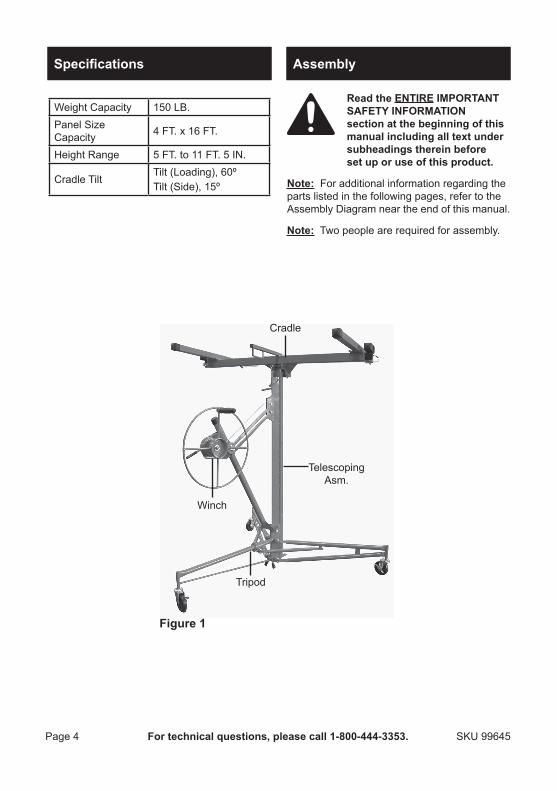
Specifications
Weight Capacity 150 LB.Panel Size Capacity 4 FT. x 16 FT.
Height Range 5 FT. to 11 FT. 5 IN.
Cradle TiltTilt (Loading), 60ºTilt (Side), 15º
assembly
read the entIre ImPortant saFetY InFormatIon section at the beginning of this manual including all text under subheadings therein before set up or use of this product.
note: For additional information regarding the parts listed in the following pages, refer to the Assembly Diagram near the end of this manual.
note: Two people are required for assembly.
Winch
Cradle
Tripod
Telescoping Asm.
Figure 1
Page 5For technical questions, please call 1‑800‑444‑3353.SKU 99645
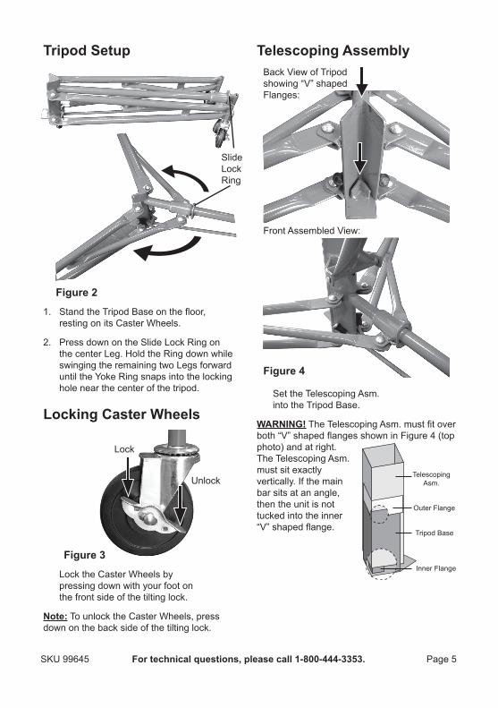
tripod setup
1.
Figure 2
Slide Lock Ring
Stand the Tripod Base on the floor, resting on its Caster Wheels.
2. Press down on the Slide Lock Ring on the center Leg. Hold the Ring down while swinging the remaining two Legs forward until the Yoke Ring snaps into the locking hole near the center of the tripod.
locking caster Wheels
Lock
Unlock
Figure 3
Lock the Caster Wheels by pressing down with your foot on the front side of the tilting lock.
note: To unlock the Caster Wheels, press down on the back side of the tilting lock.
telescoping assembly
Figure 4
Back View of Tripodshowing “V” shaped Flanges:
Front Assembled View:
Set the Telescoping Asm. into the Tripod Base.
WarnInG! The Telescoping Asm. must fit over both “V” shaped flanges shown in Figure 4 (top photo) and at right. The Telescoping Asm. must sit exactly vertically. If the main bar sits at an angle, then the unit is not tucked into the inner “V” shaped flange.
Outer Flange
Inner Flange
Telescoping Asm.
Tripod Base
Page 6 For technical questions, please call 1‑800‑444‑3353. SKU 99645
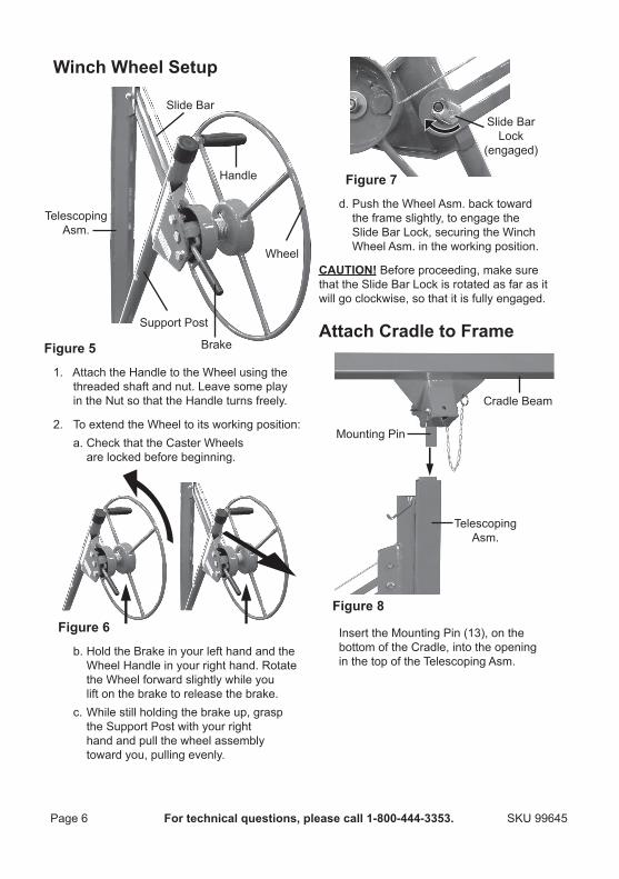
Winch Wheel setup
1.
Support Post
Slide Bar
Telescoping Asm.
Wheel
Handle
BrakeFigure 5
Attach the Handle to the Wheel using the threaded shaft and nut. Leave some play in the Nut so that the Handle turns freely.
2. To extend the Wheel to its working position:a. Check that the Caster Wheels
are locked before beginning.
b.
Figure 6
Hold the Brake in your left hand and the Wheel Handle in your right hand. Rotate the Wheel forward slightly while you lift on the brake to release the brake.
c. While still holding the brake up, grasp the Support Post with your right hand and pull the wheel assembly toward you, pulling evenly.
d.
Slide BarLock
(engaged)
Figure 7
Push the Wheel Asm. back toward the frame slightly, to engage the Slide Bar Lock, securing the Winch Wheel Asm. in the working position.
cautIon! Before proceeding, make sure that the Slide Bar Lock is rotated as far as it will go clockwise, so that it is fully engaged.
attach cradle to Frame
Figure 8
Cradle Beam
Telescoping Asm.
Mounting Pin
Insert the Mounting Pin (13), on the bottom of the Cradle, into the opening in the top of the Telescoping Asm.
Page 7For technical questions, please call 1‑800‑444‑3353.SKU 99645
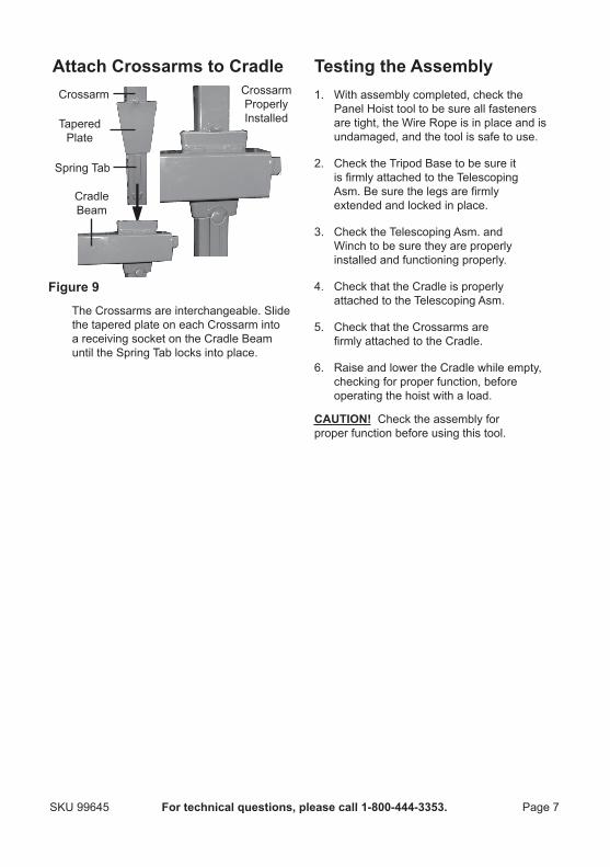
attach crossarms to cradle
Cradle Beam
Crossarm
TaperedPlate
CrossarmProperly Installed
Spring Tab
Figure 9
The Crossarms are interchangeable. Slide the tapered plate on each Crossarm into a receiving socket on the Cradle Beam until the Spring Tab locks into place.
testing the assembly1. With assembly completed, check the
Panel Hoist tool to be sure all fasteners are tight, the Wire Rope is in place and is undamaged, and the tool is safe to use.
2. Check the Tripod Base to be sure it is firmly attached to the Telescoping Asm. Be sure the legs are firmly extended and locked in place.
3. Check the Telescoping Asm. and Winch to be sure they are properly installed and functioning properly.
4. Check that the Cradle is properly attached to the Telescoping Asm.
5. Check that the Crossarms are firmly attached to the Cradle.
6. Raise and lower the Cradle while empty, checking for proper function, before operating the hoist with a load.
cautIon! Check the assembly for proper function before using this tool.
Page 8 For technical questions, please call 1‑800‑444‑3353. SKU 99645
operating Instructions
read the entIre ImPortant saFetY InFormatIon section at the beginning of this manual including all text under subheadings therein before set up or use of this product.
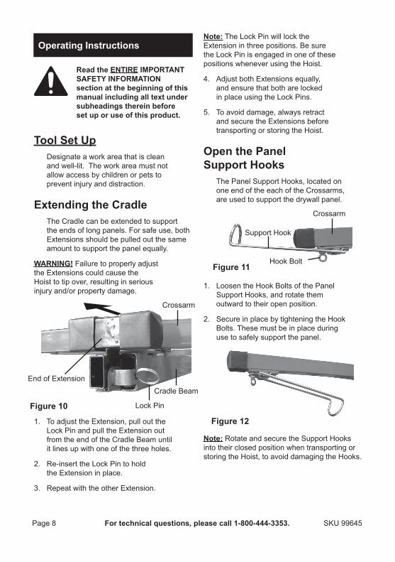
tool set upDesignate a work area that is clean and well‑lit. The work area must not allow access by children or pets to prevent injury and distraction.
extending the cradleThe Cradle can be extended to support the ends of long panels. For safe use, both Extensions should be pulled out the same amount to support the panel equally.
WarnInG! Failure to properly adjust the Extensions could cause the Hoist to tip over, resulting in serious injury and/or property damage.
1.
Cradle BeamEnd of Extension
Lock PinFigure 10
Crossarm
To adjust the Extension, pull out the Lock Pin and pull the Extension out from the end of the Cradle Beam until it lines up with one of the three holes.
2. Re‑insert the Lock Pin to hold the Extension in place.
3. Repeat with the other Extension.
note: The Lock Pin will lock the Extension in three positions. Be sure the Lock Pin is engaged in one of these positions whenever using the Hoist.
4. Adjust both Extensions equally, and ensure that both are locked in place using the Lock Pins.
5. To avoid damage, always retract and secure the Extensions before transporting or storing the Hoist.
open the Panel support Hooks
The Panel Support Hooks, located on one end of the each of the Crossarms, are used to support the drywall panel.
1.
Figure 11
Crossarm
Support Hook
Hook Bolt
Loosen the Hook Bolts of the Panel Support Hooks, and rotate them outward to their open position.
2. Secure in place by tightening the Hook Bolts. These must be in place during use to safely support the panel.
Figure 12
note: Rotate and secure the Support Hooks into their closed position when transporting or storing the Hoist, to avoid damaging the Hooks.
Page 9For technical questions, please call 1‑800‑444‑3353.SKU 99645
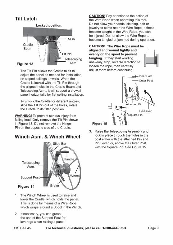
tilt latch
Figure 13
Cradle Beam
Telescoping Asm.
Tilt Pin
locked position:
R‑Pin
The Tilt Pin allows the Cradle to tilt to adjust the panel as needed for installation on sloped ceilings or walls. When the Cradle is locked with the Tilt Pin through the aligned holes in the Cradle Beam and Telescoping Asm., it will support a drywall panel horizontally for flat ceiling installation.
To unlock the Cradle for different angles, slide the Tilt Pin out of the holes, rotate the Cradle to its tilted position.
WarnInG! To prevent serious injury from falling load: Only remove the Tilt Pin shown in Figure 13. Do not remove the Hinge Pin on the opposite side of the Cradle.
Winch asm. & Winch Wheel
1.
Support Post
Slide Bar
Telescoping Asm.
Wheel
Handle
BrakeFigure 14
The Winch Wheel is used to raise and lower the Cradle, which holds the panel. This is done by means of a Wire Rope which wraps around a Spool in the Winch.
2. If necessary, you can grasp the end of the Support Post for leverage when raising a panel.
cautIon! Pay attention to the action of the Wire Rope when operating this tool. Do not allow your hands, clothing, hair or jewelry to come near the Wire Rope. If these become caught in the Wire Rope, you can be injured. Do not allow the Wire Rope to become tangled or jammed during operation.
cautIon! the Wire rope must be aligned and wound tightly and evenly on the spool to prevent tangling. If they start winding unevenly, stop, reverse direction to loosen the rope, then carefully adjust them before continuing.
3.
Square Pin
Attached Pin
Inner Post
Pin Lever
Outer Post
Figure 15
Raise the Telescoping Assembly and lock in place through the holes in the post either with the attached Pin and Pin Lever, or, above the Outer Post with the Square Pin. See Figure 15.
Page 10 For technical questions, please call 1‑800‑444‑3353. SKU 99645
operation
safety checks Before operation1. Carefully inspect the Hoist
before operating it.
2. Inspect the tool for wear or damage. Pay special attention to any wear or damage to the Wire Rope.
3. Be sure the Winch components are clean and dry before operation.
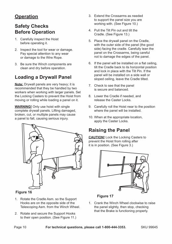
loading a Drywall Panelnote: Drywall panels are very heavy; it is recommended that they be handled by two workers when working with larger panels. Set the Locking Casters to prevent the Hoist from moving or rolling while loading a panel on it.
WarnInG! Only use hoist with single complete drywall panels. Lifting damaged, broken, cut, or multiple panels may cause a panel to fall, causing serious injury.
1.
Figure 16
Rotate the Cradle Asm. so the Support Hooks are on the opposite side of the Telescoping Asm. from the Winch Wheel.
2. Rotate and secure the Support Hooks to their open position. (See Figure 11.)
3. Extend the Crossarms as needed to support the panel size you are working with. (See Figure 10.)
4. Pull the Tilt Pin out and tilt the Cradle. (See Figure 13.)
5. Place the drywall panel on the Cradle, with the outer side of the panel (the good side) facing the cradle. Carefully lean the panel on the Crossarms, being careful not to damage the edges of the panel.
6. If the panel will be installed on a flat ceiling, tilt the Cradle back to its horizontal position and lock in place with the Tilt Pin. If the panel will be installed on a side wall or sloped ceiling, leave the Cradle tilted.
7. Check to see that the panel is secure and balanced.
8. Lower the Cradle if needed, and release the Caster Locks.
9. Carefully roll the Hoist near to the position where the panel will be installed.
10. When at the appropriate location, apply the Caster Locks.
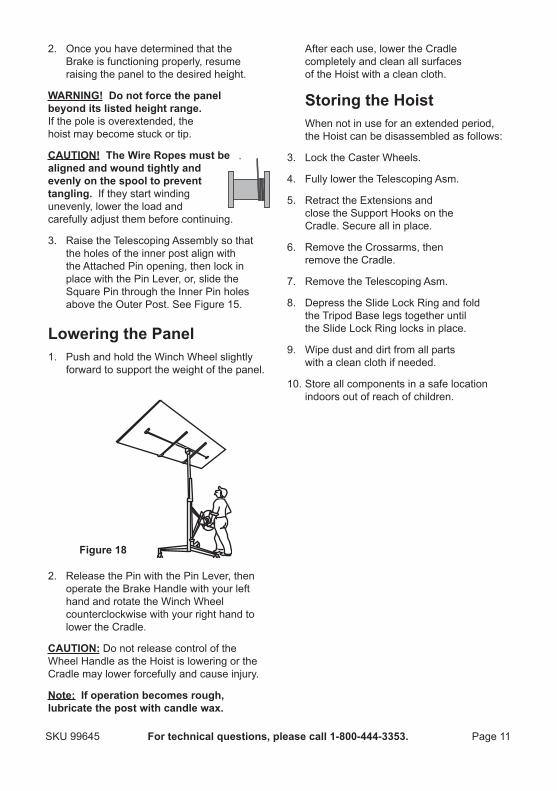
raising the PanelcautIon! Lock the Locking Casters to prevent the Hoist from rolling after it is in position. (See Figure 3.)
1.
Figure 17
Crank the Winch Wheel clockwise to raise the panel slightly, then stop, checking that the Brake is functioning properly.
Page 11For technical questions, please call 1‑800‑444‑3353.SKU 99645
2. Once you have determined that the Brake is functioning properly, resume raising the panel to the desired height.
WarnInG! Do not force the panel beyond its listed height range. If the pole is overextended, the hoist may become stuck or tip.
cautIon! the Wire ropes must be aligned and wound tightly and evenly on the spool to prevent tangling. If they start winding unevenly, lower the load and carefully adjust them before continuing.
3. Raise the Telescoping Assembly so that the holes of the inner post align with the Attached Pin opening, then lock in place with the Pin Lever, or, slide the Square Pin through the Inner Pin holes above the Outer Post. See Figure 15.
lowering the Panel1. Push and hold the Winch Wheel slightly
forward to support the weight of the panel.
2.
Figure 18
Release the Pin with the Pin Lever, then operate the Brake Handle with your left hand and rotate the Winch Wheel counterclockwise with your right hand to lower the Cradle.
cautIon: Do not release control of the Wheel Handle as the Hoist is lowering or the Cradle may lower forcefully and cause injury.
note: If operation becomes rough, lubricate the post with candle wax.
After each use, lower the Cradle completely and clean all surfaces of the Hoist with a clean cloth.
storing the HoistWhen not in use for an extended period, the Hoist can be disassembled as follows:
3. Lock the Caster Wheels.
4. Fully lower the Telescoping Asm.
5. Retract the Extensions and close the Support Hooks on the Cradle. Secure all in place.
6. Remove the Crossarms, then remove the Cradle.
7. Remove the Telescoping Asm.
8. Depress the Slide Lock Ring and fold the Tripod Base legs together until the Slide Lock Ring locks in place.
9. Wipe dust and dirt from all parts with a clean cloth if needed.
10. Store all components in a safe location indoors out of reach of children.
Page 12 For technical questions, please call 1‑800‑444‑3353. SKU 99645
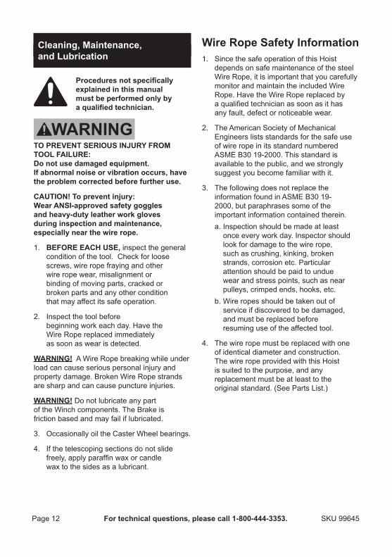
cleaning, maintenance, and lubrication
Proceduresnotspecificallyexplained in this manual must be performed only by aqualifiedtechnician.
to PreVent serIous InjurY From tool FaIlure: Do not use damaged equipment. If abnormal noise or vibration occurs, have the problem corrected before further use.
cautIon! to prevent injury: Wear ansI‑approved safety goggles and heavy‑duty leather work gloves during inspection and maintenance, especially near the wire rope.
1. BeFore eacH use, inspect the general condition of the tool. Check for loose screws, wire rope fraying and other wire rope wear, misalignment or binding of moving parts, cracked or broken parts and any other condition that may affect its safe operation.
2. Inspect the tool before beginning work each day. Have the Wire Rope replaced immediately as soon as wear is detected.
WarnInG! A Wire Rope breaking while under load can cause serious personal injury and property damage. Broken Wire Rope strands are sharp and can cause puncture injuries.
WarnInG! Do not lubricate any part of the Winch components. The Brake is friction based and may fail if lubricated.
3. Occasionally oil the Caster Wheel bearings.
4. If the telescoping sections do not slide freely, apply paraffin wax or candle wax to the sides as a lubricant.
Wire rope safety Information1. Since the safe operation of this Hoist
depends on safe maintenance of the steel Wire Rope, it is important that you carefully monitor and maintain the included Wire Rope. Have the Wire Rope replaced by a qualified technician as soon as it has any fault, defect or noticeable wear.
2. The American Society of Mechanical Engineers lists standards for the safe use of wire rope in its standard numbered ASME B30 19‑2000. This standard is available to the public, and we strongly suggest you become familiar with it.
3. The following does not replace the information found in ASME B30 19‑2000, but paraphrases some of the important information contained therein.a. Inspection should be made at least
once every work day. Inspector should look for damage to the wire rope, such as crushing, kinking, broken strands, corrosion etc. Particular attention should be paid to undue wear and stress points, such as near pulleys, crimped ends, hooks, etc.
b. Wire ropes should be taken out of service if discovered to be damaged, and must be replaced before resuming use of the affected tool.
4. The wire rope must be replaced with one of identical diameter and construction. The wire rope provided with this Hoist is suited to the purpose, and any replacement must be at least to the original standard. (See Parts List.)
Page 13For technical questions, please call 1‑800‑444‑3353.SKU 99645
Please reaD tHe FolloWInG careFullYTHE MANUFACTURER AND/OR DISTRIBUTOR HAS PROVIDED THE PARTS LIST AND ASSEMBLY DIAgRAM IN THIS MANUAL AS A REFERENCE TOOL ONLY. NEITHER THE MANUFACTURER OR DISTRIBUTOR MAKES ANY REPRESENTATION OR WARRANTY OF ANY KIND TO THE BUYER THAT HE OR SHE IS qUALIFIED TO MAKE ANY REPAIRS TO THE PRODUCT, OR THAT HE OR SHE IS qUALIFIED TO REPLACE ANY PARTS OF THE PRODUCT. IN FACT, THE MANUFACTURER AND/OR DISTRIBUTOR ExPRESSLY STATES THAT ALL REPAIRS AND PARTS REPLACEMENTS SHOULD BE UNDERTAKEN BY CERTIFIED AND LICENSED TECHNICIANS, AND NOT BY THE BUYER. THE BUYER ASSUMES ALL RISK AND LIABILITY ARISINg OUT OF HIS OR HER REPAIRS TO THE ORIgINAL PRODUCT OR REPLACEMENT PARTS THERETO, OR ARISINg OUT OF HIS OR HER INSTALLATION OF REPLACEMENT PARTS THERETO.
Page 14 For technical questions, please call 1‑800‑444‑3353. SKU 99645
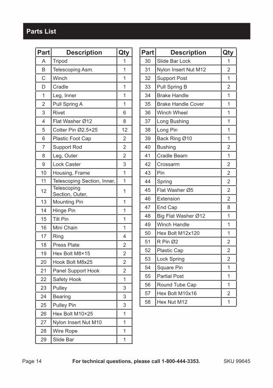
Part Description QtyA Tripod 1B Telescoping Asm. 1C Winch 1D Cradle 11 Leg, Inner 12 Pull Spring A 13 Rivet 64 Flat Washer Ø12 85 Cotter Pin Ø2.5×25 126 Plastic Foot Cap 27 Support Rod 28 Leg, Outer 29 Lock Caster 310 Housing, Frame 111 Telescoping Section, Inner, 1
12 Telescoping Section, Outer, 1
13 Mounting Pin 114 Hinge Pin 115 Tilt Pin 116 Mini Chain 117 Ring 418 Press Plate 219 Hex Bolt M8×15 220 Hook Bolt M8x25 221 Panel Support Hook 222 Safety Hook 123 Pulley 324 Bearing 325 Pulley Pin 326 Hex Bolt M10×25 127 Nylon Insert Nut M10 128 Wire Rope 129 Slide Bar 1
Part Description Qty30 Slide Bar Lock 131 Nylon Insert Nut M12 232 Support Post 133 Pull Spring B 234 Brake Handle 135 Brake Handle Cover 136 Winch Wheel 137 Long Bushing 138 Long Pin 139 Back Ring Ø10 140 Bushing 241 Cradle Beam 142 Crossarm 243 Pin 244 Spring 245 Flat Washer Ø5 246 Extension 247 End Cap 848 Big Flat Washer Ø12 149 Winch Handle 150 Hex Bolt M12x120 151 R Pin Ø2 252 Plastic Cap 253 Lock Spring 254 Square Pin 155 Partial Post 156 Round Tube Cap 157 Hex Bolt M10x16 258 Hex Nut M12 1
Parts list
Page 15For technical questions, please call 1‑800‑444‑3353.SKU 99645
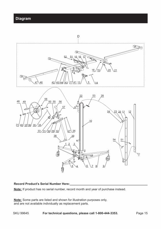
Diagram
D
record Product’s serial number Here:
note: If product has no serial number, record month and year of purchase instead.
note: Some parts are listed and shown for illustration purposes only, and are not available individually as replacement parts.
90 Day Warranty
Harbor Freight Tools Co. makes every effort to assure that its products meet high quality and durability standards, and warrants to the original purchaser that this product is free from defects in materials and workmanship for the period of 90 days from the date of purchase. This warranty does not apply to damage due directly or indirectly, to misuse, abuse, negligence or accidents, repairs or alterations outside our facilities, criminal activity, improper installation, normal wear and tear, or to lack of maintenance. We shall in no event be liable for death, injuries to persons or property, or for incidental, contingent, special or consequential damages arising from the use of our product. Some states do not allow the exclusion or limitation of incidental or consequential damages, so the above limitation of exclusion may not apply to you. THIS WARRANTY IS ExPRESSLY IN LIEU OF ALL OTHER WARRANTIES, ExPRESS OR IMPLIED, INCLUDINg THE WARRANTIES OF MERCHANTABILITY AND FITNESS.
To take advantage of this warranty, the product or part must be returned to us with transportation charges prepaid. Proof of purchase date and an explanation of the complaint must accompany the merchandise. If our inspection verifies the defect, we will either repair or replace the product at our election or we may elect to refund the purchase price if we cannot readily and quickly provide you with a replacement. We will return repaired products at our expense, but if we determine there is no defect, or that the defect resulted from causes not within the scope of our warranty, then you must bear the cost of returning the product.
This warranty gives you specific legal rights and you may also have other rights which vary from state to state.
3491 Mission Oaks Blvd. • PO Box 6009 • Camarillo, CA 93011 • (800) 444-3353