Embed Size (px)
Citation preview
Engineering Specification Electrical
Engi
neer
ing
Spec
ifica
tion
EP 04 02 00 01 SP
1500V DC HIGH SPEED RECTIFIER CIRCUIT BREAKER
Version 2.1
Issued April 2013
Reconfirmed 10 July 2019
Owner: Chief Engineer, Electrical
Approved by:
Neal Hook Chief Engineer Electrical
Authorised by:
Neal Hook Chief Engineer Electrical
Disclaimer This document was prepared for use on the RailCorp Network only. RailCorp makes no warranties, express or implied, that compliance with the contents of this document shall be sufficient to ensure safe systems or work or operation. It is the document user’s sole responsibility to ensure that the copy of the document it is viewing is the current version of the document as in use by RailCorp. RailCorp accepts no liability whatsoever in relation to the use of this document by any party, and RailCorp excludes any liability which arises in any manner by the use of this document. Copyright The information in this document is protected by Copyright and no part of this document may be reproduced, altered, stored or transmitted by any person without the prior consent of RailCorp.
UNCONTROLLED WHEN PRINTED Page 1 of 22

RailCorp Engineering Specification — Electrical 1500V DC High Speed Rectifier Circuit Breaker EP 04 02 00 01 SP
© RailCorp Page 2 of 22 Issued April 2013 UNCONTROLLED WHEN PRINTED Version 2.1
Document control
Version Date Summary of change December 2004 Last Technical Review
2.0 May 2010 Application of TMA 400 format 2.1 April 2013 Update template

RailCorp Engineering Specification — Electrical 1500V DC High Speed Rectifier Circuit Breaker EP 04 02 00 01 SP
© RailCorp Page 3 of 22 Issued April 2013 UNCONTROLLED WHEN PRINTED Version 2.1
Contents
1 Introduction .............................................................................................................................5 2 References...............................................................................................................................5 2.1 Australian and International Standards.....................................................................................5 2.2 Drawings ...................................................................................................................................5 2.3 RailCorp Standards...................................................................................................................5 3 Definitions and Abbreviations ...............................................................................................6 4 Functional Characteristics.....................................................................................................7 4.1 General......................................................................................................................................7 4.2 Interchangeability ......................................................................................................................8 5 Performance Characteristics .................................................................................................8 5.1 General......................................................................................................................................8 5.2 Voltage Rating...........................................................................................................................8 5.3 Current Rating & Maximum Fault Levels ..................................................................................9 5.4 Reliability ...................................................................................................................................9 5.5 Arc Voltage................................................................................................................................9 5.6 Reverse current Setting ............................................................................................................9 6 Technical Characteristics.....................................................................................................10 6.1 Mounting of Controls and Auxiliary Equipment.......................................................................10 6.2 Control of Circuit breakers ......................................................................................................10 6.3 Control Supplies......................................................................................................................10
6.3.1 General ....................................................................................................................10 6.3.2 125V Control operation............................................................................................11 6.3.3 125V Controls supply...............................................................................................11
6.4 Auxiliary Indication Contacts. ..................................................................................................11 6.5 Manual Operation....................................................................................................................11 6.6 Mechanical and Illuminated Open/Close Indicator .................................................................11 6.7 Arc Chute ................................................................................................................................12 6.8 Holding coil variable resistor ...................................................................................................12 6.9 Operation Counter...................................................................................................................12 6.10 Materials..................................................................................................................................12 6.11 Warning signs .........................................................................................................................12 6.12 Environment ............................................................................................................................12 6.13 Noise Emissions......................................................................................................................12 7 Routine Maintenance Period................................................................................................13 8 Integrated System Support Requirements.........................................................................13 8.1 Integrated Support Objectives ................................................................................................13 8.2 Equipment supplier deliverable...............................................................................................13 9 Routine Tests ........................................................................................................................14 9.1 General....................................................................................................................................14 9.2 Dielectric Tests........................................................................................................................14
9.2.1 Acceptance Criteria for Dielectric Tests ..................................................................14 9.2.2 Main 1500V dc circuit to Frame...............................................................................14
RailCorp Engineering Specification — Electrical 1500V DC High Speed Rectifier Circuit Breaker EP 04 02 00 01 SP
© RailCorp Page 4 of 22 Issued April 2013 UNCONTROLLED WHEN PRINTED Version 2.1
9.2.3 Across the Main Contacts........................................................................................14 9.2.4 125V Circuits to Main 1500V dc circuit....................................................................14 9.2.5 125 V Circuits to Frame...........................................................................................14
9.3 Repeatability of the Trip Current Value...................................................................................14 10 Type Tests .............................................................................................................................15 10.1 General....................................................................................................................................15 11 Data Set associated with the Equipment............................................................................15 11.1 Test Results ............................................................................................................................15 11.2 Life Cycle Costing ...................................................................................................................15 11.3 Information to be Provided......................................................................................................15 Appendix A Technical Schedule ...............................................................................................16 Appendix B Request for Tender Checklist...............................................................................19 Appendix C Requirements for Technical Aspects of Tender Evaluation .............................20 Appendix D RailCorp Standard Type Tests .............................................................................21

RailCorp Engineering Specification — Electrical 1500V DC High Speed Rectifier Circuit Breaker EP 04 02 00 01 SP
© RailCorp Page 5 of 22 Issued April 2013 UNCONTROLLED WHEN PRINTED Version 2.1
1 Introduction This document sets out the whole-of-life performance requirements for dc rectifier circuit breakers used on the RailCorp 1500V dc system.
It provides all the necessary information to ensure that the dc circuit breakers are electrically suitable for the RailCorp 1500V network. (eg fault levels, operation, etc.)
It requires that the circuit breakers be physically interchangeable with the existing truck-mounted circuit breakers, mounted within brick cubicles.
2 References The following documents contain provisions that, through reference in this text, provide further information and constitute provisions of this specification. At the time of publication, the editions indicated below were valid.
2.1 Australian and International Standards AS 2700:1996 Colour standards for general purposes. IEC 60051-2:1984 Direct acting indicating analogue electrical measuring instruments and
their accessories Part 2: Special requirements for ammeters and voltmeters
EN 50123 – 1 Railway Applications – Fixed installations, DC switchgear Part 1: General
EN 50123 – 2 Railway Applications – Fixed installations, DC switchgear Part 1: DC circuit breakers
2.2 Drawings The following drawings form part of this specification:
EL0006165 1500V DCCB Base Frame Assembly EL0006166 1500V DCCB Truck Outline EL0006167 1500V DCCB Truck Front Panel Layout EL0227687 1500V DCCB Busbars and Insulating Plate Details EL0006169 1500V DCCB Racking Handle Assembly EL0006170 1500V DCCB Brick Cubicle Layout EL0006281 1500V DCCB External Control Wiring Connections
2.3 RailCorp Standards Several significant sets of requirements applicable to 1500V High Speed DC Rectifier Circuit Breakers are common to other classes of equipment and are set out in the following RailCorp standards. The equipment shall comply with the relevant requirements set out therein.
EP 00 00 00 13 SP Design Ranges for Ambient Conditions for Electric Power Equipment. EP 00 00 00 12 SP Electric Power Equipment – Integrated Support Requirements. EP 00 00 00 15 SP Common Requirements for Electric Power Equipment. EP 03 02 00 01 SP Rectifier Controls and Protection EP 06 00 00 01 SP System Substation Battery

RailCorp Engineering Specification — Electrical 1500V DC High Speed Rectifier Circuit Breaker EP 04 02 00 01 SP
© RailCorp Page 6 of 22 Issued April 2013 UNCONTROLLED WHEN PRINTED Version 2.1
EP 90 20 00 01 SP 1500V DC Equipment Current Ratings EP 90 20 00 02 SP 1500V System Voltage Ratings
3 Definitions and Abbreviations Close An operator initiated action which causes the circuit breaker to close. May be either by SCADA or by using the manual operating handle.
Electrically Closed The complete closing action of the circuit breaker is caused by electrical means, typically by a solenoid or closing coil.
Main 1500V Circuit The main current carrying part of the circuit breaker which is alive at 1500V to frame. It excludes the control circuitry, which can be disconnected from the rest of the circuit by fuses or links, but includes the arc chute, blowout coils, etc.
Floating The system condition when a common return path used as the zero voltage reference level for the equipment or system is not necessarily connected to earth.
Trip Free Action The circuit breaker shall not be able to be held closed, either by hand or electrically, if it is closed onto a current that otherwise would cause the breaker to open.
Nominal voltage (Un) Voltage by which an installation or part of an installation is designated
Highest system voltage (Umax) Highest value given for the voltage in the continuous operating condition
Lowest system voltage (Umin) Lowest value given for the voltage in the continuous operating condition
Rated insulation voltage (UNm) Maximum value of the dc voltage for which the equipment is designed in respect to its insulation
Rated voltage (UNe) Voltage value given by the manufacturer, which combined with rated service current, determines the utilisation of the equipment and to which the corresponding tests and utilisation categories, if any, relate
Maximum arc voltage (Ǘarc) Maximum voltage appearing across the switching device during arcing
Conventional free-air thermal current (Ith) Current which may be used for the temperature-rise test of an equipment in free-air. This value is equal to or greater than the maximum value of the rated service current INe of the equipment
Rated service current (INe) Value of current stated by manufacturer, taking into account the rated voltage (UNe), the continuous duty and the utilisation category and the protective enclosure type, if any
Conductive part Part capable of conducting current, although it may not necessarily be used for carrying service current
Clearance Distance between any conductive parts along a string stretched along the shortest distance between these conductive parts
Clearance to earth Distance between any conductive part and any part earthed or intended to be earthed

RailCorp Engineering Specification — Electrical 1500V DC High Speed Rectifier Circuit Breaker EP 04 02 00 01 SP
© RailCorp Page 7 of 22 Issued April 2013 UNCONTROLLED WHEN PRINTED Version 2.1
Critical current (Ic) Value of breaking current, less than rated short circuit breaking current, at which the arcing time is a maximum and is significantly longer than at the rated short circuit breaking current
Rectifier circuit breaker (R ) Circuit breaker that connects the output of the rectifier to the energised 1500V busbar. Rectifier circuit breakers trip in the reverse direction to disconnect the rectifier from the dc busbar in the event of a rectifier fault. These circuit breakers are unidirectional in operation. Reverse refers to the normal flow of energy.
4 Functional Characteristics
4.1 General The circuit breakers covered by this Specification will be used for the control and protection of 2.5MW, 4MW or 5MW, 1500V rectifiers in a traction substation on the RailCorp railway system.
The nominal voltage (Un) of the traction supply is 1500V dc. The overhead conductors of the system are positive with respect to the rails, which are unearthed but normally close to earth potential.
The circuit breaker is required to detect faults on the 1500V rectifier and to clear such faults as quickly as possible, to minimise damage to equipment, and with no damage to the circuit breaker.
The circuit breakers shall be physically interchangeable with truck mounted circuit breakers installed in substations in recent years.
The circuit breaker will be connected between the 1500V positive of the rectifier and the positive busbar. The circuit breaker shall open automatically only when the direction of the fault current through the circuit breaker is from the positive busbar to the Rectifier. It shall not open automatically when current of any magnitude flows from the Rectifier towards the busbar.
The circuit breaker shall detect faults by current magnitude and rate of rise of current.
All equipment on the circuit breaker is to be naturally cooled.
SCADA equipment will be installed in the substation to provide remote open and close signals for the control of the circuit breakers and remote indication of whether the circuit breakers are open or closed. Other remote indication and control as specified in this document will interface with SCADA.
The opening and closing action of the rectifier circuit breaker shall be by a magnetically held type circuit. Mechanically latched circuit breakers are not acceptable.

RailCorp Engineering Specification — Electrical 1500V DC High Speed Rectifier Circuit Breaker EP 04 02 00 01 SP
© RailCorp Page 8 of 22 Issued April 2013 UNCONTROLLED WHEN PRINTED Version 2.1
4.2 Interchangeability The circuit breakers shall be physically interchangeable with truck mounted circuit breakers installed in substations in recent years.
• The circuit breakers and trucks shall be equivalent in dimension and type to those shown on Drawings EL0006166 “1500V DCCB Truck Outline” , EL0006167 “1500V DCCB Truck Front Panel Outline” and EL0006170 “1500V DCCB Brick Cubicle Layout”. The dimensions shown on these drawings are critical and must be strictly adhered to.The connections to the external control wiring are to be made using “Cannon” type Multipin Plug and socket - ATC 02 A28 - 11P - F80 and ATC 06 A28 - 11S - F80 respectively, or plug and socket assemblies which are exactly compatible to the “Cannon” type Plug and Socket. The circuit breakers are to be wired in accordance with Drawing EL0006281 “1500V D.C.C.B. External Control Wiring Connections” and are to be complete with the neoprene rubber tubing and 1000 mm lengths of wire as shown on the drawing.
Circuit breaker base frames are the fixed portion onto which the circuit breaker is racked-in. The base frames shall comply with drawing EL0006165 “1500V DCCB Base Frame Assembly”.
Bus bar jointing pieces and insulating pieces are used to connect the 1500 V bus portion of each base frame to its adjacent bus. The bus bar jointing and insulating pieces shall comply with drawing EL0227687 “1500V DCCB Busbars and Insulating Plate Details”
The circuit breaker shall be suitable to operate with arc expulsion spaces no greater than 3870mm above floor level.
5 Performance Characteristics
5.1 General The circuit breakers shall be indoor, truck mounted, single pole, electrically closed, electrically opened, trip-free suitable for use in a nominal 1500V dc circuit and specifically designed for traction duty.
Each circuit breaker shall be supplied complete, with all of the auxiliary equipment necessary for control, protection and operation, mounted on the truck.
The dccb’s will be installed in brick cubicles, in a manner that prevents damage to other dccb’s or substation equipment, in the event of a dccb flashover.
Metal-clad circuit breakers will not be considered.
5.2 Voltage Rating The circuit breaker shall operate satisfactorily with voltages in the range of 1000 to 2050V dc. Continuous operation at 2000V is not anticipated. The permissible temperature rise shall not be exceeded when the equipment is operated continuously at 1750V.
Voltage ratings are set out in document EP 90 20 00 02 SP – 1500V System Voltage Ratings.
RailCorp Engineering Specification — Electrical 1500V DC High Speed Rectifier Circuit Breaker EP 04 02 00 01 SP
© RailCorp Page 9 of 22 Issued April 2013 UNCONTROLLED WHEN PRINTED Version 2.1
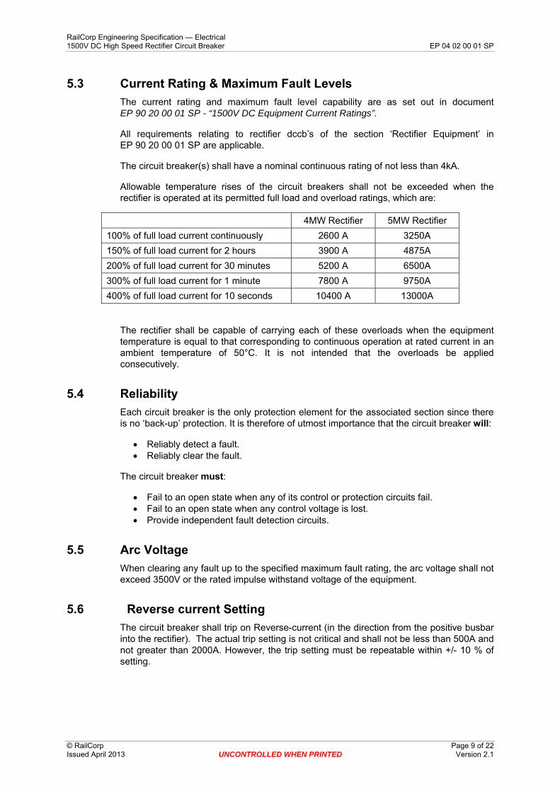
5.3 Current Rating & Maximum Fault Levels The current rating and maximum fault level capability are as set out in document EP 90 20 00 01 SP - “1500V DC Equipment Current Ratings”.
All requirements relating to rectifier dccb’s of the section ‘Rectifier Equipment’ in EP 90 20 00 01 SP are applicable.
The circuit breaker(s) shall have a nominal continuous rating of not less than 4kA.
Allowable temperature rises of the circuit breakers shall not be exceeded when the rectifier is operated at its permitted full load and overload ratings, which are:
4MW Rectifier 5MW Rectifier 100% of full load current continuously 2600 A 3250A 150% of full load current for 2 hours 3900 A 4875A 200% of full load current for 30 minutes 5200 A 6500A 300% of full load current for 1 minute 7800 A 9750A 400% of full load current for 10 seconds 10400 A 13000A
The rectifier shall be capable of carrying each of these overloads when the equipment temperature is equal to that corresponding to continuous operation at rated current in an ambient temperature of 50°C. It is not intended that the overloads be applied consecutively.
5.4 Reliability Each circuit breaker is the only protection element for the associated section since there is no ‘back-up’ protection. It is therefore of utmost importance that the circuit breaker will:
• Reliably detect a fault. • Reliably clear the fault.
The circuit breaker must:
• Fail to an open state when any of its control or protection circuits fail. • Fail to an open state when any control voltage is lost. • Provide independent fault detection circuits.
5.5 Arc Voltage When clearing any fault up to the specified maximum fault rating, the arc voltage shall not exceed 3500V or the rated impulse withstand voltage of the equipment.
5.6 Reverse current Setting The circuit breaker shall trip on Reverse-current (in the direction from the positive busbar into the rectifier). The actual trip setting is not critical and shall not be less than 500A and not greater than 2000A. However, the trip setting must be repeatable within +/- 10 % of setting.
RailCorp Engineering Specification — Electrical 1500V DC High Speed Rectifier Circuit Breaker EP 04 02 00 01 SP
© RailCorp Page 10 of 22 Issued April 2013 UNCONTROLLED WHEN PRINTED Version 2.1
6 Technical Characteristics
6.1 Mounting of Controls and Auxiliary Equipment Each circuit breaker (and truck if used) shall be self-contained with all of the auxiliary and control equipment required for the circuit breaker. The equipment shall be arranged such that cables are not flexed when doors are opened or the circuit breaker is racked-in and also to prevent the circuit breaker being racked-in unless the arc chute is in its correct position. An interlock shall be provided to prevent the circuit breaker from being withdrawn or racked-in while the circuit breaker is closed.
All conductors carrying 1500V dc shall be physically segregated from voltages at lower potential (including ‘Earth’) by a distance which prevents any flash-over from high to low voltage conductors. All equipment connected to the 1500V dc circuit (such as coils, resistors etc.) shall also be adequately segregated and comprise minimum protection against flash-over.
The minimum clearance in air between adjacent uninsulated 1500V dc conductors and between uninsulated 1500V dc conductors and earthed metalwork shall not be less than 25mm. The minimum creepage distance shall not be less than 37mm, of which at least 25mm shall be vertical.
Equipment connected to the 1500V dc circuit within switchboards shall be segregated from all other control and auxiliary equipment operating at lower voltages by suitable barriers or a physical separation of at least 50mm – as to AS/NZS 3000. All 1500V wiring shall be harnessed separately from other control and auxiliary wiring, and shall be designed for a test voltage of at least 5kV rms to earth for 1 minute.
6.2 Control of Circuit breakers The circuit breakers shall be arranged for operation by electrical control from the Rectifier Control and Protection Equipment.
The Rectifier Control and Protection Equipment will provide a +125V dc signal while ever the DCCB is to be closed. The circuit breaker shall close without delay when this signal is applied. The close operation shall be trip-free. The circuit breaker shall open without delay when this signal is removed.
The circuit shall provide a voltage free, normally open contact that closes if the circuit breaker trips on reverse current.
6.3 Control Supplies
6.3.1 General The substation battery system is 125V dc, as outlined in EP 06 00 00 01 System Substation Battery.
Control supply for the operation of the circuit breaker shall only be obtained from the 125V dc battery and/or the 1500V system. All wiring connected through the circuit breaker control plug/socket shall be rated for 125V.
RailCorp Engineering Specification — Electrical 1500V DC High Speed Rectifier Circuit Breaker EP 04 02 00 01 SP
© RailCorp Page 11 of 22 Issued April 2013 UNCONTROLLED WHEN PRINTED Version 2.1
6.3.2 125V Control operation The 125V control equipment shall be continuously rated for operation on a nominal 125V dc supply and shall be capable of satisfactory operation with voltage variations of +/- 20% of the nominal 125V. The actual voltage output of the 125V battery system at any given time will fall within these voltage variations.
All 125V control wiring shall be designed to withstand a test voltage of 1.5kV rms to frame for 1 minute and 5kV rms to main 1500V circuit for 1 minute.
The current in the 125V holding coil circuit shall not exceed 2.1A peak and 1.5A continuous.
The current in the 125V closing coil circuit shall not exceed 70A peak. The current in the 125V auxiliary control circuit shall not exceed 20A peak and 10A continuous.
6.3.3 125V Controls supply The 125V supply for controls are supplied from the Rectifier Control cubicle.
The 125V holding coil circuit shall be protected by HRC fuses in both the +ve and –ve conductors. The fuses supplied shall be of proved breaking capacity. Expulsion type fuses shall not be used.
6.4 Auxiliary Indication Contacts. In addition to the any contacts required for the control and operation of the circuit breaker, two normally open and two normally closed, voltage-free auxiliary contacts shall be provided to indicate if the circuit breaker is open or closed. All auxiliary contacts shall have a minimum make and break rating of 1 Amp at 125V dc and 5A at 240V ac and shall have dust proof covers. They shall withstand a voltage of 5kV rms to the main 1500V circuit for 1 minute. The contacts shall be operated by a linkage directly from the main contacts, not from the driving/operating mechanism.
6.5 Manual Operation It shall be possible to close the circuit breaker by hand with a trip free action (see Section 3). A handle is to be provided to facilitate closing operation during maintenance.
6.6 Mechanical and Illuminated Open/Close Indicator The circuit breaker shall be fitted with a mechanically operated indicator, indelibly marked, to show whether the circuit breaker is open or closed. It is not necessary that this indicator is visible from the front of the circuit breaker truck in its normal racked-in position. The word OPEN shall be visible only if the circuit breaker is open and the word CLOSED shall be visible only if the circuit breaker is closed.
Visual indication of the state of the circuit breaker shall be provided by LEDs mounted on the front of the truck.
For both mechanical and LED indicators the colour green shall indicate the OPEN condition and the colour red shall indicate the CLOSED condition.
RailCorp Engineering Specification — Electrical 1500V DC High Speed Rectifier Circuit Breaker EP 04 02 00 01 SP
© RailCorp Page 12 of 22 Issued April 2013 UNCONTROLLED WHEN PRINTED Version 2.1
6.7 Arc Chute An Arc Chute Barrier shall be provided and mounted by the manufacturer. The barrier shall be able to prevent an arc from coming into contact with any metalwork in the area of arc expulsion.
6.8 Holding coil variable resistor The holding coil variable resistor (where fitted) shall be mounted on the circuit breaker such that there is adequate minimum creepage distance between the resistor and frame and the resistor and all other wiring on the circuit breaker.
If an adequate creepage distance cannot be achieved, the resistor must be encapsulated by insulation, which will prevent flashover.
6.9 Operation Counter A non-resettable, memory-retentive counter shall be provided to record the number of openings on the circuit breaker.
6.10 Materials Asbestos is not to be used in any part of the equipment.
Special attention is required to use of materials with the ability to resist moisture and fire; materials used should be of the self-extinguishing type, such that the risk of propagation of fire from one cubicle to another is minimised.
Materials and products of combustion shall be practically halogen free and shall contribute with limited quantity of thermal energy to a fire.
6.11 Warning signs A warning sign shall be provided on the door of the circuit breaker in accordance with AS/NZS 3000.
6.12 Environment The circuit breakers will be installed inside traction substation buildings. The equipment shall comply with the requirements of EP 00 00 00 13 SP Design Ranges for Ambient Conditions for Electric Power Equipment.
6.13 Noise Emissions The peak sound pressure level during the interruption of a fault shall be stated in the schedule at Appendix A. The sound pressure level shall be stated for the circuit breaker mounted on the truck, with the truck in a standard cubicle and at a point 1m in front of the truck. The sound pressure level quoted shall be the maximum level over the full range of fault current interruption.
RailCorp Engineering Specification — Electrical 1500V DC High Speed Rectifier Circuit Breaker EP 04 02 00 01 SP
© RailCorp Page 13 of 22 Issued April 2013 UNCONTROLLED WHEN PRINTED Version 2.1
7 Routine Maintenance Period Routine maintenance shall not be required more frequently than:
• Once every 5 years
8 Integrated System Support Requirements
8.1 Integrated Support Objectives The tenderer must establish and provide the information required to operate and maintain the equipment throughout its operational life, in a cost effective manner and to a level that is consistent with the planned operational performance and usage of the DC Rectifier Circuit Breaker.
This includes:
• Specifying Maintenance Requirements • Spares Support • Operations and Maintenance Manuals • Training, and • Support Equipment and Tooling
8.2 Equipment supplier deliverable The Integrated support requirements are a significant deliverable in the procurement of a new DC Rectifier Circuit Breaker. Manuals, training, documentation and other support deliverable's shall be in accordance with EP 00 00 00 12 SP Electrical Power Equipment - Integrated Support Requirements.
RailCorp Engineering Specification — Electrical 1500V DC High Speed Rectifier Circuit Breaker EP 04 02 00 01 SP
© RailCorp Page 14 of 22 Issued April 2013 UNCONTROLLED WHEN PRINTED Version 2.1
9 Routine Tests
9.1 General The supplier shall carry out the Routine Tests detailed in this section, on every circuit breaker supplied.
9.2 Dielectric Tests
9.2.1 Acceptance Criteria for Dielectric Tests The following dielectric tests shall be considered to have been passed if there is no flashover, sparking-over, puncture, surface tracking, obvious deterioration of the insulation or any other indication of failure of the below mentioned conductors, circuits and all equipment connected to these circuits.
9.2.2 Main 1500V dc circuit to Frame For this test any control and auxiliary circuits that are not normally connected to the main 1500V circuit shall be connected to the frame. A dielectric test voltage of 5 kV rms shall be applied between the main circuit and the frame of the circuit breaker with the main contacts in the open position for a minimum of 1 minute. This test shall be repeated with the main contacts in the closed position.
9.2.3 Across the Main Contacts A dielectric test voltage of 5kV rms shall be applied directly across the main contacts when in the open position, for a minimum of 1 minute.
9.2.4 125V Circuits to Main 1500V dc circuit For this test the main 1500V circuit shall not be connected to the frame. The dielectric test voltage of 5kV rms shall be applied for a minimum of 1 minute between all of the 125V control and auxiliary circuits with the isolated current output circuits connected together and the main 1500V circuit. (The frame is considered to be ‘floating’.)
9.2.5 125 V Circuits to Frame For this test, the main 1500V circuit shall be connected to the frame. The dielectric test voltage of 1.5kV rms shall be applied for a minimum of 1 minute between all the 125V control and auxiliary circuits with the isolated current output circuits connected together and the frame.
9.3 Repeatability of the Trip Current Value With all other parameters held constant and the circuit breaker closed, the current shall be slowly increased from zero until the circuit breaker trips and the trip value recorded. The test shall be repeated 20 times and the actual trip current shall not deviate from the set value by more than ±10%.
This test may be carried out with the test current in the main circuit applied at a low voltage.
This test is to be carried out before all other tests and at the completion of all other tests.
RailCorp Engineering Specification — Electrical 1500V DC High Speed Rectifier Circuit Breaker EP 04 02 00 01 SP
© RailCorp Page 15 of 22 Issued April 2013 UNCONTROLLED WHEN PRINTED Version 2.1
10 Type Tests
10.1 General No dc circuit breaker shall be used on the RailCorp system unless a circuit breaker of that build has successfully passed an approved type test. The standard RailCorp type tests are set-out in Appendix D. Other testing regimes are subject to approval by RailCorp on a case-by-case basis.
11 Data Set associated with the Equipment The following data shall be maintained for the dc circuit breakers. This data will remain the property of RailCorp.
11.1 Test Results The results of all tests, including acceptance tests and periodic and corrective maintenance tests, shall be recorded and maintained.
Routine Tests certificates showing the results of each test made on each circuit breaker shall be supplied in duplicate, in English, no later than at the time of delivery of the circuit breakers.
Type Test certificates showing the results of each test shall be supplied in duplicate and electronically, in English, and maintained for the life of the equipment.
11.2 Life Cycle Costing All the data and assumptions pertaining to the determination of the whole-of-life cost calculations shall be recorded.
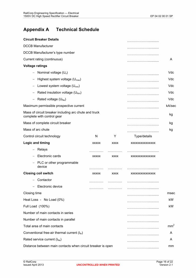
11.3 Information to be Provided The information listed in the attached Technical Schedule at Appendix A shall be maintained for each circuit breaker.
RailCorp Engineering Specification — Electrical 1500V DC High Speed Rectifier Circuit Breaker EP 04 02 00 01 SP
© RailCorp Page 16 of 22 Issued April 2013 UNCONTROLLED WHEN PRINTED Version 2.1
Appendix A Technical Schedule
Circuit Breaker Details .………………............
DCCB Manufacturer .………………............
DCCB Manufacturer’s type number .………………............
Current rating (continuous) .………………............ A
Voltage ratings
− Nominal voltage (Un) .………………............ Vdc
− Highest system voltage (Umax) .………………............ Vdc
− Lowest system voltage (Umin) .………………............ Vdc
− Rated insulation voltage (UNm) .………………............ Vdc
− Rated voltage (UNe) .………………............ Vdc
Maximum permissible prospective current .………………............ kA/sec
Mass of circuit breaker including arc chute and truck complete with control gear
.………………............ kg
Mass of complete circuit breaker .………………............ kg
Mass of arc chute .………………............ kg
Control circuit technology N Y Type/details
Logic and timing xxxxx xxxx xxxxxxxxxxxxxxx
− Relays .………… .………… .………………............
− Electronic cards xxxxx xxxx xxxxxxxxxxxxxxx
− PLC or other programmable device .………… .………… .………………............
Closing coil switch xxxxx xxxx xxxxxxxxxxxxxxx
− Contactor .………… .………… .………………............
− Electronic device .………… .………… .………………............
Closing time .………………............ msec
Heat Loss - No Load (0%) .………………............ kW
Full Load (100%) .………………............ kW
Number of main contacts in series .………………............
Number of main contacts in parallel .………………............
Total area of main contacts .………………............ mm2
Conventional free-air thermal current (Ith) .………………............ A
Rated service current (INe) .………………............ A
Distance between main contacts when circuit breaker is open .………………............ mm
RailCorp Engineering Specification — Electrical 1500V DC High Speed Rectifier Circuit Breaker EP 04 02 00 01 SP
© RailCorp Page 17 of 22 Issued April 2013 UNCONTROLLED WHEN PRINTED Version 2.1
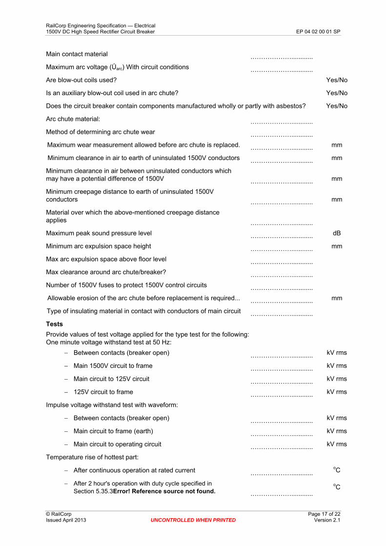
Main contact material .………………............
Maximum arc voltage (Ǘarc) With circuit conditions .………………............
Are blow-out coils used? Yes/No
Is an auxiliary blow-out coil used in arc chute? Yes/No
Does the circuit breaker contain components manufactured wholly or partly with asbestos? Yes/No
Arc chute material: .………………............
Method of determining arc chute wear .………………............
Maximum wear measurement allowed before arc chute is replaced. .………………............ mm
Minimum clearance in air to earth of uninsulated 1500V conductors .………………............ mm
Minimum clearance in air between uninsulated conductors which may have a potential difference of 1500V .………………............ mm
Minimum creepage distance to earth of uninsulated 1500V conductors .………………............ mm
Material over which the above-mentioned creepage distance applies .………………............
Maximum peak sound pressure level .………………............ dB
Minimum arc expulsion space height .………………............ mm
Max arc expulsion space above floor level .………………............
Max clearance around arc chute/breaker? .………………............
Number of 1500V fuses to protect 1500V control circuits .………………............
Allowable erosion of the arc chute before replacement is required... .………………............ mm
Type of insulating material in contact with conductors of main circuit .………………............
Tests Provide values of test voltage applied for the type test for the following: One minute voltage withstand test at 50 Hz:
− Between contacts (breaker open) .………………............ kV rms
− Main 1500V circuit to frame .………………............ kV rms
− Main circuit to 125V circuit .………………............ kV rms
− 125V circuit to frame .………………............ kV rms
Impulse voltage withstand test with waveform:
− Between contacts (breaker open) .………………............ kV rms
− Main circuit to frame (earth) .………………............ kV rms
− Main circuit to operating circuit .………………............ kV rms
Temperature rise of hottest part:
− After continuous operation at rated current .………………............ oC
− After 2 hour's operation with duty cycle specified in Section 5.35.3Error! Reference source not found. .………………............
oC
RailCorp Engineering Specification — Electrical 1500V DC High Speed Rectifier Circuit Breaker EP 04 02 00 01 SP
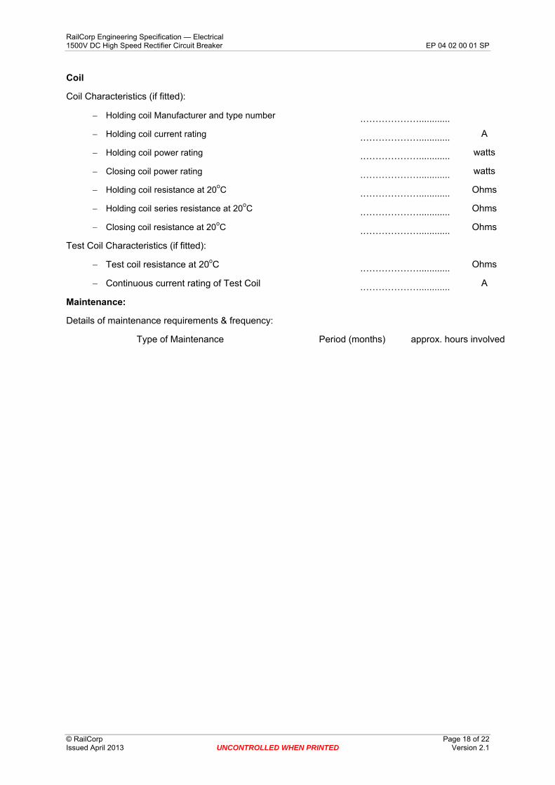
Coil
Coil Characteristics (if fitted):
− Holding coil Manufacturer and type number .………………............
− Holding coil current rating .………………............ A
− Holding coil power rating .………………............ watts
− Closing coil power rating .………………............ watts
− Holding coil resistance at 20oC .………………............ Ohms
− Holding coil series resistance at 20oC .………………............ Ohms
− Closing coil resistance at 20oC .………………............ Ohms
Test Coil Characteristics (if fitted):
− Test coil resistance at 20oC .………………............ Ohms
− Continuous current rating of Test Coil .………………............ A
Maintenance:
Details of maintenance requirements & frequency:
Type of Maintenance Period (months) approx. hours involved
© RailCorp Page 18 of 22 Issued April 2013 UNCONTROLLED WHEN PRINTED Version 2.1
RailCorp Engineering Specification — Electrical 1500V DC High Speed Rectifier Circuit Breaker EP 04 02 00 01 SP
© RailCorp Page 19 of 22 Issued April 2013 UNCONTROLLED WHEN PRINTED Version 2.1
Appendix B Request for Tender Checklist Application
The following material is for guidance in the preparation of a Request for Tender for this type of equipment. This checklist itself is not intended to directly form part of any contract.
This section to be read in conjunction with the RFT Checklist in specification EP 00 00 00 15 SP Common Requirements for Electric Power Equipment.
The RFT is to include a statement that all standards and specifications are subject to revision, and parties to agreements based on this specification are required to apply requirements of the most recent editions.
Information to be supplied to the Tenderer
Where this document is used as the basis for procurement of equipment for a particular location, in addition to the general requirements in this standard the following information related to the particular site will need to be supplied:
Requirements for specific deliverable’s including:
• Spare contacts. • Spare fuses. • Racking Handles • Operating Handles
Number of circuit breakers required.
Information to be Sought From the Tenderer
• Integrated Support information in accordance with RailCorp Standard • Tenders to complete and submit Technical Schedule in Schedule A • Provision of general arrangement and sectional elevations of circuit breaker
showing overall dimensions, required space for removing arc chute, required space to insulated and/or earth parts,.
• Schematic diagram • Characteristics of the circuit breaker (i2t or break time) of circuit breaker • Oscillographic records showing circuit breaker performance under the interrupting
conditions
RailCorp Engineering Specification — Electrical 1500V DC High Speed Rectifier Circuit Breaker EP 04 02 00 01 SP
© RailCorp Page 20 of 22 Issued April 2013 UNCONTROLLED WHEN PRINTED Version 2.1
Appendix C Requirements for Technical Aspects of Tender Evaluation
Evaluation of tenders
Tender submissions will be evaluated based on a number of criteria. One constant criterion is compliance with this specification. The Chief Engineer Electrical requires that persons evaluating the technical aspects of this tender have sufficient technical competence for the task.
Tender evaluation committees shall forward details of persons evaluating the technical aspects of the tender to the Chief Engineer Electrical for concurrence. This will normally be in the form of an email and is to include sufficient detail of the tender and the person to enable the Chief Engineer Electrical to satisfy themself of the merits of the evaluating person. A minimum of 4 weeks notice is required prior to the evaluation of the Tenders.
The Chief Engineer Electrical will advise within 5 working days only if the person is considered technically unsuitable for the technical evaluation.
Acceptance of product
A number of the specifications require acceptance of product at both the factory and at site. The purchaser is to advise the Chief Engineer Electrical the details of the person carrying out the acceptance testing for the concurrence of the Chief Engineer Electrical. A minimum of 4 weeks notice is required prior to the evaluation of the acceptance testing.
The Chief Engineer Electrical will advise only if the person is considered unsuitable for the acceptance testing.
The Chief Engineer Electrical reserves the right to nominate a representative to review and/or attend such acceptance.
Record Keeping
Where product is purchased against this specification, the Chief Engineer Electrical requires that relevant detail be provided so that it can be logged against this specification.
For RailCorp purchases, all records are recorded in Ariba.
Where this specification is utilised by parties external to RailCorp (Alliance parties, etc) then copies of all relevant technical information and evaluation shall be forwarded to the Chief Engineer Electrical for filing against the specification. In addition copies of selected commercial information pertaining to the ongoing support of the product as follows is also required.
• Warranty details • Spare parts and associated availability • Product support information.
RailCorp Engineering Specification — Electrical 1500V DC High Speed Rectifier Circuit Breaker EP 04 02 00 01 SP
© RailCorp Page 21 of 22 Issued April 2013 UNCONTROLLED WHEN PRINTED Version 2.1
Appendix D RailCorp Standard Type Tests Mechanical and Endurance Tests Repeatability of the Trip Current Value
The tests described in Section 9.3 shall be carried out before the Mechanical & Endurance Tests of this section and at the completion of these Tests. In both cases the actual trip current shall not deviate from the set value by more than ±5%.
Mechanical Operation Test
The following shall be proved:-
Satisfactory tripping of the circuit breaker with the closing device energised.
Satisfactory behaviour of the circuit breaker when the closing operation is initiated with the tripping device actuated.
Mechanical Endurance Test
The circuit breaker shall undergo 1500 operating cycles consisting of a closing operation followed by an opening operation. This test shall be carried out at a minimum rate of 10 cycles per hour. The test may be carried out without current in the main circuit of the circuit breaker. No adjustment or maintenance is to be carried out on the circuit breaker for the duration of the test.
Electrical Endurance Test
The circuit breaker shall undergo 500 operating cycles consisting of a making operation followed by a breaking operation of its continuous rated current at its operational voltage. The minimum number of operating cycles shall be 10 cycles per hour with the circuit breaker to remain closed for a maximum of 2 seconds. No adjustment or maintenance is to be carried out on the circuit breaker for the duration of the test.
The circuit breaker must not fail to open or close during this test.
Ability to Withstand Short Circuit
With a prospective current of 75kA @ 6000kA/sec initial rate of rise, the ability to withstand a short circuit test is considered to have been passed if the fault is applied to the closed circuit breaker and it trips.
Temperature Rise Tests Cyclic Loading Test
The circuit breaker shall be operated at 100% of the full load current until the temperature stabilises. Each of the overloads specified in Section 5.3 shall then be applied. The equipment shall be stabilised at the 100% of full load between the applications of each overload.
The temperature rise of the various parts shall not exceed the values in the Technical Schedule at Appendix A.
This test may be carried out with the test current in the main circuit applied at a low voltage.
RailCorp Engineering Specification — Electrical 1500V DC High Speed Rectifier Circuit Breaker EP 04 02 00 01 SP
© RailCorp Page 22 of 22 Issued April 2013 UNCONTROLLED WHEN PRINTED Version 2.1
Continuous Current Test
The circuit breaker shall carry 4000A dc for a period of time sufficient for the temperature rise of all parts to become constant (rate of change less than 1oC per hour). The temperature rise of the various parts shall not exceed the values in the Technical Schedule at Appendix A.
This test may be carried out with the test current in the main circuit applied at a low voltage.