Embed Size (px)
Citation preview
1565-B SERIES
Sound-LevelMeter
User and Service Manual
♦ PRECISION INSTRUMENTS FOR TEST AND MEASUREMENT ♦
Copyright © 2001 IET Labs, Inc.
1565-B im/January, 2002
LOW (NO Of IOU~ lt:VU R.AMtt u 1 av uvu. "AH<il (;OHT-
-10 .... lPOM.ottOr JICAU f()fll JOU!IfO UV(l C0MPARISI0'4 ()I'll 'l ~GU
(AliiA.ATION AOJUSTMtNl OOOLSUI'PLI£01
DtPR(S$ TOSEl£C1 W(IGHfiNO N[~l(
WICR~£
flHSTAU.. AGR ¥tlNOSICfUlN P'N 1510-11521 TO IIIlA I(( OUTOOOIIlii!USUJlUI(IifJS IHMUlNtl Of WI.,_O
UVfLRAHQ( CON"lft()t LOCK
Mnt.A Sf'f£1)-o()()WN FOR SlOW ... f04' FAST
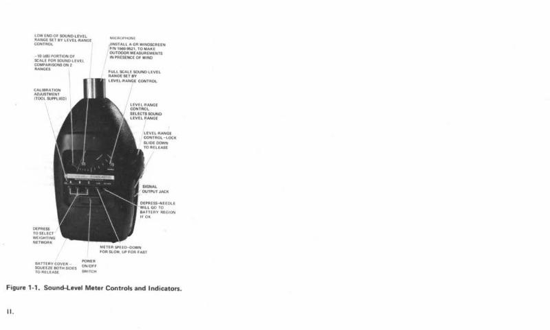
Figure 1-1. Soun~evel Meter Controls and Indicators.
II .
8030-1631
8120.{)150(2)~, i SlR
52104109 ~I 7550-1745
54
~~~~~c~. 19844750
RESISTANCt IS IN OHMS. K = 103 M = 106
CAPACITANCE 1$ IN FARADS,"' • 10'6 p = 10" 1 1
VOLTAGES t XPLAINED IN INSTRUCTION BOOK SERVICE NOTES c==:::::J =PANEL CONTROL r:::::::J =REAR CONTROL 0 =SCREWDRIVER CONTROL WT =WIRE TIE TP =TEST POINT COMPLETE REFERENCE DESIGNATION INCLUDES SUBASSEMBLY LETTER C Rl B Rl ETC
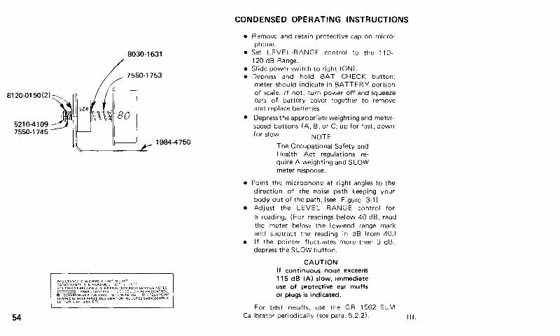
CONDENSED OPERATING INSTRUCTIONS
• Remove and retain protective cap on microphone.
• Set LEVEL-RANGE control to the 110-120 dB Range.
• Slide power switch to right (ON). • Depress and hold BAT CHECK button;
meter should indicate in BATTERY portion of scale. If not, turn power off and squeeze ears of battery cover together to remove and replace batteries.
• Depress the appropriate weighting and meterspeed buttons (A, B, or C; up for fast, down for slow NOTE
The Occupational Safety and Health Act regulations require A weighting and SLOW meter response.
• Point the microphone at right angles to the direction of the noise path keeping your body out of the path, (see Figure 3-1 ).
• Adjust the LEVEL RANGE control for a reading_ (For readings below 40 dB, read the meter below the I ow-end range mark and subtract the reading in dB from 40.)
• If the pointer fluctuates more than 3 dB, depress the SLOW button.
CAUTION If continuous noise exceeds 115 dB (A) slow, immediate use of protective ear muffs or plugs is indicated.
For best results, use the GR 1562 SLM Calibrator periodically (see para. 5.2.2). Ill.
IV.
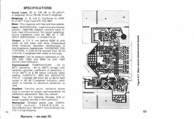
SPECIFICATIONS Sound Level : 30 to 130 dB re 20 JAN/m2
,
A weighted: 35 to 130 dB, Band C weighted. Weighting: A. B. and C. Conforms to ANSI S1 .4-1971 Type 2and IEC 123.1961. Meter: Rms response with fast and slow speeds. Input: MICROPHONE: Lead-zirconate-titanate ceramic. 1560-P96 Adaptor converts input to 3-pin male A3 connector; for correct weighting, source impedance must be 380 pF j; 5%. INPUT IMPEDANCE: "' 13 Mfl//15 pF. Output: ;.. 1.2 V rms behind 6200 n with meter at full scale; will drive Octave·Band Noise Analyzer. recorders, oscilloscopes, or low-impedance headphones. HARMONIC DIS· TORTION : <; 0.5% (0.1% typical) from 32Hz to 8 kHz. C-weighted with meter at full scale. Calibration: Can be pressure calibrated at 1 25. 250. 500. 1000, and 2000 Hz with 1562 Sound-Level Calibrator. Environmental: TEMPERATURE: -10 to so•c operating: - 40 to +60"C storage, with batteries removed; coefficient of sensitivity "' +0.02 dBfC at 6 dB below full-scale meter reading. HUMIDITY: 90% RH . MAGNETIC FIELD: 1·0ersted (80 A/m) 50· or 60·Hz field causes "' 45 dB C-weighted Indication when meter is oriented to maximum sensitivity to field. Supplied: Carrying pouch. miniature phone plug to connect to output, and screwdriver for calibration adjustment. Also. hex wrench. Power: Two 9.V batteries (Burgess 2U6 or equal) supplied. provide"' 50-h operation. Mechanical : Shielded plastic case. DIMEN· SIONS (wxhxd) : 3.63x6.5x2 .09 in . (92x165x53 mm). WEIGHT:13oz(0.45 kg) net, 3 lb ( 1.4 kg) shipping.
Warranty - see page 30.
• .~
.t: e l f .t: i! .!1 u c
i ,.: til ! .t II.
53
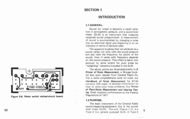
Figure 5-6. Meter switch etched-circuit board.
52
SECTION 1
INTRODUCTION
1.1 GENERAL.
Sound (or noise) is basically a rapid varia· tion in atmospheric pressure, and a sound-level meter (SLM) is an instrument that measures weighted sound pressure-level. A measurement of sound is accomplished by changing a noise into an electrical signal and displaying it on an indicator in terms of decibels (dB).
The apparent loudness that we attribute to a sound varies not only with the sound pressure but also with the frequency (or pitch) of the sound. How it varies with frequency depends on the sound pressure. This effect is taken into account to some extent for pure tones by "weighting" networks included in the SLM.
The above points are illustrated briefly in A Primer of Noise Measurement , a 34-page book· let free upon request from General Radio Co. For a more comprehensive work on noise, our Handbook o f Noise Measurement for $7.50 contains 328 pages of detailed information on how to solve your noise problems. Our Primer of Plant·Noise Measurement and He;uing Test· ing (free) explains conformance to the Federal Regulations of 1971.
1.2 PURPOSE.
The basic instrument of the General Radio sound-measuring·equipment line is the sound· level meter (SLM). The unit (Figure 1·1), is a Type 2 !i.e. general purpose) SLM. A Type 2 1
instrument has tolerances required by the A mer· ican National Standards Institute (ANSI) stand· ard specification S1.4·1971 for sound level meters. These tolerances are generally more stringent than those required for Type 3 in· struments.
The chief use of the SLM is making noise measurements in a working or living environ· ment such as: routine measurements of office· building ventilator systems. typewriters. machinery. traffic noise. and other noises of a reasonably con.stant character.
1.3 DESCRIPTION. 1.3.1 G-r81.
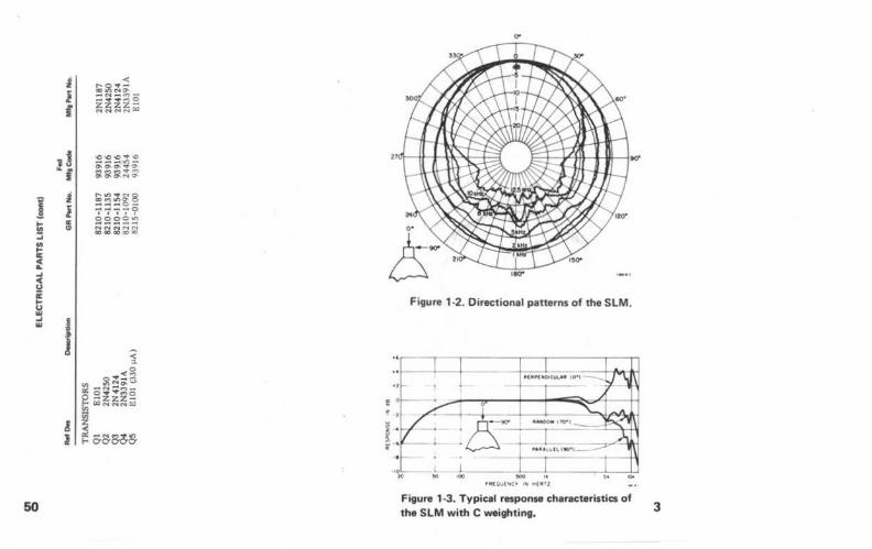
The instrument is housed in a high impact molded plastic case that Is shaped for comfort· able hand·hcld operation and tapered at the microphone end to minimize the effect of case diffraction. It consists of the following elements: a microphone to pick up sound; an amplifier. to raise the microphone output to useful levels; a calibrated attenuator. to adjust the amplification to a value appropriate to the sound level being measured; an Indicating me· ter, to exhibit the measured sound level: net· works. to adjust the frequency characteristic of the response (A. B. or C weighting); and an output connection, to accommodate additional measuring equipment. It covers the sound-level range from 30 to 130 dB above the standard reference level of 20 ~o~N/m2 (0.0002 ~o~barl. Figure 1·2 shows a polar plot of the angle-of· incidence responses and Figure 1·3 shows the frequency response as a function of incidence
2 of the SLM.
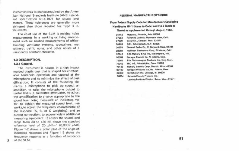
FEDERAL MANUFACTURER'S CODE
From Federal Supply Code lot Mllnufac:turtn C.tlloging
H.ndbookJ H4-1 (Name to Code) end H4-2 (Code to
Name) as supplementiMI through August, 1968.
~713 MotO<olo, Pt~o~N•. Ariz. 85008 07263 Foifchlld C.mlnl, Mounqln View, C.UI. 07999 11o<g Inti., ONwn. Wltc. 631111
24446 G.E., ~18dv. N.Y. 12306 24656 GIMral Rodlo Co. W. eon-d.-· 01781
28958 Hoff,..n EIKt<onlco Corp, El Monte, 01111. 37942 P.R. Mollory a Co Inc, lndi~. Ind.
56288 Spregue Eloetnc Co, N. Adlmo, - · 72982 Erl<o Tlchnoloeootl Producu Inc, Eno, ....,n.
75042 IRC 1~. Philodllplllo, ..... n . 11108 761 49 Mollory Electric Corp, OotrOtt, Mich. 48204 80183 ~ Producu Co. No. Adem&.-· 82389 Switchc:rolt Inc, Chlcogo,lll . 60630
56854 9\'1..,..1<1 Elocttlc Products Inc.,
Ugluing l'roduoll Di•ltlon, Solom. - .. 011171
51
I !ii ...
~ ... <( u i
~ ... "'
50
i l f
1! '"f
l l .. "
< ~~~~ -c....-M--••t"")O ~~~~~
'<)>0'()~..0 ___ .,_ ~o.o.•a. M~(O')<It"M o. o.o.c••• o-
~~~§~ ----o I I Itt
ggs2~ NNNNN GOGOGO OOCIO
Figure 1 ·2. Directiona l patterns of the SLM.
Figure 1 ·3. Typical response characteristics of the SLM with C weighting. 3
4
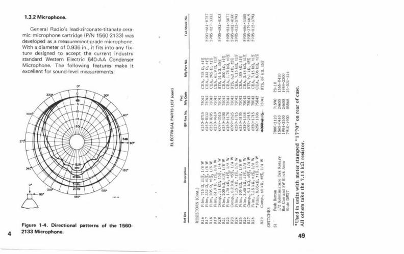
1.3.2 Microphone.
General Radio's lead-zirconete-titanate cera· mic microphone cartridge (P/N 1560·2133) was developed as a measurement-grade microphone. With a diameter of 0.936 in., it fits into any fixture designed to accept the current industry standard Western Electric 640-AA Condenser Microphone. The following features make it excellent for sound-level measurements:
Figure 1-4. DirectioMI pattet'ns of the 1560-2133 Microphone.
-::>
j t; :::; ~ a: < ... ..J < <> a: .... <> w ..J w
! l i
1~ ~-I
! ! c ..
1 ~
J
...... 8 "'8 ... .,..., ..... .,. 8-7-~7 7 7' 7 _,..
N ..... ., '8!:: ~ ~~; ,:,8 8 ~§§ ~.,. .,. "'"' "' "'"'"'
¥')::;)'..., ,. -o-....,~,....
7 7 7 .0"' "' ~ .... -N<>O
888 ,. .,. .,. ''" '""
.; :a u .... 0 .. .. ~ c 0
0 f...
49
• ;eg :0? .... (0') ,..,_ .,..0' z ~~
;0<() ..... ,...
I 7-:"'?e;' 00 N i0.t")V") .. :;;~ r-oo-
N>OOO 1 88 8~88 ...
"'"' o-c>o.o.
""" ..,,,,.,.,.,
"""""" ~ .... '* to '*"""" i
-;;;;; .. fl(w .. ;;.: aac ... ~:;; o'!l .•. l )( 2::1:,; c:: •• ~ ·C~~ ~ ... c::c:: ... ...N ,... 0~0' NC: .Jot<O.n >O
f ~ ::t' =~~~~ • .:.t ·-N ~ ... -....
:l NO:N""'N ... <<cQW< ·< §. ·<<< co ~ !;; ., tiUI)tll~t:QelAJ ~~"'""''
I :::> ... UOU a.. U U N 0()0
1j 1(! g; § NNNoONNN ~NN<"'NN ~~~~~~<5 ~ ... 3(!;~
!!! f I:! l:l ;'.?~~8;!?)!:?~ 0~~1!?~1!? ... 0 00 ... t! ! s 0 .,
~~~~~~" S""W')..otn.o Cit ~
,..._N_N <( l ~~;;; ;;;~~ NNO.Nr-N ... r;- 0 ~7~~-;"~ ... c .... ~ 0 000.!.00..0
§§§~~~ ~ " ..,
::? ~~~~~~~ . ,.. ii "' . "' ti a "' ... ... "' .:
H!~ ~ ~~~~~ ~~~~! 3 C ~~~~:;
1 e -:-:~-:.:::-!~~ ::> tJII(flt( - !1( .. "--a::
""~"""""" ~ )( • :;;:;; "..'!1~-:""i J ~
.,. c: ~+4:;;;;: .., i aaic:.._W:;8 ~ss~~ 5 ~ ::;::~:,..,;s .c;~ u .. E ~~=~~:;;~ ~ ..... ~.011').0 5 co 0 .. Na-N-:~
"' < u :::> 2 ("')II) ·- - ·•i • N,....N
0 .. .. e e t e e t e ,~He e e d !l E a.
" ~ < {: ::; ~~81i:~8~l;;88ii:;;:;;: "' ~ "' a:
A 0 l2 "' "' ... § ~ u "' "' -NM•II)
i .. ;~2C2~~:!~ 5 ~ ::1: ::; a: 22222
48
. LL.~ .. ~ . ..,._~tt.eot'fX- [\
. I IIIMIIIOIII ·I• t•N.!. t{ \
• ......l CIIIMACtlllllTIC~
I ll ~ 1'-il\ . I I I I 1' t- r.;
• .. I ~-==-~Y- 1\\ . I ~ I I I I . I 1(.......-.:l. I I I I \
I I I I I I ... .. .... ._
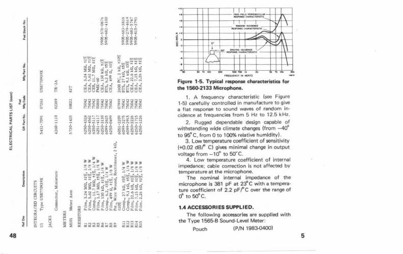
Figure 1·5. Typical response characteristics fOf' the 1560-2133 Microphone .
1. A frequency characteristic (see Figure 1 ·5) carefully controlled in manufacture to give a flat response to sound waves of random incidence at frequencies from 5 Hz to 12.5 kHz.
2. Rugged dependable design capable of withstanding wide climate changes (from - 40° to 95"C, from 0 to 100% relative humidity) .
3. Low temperature coefficient of sensitivity (-+0.02 dBf C) gives minimal change in output voltage from - 10° to SOY C .
4. Low temperature coefficient of internal impedance; cable correction is not affected by temperature at the microphone.
The nominal internal impedance of the microphone is 381 pF at 2:fC with a tempera· ture coefficient of 2.2 pFfC over the range of 0° to 50°C.
1.4 ACCESSORIES SUPPLIED.
The following accessories are supplied with the Type 1 565-B Sound-Level Meter:
Pouch (P/ N 1983-0400) 5
6
Screwdriver Micro Plug
Two bat1erles
Allen wrench 1.050-in.)
(P/N 1565.()44()) ($witchcraft 850-P2)
(Burgess 2U6 or equal)
(P/N 7985·1680)
1.5 ACCESSORIES AVAILABLE. Following are some of the aooessories that
are available for use with the SLM (consult the GR catalog information for others) :
1. Type 1562 Sound-Level Calibrator (P/N 1562-9701) for accurate field calibrat ion of microphones and sound-measuring instruments.
2. Type 1560·P96 Adaptor (P/N 1560-9696) to adapt the input socket to mate with a stand· ard, 3 terminal, male, aud o connector (Switchcraft Type A3M) for connection to a vibration pickup or other t ransducer.
3. Type 1560-P52 Vibration Pickup (P/N 1560·9652) (refer to para. 2 .2).
4. Type 1560-P83 Earphone Coupler (P/N 1560-9683) for connecting an audiometer earphone to the SLM.
5. Type 1560-P73 Extension Cable (P/N 1560-9673), for use between the microphone and instrument input (25ft).
6 . Adaptor cables: Type1560·P77, Micro plug to 3/4-in. spaced banana plug pair (GR274) (P/N 1560-9677); Type 1560·P78, Micro plug to std. %-in. phone plug (P/N 1560-9678); Type 1560-P79, Micro plug to BNC (P/N 1560-9679); Type 1560·P80, Micro plug to std . 1/4 -in. phone jack (P/N 1560-9680).
7. Type 1560-9590 Tripod. 8. GR Microphone Windscreen (P/N 1560-
9521) for reducing the effects of wind noise and protucting the diaphragm.
l l "' "
5 §~
~ u
47
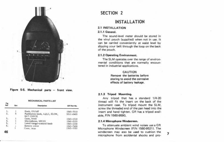
Figure 6-5. Mechenic:el parts - front view.
MECHANICAL PARTS LIST At Rot O.t - 011-No.
I. I Knob, ON/off 1565-1310 2. s Pu.thhutton knob, A,B,C, SLOW, 5511.04()3
BATCHEC!> 3. C.•e, fronr 1565-1510 .. Mlcropbone, MK 101 1560·2133 5. Level-range-control knob 1565-1230 6. Battery cover 1565-7.:10
Cue. rear 1565-SOIO
46
SECTION 2
INSTALLATION 2.1 INSTALLATION 2.1.1 General.
The sound·level meter should be stored in the vinyl pouch (supplied) when not in use. It can be carried conveniently at waist level by slipping your belt through the loop on the back of t he pouch.
2.1 .2 Opereting Environment. The SLM operates over the range of environ·
mental conditions that are normally encoun· tered In industrial applications.
CAUTION Remove the ban eries before storing to avoid t he corrosive effects of banery leakage.
2.1.3 Tripod Mounting. Any tripod that has a standard 1 /4·20
t hread will fit the insert on the back of the instrument case. To tripod mount the SLM, screw the threaded end of the pan head into the insert and hand tighten. GR has a tripod avail · able, P/N 1560-9590.
2.1 .4 Mic:rophone Windlcreen . To attenuate ambient wind noises use a GR
Microphone Windscreen IP/N 1560-9521). The windscreen may also be used to cushion the microphone from accidental shocks and pro· 7
8
teet the microphone diaphram from accumulations of oil, vapor and dust
The windscreen is a 3-in diameter sphere that fits snugly over the microphone. It is made of reticulated polyurethane foam and can be conveniently removed and washed, or replaced, if it becomes soiled. This is in addition to the obvious advantage of attenuating ambient wind noises. such as might emanate from a fan blowing cooling air across the site of the microphone (see Figure 2-1al.
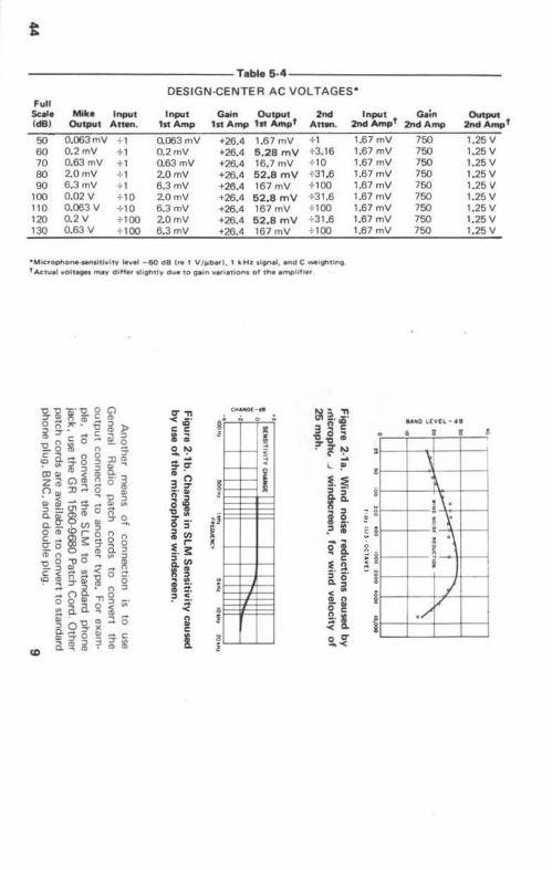
Any attenuation of monitored noise resulting from use of the windscreen occurs over only a portion of the frequency spectrum being monitored. The loss of system sensitivity oc· casioned by use of the windscreen is shown in Figure 2·1b. For normally encountered noises, the influence of the windscreen on measured sound level is negl igible.
2.1.5 Output Connector.
It may be desirable to drive other equipment with the SLM, such as a recorder or an oscilloscope. Therefore, a connector, near the level-range control. is available to supply voltages proportional to the meter response. A Switchcraft Type 850-P2 (Micro-plug) connec· tor is supplied with the SLM to complete this end of a patch cord. The other end can be terminated with whatever connection is necessary. The output voltage is "" 1.2 V for a full-scale reading into an open circuit, with a 620().11 source impedance.
LDLDLDLDLDLDLDLD o ~LI'iLI'i<Or-:r-:a;o.r 10 <t (') (') (') (') (') (') <t <t
LDLDLD LDLD<t ~ in~~~~~~g~
LDLD LDLD
i ~m~:li[{;mf82<b LD LD
R!i5~~!;5~~$;:: LDLD LD
omoo<O<O<OLD<tM (X),....,....,....,....,....,....,....,....
LD LDLD
~m~:Bl8<b~f1i~
LDLD LDLD
~r:$ll:lli5!i5~$$ LD LD LDLD
<toa:><O<aLI'i<tNN CX)CX),.._,....,....,....,....,....,....
... .. .tl
~ >
Gl c 0 .J:. Q. 0
~ E Ill '0 0 <D I
45
t
Teble 5-4
DESIGN-CENTER AC VOL TAGEs• Full
Scale Mille Input Input Gain Output 2nd (dB) Output Anen. 1nAmp 1n Amp 111 Ampt An .....
50 0.063mV + 1 0.063mV +26.4 1.67mV +1 60 0.2mV +1 0.2mV +26.4 6.28 mV +3.16 70 0.63 mV +1 0.63 mV +26.4 16.7mV +10 80 20mV + 1 20mV +26.4 62.8 mV +31.6 90 6.3mV +1 6.3mV +26.4 167mV +100
100 0.02V +10 20mV +26.4 62.8 mV +31.6 110 0.063V +10 6.3mV +26.4 167mV +100 120 0.2V + 100 20mV +26.4 52.8 mV +31.6 130 0.63 V + 100 6.3mV +26.4 167mV +100
•Mic:tophone-wnthlvhv tevet -&0 d8 (re 1 V/ ,.,IHI), 1 kHa tlontl. •n<l C wetflhtfng t Acw•l \'Oh....- m.v differ .tightlY due 10 ~in vetietiont of tlw •mphf .. ,
-g. i ~ .. 2. g Cl o(j~!D-n> i::r· .. -g~)> "2.8$o- i5 c ~ n -~~;.8g:JJ~ (DG.J(D~ ~~ .., z c; Cl :6 ~ -· =l n ::o:l .. oili ~~-,_. Q'C~ j -·<J1:r- d) ut a.-m~ o -a.~OVl~»g. o o~<br:::l -§.gS3~~8n <Dno ~ag "0 o ~o..,"" ~ s~~ .. <-~ · 3::r6ti
0B
.. n&·n:::l oo~»Tio "' a. a o ~ ... m. .., ft)
5.9-g.~:lO ~:rom-e
<Q a.~i~~!S
fTTI < C'' c: c: ;; 0 !'.) -. ..... ;~ 3 Q (;"I» a.! -o .. iS~. i ~ ~ r -· ~ a.~ 1'1 :I
i ~· ~ <~
. ~·
!;: c:
l
- ·· ~· I
II I l §
:i
~
i & !
3 l
!)!~. ~ 3
.,co .. c: -o 0 .. ::r -o .. . iS~
:I ... .. !"
~:E :I - · a. :::I 1'1 a.
i 2. .:::1 l£ 0'" .. :!. ~ ~ -· .. :I - · Q.O
:I < .. !.~ g c:
~· l orr -<
Input Gain 2nd Ampf 2nd Amp
1.67 mV 1.67 mV 1.67mV 1.67mV 1.67mV 1.67mV 1.67mV 1.67 mV 1.67mV
9
:
' : i 8
~ :
:
i ! I
i
750 750 750 750 750 750 750 750 750
aAJCO U \'lL. • •I
6 3 I I I
_1 ~ %\ .
F~ = • ~ ~-i
J v
. /
Output 2nd Ampt
1.25V 1.25V 1.25V 1.25 v 1.25 v 1.25V 1.25 v 1.25V 1.25 v
I
I
I - ,
J
10
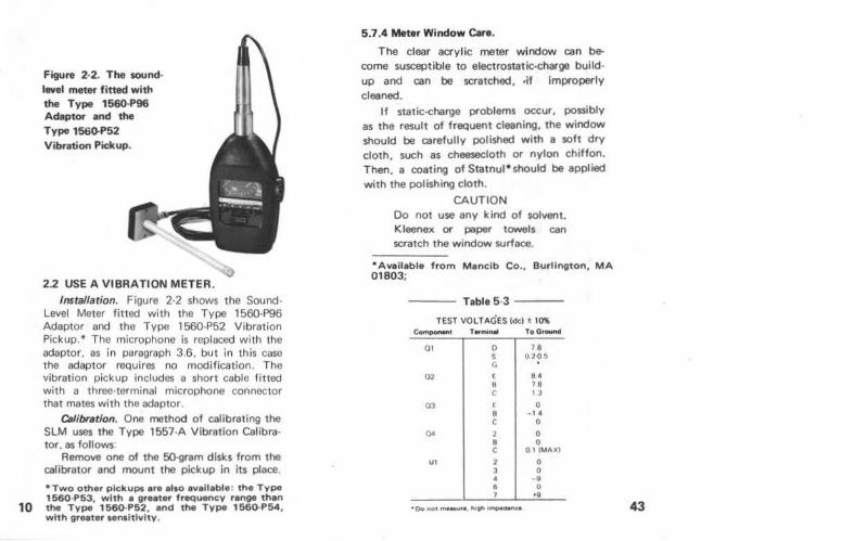
Figure 2·2. The sound· level meter fitted with the Type 1560-P96 Adaptor and the Type 156<H'52 Vibration Pickup.
2.2 USE A VIBRATION METER.
Installation. Figure 2·2 shows the SoundLevel Meter fitted with the Type 1560·P96 Adaptor and the Type 1 560-P52 Vibration Pickup. • The microphone is replaced with the adaptor, as in paragraph 3.6. but in this case the adaptor requires no modification. The vibration pickup includes a short cable fitted with a three-terminal microphone connector that mates with the adaptor.
Clllibrstion. One method of calibrating the SLM uses the Type 1557-A Vibration Calibrator. as follows:
Remove one of the 50-gram disks from the calibrator and mount the pickup in its place.
•Two other pickups ere also available: the Type 1 560-P53, with • greater frequenc;y range than the Type 1560-P52, and the Type 1560-P54, with greater senaltlvlty.
5.7.4 Meter Window Care.
The clear acrylic meter window can become susceptible to electrostatic-charge buildup and can be scratched, ·if improperly cleaned.
If static-charge problems occur, possibly as the result of freQuent cleaning, the window should be carefully polished with a soft dry cloth, such as cheesecloth or nylon chiffon. Then, a coating of Statnul *should be applied with the polishing cloth.
CAUTION Do not use any kind of solvent. Kleenex or paper towels can scratch the window surface.
• Available from Maneib Co .. Burlington, MA 01803;
Table 5·3 --
TEST VOLTAGES (del t 10% COfnP<M*"'I TtfmiMII ToO-
01 0 18 s 020~ G
02 E e• B 78 c 1 3
03 ( 0 8 - 1· c 0
00 2 0 8 0 c OIIMAXI
U1 2 0 3 0 • g e 0
' •8
43
42
ies. Replace them with fresh units if the check doesn't give an ind icat ion in the BATTERY region.
5.7.2 Electr~ Chedc. Next, Isolate the problem to either the
microphone or the rest of the instrument. To do this, replace the microphone with its equivalent impedance (para. 5.2.3) and drive the Input with a 0.63 v, 1-kHz signal. Check the SLM indication to be 130 ± 3 dB. I f this indication Is satisfactory, the microphone is defective and should be replaced. If it is not satisfactory, use the DVM to check the voltage at the output jack. It should be> 1.25 V. If this voltage is in· correct. use Tables 5-3 and 5-4 to further iso· late the problem.
5.7.31nt.mal Noite.
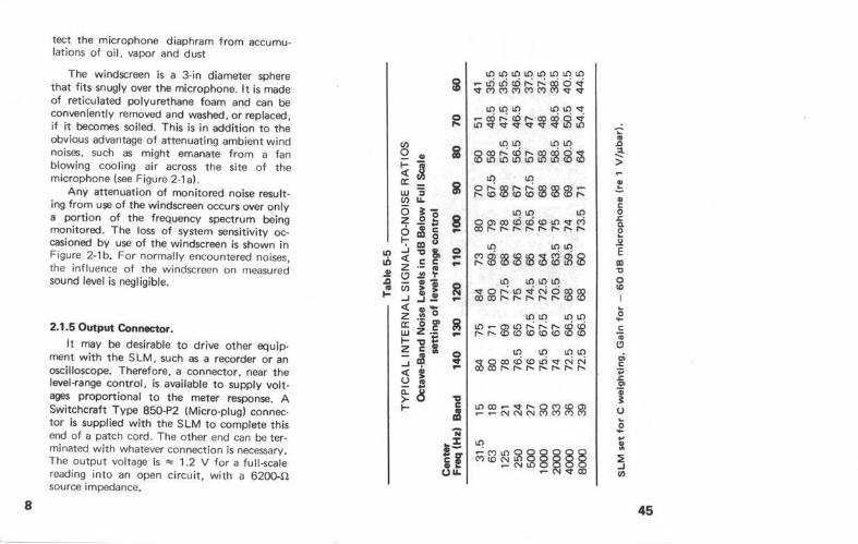
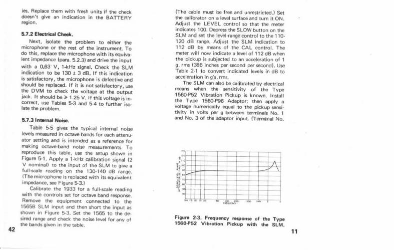
Table 5-5 gives the typical internal noise levels measured in octave bands for each attenu· ator setting and is intended as a reference for making octave-band noise measurements. To reproduce this table, use the setup shown in Figure 5-1. Apply a 1-kHz calibration signal (2 V nominal) to the input of the SLM to give a full -scale reading on the 130.140 dB range. (The microphone is replaced with its equivalent impedance. see Figure 5-3.)
Calibrate the 1933 for a full-scale reading with the controls set for octave band response. Remove the equipment connected to the 15658 SLM input and then short the input as shown in Figure 5-3. Set the 1565 to the de· sired range and check the noise level for any of the bands given in the table.
(The cable must be free and unrestricted.) Set the calibrator on a level surface and turn it ON. Adjust the LEVEL control so that the meter indicates 100. Oepress the SLOW button on the SLM and set the level-ra~ control to the 1 10-120 dB range. Adjust the SLM indication to 112 dB by means of the CAL control. The meter will now indicate a level of 112 dB when the pickup Is subjected to an acceleration of 1 g, rrns (386 inches per second per second). Use Table 2-1 to convert indicated levels in dB to acceleration In g's, rms.
The SLM can also be calibrated by electrical means when the sensitivity of the Type 1560-P52 Vibration Pickup is known. Install the Type 1560-P96 Adaptor; then apply a voltage numerically equal to the pickup sensitivity in volts per g between terminals No. 1 and No. 3 of the adaptor input. (Terminal No.
"" ... t--...
"' ""t- r- - --<OJ- r-ool-" - - -rot- ,_ r- t-
~t r-i r- ~t l I ;.-. ,_ ,, 10 , to .. ... - ... .
Figure 2-3. Frequency response of the Type 1560.P52 Vibration Pickup with the SLM.
11
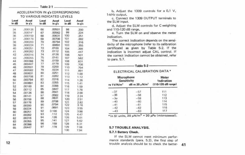
------- Table 2-1 -------
ACCELERATION IN g's CORRESPONDING
12
l ..... in cl8
34 35 36 37 38 39 40 41 42 43 44 45 46 47 48 49 50 51 52 53 54 55 56 57 58 59 60 61 62 63 64 65
TO VARIOUS INDICATED LEVELS Accel In Q'S
.000126
.00014'
.000159 .000118 .000200 .000224 .000251 .000282 .000316 .000355 000398 .000447 000501 000562 000631 000708 .000794 .000891 .00100 .00112 .00126 .00141 .00159 .00178 .00200 .00224 .00251 . 00282 .00316 .00355 .00398 .00447
l evel in dB
66 61 68 69 70 71 72 73 74 75 76 77 78 79 80 81 82 83 84 85 86 &7 88 89 90 91 92 93 94 95 96 97
Ace-' l..... Accel in g's in cl8 in~~
.00501 98 200
.00562 99 224
.00631 100 251
.00708 101 .282
.00794 102 .316
.00891 103 355 moo 104 .398 .0112 105 .447 .0126 106 .501 .0141 107 .562 . 0159 108 631 .0118 109 708 .0200 110 794 .0224 111 891 .0251 112 100 .0282 113 112 .0316 114 1 26 .0355 115 141 .0398 116 1 59 .0447 111 1 78 .0501 118 200 .0562 119 2.24 .0631 120 2.51 .o708 121 2.82 .0794 122 3 .16 .0891 123 3 .55
0.100 124 398 .112 125 4 47 .126 126 5.Ql . 141 127 562 159 128 631 118 129 708
130 7 94
b. Adjust the 1309 controls for a 0.1 V, 1-kHz output.
c. Connect the 1309 OUTPUT terminals to the SLM input.
d. Adjust the SLM controls for C weighting and 110-120 dB range.
e. Turn the SLM on and 'obserw the meter indication.
The correct indication depends on the sensi· tivity of the microphone (refer to its calibration certificate) as given by Table 5-2. If the indication is Incorrect adjust CAL control. If the correct Indication cannot be obtained, refer to para. 5.7 .
- -----T•ble 5-2------
ELECTRICAL CALIBRATION DATA •
Mic:rophone Sensitivity
re 1 V/N/m' dB re 20 llNim'
-37 - 57 -38 -58 -~ -59 -40 -60 - 41 -61 -42 -62 -43 -63
Meter lndir.ation
1110.120 dB range l
111 112 113 114 115 116 117
• 1n Sl units, 20 JJN/m2 • 20 JJPa (mlcropascall .
5.7 TROUBLE ANALYSIS. 5.7.1 B•ttery Check.
If the SLM cannot meet minimum perlor· mance standards (para. 5.2). the first step of trouble analysis should be to check the batter- 41
40
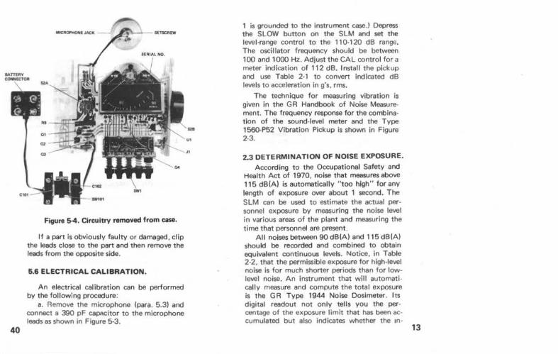
Figure 5-4. Circuitry removed from case.
If a part Is obviously faulty or damaged. clip the leads close to the part and then remove the leads from the opposite side.
6.6 ELECTRICAL CALIBRATION.
An electrical calibration can be performed by the following procedure:
a. Remove the microphone (para. 5.3) and connect a 390 pF cap;~citor to the microphone leads as shown in Figure 5-3.
1 is grounded to the instrument case.) Depress the SLOW button on the SLM and set the level-range control to the 1 10-120 dB range. The oscillator frequency should be between 100 and 1000 Hz. Adjust the CAL control for a meter indication of 112 dB. Install the pickup and use Table 2-1 to convert indicated dB levels to acceleration in g's, rms.
The technique for measuring vibration is given in the GR Handbook of Noise Measurement. The frequency response for the combine· tion of the sound-level meter and the Type 1560·P52 Vibration Pickup is shown in Figure 2-3.
2.3 DETERMINATION OF NOISE EXPOSURE. According to the Occupational Safety and
Health Act of 1970, noise t hat measures above 115 dB(A) is automatically "too high" for any length of exposure over about 1 second. The SLM can be used to estimate the actual personnel exposure by measuring the noise level in various areas of the plant and measuring the time that personnel are present.
All noises between 90 dB(A) and 115 dB(A} should be recorded and combined to obtain equivalent continuous levels. Notice, in Table 2-2. that the permissible exposure for high-level noise is for much shorter periods than for lowlevel noise. An instrument that will automati· cal ly measure and compute the total exposure is the GR Type 1944 Noise Dosimeter. Its digital readout not only tells you the percentage of the exposure limit that has been accumulated but also indicates whether the m-
13
14
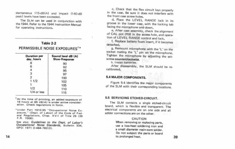
stantaneous 115-dB(A) and impact (140-dB peak) levels have been exceeded.
The SLM can be used in conjunction with the 1944. Refer to the 1944 Instruction Manual for operating instructions.
Table 2·2
PERMISSIBLE NOISE EXPOSURES'*
Duration per ~. hours
8 6 4 3 2 1 1/2 1 1/2 1/4 or less
Sound lwei dB (A) Slow-Responw
90 92 95 97
100 102 105 110 115
tAt the time of printing, an added expoJure of 16 hours at 86 dB(A) is under active consideration. Cheek regulations in force.
"Under Part 1910.95 .. Occupational Noise Ex· posure, .. (Dept. of Labor) of tha Code of Fed· eral Regulations. Chap. XVII of T itle 29 (39 F.R 7006).
See also: Guidelines to the Dept. of Lebor's Occupationel Noise Standards, Bulletin 334, GPO: 1971 0.484-782(3).
. c. Check that the flex circuit lays properly tn the case. Be sure it does not Interfere wi th the front case screw holes.
d. Place the LEVEL RANGE lock in its groove in the l01111er case, with the locking tab facing the microphone and down.
e. After case assembly, check the alignment of CAL POt (R9) in the access hole, and operation of LEVEL RANGE control and lock.
f. Replaoe battery foam insert, if it becomes detached.
g. Remount microphone with the 'L' on the socket mating the 'L' pin on the microphone. Tighten the microphone by adjusting the set· screw counterr:lockwise.
h. Install batteries. After disassembly, the SLM should be re
calibrated.
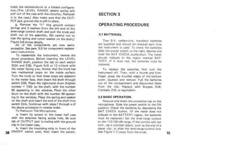
5.4 MAJOR COMPONENTS.
Figure 5-4 identifies the major components of the SLM with their corresponding locations.
5 .5 SERVICING ETCHED-CIRCUIT.
The SLM contains a single etched-circuit board. which is flexible and transparent. The electrical components are on one side and all solder connections are on the other.
CAUTION When removing or replacing parts, use a low-heat soldering iron and a small diameter rosin-core solder. Do not subject the parts or board to prolonged heat. 39
holds the etched-circuit in a folded configuration. (The LEVEL RANGE detent spring will pull out of the case with the circuitry. Reinstall it in the case. ) Also make sure that the OUTPUT jack ground clip Is still in place.
g. Remove the "c" ring ground contact springs and 2 washers from the left end of the level-range control shaft and pull the knob and shaft out of the assembly. (Be careful not to lose the spring and nylon washer on the shaft.l Figure S.S shows details.
All of the components are now easily accessible. See para. 5.5 for component replacement instructions.
To reassemble the instrument, reverse the above procedure. Before inserting the LEVEL RANGE shaft, position the tab on each switch (S2A and S2B, Figure 5-41 at 12 o'clock with the meter facing you. Notice that the knob has two mechanical stops on the inside surface. Tum the knob so that these stops are adjacent to the meter face. then insert the shaft through switch S2B. Place tHe right-hand drum (highest number = 130) on the shaft, with the number 90 appearing in the window. Place the other drum on the shaft with the number 80 appearing in the window. Place the spring and washer on the shaft and insert the end of the shaft into switch S2A. Continue with steps f through a of the above procedure In reverse order.
To Remount The Microphone; a. Insert its socket in the lower half case
with the setscrew facing access hole .• Be sure tab of OUTPUT jack is mating with the ground clip in the lower case.
b. Insert the insulating strip in front of the 38 ON/OFF switch post, then insert the switch.
SECTION 3
OPERATING PROCEDURE
3.1 BATTERIES.
Two 9-V. carbon-zinc. transistor batteries are supplied and should be checked each time the instrument is used. To check the batteries slide the power switch to the right, depress and hold the BAT CHECK pushbutton. The meter should indicate in the region marked BAT· TERY. If it does not, the batteries must be replaced.
To replace the batteries, first turn the instrument off. Then, with a thumb and fore· finger. grasp the knurled edges of the bottom cover. squeeze and remove. Pull the batteries out of the compartment and disconnect them from the clip. Replace with Burgess 2U6, Eveready 216, or equivalent.
3.2 BASIC OPERATION. Remove and retain the protective cap on the
microphone. Slide the power switch to the ON position. Check the batteries by depressing the BAT CHECK button. (If the meter does not indicate in the BATTERY region. the batteries must be replaced.) Set the level-range control to the 110-120 dB range. If the control will not turn. use a pointed object, such as the end of a paper clip, to slide the level-range-control lock (see Figure 1·1 I away from the knob. 15
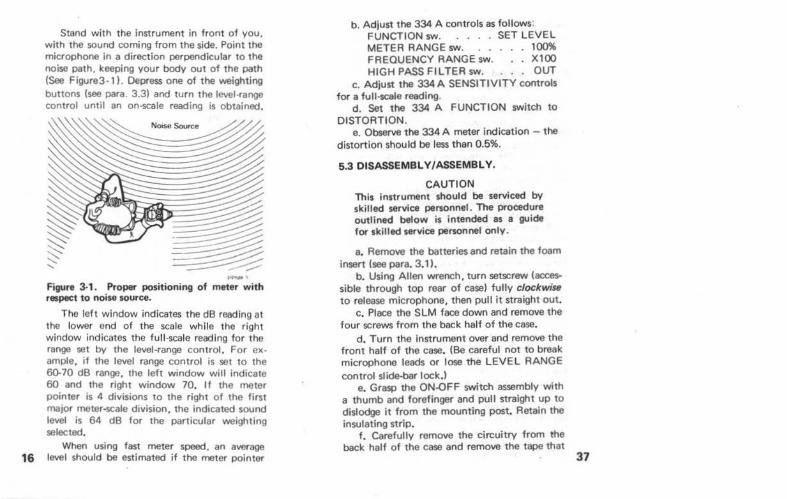
Stand with the instrument in front of you. with the sound coming from the side. Point the microphone in a direction perpendicular to the noise path. keeping your body out of the path (See Figure3·1l. Depress one of the weighting buttons (see para. 3.3) and turn the level-range control until an on-scale reading is obtained.
·-Figure 3-1. Proper positioning of meter with respect to noise source.
The left window indicates the dB reading at the lower end of the scale while the right window indicates the fu ll·scale reading for the range set by the level -range control . For example, if the level range control is set to the 60-70 dB range, the left window will indicate 60 and the right window 70. If the meter pointer is 4 divisions to the right of the first major meter-scale division, the indicated sound level is 64 dB for the particular weighting selected.
When using fast meter speed, an average 16 level should be estimated if the meter pointer
b. Adjust the 334 A controls as follows: FUNCTION sw. . . . . SET LEVEL METER RANGE sw. 100% FREQUENCY RANGE sw. . . X100 HIGH PASS Fl L TEA sw. . . OUT
c. Adjust the 334A SENSITIVITY controls for a full·scale reading.
d. Set the 334 A FUNCTION switch to DISTORTION.
e. Observe the 334 A meter indication - the distortion should be less than 0.5%.
5.3 DISASSEMBLY/ASSEMBLY.
CAUTION This instrument should be serviced by skilled service personnel. The procedure outlined below is intended as a guide for skilled service personnel only.
a. Remove the batteries and retain the foam insert (see para. 3.1 l.
b. Using Allen wrench, turn setscrew (accessible through top rear of easel fully clockwiss to release microphone, then pull it straight out.
c. Place the SLM face down and remove the four screws from the back half of the case.
d. Turn the Instrument over and remove the front half of the case. (Be careful not to break microphone leads or lose the LEVEL RANGE control slide-Oar lock.)
e. Grasp the ON.QFF switch assembly with a thumb and forefinger and pull straight up to dislodge it from the mounting post. Retain the insulating strip.
f. Carefully remove the circuitry from the back half of the case and remove the tape that
37
36
c. Connect the 2540 DVM to the oscllla· tor output and the Type 1192 Counter to the anenuator Input.
d. Connect a 600 n . 1% resistor across the OUTPUT terminals of the attenuator, then connect the anenuator OUTPUT to the Input of the SLM.
e. Connect the HP 334A (with a 600 n load across the input) to the SLM output jack .
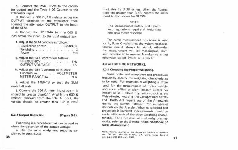
f. Adjust the SLM controls as follows: Level-range control 80..90 dB Weighting . . . . . . . . . . . C Power ............ ON
g. Adjust the 1309 controls as follows: FREQUENCY . . . . . . . . 1 kHz OUTPUT VOLTAGE . . . . . . 1 V
h. Adjust the 334A controls as follows: Function sw. . . . . VOLTMETER METER RANGE sw. . .... . 3 V
i. Adjust the 1450-TB so tnat the SLM reads full scale.
j . Observe the 334 A meter indication - it should be greater than 0.11 V (With the 600 n resistor removed from the 334 A Input, the voltage should be greater than 1.2 V rms.)
5.2.4 Ouq,ut Dist~tion (Figure 5-1).
Following is a prooedure that can be used to check the distortion of the output voltage:
a. Use the same equipment setup as explained in para. 5.2.3.
fluctuates by 3 dB or less. When the fluctua· tions are greater than 3 dB. depress the meter speed button (down for SLOW)
NOTE The Occupat•onal Safety and Health Act regulations require A weighting and slow meter response.
The same measurement procedure is used for A , B. or C weighting. the weighting characteristic should always be stated. otherwise. the measurement will be meaningless. Com· mon practice is to assume A weighting unless otherwise stated (ANSI S1.4-1971).
3.3 WEIGHTING NETWORKS.
3.3.1 Choosing the Proper Weighting.
Noise codes and acceptance-test procedures frequently specify the weighting characteristics to be used. For example, A -weighting is often used for the measurement of motor vehicle, appliance, office or plant noise. • Except for impact noise, Federal Regulations, such as the Walsh-Healey Act and the Occupational Safety and Health Act require use of the A network (hence the symbol "dB(A)" for sound-level decibels on the A scale). When no standard test procedure is involved, measurements should be made with each of the three weighting charac· teristics. For a full discussion of weighting net· works, refer to the General Radio Handbook of Noise M88surement.
• R w. Vouno Jo"'r~l ot the Acouu lc• l Society ot Ametlce, Vol. 38. PO 218 2$S t1 H... O.P Love, No••• Cormot, Vol. 5, pp, 230 235, July, I 850 17
18
• • • ~ ~
,.... . .~~ c / v I
.. / I / . v .~~=:;'~;cs / • 1/ t-
, /
•
, / to •• •oo - ""'·- ,_ .... .. -
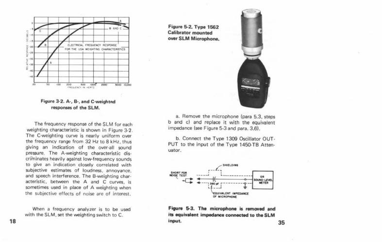
Figure 3·2. A·. B-, and C·weightlld resporl$8$ of the SLM.
The frequency response of the SLM for each weighting characteristic is shown in Figure 3·2. The C·weighting curve is nearly uniform over the frequency range from 32 Hz to 8kHz. thus giving an indication of the over-all sound pressure. The A-weighting characteristic dis· criminates heavily against low-frequency sounds to give an indication closely correlated with subjective estimates of loudness. annoyance. and speech interference. The B·weighting char· acterlstic. between the A and C curves. is sometimes used in place of A weighting when the subjective effects of noise are of interest.
When a frequency analyzer is to be used with the SLM. set the weighting switch to C.
Figure 5-2. Type 1662 Calibrator mounted owr SLM Microphone •
a. Remove the microphone (para 5.3, steps b and c) and replace it with the equivalent impedance (see Figure 5·3 and para. 3.61.
b. Connect the Type 1309 Oscillator OUT· PUT to the Input of the Type 1450-TB Atten· uator .
LSMitLOUf$
~~~~ :-.~~~;~~~--~_-:_·_·f-1~~ "OUiw.LOT I MI"£JWWC:( 01 MIC~
Figure 5-3. The mic:l'ophone is remO¥ed and iu -.uiv.,eflt impedance connected to the SLM input. 35
;i ~ ~
z
~ -- f
~ ~
~~
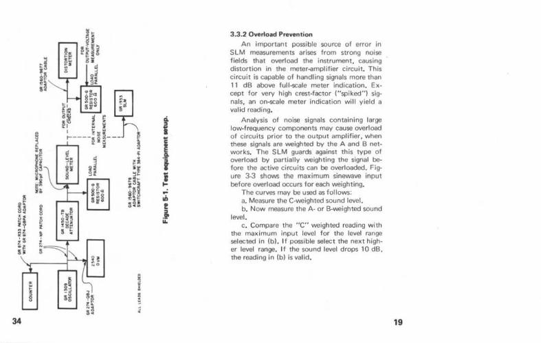
~~ 53i .... ~ !~!! -c-o:O JII .. c ..
34
ci.
i .l t i ... .; Iii ! .t "'
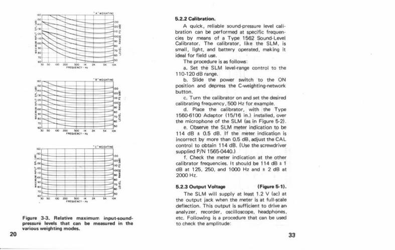
3 .3.2 Overload Prevention An important possible source of error in
SLM measurements arises from strong noise fields that overload the instrument, causing distortion in the meter-amplifier circuit. This circuit is capable of handling signals more than 11 dB above full-scale meter indication. Except for very high crest-factor ("spiked") slg· nals, an on-scale meter indication will yield a valid reading.
Analysis of noise signals containing large low-frequency components may cause overload of circuits prior to the output amplifier, when these signals are weighted by the A and B networks. The SLM guards against this type of overload by partially weighting the signal before the active circuits can be overloaded. Figure 3-3 shows the maximum sinewave input before overload occurs for each weighting •
The curves may be used as follows: a. Measure the C-weighted sound level. b. Now measure the A- or B-weighted sound
level. c. Compare the "C" weighted reading with
the maximum input level for the level range selected in (b). If possible select the next high· er level range. If the sound level drops 10 dB. the reading in (b) is valid.
19
20
.. 00
F::::
:::-
.
- -
-
I
"" Ito
biiO ~· - = to
1--: --= •• 1--::: ..
» .o 100 100 aoo 11e zc ,. ~ U(OUC~Y "'
Figure 3-3. Relative maximum input-sound· pressure levels that can be measured in the various weighting modes.
5.2.2 C .. lbretion. A quick, reliable sound-pressure level cali
bration can be perlormed at specific frequencies by means of a Type 1562 Sound·Level Calibrator. The calibrator, like the SLM, is small, light, and battery operated, making it ideal for field use.
The procedure is as follows : a. Set the SLM level-fange control to the
110·120 dB range. b. Slide the power switch to the ON
position and depress the C·weighting-network button.
c. Turn the calibrator on and set the desired calibrating frequency , 500 Hz for example.
d. Place the cal ibrator, with the Type 1560-6100 Adaptor (15/16 ln.) Installed, over the microphone of the SLM (as In Figure 5·2) .
e. Observe the SLM meter indication to be 114 dB :1: 0.5 dB. If the meter Indication is incorrect by more than 0.5 dB, adjust the CAL control to obtain 114 dB. (Use the screwdriver supplied P/N 1565-0440.)
f. Check the meter Indication at the other calibrator frequencies. It should be 114 dB :1: 1 dB at 125, 250, and 1000 Hz and :1: 2 dB at 2000 H~.
5.2.3 Output VoiUge (Fiture 5-1). The SLM will supply at least 1.2 V (ac) at
the output jack when the meter is at full-scale deflection. This output is sufficient to drive an analyzer. recorder. oscilloscope, heed phones, etc. Following is a procedure that can be used to check the amplitude:
33
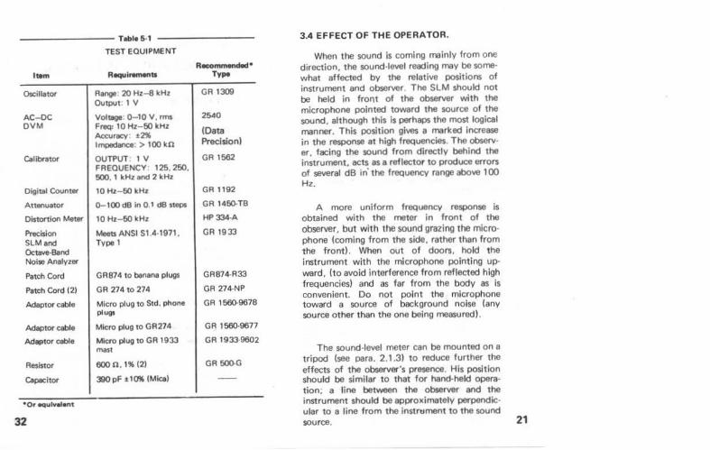
Tobie 6·1
TEST EQUIPMENT
I *'I R.i..-1:1
OscillatOf Range 20 Hz-8 kHz OutPUt IV
A C-DC Voltage 0-10 V, rms DVM Freq: 10Hz-50 kHz
A«;urt/C'( t2% Impedance.> 100 kO
Callbnltof OUTPUT IV FREQUENCY 125, 250. 500. I kHz and 2 kHz
Digital Countar 10Hz- 50kHz
Attenuator Q-100 dB In 0.1 dB steps
Distortion Meter 10Hz- 50 kHz
Precision MMtsANSI 51 4·1971, SLMand Type 1 Octave·Band Noise Analyzer
Patch Cord GR874 to benana plugs
Patch Cord (2) GR 274 to 274
Adapt Of ceble Micro plug to Std. phone plugs
Adaptor ceble Micro plug to GR274
Adaptor ceble Micro plug to GR 1933 mast
Resistor 600 n. 1% 121
CepacitOf 390 pF t10'K (Mica)
•or equtvel.nt
32
Recommended• TyJM
GR 1309
2540
(Data Precision)
GR 1562
GR 1192
GR 146(). TB
HP334-A
GR 1933
GR874·R33
GR 274-NP
GR 1560-9678
GR 1560-9677
GR 1933··9602
GR 50Q.G
3.4 EFFECT OF THE OPERATOR.
When the sound is coming mainly from one direction, the sound·level reading may be some· what aHected by the relative positions of instrument and observer. The SLM should not be held in front of the observer with the microphone pointed toward the source of the sound. although this is perhaps the most logical manner. This position gives a marked increase in the response at high frequencies. The observ· er. facing the sound from directly behind the instrument, acts as a reflector to produce errors of several dB in' the frequency range above 100 Hz.
A more uniform frequency response is obtained with the meter in front of the observer. but with the sound grazing the micro· phone (coming from the side, rather than from the front). When out of doors, hold the instrument with the microphone pointing up· ward, ho avoid interference from reflected high frequencies) and as far from the body as is convenient. Do not point the microphone toward a source of background noise (any source other than the one being measured).
The sound·level meter can be mounted on a tripod (see para. 2.1 .3) to reduce further the eHects of the observer's presence. His position should be similar to that for hand·held opera· tion; a line between the observer and the instrument should be approximately perpendic· ular to a line from the instrument to the sound source. 21
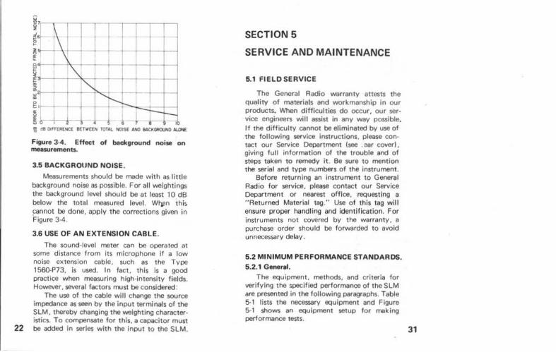
Figure 3-4. Effect of background noise on mea$Urements.
3.5 BACKGROUND NOISE.
Measurements should be made with as little background noise as possible. For all weightings the background level should be at least 10 dB below the total measured level. Wt)#!n thi~ ~nnot be done. apply the corrections given in Figure 3-4.
3.6 USE OF AN EXTENSION CABLE.
The sound-level meter can bo operated at some distance from its microphone if a low noise extension cable, such as the Type 1560-P73. is used. In fact. this is a good practice when measuring high intensity fields. However. several factors must be considered:
The use of the cable will change the source impedance as seen by the input terminals of the SLM. thereby changing the weighting character· istics. To compensate for this. a capacitor must
22 be added in series with the input to the SLM.
SECTION 5
SERVICE AND MAINTENANCE
5.1 FIELD SERVICE
The General Radio warranty attests the quality of materials and workmanship in our products. When difficulties do occur, our service engineers will assist in any way possible. If the difficulty cannot be eliminated by use of the following service instructions. please con· tact our Service Oepanment (see . ear cover), giving full information of the trouble and of steps taken to remedy it. Be sure to mention the serial and type numbers of the instrument.
Before returning an instrument to General Radio for service, please contact our Service Department or nearest office. requesting a " Returned Material tag." Use of this tag will ensure proper handling and identif ication. For instruments not covered by the warranty, a purchase order should be forwarded to avoid unnecessary delay.
5.2 MINIMUM PERFORMANCE STANDARDS.
5.2.1 G-rel. The equipment, methods, and criteria for
verifying the specified performance of the SLM are presented in the following paragraphs. Table 5-1 lists the necessary equipment and Figure 5-1 shows an equipment setup for making performance tests.
31
30
... ~~-----------. ,.,. ~ " ......... to ....... ,.,.,. Olft,m 1ft ....w _, wert...
........ .....-.v~·~ ... ~...,.,.... ......... ,.. Gllll~~..-. • .,_, ~--~"""'~ .... aWioc' fli Oflt.,_.twor~ ........ wlllt.,..,.... OI' ,..,._.M ,.dWI'.,_'""""'.,. o.- _..edltv.
0" ~ k 110 Mlln'liliM...,. CIJPIIblllitv fOf • '*106 of ""vw• .,,. 1N .......... lhl..,.,..m. .,..., • Mike .w Cill)lllllfty ............ ..,. "'*' .,.......,.. .,....,.. _.~lor'"",~~ • •GR ..,..tdifY, a-.- tft lht~MC..,...,... io¥ 0flltNI.oldthii.,..,.,..'Y Gftiii'IMWIIIfot _,_ Thill~ I."' Kw., tM ..._ W~~WNndll. tx---' or...,...., ..........
...... ..... .. ................... ~-fi ........ --
1400 I+ H- ,. f-~ .....
~-
1-l H 1-
0 tj
f-t I ~ f1
0 00
LOSS~ .
~tTAHC(
1
FE ~·
!+ IZ
IT ,_
-
10
• • . § i u
z
:aS
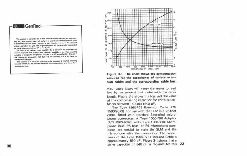
Figure 3-5. The chart shows the compensation required for the cai)Kitance of various exten· sion cables and the corresponding cable loss.
Also, cable losses will cause the meter to read low by an amount that varies with the cable length. Figure 3-5 shows the loss and the value of t he compensating capacitor for cable capaci· tances between 150 and 1500 pF.
The Type 1560·P73 Extension Cable (P/N 1560-9673). for use with the SLM is a 25-foot cable, fitted with standard 3-terminal micro· phone connectors. A Type 1560-P96 Adaptor (P/N 1560-9696) and a Type 1560·3040 Microphone Base, P5 base, or P5 microphone complete, are needed to mate the SLM and the microphone with the connectors. The capacitance of the Type 1560-P73 Extension Cable is approximately 550 pF. Figure 3-5shows that a series capacitor of 640 pF is required for this 23
24
cable capacitance. This capacitor can be in· stalled in the Type 1560·P96 Adaptor. as follows:
a. Remove the outer shell of the adaptor by turning t he setscrew In the side of the shell in a clockwise direction and pulling the shell off the adaptor.
b. Remove the lead connecting terminal No. 3 of the microphone connector to one of the teflon insulated pin plugs, and replace the lead with a small mica or ceramic capacitor of about 640 pF.
c. Replace the outer shell.
The value of capacitance to be used with other cables can be determined from Figure 3-5
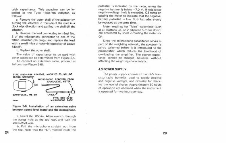
To connect an extension cable. proceed as follows (see Figure 3-6) ·
ADAPTOR, MODI FIED TO INCLUDE
loUCROPHONE REIIIOVEO FROM SOUNO'LEVEL METER
SOUNO-LEVEL loiETER C0 CABLE TYPE 156CHI040
loiiCROPWONE BASE
Figure ~. Installation of an extension cable between sound·level meter and the microphone.
a. Insert tho .050-in. Al len wrench, through the aocess hole at the top rear. and turn the screw clockwise.
b. Pull the microphone straight out from the top. Note that the "L", molded inside the
potential is indicated by the meter. unless the negative battery is below -7.0 V. If this lower negative·voltage limit is exceeded, 03 turns on causing the meter to indicate that the negativebattery potential is low. Both batteries should be replaced at the same time. ·
Meter read ings for "false" weightings (such as all bunons up, or 2 adjacent buttons down) are prevented by short circuiting the meter via 04.
Sinoe the microphone capacitance serves as part of the weighting network. the sP"(:trum is partly weighted before it is introduced to the preamplifier, which reduces the likelihood of overloading the amplifier. The source capaci· tance cannot be changed, however, without affecting the weighting characteristic.
4.3 POWER SUPPLY.
Tha power supply consists of two g.v tran· sistor·radio battenes. used to supply positive and negative voltages, and circuitry for check· ing the level of charge. Approximately 50 hours of operation are obtained when the instrument is operated for two hours per day.
29
28
4.2 MAIN CIRCUITRY. Transistors 01 and 02 comprise the active
elements of the preamplifier. 01 is a low noise. N-channel. field-effect transistor and operates in conJunction with a high-gain. bipolar transis· tor (02) to stabilize the gain. R9. a potentiom· eter in the preamplifier feedback loop. is used to calibrate the Instrument.
The main amplifier consists of one integrated circuit that provides low output imped· ance and high gain - gain is stabilized via the feedback loop. This amplifier drives both the meter detector circuit and the output terminals.
The attenuator is divided into two sections for best signal·to·noise ratio. One section pre· cedes the input amplifier; the other is between the amplifier stages. The attenuation is adjust able in 1()-dB steps.
Each coupling and feedback path in the SLM serves double duty by forming part of the weighting network. The main amplifier feed· back loop shapes the 733-Hz and B·kHz rolloff for A-weighting and A·. B·. and C-weighting. respectively. Rolloff at 107Hz for A-weighting, 160 Hz for B·weighting and 32 Hz for C-welght· ing is accomplished by the combination of transducer capacitance and input load resis· tance. The 32-Hz rolloff for A· and B·weighting is formed by the preamplifier output coupling circuit and the second section of the attenua· tor.
The battery-check circuit utilizes the meter and a sensing circuit consisting of 03. CR4, CR5. and associated resistors. When the BAT CHECK button is depressed the positive-battery
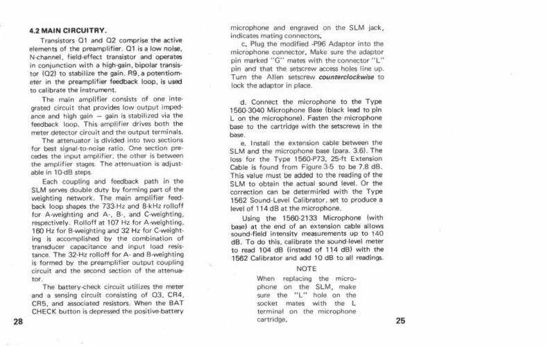
microphone and engraved on the SLM jack, indicates mating connectors.
c. Plug the modified ·P96 Adaptor into the microphone connector. Make sure the adaptor pin marked "G" mates with the connector " L" pin and that the setscrew access holes line up. Turn the Allen setscrew counterclockwise to lock the adaptor in place.
d. Connect the microphone to the Type 1560·3040 Microphone Base (black lead to pin L on the microphone) . Fasten the microphone base to the cartridge with the setscrews in the base.
e. 1 nstall the extension cable between the SLM and the microphone base (para. 3.61. The loss for the Type 1560·P73. 25-ft Extension Cable is found from Figure 3-5 to be 7.8 dB. This value must be added to the reading of the SLM to obtain the actual sound level. Or the correction can be determined with the Type 1562 Sound·Level Calibrator. set to produce a level of 114 dB at the microphone.
Using the 1560·2133 Microphone (with base) at the end of an extension cable allows sound·field intensity measurements up to 140 dB. To do this. calibrate the sound·level meter to read 104 dB (instead of 114 dB) with the 1562 Calibrator and add 10 dB to all readings.
NOTE When replacing the microphone on the SLM. make sure the "L" hole on the socket mates with the L terminal on the microphone cartridge. 25
26
3.7 PREFERRED ANGLE DF INCIDENCE. When measurements are made on sounds In
reverberant fields, the angle of incidence of sounds reaching the microphone is indeterml· nant. In this case. there is no prefem!cl argle of incidence between the microphone and the sound source. When measurements are made on a source In a free field. an angle of incidence of 70 degrees between the axis of the microphone and the sound source will approximate random response.
3.8 USE AS A PREAMPLIFIER.
The SLM can be used as a preamplifier for the G R 1558 Octave·Band Noise Analyzer to make low level octave-band measurements (I.e. below the low end of the 1558 sound-level range). Following is a recommended procedure:
a. Connect the SLM output to the 1558 INPUT (SLM) jack with the GR 1560·P78 (P/N 1560-9678) adaptor cable.
b. Adjust the SLM controls as follows Level-range control . 110/120 Meter speed . . . . • . . . SLOW Weighting . . . . . . . . . . . C Power sw. . . . . . . . . . ON
c. Adjust the 1558 controls as follows Function sw. Fast Band CPS . . . . . . . . ALL PASS BAND LEVEL dial . . 12:00o'clock BAND LEVEL knob . . . . .Fully cw
d. Use the GR 1582 Calibrator to make the SLM read 114 dB: adjust the 1558 CAL con· trol for a +4 meter Indication. The setup is now calibrated so that a 1558 meter Indication of 0
. "'
equals the low end of the SLM range setting. e. Set the SLM level·range control for an
on scale indication or the lowest range. f . Set the BAND CPS control to the desired
band. g. Set the BAND LEVEL knob for an on
scale reading. The band level in dB is the algebraic sum of the 1558 meter indication + the BAND LEVEL knob setting (red scale only)+ the low end of the SLM range setting.
SECTION 4
PRINCIPLES OF OPERATION
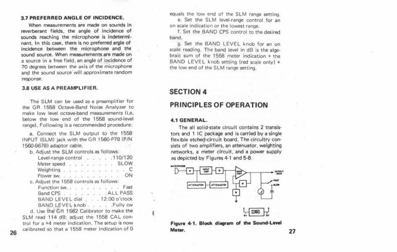
4.1 GENERAL. The all solid·state circuit contains 2 transis·
tors and 1 IC package and is carried by a single flexible etched-circuit board. The circuitry con· sists of two amplifiers. an attenuator. weighting networks. a meter circuit. and a pow8f supply as depicted by Figures 4·1 and 5-8.
I r;:;;;;-U ~
Figure 4-1 . Block di•em of the Sound-Left!
Meter. 27
J-- t .ti.AciT -t-,.,.c.sr PrTCU ~ I.UI"'tiir Rrllf!At.l,-1~~ f-~NO RrTCiVVPTO~ 1 Alfllll~ RNf/'I(,.I,IC.t:. -f-MCrCe C¥73 ovrPt.ir
.SW/6 (8 W .... )
Q: o&Mt41-
"
4 ' •• ' ~· , L ___ /t. S WtC.
~Wi IDCNni'ICIITION
.S«noN R 6 C D C
n m nr . m_l!Lll
C4 I.J,a
~·.-
I
I
.., ... .. , so
-·· ~a A
-fuvtt~t
C.JU
.. « INCI<Hn"" J Cl'
,c_,
!;WI C. (~wTG)
SC.HEMAT I C. 5HOWN ON 40d8, (W16, FAC::.T
_,_
"" ~.f. (,/1( ~
•• r!i] -o .;. .. ,. ~~-~
'1.11K /!OS ,. _, lti.S' ~,.
4.~/iK .... .. 0
"'" 7,~
~
... -<;;
...
lt .. 4
..c,~ l./] ovrAtr :::>. •t-..... ,..--, -r• -..... .. J J ..
c ....
' c .. .. s•-
-!o..._'Q-~ • {M • 4 ~ O·roo,...._
'\Wit
f'i.i'Tm] l Clll tCot I (MOMENTo~Y
nr~
~~~,~ ~~K? ~-A
u~ ~ ellS'
II '( Cll4
·9"
l!fi"JTT~~y ~ 3 111/frt:N 11$34"_.,/kY
0
··~ . ~1 ·~l- .... ~· ::~,
h,·., ,_cKJ: f O J IJIIOI.
..... _ '"' ,.,_, .$N101
/1.R.JC D/1111/1./CAt+U
Ql Q.t
6AT~ Cou
~S) 80 DlrRJN ~"""
( 8077'0/ltl't Y'CW)
I ""'{ <et
\..:..) ~ ~ G~t• ·l<l
,..,. -, J ,- II• co~S])
1.,_,Ji.,.lf :.. •• OIITI"Uf ..,...,.,_,..,y -' I.. ~tW1'J •.
u' (7»1" ·-)
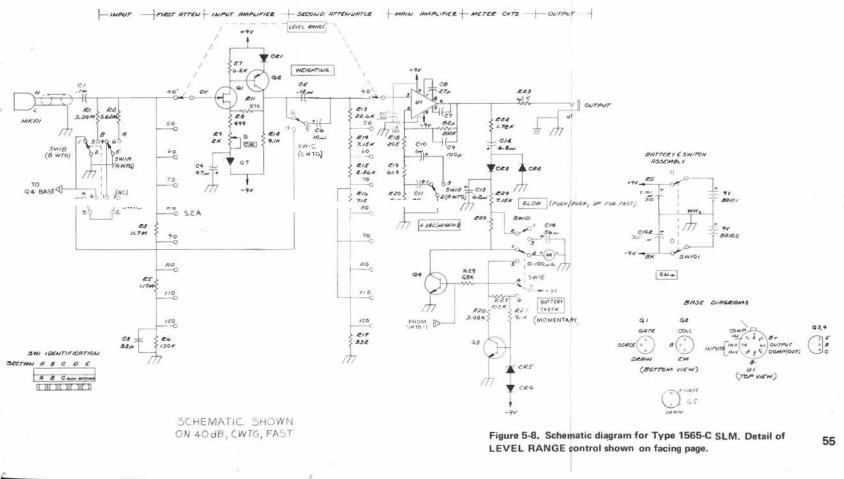
Figure 5-8. Schematic diagram for Type 1565-C S LM. Detail of LEVEL RANGE control shown on facing page.
QJ.•
Gl'
# 0
55