Embed Size (px)
Citation preview
8/13/2019 1657_prextherm t 3g It+Gb
http://slidepdf.com/reader/full/1657prextherm-t-3g-itgb 1/36
PREXTHERM T 3G

8/13/2019 1657_prextherm t 3g It+Gb
http://slidepdf.com/reader/full/1657prextherm-t-3g-itgb 2/36

8/13/2019 1657_prextherm t 3g It+Gb
http://slidepdf.com/reader/full/1657prextherm-t-3g-itgb 3/36
PREXTHERM T 3G
Manuale Tecnico - Installazione - Uso e Manutenzione
PREXTHERM T 3G
Technical Manual - Installation - User and Maintenance
IT
GB
pag. 4
page 16
Cod. 35451950 - 02.06

8/13/2019 1657_prextherm t 3g It+Gb
http://slidepdf.com/reader/full/1657prextherm-t-3g-itgb 4/36- 4 -
INDICE
1. Presentazione . . . . . . . . . . . . . . . . . . . . . . . . . . . . . . . . . . . . . . . . . . . . . . . . . . . . . . . . . . . . . . . . . . . . . . . . . . . . . . . . . pag. 52. Avvertenze generali . . . . . . . . . . . . . . . . . . . . . . . . . . . . . . . . . . . . . . . . . . . . . . . . . . . . . . . . . . . . . . . . . . . . . . . . . . . . pag. 53. Certificazione . . . . . . . . . . . . . . . . . . . . . . . . . . . . . . . . . . . . . . . . . . . . . . . . . . . . . . . . . . . . . . . . . . . . . . . . . . . . . . . . . pag. 54. Caratteristiche tecniche, costruttive e dimensionali . . . . . . . . . . . . . . . . . . . . . . . . . . . . . . . . . . . . . . . . . . . . . . . . . . . . pag. 5
4.1 Descrizione dell’apparecchio . . . . . . . . . . . . . . . . . . . . . . . . . . . . . . . . . . . . . . . . . . . . . . . . . . . . . . . . . . . . . . . . . . . pag. 54.2 Principio di funzionamento . . . . . . . . . . . . . . . . . . . . . . . . . . . . . . . . . . . . . . . . . . . . . . . . . . . . . . . . . . . . . . . . . . . . pag. 64.3 Dati tecnici - Dimensioni - Attacchi idraulici . . . . . . . . . . . . . . . . . . . . . . . . . . . . . . . . . . . . . . . . . . . . . . . . . . . . . . . . pag. 64.4 Identificazione . . . . . . . . . . . . . . . . . . . . . . . . . . . . . . . . . . . . . . . . . . . . . . . . . . . . . . . . . . . . . . . . . . . . . . . . . . . . . . pag. 7
5. Installazione . . . . . . . . . . . . . . . . . . . . . . . . . . . . . . . . . . . . . . . . . . . . . . . . . . . . . . . . . . . . . . . . . . . . . . . . . . . . . . . . . . . pag. 75.1 Imballo . . . . . . . . . . . . . . . . . . . . . . . . . . . . . . . . . . . . . . . . . . . . . . . . . . . . . . . . . . . . . . . . . . . . . . . . . . . . . . . . . . . . pag. 75.2 Movimentazione . . . . . . . . . . . . . . . . . . . . . . . . . . . . . . . . . . . . . . . . . . . . . . . . . . . . . . . . . . . . . . . . . . . . . . . . . . . . pag. 75.3 Locale di installazione della caldaia . . . . . . . . . . . . . . . . . . . . . . . . . . . . . . . . . . . . . . . . . . . . . . . . . . . . . . . . . . . . . pag. 75.4 Scarico dei prodotti della combustione . . . . . . . . . . . . . . . . . . . . . . . . . . . . . . . . . . . . . . . . . . . . . . . . . . . . . . . . . . . pag. 75.5 Collegamenti idraulici . . . . . . . . . . . . . . . . . . . . . . . . . . . . . . . . . . . . . . . . . . . . . . . . . . . . . . . . . . . . . . . . . . . . . . . . pag. 7
5.5.1 Acqua di alimentazione . . . . . . . . . . . . . . . . . . . . . . . . . . . . . . . . . . . . . . . . . . . . . . . . . . . . . . . . . . . . . . . . . . pag. 75.5.2 Tubazioni mandata/ritorno impianto . . . . . . . . . . . . . . . . . . . . . . . . . . . . . . . . . . . . . . . . . . . . . . . . . . . . . . . . pag. 8
5.5.3 Tubazioni riempimento/scarico impianto . . . . . . . . . . . . . . . . . . . . . . . . . . . . . . . . . . . . . . . . . . . . . . . . . . . . . pag. 85.5.4 Tubazioni vaso espansione e valvola di sicurezza . . . . . . . . . . . . . . . . . . . . . . . . . . . . . . . . . . . . . . . . . . . . . pag. 85.5.5 Pompa ricircolo . . . . . . . . . . . . . . . . . . . . . . . . . . . . . . . . . . . . . . . . . . . . . . . . . . . . . . . . . . . . . . . . . . . . . . . . pag. 8
6. Componenti della caldaia . . . . . . . . . . . . . . . . . . . . . . . . . . . . . . . . . . . . . . . . . . . . . . . . . . . . . . . . . . . . . . . . . . . . . . . . . pag. 86.1 Porta anteriore . . . . . . . . . . . . . . . . . . . . . . . . . . . . . . . . . . . . . . . . . . . . . . . . . . . . . . . . . . . . . . . . . . . . . . . . . . . . . . pag. 86.2 Porte anteriori apertura e regolazioni . . . . . . . . . . . . . . . . . . . . . . . . . . . . . . . . . . . . . . . . . . . . . . . . . . . . . . . . . . . . pag. 96.3 Porte posteriori apertura e regolazioni . . . . . . . . . . . . . . . . . . . . . . . . . . . . . . . . . . . . . . . . . . . . . . . . . . . . . . . . . . . pag. 96.4 Tampone di accesso al focolare . . . . . . . . . . . . . . . . . . . . . . . . . . . . . . . . . . . . . . . . . . . . . . . . . . . . . . . . . . . . . . . . pag. 96.5 Montaggio del bruciatore . . . . . . . . . . . . . . . . . . . . . . . . . . . . . . . . . . . . . . . . . . . . . . . . . . . . . . . . . . . . . . . . . . . . . . pag. 96.6 Collegamento spia controllo fiamma . . . . . . . . . . . . . . . . . . . . . . . . . . . . . . . . . . . . . . . . . . . . . . . . . . . . . . . . . . . . . pag. 9
7. Pannello strumenti standard . . . . . . . . . . . . . . . . . . . . . . . . . . . . . . . . . . . . . . . . . . . . . . . . . . . . . . . . . . . . . . . . . . . . . . . pag. 107.1 Pannello . . . . . . . . . . . . . . . . . . . . . . . . . . . . . . . . . . . . . . . . . . . . . . . . . . . . . . . . . . . . . . . . . . . . . . . . . . . . . . . . . . pag. 10
7.2 Vista frontale pannello . . . . . . . . . . . . . . . . . . . . . . . . . . . . . . . . . . . . . . . . . . . . . . . . . . . . . . . . . . . . . . . . . . . . . . . . pag. 107.3 Schema delle connessioni elettriche morsettiera . . . . . . . . . . . . . . . . . . . . . . . . . . . . . . . . . . . . . . . . . . . . . . . . . . . pag. 107.4 Schema elettrico per bruciatore e pompa monofase . . . . . . . . . . . . . . . . . . . . . . . . . . . . . . . . . . . . . . . . . . . . . . . . . . . . pag. 11
8. Schema di principio . . . . . . . . . . . . . . . . . . . . . . . . . . . . . . . . . . . . . . . . . . . . . . . . . . . . . . . . . . . . . . . . . . . . . . . . . . . . . . pag. 129. Avviamento . . . . . . . . . . . . . . . . . . . . . . . . . . . . . . . . . . . . . . . . . . . . . . . . . . . . . . . . . . . . . . . . . . . . . . . . . . . . . . . . . . . . pag. 13
9.1 Controlli preliminari . . . . . . . . . . . . . . . . . . . . . . . . . . . . . . . . . . . . . . . . . . . . . . . . . . . . . . . . . . . . . . . . . . . . . . . . . . pag. 139.2 Prima accensione . . . . . . . . . . . . . . . . . . . . . . . . . . . . . . . . . . . . . . . . . . . . . . . . . . . . . . . . . . . . . . . . . . . . . . . . . . . pag. 13
9.3 Spegnimento caldaia . . . . . . . . . . . . . . . . . . . . . . . . . . . . . . . . . . . . . . . . . . . . . . . . . . . . . . . . . . . . . . . . . . . . . . . . . . . . . pag. 1310. Manutenzione . . . . . . . . . . . . . . . . . . . . . . . . . . . . . . . . . . . . . . . . . . . . . . . . . . . . . . . . . . . . . . . . . . . . . . . . . . . . . . . . . . pag. 13
10.1 Norme generali . . . . . . . . . . . . . . . . . . . . . . . . . . . . . . . . . . . . . . . . . . . . . . . . . . . . . . . . . . . . . . . . . . . . . . . . . . . . . pag. 1310.2 Manutenzione ordinaria . . . . . . . . . . . . . . . . . . . . . . . . . . . . . . . . . . . . . . . . . . . . . . . . . . . . . . . . . . . . . . . . . . . . . . . pag. 1310.3 Manutenzione straordinaria . . . . . . . . . . . . . . . . . . . . . . . . . . . . . . . . . . . . . . . . . . . . . . . . . . . . . . . . . . . . . . . . . . . . pag. 1310.4 Lavaggio alcalino o bollitura . . . . . . . . . . . . . . . . . . . . . . . . . . . . . . . . . . . . . . . . . . . . . . . . . . . . . . . . . . . . . . . . . . . pag. 14
10.5 Conservazione del generatore . . . . . . . . . . . . . . . . . . . . . . . . . . . . . . . . . . . . . . . . . . . . . . . . . . . . . . . . . . . . . . . . . pag. 1410.6 Verifica di funzionamento della caldaia . . . . . . . . . . . . . . . . . . . . . . . . . . . . . . . . . . . . . . . . . . . . . . . . . . . . . . . . . . . pag. 1410.7 Verifica di funzionamento del bruciatore . . . . . . . . . . . . . . . . . . . . . . . . . . . . . . . . . . . . . . . . . . . . . . . . . . . . . . . . . . pag. 1410.8 Possibili guasti e rimedi . . . . . . . . . . . . . . . . . . . . . . . . . . . . . . . . . . . . . . . . . . . . . . . . . . . . . . . . . . . . . . . . . . . . . . . pag. 14
11. Elenco ricambi . . . . . . . . . . . . . . . . . . . . . . . . . . . . . . . . . . . . . . . . . . . . . . . . . . . . . . . . . . . . . . . . . . . . . . . . . . . . . . . . . . pag. 15
8/13/2019 1657_prextherm t 3g It+Gb
http://slidepdf.com/reader/full/1657prextherm-t-3g-itgb 5/36- 5 -
IT
1. PRESENTAZIONE
Gentile Cliente,La ringraziamo di aver scelto una caldaia PREXTHERM T 3G.Questo manuale è stato preparato per informaLa, con avver-tenze e consigli, sulla installazione, il corretto uso e la manu-
tenzione della caldaia e di conservarlo con cura per ogni ulte-riore consultazione.
Nel suo interesse, la invitiamo a seguire ed osservare conattenzione in modo da poter al meglio e con piena soddisfa-zione usufruire di questo prodotto di alta qualità.L’inadempienza delle stesse e l’inosservanza di quanto ripor-
tato in questo manuale esonerano la Ditta Costruttrice daqualsiasi responsabilità ed invaliderà la garanzia stessa.
2. AVVERTENZE GENERALI
- Il manuale istruzioni è parte integrante del prodotto e forni-sce una descrizione di tutto ciò che deve essere osservatoin fase di installazione, uso e manutenzione.
- Questo apparecchio deve essere destinato solo all’uso per ilquale è stato espressamente previsto.
- Questo apparecchio serve a riscaldare acqua ad una
temperatura inferiore a quella di ebollizione a pressio-
ne atmosferica e deve essere allacciato ad un impianto
di riscaldamento e/o ad un impianto di distribuzione
acqua calda per uso sanitario, compatibilmente alle sue
caratteristiche e prestazioni ed alla potenza termica.
- È opportuno verificare, prima dell’installazione, che la cal-daia non abbia subito danni derivanti la movimentazione edi trasporto.
- L’installazione deve essere effettuata in ottemperanza allenorme vigenti, da personale opportunamente qualificato.
- Prima di effettuare qualsiasi operazione di pulizia o di manu-tenzione, disinserire l’apparecchio dalla rete di alimentazione.
- La Ferroli S.p.A. non risponde per danni a persone e/a cosedovuti ad errori di installazione, regolazione, di manutenzio-ne e da usi impropri.
- L’avviamento della caldaia e del relativo impianto, devonoessere eseguiti da persona autorizzata.
- Il primo avviamento a lo scopo di verificare il buon funziona-mento di tutti i dispositivi di regolazione e controllo.
- Il non utilizzo dell’apparecchio per un lungo periodo necessi-ta dell’intervento di personale qualificato.
- L’installatore deve rispettare le regolamentazioni locali inmateria di: il locale scelto sia idoneo all’installazione dellacaldaia, siano rispettate le necessarie condizioni di aerazio-ne, il collegamento e il camino siano a perfetta tenuta, i col-legamenti del combustibile, impianti elettrici ed eventualialtre disposizioni locali e di sicurezza.
- Fare attenzione ad eventuali pareti superficiali calde anterio-ri e posteriori.
- È OBBLIGATORIO installare un pressostato differenzialeacqua che intervenga per mancanza d’acqua.
Condizioni di garanzia
La validità della garanzia è subordinata all’osservanza dellenorme e dei consigli di utilizzo contenute in questo manuale,ogni inosservanza o modifica la renderà nulla. Non sonoassolutamente riconosciuti dalla garanzia danni dovuti allacorrosione da condensa acida dei prodotti della combustioneo conseguenti alla formazione di incrostazioni causatedall’uso di acque dure o aggressive, in quanto imputabili allasola conduzione dell’impianto.
Normative
L’installatore deve rispettare le regolamentazioni locali evigenti per quanto riguarda: la scelta del luogo di installazionedella caldaia, il rispetto delle necessarie condizioni di aerazio-ne; che il collegamento e il camino siano a perfetta tenuta; icollegamenti del combustibile, degli impianti elettrici ed even-tuali altre disposizioni per quanto riguarda la sicurezza.
3. CERTIFICAZIONE
- Marchio CE conforme alle direttive che regolano l’impiegodegli apparecchi in pressione (97/23/CE) - Ts > 110°C.
- Marchio CE conforme alle direttive che regolano l’impiegodelle apparecchiature a gas - Ts < 110°C.
4. CARATTERISTICHE TECNICHE COSTRUTTIVE
E DIMENSIONALI
4.1 Descrizione dell’apparecchio
Tra gli aspetti significativi che si sono tenuti presenti almomento della progettazione delle caldaie seriePREXTHERM T 3G è la riduzione della formazione di inqui-nanti nei gas di scarico. Uno di questi è costituito dagli ossididi azoto (Nox) la cui emissione è regolata in Europa da nume-rose normative e disposizioni legislative. Procedimenti e sal-datori sono approvati e certificati secondo Norme EN.Gli elementi tecnici principali della progettazione sono:- Lo studio accurato delle geometrie, per ottenere un rapporto
ottimale tra i volumi di combustione e le superfici di scambio.
- La scelta dei materiali utilizzati, per una lunga durata dellacaldaia.
Procedimenti e saldatori sono approvati e certificati secondoNorme EN. Le caldaie sono a combustione pressurizzata, a 3giri di fumo con fiamma passante e camera di inversione
bagnata. I gas di combustione prodotti dal bruciatore, percor-
so il focolare, attraverso la camera di combustione,imboccanoi tubi nel secondo giro fumi. Successivamente al ritorno deigas di scarico nella parte anteriore della caldaia avviene dinuovo l’inversione della direzione con relativo passaggio tra-mite i tubi del terzo giro fumi verso il condotto del camino.Con questa tipologia di caldaie si ottiene un alto rendimentomedio annuale, nonché un basso contenuto di sostanze nocivenei fumi. Inoltre, un altro vantaggio della struttura a tre giri difumo è costituito dalla riduzione del tempo di permanenza deiprodotti della combustione nella zona ad alta temperatura, fatto-re che favorisce la limitazione delle emissioni nocive degli ossididi azoto. Un altro fattore di rilievo per limitare l’emissione degliossidi di azoto è quello del carico termico volumetrico della
camera di combustione. È bene sottolineare che l’emissione disostanze nocive nei fumi è condizionata in maniera significativaanche dalle soluzioni costruttivi applicate ai bruciatori. L’isola-mento termico del corpo caldaia è ottenuto tramite l’applicazio-ne di un materassino di lana minerale ad alto potere coibente
8/13/2019 1657_prextherm t 3g It+Gb
http://slidepdf.com/reader/full/1657prextherm-t-3g-itgb 6/36
per contenere le dispersioni termiche a livelli estremamentebassi, la finitura è data da lamiere inox. Il massimo salto termicoammesso dalla caldaia (differenza tra la temperatura dell’acquadella mandata e del ritorno) è di 30°C in qualsiasi condizione difunzionamento: in caso contrario adottare adeguate soluzioni,per esempio installando una pompa di ricircolo. I ganci di solle-
vamento si trovano sulla parte superiore del fasciame. Le cal-daie sono provviste di 4 attacchi da 1/2” per guaine porta bulbi(adatte ad alloggiare 3 bulbi ciascuna). Il pannello di comandogià precablato è posto sul fianco della caldaia e consente il fun-zionamento automatico della stessa. La manutenzione e pulizialato fumi è facilitata da portelloni nella parte anteriore e posterio-re incernierati, coibentati da un efficace isolamento e da unpasso d’uomo nella parte posteriore per accedere alla cameradi combustione. La manutenzione e l’ispezione lato acqua èfacilitata da un passa mano/passa testa posto sul corpo supe-riore. Lamiera di copertura calpestabile sulla parte superioredella caldaia, facilita il montaggio e la manutenzione.
4.2 Principio di funzionamento
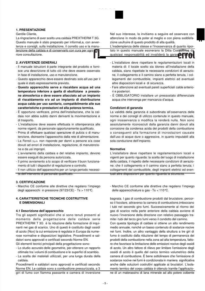
Le caldaie PREXTHERM T 3G sono a combustione pressuriz-zata, a 3 giri di fumo con fiamma passante e camera di inversio-ne bagnata. I gas di combustione prodotti dal bruciatore, percor-so il focolare, attraverso la camera di inversione, imboccano itubi nel secondo giro fumi. Successivamente al ritorno dei gasdi scarico nella parte anteriore della caldaia avviene di nuovo
l’inversione della direzione con relativo passaggio tramite i tubidel terzo giro fumi verso il condotto del camino. La camera dicombustione durante il funzionamento del bruciatore è semprein pressione. Per il valore di questa pressione vedere la tabellaDATI TECNICI, alla colonna Perdite di carico lato fumi. Il canaleda fumo ed il raccordo alla canna fumaria devono essere realiz-
zati in conformità alle Norme ed alla Legislazione vigente, concondotti rigidi, resistenti alla temperatura, alla condensa, allesollecitazioni meccaniche e a tenuta (Fig. 1-2).
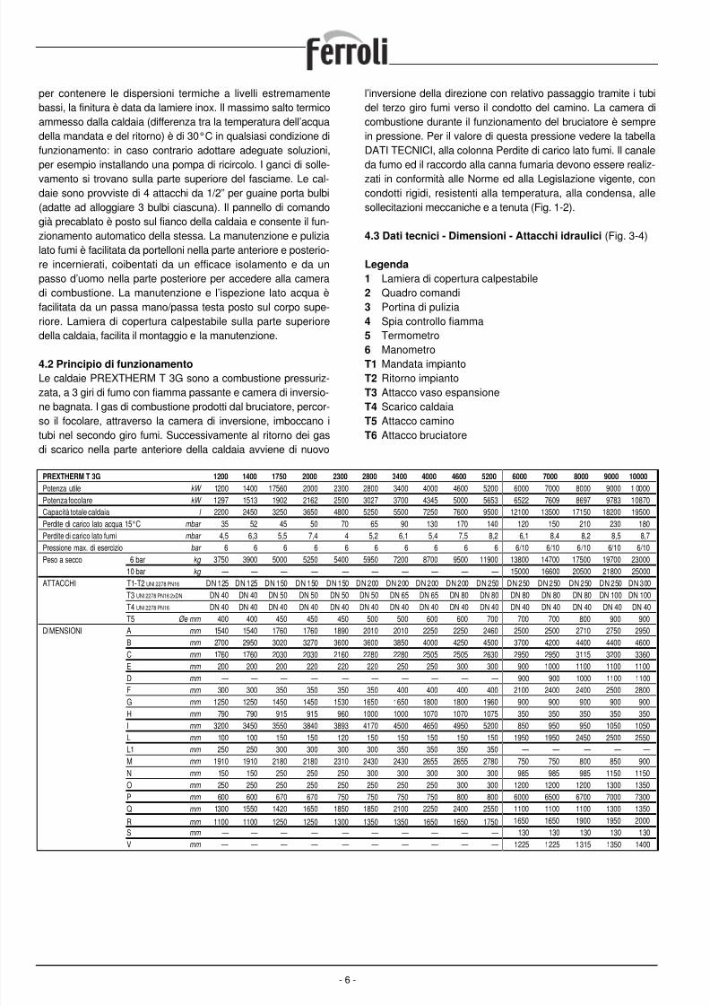
4.3 Dati tecnici - Dimensioni - Attacchi idraulici (Fig. 3-4)
Legenda
1 Lamiera di copertura calpestabile2 Quadro comandi3 Portina di pulizia4 Spia controllo fiamma5 Termometro
6 ManometroT1 Mandata impiantoT2 Ritorno impiantoT3 Attacco vaso espansioneT4 Scarico caldaiaT5 Attacco caminoT6 Attacco bruciatore
- 6 -
PREXTHERM T 3G 1200 1400 1750 2000 2300 2800 3400 4000 4600 5200 6000 7000 8000 9000 10000
Potenza utile kW 1200 1400 17560 2000 2300 2800 3400 4000 4600 5200 6000 7000 8000 9000 1 0000
Potenza focolare kW 1297 1513 1902 2162 2500 3027 3700 4345 5000 5653 6522 7609 8697 9783 10870
Capacità totale caldaia l 2200 2450 3250 3650 4800 5250 5500 7250 7600 9500 12100 13500 17150 18200 19500
Perdite di carico lato acqua 15°C mbar 35 52 45 50 70 65 90 130 170 140 120 150 210 230 180
Perdite di carico lato fumi mbar 4,5 6,3 5,5 7,4 4 5,2 6,1 5,4 7,5 8,2 6,1 8,4 8,2 8,5 8,7
Pressione max. di esercizio bar 6 6 6 6 6 6 6 6 6 6 6/10 6/10 6/10 6/10 6/10
Peso a secco 6 bar kg 3750 3900 5000 5250 5400 5950 7200 8700 9500 11900 13800 14700 17500 19700 23000
10 bar kg — — — — — — — — — — 15000 16600 20500 21800 25000
ATTACCHI T1-T2 UNI 2278 PN16 DN 125 DN 125 DN 150 DN 150 DN 150 DN 200 DN 200 DN 200 DN 200 DN 250 DN 250 DN 250 DN 250 DN 250 DN 300
T3 UNI 2278 PN16 2xDN DN 40 DN 40 DN 50 DN 50 DN 50 DN 50 DN 65 DN 65 DN 80 DN 80 DN 80 DN 80 DN 80 DN 100 DN 100
T4 UNI 2278 PN16 DN 40 DN 40 DN 40 DN 40 DN 40 DN 40 DN 40 DN 40 DN 40 DN 40 DN 40 DN 40 DN 40 DN 40 DN 40
T5 Øe mm 400 400 450 450 450 500 500 600 600 700 700 700 800 900 900
DIMENSIONI A mm 1540 1540 1760 1760 1890 2010 2010 2250 2250 2460 2500 2500 2710 2750 2950
B mm 2700 2950 3020 3270 3600 3600 3850 4000 4250 4500 3700 4200 4400 4400 4600
C mm 1760 1760 2030 2030 2160 2280 2280 2505 2505 2630 2950 2950 3115 3200 3360
E mm 200 200 200 220 220 220 250 250 300 300 900 1000 1100 1100 1100
D mm — — — — — — — — — — 900 900 1000 1100 1100
F mm 300 300 350 350 350 350 400 400 400 400 2100 2400 2400 2500 2800
G mm 1250 1250 1450 1450 1530 1650 1650 1800 1800 1960 900 900 900 900 900H mm 790 790 915 915 960 1000 1000 1070 1070 1075 350 350 350 350 350
I mm 3200 3450 3550 3840 3893 4170 4500 4650 4950 5200 850 950 950 1050 1050
L mm 100 100 150 150 120 150 150 150 150 150 1950 1950 2450 2500 2550
L1 mm 250 250 300 300 300 300 350 350 350 350 — — — — —
M mm 1910 1910 2180 2180 2310 2430 2430 2655 2655 2780 750 750 800 850 900
N mm 150 150 250 250 250 300 300 300 300 300 985 985 985 1150 1150
O mm 250 250 250 250 250 250 250 250 300 300 1200 1200 1200 1300 1350
P mm 600 600 670 670 750 750 750 750 800 800 6000 6500 6700 7000 7300
Q mm 1300 1550 1420 1650 1850 1850 2100 2250 2400 2550 1100 1100 1100 1300 1350
R mm 1100 1100 1250 1250 1300 1350 1350 1650 1650 1750 1650 1650 1900 1950 2000
S mm — — — — — — — — — — 130 130 130 130 130
V mm — — — — — — — — — — 1225 1225 1315 1350 1400
8/13/2019 1657_prextherm t 3g It+Gb
http://slidepdf.com/reader/full/1657prextherm-t-3g-itgb 7/36
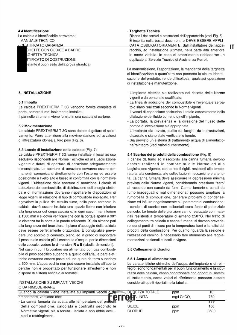
4.4 Identificazione
La caldaia è identificabile attraverso:- MANUALE TECNICO- CERTIFICATO GARANZIA- ETICHETTE CON CODICE A BARRE- TARGHETTA TECNICA
- CERTIFICATO DI COSTRUZIONE(attestante il buon esito della prova idraulica)
- Targhetta Tecnica
Riporta i dati tecnici e prestazioni dell’apparecchio (vedi Fig. 5).È inserita nella busta documenti e DEVE ESSERE APPLI-CATA OBBLIGATORIAMENTE, dall’installatore dell’appa-recchio, ad installazione ultimata, nella parte alta anteriorein modo visibile. In caso di smarrimento richiederne un
duplicato al Servizio Tecnico di Assistenza Ferroli.
La manomissione, l’asportazione, la mancanza della targhettadi identificazione o quant’altro non permetta la sicura identifi-cazione del prodotto, rende difficoltosa qualsiasi operazionedi installazione e manutenzione.
- 7 -
IT
5. INSTALLAZIONE
5.1 Imballo
Le caldaie PREXTHERM T 3G vengono fornite complete diporta, camera fumo, isolamento installati.
Il pannello strumenti viene fornito in una scatola di cartone.
5.2 Movimentazione
Le caldaie PREXTHERM T 3G sono dotate di golfare di solle-vamento. Porre attenzione alla movimentazione ed avvalersidi attrezzatura idonea ai loro pesi (Fig. 6).
5.3 Locale di installazione della caldaia (Fig. 7)Le caldaie PREXTHERM T 3G vanno installate in locali ad usoesclusivo rispondenti alle Norme Tecniche ed alla Legislazionevigente e dotati di aperture di aerazione adeguatamentedimensionate. Le aperture di aerazione dovranno essere per-manenti, comunicanti direttamente con l’esterno ed essereposizionate a livello alto e basso in conformità con le normativevigenti. L’ubicazione delle aperture di aerazione, i circuiti diadduzione del combustibile, di distribuzione dell’energia elettri-ca e di illuminazione dovranno rispettare le disposizioni dilegge vigenti in relazione al tipo di combustibile impiegato. Peragevolare la pulizia del circuito fumo, nella parte anteriore lacaldaia, dovrà essere lasciato uno spazio libero non inferiorealla lunghezza del corpo caldaia e, in ogni caso, mai inferiorea 1300 mm e si dovrà verificare che con la porta/e aperta a 90°la distanza tra la porta e la parete adiacente X, sia almeno parialla lunghezza del bruciatore. Il piano d’appoggio della caldaiadeve essere perfettamente orizzontale. È consigliabile preve-
dere uno zoccolo di cemento, piano, ed in grado di sopportareil peso totale caldaia più il contenuto d’acqua, per le dimensionidello zoccolo, vedere le dimensioni R x B (tabella dimensioni).Nel caso in cui il bruciatore sia alimentato con gas combusti-bile di peso specifico superiore a quello dell’aria, le parti elet-triche dovranno essere poste ad una quota da terra superiorea 500 mm. L’apparecchio non può essere installato all’apertoperché non è progettato per funzionare all’esterno e nondispone di sistemi antigelo automatici.
INSTALLAZIONE SU IMPIANTI VECCHIO DA RIMODERNARE
Quando la caldaia viene installata su impianti vecchi o darimodernare, verificare che:- La canna fumaria sia adatta alle temperature dei prodotti
della combustione, calcolata e costruita secondo leNormative vigenti, sia a tenuta , isolata e non abbia occlu-sioni o restringimenti.
- L’impianto elettrico sia realizzato nel rispetto delle Normevigenti e da personale qualificato.
- La linea di adduzione del combustibile e l’eventuale serba-toio siano realizzati secondo le Norme vigenti.
- Il vaso/i di espansione assicurino il totale assorbimento della
dilatazione del fluido contenuto nell’impianto.- La portata, la prevalenza e la direzione del flusso dellepompe di circolazione sia appropriata.
- L’impianto sia lavato, pulito da fanghi, da incrostazioni,disaerato e siano state verificate le tenute.
- Sia previsto un sistema di trattamento acqua di alimentazio-ne/reintegro (vedi valori di riferimento).
5.4 Scarico dei prodotti della combustione (Fig. 8)Il canale da fumo ed il raccordo alla canna fumaria devonoessere realizzati in conformità al le Norme ed al laLegislazione vigente, con condotti rigidi, resistenti alla tempe-ratura, alla condensa, alle sollecitazioni meccaniche e a tenu-ta. La canna fumaria deve assicurare la depressione minimaprevista dalle Norme vigenti, considerando pressione “zero”al raccordo con canale da fumi. Canne fumarie e canali dafumo inadeguati o mal dimensionati possono ampliare larumorosità di combustione, generare problemi di condensa-zione ed influire negativamente sui parametri di combustione.I condotti di scarico non coibentati sono fonte di potenzialepericolo. Le tenute delle giunzioni vanno realizzate con mate-riali resistenti a temperature di almeno 250°C. Nel tratto dicollegamento tra caldaia e canna fumaria, si devono prevede-re idonei punti di misura per la temperatura fumi e l’analisi deiprodotti della combustione. Per quanto riguarda la sezione e
l’altezza del camino, è necessario fare riferimento alle regola-mentazioni nazionali e locali in vigore.
5.5 Collegamenti idraulici
5.5.1 Acqua di alimentazione
Le caratteristiche chimiche dell’acqua dell’impianto e di rein-tegro, sono fondamentali per il buon funzionamento e la sicu-rezza della caldaia, vanno condizionate con opportuni sistemidi trattamento, come valori di riferimento possono essereconsiderati quelli riportati nella tabella.
DUREZZA TOTALE ppm 10ALCALINITÀ mg/l CaCO3 750PH 8÷9SILICE ppm 100CLORURI ppm 3500
8/13/2019 1657_prextherm t 3g It+Gb
http://slidepdf.com/reader/full/1657prextherm-t-3g-itgb 8/36
È assolutamente indispensabile il trattamento dell’acqua uti-lizzata per l’impianto di riscaldamento nei seguenti casi:- Impianti molto estesi- Acqua con elevata durezza- Frequenti immissioni di acqua di reintegro nell’impiantoNel caso si rendesse necessario lo svuotamento parziale o
totale dell’impianto, si prescrive di effettuare il successivo riem-pimento con acqua trattata. Per il controllo dell’entità dei reinte-gri si consiglia di installare sulla tubazione un contatore. I feno-meni più comuni che si verificano negli impianti termici sono:- Incrostazioni di calcare
Il calcare si concentra nei punti dove maggiore è la temperaturadi parete. Le incrostazioni calcaree a causa della loro bassa con-duttività termica riducono lo scambio termico così che la presen-za di pochi millimetri, contrastano lo scambio termico tra i fumi el’acqua, comportando un aumento della temperatura delle partiesposte alla fiamma e quindi rotture (cricche) sulla piastra tubiera.
- Corrosione lato acquaLa corrosione delle superfici metalliche della caldaia latoacqua è dovuta al passaggio in soluzione del ferro attraversoi suoi ioni. In questo processo ha molta importanza la pre-senza dei gas disciolti ed in particolare dell’ossigeno e anidri-de carbonica. In presenza di acque addolcite e/o deminera-lizzate si è al riparo da fenomeni di incrostazione, ma nonaltrettanto per quanto riguarda le corrosioni, è necessarioquindi condizionare l’acqua con inibitori di processi corrosivi.
5.5.2 Tubazioni mandata/ritorno impianto
Le dimensioni delle tubazioni di mandata e ritorno sono indi-cate per ogni modello di caldaia nella tabella DIMENSIONI.Assicurarsi che sull’impianto ci sia un numero sufficiente disfiati. Gli attacchi della caldaia non devono essere sollecitatidal peso delle tubazioni d’allacciamento all’impianto, installa-re pertanto appositi supporti.
5.5.3 Tubazioni riempimento/scarico impianto
Per il riempimento e lo scarico della caldaia un rubinetto puòessere collegato all’attacco T4 che si trova nella posteriorevedi disegno DIMENSIONI.
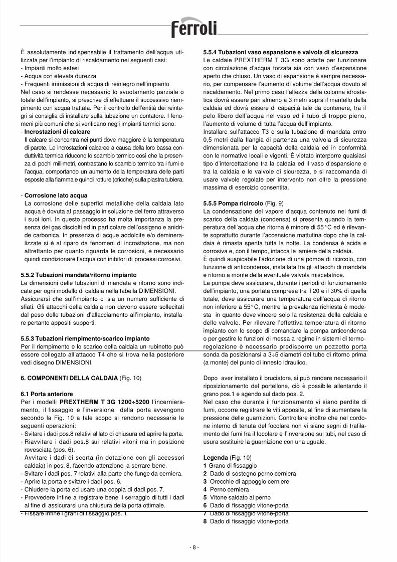
5.5.4 Tubazioni vaso espansione e valvola di sicurezza
Le caldaie PREXTHERM T 3G sono adatte per funzionarecon circolazione d’acqua forzata sia con vaso d’espansioneaperto che chiuso. Un vaso di espansione è sempre necessa-rio, per compensare l’aumento di volume dell’acqua dovuto alriscaldamento. Nel primo caso l’altezza della colonna idrosta-
tica dovrà essere pari almeno a 3 metri sopra il mantello dellacaldaia ed dovrà essere di capacità tale da contenere, tra ilpelo libero dell’acqua nel vaso ed il tubo di troppo pieno,l’aumento di volume di tutta l’acqua dell’impianto.Installare sull’attacco T3 o sulla tubazione di mandata entro0,5 metri dalla flangia di partenza una valvola di sicurezzadimensionata per la capacità della caldaia ed in conformitàcon le normative locali e vigenti. È vietato interporre qualsiasitipo d’intercettazione tra la caldaia ed il vaso d’espansione etra la caldaia e le valvole di sicurezza, e si raccomanda diusare valvole regolate per intervento non oltre la pressionemassima di esercizio consentita.
5.5.5 Pompa ricircolo (Fig. 9)La condensazione del vapore d’acqua contenuto nei fumi discarico della caldaia (condensa) si presenta quando la tem-peratura dell’acqua che ritorna è minore di 55°C ed è rilevan-te soprattutto durante l’accensione mattutina dopo che la cal-daia è rimasta spenta tutta la notte. La condensa è acida ecorrosiva e, con il tempo, intacca le lamiere della caldaia.È quindi auspicabile l’adozione di una pompa di ricircolo, confunzione di anticondensa, installata tra gli attacchi di mandatae ritorno a monte della eventuale valvola miscelatrice.La pompa deve assicurare, durante i periodi di funzionamentodell’impianto, una portata compresa tra il 20 e il 30% di quellatotale, deve assicurare una temperatura dell’acqua di ritornonon inferiore a 55°C, mentre la prevalenza richiesta è mode-sta in quanto deve vincere solo la resistenza della caldaia edelle valvole. Per rilevare l’effettiva temperatura di ritornoimpianto con lo scopo di comandare la pompa anticondensao per gestire le funzioni di messa a regime in sistemi di termo-regolazione è necessario predisporre un pozzetto portasonda da posizionarsi a 3÷5 diametri del tubo di ritorno prima(a monte) del punto di innesto idraulico.
- 8 -
6. COMPONENTI DELLA CALDAIA (Fig. 10)
6.1 Porta anteriorePer i modelli PREXTHERM T 3G 1200÷5200 l’incerniera-mento, il fissaggio e l’inversione della porta avvengonosecondo la Fig. 10 a tale scopo si rendono necessarie leseguenti operazioni:- Svitare i dadi pos.8 relativi al lato di chiusura ed aprire la porta.- Riavvitare i dadi pos.8 sui relativi vitoni ma in posizione
rovesciata (pos. 6).- Avvitare i dadi di scorta (in dotazione con gli accessori
caldaia) in pos. 8, facendo attenzione a serrare bene.- Svitare i dadi pos. 7 relativi alla parte che funge da cerniera.- Aprire la porta e svitare i dadi pos. 6.
- Chiudere la porta ed usare una coppia di dadi pos. 7.- Provvedere infine a registrare bene il serraggio di tutti i dadial fine di assicurarsi una chiusura della porta ottimale.
- Fissare infine i grani di fissaggio pos. 1.
Dopo aver installato il bruciatore, si può rendere necessario ilriposizionamento del portellone, ciò è possibile allentando il
grano pos.1 e agendo sul dado pos. 2.Nel caso che durante il funzionamento vi siano perdite difumi, occorre registrare le viti apposite, al fine di aumentare lapressione delle guarnizioni. Controllare inoltre che nel cordo-ne interno di tenuta del focolare non vi siano segni di trafila-mento dei fumi fra il focolare e l’inversione sui tubi, nel caso diusura sostituire la guarnizione con una uguale.
Legenda (Fig. 10)1 Grano di fissaggio2 Dado di sostegno perno cerniera3 Orecchie di appoggio cerniere
4 Perno cerniera5 Vitone saldato al perno6 Dado di fissaggio vitone-porta7 Dado di fissaggio vitone-porta8 Dado di fissaggio vitone-porta
8/13/2019 1657_prextherm t 3g It+Gb
http://slidepdf.com/reader/full/1657prextherm-t-3g-itgb 9/36
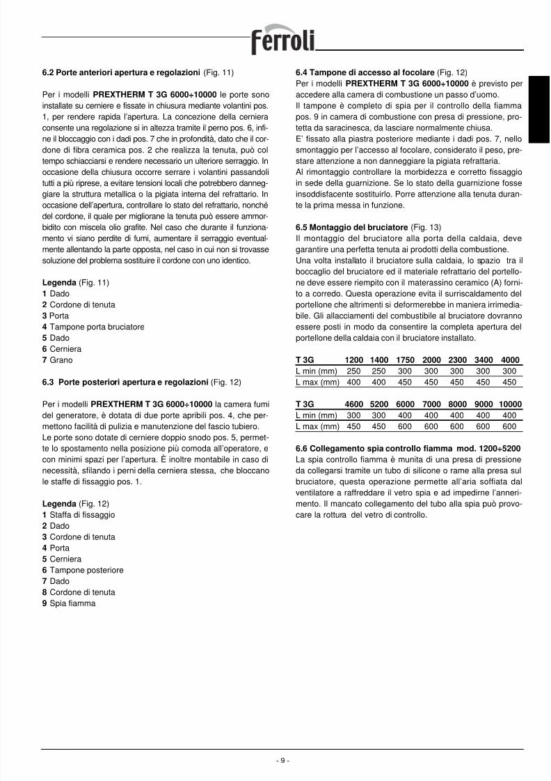
6.2 Porte anteriori apertura e regolazioni (Fig. 11)
Per i modelli PREXTHERM T 3G 6000÷10000 le porte sonoinstallate su cerniere e fissate in chiusura mediante volantini pos.1, per rendere rapida l’apertura. La concezione della cernieraconsente una regolazione si in altezza tramite il perno pos. 6, infi-
ne il bloccaggio con i dadi pos. 7 che in profondità, dato che il cor-done di fibra ceramica pos. 2 che realizza la tenuta, può coltempo schiacciarsi e rendere necessario un ulteriore serraggio. Inoccasione della chiusura occorre serrare i volantini passandolitutti a più riprese, a evitare tensioni locali che potrebbero danneg-giare la struttura metallica o la pigiata interna del refrattario. Inoccasione dell’apertura, controllare lo stato del refrattario, nonchédel cordone, il quale per migliorane la tenuta può essere ammor-bidito con miscela olio grafite. Nel caso che durante il funziona-mento vi siano perdite di fumi, aumentare il serraggio eventual-mente allentando la parte opposta, nel caso in cui non si trovassesoluzione del problema sostituire il cordone con uno identico.
Legenda (Fig. 11)1 Dado2 Cordone di tenuta3 Porta4 Tampone porta bruciatore5 Dado6 Cerniera7 Grano
6.3 Porte posteriori apertura e regolazioni (Fig. 12)
Per i modelli PREXTHERM T 3G 6000÷10000 la camera fumidel generatore, è dotata di due porte apribili pos. 4, che per-mettono facilità di pulizia e manutenzione del fascio tubiero.Le porte sono dotate di cerniere doppio snodo pos. 5, permet-te lo spostamento nella posizione più comoda all’operatore, econ minimi spazi per l’apertura. È inoltre montabile in caso dinecessità, sfilando i perni della cerniera stessa, che bloccanole staffe di fissaggio pos. 1.
Legenda (Fig. 12)1 Staffa di fissaggio2 Dado3 Cordone di tenuta
4 Porta5 Cerniera6 Tampone posteriore7 Dado8 Cordone di tenuta9 Spia fiamma
6.4 Tampone di accesso al focolare (Fig. 12)Per i modelli PREXTHERM T 3G 6000÷10000 è previsto peraccedere alla camera di combustione un passo d’uomo.Il tampone è completo di spia per il controllo della fiammapos. 9 in camera di combustione con presa di pressione, pro-tetta da saracinesca, da lasciare normalmente chiusa.
E’ fissato alla piastra posteriore mediante i dadi pos. 7, nellosmontaggio per l’accesso al focolare, considerato il peso, pre-stare attenzione a non danneggiare la pigiata refrattaria.Al rimontaggio controllare la morbidezza e corretto fissaggioin sede della guarnizione. Se lo stato della guarnizione fosseinsoddisfacente sostituirlo. Porre attenzione alla tenuta duran-te la prima messa in funzione.
6.5 Montaggio del bruciatore (Fig. 13)Il montaggio del bruciatore alla porta della caldaia, devegarantire una perfetta tenuta ai prodotti della combustione.Una volta installato il bruciatore sulla caldaia, lo spazio tra il
boccaglio del bruciatore ed il materiale refrattario del portello-ne deve essere riempito con il materassino ceramico (A) forni-to a corredo. Questa operazione evita il surriscaldamento delportellone che altrimenti si deformerebbe in maniera irrimedia-bile. Gli allacciamenti del combustibile al bruciatore dovrannoessere posti in modo da consentire la completa apertura delportellone della caldaia con il bruciatore installato.
T 3G 1200 1400 1750 2000 2300 3400 4000
L min (mm) 250 250 300 300 300 300 300L max (mm) 400 400 450 450 450 450 450
T 3G 4600 5200 6000 7000 8000 9000 10000
L min (mm) 300 300 400 400 400 400 400L max (mm) 450 450 600 600 600 600 600
6.6 Collegamento spia controllo fiamma mod. 1200÷5200
La spia controllo fiamma è munita di una presa di pressioneda collegarsi tramite un tubo di silicone o rame alla presa sulbruciatore, questa operazione permette all’aria soffiata dalventilatore a raffreddare il vetro spia e ad impedirne l’anneri-mento. Il mancato collegamento del tubo alla spia può provo-care la rottura del vetro di controllo.
- 9 -
IT
8/13/2019 1657_prextherm t 3g It+Gb
http://slidepdf.com/reader/full/1657prextherm-t-3g-itgb 10/36
7. PANNELLO STRUMENTI STANDARD
7.1 Pannello (Fig. 14)Il pannello strumenti in dotazione, realizzato in materiale pla-stico con grado di protezione IP40, accoglie la strumentazio-ne di regolazione e sicurezza.
L’impianto elettrico a bordo caldaia deve essere:- progettato e realizzato da personale qualificato e collegato
ad un impianto di messa a terra nel rispetto delle norme dilegge vigenti.
- adeguato alla potenza massima assorbita dalla caldaia concavi elettrici di sezione idonea.
I cavi di alimentazione e collegamento al bruciatore devonoavere il conduttore di terra alcuni mm più lungo degli altri con-duttori dello stesso cavo. Per i collegamenti tra bruciatore,pannello elettrico e alimentazione si consiglia l’utilizzo di cavoH07 RN-F per collegamenti con posa a vista. Per altri tipi diinstallazione o per particolari situazioni ambientali si consiglia
di consultare le normative vigenti. La formazione e il diametrodei conduttori va calcolata in base all’assorbimento del brucia-tore. Per accedere agli strumenti, ruotare il pannello frontale(A). Per accedere alla morsettiera e per svolgere i capillari deitermostati e del termometro, togliere il pannello superiore (B)previo smontaggio delle 2 viti laterali (C). I termostati di regola-zione (12-13) sono tarabili dall’utente mediante manopola fron-tale. Il termostato di sicurezza (4) è a taratura fissa ed ha unriarmo manuale come previsto dal D.M. 1/12/75 raccolta R.È obbligatorio:- l’impiego di un interruttore magnetotermico bipolare, sezio-
natore di linea, conforme alle Norme CEI-EN (apertura deicontatti di almeno 3 mm)
- rispettare il collegamento L1 (Fase) - N (Neutro)
- utilizzare cavi con sezione maggiore o uguale a 1,5 mm2,completi di puntalini capicorda.
- riferirsi agli schemi elettrici del presente libretto per qualsiasiintervento di natura elettrica.
- realizzare un efficace collegamento di terra.- è vietato l’uso dei tubi dell’acqua per la messa a terra
dell’apparecchio.Il costruttore non è responsabile di eventuali danni causatidalla mancanza di messa a terra dell’apparecchio e dall’inos-servanza di quanto riportato negli schemi elettrici.Per la messa a terra del corpo caldaia è previsto sulla testataanteriore un punto di connessione.
7.2 Vista frontale pannello (Fig. 15)
Legenda
1 Interruttore accensione circolatore2 Interruttore accensione bruciatore
3 Interruttore accensione caldaia4 Pulsante Test5 Pulsante ripristino pressostato di sicurezza6 Temperatura acqua caldaia7 Spia led caldaia accesa8 Spia led 1a fiamma bruciatore9 Spia led 2a fiamma bruciatore
10 Spia led blocco bruciatore11 Spia led pressostato di sicurezza12 Termostato TR1 regolazione 2a fiamma caldaia13 Termostato TR1 regolazione 1a fiamma caldaia14 Predisposizione per termoregolazione
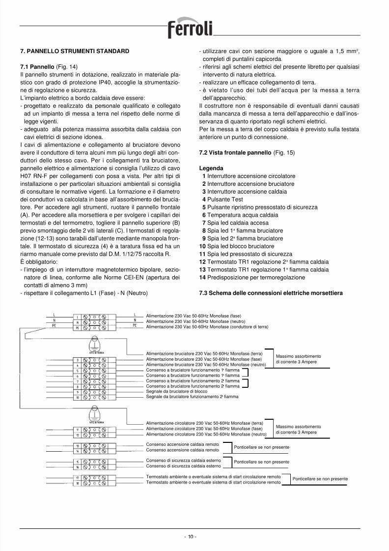
7.3 Schema delle connessioni elettriche morsettiera
- 10 -
Alimentazione 230 Vac 50-60Hz Monofase (fase)Alimentazione 230 Vac 50-60Hz Monofase (neutro)Alimentazione 230 Vac 50-60Hz Monofase (conduttore di terra)
Alimentazione bruciatore 230 Vac 50-60Hz Monofase (terra)Alimentazione bruciatore 230 Vac 50-60Hz Monofase (fase)Alimentazione bruciatore 230 Vac 50-60Hz Monofase (neutro)Consenso a bruciatore funzionamento 1a fiammaConsenso a bruciatore funzionamento 1a fiammaConsenso a bruciatore funzionamento 2a fiamma
Consenso a bruciatore funzionamento 2a fiammaSegnale da bruciatore di bloccoSegnale da bruciatore funzionamento 2a fiamma
Massimo assorbimentodi corrente 3 Ampere
Alimentazione circolatore 230 Vac 50-60Hz Monofase (terra)Alimentazione circolatore 230 Vac 50-60Hz Monofase (fase)Alimentazione circolatore 230 Vac 50-60Hz Monofase (neutro)
Massimo assorbimentodi corrente 3 Ampere
Consenso accensione caldaia remotoConsenso accensione caldaia remoto
Ponticellare se non presente
Consenso di sicurezza caldaia esternoConsenso di sicurezza caldaia esterno
Ponticellare se non presente
Termostato ambiente o eventuale sistema di start circolazione remoto
Termostato ambiente o eventuale sistema di start circolazione remoto
Ponticellare se non presente
8/13/2019 1657_prextherm t 3g It+Gb
http://slidepdf.com/reader/full/1657prextherm-t-3g-itgb 11/36
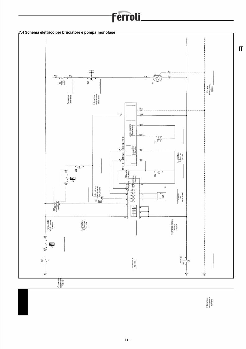
7.4 Schema elettrico per bruciatore e pompa monofase
- 11 -
IT
C o n s e n s o
a c c e n s i o n e
r e m o t o
T e r m o s t a t o
d i s i c u r e z z a
C a l d a i a
C o n s e n s o
d i s i c u r e z z a
e s t e r n o
T e r m o s t a t o
1 a f i a m m a
C a l d a i a
I n t e r r u t t o r e
a c c e n s i o n e
b r u c i a t o r e
C O L L E G A M E N T I B R U C I A T O R E
B l o c c o
B r u c i a t o r e
S e c o n d a
f i a m m a
C o n s e n s o
1 a
f i a m m a
C o n s e n s o
2 a f i a m m a
A l i m e n t a z i o n e
B r u c i a t o r e
T e r m o s t a t o
a m b i e n t e
I n t e r r u t t o r e
a c c e n s i o n e
c i r c o l a t o r e
P o m p a
c i r c o l a z i o n e
a c q u a
T e r m o s t a t o
2 a f i a m m a
C a l d a i a
P u l s a n t e
t e s t
t e r m o s t a t o
T e r m o r e s i s t e n z a
a c q u a
c a l d a i a
I n t e r r u t t o r e
a c c e n s i o n e
c a l d a i a
T e r m o m e t r o
d i g i t a l e
8/13/2019 1657_prextherm t 3g It+Gb
http://slidepdf.com/reader/full/1657prextherm-t-3g-itgb 12/36
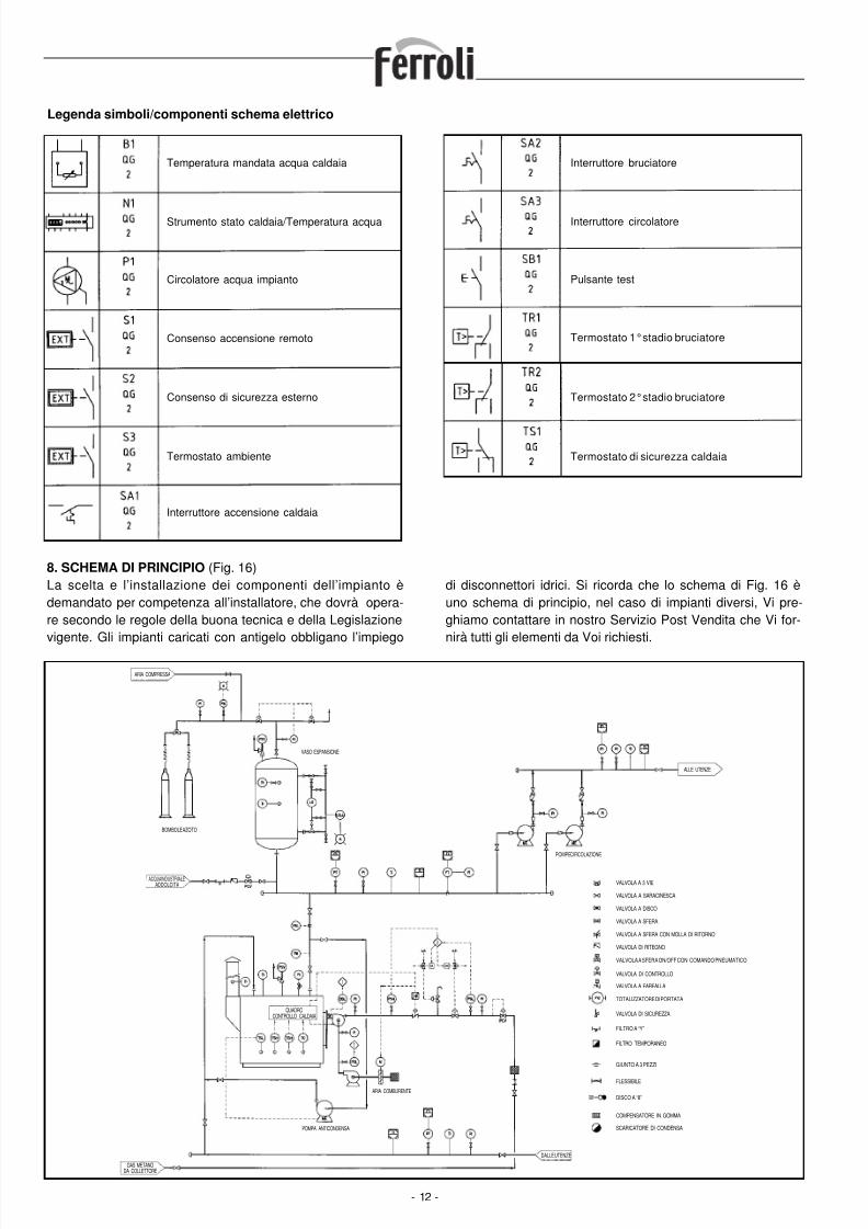
Legenda simboli/componenti schema elettrico
- 12 -
Temperatura mandata acqua caldaia
Strumento stato caldaia/Temperatura acqua
Circolatore acqua impianto
Consenso accensione remoto
Consenso di sicurezza esterno
Termostato ambiente
Interruttore accensione caldaia
Interruttore bruciatore
Interruttore circolatore
Pulsante test
Termostato 1°stadio bruciatore
Termostato 2°stadio bruciatore
Termostato di sicurezza caldaia
ARIA COMPRESSA
BOMBOLE AZOTO
ACQUA INDUSTRIALEADDOLCITA
VASO ESPANSIONE
POMPE CIRCOLAZIONE
ALLE UTENZE
QUADROCONTROLLO CALDAIA
POMPA ANTICONDENSA
ARIA COMBURENTE
GAS METANODA COLLETTORE
DALLE UTENZE
VALVOLA A 3 VIE
VALVOLA A SARACINESCA
VALVOLA A DISCO
VALVOLA A SFERA
VALVOLA A SFERA CON MOLLA DI RITORNO
VALVOLA DI RITEGNO
VALVOLA A SFERA ON/OFF CON COMANDO PNEUMATICO
VALVOLA DI CONTROLLO
VALVOLA A FARFALLA
TOTALIZZATORE DI PORTATA
VALVOLA DI SICUREZZA
FILTRO A “Y”
FILTRO TEMPORANEO
GIUNTO A 3 PEZZI
FLESSIBILE
DISCO A “8”
COMPENSATORE IN GOMMA
SCARICATORE DI CONDENSA
8. SCHEMA DI PRINCIPIO (Fig. 16)La scelta e l’installazione dei componenti dell’impianto èdemandato per competenza all’installatore, che dovrà opera-re secondo le regole della buona tecnica e della Legislazionevigente. Gli impianti caricati con antigelo obbligano l’impiego
di disconnettori idrici. Si ricorda che lo schema di Fig. 16 èuno schema di principio, nel caso di impianti diversi, Vi pre-ghiamo contattare in nostro Servizio Post Vendita che Vi for-nirà tutti gli elementi da Voi richiesti.
8/13/2019 1657_prextherm t 3g It+Gb
http://slidepdf.com/reader/full/1657prextherm-t-3g-itgb 13/36
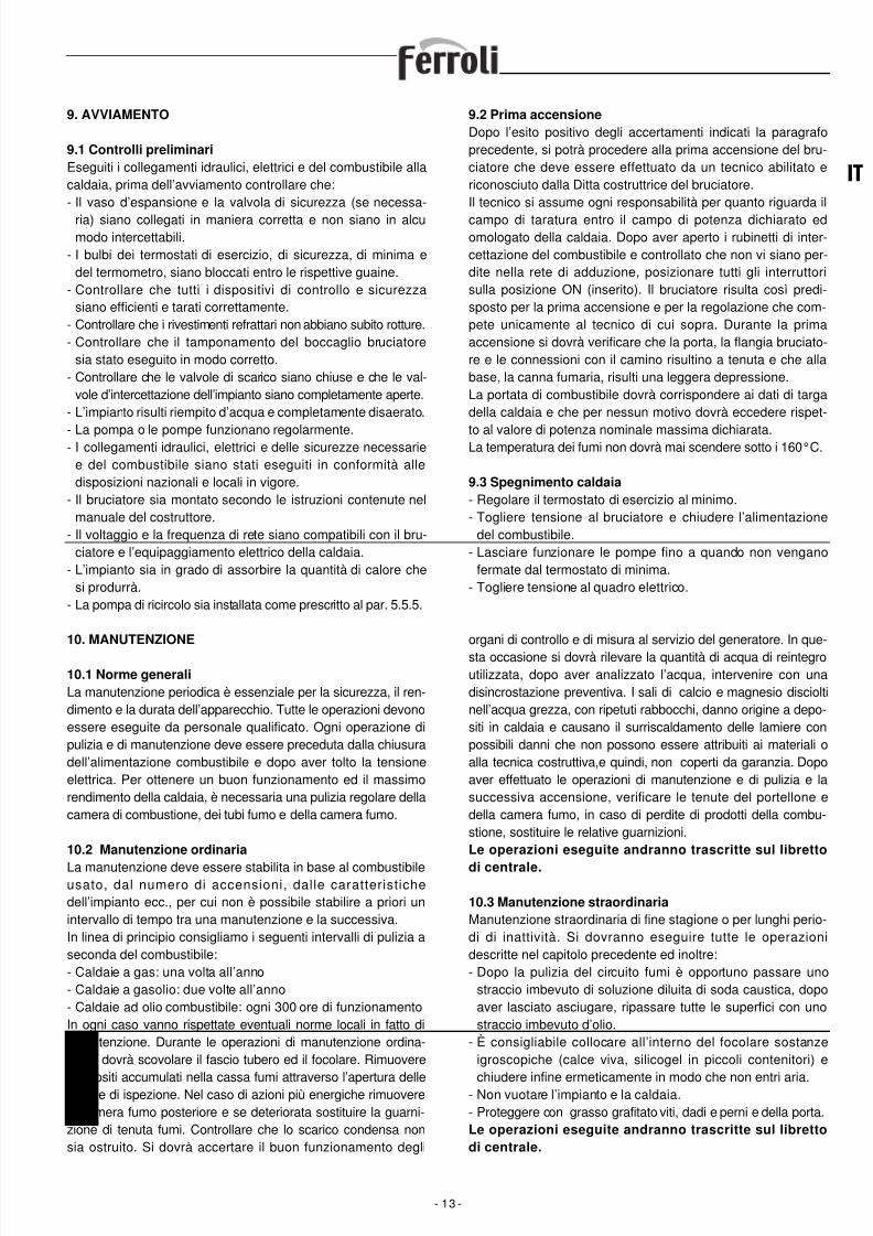
9. AVVIAMENTO
9.1 Controlli preliminari
Eseguiti i collegamenti idraulici, elettrici e del combustibile allacaldaia, prima dell’avviamento controllare che:- Il vaso d’espansione e la valvola di sicurezza (se necessa-
ria) siano collegati in maniera corretta e non siano in alcumodo intercettabili.
- I bulbi dei termostati di esercizio, di sicurezza, di minima edel termometro, siano bloccati entro le rispettive guaine.
- Controllare che tutti i dispositivi di controllo e sicurezzasiano efficienti e tarati correttamente.
- Controllare che i rivestimenti refrattari non abbiano subito rotture.- Controllare che il tamponamento del boccaglio bruciatore
sia stato eseguito in modo corretto.- Controllare che le valvole di scarico siano chiuse e che le val-
vole d’intercettazione dell’impianto siano completamente aperte.- L’impianto risulti riempito d’acqua e completamente disaerato.
- La pompa o le pompe funzionano regolarmente.- I collegamenti idraulici, elettrici e delle sicurezze necessariee del combustibile siano stati eseguiti in conformità alledisposizioni nazionali e locali in vigore.
- Il bruciatore sia montato secondo le istruzioni contenute nelmanuale del costruttore.
- Il voltaggio e la frequenza di rete siano compatibili con il bru-ciatore e l’equipaggiamento elettrico della caldaia.
- L’impianto sia in grado di assorbire la quantità di calore chesi produrrà.
- La pompa di ricircolo sia installata come prescritto al par. 5.5.5.
9.2 Prima accensione
Dopo l’esito positivo degli accertamenti indicati la paragrafoprecedente, si potrà procedere alla prima accensione del bru-ciatore che deve essere effettuato da un tecnico abilitato ericonosciuto dalla Ditta costruttrice del bruciatore.Il tecnico si assume ogni responsabilità per quanto riguarda il
campo di taratura entro il campo di potenza dichiarato edomologato della caldaia. Dopo aver aperto i rubinetti di inter-cettazione del combustibile e controllato che non vi siano per-dite nella rete di adduzione, posizionare tutti gli interruttorisulla posizione ON (inserito). Il bruciatore risulta così predi-sposto per la prima accensione e per la regolazione che com-pete unicamente al tecnico di cui sopra. Durante la primaaccensione si dovrà verificare che la porta, la flangia bruciato-re e le connessioni con il camino risultino a tenuta e che allabase, la canna fumaria, risulti una leggera depressione.La portata di combustibile dovrà corrispondere ai dati di targadella caldaia e che per nessun motivo dovrà eccedere rispet-
to al valore di potenza nominale massima dichiarata.La temperatura dei fumi non dovrà mai scendere sotto i 160°C.
9.3 Spegnimento caldaia
- Regolare il termostato di esercizio al minimo.- Togliere tensione al bruciatore e chiudere l’alimentazione
del combustibile.- Lasciare funzionare le pompe fino a quando non vengano
fermate dal termostato di minima.- Togliere tensione al quadro elettrico.
- 13 -
IT
10. MANUTENZIONE
10.1 Norme generali
La manutenzione periodica è essenziale per la sicurezza, il ren-dimento e la durata dell’apparecchio. Tutte le operazioni devonoessere eseguite da personale qualificato. Ogni operazione dipulizia e di manutenzione deve essere preceduta dalla chiusuradell’alimentazione combustibile e dopo aver tolto la tensioneelettrica. Per ottenere un buon funzionamento ed il massimorendimento della caldaia, è necessaria una pulizia regolare dellacamera di combustione, dei tubi fumo e della camera fumo.
10.2 Manutenzione ordinaria
La manutenzione deve essere stabilita in base al combustibileusato, dal numero di accensioni, dalle caratteristichedell’impianto ecc., per cui non è possibile stabilire a priori unintervallo di tempo tra una manutenzione e la successiva.In linea di principio consigliamo i seguenti intervalli di pulizia aseconda del combustibile:- Caldaie a gas: una volta all’anno- Caldaie a gasolio: due volte all’anno- Caldaie ad olio combustibile: ogni 300 ore di funzionamentoIn ogni caso vanno rispettate eventuali norme locali in fatto dimanutenzione. Durante le operazioni di manutenzione ordina-ria, si dovrà scovolare il fascio tubero ed il focolare. Rimuovere
i depositi accumulati nella cassa fumi attraverso l’apertura delleportine di ispezione. Nel caso di azioni più energiche rimuoverela camera fumo posteriore e se deteriorata sostituire la guarni-zione di tenuta fumi. Controllare che lo scarico condensa nonsia ostruito. Si dovrà accertare il buon funzionamento degli
organi di controllo e di misura al servizio del generatore. In que-sta occasione si dovrà rilevare la quantità di acqua di reintegroutilizzata, dopo aver analizzato l’acqua, intervenire con unadisincrostazione preventiva. I sali di calcio e magnesio discioltinell’acqua grezza, con ripetuti rabbocchi, danno origine a depo-siti in caldaia e causano il surriscaldamento delle lamiere conpossibili danni che non possono essere attribuiti ai materiali oalla tecnica costruttiva,e quindi, non coperti da garanzia. Dopoaver effettuato le operazioni di manutenzione e di pulizia e lasuccessiva accensione, verificare le tenute del portellone edella camera fumo, in caso di perdite di prodotti della combu-stione, sostituire le relative guarnizioni.Le operazioni eseguite andranno trascritte sul libretto
di centrale.
10.3 Manutenzione straordinaria
Manutenzione straordinaria di fine stagione o per lunghi perio-di di inattività. Si dovranno eseguire tutte le operazionidescritte nel capitolo precedente ed inoltre:- Dopo la pulizia del circuito fumi è opportuno passare uno
straccio imbevuto di soluzione diluita di soda caustica, dopoaver lasciato asciugare, ripassare tutte le superfici con unostraccio imbevuto d’olio.
- È consigliabile collocare all’interno del focolare sostanzeigroscopiche (calce viva, silicogel in piccoli contenitori) e
chiudere infine ermeticamente in modo che non entri aria.- Non vuotare l’impianto e la caldaia.- Proteggere con grasso grafitato viti, dadi e perni e della porta.Le operazioni eseguite andranno trascritte sul libretto
di centrale.
8/13/2019 1657_prextherm t 3g It+Gb
http://slidepdf.com/reader/full/1657prextherm-t-3g-itgb 14/36
10.4 Lavaggio alcalino o “bollitura”
- È un trattamento che si esegue sulla caldaia nuova, esegui-to da ditte specializzate, al fine di rimuovere ossidi e depositigrassi ed oleosi dovuti alla lavorazione ed al montaggiodella caldaia e dell’impianto.
10.5 Conservazione del generatoreUn generatore che funziona stagionalmente e che rimanefermo per lunghi periodi, può essere conservato “a secco” o“a umido” durante il periodo di inattività.- Se il generatore viene esposto a temperature rigide, occor-
re una conservazione “a secco”, effettuando:• Un drenaggio completo ed una pulizia interna ed esterna
sia dal lato fumi che dal lato acqua.• Asciugare poi con aria compressa.• Installare all’interno del corpo cilindrico dei recipienti di
calce viva, per assorbire qualsiasi traccia di umidità.Chiudere accuratamente le valvole di intercettazione onde
impedire la penetrazione dell’umidità dell’aria.- Per conservare il generatore “a umido”:• La conservazione comporta il riempimento completo del
generatore e l’aggiunta nell’acqua di prodotti conservanti oneutralizzanti. Quindi l’impianto va sigillato chiudendo tuttele valvole di intercettazione. Questo tipo di conservazionenon è consigliato se c’è pericolo di gelo.
10.6 Verifica di funzionamento della caldaia
Prima di effettuare l’accensione ed il collaudo funzionale dellacaldaia verificare che:- I rubinetti del circuito idraulico e quelli del combustibile siano
aperti.- Ci sia disponibilità del combustibile.- Il vaso di espansione sia adeguatamente caricato.- La pressione, a freddo, del circuito idraulico sia superiore a
1 bar ed inferiore al limite massimo previsto per la caldaia.- I circuiti idraulici siano disaerati.- Siano stati eseguiti i collegamenti elettrici alla rete di alimen-
tazione e dei componenti (bruciatore, pompa, quadro dicomando, termostati, ecc.)
- Il collegamento fase-neutro deve essere assolutamenterispettato, il collegamento di terra è obbligatorio.
Dopo aver effettuato le operazioni sopra descritte, per avviarela caldaia è necessario:
- Se l’impianto è dotato di termoregolatore o di cronotermo-stato/i verificare che sia/siano in stato “attivo”.
- Regolare il/i cronotermostato/i ambiente o la termoregolazio-ne alla temperatura desiderata.
- Posizionare l’interruttore generale dell’impianto su “acceso”- Regolare il termostato caldaia posto sul quadro di comando.- Posizionare l’interruttore principale del quadro di comando
su “on” e verificare l’accensione della segnalazione verde.La caldaia effettuerà la fase di accensione e resterà in funzio-ne fino a quando saranno raggiunte le temperature regolate.
Nel caso si verificano anomalie di accensione o di funziona-mento la caldaia effettuerà un “ARRESTO DI BLOCCO”segnalato dalla spia rossa posta sul bruciatore e dalla segna-lazione rossa del quadro di comando.Dopo un “ARRESTO DI BLOCCO” attendere circa 30 secondiprima di ripristinare le condizione di avviamento.Per ripristinare le condizioni di avviamento premere il “pulsan-te/spia” del bruciatore ed attendere che si accenda la fiamma.In caso di insuccesso questa operazione può essere ripetuta2-3 volte massimo, poi verificare:- Quanto previsto nel libretto di istruzione del bruciatore.- I l capitolo “VERIFICA DI FUNZIONAMENTO DELLA
CALDAIA”.- I collegamenti elettrici previsti dallo schema a corredo delquadro di comando.
Ad avviamento effettuato deve essere verificato che l’appa-recchio esegua un arresto e la successiva riaccensione:- Modificando la taratura del termostato della caldaia.- Intervenendo sull’interruttore principale del quadro di
comando.- Intervenendo sul termostato ambiente o sul programmatore
orario o sulla termoregolazione.- Verificare la libera e corretta rotazione dei circolatori.- Verificare l’arresto totale della caldaia intervenendo
sull’interruttore generale dell’impianto.Se tutte le condizioni sono rispettate, riavviare l’apparecchio,eseguire un controllo della combusione (analisi fumi), dellaportata del combustibile e della tenuta delle guarnizioni delportellone e camera fumo.
10.7 Verifica di funzionamento del bruciatore
- Vedere il manuale d’istruzione del bruciatore.- Seguire tutte le prescrizioni di norme locali in materia di
manutenzione al bruciatore.
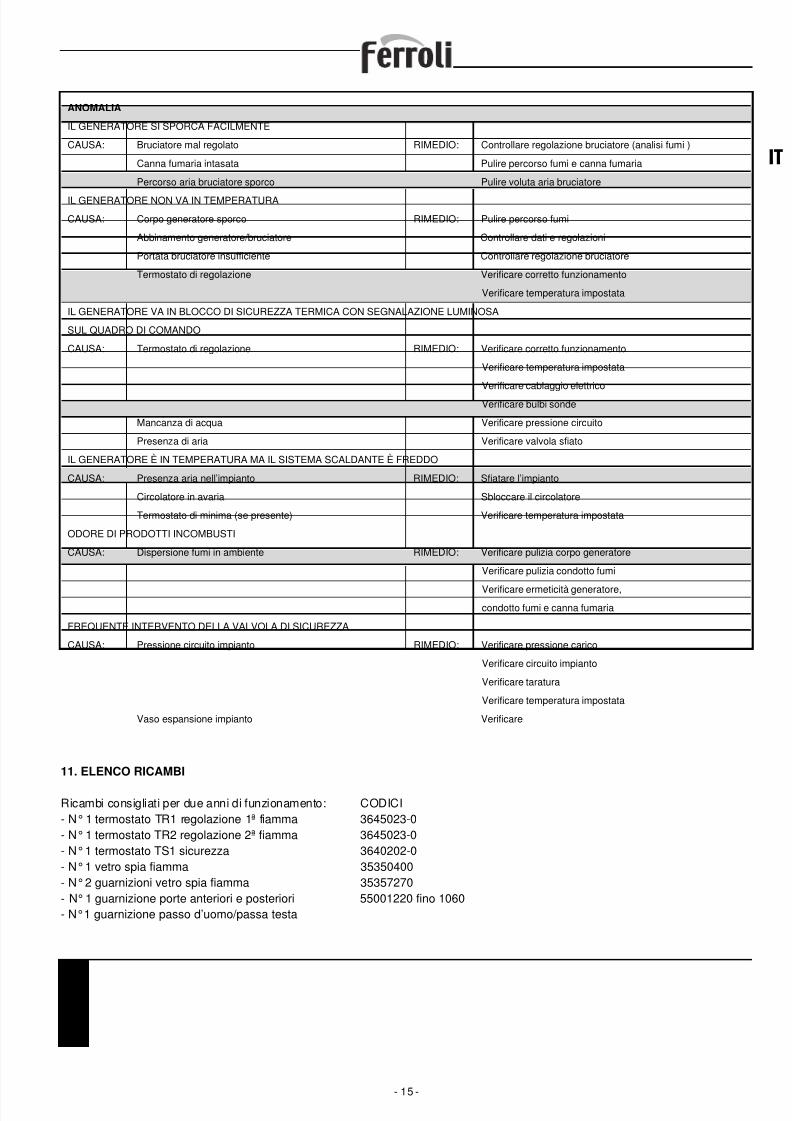
10.8 Possibili guasti e rimedi
Di seguito una lista con le indicazioni dei principali guasti od
anomalie che si possono verificare nella gestione della cal-daia, con specificate le possibili cause e i relativi rimedi.
- 14 -
8/13/2019 1657_prextherm t 3g It+Gb
http://slidepdf.com/reader/full/1657prextherm-t-3g-itgb 15/36
11. ELENCO RICAMBI
Ricambi consigliati per due anni di funzionamento: CODICI- N°1 termostato TR1 regolazione 1ª fiamma 3645023-0- N°1 termostato TR2 regolazione 2ª fiamma 3645023-0- N°1 termostato TS1 sicurezza 3640202-0- N°1 vetro spia fiamma 35350400- N°2 guarnizioni vetro spia fiamma 35357270- N°1 guarnizione porte anteriori e posteriori 55001220 fino 1060- N°1 guarnizione passo d’uomo/passa testa
- 15 -
IT
ANOMALIA
IL GENERATORE SI SPORCA FACILMENTE
CAUSA: Bruciatore mal regolato RIMEDIO: Controllare regolazione bruciatore (analisi fumi )
Canna fumaria intasata Pulire percorso fumi e canna fumaria
Percorso aria bruciatore sporco Pulire voluta aria bruciatore
IL GENERATORE NON VA IN TEMPERATURA
CAUSA: Corpo generatore sporco RIMEDIO: Pulire percorso fumi
Abbinamento generatore/bruciatore Controllare dati e regolazioni
Portata bruciatore insufficiente Controllare regolazione bruciatore
Termostato di regolazione Verificare corretto funzionamento
Verificare temperatura impostata
IL GENERATORE VA IN BLOCCO DI SICUREZZA TERMICA CON SEGNALAZIONE LUMINOSA
SUL QUADRO DI COMANDO
CAUSA: Termostato di regolazione RIMEDIO: Verificare corretto funzionamento
Verificare temperatura impostata
Verificare cablaggio elettrico
Verificare bulbi sonde
Mancanza di acqua Verificare pressione circuito
Presenza di aria Verificare valvola sfiato
IL GENERATORE È IN TEMPERATURA MA IL SISTEMA SCALDANTE È FREDDO
CAUSA: Presenza aria nell’impianto RIMEDIO: Sfiatare l’impianto
Circolatore in avaria Sbloccare il circolatore
Termostato di minima (se presente) Verificare temperatura impostata
ODORE DI PRODOTTI INCOMBUSTI
CAUSA: Dispersione fumi in ambiente RIMEDIO: Verificare pulizia corpo generatore
Verificare pulizia condotto fumi
Verificare ermeticità generatore,condotto fumi e canna fumaria
FREQUENTE INTERVENTO DELLA VALVOLA DI SICUREZZA
CAUSA: Pressione circuito impianto RIMEDIO: Verificare pressione carico
Verificare circuito impianto
Verificare taratura
Verificare temperatura impostata
Vaso espansione impianto Verificare
8/13/2019 1657_prextherm t 3g It+Gb
http://slidepdf.com/reader/full/1657prextherm-t-3g-itgb 16/36- 16 -
CONTENTS
1. Presentation . . . . . . . . . . . . . . . . . . . . . . . . . . . . . . . . . . . . . . . . . . . . . . . . . . . . . . . . . . . . . . . . . . . . . . . . . . . . . . . . . . page 172. General warnings . . . . . . . . . . . . . . . . . . . . . . . . . . . . . . . . . . . . . . . . . . . . . . . . . . . . . . . . . . . . . . . . . . . . . . . . . . . . . . page 173. Certification . . . . . . . . . . . . . . . . . . . . . . . . . . . . . . . . . . . . . . . . . . . . . . . . . . . . . . . . . . . . . . . . . . . . . . . . . . . . . . . . . . page 174. Technical and constructional specifications, dimensions . . . . . . . . . . . . . . . . . . . . . . . . . . . . . . . . . . . . . . . . . . . . . . . . page 17
4.1 Description of the appliance . . . . . . . . . . . . . . . . . . . . . . . . . . . . . . . . . . . . . . . . . . . . . . . . . . . . . . . . . . . . . . . . . . . page 174.2 Operating principle . . . . . . . . . . . . . . . . . . . . . . . . . . . . . . . . . . . . . . . . . . . . . . . . . . . . . . . . . . . . . . . . . . . . . . . . . . page 184.3 Technical specifications - Dimensions - Water fittings . . . . . . . . . . . . . . . . . . . . . . . . . . . . . . . . . . . . . . . . . . . . . . . page 184.4 Identification . . . . . . . . . . . . . . . . . . . . . . . . . . . . . . . . . . . . . . . . . . . . . . . . . . . . . . . . . . . . . . . . . . . . . . . . . . . . . . . page 19
5. Installation . . . . . . . . . . . . . . . . . . . . . . . . . . . . . . . . . . . . . . . . . . . . . . . . . . . . . . . . . . . . . . . . . . . . . . . . . . . . . . . . . . . . page 195.1 Packaging . . . . . . . . . . . . . . . . . . . . . . . . . . . . . . . . . . . . . . . . . . . . . . . . . . . . . . . . . . . . . . . . . . . . . . . . . . . . . . . . . page 195.2 Handling . . . . . . . . . . . . . . . . . . . . . . . . . . . . . . . . . . . . . . . . . . . . . . . . . . . . . . . . . . . . . . . . . . . . . . . . . . . . . . . . . . page 195.3 Boiler room . . . . . . . . . . . . . . . . . . . . . . . . . . . . . . . . . . . . . . . . . . . . . . . . . . . . . . . . . . . . . . . . . . . . . . . . . . . . . . . . page 195.4 Discharge of the products of combustion . . . . . . . . . . . . . . . . . . . . . . . . . . . . . . . . . . . . . . . . . . . . . . . . . . . . . . . . . page 195.5 Water connections . . . . . . . . . . . . . . . . . . . . . . . . . . . . . . . . . . . . . . . . . . . . . . . . . . . . . . . . . . . . . . . . . . . . . . . . . . page 19
5.5.1 Supply water . . . . . . . . . . . . . . . . . . . . . . . . . . . . . . . . . . . . . . . . . . . . . . . . . . . . . . . . . . . . . . . . . . . . . . . . . . page 195.5.2 Central heating outlet/return pipes . . . . . . . . . . . . . . . . . . . . . . . . . . . . . . . . . . . . . . . . . . . . . . . . . . . . . . . . . page 20
5.5.3 System fill/drain pipes . . . . . . . . . . . . . . . . . . . . . . . . . . . . . . . . . . . . . . . . . . . . . . . . . . . . . . . . . . . . . . . . . . page 205.5.4 Expansion vessel and safety valve pipes . . . . . . . . . . . . . . . . . . . . . . . . . . . . . . . . . . . . . . . . . . . . . . . . . . . . page 205.5.5 Recirculating pump . . . . . . . . . . . . . . . . . . . . . . . . . . . . . . . . . . . . . . . . . . . . . . . . . . . . . . . . . . . . . . . . . . . . . page 20
6. Boiler components . . . . . . . . . . . . . . . . . . . . . . . . . . . . . . . . . . . . . . . . . . . . . . . . . . . . . . . . . . . . . . . . . . . . . . . . . . . . . . page 206.1 Front door . . . . . . . . . . . . . . . . . . . . . . . . . . . . . . . . . . . . . . . . . . . . . . . . . . . . . . . . . . . . . . . . . . . . . . . . . . . . . . . . . page 206.2 Opening and adjusting the front doors . . . . . . . . . . . . . . . . . . . . . . . . . . . . . . . . . . . . . . . . . . . . . . . . . . . . . . . . . . . page 216.3 Opening and adjusting the rear doors . . . . . . . . . . . . . . . . . . . . . . . . . . . . . . . . . . . . . . . . . . . . . . . . . . . . . . . . . . . page 216.4 Furnace access manhole . . . . . . . . . . . . . . . . . . . . . . . . . . . . . . . . . . . . . . . . . . . . . . . . . . . . . . . . . . . . . . . . . . . . . page 216.5 Assembling the burner . . . . . . . . . . . . . . . . . . . . . . . . . . . . . . . . . . . . . . . . . . . . . . . . . . . . . . . . . . . . . . . . . . . . . . . page 216.6 Connecting the flame inspection window . . . . . . . . . . . . . . . . . . . . . . . . . . . . . . . . . . . . . . . . . . . . . . . . . . . . . . . . . page 21
7. Standard instrument panel . . . . . . . . . . . . . . . . . . . . . . . . . . . . . . . . . . . . . . . . . . . . . . . . . . . . . . . . . . . . . . . . . . . . . . . . page 227.1 Panel . . . . . . . . . . . . . . . . . . . . . . . . . . . . . . . . . . . . . . . . . . . . . . . . . . . . . . . . . . . . . . . . . . . . . . . . . . . . . . . . . . . . page 22
7.2 Panel front view . . . . . . . . . . . . . . . . . . . . . . . . . . . . . . . . . . . . . . . . . . . . . . . . . . . . . . . . . . . . . . . . . . . . . . . . . . . . page 227.3 Diagram of the terminal block electrical connections . . . . . . . . . . . . . . . . . . . . . . . . . . . . . . . . . . . . . . . . . . . . . . . . page 237.4 Wiring diagram for burner and single-phase pump . . . . . . . . . . . . . . . . . . . . . . . . . . . . . . . . . . . . . . . . . . . . . . . . . page 23
8. Principle diagram . . . . . . . . . . . . . . . . . . . . . . . . . . . . . . . . . . . . . . . . . . . . . . . . . . . . . . . . . . . . . . . . . . . . . . . . . . . . . . . page 249. Commissioning . . . . . . . . . . . . . . . . . . . . . . . . . . . . . . . . . . . . . . . . . . . . . . . . . . . . . . . . . . . . . . . . . . . . . . . . . . . . . . . . . page 25
9.1 Preliminary checks . . . . . . . . . . . . . . . . . . . . . . . . . . . . . . . . . . . . . . . . . . . . . . . . . . . . . . . . . . . . . . . . . . . . . . . . . . page 259.2 Starting for the first time . . . . . . . . . . . . . . . . . . . . . . . . . . . . . . . . . . . . . . . . . . . . . . . . . . . . . . . . . . . . . . . . . . . . . . page 25
9.3 Shutting down the boiler . . . . . . . . . . . . . . . . . . . . . . . . . . . . . . . . . . . . . . . . . . . . . . . . . . . . . . . . . . . . . . . . . . . . . . . . . . page 2510. Maintenance . . . . . . . . . . . . . . . . . . . . . . . . . . . . . . . . . . . . . . . . . . . . . . . . . . . . . . . . . . . . . . . . . . . . . . . . . . . . . . . . . . . page 25
10.1 General instructions . . . . . . . . . . . . . . . . . . . . . . . . . . . . . . . . . . . . . . . . . . . . . . . . . . . . . . . . . . . . . . . . . . . . . . . . . page 2510.2 Routine maintenance . . . . . . . . . . . . . . . . . . . . . . . . . . . . . . . . . . . . . . . . . . . . . . . . . . . . . . . . . . . . . . . . . . . . . . . . page 2510.3 Special maintenance . . . . . . . . . . . . . . . . . . . . . . . . . . . . . . . . . . . . . . . . . . . . . . . . . . . . . . . . . . . . . . . . . . . . . . . . page 2510.4 Alkaline wash or boiling . . . . . . . . . . . . . . . . . . . . . . . . . . . . . . . . . . . . . . . . . . . . . . . . . . . . . . . . . . . . . . . . . . . . . . page 26
10.5 Storing the generator when not in operation . . . . . . . . . . . . . . . . . . . . . . . . . . . . . . . . . . . . . . . . . . . . . . . . . . . . . . page 2610.6 Checking the operation of the boiler . . . . . . . . . . . . . . . . . . . . . . . . . . . . . . . . . . . . . . . . . . . . . . . . . . . . . . . . . . . . . page 2610.7 Checking the operation of the burner . . . . . . . . . . . . . . . . . . . . . . . . . . . . . . . . . . . . . . . . . . . . . . . . . . . . . . . . . . . . page 2610.8 Troubleshooting . . . . . . . . . . . . . . . . . . . . . . . . . . . . . . . . . . . . . . . . . . . . . . . . . . . . . . . . . . . . . . . . . . . . . . . . . . . . page 26
11. Spare parts list . . . . . . . . . . . . . . . . . . . . . . . . . . . . . . . . . . . . . . . . . . . . . . . . . . . . . . . . . . . . . . . . . . . . . . . . . . . . . . . . . page 27
8/13/2019 1657_prextherm t 3g It+Gb
http://slidepdf.com/reader/full/1657prextherm-t-3g-itgb 17/36- 17 -
GB
1. PRESENTATION
Dear Customer,Thank you for having chosen a PREXTHERM T 3G boiler.This manual has been prepared to provide you with informa-tion, warnings and suggestions on the installation, correct use
and maintenance of the boiler. Please therefore read it tho-roughly and keep it with care for future reference.
In your interest, we suggest that you carefully observe thecontents of this manual, so as to be able to get the mostfrom this high quality product.The Manufacturer declines all liability and the warranty will
be void in the event where the instructions described in thismanual are not observed.
2. GENERAL WARNINGS
- This instruction manual is an integral part of the product,and provides important instructions for installation, operationand maintenance.
- This appliance must only be used for the purposes it hasbeen specifically designed for.
- This appliance is used to heat water to below-boiling
temperatures at atmospheric pressure, and must be
connected to a central heating and/or domestic hot
water distribution system, according to its characteri-
stics, performance and heat output.
- Before installation, check that the boiler has not been dama-ged due to handling and transport.
- The boiler must be installed in compliance with the stan-dards in force, by suitably qualified personnel.
- Before performing any cleaning or maintenance operations,disconnect the appliance from the mains power supply.
- Ferroli S.p.A. is not liable for any damage to persons peopleand/or things due to errors in installation, control, mainte-nance and improper use.
- The boiler and the corresponding system must be commis-sioned by authorised personnel.
- Commissioning is performed in order to check the correctoperation of all the control devices.
- Qualified personnel must be contacted if the appliance is notused for an extended period.
- The installer must observe the local standards in force asregards: the choice of the site of installation of the boiler, the
compliance with the required ventilation conditions; the tight-ness of the connection to the chimney; the connections ofthe fuel lines, electrical systems and any other relevantsafety standards.
- Beware of any hot surface walls at the front and rear.- A differential water pressure switch that is activated when
there is no water MUST BE INSTALLED.
Warranty conditions
The warranty is only valid if the standards and the sugge-stions for use described in this manual are observed.Failure to observe such standards and suggestions will voidthe warranty. The warranty excludes all damage due to cor-rosion from the acidic condensate of the products of com-bustion or the formation of deposits caused by the use ofhard or aggressive water, as such are solely due to theoperation of the system.
Standards
The installer must observe the local standards in force asregards: the choice of the site of installation of the boiler,the compliance with the required ventilation conditions; the
tightness of the connection to the chimney; the connectionsof the fuel lines, electrical systems and any other relevantsafety standards.
3. CERTIFICATION
- CE mark, compliant with the directive that governs the useof pressurised appliances (97/23/EC) - Ts > 110°C.
- CE mark, compliant with the directive that governs the useof gased appliances (97/23/EC) - Ts > 110°C.
4. TECHNICAL AND CONSTRUCTIONAL
SPECIFICATIONS, DIMENSIONS
4.1 Description of the appliance
The significant aspects taken into consideration when desi-gning the PREXTHERM T 3G series boilers include thereduction of pollutants in the flue gas. An example of thesepollutants is nitrogen oxides (NOx), whose emissions areregulated in Europe by numerous standards and legislativerequirements. The procedures and welders are approved andcertified according to EN standards.The main technical elements of the design are:- the careful design of the shapes, to ensure an optimum ratio
between the combustion volumes and the heat exchange
surfaces.- The choice of materials used, for the long life of the boiler.The boilers feature pressurised combustion, three gas pas-ses, wet reversal chamber and are externally-fired. Thecombusted gas produced by the burner, after having left the
furnace and travelled through the combustion chamber,
enters the pipes in the second gas pass. When the flue gasreturns to the front part of the boiler, the direction is rever-sed again, travelling through the pipes in the third gas passand out towards the stack. This type of boiler ensures highaverage efficiency over the year, as well as a low content ofharmful substances in the flue gas. In addition, a furtheradvantage of the three gas pass structure is the reduction inthe time that the products of combustion remain in the hightemperature zone, consequently limiting the harmful nitro-gen oxide emissions. Another important factor in limiting theemission of nitrogen oxides is the volumetric heat load ofthe combustion chamber. It should be stressed that theemission of harmful substances in the flue gas also depends
significantly on the constructional solutions used for the bur-ners. The thermal insulation of the boiler body sees theapplication of a layer of mineral wool with a high insulationcapacity so as to reduce heat loss to extremely low levels;the finish is stainless steel plate. The maximum temperature
8/13/2019 1657_prextherm t 3g It+Gb
http://slidepdf.com/reader/full/1657prextherm-t-3g-itgb 18/36
difference allowed for the boiler (difference between theoutlet and return water temperature) is 30°C in all operatingconditions: otherwise ensure adequate solutions, for exam-ple, installing a recirculating pump. The hoisting hooks arelocated on the top of the plating. The boilers have four 1/2”fittings for probe bulb sheaths (suitable for housing 3 probe
bulbs each). The pre-wired control panel is located on theside of the boiler and ensures the automatic operation of theappliance. Maintenance and cleaning on the flue gas sideare simplified by suitably insulated hinged doors at the frontand rear, and a manhole at the rear to access the combu-stion chamber. Maintenance and inspection on the waterside is simplified by openings for the hand/head located onthe top body. Walk-on cover plate on the top of the boiler tosimplify assembly and maintenance.
4.2 Operating principle
The PREXTHERM T 3G are pressurised combustion boilers,
with three gas passes, externally-fired and with wet reversalchamber. The combusted gas produced by the burner, afterhaving left the furnace and travelled through the combustionchamber, enters the pipes in the second to gas pass. Whenthe flue gas returns to the front part of the boiler, the directionis reversed again, travelling through the pipes in the third gaspass and out towards the stack. During the operation of theburner, the combustion chamber is always under pressure.
For the pressure values see the table of technical specifica-tions, under the column Flue gas side pressure drop. The flueand the flue stack fitting must be made in compliance with thestandards and the legislation in force, using rigid pipes thatare resistant to high temperatures, condensate and mechani-cal stress, and are airtight (Fig. 1-2).
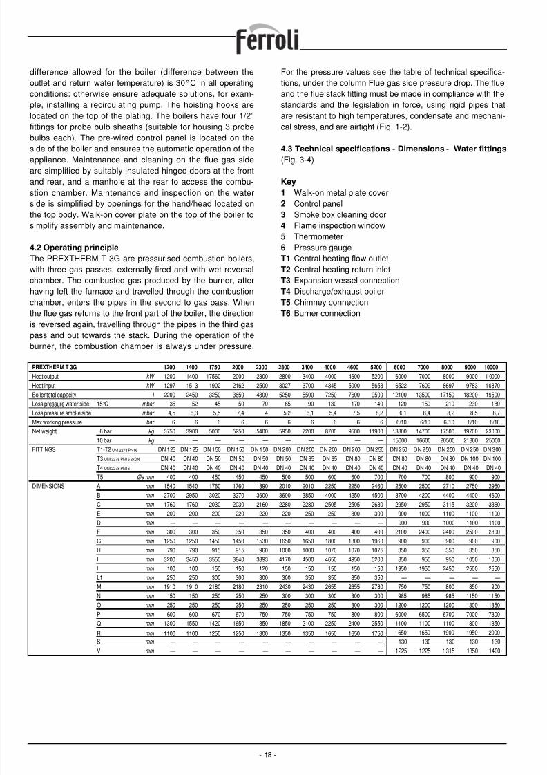
4.3 Technical specifications - Dimensions - Water fittings
(Fig. 3-4)
Key
1 Walk-on metal plate cover2 Control panel3 Smoke box cleaning door4 Flame inspection window5 Thermometer6 Pressure gaugeT1 Central heating flow outlet
T2 Central heating return inletT3 Expansion vessel connectionT4 Discharge/exhaust boilerT5 Chimney connectionT6 Burner connection
- 18 -
PREXTHERM T 3G 1200 1400 1750 2000 2300 2800 3400 4000 4600 5200 6000 7000 8000 9000 10000
Heat output kW 1200 1400 17560 2000 2300 2800 3400 4000 4600 5200 6000 7000 8000 9000 1 0000
Heat input kW 1297 1513 1902 2162 2500 3027 3700 4345 5000 5653 6522 7609 8697 9783 10870
Boiler total capacity l 2200 2450 3250 3650 4800 5250 5500 7250 7600 9500 12100 13500 17150 18200 19500
Loss pressure water side 15°C mbar
35 52 45 50 70 65 90 130 170 140 120 150 210 230 180Loss pressure smoke side mbar 4,5 6,3 5,5 7,4 4 5,2 6,1 5,4 7,5 8,2 6,1 8,4 8,2 8,5 8,7
Max working pressure bar 6 6 6 6 6 6 6 6 6 6 6/10 6/10 6/10 6/10 6/10
Net weight 6 bar kg 3750 3900 5000 5250 5400 5950 7200 8700 9500 11900 13800 14700 17500 19700 23000
10 bar kg — — — — — — — — — — 15000 16600 20500 21800 25000
FITTINGS T1-T2 UNI 2278 PN16 DN 125 DN 125 DN 150 DN 150 DN 150 DN 200 DN 200 DN 200 DN 200 DN 250 DN 250 DN 250 DN 250 DN 250 DN 300
T3 UNI 2278 PN16 2xDN DN 40 DN 40 DN 50 DN 50 DN 50 DN 50 DN 65 DN 65 DN 80 DN 80 DN 80 DN 80 DN 80 DN 100 DN 100
T4 UNI 2278 PN16 DN 40 DN 40 DN 40 DN 40 DN 40 DN 40 DN 40 DN 40 DN 40 DN 40 DN 40 DN 40 DN 40 DN 40 DN 40
T5 Øe mm 400 400 450 450 450 500 500 600 600 700 700 700 800 900 900
DIMENSIONS A mm 1540 1540 1760 1760 1890 2010 2010 2250 2250 2460 2500 2500 2710 2750 2950
B mm 2700 2950 3020 3270 3600 3600 3850 4000 4250 4500 3700 4200 4400 4400 4600
C mm 1760 1760 2030 2030 2160 2280 2280 2505 2505 2630 2950 2950 3115 3200 3360
E mm 200 200 200 220 220 220 250 250 300 300 900 1000 1100 1100 1100
D mm — — — — — — — — — — 900 900 1000 1100 1100
F mm 300 300 350 350 350 350 400 400 400 400 2100 2400 2400 2500 2800
G mm 1250 1250 1450 1450 1530 1650 1650 1800 1800 1960 900 900 900 900 900H mm 790 790 915 915 960 1000 1000 1070 1070 1075 350 350 350 350 350
I mm 3200 3450 3550 3840 3893 4170 4500 4650 4950 5200 850 950 950 1050 1050
L mm 100 100 150 150 120 150 150 150 150 150 1950 1950 2450 2500 2550
L1 mm 250 250 300 300 300 300 350 350 350 350 — — — — —
M mm 1910 1910 2180 2180 2310 2430 2430 2655 2655 2780 750 750 800 850 900
N mm 150 150 250 250 250 300 300 300 300 300 985 985 985 1150 1150
O mm 250 250 250 250 250 250 250 250 300 300 1200 1200 1200 1300 1350
P mm 600 600 670 670 750 750 750 750 800 800 6000 6500 6700 7000 7300
Q mm 1300 1550 1420 1650 1850 1850 2100 2250 2400 2550 1100 1100 1100 1300 1350
R mm 1100 1100 1250 1250 1300 1350 1350 1650 1650 1750 1650 1650 1900 1950 2000
S mm — — — — — — — — — — 130 130 130 130 130
V mm — — — — — — — — — — 1225 1225 1315 1350 1400
8/13/2019 1657_prextherm t 3g It+Gb
http://slidepdf.com/reader/full/1657prextherm-t-3g-itgb 19/36
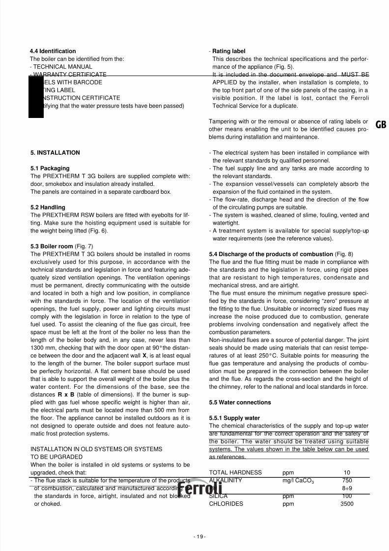
4.4 Identification
The boiler can be identified from the:- TECHNICAL MANUAL- WARRANTY CERTIFICATE- LABELS WITH BARCODE- RATING LABEL
- CONSTRUCTION CERTIFICATE(certifying that the water pressure tests have been passed)
- Rating label
This describes the technical specifications and the perfor-mance of the appliance (Fig. 5).It is included in the document envelope and MUST BEAPPLIED by the installer, when installation is complete, tothe top front part of one of the side panels of the casing, in a
visible position. If the label is lost, contact the FerroliTechnical Service for a duplicate.
Tampering with or the removal or absence of rating labels orother means enabling the unit to be identified causes pro-blems during installation and maintenance.
- 19 -
GB
5. INSTALLATION
5.1 Packaging
The PREXTHERM T 3G boilers are supplied complete with:door, smokebox and insulation already installed.
The panels are contained in a separate cardboard box.
5.2 Handling
The PREXTHERM RSW boilers are fitted with eyebolts for lif-ting. Make sure the hoisting equipment used is suitable forthe weight being lifted (Fig. 6).
5.3 Boiler room (Fig. 7)The PREXTHERM T 3G boilers should be installed in roomsexclusively used for this purpose, in accordance with thetechnical standards and legislation in force and featuring ade-quately sized ventilation openings. The ventilation openingsmust be permanent, directly communicating with the outsideand located in both a high and low position, in compliancewith the standards in force. The location of the ventilationopenings, the fuel supply, power and lighting circuits mustcomply with the legislation in force in relation to the type offuel used. To assist the cleaning of the flue gas circuit, freespace must be left at the front of the boiler no less than thelength of the boiler body and, in any case, never less than1300 mm, checking that with the door open at 90°the distan-ce between the door and the adjacent wall X, is at least equalto the length of the burner. The boiler support surface mustbe perfectly horizontal. A flat cement base should be usedthat is able to support the overall weight of the boiler plus the
water content. For the dimensions of the base, see thedistances R x B (table of dimensions). If the burner is sup-plied with gas fuel whose specific weight is higher than air,the electrical parts must be located more than 500 mm fromthe floor. The appliance cannot be installed outdoors as it isnot designed to operate outside and does not feature auto-matic frost protection systems.
INSTALLATION IN OLD SYSTEMS OR SYSTEMSTO BE UPGRADEDWhen the boiler is installed in old systems or systems to beupgraded, check that:
- The flue stack is suitable for the temperature of the productsof combustion, calculated and manufactured according tothe standards in force, airtight, insulated and not blockedor choked.
- The electrical system has been installed in compliance withthe relevant standards by qualified personnel.
- The fuel supply line and any tanks are made according tothe relevant standards.
- The expansion vessel/vessels can completely absorb the
expansion of the fluid contained in the system.- The flow-rate, discharge head and the direction of the flowof the circulating pumps are suitable.
- The system is washed, cleaned of slime, fouling, vented andwatertight.
- A treatment system is available for special supply/top-upwater requirements (see the reference values).
5.4 Discharge of the products of combustion (Fig. 8)The flue and the flue fitting must be made in compliance withthe standards and the legislation in force, using rigid pipesthat are resistant to high temperatures, condensate andmechanical stress, and are airtight.The flue must ensure the minimum negative pressure speci-fied by the standards in force, considering “zero” pressure atthe fitting to the flue. Unsuitable or incorrectly sized flues mayincrease the noise produced due to combustion, generateproblems involving condensation and negatively affect thecombustion parameters.Non-insulated flues are a source of potential danger. The jointseals should be made using materials that can resist tempe-ratures of at least 250°C. Suitable points for measuring theflue gas temperature and analysing the products of combu-stion must be prepared in the connection between the boilerand the flue. As regards the cross-section and the height of
the chimney, refer to the national and local standards in force.
5.5 Water connections
5.5.1 Supply water
The chemical characteristics of the supply and top-up waterare fundamental for the correct operation and the safety ofthe boiler. The water should be treated using suitablesystems. The values shown in the table below can be usedas references.
TOTAL HARDNESS ppm 10
ALKALINITY mg/l CaCO3 750PH 8÷9SILICA ppm 100CHLORIDES ppm 3500
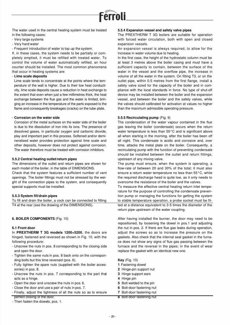
8/13/2019 1657_prextherm t 3g It+Gb
http://slidepdf.com/reader/full/1657prextherm-t-3g-itgb 20/36
The water used in the central heating system must be treatedin the following cases:- Very large systems- Very hard water- Frequent introduction of water to top up the system.If, in these cases, the system needs to be partially or com-
pletely emptied, it must be refilled with treated water. Tocontrol the volume of water automatically refilled, an hourcounter should be installed. The most common phenomenathat occur in heating systems are:- Lime scale deposits
Lime scale tends to concentrate at the points where the tem-perature of the wall is higher. Due to their low heat conducti-vity, lime scale deposits cause a reduction in heat exchange tothe extent that even when just a few millimetres thick, the heatexchange between the flue gas and the water is limited, brin-ging an increase in the temperature of the parts exposed to theflame and consequently breakages (cracks) on the tube plate.
- Corrosion on the water side
Corrosion of the metal surfaces on the water side of the boileris due to the dissolution of iron into its ions. The presence ofdissolved gases, in particular oxygen and carbonic dioxide,play and important part in this process. Softened and/or demi-neralised water provides protection against lime scale andother deposits, however does not protect against corrosion.The water therefore must be treated with corrosion inhibitors.
5.5.2 Central heating outlet/return pipes
The dimensions of the outlet and return pipes are shown foreach model of the boiler, in the table of DIMENSIONS.Check that the system features a sufficient number of ventopenings. The boiler fittings must not be stressed by the wei-ght of the connection pipes to the system, and consequentlyspecial supports must be installed.
5.5.3 System fill/drain pipes
To fill and drain the boiler, a cock can be connected to fittingT4 at the rear (see the drawing of the DIMENSIONS).
5.5.4 Expansion vessel and safety valve pipes
The PREXTHERM T 3G boilers are suitable for operationwith forced water circulation, both with open and closedexpansion vessels.An expansion vessel is always required, to allow for theincrease in water volume due to heating.
In the first case, the height of the hydrostatic column must beat least 3 metres above the boiler casing and must have asufficient capacity to contain, between the surface of thewater in the vessel and the overflow pipe, the increase involume of all the water in the system. On fitting T3, or on theoutlet pipe, within 0.5 metres from the first flange, install asafety valve sized for the capacity of the boiler and in com-pliance with the local standards in force. No type of shut-offdevice may be installed between the boiler and the expansionvessel, and between the boiler and the safety valves, whilethe valves should calibrated for activation at values no higherthan the maximum admissible operating pressure.
5.5.5 Recirculating pump (Fig. 9)The condensation of the water vapour contained in the fluegas leaving the boiler (condensate) occurs when the returnwater temperature is less than 55°C and is significant aboveall when starting in the morning, after the boiler has been offall night. This condensate is acidic and corrosive and, overtime, attacks the metal plate on the boiler. Consequently, arecirculating pump with the function of preventing condensateshould be installed between the outlet and return fittings,upstream of any mixing valve.The pump must ensure, when the system is operating, aflow-rate of between 20 and 30% of the total; it must alsoensure a return water temperature no less than 55°C, whilethe required discharge head is quite low, as it only needs toovercome the resistance of the boiler and the valves.To measure the effective central heating return inlet tempe-rature for the purpose of controlling the condensate preven-tion pump or managing the functions for getting the systemto stable temperature operation, a probe socket must be fit-ted at a distance equivalent to 3-5 times the diameter of thereturn pipe upstream of the water coupling.
- 20 -
6. BOILER COMPONENTS (Fig. 10)
6.1 Front doorIn PREXTHERM T 3G models 1200÷5200, the doors arehinged, fastened and reversed as shown in Fig. 10, with thefollowing procedure:- Unscrew the nuts in pos. 8 corresponding to the closing side
and open the door.- Tighten the same nuts in pos. 8 back onto on the correspon-
ding bolts but this time reversed (pos. 6).- Fully tighten the spare nuts (supplied with the boiler acces-
sories) in pos. 8.- Unscrew the nuts in pos. 7 corresponding to the part that
acts as a hinge.
- Open the door and unscrew the nuts in pos. 6.- Close the door and use a pair of nuts in pos. 7.- Finally, adjust the tightness of all the nuts so as to ensure
perfect closing of the door.- Then fasten the dowels, pos. 1.
After having installed the burner, the door may need to berepositioned, by loosening the dowel in pos.1 and adjusting
the nut in pos. 2. If there are flue gas leaks during operation,adjust the screws so as to increase the pressure on thegaskets. Also check that the internal seal gasket in the furna-ce does not show any signs of flue gas passing between thefurnace and the reversal in the pipes; in the event of wearreplace the gasket with an identical new one.
Key (Fig. 10)1 Fastening dowel2 Hinge-pin support nut3 Hinge support ears4 Hinge pin
5 Bolt welded to the pin6 Bolt-door fastening nut7 Bolt-door fastening nut8 Bolt-door fastening nut
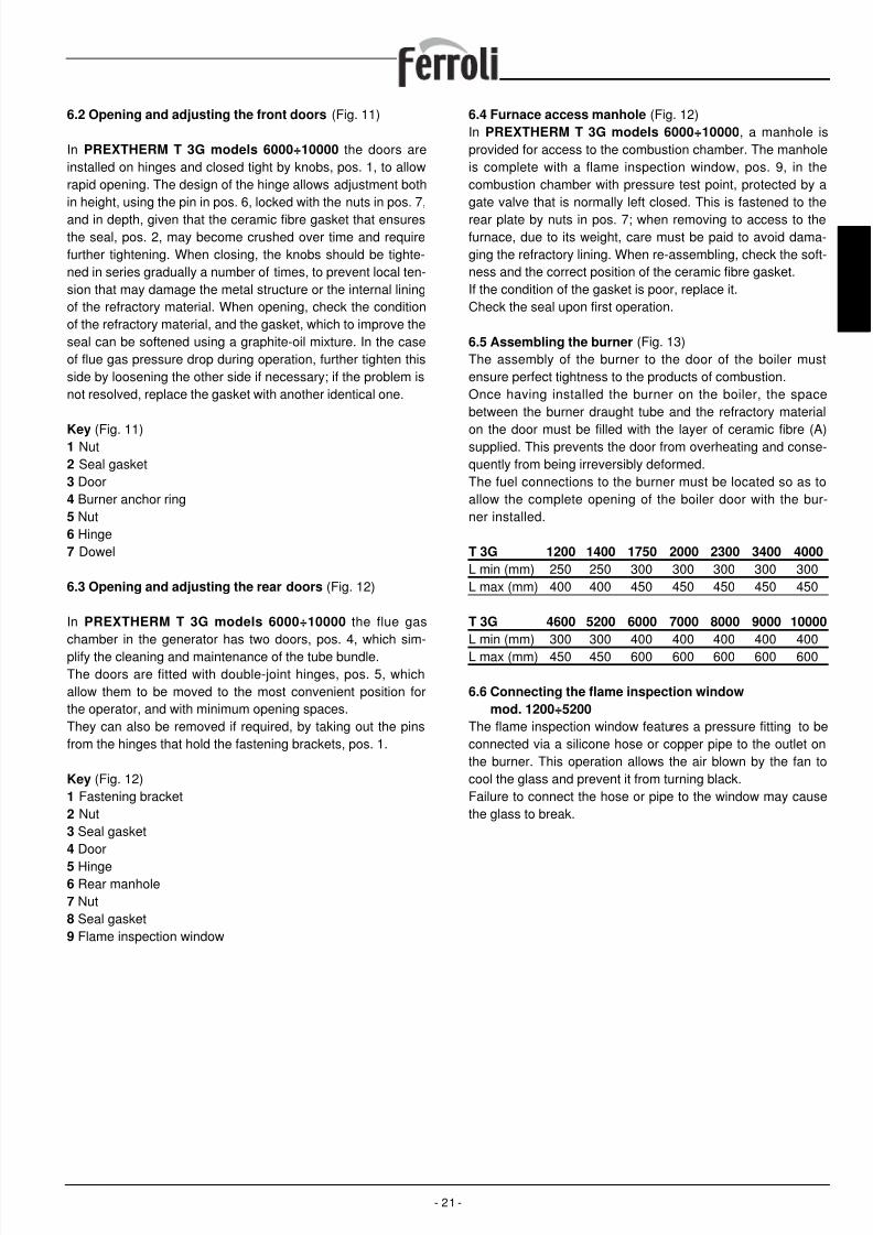
8/13/2019 1657_prextherm t 3g It+Gb
http://slidepdf.com/reader/full/1657prextherm-t-3g-itgb 21/36
6.2 Opening and adjusting the front doors (Fig. 11)
In PREXTHERM T 3G models 6000÷10000 the doors areinstalled on hinges and closed tight by knobs, pos. 1, to allowrapid opening. The design of the hinge allows adjustment bothin height, using the pin in pos. 6, locked with the nuts in pos. 7,
and in depth, given that the ceramic fibre gasket that ensuresthe seal, pos. 2, may become crushed over time and requirefurther tightening. When closing, the knobs should be tighte-ned in series gradually a number of times, to prevent local ten-sion that may damage the metal structure or the internal liningof the refractory material. When opening, check the conditionof the refractory material, and the gasket, which to improve theseal can be softened using a graphite-oil mixture. In the caseof flue gas pressure drop during operation, further tighten thisside by loosening the other side if necessary; if the problem isnot resolved, replace the gasket with another identical one.
Key (Fig. 11)1 Nut2 Seal gasket3 Door4 Burner anchor ring5 Nut6 Hinge7 Dowel
6.3 Opening and adjusting the rear doors (Fig. 12)
In PREXTHERM T 3G models 6000÷10000 the flue gaschamber in the generator has two doors, pos. 4, which sim-plify the cleaning and maintenance of the tube bundle.The doors are fitted with double-joint hinges, pos. 5, whichallow them to be moved to the most convenient position forthe operator, and with minimum opening spaces.They can also be removed if required, by taking out the pinsfrom the hinges that hold the fastening brackets, pos. 1.
Key (Fig. 12)1 Fastening bracket2 Nut3 Seal gasket4 Door
5 Hinge6 Rear manhole7 Nut8 Seal gasket9 Flame inspection window
6.4 Furnace access manhole (Fig. 12)In PREXTHERM T 3G models 6000÷10000, a manhole isprovided for access to the combustion chamber. The manholeis complete with a flame inspection window, pos. 9, in thecombustion chamber with pressure test point, protected by agate valve that is normally left closed. This is fastened to the
rear plate by nuts in pos. 7; when removing to access to thefurnace, due to its weight, care must be paid to avoid dama-ging the refractory lining. When re-assembling, check the soft-ness and the correct position of the ceramic fibre gasket.If the condition of the gasket is poor, replace it.Check the seal upon first operation.
6.5 Assembling the burner (Fig. 13)The assembly of the burner to the door of the boiler mustensure perfect tightness to the products of combustion.Once having installed the burner on the boiler, the spacebetween the burner draught tube and the refractory material
on the door must be filled with the layer of ceramic fibre (A)supplied. This prevents the door from overheating and conse-quently from being irreversibly deformed.The fuel connections to the burner must be located so as toallow the complete opening of the boiler door with the bur-ner installed.
T 3G 1200 1400 1750 2000 2300 3400 4000
L min (mm) 250 250 300 300 300 300 300L max (mm) 400 400 450 450 450 450 450
T 3G 4600 5200 6000 7000 8000 9000 10000
L min (mm) 300 300 400 400 400 400 400L max (mm) 450 450 600 600 600 600 600
6.6 Connecting the flame inspection window
mod. 1200÷5200
The flame inspection window features a pressure fitting to beconnected via a silicone hose or copper pipe to the outlet onthe burner. This operation allows the air blown by the fan tocool the glass and prevent it from turning black.Failure to connect the hose or pipe to the window may causethe glass to break.
- 21 -
GB
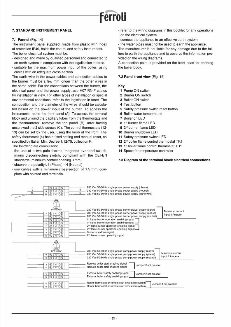
8/13/2019 1657_prextherm t 3g It+Gb
http://slidepdf.com/reader/full/1657prextherm-t-3g-itgb 22/36
7. STANDARD INSTRUMENT PANEL
7.1 Pannel (Fig. 14)The instrument panel supplied, made from plastic with indexof protection IP40, holds the control and safety instruments.The boiler electrical system must be:
- designed and made by qualified personnel and connected toan earth system in compliance with the legalisation in force.
- suitable for the maximum power input of the boiler, usingcables with an adequate cross-section.
The earth wire in the power cables and connection cables tothe burner must be a few mm longer than the other wires inthe same cable. For the connections between the burner, theelectrical panel and the power supply, use H07 RN-F cablesfor installation in view. For other types of installation or specialenvironmental conditions, refer to the legislation in force. Thecomposition and the diameter of the wires should be calcula-ted based on the power input of the burner. To access the
instruments, rotate the front panel (A). To access the terminalblock and unwind the capillary tubes from the thermostats andthe thermometer, remove the top panel (B), after havingunscrewed the 2 side screws (C). The control thermostats (12-13) can be set by the user, using the knob at the front. Thesafety thermostat (4) has a fixed setting and manual reset, asspecified by Italian Min. Decree 1/12/75, collection R.The following are compulsory:- the use of a two-pole thermal-magnetic overload switch,
mains disconnecting switch, compliant with the CEI-ENstandards (minimum contact opening 3 mm)
- observe the polarity L1 (Phase) - N (Neutral)- use cables with a minimum cross-section of 1.5 mm, com-
plete with pointed end terminals.
- refer to the wiring diagrams in this booklet for any operationson the electrical system.
- connect the appliance to an effective earth system.- the water pipes must not be used to earth the appliance.The manufacturer is not liable for any damage due to the fai-lure to earth the appliance and to observe the information pro-
vided on the wiring diagrams.A connection point is provided on the front head for earthingthe boiler body.
7.2 Panel front view (Fig. 15)
Key
1 Pump ON switch2 Burner ON switch3 Boiler ON switch4 Test button5 Safety pressure switch reset button
6 Boiler water temperature7 Boiler on LED8 1st burner flame LED9 2nd burner flame LED
10 Burner shutdown LED11 Safety pressure switch LED12 2nd boiler flame control thermostat TR113 1st boiler flame control thermostat TR114 Space for temperature controller
7.3 Diagram of the terminal block electrical connections
- 22 -
230 Vac 50-60Hz single-phase power supply (phase)230 Vac 50-60Hz single-phase power supply (neutral)230 Vac 50-60Hz single-phase power supply (earth wire)
230 Vac 50-60Hz single-phase burner power supply (earth)230 Vac 50-60Hz single-phase burner power supply (phase)230 Vac 50-60Hz single-phase burner power supply (neutral)1st flame burner operation enabling signal1st flame burner operation enabling signal2nd flame burner operation enabling signal
2nd flame burner operation enabling signalBurner shutdown signal2nd flame burner operating signal
Maximum currentinput 3 Ampere
230 Vac 50-60Hz single-phase pump power supply (earth)230 Vac 50-60Hz single-phase pump power supply (phase)230 Vac 50-60Hz single-phase pump power supply (neutral)
Maximum currentinput 3 Ampere
Remote boiler start enabling signalRemote boiler start enabling signal
Jumper if not present
External boiler safety enabling signalExternal boiler safety enabling signal
Jumper if not present
Room thermostat or remote start circulation system
Room thermostat or remote start circulation system
Jumper if not present
EARTH SCREW
EARTH SCREW
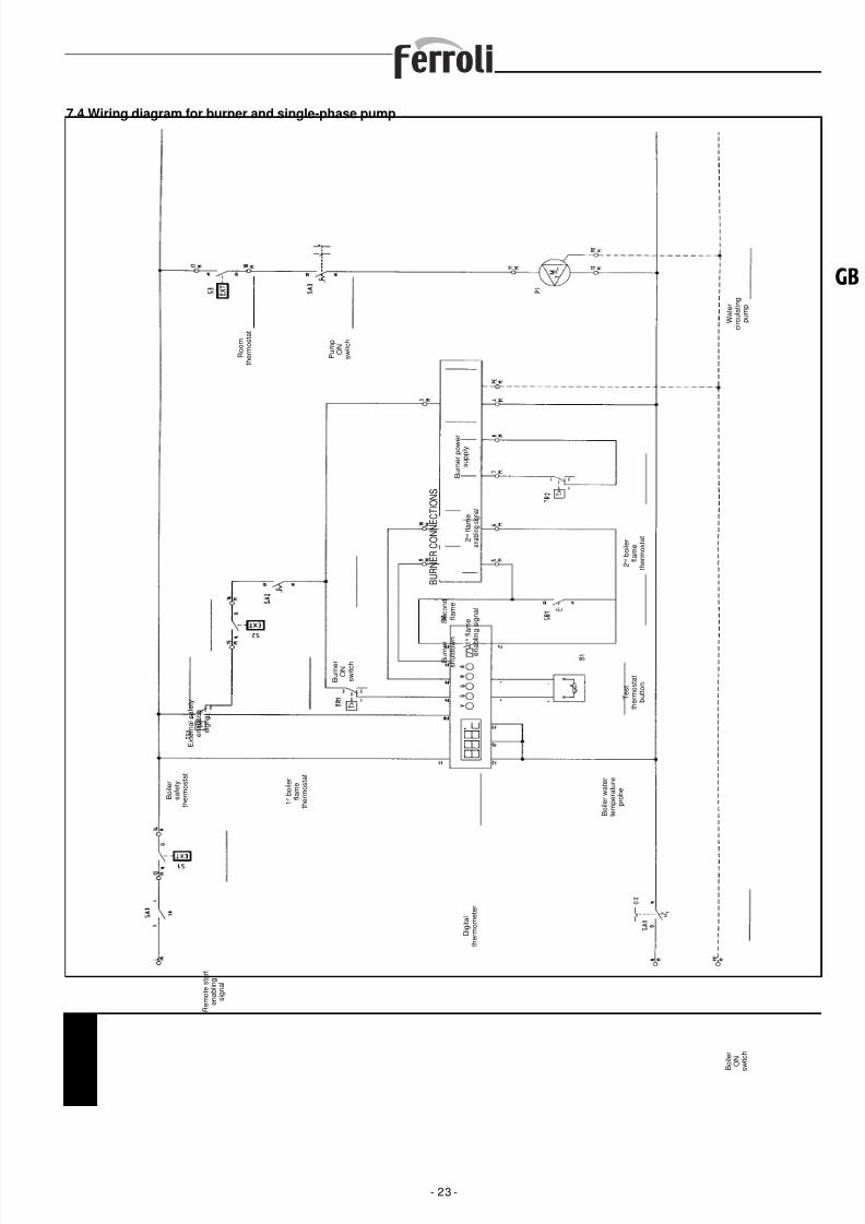
8/13/2019 1657_prextherm t 3g It+Gb
http://slidepdf.com/reader/full/1657prextherm-t-3g-itgb 23/36
7.4 Wiring diagram for burner and single-phase pump
- 23 -
GB
R e m o t e s t a r t
e n a b l i n g
s i g n a l
B o i l e r
s a f e t y
t h e r m o s t a t
E x t e r n a l s a f e t y
e n a b l i n g
s i g n a l
1 s t b o i l e r
f l a m e
t h e r m o s t a t
B u r n e r
O N
s w i t c h
B U R N E R
C O N N E C T I O N S
B u r n e r
s h u t d o w
n
S e c o n d
f l a m e
1
s t f l a m e
e n a b
l i n g s i g n a l
2 n d f l a m e
e n a b l i n g s i g n a l
B u r n e r p o w e r
s u p p l y
R o o m
t h e r m o s t a t
P u m p
O N
s w i t c h
W a t e r
c i r c u l a t i n g
p u m p
2 n d b o i l e r
f l a m e
t h e r m o s t a t
T e s t
t h e r m o s t a t
b u t t o n
B o i l e r w a t e r
t e m p e r a t u r e
p r o b e
B o i l e r
O N
s w i t c h
D i g i t a l
t h e r m o m e t e r

8/13/2019 1657_prextherm t 3g It+Gb
http://slidepdf.com/reader/full/1657prextherm-t-3g-itgb 24/36
Key to the symbols/components on the wiring diagram
- 24 -
COMPRESSED AIR
NITROGEN BOTTLES
SOFTENEDINDUSTRIAL WATER
EXPANSION TANK
CIRCULATING PUMPS
TO THE UTILITIES
BOILERCONTROL PANEL
CONDENSATE PREVENTION PUMP
COMBUSTION AIR
FROMTHE UTILITIES
3-WAY VALVE
GATE VALVE
DISK VALVE
BALL VALVE
BALL VALVE WITH RETURN SPRING
NON-RETURN VALVE
ON/OFF BALL VALVE WITH PNEUMATIC CONTROL
CHECK VALVE
THROTTLE VALVE
FLOW TOTALISER
SAFETY VALVE
“Y” FILTER
TEMPORARY FILTER
3-PIECE JOINT
FLEXIBLE PIPE
“FIGURE 8” DISK
RUBBER COMPENSATOR
CONDENSATE DISCHARGE
8. PRINCIPLE DIAGRAM (Fig. 16)The choice and installation of the components making upthe system is left to the expertise of the installer, whomust operate in a workmanlike manner and according tothe legislation in force.
The systems loaded with antifreeze require the use of waterdisconnecting devices. It should be stressed that the diagramin Fig. 16 is a principle diagram. In the case of differentsystems, please contact our After-Sales Service, which willprovide you all the details required.
Water outlet temperature
Boiler status/Water temperature instrument
System water pump
Remote start enabling signal
External safety enabling signal
Room thermostat
Boiler ON switch
Burner switch
Pump switch
Test button
1st burner stage thermostat
2nd burner stage thermostat
Boiler safety thermostat
NATURAL GASFROM MANIFOLD
8/13/2019 1657_prextherm t 3g It+Gb
http://slidepdf.com/reader/full/1657prextherm-t-3g-itgb 25/36
9. COMMISSIONING
9.1 Preliminary checks
Once having completed the water, electrical and fuel connec-tions to the boiler, before starting, check that:- The expansion vessel and the safety valve (if required) are
connected correctly and cannot be shut-off.- The bulbs of the thermostats and the thermometer are secu-
red inside the corresponding sheaths.- Check that all the control and safety devices are working
properly and correctly calibrated.- Check that the refractory linings have not been broken.- Check that the burner draught tube has been sealed correctly.- Check that the drain valves are closed and that the system
on/off valves are completely open.- The system is filled with water and completely vented of air.- The pump or the pumps are working properly.- The water, electrical, safety device and fuel connections
have been performed in compliance with the national andlocal legislation in force.- The burner is installed according to the instructions contai-
ned in the manual provided by the manufacturer.- The mains voltage and frequency are compatible with the
rating of the burner and the boiler’s electrical equipment.- The system is able to absorb the quantity of heat that will be
produced.- The recirculating pump is installed, as described in par. 5.5.5.
9.2 Starting for the first time
After the positive outcome of the checks described in the pre-vious paragraph, the burner can be ignited for the first time;this operation must be performed by a technician who has
been authorised by the Manufacturer of the burner.The technician has full responsibility as regards the field ofcalibration, within the declared and approved output range ofthe boiler. After having opened the fuel on-off cocks andchecked that there are no leaks in the supply line, place allthe switches on the ON position. The burner will thus beready for first ignition and for the adjustments to be made bythe authorised technician. On first ignition, check that thedoor, the burner flange and the connections to the chimneyare tight and that there is a slight negative pressure at thebase of the flue. The fuel rate must correspond to the boiler'srated data and under no circumstances must exceed the
maximum output value declared. The temperature of the fluegas must never fall below 160°C.
9.3 Shutting down the boiler
- Set the temperature controller to the minimum.- Disconnect power from the burner and close the fuel supply.- Let the pumps operate until they are stopped by the tempe-
rature controller.- Disconnect power from the electrical panel.
- 25 -
GB
10. MAINTENANCE
10.1 General instructions
Periodical maintenance is essential for the safety, efficiencyand long life of the appliance.All the operations must be carried out by qualified personnel.All cleaning and maintenance operations must be performedafter having closed the fuel supply and disconnected thepower supply. For the correct operation and maximum effi-ciency of the boiler, the combustion chamber, fire tubes andsmokebox must be cleaned regularly.
10.2 Routine maintenance
The interval between cleaning operations must be establishedby the user based on the experience acquired on each indivi-
dual system, consequently the maintenance intervals cannotbe established in advance.In any case, the following minimum intervals are recommen-ded, according to the fuel used:- Gas: once a year- Oil: twice a year- Fuel oil: every 300 hours of operationIn any case, any local maintenance standards in force shouldbe observed. During the routine maintenance operations,after having removed the turbulators, brush the tube bundleand the furnace. Remove the deposits accumulated in thesmokebox by opening the inspection doors.
For more intense cleaning, remove the rear smokebox and, ifdeteriorated, replace the flue gas seal. Check that the con-densate drain is not blocked. Ensure that the control andmeasurement devices serving the boiler are working correctly.
Measure the amount of top-up water added, and after havinganalysed the water, add descaler. The calcium and magne-sium salts dissolved in the water will, after repeated refills,cause deposits in the boiler and the overheating of the metalplate, with possible damage that is not attributable to mate-rials or workmanship, and consequently not covered by thewarranty. After having completed the maintenance and clea-ning operations and started the boiler again, check the tight-ness of the door and the smokebox, and in the event of gasleaks, replace the corresponding gaskets.The operations carried out must be entered in the system
logbook.
10.3 Special maintenance
Special maintenance to be performed at the end of the sea-
son or for extended shutdowns.All the operations described in the previous chapter must becompleted, plus the following additional operations:- Check the condition of the turbulators for wear.- After cleaning the flue gas circuit, wipe with a rag dipped in
a diluted solution of caustic soda. After having left to dry,wipe all the surfaces with a rag dipped in oil.
- Hygroscopic substances (quicklime, silica gel in small con-tainers) should be placed inside the furnace, which mustthen be closed hermetically so that air cannot enter.
- Do not empty the system and the boiler.- Protect the screws, nuts and pins on the door with graphite
grease.The operations carried out must be entered in the system
logbook.
8/13/2019 1657_prextherm t 3g It+Gb
http://slidepdf.com/reader/full/1657prextherm-t-3g-itgb 26/36
10.4 Alkaline wash or “boiling”
- This treatment is to be performed by specialist companieson the new boiler, so as to remove oxides and fatty and oilydeposits resulting from the production of the tubes and theassembly of the boiler and the system.
10.5 Storing the generator when not in operationA generator that works seasonally and then remains off forextended periods can be stored “dry” or “wet” when not used.- If the generator is exposed to harsh temperatures, it must be
stored “dry”, as follows:• Drain completely and clean the inside and outside, both on
the flue gas side and the water side.• Dry with compressed air.• Place containers of quicklime inside the cylindrical body,
so as to absorb any traces of humidity.Carefully close the on-off valves to prevent the penetrationof moisture from the air.
- To store the generator “wet”:• This involves completely filling the generator and addingpreservatives or neutralisers to the water. The systemshould then be sealed by closing all the on-off valves.This solution is not recommended if there is the risk of frost.
10.6 Checking the operation of the boiler
Before staring and running the functional tests on the boiler,make sure that:- The cocks in the water circuit and on the fuel lines are open.- Fuel is available.- The expansion vessel is suitably filled.- The pressure of the water circuit, when cold, is more than
1 bar and less than the maximum limit allowed for the boiler.- The water circuits have been vented.- The electrical connections to the mains power and the com-
ponents (burner, pump, control panel, thermostats etc.)have been completed.
- The phase-neutral connection must be observed, and theearth must be connected.
After having performed the operations described above, thefollowing operations are necessary to start the boiler:- If the system is fitted with a temperature controller or timer-
thermostat, check that these are “on”.
- Set the room timer-thermostat or the temperature controllerto the desired temperature.
- Move the main system switch to “on”- Set the boiler thermostat located on the control panel- Move the main switch on the control panel to “on” and check
that the green indicator light comes on.
The boiler will run the ignition phase and will remain on untilthe set temperature has been reached. If problems occurduring ignition or operation, the boiler will “LOCKOUT”, assignalled by the red light on the burner and the red indicatoron the control panel. After a “LOCKOUT”, wait around 30seconds before restoring the ignition conditions. To restorethe ignition conditions, press the burner “button/light” and waitfor the flame to ignite. If this operation fails, it can be repeateda maximum 2-3 times, then check:- The information provided in the burner instruction booklet.- The chapter on “CHECKING THE OPERATION OF THE
BOILER”.
- The electrical connections described on the diagramsupplied with the control panel.When the boiler has started, check that it stops and startsagain:- Adjust the setting of the boiler thermostat.- Move the main switch on the control panel.- Set the room thermostat, the timer or the temperature
controller.- Check that the pumps are not blocked and rotate in the
correct direction.- Check the total shutdown of the boiler using the main
system switch.If all the conditions are correct, restart the appliance, checkthe combustion (flue gas analysis), the fuel rate and the tight-ness of the gaskets on the door and the smokebox.
10.7 Checking the operation of the burner
- Refer to the burner instruction manual.- Follow all the local legislation in force on burner maintenance.
10.8 Troubleshooting
The following is a list with information on the main faults orproblems that may occur during the operation of the boiler,showing the possible causes and corresponding solutions.
- 26 -
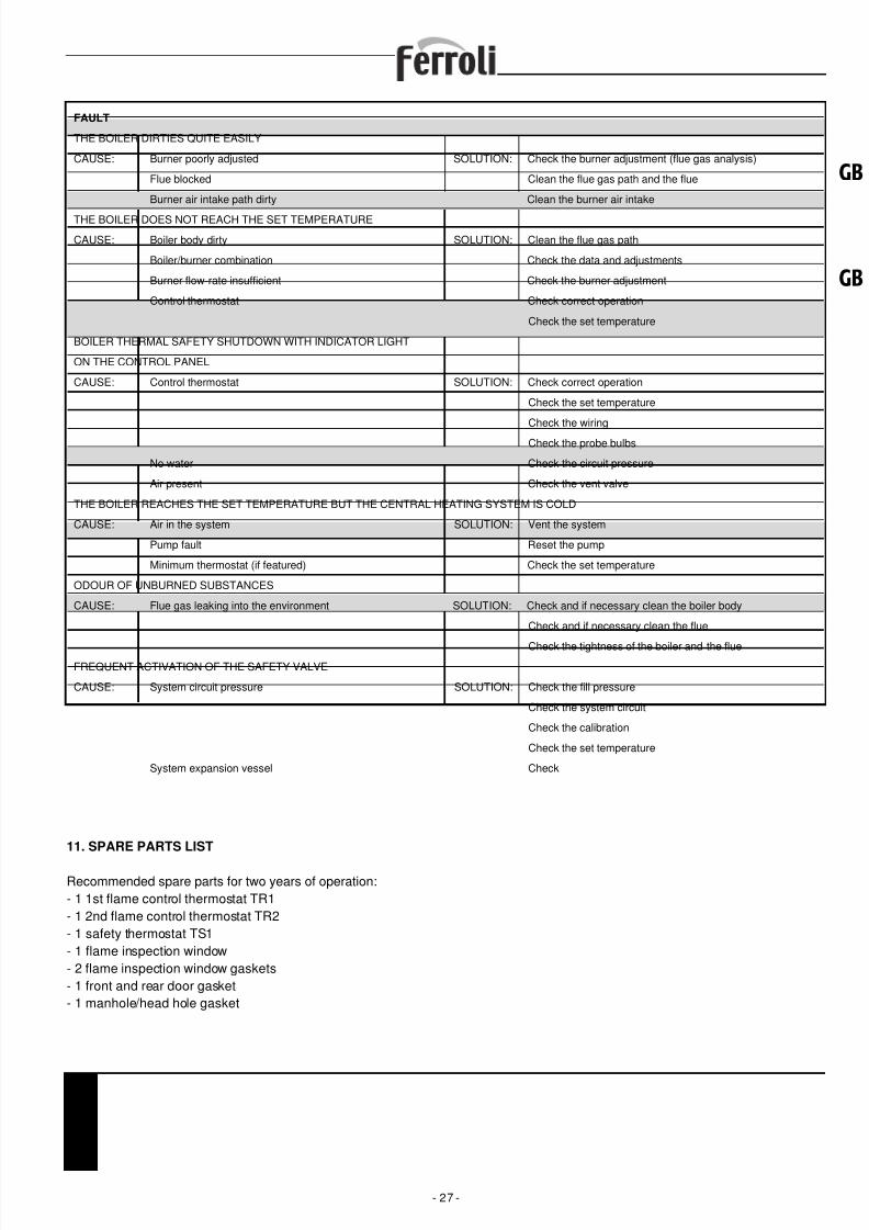
8/13/2019 1657_prextherm t 3g It+Gb
http://slidepdf.com/reader/full/1657prextherm-t-3g-itgb 27/36
11. SPARE PARTS LIST
Recommended spare parts for two years of operation:- 1 1st flame control thermostat TR1- 1 2nd flame control thermostat TR2- 1 safety thermostat TS1- 1 flame inspection window- 2 flame inspection window gaskets- 1 front and rear door gasket- 1 manhole/head hole gasket
- 27 -
GB
GB
FAULT
THE BOILER DIRTIES QUITE EASILY
CAUSE: Burner poorly adjusted SOLUTION: Check the burner adjustment (flue gas analysis)
Flue blocked Clean the flue gas path and the flue
Burner air intake path dirty Clean the burner air intake
THE BOILER DOES NOT REACH THE SET TEMPERATURE
CAUSE: Boiler body dirty SOLUTION: Clean the flue gas path
Boiler/burner combination Check the data and adjustments
Burner flow-rate insufficient Check the burner adjustment
Control thermostat Check correct operation
Check the set temperature
BOILER THERMAL SAFETY SHUTDOWN WITH INDICATOR LIGHT
ON THE CONTROL PANEL
CAUSE: Control thermostat SOLUTION: Check correct operation
Check the set temperature
Check the wiring
Check the probe bulbs
No water Check the circuit pressure
Air present Check the vent valve
THE BOILER REACHES THE SET TEMPERATURE BUT THE CENTRAL HEATING SYSTEM IS COLD
CAUSE: Air in the system SOLUTION: Vent the system
Pump fault Reset the pump
Minimum thermostat (if featured) Check the set temperature
ODOUR OF UNBURNED SUBSTANCES
CAUSE: Flue gas leaking into the environment SOLUTION: Check and if necessary clean the boiler body
Check and if necessary clean the flue
Check the tightness of the boiler and the flueFREQUENT ACTIVATION OF THE SAFETY VALVE
CAUSE: System circuit pressure SOLUTION: Check the fill pressure
Check the system circuit
Check the calibration
Check the set temperature
System expansion vessel Check
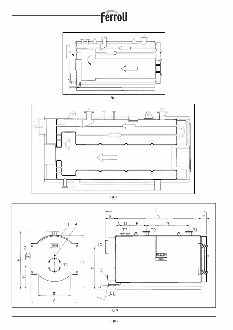
8/13/2019 1657_prextherm t 3g It+Gb
http://slidepdf.com/reader/full/1657prextherm-t-3g-itgb 28/36- 28 -
Fig. 1
Fig. 2
Fig. 3
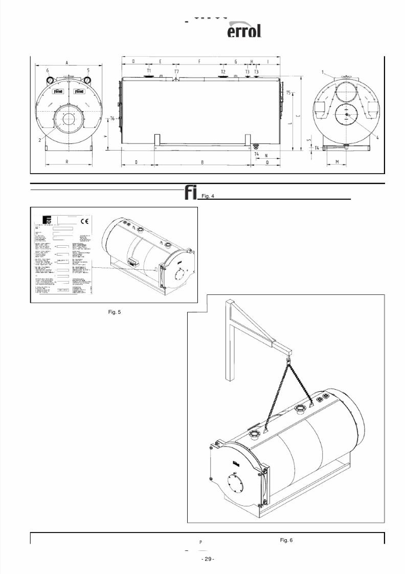
8/13/2019 1657_prextherm t 3g It+Gb
http://slidepdf.com/reader/full/1657prextherm-t-3g-itgb 29/36- 29 -
Fig. 4
Fig. 6
Fig. 5
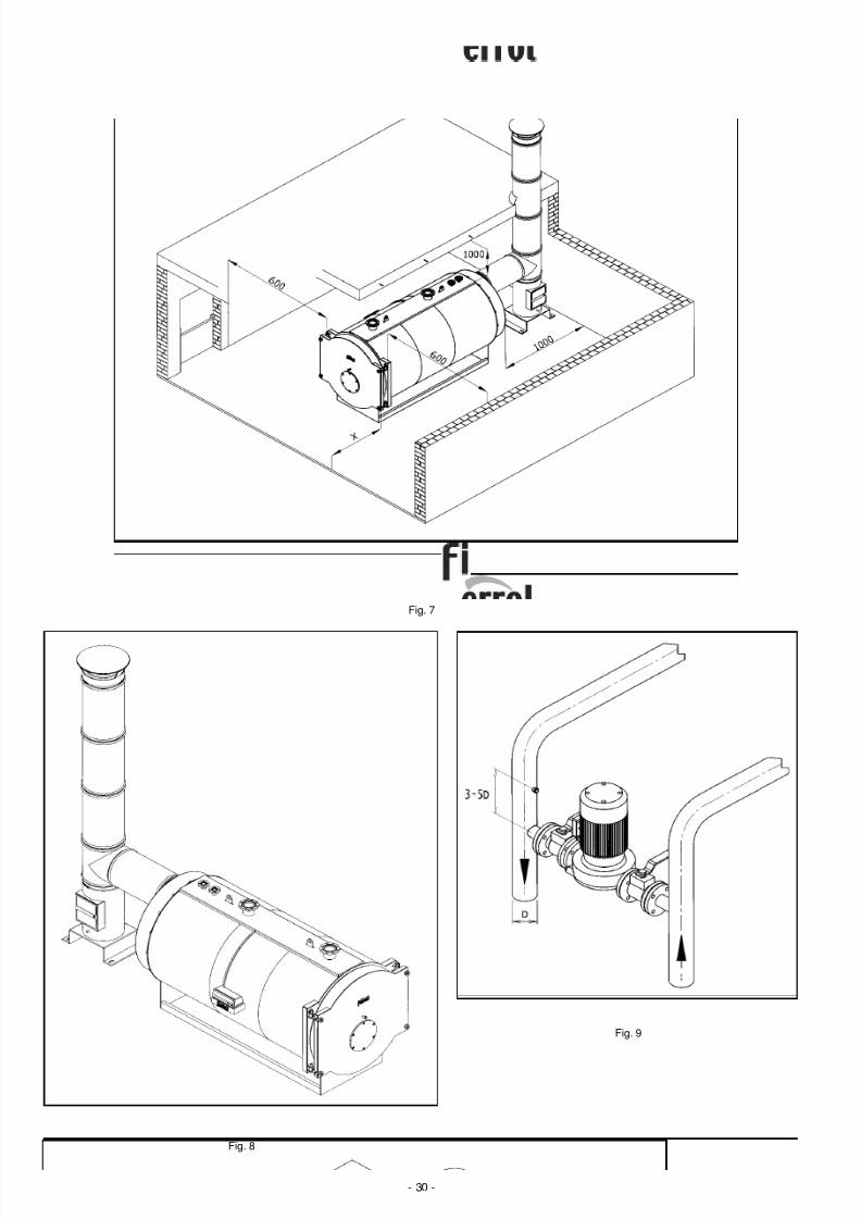
8/13/2019 1657_prextherm t 3g It+Gb
http://slidepdf.com/reader/full/1657prextherm-t-3g-itgb 30/36- 30 -
Fig. 7
Fig. 8
Fig. 9
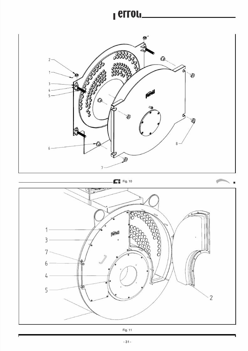
8/13/2019 1657_prextherm t 3g It+Gb
http://slidepdf.com/reader/full/1657prextherm-t-3g-itgb 31/36- 31 -
Fig. 10
Fig. 11
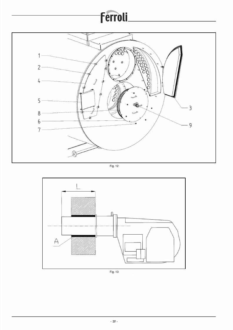
8/13/2019 1657_prextherm t 3g It+Gb
http://slidepdf.com/reader/full/1657prextherm-t-3g-itgb 32/36- 32 -
Fig. 12
Fig. 13
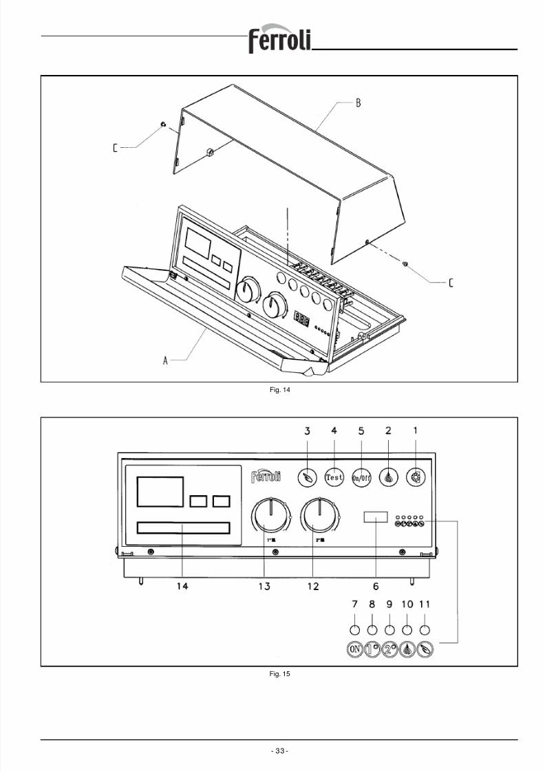
8/13/2019 1657_prextherm t 3g It+Gb
http://slidepdf.com/reader/full/1657prextherm-t-3g-itgb 33/36- 33 -
Fig. 14
Fig. 15

8/13/2019 1657_prextherm t 3g It+Gb
http://slidepdf.com/reader/full/1657prextherm-t-3g-itgb 34/36

8/13/2019 1657_prextherm t 3g It+Gb
http://slidepdf.com/reader/full/1657prextherm-t-3g-itgb 35/36

8/13/2019 1657_prextherm t 3g It+Gb
http://slidepdf.com/reader/full/1657prextherm-t-3g-itgb 36/36
FERROLI S.p.A.
via Ritonda 78/A ¬ 37047 San Bonifacio (VR) Italytel. +39 045 6139411 ¬ fax +39 045 6100933
www.ferroli.it