Embed Size (px)
Citation preview
PrAO-A1V3 169 ARMYUTANK-AUTOMOTIVE RESEARCH AND DEVELOPMENT COMMAND--ETC F/s 13/6
UNCLASSIFIED N
EEEEEEIE-EE-mmssmmmhEE.-EEEmIEhhEEsshhE-EEE
FY 1980A ( cANNUAL LABORATO RY 1
<HPO'STURE REPORT,o ACCOMPLISHMENTS I//
mt*PROGRAMS I
o MILESTONES
U.S. ARMY TANK-AUTOMOTIVERESEARCH AND DEVELOPMENT COMMAND
WARREN. MICHIGAN 48090
4,> 16XI
FOREWORD
The US Army Tank-Automotive Research and During FY8O, several coordination efforts were FY80 demonstrated considerable activity in theDevelopment Command (TARADCOM) can be strengthened: system development area. Significant ac-proud indeed of its last year (FY80) of (1) The Tank Science and Technology (S & 1) complishments included Army approval for theachievements. It was during this landmark year base was expanded to encompass all armored deployment of the High Mobility Multipurposethat TARADCOM received the award as Most combat vehicles. The Armored Combat Vehicle S Wheeled Vehicle to replace the aging M151Improved Laboratory, U. S. Army. & T program monitors and coordinates more %-ton truck and the Heavy Expanded Mobility
than 2,000 research projects related to armored Tactical Truck to fill the much needed 10-tonMany of the management initiatives of FY78 and vehicles at over a half-dozen commands. capacity resupply and refuel missions.FY79 bore fruit, and the award for the Most Im- (2) In the tactical vehicle area, a Tacticalproved Laboratory, which was presented to Wheeled Vehicle Management Office was formed Other activities included (1) type classifying theTACOM by Dr. P. A. Pierre, Assistant Secretary of which serves as the DARCOM focal point with M939 5-ton truck (2) initiating fielding of thethe Army, RD&A, became a reality. Competition TRADOC and DA for resolving the many M901 Improved TOW Vehicle, the M97for the award was between all Army Research bureaucratic log jams which in the past have 5000-gallon tanker, and the M871 22%-tonand Development Commands and laboratory blocked any motion toward resolving aging fleet breakbulk container semitrailer, (3) designing,organizations. problems. fabricating and delivery of 10 ARMVAL high
(3) Designation of TARADCOM as the lead mobility test vehicles for the Marine Corps, fourAs a continuation of the TARADCOM Laboratory laboratory for devising a program for meeting XM999 semitrailers for the Ground Launchedimprovement effort in FY80, TACOM's technical DOD and DA goals in the field of mobility energy Cruise Missile, and two XM974 semitrailers forprograms can be divided into three parts beginn- efficiency was established. This program, which the Patriot Air Defense System; and (4) begin-ing in FY81. will require extensive interface with MERADCOM ning of a compressed 33-month development(1) System projections involving the coordins- and AVRADCOM, encompasses all Army vehicles, program for the Fire Support Team Vehicle (FIST.
tion of TRADOC and various DARCOM major aircraft, and ground power units. V) and issuance of a request for proposal for thesubordinate commands in forecasting the need (4) Recognizing that the XMI tank and the M2 Field Artillery Ammunition Support Vehiclefor new, conceptual systems and necessary im- and M3 fighting vehicle system are now moving (FAASV).provements to existing equipment. to production, comprehensive planning for the(2) System development demonstrating con- 1990's for the next generation combat vehicle The continuing TARADCOM program and im-
cept technologies through the use of test beds or systems also was initiated. provement effort has resulted in a Tank-prototypes. Automotive R & D Community which is a more(3) Supporting technology programs consisting These coordination programs are particularly viable and demonstrably significant DARCOM
of the detail subsystem and component develop- significant as points of application for the resource than at any other time during its longment project aimed at providing the supporting technology under development within DARCOM history.laments required by target systems to meet for the Rapid Deployment Force and main battle
forecasted needs. tank and infantry fighting vehicle follow-ons.
A P . o n o r M . M ATTHEW S, JR.
Brigadier General, USADeputy Commanding General
Li., for Research and Development
command executive staff
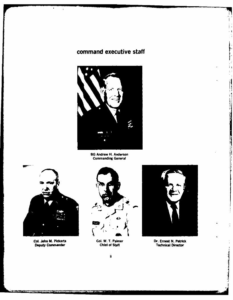
BG Andrew H. AndersonCommanding General
Col. John M. Pickarts Col. W. T. Palmer Dr. Ernest N. PetrickDeputy Commander Chief of Staff Technical Director
command executive stafff
Col. H. H. Dobbs LTC. T. H. Huber M. V. TooleyDirector, Tank-Automotive Acting Director, Tank-Automotive Comptrollerb
Systems Laboratory Concepts Laboratory
Col. James A. Chernault LTC. James G. WelshProfact Manager Product Manager, Armored Combat
Improved TOW Vehicle Vehicle Technology
George N~ewcomb Doga .Munro Lowell arnetDirector, Engineering Director, Initial Director, ProductSupport Directorate Acqluisftion Directorate Assurance Directorate
Robert Swint Joseph MouseChief, Integrated Chief, Systems and
Logistics Support Office Cost Analysis Office
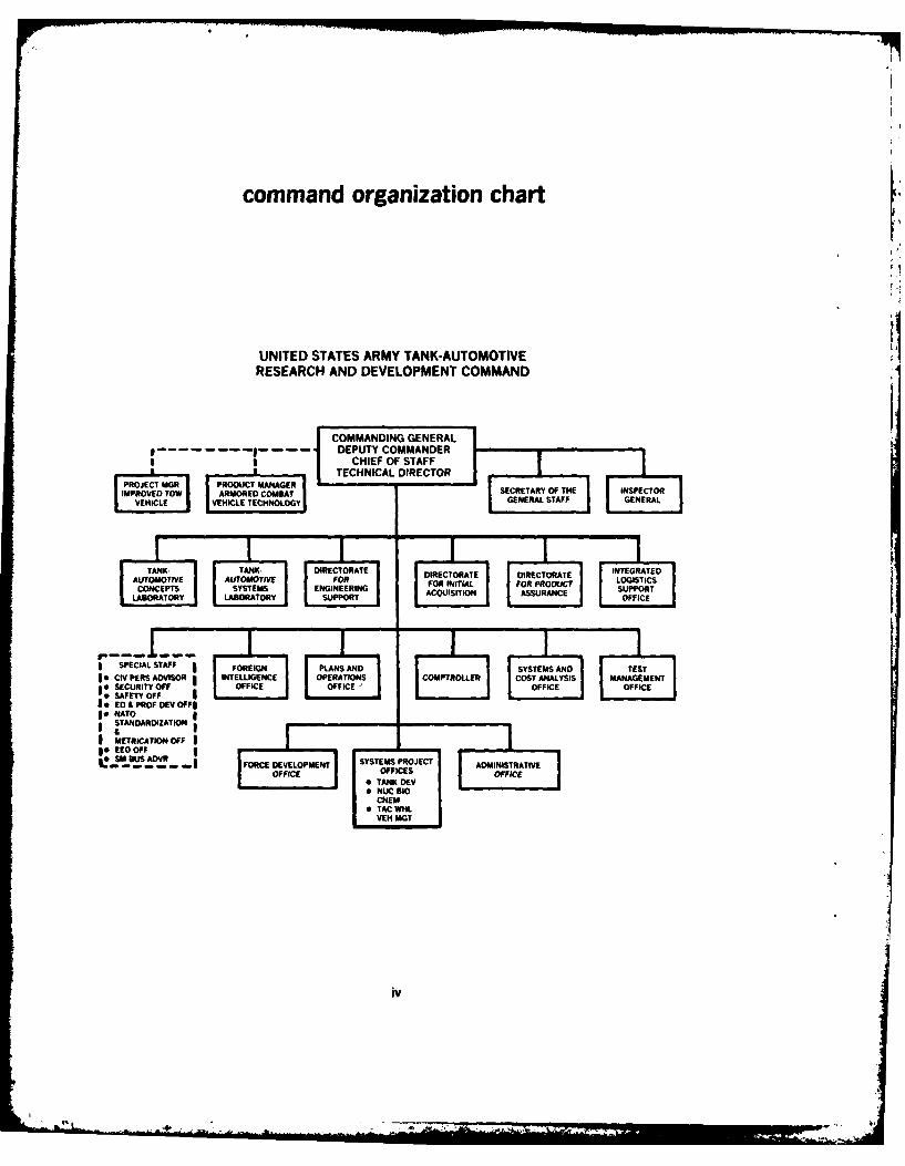
command organization chart
UNITED STATES ARMY TANK-AUTOMOTIVERESEARCH AND DEVELOPMENT COMMAND
---- - DEPUTY COMMANDERII I CHIEF OF STAFF• |TECHNICAL DIRECTOR rPEO OT SECRETARY OF THE INSPECTOR
V E HECHNOGY GENERAL STAFF GENERAL
TANK-AT DIRECORATRECTECTOATE INTERAEDAUTOMOTIVEVE FOR IITIAL FOR PRODUCT LOGISTICSCONCE YSTEMS E RING ASSURANCE SUPPORT
IABORATSATORY AS OFFICE
* SPECIAL STAFF FOREIGN PLANS A ND SYSTES AND TEST
SECURITY OFF OFFICE OFFICE OFFICE OFFICE;: SAFETY OFFED & PROF DEV OFF$
le NATODTANDARDIZATION
I METRICATION OFFso EEO OFF
FORCE DEVELOPMENT SYSTEMS PROJECT ADMINISTRATIVEOFF OFFICES OFFICE•TANK DiEV
NUC IDCHEM l
* TAC WIlLVEH MGT
iv
L.
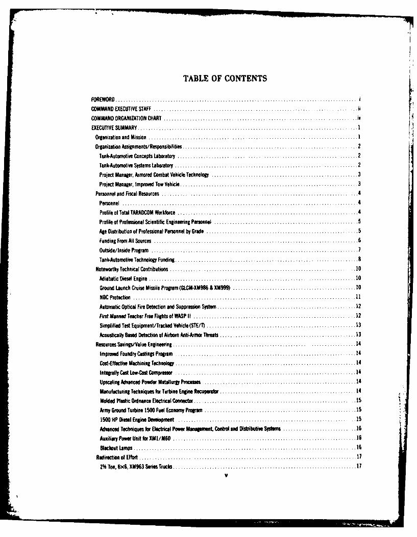
TABLE OF CONTENTS
FOREW ORD .. .. . . .. . . .. . .. . . .. . .. . . .. . . . .. . .. . .. . . . .. . . . . .
COMMAND EXECUTIVE STAFF......................... ...................................... ii
COMMAND ORGANIZATION CHART ............................................... ............. ivEXECUTIVE SUMMARY....................-............................................1
Organization and Mission.. .................................................................. 1IOrganization Assignments/Responsibilities ....................................................... 2
Tank-Automotive Concepts Laboratory .......................................................... 2
Tank-Automotive Systems Laboratory .......................................................... 2Project Manager, Armored Combat Vehicle Technology .............................................. 3Project Manager, Improved Tow Vehicle..........................................................3
Personnel and Fiscal Resources ........................... ................................. 4
Personnel .. .. . .. . . .. . . .. . . .. . . .. . . .. . .. . . .. . . .. . . .. . .. .4Profile of Total TARAOCOM Workforce ........................................................ 4
Profile of Professional Scientific Engineering Personnel .............................................. 5Age Distribution of Professional Personnel by Grade................................................ SFunding From All Sources.................................................................. 6
Outside/ Inside Program ................................................................... 7Tank-Automotive Technology Funding..........................................................8
Noteworthy Technical Contributions ....................................................--..... 10Adiabatic Diesel Engine . .. . . .. . .. . . . .. . .. . . .. . . .. . . . . . . .. . .. . ..10
Ground Launch Cruise Missile Program (GLCM-XM986 & XM999)....................................... 10NBC Protection .. . . . .. . . .. . .. . .. .. . . .. . . .. . . ... .. . . .. . . .. . . 1Automatic Optical Fire Detection and Suppression System ............................................ 12First Manned Teacher Free Flights of WASP 11.......I......................................... ... 12Simplified Test Equipment/Tracked Vehicle (STE/i) ............................................... 13Acoustically Based Detection of Airborn Anti-Armor Threats........................................... 13
Resources Savings/Value Engineering......................... ............... ................. 14
Improved Foundry Castings Program ..... .................................................... 14
Cost-Effective Machining Technology ......................................................... 14Integrally Cast Low-Cast Compresso........................................................ 14
Upscaling Advanced Powder Metallurgy P icesses .......... _.............................. ....... 14
Manufactur ing Techniques for Turbine Engine Recuperator .......................................... 14Molded Plastic Ordnance Electrical Connector .............................. ................... 15Army Ground Turbine 1500 Fuel Economy Program................................... ............ 151500 lHP Diesel Engine Development .. . .. . .. . . .. . . . . .. . . . .. . . .. . . .. . . ..15
Advanced Techniques for Electrical Power Mainagement. Control and Distrbutive Systm....................... 16Auxiliary Power Unit for XMI/M60 .. . . . .. . .. . . .. . . .. . . .. . .. . . .. . . .. . ..16Blackout Lamps............................................. ....................... .16
Redirection of Effort .................................................................... 172%, Ton, 6x6i, XM963 Series Trucks .......................................................... 17
V
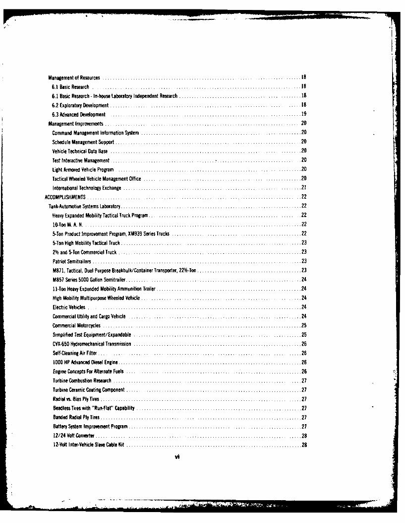
Management of Resources ................ ............................. ...... .......... 18
6.1 Basic Research . ................................................... 18 I
6.1 Basic Research - In-house Laboratory Independent Research ................. .... .. 186.2 Exploratory Development....................................... ................. ... 18
6.3 Advanced Development..................................................... ...... ... 19*Management Improvements................................................................. 20
Command Management Information System.....................................................20Schedule Management Supt............................................................ 20
Vehicle Technical Data Base........................................ ....................... 20Test Interactive Management ..................... ............................. 20
Light Armored Vehicle Program ... ............................................. 20
Tactical Wheeled Vehicle Management Office .... .............................................. 20
International Technology Exchange ..... ......................................... 21
ACCOMPLISHMENTS ..... ........................ ............................. 22
Tank-Automotive Systems Laboratory ........................................................... 22Heavy Expanded Mobility Tactical Truck Program.................................................. 22
10-Ton M .A .N .. .. . .. . . . .. . .. . . .. . . .. . . .. . . .. . .. . . .. . . .. . .225-Ton Product Improvement Program, XM939 Series Trucks...........................................225-Ton High Mobility Tactical Truck ........................................................... 232% and 5-Ton Commercial Truck...................... .................................. 23Patriot Semitrailers ................................................... ......... ........ 23M87 1, Tactical, Dual Purpose Breakbul k/ Container Transporter, 22 -Ton .................................. 23M857 Series 5000 Gallon Semitrailer.......................................................... 2411I-Ton Heavy Expanded Mobility Ammunition Trailer ............................................... 24High Mobility Multipurpose Wheeled Vehicle .... ............................................... 24Electric Vehicles ,.... .................................................................. 24
Commercial Utility and Cargo Vehicle ......................................................... 24Commercial Motorcycles.................................................................. 25Simplified Test Equipment/ Expandable ..................................................... 25CVX-650 Hydromechanical Transmission...................................................... 26Self-Cleaning Air Filter .............. ..... .............................................. 261000 HP Advanced Diesel Engine ..... ...................................................... 26Engine Concepts For Alternate Fuels ................................... ....... I............ 26Turbine Combustion Research ....... ............... .......................... 27
Turbine Ceramic Coating Component...........................................................27Radial vs. Bias Ply Tires ................................................... 27
Bead less Tires with "Run-Flat" Capability....................................................... 27Banded Radial Ply Tires........................................................ .......... 27Batery System Improvement Program ........................................................ 2712124 Volt Converter.... ................................................................. 2812-Volt Inter-Vehicle Slave Cable Kit...........................................................28
Single Leme Light Switch ... . . . .. . . .. . .. . . .. . . .. . .. . . .. . . .. . . .. ..28
Rotational Molded Polyethylene Fuel Tanks ..................................................... 28
VeehicleNois e Rduc tion......................................................... 28
Rise Power Train PIP: M113AIE1 Vehicle Development ............................................. 29Small Unit Support Vehicle ..................................... ......................... 29Advanced Antiarmor Vehicle Evaluation........................................................ 29Field Artillery Ammunition Support Vehicle ..................................................... 30M551 Mid-Life Product Improvement Progrm ......................... .........................30Remote Control Target Vehicle ................................................ ............ 30Manned Evasive Target Tank......................................................... . . .. .31FMS Technical Support Activity................................... ......................... 31Fire Control Systems Integration..............................................................31Army Fire Control Planning Guide Support....................................................... 31Turret and Weapon System Integration..........................................................31Automatic Tracker Evaluation .............................................................. 32Gun Bending Analysis.................................... .............................. 32Fire Survivability System Integration ................................. ...................... 32Passive Fire Protection for Hydraulic and Fuel Lines................................................ 32Gas-Liquid Dynamics .................................................................... 32Human Factors Evaluation -Armored Combat Vehicle Technology........................................33XT152 45-65 Ton Vehicle Track .............................................................. 33Track for 15-18 Ton Vehicles (XT- 150).......................................................... 33Track Bushing Test Machine ............................................ .................. 33Road Wheel Tire Bonding ............................................................. ....33Track Retention and Control ................................................................ 33Military Elastomers ..................................................... 34
Bi-Directional Suspension System ............................................................ 34Adaptive Suspension .................................................................... 34Vehicle Hardening (Track and Suspension)....................................................... 35Independent External Suspension ............................................................ 35Fluidic Damper ........................................................................ 35Loopwheel Suspension.......................... ....................................... 36Laser Heat Treating of Track Components........................................................ 36Dissimilar Metals 19ining....... ........................................................ 36Flexible Machining Systems Vehicle Components.................................................. 36Threaded Fasteners - Locking Adhesive and Sealants................................................37Torsion Bar Development .. .. . . .. . . .. . .. . . .. . . .. . . .. . .. .. . . .. . . ..37Lawe Welding Techniques for Military Vehicles ................................................... 37Gear Die Design and Manufacturing .......................................................... 37Electrodes for Welding Steel Armor............................................................38
VII
Cast Arm or Repair . ...... .... .. ........ ... .... .. ...... ..... ... .... ... ...... ...... ...... ...... ...... 38
Im proved Large Arm or Steel Castings ..................................................................... 38Fabrication of Flat Thin-Gage Alloy Steel Plate .................... .............. . ....................... 38
Lightweight Armor Materials for High Explosive Fragmentation Protection ........................................ 38
Supplemental Armor Engineering Support -XM 1 ................. ...................................... ... 38Armor Protection from Overhead Threats ........................................................... ...... 38
Composite Armor ..... . .......................... 38
Spall Protection ................................................................................... . 38
Design Methods for Ballistic Shock ..... . .............................. .................. 39
NATO Protection /Vulnerability Model Standardization ...................................................... 39
Molded Plastic Ordnance Electrical Connector ......... ..................................................... 39
High-Strength M aterials and Com ponents ................................................................. 39
XM 975 Roland Carrier .. ................. .... ....................................................... 40
Tank-Automotive Concepts Laboratory .... ............... ............................................. .... 41
Survivability Optim ization M odel .............. ...... . ................................................. 41
Armored Combat Vehicle Technology Program Support ............................................... ...... 41
Armored Combat Vehicle Science and Technology Base Program ........................... . ............. 41
XM1 Product Improvement Planning ............................................... 42
Elevated Kinetic Energy Weapon Program ....................................................... . ..... 42
Acoustic Signature Reduction ...................................................................... . . 42
Joint Air Force - Army Countermeasure Evaluation Program .................................................... 43
Enhanced Self-Propelled Artillery Weapon System Support .................................................. 43
Arm ored Forward Area Rearm Vehicle .................................................................... 44
Future Vehicle System ......... . ...... ..................... .................................... . 44
Improved Interior Lighting for Ground Combat Vehicles Thwarts EnemyDetection .................................. 44
Holographic Vibration Analysis ............................................ .................... 44
NATO Reference M obility M odel ......................................................................... 45
Introduction of the NATO Reference Mobility Model into the Vehicle and Concept Acquisition Process ................... 45
Turning Characteristics of M ilitary Tires ................................................................... 45
Product Manager - Armored Combat Vehicle Technology ........... .......................................... 46
High M obility/Agility Test Vehicle ......... ............ .. ......... ................................ 46
High Survivability Test Vehicle - Lightweight . ...... ... ....... .................................. .. 47
Product Manager for Im proved TOW Vehicles .... ... ..... ...... .......................................... 48
Fire Support Team Vehicle . ............... ........ 4............................................... 48
Im proved TOW Vehicle (ITV) M 901 ..... . .......... .. ... .... .......... ......... .............. 48
ACTIVITY INDICATORS ................... ..................................... 49
Technical Papers and Presentations ............. ........ ..... .......... ........................ . 49
Patents ......... .......................... .......................... 50
Technical Reports .... ................ ...................................................... . 52
FAC ILITIES ............ .. .. ............ ........ ....... . . ............................ .... 5 7
viii
1 . .. . " 7 I ... .. . . . . . . .
summary
EXECUTIVE SUMMARY
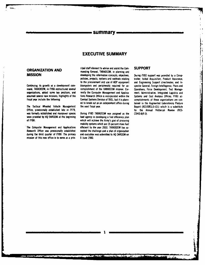
cipal staff element to advise and assist the Corn- SUPPORTORGANIZATION AND manding General, TARADCOM, in planning and
MISSION developing the information concepts, objectives, During FY80 support was provided by a Coutp-policies, projects, systems and methods relating troller; Initial Acquisition, Product Assurance,to the procurement and use of ADP equipment and Engineering Support directorates; and In-
Continuing its growth as a development com- (computers and peripherals) required for ac- spector General, Foreign Intellegence, Plans andmand, TARADCOM, in FY80 restructured several complishment of the TARADCOM mission. Cur- Operations, Force Development, Test Manage-organizations, added some key positions, and rently the Computer Management and Applica- ment, Administrative, Integrated Logistics andassumed several new missions. Highlights of the tions Research Office is incorporated within the Systems and Cost Analysis Offices. FY80 ac-fiscal year include the following: Combat Systems Division of TASL, but it is plann- complishments of these organizations are con-
ed to break out as an independent office during tained in the Augmented Laboratorory PostureThe Tactical Wheeled Vehicle Management the next fiscal year. Report (RCS-DRCLD-lO1) which is a substituteOffice, provisionally established late in FY79, for the Annual Historical Review (RCS-was formally established and manpower spaces During FY80 TARADCOM was assigned as the CSHIS-6(R-3).were provided by HQ DARCOM at the beginning lead agency in developing a fuel efficiency planof FY80. which will achieve the Army's goal of procuring
mobility systems which are15 percent more fuelThe Computer Management and Applications efficient by the year 2000. TARADCOM has ac-Research Office was provisionally established cepted the challenge and a plan of organizationduring the third quarter of FY80. The primary and execution was submitted to HQ DARCOM onmission of this new office is to serve as a prin- 9 June 1980.
1r
I
........-
summary
ORGANIZATIONASSIGNMENTS/RESPONSIBILITIES
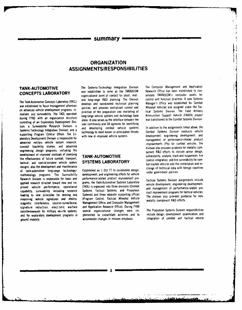
TANK-AUTOMOTIVE The Systems/Technology Integration Division The Computer Management and Application
CONCEPTS LABORATORY was established to serve as the TARADCOM Research Office has been established to con-
organizational point of contact for short-, mid-, solidate TARADCOM's computer assets for
and long-range R&D planning. The Division control and function priorities. A new Systemswas established to focus management attention deveiops and coordinated technical planning Manager's Office was established for Combaton advanced vehicle development programs in- policies, and provides centralized control and Wheeled Vehicles and assigned under the Tac-itiatives, and survivability. The TACL operated direction of the preparation and marketing of tical Systems Division. The Field Artilleryduring FY0s with an organization structure long-range vehicle systems and technology base Ammunition Support Vehicle (FAASV) projectconsisting of an Exploratory Development Divi- plans, It also serves as the interface between the was transitioned to the Combat Systems Division.
user community and DA agencies for identifyingsion, a Survivability Research Division, a and developing combat vehicle systems In addition to the assignments listed above, the
Systems/Technology Integration Division, and a technology to meet known or anticipated threats Combat Systems Division conducts vehicle
sportiror m De o ntr iOi e. resp ie fr with new or improved vehicle systems. development, engineering development, andploratory Development Division is responsible for management of performance-related productadvanced military vehicle system research, improvements (PIs) for combat vehicles. Theconcept feasibility studies, and advanced division also provides guidance for metallic com-
engineering design programs, including the ponent R&D efforts to include armor design,
development of improved methods of assessing TANK-AUTOMOTIVE vulnerability, analysis, track and suspension, firethe effectiveness of future combat, transport,tactical, and special-purpose vehicle system SYSTEMS LABORATORY control integration, and fire survivability for com-
bat tracked vehicles and the compilation and ex-designs; also the development and maintenanceof tank-automotive long-range technology/ Established on I Oct 77 to consolidate design, change o technical data with foreign countries
methodology programs. The Survivability development, and engineering efforts for vehicle
Research Division is responsible for basic and performance-related product improvement pro- Tactical Systems Division assignments include
applied research directed toward new and im- grams, the Tank-Automotive Systems Laboratory vehicle development, engineering development,
proved vehicle performance, operational (TASL) is organized into three divisions (Combat and management of performance-related pro-
capability, survivability including research Systems, Tactical Systems, and Propulsion
leading to new principles for sensing and Systems) and three separate supporting offices duct iovement programs for i vc
measuring vehicle signatures and electro- (Program Control, Tactical Wheeled Vehicle Tetdiv o po e s uD foronon-
magnetic interference, counter-surveillance, Management Office, and Computer Management
signature reduction, electonic warfare and Application Research Office). During FY80
countermeasures for miitary vei,icle systems, several organizational changes were im- The Propulsion Systems Division responsibilities
and for exploratory development programs in plemented to consolidate activities and to include design, development, qualification, and
ground mobility. accomodate changes in mission emphasis. integration of combat and tactical vehicle
2
summary
engines, transmissions, diagnostic and prog- planning, directing, and controlling the research, Fire Support Team Vehicle (FISTV); putting thenostic equipment, and electrical power distribu- design, and development efforts for the High Ground Laser Locator Designator (GLLD) in-tion and management systems. The compilation Mobility/Agility Test Bed Vehicle (HIMAG) and tegrated in the ITV day/night optical system,and exchange of technical data with U.S.-based High Survivability Test Vehicle - Lightweight Vehicle Positioning Equipment (VPE), and com-industry is also provided. (HSTV-L) systems under the overall program munications equipment under armor on the
guidance and funding support of DA Systems M113AI baseline vehicle; and fielding thisThe Program Control Office has the mission for Manager. system.providing budget and program support servicesto the Systems Laboratory and for administeringthe TARADCOM cost reduction, military adapta-tion of commercial items (MACI), and manufac- PROJECT MANAGER -turing methods and technology (MM&T) pro- IMPROVED TOW VEHICLEgrams.
The Tactical Wheeled Vehicle Management This Project Manager manages the expediteddevelopment, procurement. fielding, and sup-
Office provides improved control and cost- dopt procementfeldinhad p-effective management of the Army's Tactical port of the improved TOW(tube-launched opticalWheeled Vehicle Fleet. tracked wire command-link-guided) vehicleW isystems. Major program emphasis is to provide
armor protection to the TOW anti-tank missilesystem and crew within three years from project
PRODUCT MANAGER - approval. This is to be accomplished by develop-ing a new weapon station which integrated the
ARMORED COMBAT TOW system and the M I13AI Armored Personnel
VEHICLE TECHNOLOGY Carrier (APC) with minimal change.
The Product Manager - Armored Combat Vehicle The Office also manages the expedited develop-Technology (PM-ACVT) Office is responsible for ment, procurement, fielding and support of a
Ii
-. - - -- , - z. -- . " . .... . 1. l l . . .. .. : , ' mi:,....2.. ,,...k ,.... ' ;' " ., .. - ,, ;,ka i. ,.... : [ .- 3,i
PERSONNEL AND FISCAL RESOURCES
PERSONNEL
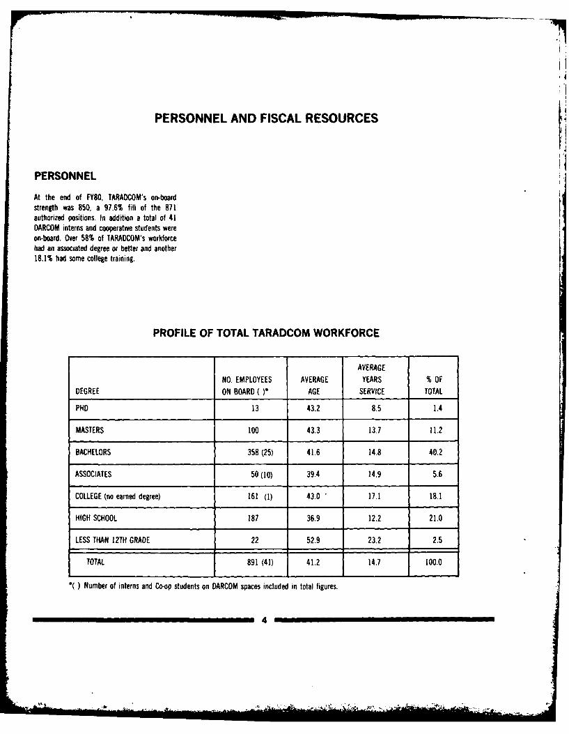
At the end of FY80, TARAOCOM's on-boardstrength was 850, a 97.6% fill of the 871authorized positions. In addition a total of 41
DARCOM interns and cooperative students wereon-board. Over 58% of TARADCOM's workforcehad an associated degree or better and another18.1% had some college training.
PROFILE OF TOTAL TARADCOM WORKFORCE
AVERAGE
NO. EMPLOYEES AVERAGE YEARS % OFDEGREE ON BOARD ( )* AGE SERVICE TOTAL
PHD 13 43.2 8.5 1.4
MASTERS 100 43.3 13.7 11.2
BACHELORS 358 (25) 41.6 14.8 40.2
ASSOCIATES 50 (10) 39.4 14.9 5.6
COLLEGE (no earned degree) 161 (1) 43.0 17.1 18.1
HIGH SCHOOL 187 36.9 12.2 21.0
LESS THAN 12TH GRADE 22 52.9 23.2 2.5
TOTAL 891 (41) 41.2 14.7 100.0
( ) Number of interns and Co-op students on DARCOM spaces included in total figures.
4
Olin _
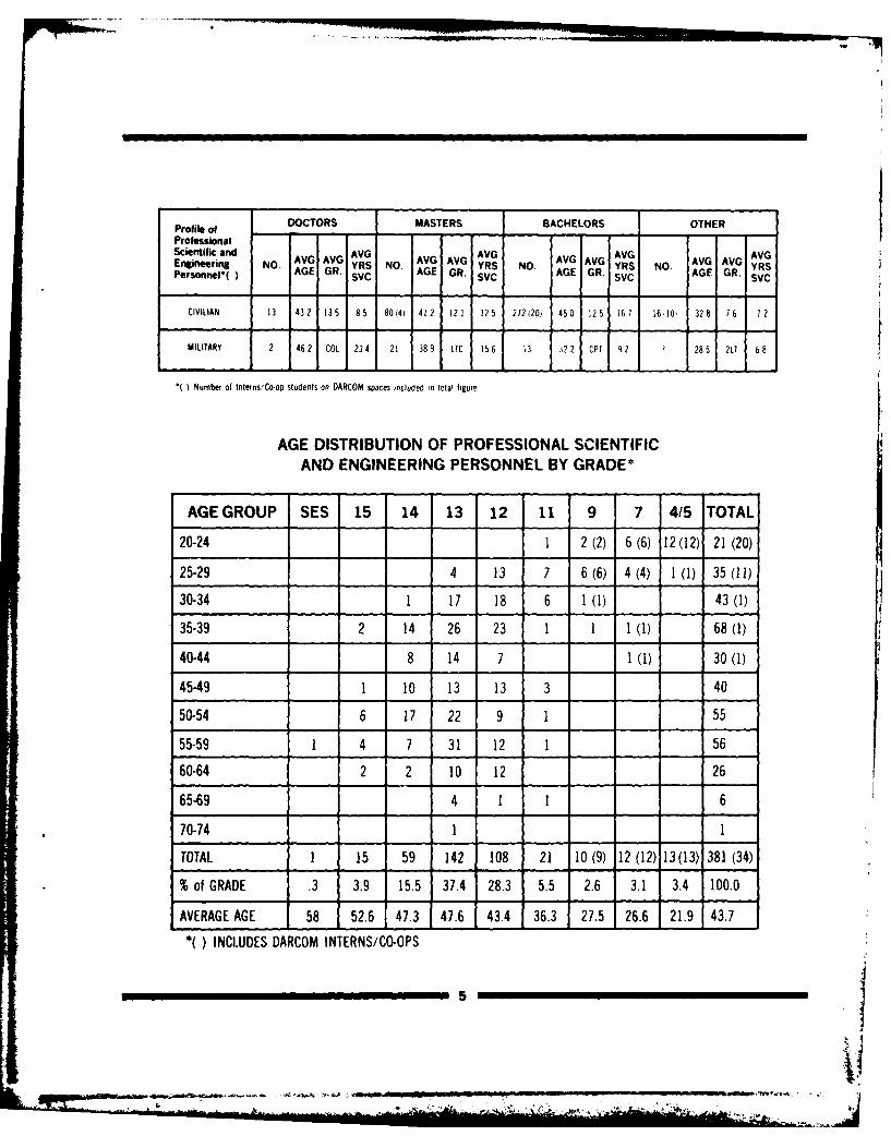
Profile of DOCTORS MASTERS BACHELORS OTHER
ProfessionalScientific andEngineerin NO AVG AVG AVG AVG V AVG AVG AVG AVG VG AVG AVGPiersnl) AGE GR. YRS NO. AG AG YRS NO. YRS NO A YRSPersonnel( AGE GR. SVC AGE GR. SVC AGE GR. SVC
CIVILIAN 13 432 135 85 80(4) 412 121 2 5 272(20) 450 125 167 16110 328 76 72
MILITARY 2 46 2 COL 234 21 389 LTC 156 13 :22 CPT 92 3 2805 2L 68
( ) Number of Interns/Co-op students on DARCOM spaces included in total fiRure
AGE DISTRIBUTION OF PROFESSIONAL SCIENTIFICAND ENGINEERING PERSONNEL BY GRADE*
AGE GROUP SES 15 14 13 12 11 9 7 4/5 TOTAL
20-24 1 2(2) 6 (6) 12(12) 21(20)
25-29 4 13 7 6 (6) 4 (4) 1 (1) 35 (11)
30-34 1 17 18 6 1 (1) 43 (1)
35-39 2 14 26 23 1 1 1 (1) 68 (1)
40-44 8 14 7 3(1) 30 (1)
45-49 1 10 13 13 3 40
50-54 6 17 22 9 1 55
55-59 1 4 7 31 12 1 56
60-64 2 2 10 12 26
65-69 4 1 1 6
70-74 1 1
TOTAL 1 15 59 142 108 21 10 (9) 12 (12) 13(3) 381 (34)
% of GRADE .3 3.9 15.5 37.4 28.3 5.5 2.6 3.1 3.4 100.0
AVERAGE AGE 58 52.6 47.3 47.6 43.4 36.3 275 26.6 21.9 43.7
( ) INCLUDES DARCOM INTERNS/CO-OPS
_ __. .54
summary
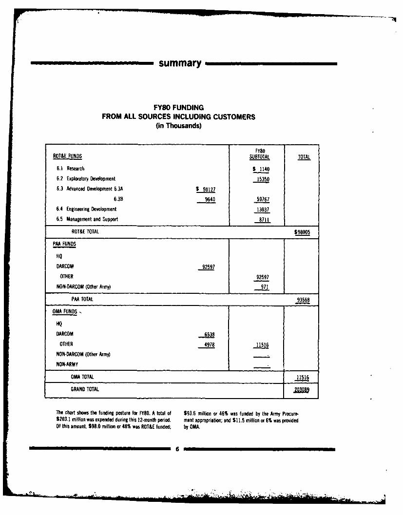
FY80 FUNDINGFROM ALL SOURCES INCLUDING CUSTOMERS
(in Thousands)
FY80
RDT&E FUNDS SUBTOTAL TOTAL
6.1 Research $ 1140
6.2 Exploratory Development 15350
6.3 Advanced Development 6,3A $ 50127
6.3B 9640 59767
6.4 Engineering Development 13037
6.5 Management and Support 8711
ROT&E TOTAL $98005
PAA FUNDS
HQ
DARCOM 92597
OTHER 92597
NON-DARCOM (Other Army) 971
PAA TOTAL 93568
OMA FUNDS
HQ
DARCOM 6538
OTHER 4978 11516
NON-DARCOM (Other Army)
NON-ARMY
OMA TOTAL 11516
GRAND TOTAL _
The chart shows the funding posture for FY80. A total of $93.6 million or 46% was funded by the Army Procure-$203.1 million was expended during this 12-month period. ment appropriation; and $11.5 million or 6% was providedOf this amount, $98.0 million or 48% was RDT&E funded; by OMA.
6
IN.
summary
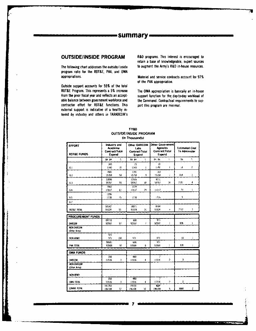
OUTSIDE/INSIDE PROGRAM R&D programs. This interest is encouraged toretain a base of knowledgeable, expert sources
The following chart addresses the outside/inside to augment the Army's R&D in-house resources.program ratio for the RDT&E, PAA, and OMAappropriations. Materiel and service contracts account for 97%
of the PAA appropriation.Outside support accounts for 55% of the totalRDT&E Program. This represents a 5% increase The OMA appropriation is basically an in-housefrom the prior fiscal year and reflects an accept- support function for the day-to-day workload ofable balance between government workforce and the Command. Contractual requirements to sup-contractor effort for RDT&E functions. This port this program are minimal.external support is indicative of a healthy in-terest by industry and others in TARADCOM's
FY80OUTSIDE/INSIDE PROGRAM
(in Thousands)
EFFORT Industry and Other DARCOM Other GovernmentAcademia Labs Agencies Estimated Cost
ContractTotal Contract/Total Contract/Total To AdministerRDT&E FUNDS Expend Expend Expend
345 15 30
6 1 1140 30 1140 1 1140 3 18 2
7681 1391 10362 15350 50 15350 9 15350 454 3
33098 12926 823163 59767 55 59767 22 59167 14 2181 4
7942 373964 13037 61 13031 29 13037 70 1
1296
65 1730 75 1130 13 9
61
50362 18071 8364
RDT&E TOTAL 91024 55 9/024 20 91024 9 2732 3
PROCURE MENT FUNDS89110 608 971
DARCOM 92597 91 92597 7 92597 1 926 I
NONOARCOM(Other A(my)
971
NON-ARMY 971 100 971 91/ /0 1
90681 608 91
PAA TOTAL 93568 97 93568 6 93568 1 936 I
OMA FUNDS350 480 2
DARCOM 11516 3 11516 4 11516 0 0
NON DARCOM(Other Army)
NON-ARMY
350 460 ,
OMA TOL 11516 3 11516 4 11516 0 0
141393 19159 331GRAND TOTAL 196108 72 196108 /0 196108 5 3668 2
summary
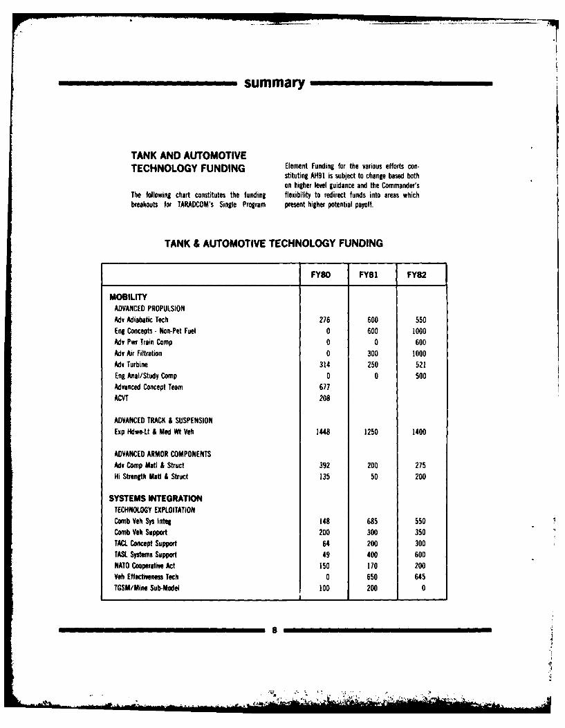
TANK AND AUTOMOTIVETECHNOLOGY FUNDING Element Funding for the various efforts con-
stituting AH91 is subject to change based bothon higher level guidance and the Commander's
The following chart constitutes the funding flexibility to redirect funds into areas whichbreakouts for TARADCOM's Single Program present higher potential payoff.
TANK & AUTOMOTIVE TECHNOLOGY FUNDING
FY80 FY81 FY82
MOBILITYADVANCED PROPULSIONAdv Adiabatic Tech 276 600 550Eng Concepts- Non-Pet Fuel 0 600 1000Adv Pwr Train Comp 0 0 600Adv Air Filtration 0 300 1000Adv Turbine 314 250 521Eng Anal/Study Comp 0 0 500Advanced Concept Team 677ACVT 208
ADVANCED TRACK & SUSPENSIONExp Hdwe-Lt & Med Wt Veh 1448 1250 1400
ADVANCED ARMOR COMPONENTSAdv Comp Matl & Struct 392 200 275Hi Strength Matl & Struct 135 50 200
SYSTEMS INTEGRATIONTECHNOLOGY EXPLOITATIONComb Veh Sys Integ 148 685 550Comb Veh Support 200 300 350TACL Concept Support 64 200 300TASL Systems Support 49 400 600NATO Cooperative Act 150 170 200Yeh Effectiveness Tech 0 650 645TGSM/Mine Sub-Model 100 200 0
8
K.. -
i4
summary
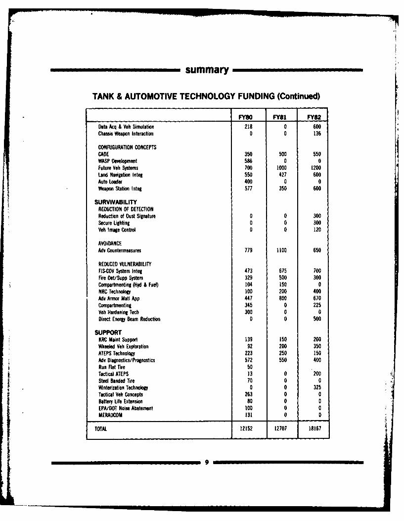
TANK & AUTOMOTIVE TECHNOLOGY FUNDING (Continued)
FY60 FY81 FY82Data Acq & Veh Simulation 218 0 600Chassis Weapon Interaction 0 0 136
CONFUGURATION CONCEPTSCADE 350 500 550WASP Development 586 0 0Future Veh Systems 700 1000 1200Land Navigation Integ 550 427 600Auto Loader 400 0 0Weapon Station Integ 577 350 600
SURVIVABILITYREDUCTION OF DETECTIONReduction of Dust Signature 0 0 300Secure Lighting 0 0 300Veh Image Control 0 0 120
AVOIDANCEAdv Countermeasures 779 1100 650
REDUCED VULNERABILITYFIS-COV System Integ 473 675 700Fire Det/Supp System 329 500 300Compartmenting (Hyd & Fuel) 104 150 0NBC Technology 100 200 400Adv Armor Matl App 447 800 670Compartmenting 345 0 225Veh Hardening Tech 300 0 0Direct Energy Beam Reduction 0 0 500
SUPPORTKRC Maint Support 139 150 200Wheeled Veh Exploration 92 200 350ATEPS Technology 223 250 150AMv Diagnostics/Prognostics 572 550 400Run Flat Tire 50Tactical ATEPS 13 0 200Steel Banded Tire 70 0 0Winterization Technology 0 0 325Tactical Veh Concepts 263 0 0Battery Life Extension 80 0 0EPA/DOT Noise Abatement 100 0 0MERADCOM 131 0 0
TOTAL 12152 12707 18167
9
summary
NOTEWORTHY TECHNICAL CONTRIBUTIONS
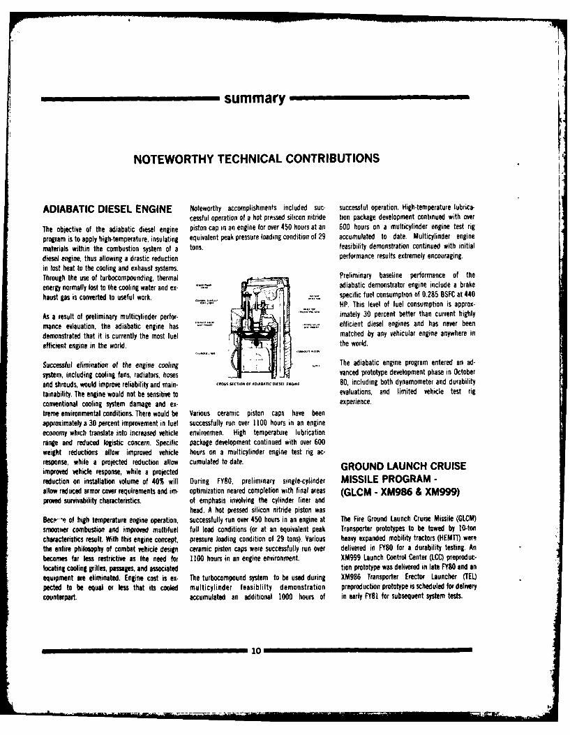
ADIABATIC DIESEL ENGINE Noteworthy accomplishments included suc- successful operation. High-temperature lubrica-cessful operation of a hot pressed silicon nitride tion package development continued with over
The objective of the adiabatic diesel engine piston cap in an engine for over 450 hours at an 600 hours on a multicylinder engine test rig
program is to apply high-temperature, insulating equivalent peak pressure loading condition of 29 accumulated to date. Multicylinder engine
materials within the combustion system of a tons. feasibility demonstration continued with initial
diesel engine, thus allowing a drastic reduction performance results extremely encouraging.in lost heat to the cooling and exhaust systems.Through the use of turbocompounding, thermal Preliminary baseline performance of the
energy normally lost to the cooling water and ex- .-. , adiabatic demonstrator engine include a brakehaust gas is converted to useful work. ispecific fuel consumption of 0.285 BSFC at 440
hastgs scovetd ousfu.or.HP. This level of fuel consumption is approx-
As a result of preliminary multicylinder perfor- imately 30 percent better than current highlymance evlauation, the adiabatic engine has efficient diesel engines and has never been
demonstrated that it is currently the most fuel matched by any vehicular engine anywhere in
efficient engine in the world. the world.
Successful elimination of the engine cooling The adiabatic engine program entered an ad-
system, including cooling fans, radiators, hoses vanced prototype development phase in October
and shrouds, would improve reliability and main- CROSS SECTOR OF ADAATC DIESEL EN5 80, including both dynamometer and durabilitytainability. The engine would not be sensitive to evaluations, and limited vehicle test rigconventional cooling system damage and ex- experience.treme environmental conditions. There would be Various ceramic piston caps have beenapproximately a 30 percent improvement in fuel successfully run over 1100 hours in an engineeconomy which translate into increased vehicle environmen. High temperature lubricationrange and reduced logistic concern. Specific package development continued with over 600weight reductions allow improved vehicle hours on a multicylinder engine test rig ac-response, while a projected reduction allow cumulated to date. GROUND LAUNCH CRUISEimproved vehicle response, while a projectedreduction on installation volume of 40% will During FY80, preliminary single-cylinder MISSILE PROGRAM -allow reduced armor cover requirements and im- optimization neared completion with final areas (GLCM -XM986 & XM999)proved survivability characteristics, of emphasis involving the cylinder liner and
head. A hot pressed silicon nitride piston wasBec--e of high temperature engine operation, successfully run over 450 hours in an engine at The Fire Ground Launch Cruise Missile (GLCM)smootner combustion and improved multifuel full load conditions (or at an equivalent peak Transporter prototypes to be towed by 10-toncharacteristics result. With this engine concept, pressure loading condition of 29 tons). Various heavy expanded mobility tractors (HEMTT) werethe entire philosophy of combat vehicle design ceramic piston caps were successfully run over delivered in FY80 for a durability testing. Anbecomes far less restrictive as the need for 1100 hours in an engine environment. XM999 Launch Control Center (LCC) preproduc-locating cooling grilles, passages, and associated tion prototype was delivered in late FY8O and anequipment are eliminated. Engine cost is ex- The turbocompound system to be used during XM986 Transporter Erector Launcher (TEL)pected to be equal or less that its cooled multicylinder feasiblilty demonstration preproduction prototype is scheduled for deliverycounterpart, accumulated an additional 1000 hours of in early FY81 for subsequent system tests.
10

summary
GLCM Transporter
A second major effort directed at achieving a NBC PROTECTION This new component represents a departureproduction contract award will be initiated in m establishedFY81 and initial deliveries are scheduled to Hybrid Collective Protective foiestablishe pohy in nearbelin i mi-FY8. Euip entbiological, and chemical (NBC) protection and anbegin in mid-FY82. Equipment advancement in the state-of-the-art for US
armored vehicles.In FY79, TARADCOM completed the design and The commitment to develop Hybrid Collectivefabrication of one pilot "A" trailer, a first Protective Equipment (HCPE) has culminated in Information on the development of a positivegeneration GLCM transporter to be towed by the the signing of a contract on 15 July 1980 for full pressure type protective system for combatstandard military 5-ton tractor. As a result of scale engineering development. Delivery of 36 vehicles gleaned from the FY79 Data Gap Pro-Pilot "A" tests, revised system loads and a revis- preproduction prototypes for specific vehicle gram as to the feasibility of overpressure, vis-a-ed mobility operating scenario, a second genera- (FAAR, US ROLAND, XM-1) engineering tests is vis occasional open-hatch battlefield tactics,tion GLCM transporter was designed to be towed projected to start in mid-FY82. substantiated in earlier investigations conductedby the HEMTT. Fabrication of seven prototypeswas initiated in late FY79 consisting of four pilotvehicles, one durability test vehicle and two pre- HYBRID COLLECTIVE PROTECTIVE UNIT
production prototypes (PPP), a TEL, and a LCC. A Alt#.......
The GLCM is an Air Force Program chartered byDOD under the Joint Cruise Missiles ProjectOffice, Washington, D. C. .... O ... "°"
TARADCOM was selected in late 1978 to be anassociate GLCM contractor for design anddevelopment of two transporters: The TEL andthe LCC. This effort also encompassed fabrica-tion of prAotypls and pilot vehicles, generationof mobiity data and participation in an advisorycapacity for design of all GLCM mobile equip-ment.
&2- -4,11
71
summary
in FY78, and gave impetus to the concept of Final preparations were completed for laboratory WASP II is a small one-man, kinestheticallymodularized, hybrid collective protective system environmental and performance testing during controlled individual mobility device developingfor combat vehicle, combining the unrestricted FY80 for performance testing scheduled to be its lifting force from a modified cruise missileenvronment of the overpressure system with the conducted during FY81. engine, which can be operated by non-aviation
flexibility of ventilated facepiece protection. rated military personnel.The optical fire sensor system is designed todetect explosions or fires within armored person- Technical feasibility of Williams Anal Systems
nel carriers, discriminate as to the type or inten- Platform (WASP) II was demonstrated on 17 AprNBC Agent Resistant Paint sity of the blaze to avoid false alarms, and 80 by the first manned tether free operation at
automatically actuate the fire extinguisher to Walled Lake, MI. To date, 18 tether free opera-As a further enhancement to chemical warfare put out the fire. tions have been performed successfully with theprotection, chemical agent restraint paints are vehicle attaining speeds of 40-45 mph at anbeing seriously considered for application on the Major draft specifications for the sensor systems altitude of 60 feet and up to five and a halfinterior and exterior of all combat vehicles. This have been coordinated and are being updated in- minutes in duration. This vehicle has calculatedwill allow much simpler decontamination pro- to final form. capabilities of speeds up to 65 mph, 4,000 feetcedures (i.e. soap and washdown) in lieu of the in altitude for 20 minutes in duration.presently used corrosive DS-2 solution.
The past 12 months of effort has resulted in theFor the interiors of combat vehicles, two- fabrication of two WASP II vehicles.component epoxy coating systems are being FIRST MANNED TETHERrecommended. The epoxy paints cannot be used FREE FLIGHTS OF All test flights were performed with one of thefor final overcoat on vehicle exteriors due to vehicles and proceeded according to a rigid plan.their breakdown with loss of chemical agent WASP II First the vehicle was held by a gimbalresistance properties under extended periods ofexposure to sunlight. The US Army is presentlytesting the more sophisticated and expensivetwo-component polyurethane coating system.Present indications are that it will meet Armyrequirements.
Contractor/sub-contracts will require physicaldemomation/instruction and assurance bygovernment specialists to demonstrate thesimplicity of applying two-component agentresistant coatings versus presently used alkydcootings. Such a demonstration is being con-ducted at Tonole Army Depot in the Fall of 80under the auspices of the Development ProjectOffice for Vehicle NBC Protection.
AUTOMATIC OPTICAL FIREDETECTION ANDSUPPRESSION SYSTEM
Dinng FM.0 pretp opkacl fnr snw and-ni c b cmbsac aempfifir were
cived., Tham wiN he used to snuff out a fire in WASP 1I on its first tether free operationa boj vehic faitr them the e can Mink. 17 April 1980
12
summary
mechanism, allowing rotation motion only in The STE/T program to expand the STE/ICE con- ware was performed during late Aug and earlyorder to check rotational stability. Next, it was cept to turrets to support the XM] and FVS Sep 80. The test utilized the detection systemflown in a tethered mode. vehicles resulted in development of two addi- mounted aboard the M60 tank to detect HH3-E
tional modules, a Controllable Interface Box helicopters operating alone and in multiples ofThis high risk program was completed three (CIB), and a Set Communicator (SET COM), two and three. The HH3-E was chosen because ofmonths ahead of schedule and within budget, which when combined with an expanded its similarity to the Soviet HIMD-D in size, weightCurrently plans are being formulated for a Simplified Test Equipment/Internal Combustion and configuration. The helicopters flew ant-follow-up program to determine the military Engine (STE/ICE) becomes the core of the armor scenarios against the M60 operating alonepotential of the WASP II vehicle. STE/T. The CIB enables the basic STE/ICE to with other M60's and MI13AI's.
address several hundred test points required totest the turret, and the SET COM provides anexpanded communication link between the test Preliminary measurements indicate that detec-set and the mechanic. In operation, the CIB pro- tion ranges sufficient to detect, locate, identify,
SIMPLIFIED TEST vides the interface between the turret and the and counter aircraft carrying antiarmor missilesSTE/ICE set, and the SET COM enables are achieveable from onboard operating combat
EQUIPMENT TRACKED automated step by step instructions for the vehicles. The system shows particular promise as
VEHCILE mechanic to perform test procedures to locate a means for passive identification friend or toethe fault (IFF) and beyond-the-line-of-sight detection of
Simplified Test Equipment Tracked Vehicle helicopters.(STE/i) currently is being adapted to support theIFV/CFV Fighting Vehicle System (FYS) vehicles. An effort is also in progress to utilize the eleva-Delivery of units for FVS initial fielding is tion and azimuth information available from thescheduled for FY82. ACOUSTICALLY BASED system to lay a crew served weapon on or near
the threat An M60 stabilization system has beenUpon completion of this program, STET will DETECTION OF AIRBORNE modified to provide the electro-hydraulic inter-become the standard test system for all combat ANTI-ARMOR THREATS face with the microprocessor out put of thevehicles until the second generation system, threat detection system.Simplified Test Equipment/Expandable, STE/X), During the past years, the technical feasibility ofbecomes available. The decision to apply STE/T detecting and locating attack helicopters from ato the XMl resulted in the replacement of five buttoned up combat vehicle was demonstrated.XM1 peculiar test sets which has accelerated the The concept uses technological advances inArmy program for standardization of multi- acoustic signal processing to passively detect,purpose test sets by at least 10 years. Five STE/T locate, and identify rotary wing aircraft withprototypes were developed with capability to sufficient accuracy and range to give the combatsupport both the turret and the hull, including vehicle and advantage in an engagementthe AGT 1500 turbine engine. The system was scenario.successfully demonstrated in mid-SO. Thirty-oneSTE/T sets have been procured for the XM1 dur- Following successful laboratory demonstrations,ing DT/OT III beginning in Sep 80. a field test of the advanced breadboard hard-
13
summary
RESOURCES SAVINGS/VALUE ENGINEERING
For the first time in its history, the TARADOM Studies have been completed on the fifthValue Engineering (VE) program met all three of compressor stage. The final casting of the fifthits goals in FY80. They included 25 value El stage will be submitted to TACOM in secondengineering proposals (VEPs), three value quarter FY81 for engine testing. The first andengineering change proposals (VECPs), and a sav- , , second stages are currently undergoing invest-ings of $2.OOM. Actual accomplishments were ment casting/tooling construction.31 VEPs and 5 VECPs, and a savings of $2%..million.
UPSCALING ADVANCEDSome of the validated programs are: POWDER METALLURGYIMPROVED FOUNDRY .c,. PROCESSES
CASTINGS PROGRAM .... Powder metallurgy has been tested for the pro-duction of high performance gears. The ability to
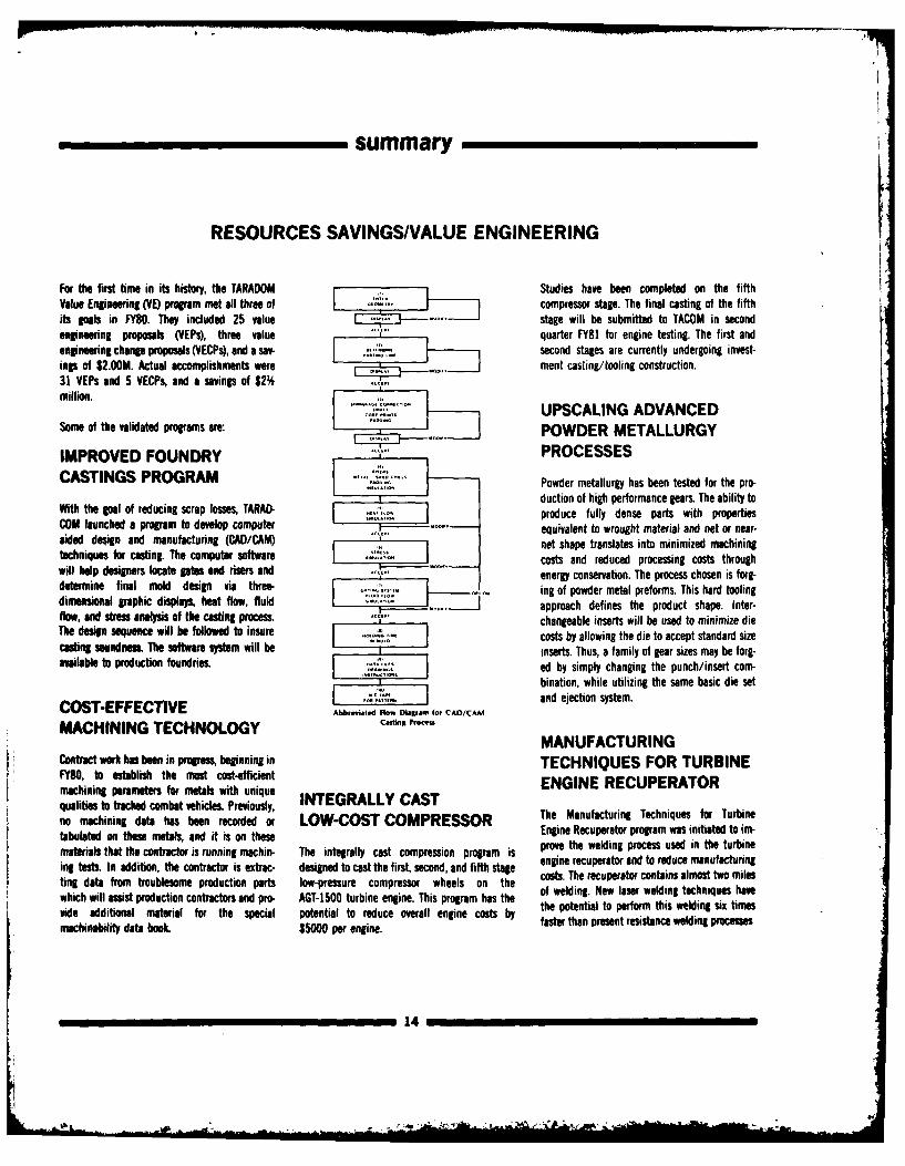
With the goal of reducing scrap losses, TARAD- produce fully dense parts with propertiesCOM launched a program to develop computer equivalent to wrought material and net or near-aided design and manufacturing (CAD/CAM) net shape translates into minimized machiningtechniques for casting. The computer software costs and reduced processing costs throughwill help designers locate gates and risers and energy conservation. The process chosen is forg-determine final mold design via three- .. ing of powder metal preforms. This hard toolingdimensional graphic displays, heat flow, fluid J approach defines the product shape. Inter-flow, and stress analysis of the casting process. ',. changeable inserts will be used to minimize dieThe design sequence will be followed to insure - - costs by allowing the die to accept standard sizecasting soundness. The software system will be inserts. Thus, a family of gear sizes may be forg-available to production foundries. ed by simply changing the punch/insert com-
....________bination, while utilizing the same basic die setCO T FF CTVE CDand ejection system.COST-EFFECTIVE Ab,...,.., o. ,..m ,, CAD/CAM
MACHINING TECHNOLOGY C.,6,g fo -
MANUFACTURINGc t work has been in progress, beginning in TECHNIQUES FOR TURBINE
FY80, to establish the most cost-efficient ENGINE RECUPERATORmachining parameters for metals with uniquequalities to tracked combat vehicles. Previously, INTEGRALLY CASTno machining data has been recorded or LOW-COST COMPRESSOR The Manufacturing Techniques for Turbine !tabulated on these metals, and it is on these Engine Recuperitor program was initiated to im-materials that the contractor is running machin- The integrally cast compression program is prove the welding process used in the turbineing tests In addition, the contractor is extrac- designed to cast the first, second, and fifth stage engine recuperator and to reduce manufacturingting data from troublesome production parts low-pressure compressor wheels on the costs. The recuperat contains almost two mileswhich will assist production contractors and pro. AGT-1500 turbine engine. This program has the of welding. New laser welding techniques havethe potential to perform this welding six timesvide additional material for the special potential to reduce overall engine costs by fester than presentrosistanc welding procstesmchinability data book. $5000 per engine. fs
14
summary
Phase I of the program verified the laser as a are a satisfactory replacement for the standard Component evaluation is currently underwayviable method of joining Inconel 625 for the metal connector. All MPOEC's remain installed with engine performance evaluation scheduledrecuperator and verified that the system can pro- on those vehicles in their present locations and during first quarter FY81.duce an acceptable weld. The developed process are subject to periodic observation. The MPOEC'swill be faster and less expensive than the stan- are being implemented through the M113,dard welding process. It is estimated that $1000 M 13PIP and FVS offices. The new drawings willsavings can be realized for each recuperator. A allow the initiation of an ECP for MPOE connec- 1500 HP DIESEL ENGINEprototype laser welder is being purchased to tors. This project offers savings in weight and DEVELOPMENTverify the process in a production environment cost.If successful, a similar laser welding system The 1500 horsepower diesel engine project,could handle the entire production requirement initiated in Mar 79, objective is to continuefor the XMI AGT-1500 engine recuperator. By development of a diesel engine option until theusing the laser welding system, it is estimated Army Ground Turbine (AGi) 1500 has fullyan additional $2 million can be saved in capital demonstrated satisfactory operation in the XMinvestment. Reduction of health hazard fromnoxious welding fumes is another advantage. ARMY GROUND TURBINE tank.
(AGT) 1500 FUEL ECONOMY Improvements of the AVCR-1360 diesel are beingPROGRAM pursued via development of variable area turbo.
chargers (VATS) and variable speed cooling fans.MOLDED PLASTIC The Army Ground Turbine (AG!) 1500 Fuel The VATS have been fabricated and subjected to
Economy Program objective is to reduce the bench tests from which optimization of the tur-ORDNANCE ELECTRICAL mission fuel consumption. This fuel economy bine and compressor wheel profiles have been
CONNECTOR improvement will be accomplished by decreas- derived. Final wheel configurations are beinging the idle fuel flow, achieving the greatest fabricated for operation on engines beginning in
Molded Plastic Ordnance Electrical Connector percentage of fuel reduction in the 40-50 mid-FY81.(MPOEC) project purpose is to develop an percent power range, and obtaining a mission-optional material to replace the current steel weighted 10 percent average reduction in The variable speed cooling fan system has beenand aluminum ordnance electrical connectors specific fuel consumption throughout the engine fabricated and is undergoing bench durabilitywith plastic molded connectors to eliminate cor- operating range. Additional goals are improved and control tests. Results indicate that designrosion problems and reduce weight and cost. RAM-D factors and reduced engine acquisition objectives are being achieved.Connectors were fabricated from thermo-plastic cost. During FY80 detail design of the enginepolyester "Valox 420" and successfully com- was completed, and all hardware procured or The second program phase, initiated in mid-pleted validation and laboratory testing. The new fabricated for assembly of the first test engine in FY80, provides for update and rebuild of twoconnectors are interchangeable, intermateable, First Quarter FY81. The combustor test rig existing engines, laboratory development andand intermuntable with the existing metal con- designed for the AGT-1500 combustion system, durability tests, fabrication of two new engines,nectors. The field tests were conducted on 15 was completed and testing initiated. Component integration in two prototype XM1 vehicles andvehicles and the plastic connectors were inter- tests began on the high pressure compressor. automotive test of the diesel powered vehicles.mounted with the steel receptacles at -650F Recuperator core testing was completed and Preliminary layouts have been completed identi-(-540C) on M151 jeeps and on M113 personnel design selection made. fying the engine and vehicle changes requiredcarriers in Alaska and at Yuma Proving Grounds for integration and long lead items for theon the Ml 13, M60, M818 and M54 vehicles. The Achievement of program objectives will result in engine rebuilds have been ordered. Laboratoryresults show that after two years there hve been extended range for the XM1I and/or reduced tests are scheduled to begin in May81 and vehi-no failures or deterioration of MPOECs and they fuel supply logistics along with associated costs. cle tests in Jul 81.
15
summary
ADVANCED TECHNIQUES Other accomplishments include five published cost, size, weight, and power consumption com.reports describing the potential application of pared to the incandescent lamps currently inFOR ELECTRICAL POWER ATEPS to Army vehicles. Work also was initiated use.
MANAGEMENT, CONTROL for the reduction of ATEPS system hardware to
AND DISTRIBUTION SYSTEMS enhance its potential for XM! PIP application. TARADCOM was tasked by Department of theArmy (DA) to provide economical blackout units
Advanced Techniques for Electrical Power (markers, stop light, tail light and driving light)
Management, Control, and Distrubtion Systems for application to the full range of commercial
(ATEPS) is an advanced technology procedure substitute tactical vehicles that the Army might
which integrates all electrical power and info- buy in the future.
mation transfer within combat vehicles. It is a AUXILIARY POWER UNITsystems approach which integrates all elec- Laboratory and field tests revealed that the LEDtrical/electronic functions within the vehicle FOR XM1IM60 was ideally suited for blackout lamp application.and includes built-in capabilities for diagnostics Blackout tail, stop marker, and driving lightsand prognostics. The system integration is Development continued on the Auxiliary Power were completely designed. Twelve sets of [EDachieved by using digital multiplexing with Unit (APU) which supplies electrical power for prototypes were fabricated in-house, andmicro-computer control, integrated controls and application to the XMI/M60 tank systems. The evaluated in accordance with MIL-STD- 79.displays and solid state power control switching. APU is a gas turbine driven generator set capable ecCommunication between vehicle subsystems is of delivering 10KW of 28V DC power for low Initial application of LED blackout lamps will beaccomplished by the Multiplex Data Bus. temperature starting of the main engine, silent on the M8?6 telephone truck (288 units). A com-
watch, and maintaining vehicle batteries. FiveTr plete data package has been designed for the
ATEPS hull prototype hardware development was Prototypes were delivered and aboratory/vehicle telephone truck blackout lamp fabrication andinitiated, for installation and evaluation, in a tests initiated, installation. This is currently being revised, priorbaseline XMI prototype in FY80. The hull task, to final approval. Adaptation to other vehicleswith follow-on turret prototype hardware will be by means of revising the tbeephone truckdevelopment, will establish the feasibility of the data package. The complete technical dataATEPS system and allow for its consideration as package (TDP) will be finalized in FY81, and thisan XMI PIP and for other Army vehicle develop- action will constitute the completion of the DAment programs. The ATEPS hull prototype hard- BLACKOUT LAMPS task.ware consists of a bus assembly (data andpower), driver's crew terminal, bus controller/ A follow-on program to expand the application ofremote terminal, and three remote terminals, the new light emitting diode (LED) lamps toInstallation and test in the XMI prototype hull is military vehicles will begin in FY82. This entireplanned for FY81. program will result in a substantial savings in
16
summary
REDIRECTION OF EFFORT
TARADCOM's test fleet and the eight vehicles assembly on both vehicles. Limited testing on
2 TON, 6 x 6, XM963 shipped and stored at Letterkenny Army Depot. these vehicles will be held locally during FY81.SERIES TRUCKS
The contractor furnished the total document- It is estimated that six million dollars would beAt the beginning of FY80, the XM963 Series ation that had been generated on the product required to reactivate the 2 Ton ProductProgram was in a phase-out category due to a improvement contracts plus any and all compo- Improvement Program (PIP) for a period of twolack of requirements for 2 ton trucks until nent hardware. This software and hardware is years. This would result in obtaining a Technical1986 and beyond. currently being stored locally. Data Package for production purposes. The 2
ton tactical fleet would be modernized byThe phase-out period commenced in Sep 79 and Two of the test fleet vehicles have been loaned infusion of PIP trucks, which include improvedwas completed on 30 Jun 80. During this period to TARADCOM's Propulsion Laboratory. This reliability, availability, and maintainability (RAM)limited component testing was conducted, three Laboratory is in the process of conducting and conformance to Federal Regulations onvehicles were updated and eight vehicles were feasibility development study by installing a dif- vehicles,assembled. The three vehicles became part of ferent model transmission and transfer case
3 _K
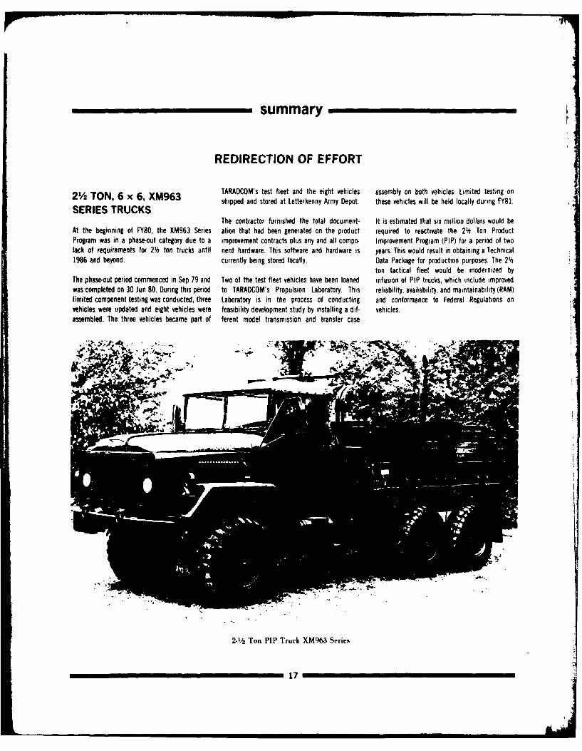
2-'/A Ton PIP Truck XM963 Series
17
summary
MANAGEMENT OF RESOURCES
6.1 BASIC RESEARCH being a joint laboratory ILIR task undertaken tional characteristics of large vehicle structures.with the Engineer Topographic Laboratory (ETL). The holographic fringe data gives the design
Work under "Research in Vehicular Mobility" Several noteworthy technical achievements engineer detailed information about thosewas divided into three major thrust areas. resulted from the program, which has also been regions on the vehicle that have a large displace-"Applied Mobility Research", "Component a valuable tool for recruiting and retaining n-nt amplitude, areas of large stress concentra-Technology Research" and "Countermeasures qualified scientists and engineers. tion, positions of nodal and anti-nodal displace-Research". ment and damping characteristics.
Scanning photoacoustic microscopy, a recently
Field tests were conducted to gather data developed surface and near surfae nondestruc- Excellent quality holograms have been taken of
concerning the off-road turning behavior of tive evaluation technique, fits well with the need the M151 and M 113 vehicles. Several holograms
military tires. The data band is needed to for this type of flaw detection in the newly im- of the M151 engine were quite useful for predic-
develop a mathematical model of a wheeled proved engineering ceramics. These ceramics are ting component fatigue. Significant progress was
vehicle turning in soft soil. A delayed measure- central to advanced engine programs because made toward perfecting techniques for taking
ment state estimation techniques has been their high temperature capabilities will allow holograms of very large structures, solving
developed and implemented. This will be used both higher operating temperatures and reduced significant limitations of the ruby laser holo-
for enhancing our capability of designing improv- cooling requirements for more efficient engines, camera, establishing a methodology for the
ed weapon station control systems. These ceramics are still brittle, however, and quantitative interpretation of holographic fringetheir critical flaws are roughly an order of data in terms of vibrational parameters.
A three dimensional finite element analysis magnitude smaller than critical flaws in metals
model of track pad has been developed and so that improved nondestructive evaluation is
laboratory validation tests have been conducted. essential for their wide spread application. 6.2 EXPLORATORYThis work is expected to lead to improved track
pad life. The detection, recognition, and identification of DEVELOPMENTpotential threat targets is a crucial area of
A methodolog has been developed for the deter- investigation for the survivability of US Army In the diagnostic, prognostic, and electrical
mination and analysis of target and background vehicles. Real time optical and digital correlation systems thrust area, a universal Controllable
interrelatins and their effects on the infrared techniques provide important means for perfor- Interface Box (CI8) configuration was establish-
signatures of both static and dynamic vehicles. ming these surveillance/countersurveillance ed which enabled expansion of STE/ICE to turret
This research effort will yield results which will functions. The cross-correlation of a standard applications for XMI and FVS vehicles. This
contribute to our ability of designing vehicles reference vehicle image with a potential target effort enabled XMI to provide all organizationalwith reduced siglnaturs. image is accomplished using conventional Fest maintenance test support with a single tes
Fourier Transform (FF1) algorithms, systems replacing five special test systems. Thesystem is currently called STE-XMI, but when it
A joint effort with ETL at Ft Belvoir combines is adapted to the FVS vehicles, it will become
IN-HOUSE LABORATORY the results of their acoustic-optical Direct Elec- Simplified Test Equipment-Tracked vehicletronic Fourier Transform (DEFT) device with a (STE-i) which will be the standard test system
INDEPENDENT RESEARCH digital simulation of the same data that is for all combat vehicles until the second genera-(ILIR) obtained at TACOM using digital simulation. tion system Simplified Test Equipment-
Analysis of the Fourier Transform properties of Expandable (STE-X) becomes available. STE-XFourteen research tasas were conducted under these images will establish a measure of effec- will have expansion capabilities to test allthis program in FY80. The technology areas tiveness of vehicle survivability and guide the combat systems. A concept definition for STE-Xrepresented in this research ranged from the development of countersurveillance techniques, has been completed and advanced developmentscanning photoeacoustic microscopy to the study will begin in FY81.of powdered metal matrix composites. Eight of Double exposure pulse holography is a newthe tasks were newly initiated in FY80, with one technique for studying the acoustic and vibra- In FY80, the Vehicle Monitor System (VMS) hard-
_____________________18'
summary
ware and software were modified to provide for hydraulic and fuel lines. Unprotected lines tiveness to defeat various overhead threats.initial prognostic capability to start engine are extremely vulnerable to rupture and ignition(electrical), ability to stop vehicle (brakes), resulting in an explosive fire. Lines are par- An advanced tank conf~guration assessment wascooling system performance and air filter perfor- ticularly hazardous when located in an area out- completed, and preparation for the award of amance. A new software program was written to side the view of optical fire sensors. This system future close combat vehicle contractb for con-enable APG to determine, by test, the prognostic will provide fire suppressant jacketing which ceptual designs was finalized. Conceptualpotential of the STE/ICE diagnostic connector when ruptured will supply a suppressant cloud designs of XMI derivative tank with externalassembly on the FVS and M113A1 vehicles. (probably a dry powder chemical agent suspend- main gun were completed. The initial scope of
ed in a thisogelled HALON) precisely at the point work and cost estimates for a tank technologyThe Fire Detection and Suppression Technology of the rupture. The advantages of this approach test bed (phase 1) was accomplished. TechnicalProgram objectives are to provide state-of-the-art are its ability to operate independent of the discussions with Sweden. Germany and the UKfire detection and suppression componentry for primary optical detection and suppression on future vehicle design, and research on futureexisting and future combat vehicles. The system, and the localized activation at the point vehicle crew sizes and task assignments were in-program goals include (1) the investigation of of origin of the fire (successful suppression itiated. A feasibility study relative to the applica-foreign hardware, (2) exploitation of depends on attacking the flame front as soon as tion of fluidics to the gun stabilization system oftechnological advances in the field of fire sup- possible). During FY80, a contract was awarded the XMI has been completed. As a result of thepression, and (3) development of improved for the design and fabrication of experimental study findings, the development of a pneumatictechniques and instrumentation to aid in com- hardware. During FY81 a realistic test procedure rate sensor for direct gyro replacement has beenportent/vehicle integration. Laboratory test and baseline threat data will be developed with undertaken. A position control system gunner'sfacilities were established in FY80 to perform actual evaluation of the passible suppression control handle has been developed and isthe extensive testing required to evaluate new system scheduled for mid-FY82. presently in the test and evaluation phase.concepts. Israe,; lire suppression hardware was Participation in the development of the combatacquired and will undergo evaluation beginning The design of the ATEPS hull prototype hardware vehicle protion of the Army fire control planningin late 1980. Exploitation of new fire suppres- system was completed using the XMI tank as a guide provided opportunity to indicate TACOMsion technology has been initiated with three baseline. Fabrication of the hardware elements support and direction toward development of thecompetitive procurements: one for sensing is in progress with a scheduled completion date high potential technologies. Initial studies ofsystems with improved discrimination perfor- of Nov FY81. Work was initiated for the size vehicle firing stability for light fighting vehiclesmance, one for extinguishing systems with reduction of ATEPS system hardware to enhance with high impulse guns were completed, andimproved reliability and reduced leakage, and its potential for XM1 PIP application, countermeasure versus threat trade off analysis
one for fabrication of prototype hardware of a to quantify the payoffs of countermeasures forgas generator assisted expulsion system. This gas Progress and accomplishments in FY80 included vehicle survivability were initiated. Inhouse andgenerator concept offers great promise for over- published second edition of close combat contractor feasibility studies were explored forcoming the problems associated with the current vehicle science and technology plan with all preliminary automatic loading schemes.practice of superpressurization using dry required coordination. The heavy adaptivenitrogen gas. Another effort beginning in 1980 is payload study was completed. Participation tookthe development of a passive suppression system place in cooperative NATO/Army Arrangementsdedicated to the protection of hydraulic and fuel Group Panel II programs on standardization oflines. In 1981 work will begin on the develop- analytical techniques (Mobility and Armor),ment of more sophisticated techniques and NATO track commonality, standardized scoringinstrumentation for integration of modern fire criteria for reliability estimation, and revision ofsuppression systems into combat vehicles. It is NATO 400 hour engine test. NATO combat andthrough this coordinated program of technology technical data base for implementation of DAR- 63 ADVANCEDadvancement, component evaluation and system COM's RSI guidance was developed. A programintegration that the full capabilities of state-of- for automatically setting up a three-dimensional DEVELOPMENTthe-art fire suppression technology will be vehicle model has been developed. Software forrealized, standardized hybrid data storage and retrieval A contract was awarded in FY80 for the initial
has been implemented. A procedure for predic- installation and evaluation of ATEPS hull systemThe Passive Fire Protection for Hydraulic and ting component failure based on strain gage data in a baseline XMI tank. The contractual task in-Fuel Lines Prewram objective is to prove the has been tested. A variety of armor composite cludes the development, installation, and test offeasibility of a passive fire suppression system configurations was evaluated to determine effec- the ATEPS turret prototype hardware system.
19
summary
MANAGEMENT IMPROVEMENTS
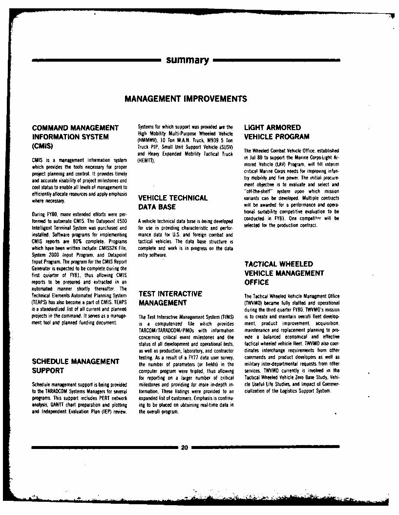
COMMAND MANAGEMENT Systems for which support was provided are the LIGHT ARMOREDINFORMATION SYSTEM High Mobility Multi-Purpose Wheeled Vehicle VEHICLE PROGRAM
(HMMWV), 10 Ton M.A.N. Truck, M939 5 Ton(CMIS) Truck PIP, Small Unit Support Vehicle (SUSV) The Wheeled Combat Vehicle Office, established
and Heavy Expanded Mobility Tactical Truckand Hs Expanded Mobilityn Tnformatao systm (in Jul 80 to support the Marine Corps-Light Ar-CMIS is a management information system (HEMTh. mored Vehicle (LAn) Program, will fill interimwhich provides the tools necessary for proper critical Marine C or weed f i v in fan-project planning and control. It provides timely ritiliy Corps needs for improving infan-and accurate visability of project milestones and try moblity and fire power. The initial procure-cost status to enable all levels of management to ment objective is to evaluate and select andefficiently allocate resources and apply emphasis 'off-the-shelf" system upon which misonwhere necessary. VEHICLE TECHNICAL variants can be developed. Multiple contracts
DATA BASE will be awarded for a performance and opera-
During FY80, many extended efforts were per- tional suitability competitive evaluation to be
formed to automate CMIS. The Datapoint 1500 A vehicle technical data base is being developed conducted in FY81. One competitnr will be
Intelligent Terminal System was purchased and for use in providing characteristic and perfor- selected for the production contract.
installed. Software programs for implementing mance data for U.S. and foreign combat andCMIS reports are 80% complete. Programs tactical vehicles. The data base structure iswhich have been written include: CMISS2K File, complete and work is in progress on the dataSystem 2000 Input Program, and Datapoint entry software.Input Program. The program for the CMIS Report TACTICAL WHEELEDGenerater is expected to be complete during thefirst quiarter of FY81, thus allowing CMIS VEHICLE MANAGEMENTreports to be prepared and extracted in an OFFICEautomated manner shortly thereafter. TheTechnical Elements Automated Planning System TEST INTERACTIVE The Tactical Wheeled Vehicle Managment Office(TEAPS) has also become a part of CMIS. TEAPS MANAGEMENT (IWVMO) became fully staffed and operationalis a standardized list of all current and planned during the third quarter FY80. TWVMO's missionprojects in the command. It serves as a manage- The Test Interactive Management System (TIMS) is to create and maintain overall fleet develop-ment tool and planned funding document. is a computerized file which provides ment, product improvement, acquisition,
TARCOM/TARADCOM/PMOs with information maintenance and replacement planning to pro-concerning critical event milestones and the vide a balanced economical and effectivestatus of all development and operational tests, tactical wheeled vehicle fleet. TWVMO also coor-as well as production, laboratory, and contractor dinates interchange requirements from othertesting. As a result of a FY77 data user survey, commands and product developers as well as
SCHEDULE MANAGEMENT the number of parameters (or fields) in the military inter-departmental requests from otherSUPPORT computer program were tripled, thus allowing services. TWVMO currently is involved in the
for reporting on a larger number of critical Tactical Wheeled Vehicle Zero Base Study, Vehi-Schedule management support is being provided milestones and providing for more in-depth in- cle Useful Life Studies, and Impact of Commer-to the TARADCOM Systems Managers for several formation. These listings were provided to an cialization of the Logistics Support System.programs. This support includes PERT network expanded list of customers. Emphasis is continu-analysis, GANTT chart preparation and plotting ing to be placed on obtaining real-time data inand Independent Evaluation Plan (IEP) review, the overall program.
20
summary
(DEA) Report, relating to the 16 DEAs under France, Germany, Israel, Italy, Egypt, EnglandINTERNATIONAL responsibility to TARADCOM TPOs was prepared and Australia under the ABCA Agreement. There
TECHNOLOGY EXCHANGE and forwarded to DARCOM. The report presents were seven visits by TPOs and ATPOs duringthe consolidated activity and status for each BEA FY80 to European countries to exchange intor-
The principal mechanism for technological com- during the past year (ending in July of each mation under the auspices of Data Exchangemunication within the NATO community for year). Agreements.tank-automotive equipment is the Combat andSupport Vehicles AC 225 Panel II. TARADCOM The International Technology Office (ITO) was in- Foreign contractors for whom visits were arrang-designated a Technical Director to monitor inter- volved in 31 visits involving 98 visitors from ed by the ITO represented companies ofnational activities with its International various foreign countries on briefings such as: England, Sweden, Israel, and Germany.Technology Exchange Function providing support lab test facilities, advanced concepts, researchto the NATO activity as well as to similar and engineering, TOW, HSTV, M60, XM1, ITO involvement in the information exchangeactivities under the Quadripartite Agreement, In- STE/ICE, quality assurance and the ROKIT pro- with foreign governments is expanding and it isternational Memoranda of Understanding & Data gram. These visits included notables from Korea, expected to result in an improved level of quali-Exchange Agreements, to exchange technical Japan, Israel, and several European countries. ty and standardization of US military equipmnent.data. A project which has been undertaken by the ITO
is investigation of candidates, domestic, andThe current strength of TACOM assigned ITO participates in equipment loans to foreign foreign for a new combat engineer vehicle. Thistechnical project officers (TPOs) is 16 and 27 countries. One such item was a M113A1 Carrier project was requested and funded by the Navy,assistant technical project officers (ATOPs). In Improved Cooling System Modification Kit, for the Marine Corps. It will take approximatelyFY80, they have maintained communication with which was loaned to Canada for testing. six months and will investigate vehicleforeign counterparts concerning TARADCOM characteristics to provide a comparison studyactivities. The Annual Data Exchange Agreement During the past year, TPOs and ATPOs visited from which a final condidate can be considered.
21
L
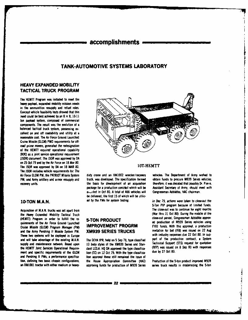
accomplishments
TANK-AUTOMOTIVE SYSTEMS LABORATORY
HEAVY EXPANDED MOBILITYTACTICAL TRUCK PROGRAM
The HEMTT Program was initiated to meet theheavy payload, expanded mobility mission needsin the ammunition resupply and refuel roles. 0Concept vehicle feasibility tests showed that thisneed could be best achieved by an 8 x 8, 10-11ton payload system, composed of commercialcomponents. The result was the evolution of abalanced tactical truck system, possessing ex-cellent on and off roadability and utility at areasonable cost. The Air Force Ground LaunchedCruise Missile (GLCM) PMO requirements for off-road prime movers, generated the redesignationof the HEMTT required operational capability(ROC) as a joint service operational requirement(JSOR) document The JSOR was approved by DAon 25 Oct 79 and by the Air Force on 18 Mar 80.The JSOR was approved by DA on 18 MAR 80. IOTHEMTTThe JSOR includes vehicle requirements for: TheAir Force GLCM PM, the PATRIOT Missile System duty crane and an XMI002 wrecker/recovery vehicles. The Department of Army wished toPM, and Army artillery and armor resupply and truck, was developed. The specification formed obtain funds to procure M939 Series vehicles;recovery units, the basis for development of an acquisition therefore, it was decided that possibly Dr. Pierre,
package for a production contrtct which will be Assistant Secretary of Army, should meet withah,(ded in Oct 80. A total of 466 vehicles will Congressman Addabbo, HAC chairman.be delivered, the first 15 of which will be utiliz-
10-TON M.A.N. ed by the PMs for system testing. in Dec 79, actions were taken to close-out the5-Ton PIP program because of limited funds.
Acquisition of M.A.N. trucks was set apart from The close-out was to continue for eight monthsthe Heavy Expanded Mobility Tactical Truck (Mar thru 31 Oct 80). During the middle of the(HEMTI) Program in order to fulfill the re- 5-TON PRODUCT close-out period, Congressman Addabbo approv-quirements of the Air Force Ground Launched ed production of M939 Series vehicles usingCruise Missile (GLCM) Program Manager (PM) IMPROVEMENT PROGRM FY81 funds. With this approval, a productionand the Army Pershing II Missile System PM. XM939 SERIES TRUCKS invitation for bid (IFB) was issued on 22 AugThese two systems will be deployed in Europe with industry responses due 22 Oct 80. In sup-and will take advantage of the existing M.A.N. The DEVA IPR, held on 5 Sep 79, type classified port of the production contract, a Systemsupply and maintenance network. Based upon 13 body styles of the XM939 Series and Stan- Technical Support (STS) request for quotationthe HEMTT Joint Services Operational Require- dard LCC-A. HQ DA approved the type classifice- (RFP) was issued on 8 Sep 80 with responsesment and specific requirements of the GLCM tion (TC) on 12 Oct 79. With the type classifica- due by 27 Oct 80.and Pershing If PMs, a performance specifica- tion approval these still remained the issue oftion, defining two basic chassis configurations, the House Appropriation Committee (HAC) Production of the 5-ton product improved M939an XMI0 tractor with either medium or heavy- approving funds for production of M939 Series series truck results in modernizing the 5-ton
22
LJ~n"21A
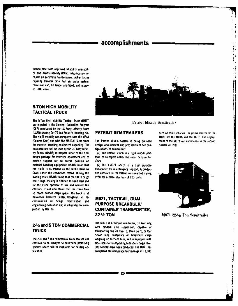
accomplishments
tactical fleet with improved reliability, availabili-ty, and maintainability (RAM). Modification in-cludes an automatic transmission, higher torquecapacity transfer case, full air brake system,three man cab, tilt fender and hood, and improv-ed fifth wheel.
5-TON HIGH MOBILITYTACTICAL TRUCK
The 5-Ton High Mobility Tactical Truck (HMTT) Patriot Missile Semitrailerparticipated in the Concept Evaluation Program
(CEP) conducted by the US Army Infantry Board(USAIB) during Oct 79-Jan 80 at Ft. Benning, GA. PATRIOT SEMITRAILERS each on three vehicles. The prime movers for theThe HMTT mobility was compared with the M561 M871 are the M818 and the M915. The deploy-(Gamma Goat) and with the M813A1 5-ton truck The Patriot Missile System is being provided ment of the M871 will commence in the secondfor materiel handling equipment capability. The design, development and production of two con- quarter of FY81.data obtained will be used by the US Army Infan- figurations of semitrailers:try School (USAIS) to prepare input to the final (1) The XM860 which is a rigid mobile plat-design package for interface equipment and to form to transport either the radar or launcherprovide support for an overall position on units.materiel handling equipment. USAIB found that (2) The XM974 which is a dual purposethe HMTT is as mobile as the M561 (Gamma transporter for maintenance support. A produc-Goat) under the conditions tested. During the tion contract for the XM860 was awarded duringloading trials, USAIB found that the HMTT cargo FY80 for a three year buy of 203 units.bed is high, making it difficult to hand load andfor the crane operator to see and operate thecontrols. It was also found that the crane tookup much needed cargo space. The truck is atKeweenaw Research Center, Houghton, MI, for M871, TACTICAL, DUALcontinuation of design modification andengineering evaluation and is scheduled for com- PURPOSE BREAKBULK/pletion by Dec 80. CONTAINER TRANSPORTER,
22-1/2 TON M871 22-1/2 Ton Semitrailer
The M871 is a flatbed semitrailer, 30 feet long2- and 5 TON COMMERCIAL with tandem axle suspension, capable ofTRUCK transporting one 20, two 10, three 6-2/3, or four
5-foot long containers or breakbulk cargoThe 2-% and 5 ton commercial truck market will weighing up to 22-4 tons, and is equipped withcontinue to be surveyed to determine promising side racks for transporting breakbulk cargo. Oversystems which will be evaluated for military ap- 300 vehicles have been produced. The M871 hasplication. completed the endurance test mileage of 12,000
23
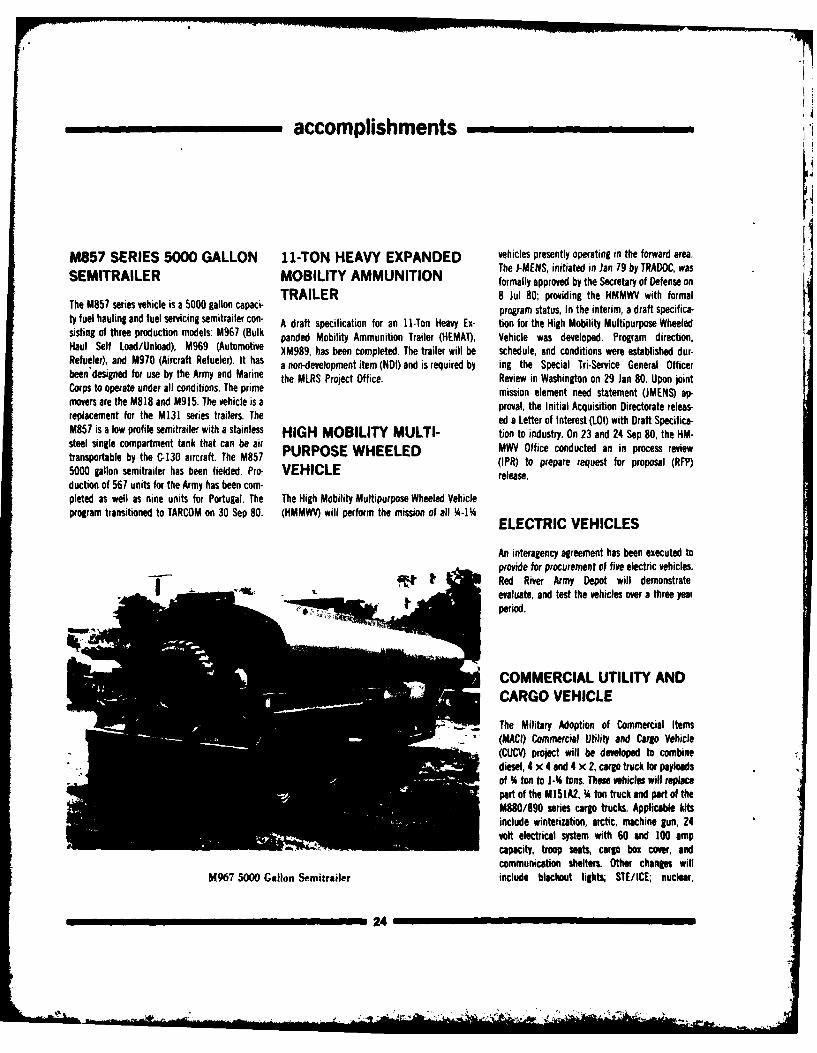
accomplishments
M857 SERIES 5000 GALLON 11-TON HEAVY EXPANDED vehicles presently operating in the forward area.The J-MENS, initiated in Jan 79 by TRADOC, was
SEMITRAILER MOBILITY AMMUNITION formally approved by the Secretary of Defense onTRAILER 8 Jul 80; providing the HMMWV with formal
The M857 series vehicle is a 5000 gallon capaci program status, In the interim, a draft specifica-ty fuel hauling and fuel servicing semitrailer con- A draft specification for an 11-Ton Heavy Ex- tion for the High Mobility Multipurpose Wheeledsisting of three production models: M967 (Bulk panded Mobility Ammunition Trailer (HEMAl), Vehicle was developed. Program direction,Haul Self Load/Unload), M969 (Automotive XM989, has been completed. The trailer will be schedule, and conditions were established dur-Refueler), and M970 (Aircraft Refueler). It has a non-development item (NDI) and is required by ing the Special Tri-Service General Officerbeen designed for use by the Army and Marine the MLRS Project Office. Review in Washington on 29 Jan 80. Upon jointCorps to operate under all conditions. The prime mission element need statement (JMENS) ap-movers are the M818 and M915. The vehicle is a proval, the Initial Acquisition Directorate releas-replacement for the M131 series trailers. The ed a Letter of Interest (LOI) with Draft Specifica-M857 is a low profile semitrailer with a stainless HIGH MOBILITY MULTI- tion to industry. On 23 and 24 Sep 80, the HM-steel single compartment tank that can be aitransportable by the C-n30 aircraft. The M857 PURPOSE WHEELED MWV Office conducted an in process review
(IPR) to prepare request for proposal (RFP)5000 gallon semitrailer has been fielded. Pro- VEHICLE release.duction of 561 units for the Army has been com-pleted as well as nine units for Portugal. The The High Mobility Multipurpose Wheeled Vehicleprogram transitioned to TARCOM on 30 Sep 80. (HMMWV) will perform the mission of all -IC ELECTRIC VEHICLES
An interagency agreement has been executed toprovide for procurement of five electric vehicles.
It' Red River Army Depot will demonstrateevaluate, and test the vehicles over a three yearperiod.
COMMERCIAL UTILITY ANDCARGO VEHICLE
- The Military Adoption of Commercial Items
(MACl) Commercial Utility and Carlo Vehicle(CUCV) project will be developed to combinediesel, 4 x 4 and 4 x 2, cargo truck for payloadsof % ton to 1- tons. These vehicles will replacepart of the M15lA2, % ton truck and part of theM880/890 series cargo trucks. Applicable kits
include winterization, arctic, machine gun, 24volt electrical system with 60 and 100 ampcapacity, troop seats, cargo box cover, andcommunication shelter%. Other changes will
M967 5000 Gallon Semitrailer include blackout lights; STE/ICE; nuclear,
24
4i.- mar_'-
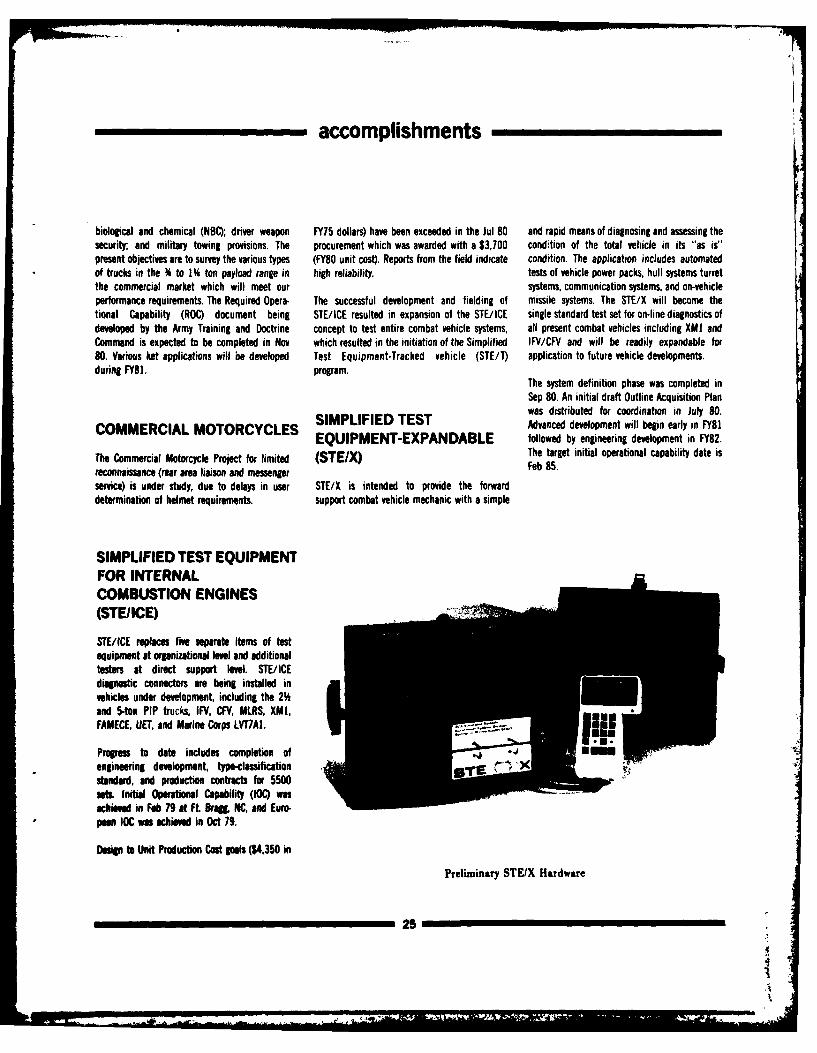
accomplishments
biological and chemical (NBC); driver weapon FY75 dollars) have been exceeded in the Jul 80 and rapid means of diagnosing and assessing thesecurity and military towing provisions. The procurement which was awarded with a $3,700 condition of the total vehicle in its "as is"present objectives are to survey the various types (FY80 unit cost). Reports from the field indicate condition. The application includes automatedof trucks in the % to 1 ton payload range in high reliability, tests of vehicle power packs, hull systems turretthe commercial market which will meet our systems, communication systems, and on-vehicleperformance requirements. The Required Opera- The successful development and fielding of missile systems. The STE/X will become thetional Capability (ROC) document being STE/ICE resulted in expansion of the STE/ICE single standard test set for on-line diagnostics ofdeveloped by the Army Training and Doctrine concept to test entire combat vehicle systems, all present combat vehicles including XMI andCommand is expected to be completed in Nov which resulted in the initiation of the Simplified IFV/CFV and will be readily expandable for80. Various ket applications will be developed Test Equipment-Tracked vehicle (STE/T) application to future vehicle developments.during FY81. program.
The system definition phase was completed inSep 80. An initial draft Outline Acquisition Plan
was distributed for coordination in July 80.
COMMERCIAL MOTORCYCLES TEST Advanced development will begin early in FY81EQUIPMENT-EXPANDABLE followed by engineering development in FY82.
The Commercial Motorcycle Project for limited (STEM) The target initial operational capability date is
reconnaissance (rear area liaison and messenger Feb 85.
service) is under study, due to delays in user STE/X is intended to provide the forwarddetermination of helmet requirements. support combat vehicle mechanic with a simple
SIMPLIFIED TEST EQUIPMENTFOR INTERNAL
COMBUSTION ENGINES(STE/ICE)
STE/ICE replaces five separate items of testequipment at organizational level and additionaltesters at direct support levl. STE/ICEdiagnostic connectors are being installed invehicles under development, including the 2'hand 5-ton PIP trucks, IFV, CFV, MLRS, XMI,FAMECE, UET, and Marine Corps LVT7AI.
Progress to date includes completion ofengineering development, type-classificationstandard, and production contracts for 5500sets. Initial Operational Capability (IOC) wasachieved in Feb 79 at Ft 8raL NC, and Euro-pan IOC was achieved in Oct 79.
Design to Unit Production Cost goals ($4,350 in
Preliminary STEIX Hardware
25
-,
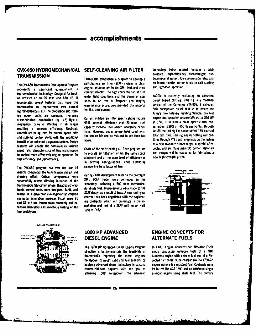
accomplishments
CVX-6SO HYDROMECHANICAL SELF-CLEANING AIR FILTER technology being applied includes a high
TRANSMISSION pressure, high-efficiency turbocharger; tur-TARADCOM established a program to develop a bocompound system; low-compression ratio, and
The CVX-150 Transmission Development Program self-cleaning air filter (SCAF) system to clean an intake manifol burner to aid in cold starting
represents a significant advancement in engine induction air for the XMI tank and other and light-load operation.
hydromechanical technology. Designed for track- combat vehicles. The high concentration of dust
ed vehicles up to 25 tons and 650 HP, it under field conditions and the desire of user TACOM is currently evaluating an advanced
incorporates several features that make this units to be free of frequent and lengthy diesel engine test rig. This rig is a modified
transmission an improvement over current maintenance procedures provided the impetus version of the Cummins VTA-903, 8 cylinder,
hydromechanicals. (1) The propulsion and steer- for this development. 500 horsepower diesel that is to power the
ing power paths are separate, improving Army's new Infantry Fighting Vehicle. the test
transmission controllability. (2) Hydro- Current military air filter specifications require engine has operated successfully up to 850 HP
mechanical drive is effective in all ranges 99.5 percent efficiency and 20-hours dust at 3200 RPM with a brake specific fuel con-
resulting in increased efficiency. Electronic capacity (service life) under laboratory condi- sumption (BSFC) of .400 lb per hp/hr. Through
controls are being used for precise speed ratio tions. However, under severe field conditions, Jul 80 the test rig has accumulated 145 hours of
and steering control along with the additional the service life can be reduced to less than two total test time. Test rig engine testing will con-
benefit of an inherent diagnostic system. Design hours. tinue through FY81 with emphasis on the testing
features will enable the continuously variable of a new advanced turbocharger, a special after-
speed ratio characteristics of this transmission Goals of the self-cleaning air filter program are cooler, and an intake manifold burner. Materials
to control more effectively engine operation for to provide air filtration within the same space and designs will be evaluated for fabricating a
fuel efficiency and performance. allotment and at the same level of efficiency as new high-strength piston.in existing configurations, while extending
The CVX-650 program has over the last 15 service life by a factor of five.months completed the transmission design anddrawing effort. Critical components were During FY80, development tests on the prototype
successfully tested allowing initiation of the XMI SCAF model were continued in the
transmission fabrication phase. Breadboard elec- laboratory, including a 500 hour mechanical
tonic control units were designed, built, and durability test. Improvements were made to the
tested in a driw/vehicle/engine/transmission SCAF design as a result of tests. A new multi-year
computer simulation program. Fiscal years 81 contract has been negotiated with the engineer-
and 82 will see transmission assembly and ex- ing contractor which will culminate in the in-
tensive laboratory and in-vehicle testing of the stallation and test of a SCAF unit on an XM1t pas. ank in FY82.
CVX-6SO TRANSAM8ION
1000 HP ADVANCED ENGINE CONCEPTS FORDIESEL ENGINE ALTERNATE FUELS
The 1000 HP Advanced Diesel Engine Program In FY80, Engine Concepts for Alternate Fuelsobiective is to demonstrate the feasibility of group conducted in-house tests of a NTCdramatically improving the diesel engines' Cummins engine with a shale fuel and of a Air-horsepower to weight ratio and fuel economy by cooled "Y" Diesel Supercharged (AVDS) 1 790-2c
" "applying advanced diesel technology to existing engine using a fire resistant fuel. Contracts werecommercial-base engines, with the goal of let to test the AGT 1500 and an adiabatic singleachieving 1000 horsepower. The advanced cylinder engine using shale fuel. The primary
26
. ... r
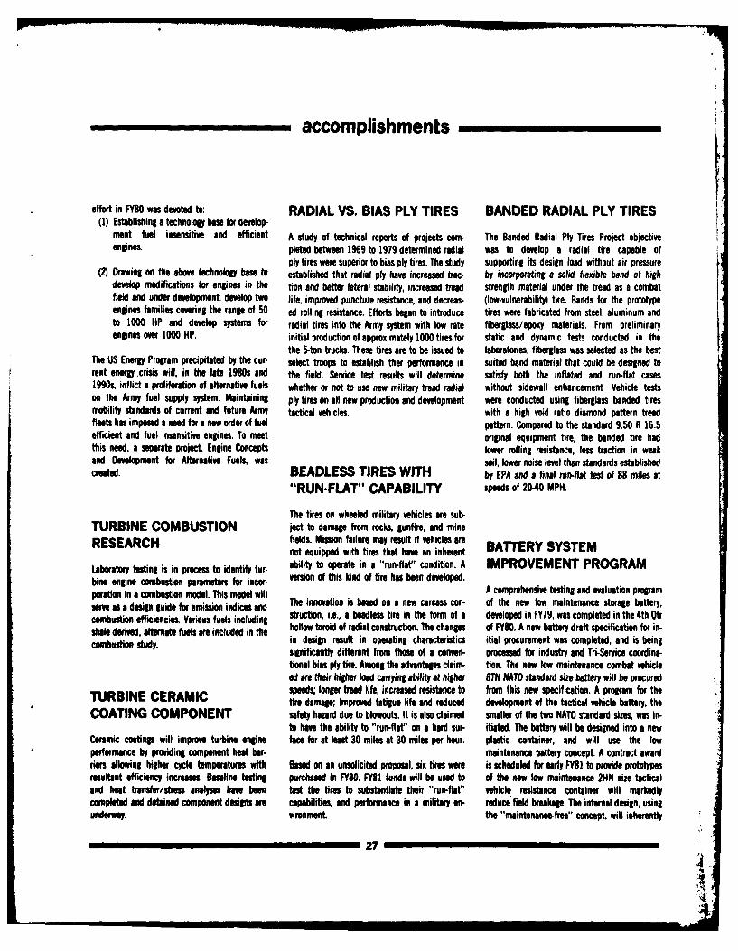
accomplishments_
effort in FY80 was devoted to: RADIAL VS. BIAS PLY TIRES BANDED RADIAL PLY TIRES(1) Establishing a technology base for develop-
ment fuel insensitive and efficient A study of technical reports of projects corn- The Banded Radial Ply Tires Project objectiveengines. pleted between 1969 to 1979 determined radial was to develop a radial tire capable of
ply tires were superior to bias ply tires. The study supporting its design load without air pressure(2) Drawing on the above technology base to established that radial ply have increased trac- by incorporating a solid flexible band of high
develop modifications for engines in the tion and better lateral stability, increased tread strength material under the tread as a combatfield and under development, develop two life, improved puncture resistance, and decreas- (low-vulnerability) tire. Bands for the prototypeengines families covering the range of 50 ad rolling resistance. Efforts began to introduce tires were fabricated from steel, aluminum andto 1000 HP and develop systems for radial tires into the Army system with low rate fiberglass/epoxy materials. From preliminaryengines over 1000 HP. initial production of approximately 1000 tires for static and dynamic tests conducted in the
the 5-ton trucks. These tires are to be issued to laboratories, fiberglass was selected as the bestThe US Energy Program precipitated by the cur- select troops to establish ther performance in suited band material that could be designed torent energy.crisis will, in the late 1980s and the field. Service test results will determine satisfy both the inflated and run-flat cases1990s, inflict a proliferation of alternative fuels whether or not to use new military tread radial without sidewall enhancement Vehicle testson the Army fuel supply system. Maintaining ply tires on all new production and development were conducted using fiberglass banded tiresmobility standards of current and future Army tactical vehicles, with a high void ratio diamond pattern treadfleets has imposed a need for a new order of fuel pattern. Compared to the standard 9.50 R 16.5efficient and fuel insensitive engines. To meet original equipment tire, the banded tire hadthis need, a separate project, Engine Concepts lower rolling resistance, less traction in weakand Development for Alternative Fuels, was sil, lower noise level then standards establishedcreated. BEADLESS TIRES WITH by EPA and a final run-flat test of 88 miles at
"RUN-FLAT" CAPABILITY speeds of 20-40 MPH.
The tires on wheeled military vehicles are sub-TURBINE COMBUSTION ject to damage from rocks, gunfire, and mineRESEARCH fields. Mission failure may result if vehicles are
not equipped with tires that have an inherent BATFERY SYSTEMLaboratory testing is in process to identify tur- ability to operate in a "run-flat" condition. A IMPROVEMENT PROGRAMbine engine combustion parameters for incor- version of this kind of tire has been developed.poration in a combustion model. This model will A comprehensive testing and evaluation programer as a design guide for emission indices and The innovation is based on a new carcass con- of the new low maintenance storage battery,combustion efficiencies Various fuels including struction, i.e., a heedless tire in the form of a developed in FY79, was completed in the 4th Qtr
scobe dtived, alternate fuels ae included in the hollow tori of radial construction. The changes of FY80. A new battery draft specification for in-combustion study in design result in operating characteristics itial procurement was completed, and is being
significantly different from those of a conven- processed for industry and Tri-Service coordina-
tional bias ply tire. Among the advantages claim- tion. The new low maintenance combat vehicleed are their higher lod carrying ability at higher 6TN NATO standard size battery will be procured
TURBINE CERAMIC speeds; longer tread life; increased resistance to from this new specification. A program for thetire damage; improved fatigue life and reduced development of the tactical vehicle battery, the
COATING COMPONENT safety hazard due to blowouts. It is also claimed smaller of the two NATO standard sizes, was in-to have the ability to "run-flat" on a hard sur- itiated. The battery will be designed into a new
Ceramic coatings will improve turbine engine face for at least 30 miles at 30 miles per hour. plastic container, and will use the lowperformance by providing component heat bar- maintenance battery concept. A contract awardriers allowing higher cycle temperatures with Based on an unsolicited proposal, six fires were is scheduled for early FY8 I to provide prototypesresultant efficiency increases. Baseline testing purchased in FY80. FY81 funds will be used to of the new low maintenance 2HN size tacticaland heat trnsfer/stress analyses have been test the tires to substantiate their "run-flat" vehicle resistance container will markedlycompleted and detained component designs are capabilities, and performance in a military en- reduce field breakage. The internal design, usingunderway. vironment. the "maintenance-free" concept, will inherently
27
IIIIIIIIIIIIM
accomplishments
provide capabilities and characteristics for long that the future procurement of the 12-volt inter- SELF-FORMING GASKETterm "wet" storage life, reducing failures due to vehicle slave cable kit will be manufactured tosulfation and virtuaJly eliminating failures in the the new military standard and specification. MATERIALfield fue to overcharging.
The Self-Forming Gasket Material Program wasto utilize commercially available self-curingplastic material to form in-place-gaskets (FIPG)
SINGLE LEVER LIGHT as a replacement for preformed cork, paper, and12/24 VOLT CONVERTER SWITCH rubber gaskets in military vehicle. A thin bead of
paste-consistency, room-temperature vulcanizedA 12/24 volt conversion unit for providing 24 The Single Lever Light Switch Project objective is (RTV) silicone flows between them, filling allvolt power on commercial vehicles procured by to provide a new easily operated military light voids and irregularities. The gasket cures inthe military is being tested. switch with a simple design. The present three- presence of moisture to a solid silicone rubber
lever military switch is difficult to operate. The gasket that has excellent flexibility, thermalThe proposed converter will supplant the current new single lever switch will provide infinite pilot stability, and fluid resistance.procedure of adding a complete new 24 volt lamp dimming, a requirement of the Nationalsystem to each vehicle, complete with two Highway Safety Standard. The new switch is in- Field test results, using tactical vehicle com-12-volt batteries, a 24-volt regulator, and a terchangeable with the current three-lever ponents at Tooele Army Depot, Utah, proved that24-volt alternator with drive pulley and belts. military switch. Fifteen switches have been the RTV is recommended for (1) makingThe converter is to be employed for operating fabricated and four switches are undergoing emergency repairs, (2) as a substitute for anyradio sets, gun firing solenoids, rotating warning laboratory tests. An extensive field-test program non-shimmering or non-metallic gaskets notbeacons, and other lights and devices currently on vehicles at Ft. Knox is planned. Project com- used in the exhaust system or in direct contactpowered by 24-volt military vehicle electrical pletion is scheduled for 1st Qtr FY81. with liquid fuel, and (3) use in conjunction withsystems. The new system has been installed on gaskets to help seal troublesome areas.five vehicles at Ft. Lewis, Washington, and onevehicle at TARADCOM with successful results todate. ROTATIONAL MOLDED
POLYETHYLENE FUEL VEHICLE NOISE REDUCTIONTANKS
During FY80, a noise measurement and reduc-12-VOLT INTER-VEHICLE Manufacturing technology revealed rotational tion test facility, has been completed to enableSLAVE CABLE KIT molded cross-linkable high density polyethylene TACOM vehicles to meet MIL-STD-1474B. A semi-
plastic exhibited the desirable chemical and anechoic chamber has been equipped withThe 12-Volt Inter-Vehicle Slave Cable Kit Project physical properties for the fabrication of large acoustic instrumentation and a roadwheelobjective was to proie 12-volt military tactical capacity fuel tanks for the M551 Vehicle. dynamometer. The vehicle test room has a steelvehicles with a convenient, practical, and safe reinforced concrete floor, intake and exhaustmethod for starting a disabled vehicle of the A contract is being negotiated for the tooling of a blowers, a roof that can be raised, and a controlsame type 12-volt electrical system. The kit con- permanent cast aluminum molt for the 5-Ton room. The acoustic wedges in the chamber aressts of an external vehicle receptacle and an cargo truck fuel tank. The mold is to be shot 26 in. long and have a 200Hz cut-off frequencyinter-vehicle cable with mating connectors. The peen textured, incorporating the necessary ribs below which they are less than 97 percent ab-receptacle and connectors are of a design that (fillets) and corner radii, to maintain fuel tank sorptive. A test vehicle can be subjected to everyprecludes the use on 24-volt vehicles. Sample shape installed, including fuel weight and driving condition from idle to full throttle atkits have been successfully tested at Yuma Prov- sidewall effects. Fuel tanks will then be sub- speeds up to 70 mph. An accompanying controling Grounds and the Cold Regions Test Center. jected to durability testing. Results can then be console displays road speed and roadInput data for incorporation into both the obtained as to the fielding of rotational molded horsepower. A strip-chart recorded can be usedmilitary standard (MS) and the military specifica- cross-linkable high-density polyethylene fuel as a driving-aid. The procedure for baseline noisetion was prepared. The documentation assures tanks. testing has been developed.
28
- a ~ - - ,-, .,. ... . A
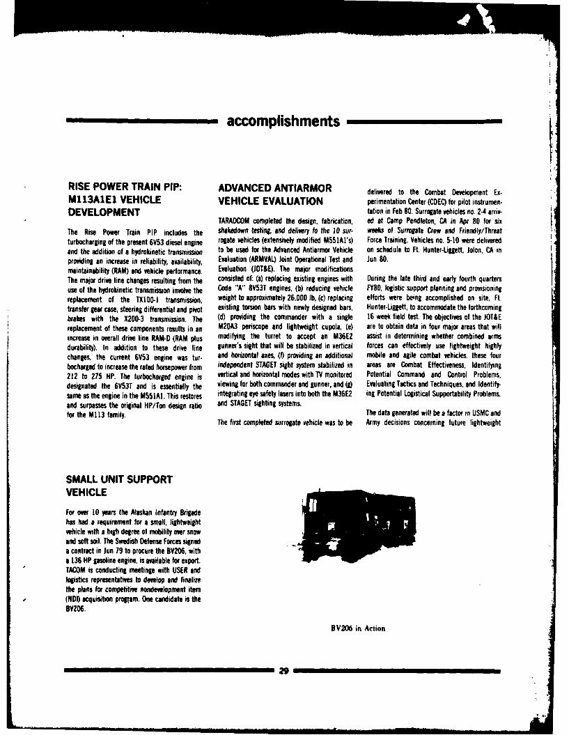
accomplishments _
RISE POWER TRAIN PIP: ADVANCED ANTIARMOR delivered to the Combat Development Ex-M113A1E1 VEHICLE VEHICLE EVALUATION perimentation Center (CDEC) for pilot instrumen-DEVELOPMENT tation in Feb 80. Surrogate vehicles no. 2-4 ariv-
TARADCOM completed the design, fabrication, ed at Camp Pendleton, CA in Apr 80 for sixThe Rise Power Train PIP includes the shakedown testing, and delivery 1o the 10 sur- weeks of Surrogate Crew and Friendly/Threatturbocharging of the present 6V53 diesel engine rogate vehicles (extensively modified M551AI's) Force Training. Vehicles no. 5-10 were deliveredand the addition of a hydrokinetic transmission to be used for the Advanced Antiarmor Vehicle on schedule to Ft. Hunter-Liggett, Jolon, CA inproviding an increase in reliability, availability, Evaluation (ARMVAL) Joint Operational Test and Jun 80.maintainability (RAM) and vehicle performance. Evaluation (JOT&E). The major modificationsThe major drive line changes resulting from the consisted of: (a) replacing existing engines with During the late third and early fourth quartersuse of the hydrokinetic transmission involve the Code "A" 8V53T engines, (b) reducing vehicle FY80, logistic support planning and provisioningreplacement of the TX100-1 transmission, weight to approximately 26,000 lb, (c) replacing efforts were being accomplished on site, Ft.transfer gear case, steering differential and pivot existing torsion bars with newly designed bars, Hunter-Liggett, to accommodate the forthcomingbrakes with the X200-3 transmission. The (d) providing the commander with a single 16 week field test. The objectives of the JOT&Ereplacement of these components results in an M20A3 periscope and lightweight cupola, (e) are to obtain data in four major areas that willincrease in overall drive line RAM-D (RAM plus modifying the turret to accept an M36E2 assist in determining whether combined armsdurability). In addition to these drive line gunner's sight that will be stabilized in vertical forces can effectively use lightweight highlychanges, the current 6V53 engine was tur- and horizontal axes, (1) providing an additional mobile and agile combat vehicles, these fourbocharged to increase the rated horsepower from independent STAGET sight system stabilized in areas are Combat Effectiveness, Identifying212 to 275 HP. The turbocharged engine is vertical and horizontal modes with TV monitored Potential Command and Control Problems,designated the 6V53T and is essentially the viewing for both commander and gunner, and (g) Evaluating Tactics and Techniques, and Identify-same as the engine in the M551A1. This restores integrating eye safety lasers into both the M36E2 ing Potential Logistical Supportability Problems.and surpasses the original HP/Ton design ratio and STAGET sighting systems.for the M113 family. The data generated will be a factor in USMC and
The first completed surrogate vehicle was to be Army decisions concerning future lightweight
SMALL UNIT SUPPORTVEHICLE
For over 10 years the Alaskan Infantry Brigadehas had a requirement for a small, lightweightvehicle with a high degree of mobility over snowand soft soil. The Swedish Defense Forces signeda contract in Jun 79 to procure the BV206, witha 136 HP gasoline engine, is available for export.TACOM is conducting meetinge with USER andlogistics representatives to develop and finalizethe plans for competitive nondevelopment item(NDI) acquisition progtam. One candidate is theBV206.
BV206 in Action
29
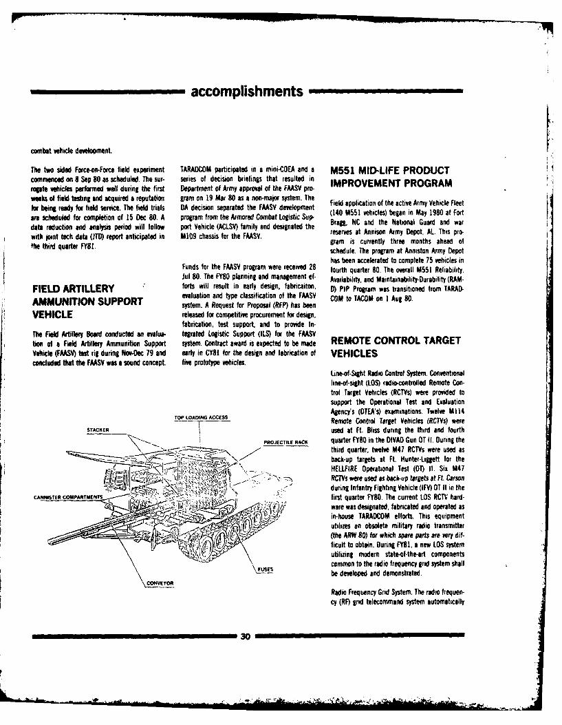
accomplishments
combat vehicle development.
The two sided Force-on-Force field experiment TARADCOM participated in a mini-COEA and a M551 MID-LIFE PRODUCTcommenced on 8 Sep 80 as scheduled. The sur- series of decision briefings that resulted in IMPROVEMENT PROGRAMrogate vehicles performed well during the first Department of Army approval of the FAASV pro.
weeks of field testing and acquired a reputation gram on 19 Mar 80 as a non-major system. The Field application of the active Army Vehicle Fleetfor being ready for field service. The field trials DA decision separated the FAASV development (140 M551 vehicles) began in May 1980 at Fortare scheduled for completion of 15 Dec 80. A program from the Armored Combat Logistic Sup-data reduction and analysis period will follow port Vehicle (ACLSV) family and designated the Brag, NC and the National GuarD and warwith joint tech data (JTD) report anticipated in M109 chassis for the FAASV. reserves at Annison Army Depot, AL This pro-thegram is currently three months ahead ofschedule. The program at Anniston Army Depot
has been accelerated to complete 75 vehicles inFunds for the FAASV program were received 28 fourth quarter 80. The overall M551 Reliability,Jul 80. The FY80 planning and management ef- Availability, and Maintainability-Durability (RAM-
FIELD ARTILLERY forts will result in early design, fabricaiton, D) PIP Program was transitioned from TARAD-evaluation and type classification of the FAASV COM to TACOM on 1 Aug 80.
AMMUNITION SUPPORT system. A Request for Proposal (RFP) has been
VEHICLE released for competitive procurement for design,fabrication, test support, and to provide In-
The Field Artillery Board conducted an evalua- tegrated Logistic Support (ILS) for the FAASVtion of a Field Artillery Ammunition Support system. Contract award is expected to be made REMOTE CONTROL TARGETVehicle (FAASV) test rig during Nov-Dec 79 and early in CY81 for the design and fabrication of VEHICLESconcluded that the FAASV was a sound concept. five prototype vehicles.
Line-of-Sight Radio Control System. Conventionalline-of-sight (LOS) radio-controlled Remote Con-trol Target Vehicles (RCTVs) were provided tosupport the Operational Test and EvaluationAgency's (OTEA's) examinations. Twelve M114
TOP LOADING ACCESS Remote Control Target Vehicles (RCTVs) wereSTACKER Ci used at Ft. Bliss during the third and fourth
PROJECTILE RACK quarter FY80 in the DIVAD Gun OT II. During theSTACKd qua80r twelve M47 RCTVs were used as
back-up targets at Ft. Hunter-Liggett for thee- -I' .- i 7 ,-i- \ HELLFIRE Operational Test (O) II. Six M47
Z** 77, RCTVs were used as back-up targets at Fl. CarsonC S CP-S - >during Infantry Fighting Vehicle (IFV) OT II in the
cANNsTER COMPARTMENTS. first quarter FY80. The current LOS RCTV hard-"ware was designated, fabricated and operated as
in-house TARADCOM efforts. This equipment.. > utilizes an obsolete military radio transmitter
T. (the ARW 80) for which spare parts are very di,-ficult to obtain. During FY81, a new LOS systemutilizing modern state-of-the-art components
common to the radio frequency grid system shallFUSES be developed and demonstrated.
CONV1EYOR
Radio Frequency Grid System. The radio frequen-cy (RF) grid telecommand system automatically
30
__, .. ... ... .. .................. .. .--.------ ,----,------,------,--.---.--•-,---------,--------- . , .. , , .
accomplishments
controls multiple threat vehicles over uneven ter- FIRE CONTROL SYSTEMS ARMY FIRE CONTROLrain for both testing and training. The system is INTEGRATION PLANNING GUIDE SUPPORTbased on three transportable radio transmitterswhich generate a local hyperbolic grid, and the TARADCOM's fire control systems objective is to TARADCOM assisted ARRADCOM during FY80 invehicle mounted receiver microcomputer andsrvmechanismswhich reie m pther ad coordinate and integrate fire control updating the Army Fire Control Science andservomechanisms which guide the target vehicle developments by various DARCOM Commands Technology Base Planning Guide. FY81 activitieshabyemoe preracmesingpay abtraryicse whih and organizations to assure that new will continue to inject detailed combat vehiclehas been programmed simply by driving the vehi-cle. Advantages include non-line-of-sight, day technologies progress toward fielding in an oriented fire control programs, highlighted in the
and night, and multiple vehicle operations using orderly manner. time-phased with related com- fire control planning guide.bat vehicle systems. TARADCOM funded selectedtechnologies and system developments in FY80
infulfillment of their objective to coordinate andTwelve advanced developm ent prototype M 47 in e r t f re c t ol d v op n s. D i gtank RCTVs were completed and underwent the integrate fire control developments. During TURRET AND WEAPONbapismof ivefir duin th HELFIE O IIin FY80, TARADCOM continued to provide supportbaptism of live fire during the HELLFIRE OT 11 in to the Human Engineering Laboratory for SYSTEM INTEGRATIONthe third quarter FY80. development of the Fire Control Research System
test bed which will provide for data collection The turret and weapon station integration in-
associated with the man/machine interfaces of volves several tasks which will result in advancedMANNED EVASIVE TARGET tank fire control systems. systems and techniques for TARADCOM to utilize
in its role as systems integrator of total combat
TANK vehicles. The objective of this task is the coor-The initial effort of the study entitled "Fire Con- dination of development efforts leading to the
Three Manned Evasive Target Tanks (MET1) have trol Concepts for Maneuvering Targets" was com- integration of technology within the turret underbeen fabricated by TARADCOM for the Opera- pleted during FY80. The first phase of this the constraints of technology, cost, weight,tional Test and Evaluation Agency (OTEA) to pro- analytical effort produced fire control system space, human factors, complexity, and perfor-vide realistic combat vehicle targets for anti- models and analytical techniques for evaluating mance. During FY80, several activities werearmor missile testing. During FY80 several the performance of tank fire control systems. undertaked concurrently.modifications were installed into the METT During FY81, a maneuvering target modelvehicles to prevent entry of small airborne metal developed by AMSAA will be validated using field Position Control System. The Position Controland dust particles. The particles entered the test data and an appropriate analytical model of System activity was initiated to evaluate positioncrew compartment through the ventilation the human gunner will be developed. The vs. rate inputs to the turret/weapon drive systemsystem and around periscopes during tests developed models will be used to compare both and the potential enhancement of target track-where inert TOW missles were fired against it. analytically and by simulation selected fire con- ing capabilities against evasive targets. APlanned activities for FY81 call for testing to trol configurations in order to furnish specific displacement sensitive trackball control systemqualify the MElT against subcaliber inert VIPER guidance for future fire control system develop- was built and testing and evaluation were in-missiles at very close ranges. ment. itiated. During FY80, testing included evaluation
on the Human Engineering Laboratory (HEL)tracking simulator and in a vehicle installation in
The maneuvering target test of the GM version the ARRADCOM M60 test bed. Tests indicate aXM 1 fire control system was not able to be con- potential improvement in operator performance
FMS TECHNICAL SUPPORT ducted as originally planned. TARADCOM and the need for further testing. Activities were
ACTIVITIES assisted ARRADCOM during FY80 in updating extended to include a coordinated TARADCOM-the Army Fire Control Science and Technology HEL PCS evaluation of the TARADCOM dynamic
TARADCOM provided automotive support to two Base Planning Guide. FY81 activities will con- ride simulator.teams which conducted surveys in Egypt to tinue to inject detailed combat vheicle orienteddetermine what technical assistance could be fire control programs, highlighted in the fire con- Fluidic Tank Turret Stabilization. The fluidicprovided to keep certain combat vehicles opera- trol planning guide, into the combat vehicle stabilization study objectives in FY80 were totional in future years. science and technology base. assess performance trade offs between various
31
accomplishments
hybrid turret stabilization systems in terms of GUN TUBE BENDING Fuel Lines Program objective is to prove thethe XM-1 performance requirements. The study ANALYSIS feasibility of a passive fire suppression systemconcluded that development of a pheumatic gyro for hydraulic and fuel lines. Unprotected linesreplacement rate sensor for application in a Ft80 Gun Tube Bending Analysis included are vulnerable to rupture and ignition resultinghybrid pheumatic/electronic system would be in an explosive fire. Lines are hazardous whenthe most readily implemented improvement for publication of a final report highlighting ap- located outside the view of optical fire sensors.the m-yst pem e ipreciable errors induced by gun tube bending as This system will provide fire suppressantthe XM-] system. a function of mobility and vehicle transmitter Tacseingt hichiwhep ruv uredf wil supp lys a
terrain inputs. Reduced FY80 funding prohibits jacketing which, when ruptured r will supply a
As a result of the fluidic stabilization feasibility the extension of simlar simulation activities, cuppressant cloud (probably a dry powder
study, development of a pheumatic gyro rate chemical agent suspended in a thixogelled
sensor, to replace the current XM-1 gyro, has HALON) precisely at a point of the rupture. Our-
been undertaken and will be completed during ing FY80 a contract was awarded for the designFY83. The hybrid pheumatic/electronic system and fabrication of experimental hardware. Dur-is e Ted toyrvidevitalata tec proe sste ing FY81, a realistic test procedure and base lineis expected to provide vital data t an tohe FIRE SURVIVABILITY threat data will be developed with actual evalua-concept of a direct gy~ro replacement and to
document the improvement in maintaining ac- SYSTEM INTEGRATION tion of the passive suppression system scheduled
curacy on target while the vehicle is on the for mid-FY82.
move. The Fire Survivability System Integration Pro-gram objectives are to coordinate all DARCOM
A concept study for specific applications of an programs related to fire survivability and to in-
all pneumatic stabilization system for the XM-1 itiate new technologies that enhance vehicel fire
has been initiated with a scheduled completion survivability. The Mobility Equipment Research GAS-LIQUID DYNWMICSdate of Feb 81. In conjunction with the and Development Command (MERADCOM) has
analytical comparison between the hybrid and modified two fire extinguisher recharge sets to The Gas-Liquid Dynamics Program objective is tothe XM-1 systems, this study will provide a data be tested to support the XMI Operational Test determine the rate at which multi-phase flowbase for more efectively interfacing gun, turret, (0T) Ill. The TACOM Propulsion Systems Division occurs in the HALON-1301 combat vehicle fireand sight stabilization components. is conducting a 400 hour test on Aircooled "V' extinguishers in fixed systems, whether by free
Diesel Supercharged (AVDS) 1790 engine with flow or through a distribution system. The pro-MERADCOM's Fire Resistant Fuel. New fire gram determines the limiting rate of phasedetection and suppression programs were in- change of a condensible gas (Halon-1301) whenitiated including investigations of improved ex- it is suddenly allowed to go to vapor-gas-liquid.tinguishers and more effective optical detection The problem becomes further complicated whensystems. The projects initiated in FY80 will be the liquid Halon-1301 is superpressurized andcontinued into FY81. Support will be given to saturated with approximatley half the weight of
AUTOMATIC TRACKER M60 and IISMC LVTP7A1 programs to imple- the nitrogen in solution within the liquid
EVALUATION ment automatic fire detection and suppression Halon-1301 at standard conditions. In FY80product improvement programs. Phase I involving a computer model for the free
During FY80, TARAOCOM provided $350K of flow blowdown system was completed. In FY81,AH91 funds in support of the ARRADCOM under the Fire Survivability System Integrationautomatic target tracking technology program for Program, Phase II will entail a computer modelcombat vehicles. The support effort has been PASSIVE FIRE PROTECTION for distribution systems and verification testingdirected toward the procurement of a com- for both models to generate empirical constantspetitive auto-tracker for evaluation. During FY81, FOR HYDRAULIC AND FUEL for the models. In FY82, a design manual will beintegration and testing of the competitive hard- LINES published from the test results.ware on the ARRADCOM M60 D2T test bed willbe accomplished. The Passive Fire Protection for Hydraulic and
32
accomplishments
HUMAN FACTORS XT152 45-65 TON VEHICLE completed. A second generation track has beenEVALUATION-ARMORED TRACK fabricated and tests are beginning at Aberdeen
Proving Grounds, Yuma Proving Grounds, and Ft.
COMBAT VEHICLE The XTI152 45-65 Vehicle Track program was in- Lewis. The track is a double pin, extended end
TECHNOLOGY itiated to address shortcomings in maintenance, connector design with quick discon-
life, and operating characteristics for the heavy nect/replaceable chevron pads.
Fire-on-the-move studies to assess gunner perfor- (45-65 Ton) weight class combat vehicles, and ismance using alternative gunner station designs aimed at designing a highly functional andhave been completed ahead of schedule. The economical track which will be interoperable onstudies by TARADCOM, the Armor Engineering the XMI, M48, and M60 tanks and the M88Board. and the Human Engineering Laboratory recovery vehicle. Improvements of 50 percentwere conducted using TARADCOM's rine minimum increase in pad life and basic track TRACK BUSHING TESTsimulator, hybrid computer and a modified life equal to vehicle rebuild cycle are expected MACHINEtarget visual display simulator. Gunners from using new track concept which includes quick-Fort Knox, KY were seated in a mock-up of the disconnect pads and optimized groung/track in- A series of bushing tests have been conductedM60 tank gunner's station fitted to the ride terface dynamics. A new shoe/pad configuration with a new bushing test machine. Test resultssimulator and were required to acquire track and incorporates a twist-loc mechanism and chevron have demonstrated repeatability and validity."engage" simulated stationary and maneuvering shaped pad which have demonstrated ease of Development of the test machine has been com-targets generated by the target display simulator. replacement and reduced pad cutting and pleted.The gunners were subjected to vertical, pitch chunking. The shoe body is designed to be castand roll motions, which duplicated the motions of forged, in order to enlarge the productionencountered at the tank gunner's station. The base. A new centerguide configuration has beenterrain profiles, which were delivered to the seat developed to improve wheel/guide/pin inter- ROAD WHEEL TIREby the hybrid computer, ranged from stationary faces and reduce track misguiding and guide
to severe cross-country rides. The hybrid com- failures. Track pin, bushing, and end connector BONDINGputer also supplied recoil motions to the seat at modifications also have been made to improveeach trigger pull. The test set up, designes by basic track life and reduce maintenance re- Field and laboratory testing of precured solidTARADCOM, was used to conduct 2400 target quirements. Initial FY79 development effort rubber tires indicates that the bonding techni-runs and automatically collected tracking error culminated in a 3500 mile evaluation of 50 28 que developed is successful. Equipment to per-data at 100 samples per second and firing error in. prototype track shoes at Yuma Proving form the bonding process between tire anddata at each of the over 22,800 trigger pulls. The Grounds, demonstrating a 50 percent minimum wheel disc, using an adhesive and pressure ap-six channels of data were stored on magnetic pad life increase potential over T142 track. Dur- plying device, has been delivered.tape. ing FY80, the XT152 track was designed and sex
vehicle sets of track are currently beingTest conclusions note that simulations are effec- fabricated for full scale vehicle evaluations attive in determining optimum gunner station Yuma Proving Grounds, Aberdeen Provingdesign. Testing of alternative components, such Grounds, and Ft. Knox on M60 and XMI vehiclesas monocular versus video display sights and during FY81. TRACK RETENTION ANDyoke versus isometric control handle combina- CONTROLtions, have yielded valuable information for
assessing which gunner station configuration Resilient Sprocket Teeth. The Resilient Sprocketwill provide -he best fire-on-the-move Teeth program will develop a drive sprocket withcapabilities. Follow-on testing using several new TRACK FOR 15 - 18 TON resilient teeth. Individual teeth will be mountedgunner station components, such as different VEHICLES (XT-150) on a sprocket body and partially supported bygunner seats and refinements to existing con- rubber to permit slight yielding as tangentialfigurations based on data gathered from this New track and sprocket designed for vehicles in loads are applied. The objective is improvedtest, will be conducted in early FY81 to optimize the 15-18 ton weight category are being tested track engagement; reduced loading, noise, andthe gunner station configuration. at Nevada Auto Test Center. Tests are nearly wibration; and improved track and sprocket life.
33
accomplishments
Progress in FY80 included the design of the show improvement over his base material. The study, three concepts were investigated on asystem and a detailed drawing. The plans for Kevlar material from the other contractor show- theoretical basis, each of which showed someFYB include procurement of hardware for in- ed a decrease in effectiveness. Phase I of this potent~al ride improvement. Comparativestallation on an M113 vehicle and commence program has been initiated using XT-152 pads. analysis of the ride dynamics indicated that thetesting. Samples obtained during test operations have longitudinal absorbed power varied significantly.
been submitted to both Virginia Polytechnic In- In FY81, the first task will be the development ofTensioning Adjustment System. The Tensioning stitute and to Lawrence Livermore Laboratory for a simple linear single degree of freedomAdjustment System program will develop a examinations. Indications are that, as suspected, mathematical model that can be solved in closedsystem to monitor and adjust track tension while changes are taking place in the material during form for singl- input. Analysis of this simplethe vehicle is underway. The objective is to main- vehicle operation. A program has been submitted model will provide graphs that define the basictain optimum tension to minimize track loss and to treat the fiber surfaces to make them more relationship and mechanism for longitudinalassure satisfactory vehicle performance. The con- acceptable to the elastomeric milieu, force input to the vehicle hull. It wil also providecept was formulated in FY80. Plans for FY81 in- a basis for the systematic analysis of the moreclude drawings of the system, procurement of Guayule-lignin Rubber for Track Roadwheels and complex non-linear computer models used inhardware, and installation on an M113 test Bushings. Guayule rubber is a natural rubber subsequent tasks. With results of longitudinalvehicle, obtained from a plant which can be used to compliance evaluation, a fixed representative
replace the Hevea rubber obtained from a tree. value of compliance will be chosen and a com-
Advantages of Guayule rubber as opposed to puter search for damping optimization will be
Nevea rubber are: undertaken. Once the analytical investigation is
a. It can be grown in the United States and complete, concept sketches will be developed
thus reduces dependence upon foreign imports. depicting different hardware implementations in
MILITARY ELASTOMERS b. It is a natural rubber and does not require an actual vehicle suspension. A trade matrix of
petro-chemicals in its production as does syn- performance, cost, retrofit potential, complexity,
In order to improve the life of the track rubber, thetic rubber. reliability, availability and maintainability plus
and thus lengthen the serviceability time of durability (RAM-D), will be developed for
tracked vehicles, several projects to improve Problems have been encountered obtaining evaluating each concept. The candidate selected
track elastomer life cycles have been under- guayule. Because of the limited samples the will be used in the FORTRAN ride simulation
taken. smaller T-130 pads were made are are awaiting model for final performance evaluation of the
vehicle availability for field testing. Programs concept compared to standard parent vehicle.
Fundamental Studies in Military Elastomers. have been initiated to study compounding,The program was initiated to ascertain causes of testing, and formulation.modes of failures in track pads. A finite elementanalysis has been developed of the T142 pads.Roundary conditions are being determined and ADAPTIVE SUSPENSIONthe results, together with field and vehicle testresults, inserted into the finite element analysis In FY80, a hybrid computer suspension optimiza-model. This will facilitate property structure rela- BI-DIRECTIONAL tion program was initiated to identify the spring-tionship studies. SUSPENSION SYSTEM ing and damping characteristics necessary for
optimum vehicle performance in representativeTrack Inserts and Fillers. Track pads containing Development of a FORTRAN ride dynamics terrain ranges. A terrain sensor/micro-processor/Kevlar were tested at Yuma Proving Ground for analysis technique in FY80 showed evidence of logic system development also was initiated. A2000 miles on pavement, 1000 miles over secon- an improvement of an articulated roadarm under road arm mounted accelerometer was selecteddavy gravel roads and 500 miles cross-country, the standard M60 suspension in terms of driver- as terrain profile sensing element and theThe pads from the three qualified vendors were absorbed power and root mean square (RMS) preliminary processing technique and micro-all able to negotiate 2000 miles on pavements driver acceleration. This conclusion was based processor configuration were identified. Recon-and" 1000 miles on secondary gravel roads. They upon an analysis using single rough terrain ditioning the T95 piston hydro vehicle for use asall failed on 366 miles cross-country. The Kevlar course and did not reflect extensive variation or a test rig to evaluate manual variations ofcontaining pads from one contractor appeared to attempts at optimization. During this preliminary suspension characteristics was initiated.
34
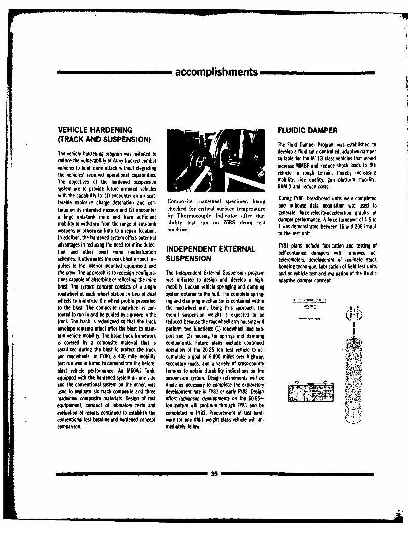
accomplishments
VEHICLE HARDENING FLUIDIC DAMPER(TRACK AND SUSPENSION) The Fluid Damper Program was established to
The vehicle hardening program was initiated to develop a fluidically controlled, adaptive damperreduce the vulnerability of Army tracked combat suitable for the M] 13 class vehicles that would
vehicles to land mine attack without degrading increase MMBF and reduce shock loads to the
the vehicles' required operational capabilities. vehicle in rough terrain, thereby increasingThe objectives of the hardened suspension mobility, ride quality, gun platform stability,system are to provide future armored vehicles RAM-D and reduce costs.with the capability to: (1) encounter an air scat- During FY80, breadboard units weie completedterable explosive charge detonation and con- Composite roadwheel specimen beingtinue on its intended mission and (2) encounter checked for critical surface temperature and in-house data acquisition wa: used to
a large anti-tank mine and have sufficient by Thermocouple Indicator after dur- generate force-velocity-acceleration graphs of
mobility to withdraw from the range of anti-tank ability test run on NBS drum test damper performance. A force turndown of 4.5 to
machine. 1 was demonstrated between 16 and 206 imputweapons or otherwise limp to a repair location, mahnto the test unit.
In addition, the hardened system offers potential
advantages in reducing the need for mine detec- FY81 plans include fabrication and testing oftion and other overt mine neutralization INDEPENDENT EXTERNAL self-contained dampers with improved ac-schemes. It attenuates the peak blast impact im- SUSPENSION celerometers, developemnt of laminate stackpulses to the interior mounted equipment and bonding technique, fabrication of field test unitsthe crew. The approach is to redesign configura- The Independent External Suspension program and on-vehicle test and evaluation of the fluidictions capable of absorbing or reflecting the mine was initiated to design and develop a high- adaptive damper concept.bast. The system concept consists of a single mobility tracked vehicle springing and dampingroadwheel at each wheel station in lieu of dual system exterior to the hull. The complete spring-wheels to minimize the wheel profile presented ing and damping mechanism is contained within FLUIDc 111 C1"IIUIT
to the blast. The composite roadwheel is con- the roadwheel arm. Using this approach, the ,s I-
toured to run in and be guided by a groove in the overall suspension weight is expected to be Itrack. The track is redesigned so that the track reduced because the roadwheel arm housing willenvelope remains intact after the blast to main- perform two functions: (1) roadwheel load sup-tain vehicle mobility. The basic track framework port and (2) housing for sprinp and dampingis covered by a composite material that is components. Future plans include continuedsacrificed during the blast to protect the track operation of the 20-25 ton test vehicle to ac-and roadwheels. In FY80, a 400 mile mobility cumulate a goal of 6,000 miles over highway,test run was initiated to demonstrate the before- secondary roads, and a variety of cross-countryblast vehicle performance. An M6OAI Tank, terrains to obtain durability indications on theequipped with the hardened system on one side suspension system. Design refinements will beand the conventional system on the other, was made as necessary to complete the exploratoryused to evaluate six track composite and three development late in FY81 or early FY82. Designroadwheel composite materials. Design of test effort (advanced development) on the 60-65+ -
equipement, conduct of laboratory tests and ton system will continue through FY81 and be Aevaluation of results continued to establish the completed in FY82. Procurement of test hard-.9)conventional test baseline and hardened concept ware for one XM-1 weight class vehicle will im-comparison, mediately follow.
35
t4
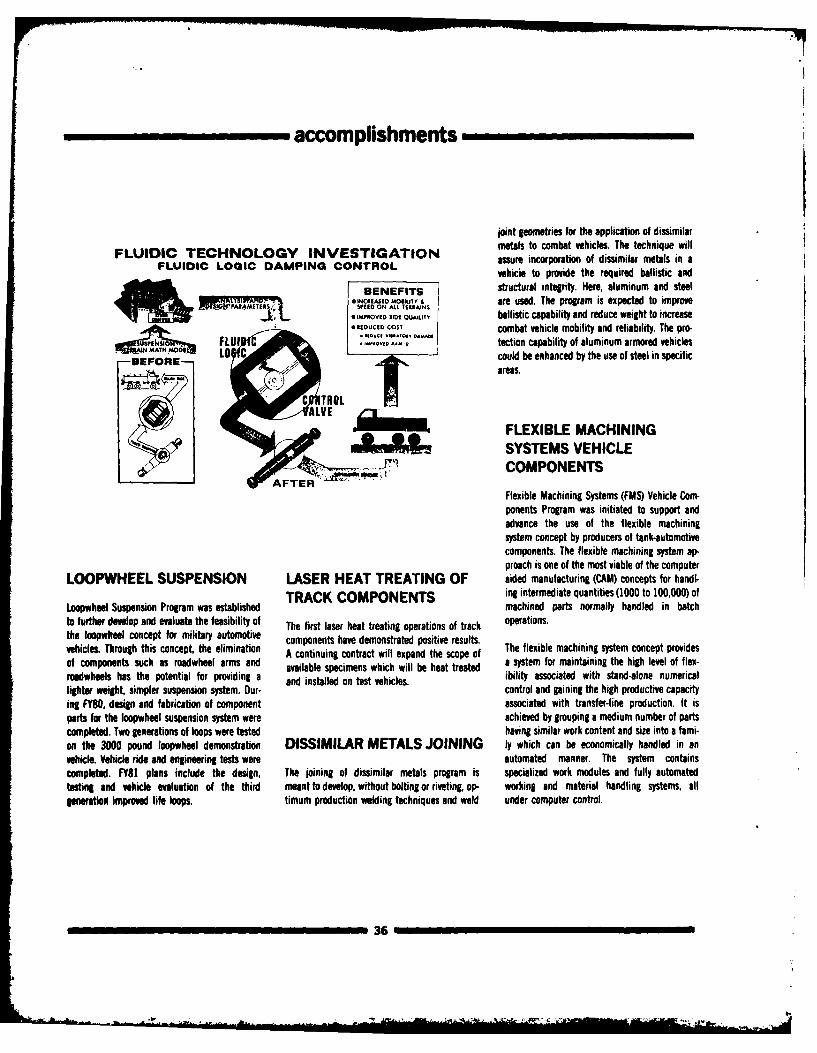
accomplishments
joint geometries for the application of dissimilarmetals to combat vehicles. The technique will
FLUIDIC TECHNOLOGY INVESTIGATION assure incorporation of dissimilar metals in aFLUIDIC LOGIC DAMPING CONTROL vehicle to provide the required ballistic and
BENEFITS structural integrity. Here, aluminum and steelo04R.soB.G MOMIY &are used. The program is expected to improvePARMETRSSPEED ON AL tIt RAINS
aMvEO Riot Q=L.1V ballistic capability and reduce weight to increaseA*RDUCEO COST combat vehicle mobility and reliability. The pro-
S NM ,,,,),M FLUI -011..e tection capability of aluminum armored vehicles
-BEFORE- could be enhanced by the use of steel in specificr areas.
C TROL
ALVEFLEXIBLE MACHININGSYSTEMS VEHICLE
AFTER COMPONENTS
Flexible Machining Systems (FMS) Vehicle Com-ponents Program was initiated to support and
advance the use of the flexible machiningsystem concept by producers of tank-automotive
components. The flexible machining system ap-proach is one of the most viable of the computer
LOOPWHEEL SUSPENSION LASER HEAT TREATING OF aided manufacturing (CAM) concepts for handl-
TRACK COMPONENTS in& intermediate quantities (1000 to 100,000) ofLoopwheel Suspension Program was established machined parts normally handled in batchto further develop and evaluate the feasibility of The first laser heat treating operations of track operations.the loopwheel concept for military automotive components have demonstrated positive results.vehicles. Through this concept, the elimination A continuing contract will expand the scope of The flexible machining system concept providesof components such as roadwheel arms and available specimens which will be heat treated a system for maintaining the high level of flex-roadwheels has the potential for providing a and installed on test vehicles. ibility associated with stand-alone numericallighter weight, simpler suspension system. Dur- control and gaining the high productive capacity
ing FY80, design and fabrication of component associated with transfer-line production. It isparts for the loopwheel suspension system were achieved by grouping a medium number of partscompleted. Two generations of loops were tested having similar work content and size into a fami-on the 3000 pound loopwheel demonstration DISSIMILAR METALS JOINING 4y which can be economically handled in anvehicle. Vehicle ride and engineering tests were automated manner. The system containscompleted. FY81 plans include the design, The joining of dissimilar metals program is specialized work modules and fully automatedtesting and vehicle evaluation of the third meant to develop, without bolting or riveting, op- working and material handling systems, allgeneration improved life loops. timum production welding techniques and weld under computer control.
36
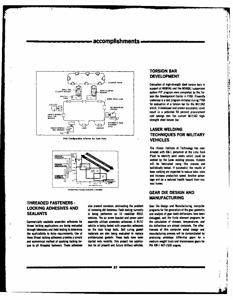
accomplishments___
TORSION BARDEVELOPMENT
CLUTE TRACK Evaluation of high-strength steel torsion bars in
AKL TAP LUTE support of ARMYAL and the M54BAl suspension4.O.UL OU, system PIP program were completed by the Tor- 4
- usion Bar Development Center in FY80. Presently'-O - *OA PIECE LOOP underway is a test program initiated during FY80
NC for evaluation of a torsion bar for the MI 13A2
CRERA|IS LMO which, if developed and proven successful, couldL .L result in a potential 50 percent procurement
0R1LL TAP -. U-L__J cost savings over the current Ml13A2 high-M L E --- A--,OMATIC strength steel torsion bar.
F-71 AUTOMATIC TOOLCHANGER
SIMOPNGLE LOAD UNLOAD AC
MILE III LASER WELDINGTECHNIQUES FOR MILITARY
MS Coniguratio. Scheme ot Tank Part, VEHICLES
The Illinois Institute of Technology has coor-dinated with XM-1 personnel at the Lima Tank
.CAT- Plant to identify joint welds which could bewelded by the Laser welding process. H-plates
A will be fabricated using this process andballistically tested. If successful, the results oflaser welding are expected to reduce labor costsand increase production speed. Another advan-tage will be a reduced health hazard from nox-ious fumes.
GEAR DIE DESIGN ANDMANUFACTURING
THREADED FASTENERS -also prevent corrosion, eliminating the problem Gear Die Design and Manufacturing, computerLOCKING ADHESIVES AND of removing old fasteners. Field testing currently programs for the generation of the gear geometry
SEALANTS is being performen on 10 modified M551 and analysis of par tooth deflections have beenvehicle& The air screw bracket and power plant debugged, and the finite element programs for
Commercially available anaerobic adhesives for assembly utilized anaerobic adhesives. A M151 the calculation of stresses, temperatures, andthread locking applications are being evaluated vehicle is being tested with anaerobic adhesives die deflections are almost complete. The effec-through laboratory and field testing to determine on the door hingp bolts. Self curing gasket tiveness of this computer aided design andthe applicability to Army requirements. Use of materials are also being evaluated to replace manufacturing process will be demonstrated bythese thread locking adhesives provides a simple prefabricated gaskets, These tests have been producing prototype differntial gears for aand economical method of applying locking tor- started only recently. This project has applica- medium weight truck and transmission gears forque to all threaded fasteners. These adhesives tion for all present and future military vehick, the XM- AGT-1500 engine.
3I
accomplishments
ELECTRODES FOR WELDING mo. Two contracts were initiated to provide a SUPPLEMENTAL ARMORtotal of 20 castings each representing both cast
STEEL ARMOR plate and the simulation of a cast turret section. ENGINEERING SUPPORT -Both contractors have submitted flat plates 5 in- XMZ
Several electrodes for welding steel armor were ches thick for ballistic evaluation. Results haveselected based on performance in all tests. shown that production cast plates can be Technical support for the XM1 Project ManagerBallistic plates are being fabricated and accep- fabricated and heat treated to provide a material in the development, direction, and analysis oftance will be based on weld integrity when apability that exceeds the minimum ballistic ballistic test programs included test and evalua-ballistically fired during Phase Ill, scheduled for equirements of the rolled armor specification tion of an improved steel air intake grille designFY81. In FY79, Phase II testing of candidate (MIL-A- 2560). and the development of a test method for accep-electrodes was carried out to determine Charpy tance evaluation of thin gauge alloy steel plate.V-notch values at minus 600F, tensile strength, Support effort through informal discussions atdyield strength, elongation, and to make bend and written comment was provided on armorcruciform tests& material and design application questions.
FABRICATION OF FLAT THIN-GAGE ALLOY STEEL PLATE
CAST ARMOR REPAIR The Thin-Gage Alloy Steel Plate project wasestablished to improve manufacturing pro-
Large armor castings to MIL-A-11356E are ac- cedures to produce closer flatness tolerances. OVERHEAD THREATScepted tosed only on calculations. Actual The contractor established procedures usingtallistic firings have not been performed to platten die quenching followed by roller leveling A matrix of possible lightweight supplementalverify or supplement the calculations. The Cast that produced improved plate flatness. In addi- armor composites (a maximum allowable weightArmor Repair program consists of preparing tion, manufactured plates were subjected to increase of 70 Ib/sq ft) to provide vehiclesimulated repairs of the following casting periodic flatness measurements to establish the overhead protection was developed for cost andthicknesses, heat treatments and defect sizes: effects of storage for periods up to 90 days. evaluation at Aberdeen Proving Grounds against4 x 60 x 60, Class B, Size 1, 2 and 3; 4 X 36 x both small shaped charges and self-forging60, Class C, Size 1; 1% x 60 x 60, Class B, Size fragments. To date, 50 percent of the target con-1, 2 and 3; and 1% x 36 x 36, Class C, Size 1. figurations have been tested.Upon completion, the cast plates will be shippedto Aberdeen Proving Grounds for ballistic firing. LIGHTWEIGHT ARMORThe results will be evaluated and necessary METALS FOR HIGHmodifications made to conform to MIL-A-11356E. EXPLOSIVE FRAGMEN-
TATION PROTECTION COMPOSITE ARMOR
The Lightweight Armor Materials for High Ex- Another system of composite armor materialplosive Fragmentation Protection Program was design was defined for test and evaluation inIMPROVED LARGE ARMOR concluded in FY80. This effort has expanded the FY80. The design is a spaced applique concept
STEEL CASTINGS established TARADCOM high explosive (HE) shell incorporating steel armor plate, ceramic insertfragment armor design computer code to include elements, and aluminum armor plate. This
Research has proven that ballistic performance mortar rounds (81mm and 60mm) and material system should afford a lightweight ar-of cast steel armor can be improved to equal roll- lightweight armor materials, i.e., doron, and mor design for protection against intermediatead steel armor by the use of controlled solidifica- bonded and unbonded nylon and kevlar. to high velocity kinetic energy weapons throughtion methodology. This project was initiated to Previous data base was limited to two HE frag- 30mm in diameter. The Composite Armor Projectdemonstrate production feasibility and to ment projectile threats (105mm and 155mm) entails a phased evaluation of ballistic protec-establish methods and procedures for general and two armor materials (rolled steel and tion capabilities of various material systemsuse in the manufacture of an improves cast ar- aluminum), which can reduce armor weight and/or simplify
-138
accomplishments
arrangements of high hardness steel on optics, and electronic gear such as computers tor (MPOEC) Project purpose is to develop an op-aluminum armor (7039 alloy) ranging in weight and radios. The work effort should provide a tional material to replace the current steel andfrom 12 lb/ft2 to 55 lb/ft . Test effort was in- more quantitative approach for evaluating shock aluminum ordnance electrical connectors withitiated at the Materiel Test Directorate, Aberdeen damage potential and needed protective plastic molded connectors to eliminate corrosionProving Grounds in Jan 79 involving ballistic measures to assure component survivability in problems and reduce weight and cost. Connec-tests against 7.62mm and 14.5mm AP projec- the typical combat shock environment, i.e., large tors were fabricated from thermoplastictiles. The test was completed in Jul 80. The test caliber non-penetrating armor piercing projectile polyester "Valox 420" and successfully com-information will provide the needed reference impacts, and high explosive (HE) blast (mines, pleted validation and laboratory testing and aredata base for proper use of this type of com- shaped charges, and HE shells). interchangeable, intermateable, and intermoun-posite armor system for vehicle design. table with existing metal connectors. Field tests
were conducted on 15 vehicles and the plasticconnecters wire intermounted with steel recep-tables. The field tests were conducted at -650F
NATO ARMOR PROTECTION/ (-54°C) on MI5i jeeps and on M113 personnel
VULNERABILITY MODEL carriers in Alaska. Tests at Yuma ProvingGrounds were on the M113, M60, M818 and
The Spell Protection effort was intended to ex- STANDARDIZATION M54 vehicles. The results show that after twopand TARADCOM's computer design capability to years there have been no failures or deteriorationinclude considerations of spall liners in an ar- This effort is in support of the NATO Armor Pro- of MPOEC's and they are a satisfactory replace-
mored vehicle. Using an existing armor design tection/Vulnerability Model Standardization Pro- ment for the standard metal connector. Allcomputer program, different analytical pro- gram to obtain a standard armor protec- MPOEC's remain installed on those vehicles incedures have been considered to account for the tion/vulnerability model. TARADCOM represen- their present mixed locations and are subject toeffects of various spall liners. It was determined tatives participated in special meetings with periodic observation.that only spallation caused by shaped charged technical representatives of NATO Working Group(HEAT) projectiles can be significantly reduced 2, AC/225 Panel II, to define and agree on com-by liners. It also was found that only soft target mon reference target to permit comparison ofareas will benefit from the use of spall liners, various national vulnerability models. The T-62A HIGH-STRENGTHTherefore, the analytical consideration of spall vehicle was designated for analysis. Vulnerability MATERIALS AND
liner effectiveness is limited to computations in- analysis was performed with the TACOME3 com-
volving crew compartment areas when threaten- puter model. Results were compiled and COMPONENTSad by shaped charged projectiles. Work has been documented. Target emphasis then was viewedconcentrated on devising a different analytical more desireable in view of work interests of the High-strength materials can offer improved com-approach for this situation. Adjustments to pro- majority of working group participants. Because ponent reliability and decreased vehicle life-bablility of kill curves and/or material thickness of classification considerations, release of com- cycle costs. Lightweight, high-strength materialscould provide a practical solution. mon reference drawings could not be made by can offer increased vehicle performance and fuel
Ballistic Research Laboratory (BRL) to all group efficiency, which is important during the energymembers. Analysis was started by TARADCOM to crisis. The objective of this program is to developpermit preliminary comparison with similar ef- criteria for designing and fabricating large com-
DESIGN METHODS FOR fort by BRL. This early initiative will generate ponents for high-strength materials. Part of thisresults for working group meetings tentatively program effort was concentrated on the
BALLISTIC SHOCK scheduled for Nov 80. M60/XM-1 tow bar. The tow bar currentlyauthorized for issue is heavy and cumbersome
A contract was negotiated for the development (340 lbs., 8% ft. long). For greater self-recoveryof predictive design procedures and protection MOLDED PLASTIC capability, a lightweight tow bar with the samemethods for shielding tank critical components performance characteristics is required. Com-can be damaed by a ballistic impact or high ex- ORDNANCE ELECTRICAL posites, which offer a high directional strength-
plosive blast even though the vehicle survives the CONNECTOR to-weight ratio, increased stiffness, and lowattack. Examples of components that must be machining costs for this application. An evalue-shock mounted are the fire control equipment, The Molded Plastic Ordnance Electrical Connec- tion of the various composite properties, their
39
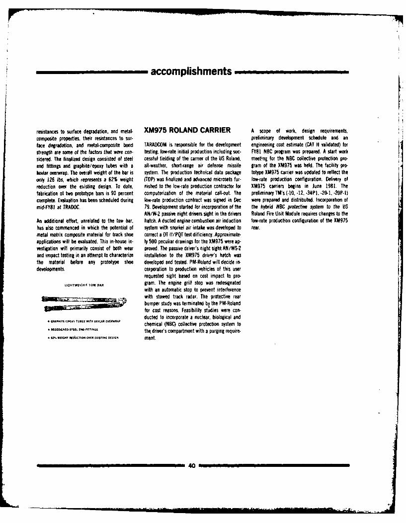
accomplishments ,_,
resistances to surface degradation, and metal- XM975 ROLAND CARRIER A scope of work, design requirements,composite properties, their resistances to sur- preliminary development schedule and anface degradation, and metal-composite bond TARADCOM is responsible for the development engineering cost estimate (CAT II validated) forstrength are some of the factors that were con- testing, low-rate initial production including suc- FY81 NBC program was prepared. A start worksidered. The finalized design consisted of steel cessful fielding of the carrier of the US Roland, meetig for the NBC collective protection pro-end fittings and graphite/epoxy tubes with a all-weather, short-range air defense missile gram of the XM975 was held. The facility pro-kevlar overwrap. The overall weight of the bar is system. The production technical data package totype XM975 carrier was updated to reflect theonly 126 lbs, which represents a 62% weight (TDP) was finalized and advanced microsets fur- low-rate production configuration. Delivery ofreduction over the existing design. To date, nished to the low-rate production contractor for XM975 carriers begins in June 1981. Thefabrication of two prototype bars is 90 percent computerization of the material call-out. The preliminary TM's (-10, -12, -34PI, -20-1, -20P-1)complete. Evaluation has been scheduled during low-rate production contract was signed in Dec were prepared and distributed. Incorporation ofmid-FY81 at TRADOC. 79. Development started for incorporation of the the hybrid NBC protective system to the US
AN/W-2 passive night drivers sight in the drivers Roland Fire Unit Module requires changes to theAn additional effort, unrelated to the tow bar, hatch. A ducted engine combustion air induction low-rate production configuration of the XM975has also commenced in which the potential of system with snorkel air intake was developed to rear.metal matrix composite material for track shoe correct a DT II/PQT test dificiency. Approximate-applications will be evaluated. This in-house in- ly 500 peculiar drawings for the XM975 were ap-vestigation will primarily consist of both wear proved. The passive driver's night sight AN/WS-2and impact testing in an attempt to characterize installation to the XM975 drivir's hatch wasthe material before any prototype shoe developed and tested. PM-Roland will decide in-developments, corporation to production vehicles of this user
requested sight based on cost impact to pro-
LIGHTWEIGIIT TOW BAR gram. The engine grill stop was redesignatedwith an automatic stop to prevent interferencewith stowed track radar. The protective rearbumper study was terminated by the PM-Rolandfor cost reasons. Feasibility studies were con-ducted to incorporate a nuclear, biological and
6 GRAPHITE/tPOXY ?UBES WITH KAVLAN OV (RWRAP chemical (NBC) collective protection system to6 .99IGNDo STEEL END FITTINGS tht driver's compartment with a purging require-* 62% WEIGHT RE JCTION OVER EXISTING DESIGN ment.
40
accomplishments
TANK-AUTOMOTIVE CONCEPTS LABORATORY
SURVIVABILITY Analysis Agency (TRASANA) and other agencies. A fire cannon, a feasible weapon system. '
OPTIMIZATION MODEL variety of cannon and missile system weapon sta-tions were configured for these designs. Crew The ACVT Program's purpose is to establish the
The TARADCOM Survability Optimization Model sizes range from two to four and for some con- technical, military, and economic basis and con.(SOM) has become operational and is used to cepts the requirement to carry up to three addi- cept feasiblilty of light weight armored combatevaluate future close combat vehicle concepts. tional persons was met. vehicles and medium caliber automatic cannons.The SOM provides a capability to assess bat- The Armor Engineer Board (AEB) is the agencytlefield survivability while a vehicle is still in the Both wheeled and tracked vehicles were studied responsible for the overall effort. However,concept stage. The model setup and operation in weight ranges from 16 to 40 tons. TARADCOM has been actively involved in pro.costs are lower than the usual combat models, viding extensive support.permitting more extensive analysis. The concepts In many instances new models had to bestudies so far represent three possibilities for the developed and existing models had to be TACL has used a gamut of existing computerizedsuccessor to the XMI: a conventional turreted modified. For example, the mathematical mathematical simulations in selecting field teststank, a casemate tank, and a tank with an simulation of a tracked vehicle performing a tur- conditions.elevated gun. The low cost of operation of the ning maneuver under off-road conditions wasSOM permits the characteristics of the concepts developed specifically in support of the Armoredto be varied to show improvements and to ex- Combat Vehicle Technology (ACVl) program.plore the sensitivity of the results. Other models used included the NATO reference ARMORED COMBAT
mobility model, ride dynamics models, power- VEHICLE SCIENCE ANDtrain simulation, vehicle signature model, andfiring (platform) stability models. These vehicle TECHNOLOGY BASEconcepts are evaluated by means of the PROGRAMARMO ED C MBATmathematical simulations.
ARMORED COMBAT in recognition of Armored Combat VehicleVEHICLE TECHNOLOGY Science and Technology (S&T) Program conceptsPROGRAM SUPPORT The output of these models is used for detailed accomplishments, the following tasks were
combat vehicle performance analysis under a assigned and completed in FY80:The Tank-Automotive Concepts Laboratory (iACL) variety of conditions. The data will be employedExploratory Development Division has generated by TRASANA as inputs for force-on-force combat (1) Expansion in the S&T scope beyond tanks35 lightweight vehicle concepts in support of the simulation to predict overall military effec- to include all combat vehicles in a close combatArmored Combat Vehicle Technology Program. tiveness. maneuver unit which are within TARADCOM'sConcepts designs were finalized for 25 of these mission area.selected by the Armor Engineer Board (AEB). It is expected that the Concept Laboratory's sup- (2) Defining future combat weapon systems
port will be of considerable worth to the US Ar- towards which the technology efforts throughoutDesign and performance data for these concep- my in arriving at the answer to the question rais- the development community will be focused.tual vehicles were furnished to the AEB, Ballistic ed by the Chief of Staff: "Is a light weight, agileResearch Laboratory (BRL), TRADOC Systems combat vehicle, which is equipped with a rapid The broadening of scope increased user
41
- ,'-
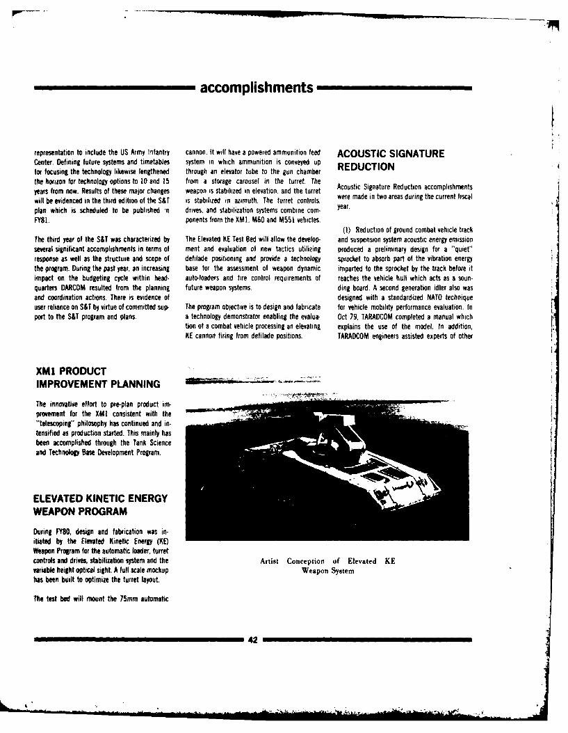
accomplishments
representation to include the US Army Infantry cannon. It will have a powered ammunition feed ACOUSTIC SIGNATURECenter. Defining future systems and timetables system in which ammunition is conveyed up REDUCTIONfor focusing the technology likewise lengthened through an elevator tube to the gun chamber
the horizon for technology options to 10 and 15 from a storage carousel in the turret. Theyears from now. Results of these major changes weapon is stabilized in elevation, and the turret A
will be evidenced in the third edition of the S&T is stabilized in azimuth. The turret controls, were made in two areas during the current fiscal
plan which is scheduled to be published -n drives, and stabilization systems combine com- year.
FY81. ponents from the XM1, M60 and M551 vehicles.(1) Reduction of ground combat vehicle track
The third year of the S&T was characterized by The Elevated KE Test Bed will allow the develop- and suspension system acoustic energy emissionseveral significant accomplishments in terms of ment and evaluation of new tactics utilizing produced a preliminary design for a "quiet"response as well as the structure and scope of defilade positioning and provide a technology sprocket to absorb part of the vibration energythe program. During the past year, an increasing base for the assessment of weapon dynamic imparted to the sprocket by the track before itimpact on the budgeting cycle within head- auto-loaders and fire control requirements of reaches the vehicle hull which acts as a soun-quarters DARCOM resulted from the planning future weapon systems. ding board. A second generation idler also wasand coordination actions. There is evidence of designed with a standardized NATO techniqueuser reliance on S&T by virtue of committed sup- The program objective is to design and fabricate for vehicle mobility performance evaluation. inport to the S&T program and plans. a technology demonstrator enabling the evalua- Oct 79, TARADCOM completed a manual which
tion of a combat vehicle processing an elevating explains the use of the model. In addition,KE cannon firing from defilade positions. TARADCOM engineers assisted experts of other
XM1 PRODUCTIMPROVEMENT PLANNING
The innovative effort to pre-plan product im-provement for the XMI consistent with the"telescoping" philosophy has continued and in-tensified as production started. This mainly hasbeen accomplished through the Tank Scienceand Technology Base Development Program.
ELEVATED KINETIC ENERGY
WEAPON PROGRAM
During FY80, design and fabrication was in-itiated by the Elevated Kinetic Energy (KE)Weapon Program for the automatic loader, turretcontrols and drives, stabilization system and the Artist Conception of Elevated KEvariable height optical sight. A full scale mockup Weapon Systemhas been built to optimize the turret layout.
The test bed will mount the 75mm automatic
42
.-. . £~*I
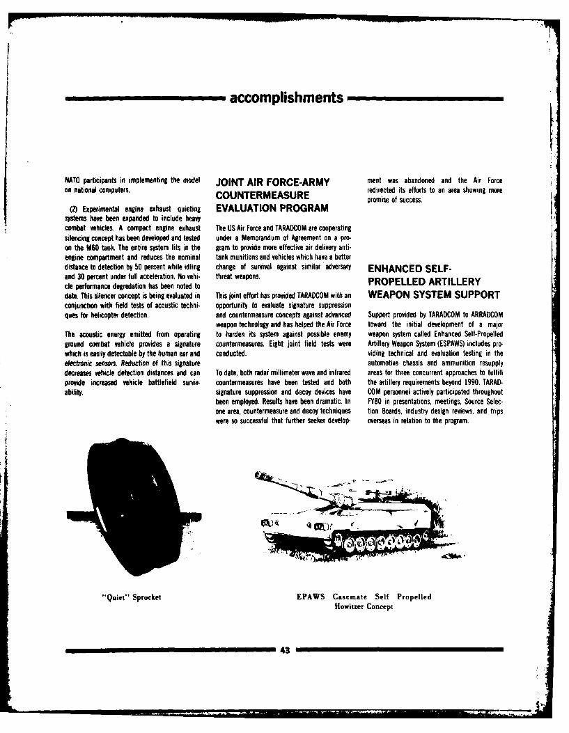
,,,___,, ___ accomplishments
NATO participants in implementing the model JOINT AIR FORCE-ARMY ment was abandoned and the Air Forceon national computers. redirected its efforts to an area showing moreCOUNTERMEASURE promise of success.
(2) Experimental engine exhaust quieting EVALUATION PROGRAMsystems have been expanded to include heavycombat vehicles. A compact engine exhaust The US Air Force and TARADCOM are cooperatingsilencing concept has been developed and tested under a Memorandum of Agreement on a pro-on the M60 tank. The entire system fits in the gram to provide more effective air delivery anti-engine compartment and reduces the nominal tank munitions and vehicles which have a betterdistance to detection by 50 percent while idling change of survival against similar adversary ENHANCED SELF-and 30 percent under full acceleration. No vehi- threat weapons. PROPELLED ARTILLERYcle performance degredation has been noted todate. This silencer concept is being evaluated in This joint effort has provided TARADCOM with an WEAPON SYSTEM SUPPORTconjunction with field tests of acoustic techni- opportunity to evaluate signature suppressionques for helicopter detection. and countermeasure concepts against advanced Support provided by TARADCOM to ARRADCOM
weapon technology and has helped the Air Force toward the initial development of a majorThe acoustic energy emitted from operating to harden its system against possible enemy weapon system called Enhanced Self-Propelledground combat vehicle provides a signature countermeasures. Eight joint field tests were Artillery Weapon System (ESPAWS) includes pro-which is easily detectable by the human ear and conducted. viding technical and evaluation testing in theelectronic sensors. Reduction of this signature automotive chassis and ammunition resupplydecreases vehicle detection distances and can To date, both radar millimeter wave and infrared areas for three concurrent approaches to fulfillprovide increased vehicle battlefield surviv- countermeasures have been tested and both the artillery requirements beyond 1990. TARAD-ability, signature suppression and decoy devices have COM personnel actively participated throughout
been employed. Results have been dramatic. In FY80 in presentations, meetings, Source Selec-one area, countermeasure and decoy techniques tion Boards, industry design reviews, and tripswere so successful that further seeker develop- overseas in relation to the program.
i
"Quiet" Sprocket EPAWS Casemate Self PropelledHowitzer Concept
43
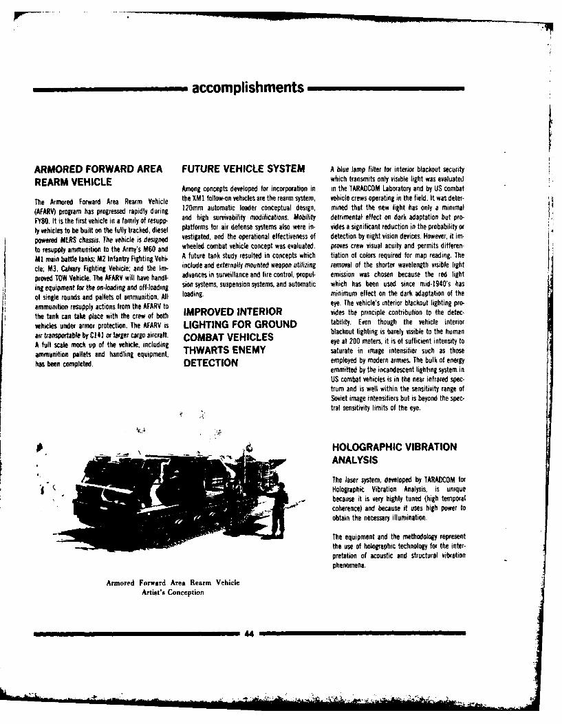
accomplishments
ARMORED FORWARD AREA FUTURE VEHICLE SYSTEM A blue lamp filter for interior blackout security
REARM VEHICLE which transmits only visible light was evaluatedAmong concepts developed for incorporation in in the TARADCOM Laboratory and by US combat
The Armored Forward Area Rearm Vehicle the XM1 follow-on vehicles are the rearm system, vehicle crews operating in the field. It was deter-(AFARV) program has progressed rapidly during 120mm automatic loader conceptual design, mined that the new light has only a minimal
Ff80. It is the first vehicle in a family of resupp- and high survivability modifications. Mobility detrimental effect on dark adaptation but pro-
ly vehicles to be built on the fully tracked, diesel platforms for air defense systems also were in- vides a significant reduction in the probability or
powered MLRS chassis. The vehicle is designed vestigated, and the operational effectiveness of detection by night vision devices. However, it im-
to resupply ammunition to the Army's M60 and wheeled combat vehicle concept was evaluated, proves crew visual acuity and permits differen-
M! main battle tanks; M2 Infantry Fighting Vehi- A future tank study resulted in concepts which tiation of colors required for map reading. The
cle; M3, Calvary Fighting Vehicle; and the Im- include and externally mounted weapon utilizing removal of the shorter wavelength visible light
proved TOW Vehicle. The AFARV will have handl- advances in surveillance and fire control, propul- emission was chosen because the red light
ing equipment for the on-loading and off-loading sion systems, suspension systems, and automatic which has been used since mid-1940's has
of single rounds and pallets of ammunition. All loading, minimum effect on the dark adaptation of theammunition resupply actions from the AFARV to eye. The vehicle's interior blackout lighting pro-
the tank can take place with the crew of both IMPROVED INTERIOR vides the principle contribution to the detec-
vehicles under armor protection. The AFARV is LIGHTING FOR GROUND tability. Even though the vehicle interior
air transportable by C141 or larger cargo aircraft. COMBAT VEHICLES blackout lighting is barely visible to the human
A full scale mock up of the vehicle, including eye at 200 meters, it is of sufficient intensity to
ammunition pallets and handling equipment, THWARTS ENEMY saturate in image intensifier such as those
has been completed. DETECTION employed by modern armies. The bulk of energyemmitted by the incandescent lighting system inUS combat vehicles is in the near infrared spec-trum and is well within the sensitivity range ofSoviet image intensifiers but is beyond the spec-
tral sensitivity limits of the eye.
01 HOLOGRAPHIC VIBRATIONANALYSIS
The laser system, developed by TARADCOM for
Holographic Vibration Analysis, is uniquebecause it is very highly tuned (high temporalcoherence) and because it uses high power to
obtain the necessary illumination.
The equipment and the methodology representthe use of holographic technology for the inter-pretation of acoustic and structural vibrationphenomena.
Armored Forward Area Rearm VehicleArtist's Conception
44i "
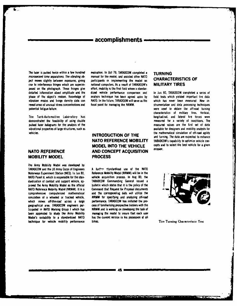
accomplishments
The laser is pulsed twice within a few hundred evaluation. In Oct 79, TARADCOM completed a TURNINGmicrosecond time separations. The vibrating ob- manual for the model, and assisted other NATOject moves slightly between exposures, giving participants in implementing the model on CHARACTERISTICS OFrise to interference fringes which are superim- national computers. As a result of TARADCOM's MILITARY TIRESposed on the photograph. These fringes give effort, mobility is the first field where a standar-detailed information about amplitude and the dized vehicle performance comparison and In Jun 80, TARADCOM completed a series ofphase of the object's motion. Knowledge of analysis technique has been agreed upon by field tests which yielded important tire datavibration modes and fringe density data can NATO. In the future, TARADCOM will serve as the which has never been measured. New in-reveal areas of unusual stress concentrations and focal point for managing the NRMM. strumentation and data processing techniquespotential fatigue-failure. were used to obtain the off-road turning
characteristics of military tires. Vertical,The Tank-Automotive Laboratory has longitudinal, and lateral tire forces weredemonstrated the feasibility of using double measured for a variety of conditions. Thepulsed laser holograms for the analysis of the measured values are the first set of datavibrational properties of large structures, such as available for designers and mobility analysts forvehicles. the mathematical simulation of off-road agility
INTRODUCTION OF THE and turning. The data are expected to enhanceNATO REFERENCE MOBILITY TARADCOM's capability to optimize vehicle con-
MODEL INTO THE VEHICLE cepts and to select the best vehicle for a given
NATO REFERENCE AND CONCEPT ACQUISITION mission.
MOBILITY MODEL PROCESS
The Army Mobility Model was developed byTARADCOM and the US Army Corps of Engineers A furth- • standardized use of the NATOWaterways Experiment Station (WES). In Jun 80, Reference Mobility Model (NRMM) will be in theNATO Panel 1I, which is responsible for the stan- vehicle acquisition process. In Aug 80, theJdardization of combat and support vehicle, ap- TARADCOM Commanding General issued aproved the Army Mobility Model as the official bulletin which states that it is the policy of theNATO Reference Mobility Model ( NRMM). It is a Command that Request for Proposal documentscomprehensive computerized mathematical and the corresponding bids will utilize thesimulation of a wheeled or tracked vehicle, NRMM for specifying and analyzing off-roadwhich moves off-the-road across a large performance. TARADCOM has initiated the pro-geographical area. TARADCOM engineers par- cess of familiarizing prospective bidders with theticipated in NATO Working Group I which has NRMM and is working on developing the task ofbeen appointed to study the Army Mobility managing the model to insure that each userModel's suitability to a standardized NATO has the current version in his possession at alltechnique for vehicle mobility performance times. Tire Turning Characteristic Test
45
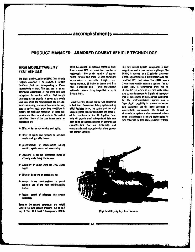
accomplishments
PRODUCT MANAGER - ARMORED COMBAT VEHICLE TECHNOLOGY
HIGH MOBILITY/AGILITY 1500; fire control - six software controlled levels The Fire Control System incorporates a laser
TEST VEHICLE from present M60 to closed loop; number of rangefinder and a tank thermal nightsight Theroadwheels - five or six; number of support HIMAG is powered by a 12-cylinder, air-cooled
The High Mobility/Alty (HIMAG) Test Vehicle rollers - three or four; track -24-inch aluminum; diesel engine through a X-1 100 transmission and
Program objective is to produce- a variable suspension - variable height, full modified M51 final drives. The HIMAG uses aparameter test bed incorporating a 75mm hydropneumatic, 16 inches in jounce and 6 in- 75mm hypervelocity automatic cannon. The ac-prmeter cannon.The test bed inc g an em ches in rebound; gun - 75mm hypervelocity quired data is telemetered from the in-
hpermenalc c aon. the est edvanced automatic cannon, firing single-shot or up to strumented test vehicle in real time as the entireperimental assemblage of the most advanced 6-round burst. data stream is recorded in digital and analog for-subsystems for combat vehicles that today's mat for subsequent off-line analysis. Additional-technologies can provide. It serves as a mobile ly, the instrumentation system has alaboratory which the Army research and develop- Mobility/agility chassis testing was completed "quick-look" capability to provide on-the-spotment comm,inity, in conjunction with the user, at Fort Knox. Government full-up system testing data assessment and the tiemly correction ofuses to perform tests under field conditions to which includes turret, fire control and the total unacceptable inaccuracies. The HIMAG in-explore the technical feasibility of these sub- weapon system, is being conducted and schedul- strumentation system is also considered to be asystems and their tactical worth on the modern ad for completion in Mar 81. Together, these noted break-through in today's technologies forbattlefield. Some of the core issues under in- tests will provide a well substantiated data basevestigation are: from which to support decisions on performance
characteristics that are technically and0 Effect of terrain an mobility and agility, economically most appropriate for future genera-
tion combat vehicles.* Effect of agility and mobility on anti-tank
missile and gun effectiveness.
* Quantification of relationships amongmobility, agility, armor and survivability.
* Capability to achieve acceptable levels ofaccuracy while firing onthe-move.
0 Suitability of 75mm guns for 1990 armor
targets,
0 Effect of burst-fire on probability hit
0 Human factors considerations to permitoptimum use of the high mobility/agilityfeature.
0 Tactical payoff of advanced fire contoltechnology.r
aSome of the variable parameters are: weight-33.5 to 45 sground prmure -85 to 117psi; HP/Ton -22.2 to 44.7; hnpfow - 1000 to High MobilitylAgility Test Vehicle
4a,
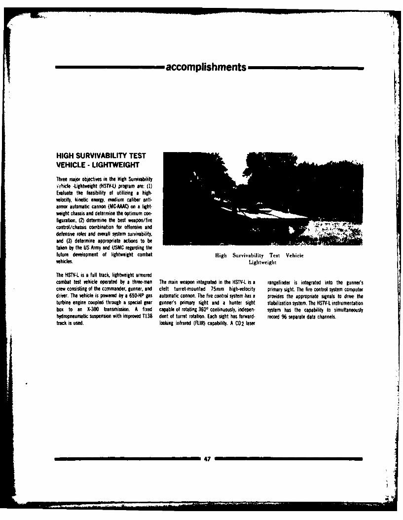
accomplishments
HIGH SURVIVABILITY TESTVEHICLE - LIGHTWEIGHT
Three maio objectives in the High Survivabilityvehicle -Lightweight (HSTV-L) program are: (1)Evaluate the feasibility of utilizing a high-velocity, kinetic energy, medium caliber anti-armor automatic cannon (MC-AAAC) on a light-weight chassis and determine the optimum con-figuration, (2) determine the best weapon/firecontrol/chassis combination for offensive anddefensive roles and overall system survivability,and (3) determine appropriate actions to betaken by the US Army and USMC regarding thefuture development of lightweight combat High Survivability Test Vehiclevehicles. Lightweight
The HST -L is a full track, lightweight armoredcombat test vehicle operated by a three-man The main weapon integrated in the HSTV-L is a rangefinder is integrated into the gunner'screw consisting of the ccnmander, gunner, and cleft turret-mounted 75mm high-velocity primary sight. The fire control system computerdriver. The vehicle is powered by a 650-lP gas automatic cannon. The fire control system has a provides the appropriate signals to drive theturbine engine coupled through a special gear gunner's primary sight and a hunter sight stabilization system. The HSTV-L instrumentationbox to an X-300 transmission. A fixed capable of rotating 3600 continuously, indepen- system has the capability to simultaneouslyhydropneumatic suspension with improved T138 dent of turret rotation. Each sight has forward- record 96 separate data channels.track is used. looking infrared (FLIR) capability. A C02 laser
47
accomplishments
PROJECT MANAGER FOR IMPROVED TOW VEHICLE
FIRE SUPPORT TEAM TARADCOM and TARCOM proposing the transfer Action was taken to establish an ADP program
VEHICLE of the ITV to TACON on I Oct 81. designed to extract needed procurement data onall Authorized Stockage List/Prescribed Load
On 25 Jan 80, a multi-year contract for the last List Items.The concept of transitomna the Fire Support 910 M901's was awarded. This will result in aTeam Vehicle (FIST) System, as portrayed by the total FY77 - FY82 program of 1982 vehicles and Depot Maintenance Work RequirementsFISTV Transition Plan approved 5 Aug 80. envi- 38 turret trainers with a budget of $263.6 (DMWRS) which provide depot support of thesions the transfer of the total systems respon- million. Delivery of the last (1982nd) M901 is ex- squad leader's periscope, image transfersibility from PM ITV/FISTV to TACOM in May pected in Aug 82. assembly, launcher and erector arm, cupola and1986. gunner's seat, and the final assembly have been
Two product improvement programs (PIPs) were validated adn verified.A subcontract for development of a North Seek- initiated by PM-I"V to enhance the M901ing Gyrocompass (NSG) for the FIST was award- capabilities and to keep abreast of im- Deployment began in Aug 79 and greatly increas-ed in Apr 80. The FISTV Systems Model has been provements of related items. One deals with the ed during FY80. Emphasis was placed on deploy-fabricated and is undergoing a three month TOW Vehicle Power Conditioner (TVPC). Installa- ment to Europe first and then CONUS. AllSystems Model Test (SMD IA with prototype and tion of the TVPC in the M901 will allow use of deployment is scheduled for completion in Octbrassboard hardware. After SMT IA the vehicle the vehicle electrical system to power the TOW 82.will be refurbished and upgraded with prototype Missile Guidance Set (MGS) thereby increasingsubsystems for a second test, SMT B. which reliability and the readiness posture. Applicationwill last for two months. This program is ex- of this kit will be accomplished during the first
pected to find and correct many problems prior ofter kit on be a d ur rst
to te enineringdesgn tst.quarter FY81 on 1982 M9Ols and 38 Turretto the engineering design test. Trainers. Another PIP identified as TOW 2 in-
tegrated the enhanced capabilities of the Im-proved TOW missile incorporates an ability tocounter electro-optical countermeasures, smoke
IMPROVED TOW VEHICLE environment capability and enhance armor pier-M901 cing capability. Modifications to the M901 are
required in the ITV electrical wiring harnessesA Transition Plan was approved and signed on 22 and stowage. These PIPs will tremendously in-October 1979 by the Commanders of both crease the M9Os lethality and survivability.
48
' J. L "' " " ...-"
indicators
ACTIVITIES
TECHNICAL PAPERS AND from Millimeter Wave Seekers," by Gordon Automotive Command" by Dr. Water Bryzik, 5-7
PRESENTATIONS Mclnnes and Dr. John Bennett (presented by Dr. Jul 80, Workshop on International CombustionBennett), at the Second Annual Keweenaw sponsored by the Army Research Office, Imperial
"Activity Report to the Technical Management Research Center Ground Vehicle Infrared College, London, England.
Committee," by Peter W. Haley, Nov 79, to NATO Signature Symposium, Jul 80, at Houghton, MI.Reference Mobility Model meeting, at Frankfurt, "Advanced Higih Temperature Diesel EngineGermany "The KRC/TARADCOM Ground Infrared Research" by Dr. Walter Bryzik, Jul 79, Interna-Signature Model," coauthored by Dave Wilburn, tional Engine Combustion Workshop, University
"Reduced Order Filter for Lineir Discrete-Time at meeting of the IRIS Specialty Group on of Wisconsin, Madison, WI.
Systems with Measurements Containing Colored Targets, Backgrounds and Discrimination, Jul80,Noise," "Dynamic Analysis of Articulated M113 at Arlington, VA. "Multifuel Characteristics of Diesel Engines" byAPCs "....Dynamic Analysis of ighla Mbility "EDr. Walter Bryzik 17 Oct 79, Fuels ProcessingAPs, .."Dynamic Analysis of High Mobility "Engine Research and Development" by Dr. Paul Workshop, sponsored by Army Research Office,Tracked Vehicle," co-authored and presented by C. Glance, 27-28 Mar 80, ADPA Transport USC, Pasadena, CA.Dr. Ronald R. Beck, at Eleventh Annual Pitt- Meeting, Monterey, CA.sburgh Conference, School of Engineering, "Advanced Techniques for Electrical PowerUniversity of Pittsburgh, 2 May 80, Pittsburgh, "Multituel Engine Developments" by George E. Management, Control, and Distribution SystemsPA. Cheklich, 17 Oct 79, Army Research Office (ATEPS)" by Donald S. Sams and Marquis W."Vehicle Mobility or Firing Stability, a Delicate Emergency Fuels Workshop, Pasadena, CA. Woody, 30 Oct 79, to Colonel McConnal, Armor
Balance," presented by Frank Hoogterp and Dr. "Advanced Piston Engine Program" by George E. and Engineering Board, Ft Knox, KY.
Ronald R. Beck at the 1980 USA Science Con- Cheklich, 7 Aug 80, to Mr. R. Standahar, OSD, at "ATEPS" by Donald S. Sarna, 19 Feb SO, toference, Jun 80, West Point, NY. TACOM, Warren, Mi. General Starry, at TArOM, Warren, MI.
"Direct Electronic Fourier Transform Spectra for "Tribology Needs in Advanced Diesel Engines"Surveillance and Countersurveillance," co by George E. Cheklich, 5 Aug 80, Army Research "Simplified Test System Evolution" by Donald S.authored and presented by Dr. Grant Gerhart, it Office Workshop on TriboloTD, RCnsselaer SaDe , Ft Monroe, VA.the Society of Photothermic Instrumentation Polytechnic Institute, Troy, Mi.Engineers (SPIE) meeting, Jul 80, San Diego, CA.
"Ceramics for the Adiabatic Turbocompound "Simplified Test System Evolution" by Donald S."Holographic Analysis of Large Vehicle Struc- Engine" by Dr. Walter Bryzik, 10-13 Oct 79, 6th Sarna, 2 Apr 80, to DA, Washington, DC.hbres," coauthored and presented by Dr. Grant Army Materiels and Mechanics Research CenterGrhart, at the 50th Shock and Vibration Sym- Materials Technology Conference - Ceramics for "Simplified Test Equipment-Expendablepoium, 21 Oct 79, Colorado Springs, CO. High Peformance Applications III - Reliability, (STE-)" by Donald S. Same, 28 May 80, OSO,
Orcas Island, WA. Washington, DC."TARADCOM/KRC Vehicle Signature Model Up.date" by Dave Wilburn; "Infrared Signature on "Adiabatic Turbocompound Engine Performance "Improving Land Vehicle Maintonance via Ap.XM-i Battle Tank" coauthored by Dov Wlbum Prediction" by Dr, Walter Dryzik Oct 79, plication of Evolving Diagnostic, Prognostic andand Wallace Mick (posented by Wilbum), "In- Japanese Society of Mechanical Engineers Tran- Electrical Power Distribution Systemsfrared Signatures of Soviet Amored Combat sections, Volume 18, No. 225, pages 9.18. TechnoloW' by Donald S. Se, 25 Aug 80, toVehicles," by Wallace Mick; "Passive Council of the American Trucking Association atContomeasrm es to Protect Militay Vehicles "Engine Research Program of the US Army Tank- Hyatt Regency, Darborn, Mi
494
hA
indicators
"Track Pin Induced Stress" by S. B. Catalano Session chairman, 26th Conference of Army VEHICLE SUSPENSION USING PRESSURIZEDand . T. Allen, presented by Catalano, 27-29 Mathematicians, Jun 80, on-going assignment at BOURDON TUBESNov 79, b the 28th Defense Conference on various locations. Dr. James L. Thompson. Ser No 101,932 file 10 Dec 79Nondestructive Testing, Pensacola Beach, FL. by Dr. Ernest N. Petrick
"Army Engineers Ask the Question: Can Your MOTOR-DRIVEN WINCH HAVING INTERNALTrailer Make the GradeT' by Grad Salerno, edited PATENT APPLICATIONS SPEED REDUCERby George J. Bodnar and Jerome T. Cipkowski, FILED Ser No 108,897 filed 31 Dec 79published May 80, Trailer Body Builders. (1 Oct 79 - 30 S. ) by Erwin F. Geppert
"Tactical Vehicle Fleet - Present and Future" by RESIDUE ACCOMMODATION MEANS FOR A GASRoger R. Gay, 27 Mar 80 to American Defense MEANS FOR SECURING TWO ELEMENTS OPERATIONAL GUNPreparedness Association (ADPA), Monterey, CA. AGAINST RELATIVE AXIAL MOVEMENT Ser No 108,466 filed 31 Dec 79
Ser No 082,398 filed 15 Oct 79 by James J. Healy"Heavy Expanded Mobility Tactical Truck" by by Erwin F. GeppertDennis E. Mazurek, 27 Mar 80, to ADPA, FIRE SUPPRESSANT IMPACT DIFFUSERMonterey, CA. MEANS TO MINIMIZE THE BACKLASH OF Ser No 111,040 filed 10 Jan 80
MESHING GEARS beto J. Mone an 80"High Mobility Multi-Purpose Wheeled Vehicle" Set No 088,433 filed 26 Oct by Anthony J. Monte and Ernest C. Wahoskiby George J. Bugarin, 27 Mar 80, to ADPA, by Martin J. NeumeyerMonterey, CA. COMPOSITE CORED COMBAT VEHICLE ARMOR
BOOM LIFT LOAD RELIEF (A Divisional Application of Ser No 008,315 filed"Tactical/Missile Trailers" by Roger J. Ser No 088,743 filed 26 Oct 79 1 Feb 79)Labataille, 27 Mar 80, to ADPA, Monterey, CA. by James L. Stevens Ser No 115,639 filed 28 Jan 80
by Anthony J. Monte and Ernest C. Wahoski"Overview -TARADCOM Engine R&D" by Dr. Paul FIRE SUPPRESSION SYSTEM FOR MILITARYC. Glance, 27 Mar 80, to ADPA, Monterey, CA. TANKS GAGE TO MEASURE TRACK TENSION
Ser No 091,423 filed 5 Nov 79 Set No 118,136 filed 4 Feb 80"Mobility Capability Summary" by COL Herbert by Anthony J. Monte by Boris ZuraH. Dobbs, 10 Sep 80, to ADPA, Ft. Knox, KY. CLOG-PROOF CHECK VALUE DRIVE MECHANISM
Set No 091,426 filed 5 Nov 79 Set No 118,044 filed 4 Feb 80by Harold R. Haines by Erwin F. Geppert
SEMINAR/COMMITTEE MANUAL OVER-RIDE FOR SHORT STROKE MECHANISM FOR SELECTIVELY ADJUSTINGCHAIRMANSHIPS Set No 091,425 filed 5 Nov 79 AMMUNITION FEED CHUTES
by Edward J. Rozniecki Ser No 121,765 filed 15 Feb 80NATO Reference Mobility Model Technical by Donald N. MontgomeryManagement Committee, Nov 79, Frankfurt, Ger- LINKAGE OF ACTUATING SYSTEM FORmany (Canada, France, Germany, the ELEVATING GUN MOUNT ELECTROMAGNETIC INTERFERENCE SUPPRES-Netherlands, United Kingdom, and USA par- Ser No 095,746 filed 19 Nov 79 SION IN A VEHICLE HORN CIRCUITticipated). Zoltan J. Janosi, chairman; Peter W. by Roland A. Magnuson Ser No 133,173 filed 24 Mar 80Hailey, manager, by Christopher B. Mushenski
GAS GENERATOR ACTUATED FIRESession chairman, 50th Annual Shock and Vibra- SUPPRESSANT MECHANISM CABLE GUIDE FOR POWERED WINCHben Symposium, 21 Oct 79, Colorado Springs, Set No 101,327 filed 6 Dec 79 Set No 134,860 filed 28 Mar 80CO. Dr. Grant Gerhart. by Karl R. Brofeil by Roger Smith
50
indicators ,_,,
VIDEO TRACKER VEHICLE CARGO BOX for IMPROVED PRIMER-IGNITER FOR GUNSer No 134,858 filed 28 Mar 80 Ser No 161,548 filed 20 Jun 60 PROPELLANTSby Donald L. Gay by Chester J. Taylor and Carl .,nkley
Patent No 4,180,599 issued 25 Dec 79COMPOSITE LAMINATED VEHICLE ARMOR OF LASER SCANNER to Dr. Stephen M. Wolpert and Gustav J. NerathHIGH AND LOW DENSITY METALS Ser No 164,213 filed 30 Jun 80 for CROSS LINKING PHOTOINITIATORS OF(Continuation - In-Part of Ser No 918,988 filed by Dr. Richard A. Lee ACRYLIC BENZOPHENONETETRAIBORYLATES26 Jun 78)Ser No 136,124 filed 31 Mar 80 REMOTE CONTROL OF INDUSTRIAL Patent No 4,191,088 issued 4 Mar 80by Victor H. Pagano and John M. Hennessey FLUROSCOPES to Arthur L Gardiner and Tomas R. Castillo
Ser No 166,722 filed 7 Jul 80 for LAST ROUND FEED PAWLSCABINET FOR PATCH PANELS WITH ANALOG by William A. MoncriefCOMPUTERS Patent No 4,194,571 issued 25 Mar 80Set No 132,358 filed 20 Mar 80 ADJUSTABLE COMBAT VEHICLE ARMOR to Anthony J. Monteby Donald R. Mentlikowski and James B. Cumbow Ser No 168,934 filed 14 Jul 80 for FIRE SUPPRESSANT MECHANISM FOR
by Victor H. Pagano and William J. Seyfert MILITARY VEHICLESMUZZLE POSITION SENSOR Patent No 4,194,304 issued 25 Mar 80Ser No 148,426 filed 9 May 80 METHOD OF RECHARGING FIRE EXTINGUISHER to Lyle A. Wolcottby Donald L. Pairrus and Evert E. Lihtola BOTTLES for LOADER-TRAINER FOR ARTILLERY CREWS
Ser No 170,465 filed 21 Jul 80BUMPSTOP FOR TRUNNION-MOUNTED WEAPON by Anthony J. Monte Patent No 4,193,286 issued 18 Mar 80Ser No 150,872 filed 19 May 80 to Moses R. Garciaby Richard L Jarvis VARIABLE PRESSURE FUEL INJECTION SYSTEM for VEHICLE CONTROL ARM SPREADER TOOL
Ser No 170,387 filed 21 Jul 80MEANS TO MOUNT A COMPONENT ON A DRIVE by Cormac G. O'Neil Patent No 4,183,215 issued 15 Jan 80SHAFT to Arthur C. WeberSer No 152,920 filed 23 May 80 ENERGY MANAGEMENT DAMPER for PEDAL LINKAGE HYDRAULIC BRAKEby Erwin F. Geppert Ser No 171,872 filed 24 Jul 80 BOOSTER
by Richard W. Sioreh and James P. TheurekaufARTICULATION JOINT ROLL STABILIZER Patent No 4,198,219 issued 15 Apr 80Ser No 155,341 filed 2 Jun 80 FIRE CONTROL MECHANISM to William J. Kriskoby Willian T. McCain Ser No 189,980 filed 22 Sep 80 for AIR INLET GRILLE FOR ENGINE COMPART-
by Martin J. Neumeyer, Glenn O'Rourke, Donald MENTMECHANISM FOR REMOVING DUST PARTICLES J. Carlson and Roger K. Waid Patent no 4,200,028 issued 29 Apr 80FROM AN ENGINE AIR CLEANER to William R. BainsSer No 155,340 filed 2 Jun 80by Bernard Matthys, Donald Schoen and Carl PATENTS ISSUED for MULTI-PURPOSE GUN SAFETYAnderson I Oct 79 - 30 Sep 80 Patent No. 4,219,229 issued 26 Aug 80
to Benjamin CiocanNOISE REDUCTION IN ENGINE EXHAUST Patent No 4,178,832 issued 18 Dec 79 for REMOVABLE STANCHION FOR CARGO BRAC-Ser No 159,730 filed 16 Jun 80 to Robert B. Crowell ING PRUPOSESby Thomas R. Norris for AUTOMATIC GUN HAVING LEAKAGE
CONTROL MECHANISM Patent No 4,203,364 issued Aug 80FABRICATED INDUSTRIAL FASTENER to COL Herbert H. DobbsSer No 161,187 filed 19 Jun 80 Patent No 4,179,992 issued 25 Dec 79 for CARTRIDGE FOR REDUCING BONE EROSIONby Peter Gruich to Jawaharlol Ramnarce and William A. Wood AND EXTENDING BARREL LIFE
I
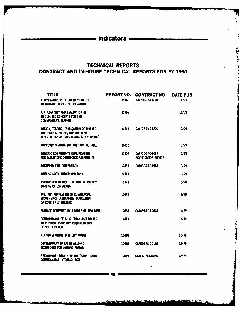
indicators
TECHNICAL REPORTSCONTRACT AND IN-HOUSE TECHNICAL REPORTS FOR FY 1980
TITLE REPORT NO. CONTRACT NO DATE PUB.TEMPERATURE PROFILES OF VEHICLES 12443 DAAK30-77-A-04 10/79IN DYNAMIC MODES OF OPERATION
AIR FLOW TEST AND EVALUATION OF 12452 10/79NBC SHIELD CONCEPTS FOR XMICOMMANDER'S STATION
DESIGN, TESTING, FABRIATION OF MOLDED 12211 DAAE07-75-C-0276 10/79NEOTHANE CUSHIONS FOR THE M151,M715, M35A7 AND 800 SERIES 5-TON TRUCKS
IMPROVED SEATING FOR. MILITARY VEHICLES 12430 10/79
GENERIC COMPONENTS QUALIFICATION 12457 DAAK30-77-C,087 10/79FOR DIAGNOSTIC CONNECTOR ASSEMBLIES MODIFICATION P00002
RECAPPED TIRE COMPARISON 12451 DAAK30-78-C-084 10/79
JOINING STEEL ARMOR INTERMIX 12311 10/179
PRODUCTION METHOD FOR HIGH EFFICIENCY 12383 10/79JOINING OF ESR ARMOR
MILITARY ADAPTATION OF COMMERCIAL 12442 11/79ITEMS (MACI) LABORATORY EVALUATIONOF CODE E-417 ENGINES
SURFACE TEMPERATURE PROFILE OF M60 TANK 12454 DAAK39-77-A4O4 11/79
CONFORMANCE OF T-132 TRACK ASSEMBLIES 12473 11/79TO PHYSICAL PROPERTY REQUIREMENTSOF SPECIFICATION
PLATFORM FIRING STABILITY MODEL 12459 11/79
DEVELOPMENT OF LASER WELDING 12455 DAAK30-78-C.0118 12/79TECHNIQUES FOR JOINING ARMOR
PREUMINARY DESIGN OF THE TRANSITIONAL 12469 DMAE07.76-C.006 12/79CONTROLLABLE INTERFACE SO
,2
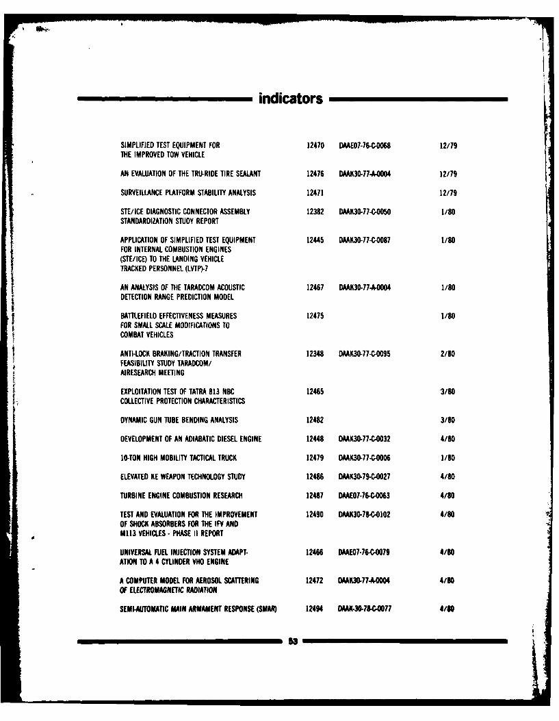
indicators
SIMPLIFIED TEST EQUIPMENT FOR 12470 DAAE07-76-CB068 12/79THE IMPROVED TOW VEHICLE
AN EVALUATION OF THE TRU-RIDE TIRE SEALANT 12476 DAAK30-77-A-O004 12/79
SURVEILLANCE PLATFORM STABILITY ANALYSIS 12471 12/79
STE/ICE DIAGNOSTIC CONNECTOR ASSEMBLY 12382 DAAK30-77-C-O05O 1/80STANDARDIZATION STUDY REPORT
APPLICATION OF SIMPLIFIED TEST EQUIPMENT 12445 DAAK30-77-C-O087 1/80FOR INTERNAL COMBUSTION ENGINES(STE/ICE) TO THE LANDING VEHICLETRACKED PERSONNEL (LVTP)-7
AN ANALYSIS OF THE TARADCOM ACOUSTIC 12467 DAAK30-77-A-0004 1/80DETECTION RANGE PREDICTION MODEL
BATTLEFIELD EFFECTIVENESS MEASURES 12475 1/80FOR SMALL SCALE MODIFICATIONS TOCOMBAT VEHICLES
ANTI-LOCK BRAKING/TRACTION TRANSFER 12348 DAAK30-77-C-O095 2/80FEASIBILITY STUDY TARADCOM/AIRESEARCH MEETING
EXPLOITATION TEST OF TATRA 813 NBC 12465 3/80COLLECTIVE PROTECTION CHARACTERISTICS
DYNAMIC GUN TUBE BENDING ANALYSIS 12482 3/80
DEVELOPMENT OF AN ADIABATIC DIESEL ENGINE 12448 DAAK30-77-C-0032 4/80
10-TON HIGH MOBILITY TACTICAL TRUCK 12479 DAAK30-77C-O006 1/80
ELEVATED KE WEAPON TECHNOLOGY STUDY 12486 DAAK30-79-C-O027 4/80
TURBINE ENGINE COMBUSTION RESEARCH 12487 DAAE07-76-C063 4/80
TEST AND EVALUATION FOR THE IMPROVEMENT 1240 DAAK30-78-C-O102 4/80OF SHOCK ABSORBERS FOR THE IFV ANDM113 VEHICLES- PHASE II REPORT
UNIVERSAL FUEL INJECTION SYSTEM ADAPT- 12466 DAAE07-76-.C079 4/80ATION TO A 4 CYLINDER VHO ENGINE
A COMPUTER MODEL FOR AEROSOL SCATTERING 12472 DAAK30-77-A-OO04 4/80
OF ELECTROMAGNETIC RADIATION
SEMI-AUTOMATIC MAIN ARMAMENT RESPONSE (SMAR) 12494 DAAK-3S-78,-C077 4/80
-3
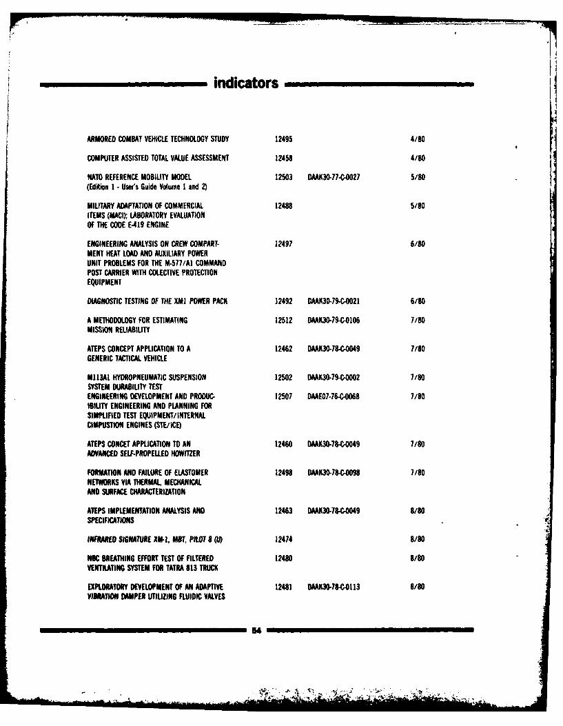
indicators -
ARMORED COMBAT VEHICLE TECHNOLOGY STUDY 12495 4/80
COMPUTER ASSISTED TOTAL VALUE ASSESSMENT 12458 4/80
NATO REFERENCE MOBILITY MODEL 12503 DAAK30-77-C-0027 5/80(Edtion I -Users Guide Volume I and 2)
MILITARY ADAPTATION OF COMMERCIAL 12488 5/80ITEMS (MACI); LABORATORY EVALUATIONOF THE CODE E-419 ENGINE
ENGINEERING ANALYSIS ON CREW COMPART- 12497 6/80MENT HEAT LOAD AND AUXILIARY POWERUNIT PROBLEMS FOR THE M-577/Al COMMANDPOST CARRIER WITH COLECTIVE PROTECTIONEQUIPMENT
DIAGNOSTIC TESTING OF THE XMI POWER PACK 12492 DAAK3-79-C-0021 6/80
A METHODOLOGY FOR ESTIMATING 12512 DAAK30-79-C-01D6 7/80MISSION RELIABILITY
ATEPS CONCEPT APPLICATION TO A 12462 DAAK30-78-C-0049 7/80GENERIC TACTICAL VEHICLE
U113AI HYDROPNEUMATIC SUSPENSION 12502 DAAK3-9-C-0002 7/SOSYSTEM DURABILITY TESTENGINEERING DEVELOPMENT AND PRODUC- 12507 DAAE07-76-C-0068 7/80ISIL1TY ENGINEERING AND PLANNING FORSIMPLIFIED TEST EQUIPMENT/ INTERNALCIMPUSTION ENGINES (STE/ICE)
ATEPS CONCET APPLICATION TO AN 12460 DAAK30.78-C,0049 7/80ADVANCED SELF-PROPELLED HOWITZER
FORMATION AND FAILURE OF ELASTOMER 12498 DAAK30-78-C-0098 7/80NETWORKS VIA THERMAL, MECH4ANICALAND SURFACE CHARACTERIZATION
ATEPS IMPLEMENTATION ANALYSIS AND 12463 DAAK30-C4,049 8/80SPECIFICATIONS
INFRARED SIGNATURE XM-l, MO, PILOT 8 (U)) 12474 8/80
NBC BREATHING EFFORT TEST OF FILTERED 12480 8/80VENTILATING SYSTEM FOR TATRA 813 TRUCK
EXPLORATORY DEVELOPMENT OF AN ADAPTIVE 12481 DAAK30-78-C113 8/80VIBRATION OWMER UTILIZING FLUIDIC VALVES
54IIIIIII
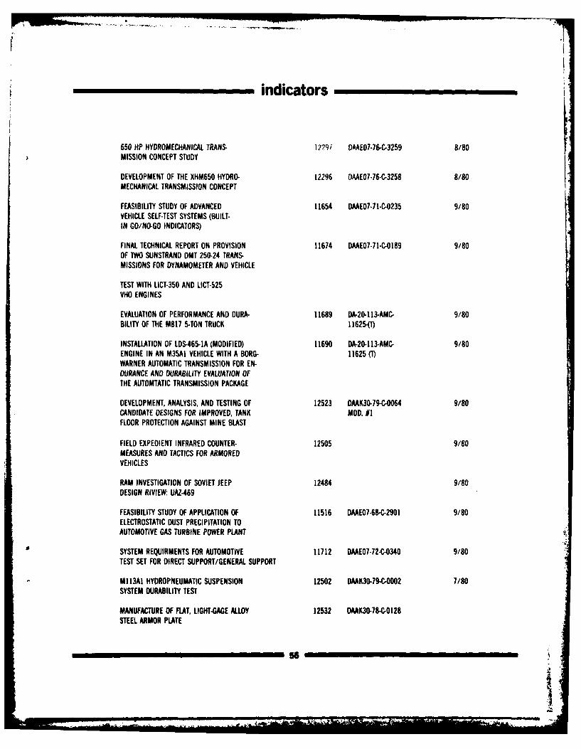
indicators
650 HP HYDROMECHANICAL TRANS- 1279i DAAE07-76-C-3259 8/80MISSION CONCEPT STUDY
DEVELOPMENT OF THE XHM650 HYDRO. 12296 OAAE07-76-C-3258 8/80MECHANICAL TRANSMISSION CONCEPT
FEASIBILITY STUDY OF ADVANCED 11654 DAAE07-71-C-0235 9/80VEHICLE SELF-TEST SYSTEMS (BUILT-IN GO/NO-GO INDICATORS)
FINAL TECHNICAL REPORT ON PROVISION 11674 DAAE07-71-C-0189 9/80OF IWO SUNSTRAND DMT 250-24 TRANS-MISSIONS FOR DYNAMOMETER AND VEHICLE
TEST WITH LICT-350 AND LICT-525VHO ENGINES
EVALUATION OF PERFORMANCE AND DURA- 11689 DA-20-113-AMC- 9/80BILITY OF THE M817 5-TON TRUCK 11625-1)
INSTALLATION OF LDS-465-IA (MODIFIED) 11690 DA-20-113-AMC- 9/80ENGINE IN AN M35A1 VEHICLE WITH A BORG- 11625 (T)WARNER AUTOMATIC TRANSMISSION FOR EN-OURANCE AND DURABILITY EVALUATION OFTHE AUTOMTATIC TRANSMISSION PACKAGE
DEVELOPMENT, ANALYSIS, AND TESTING OF 12523 DAAK30-79-C-0064 9/80CANDIDATE DESIGNS FOR IMPROVED, TANK MOD. 1FLOOR PROTECTION AGAINST MINE BLAST
FIELD EXPEDIENT INFRARED COUNTER- 12505 9/80MEASURES AND TACTICS FOR ARMOREDVEHICLES
RAM INVESTIGATION OF SOVIET JEEP 12484 9/80DESIGN RIVIEW UAZ-469
FEASIBILITY STUDY OF APPLICATION OF 11516 DAAE07-68-C-2901 9/80ELECTROSTATIC DUST PRECIPITATION TOAUTOMOTIVE GAS TURBINE POWER PLANT
SYSTEM REQUIRMENTS FOR AUTOMOTIVE 11712 DAAE07-72-C-0340 9/80TEST SET FOR DIRECT SUPPORT/GENERAL SUPPORT
M]13AI HYDROPNEUMATIC SUSPENSION 12502 DAAK30-79-C-O002 7/80SYSTEM DURABILITY TEST
MANUFACTURE OF FLAT, LIGHT-GAGE ALLOY 12532 DAAK30-78-C-0128STEEL ARMOR PLATE
i ii ii 56
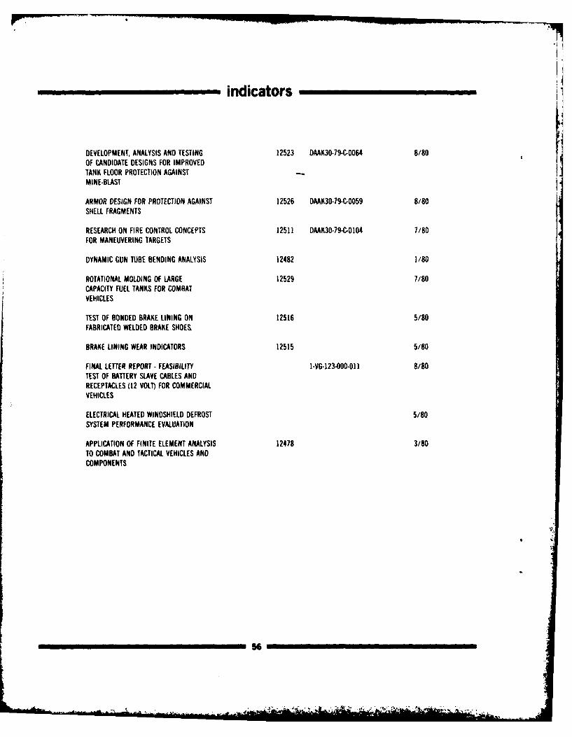
indicators
DEVELOPMENT, ANALYSIS AND TESTING 12523 DAAK30-79-C-0064 8/80OF CANDIDATE DESIGNS FOR IMPROVEDTANK FLOOR PROTECTION AGAINSTMINE-BLAST
ARMOR DESIGN FOR PROTECTION AGAINST 12526 DAAK30-79-C-0059 8/80SHELL FRAGMENTS
RESEARCH ON FIRE CONTROL CONCEPTS 12511 DAAK30-79-C-0104 7/80FOR MANEUVERING TARGETS
DYNAMIC GUN TUBE BENDING ANALYSIS 12482 1/80
ROTATIONAL MOLDING OF LARGE 12529 7/80CAPACITY FUEL TANKS FOR COMBATVEHICLES
TEST OF BONDED BRAKE LINING ON 12516 5/80FABRICATED WELDED BRAKE SHOES,
BRAKE LINING WEAR INDICATORS 12515 5/80
FINAL LETTER REPORT - FEASIBILITY I-VG-123-O00-O 1 8/80TEST OF BATTERY SLAVE CABLES ANDRECEPTACLES (12 VOLT) FOR COMMERCIALVEHICLES
ELECTRICAL HEATED WINDSHIELD DEFROST 5/80SYSTEM PERFORMANCE EVALUATION
APPLICATION OF FINITE ELEMENT ANALYSIS 12478 3/80TO COMBAT AND TACTICAL VEHICLES ANDCOMPONENTS
56
facilities
FACILITIES
anechoic chamber. Cell 9 is equipped for track- handle vehicles up to 60 tons. The experimentalOVERVIEW ed or wheeled vehicle tests under temperatures foundry, model and pattern shop, heat treating,up to 1600 F, solar radiation simulation, and plating and painting equipment complete thThe U.S. Army Tank-Automotive R&D Command winds up to 20 mph. fabrication complex.
Laboratories and shops are equipped to developand support the military vehicle fleet. Researchand study are performed here on propulsion TRACK AND SUSPENSION ELECTRO-MECHANICALsystems, surface mobility systems, vehicularcomponents, and materials - from concept LAB SYSTEMSthrough prototype. Replacement cost of thesefacilities in today's dollars is $158,000,000. One of the outstanding features of this Additional facilities permit test of engine ac-laboratory is its dynamic simulation capability. cessories - including tank air cleaners, elec-
Vibration and shock imputs from terrain tapes trical components, and mechanical andPHYSICAL SCIENCE LAB are fed through hydraulic actuators to the tires, hydraulic subsystems.
wheel spindles or roadwheel arms. The simula-•1he lab has facilities for extensive investigations tion approaches permit accelerated testing ofinto vehicle signatures and signature reduction vehicles and components so that designs can be KEWEENAW FIELD STATIONmethods. Non-destructive test capabilities in- optimized without time consuming field testing.clude holographic analysis. Mini-computers and Smaller actuators accommodate fatigue tests on The Keweenaw Field Station is located atremote terminals provide a ready capability for components and subsystems Houghton, MI and consists of vehicleengineering analysis, modeling, and simulation maintenance shops, small machine shop storage,studies. and office buildings; it houses a wide variety of
EXPERIMENTAL support vehicles and equipment for R&D fieldFABRICATION testing. The station is managed by the Ke-
PROPULSION SYSTEMS LAB weenaw Research Center of the MichiganThe facility includes sheet metal, welding, Technological University and is used for a wide
Present facilities include nine test cells. Three machining equipment capable of fabricating variety of R&D work as well as related field testsare vehicle or transmission cells and six are for steel or aluminum hulls and turrets. The in support of TARADCOM's mission.
engines. One cell is equipped with a semi- assembly area has high bays and cranes to
Edite aid cordiniated
by Richard C, Sarikeroiect Officr forthe Posture Report
kUntioes to improe iehe MW we welcome. Reqotso fw copes may be addretsd toTechnical iibry Office. DRSTA-TS U.S Army TailAte'striat Commnid, WanM..Michiqa. 48190.
57
'

1


![Clase 2 . Huesos MMSS II[1]](https://img.pdfslide.net/doc/110x75/55cf919f550346f57b8f05d1/clase-2-huesos-mmss-ii1.jpg)