Embed Size (px)
Citation preview

1
Porous materials
2
Porous materials
Classically porous materials are organic materials, polymeric foams…A large number of inorganic porous materials have been developed, e.g. for insulation, cushioning, impact protection, catalysis, membranes, construction materials…
• Materials with different pore sizes (from nanometer to millimeter)• Ordered or irregular arrangement of pores• Various chemical compositions (metal, oxides…)• Different preparative approaches.

3
Porosity
Porous: Contain pores (cavities, channels, interstices) which are deeper than they are wide.
Either describe the pores, or describe the cell/pore walls
Accessibility:a: closed poresb,c,d,e,f: open poresb, f: blind pores (dead-end or saccate)e: through poresShape:c:Cylindrical openf:Cylindrical blindb: ink-bottle-shapedd: funnel shapedg: roughness
4
Some definitions

5
Measuring porosity
The measured value depends on the method.Some detects only open pores, e.g. adsorption of molecules.(Open pore and accessibility is then defined by the probe molecule)Other may probe also closed pores, e.g. spectroscopy, diffraction, scattering.
6
Pore sizePore size is important for applications.IUPAC, three pore size regimes, associated with transport mechanisms:
•Microporous, smaller than 2 nm•Mesoporous, between 2 and 50 nm•Macroporous, larger than 50 nm
Macropores: larger than typical mean free path length of typical fluid. Bulk diffusion and viscous flow.
Mesopores: same order or smaller than the mean free path length. Knudsen diffusion and surface diffusion. Multilayer adsorption and capillary condensation ay contribute.
Micropores: pore size comparable to the molecules. Activated transport dominates.

7
Metallic foams and porous metals
May be seen as composite materials consisting of a solid and a gaseous phase.Porous metals: high bulk density, independent, distributed voidsMetallic foams: Low bulk density, interconnected voids.Porosity: 30-98 vol% (pore volume/apparent volume, VP/V)
Impact energy adsorption, air and water permeability, acoustical properties, low thermal conductivity.
Energy absorbing systems, porous electrodes, sound absorbers, filters, insulating materials, heat exchangers, construction materials, electromagnetic shielding, membrane and membrane support.
8
Metallic foam production

9
Casting techniques
Foaming: a blowing agent (e.g. a metal hydride) is added to the molten metal. Decomposition creates gas, which expands and foams the metal.Difficulties: to obtain small bubbles distributed uniformly throughout the material.High speed mixing, viscosity increasing agents.High porosity, 60-97%, Closed-cell materials.
10
“Lost-foam casting”
Organic foam is filled by an inorganic castable material, e.g. gypsum.Combustion of organics result in porous inorganic material.This is used as a mold for the metal (solidified in pores)The inorganic matrix is then removed selectively.
Used e.g. for low melting metals and alloys, e.g. Cu, Al, Pb, Sn, Zn
Up to 95% porosity

11
Porous gold
12
InfiltrationCasting metal around densely packed granular material (template)Interconnected sponge-like materials are obtained, porosity ca. 70%The template materials should be soluble, but heat resistant. E.g. sodium chloride, expanded clays, glass spheres, hollow corundum spheres…
Hollow spheres
Alternatively: stirring of granular materials into the melt.

13
Gas-eutectic transformation
Mainly metal-hydrogen systems based on saturating the molten metal with gas.
1. Charging the melt with hydrogen to reach the eutectic composition2. Solidification of the melt, whereby the saturated melt decomposes into a
solid and a gas phase.
No foaming is observed, gas evolution as the metal solidifies.
Process parameters: hydrogen level in the melt, gas pressure above the melt,direction and rate of heat removal, chemical composition.Porosity ca. 70%, pore size 10 μm – 10 mm
Gasars. (abbreviation of the Russian term for gas-reinforced.)
14
Cu and Mg gasars
V. Shapovolov and L. Boyko,Adv. Eng. Mater. 2004, 407

15
Powder metallurgy
Powder sintering or loose powder sintering:Fill the loose powder into a form and heat. Sintering by forming contacts between grains. Porous metals formed, porosity 40-60%.Pore forming or spacing agents may be added. Decompose or evaporate during sintering. May give porosities of 90%.
Sintering of hollow spheres:Hollow spheres are close packed and pre-sinteredMetal powder is filled into the voids, and the final sintering is done.
16
Fiber metallurgyMetal fibers are used instead of powder.•The porosity may be controlled from 0-95vol%, while maintaining constructional properties.•High strength and ductility may be obtained.
Metal fibers are produced e.g. by machining or drawing.Compacted and sinteredMay be coated by a low-melting agent to improve bonding.The structure may be ordered or randomly oriented.

17
Metal deposition
CVD, electrochemical, PVD methods may be used.
Electrochemically deposited on porous organic substrates. (ca. 90% porous)PVD on cold substrate, which is then removed (up to 95% porosity)
Porous silicon by anodization. Si-wafer in a solution of hydrofluoric acid, ethanol and water. Anodized for a short time using an electric current. Interconnected network of pores, ca. 10nm. The density is 1/10 of silicon, but the material is crystalline.
18
Aerogels
Supercritical drying of a gel.Pores in the mesoporous range, 2-50 nm.Built from e.g. nanometer sized silica spheres forming a three dimensional network. Bulk densities 0.004 – 0.5 g/cm3. (Air: 0.00129 g/cm3)

19
Drying
20
Supercritical drying
A supercritical fluid is a gas, not a vapour.
Supercritical drying; follow the path 1-2-3-4-5.

21
22
Ambient pressure drying
Capillary forces are the main reason for collapse of the gel during drying.Solutions:Strengthen the networkand/orModify the contact angle between liquid and solid. (modifying the surface and variation of solvent properties)
Exchange the solvent with a water free solvent.Silylate the Si-OH group (e.g. by chlorotrimethylsilane) (hydrophobic)Wash and dry.Shrink, then expand (spring-back)

23
Applications
STARDUST
24
Porous solids with an ordered porosity
Templating approach to ordered porous solids: pores are arranged in a regular pattern with a narrow pore size distribution.Zeolites: microporousMCM /M41S) materials: mesoporous
Synthesis
Drying
Template removal

25
Microporous crystalline solids
Microporous inorganic solids:ZeolitesZeotypes(microporous aluminophosphates, chlatrasils…)
CatalystsMolecular sievesSorptionIon exchange
26
Natural zeolites

27
Zeolites
Zeolites are porous, hydrated aluminosilicates. They may be natural minerals or synthetic materials.
The general chemical composition of a zeolite is:
Mnx/nSi1-xAlxO2 · yH2O
Where M = e.g. Na+, K+, Li+, Ag+, NH4+, H+, Ca2+, Ba2+…
Characteristics of zeolites:
1) Tectosilicates, i.e. three dimensional structure built from tetrahedra. Some silicon atoms have been replaced by aluminium, i.e. the (Si+Al)/O = ½. (Tetrahedrausually denoted T-atoms.
2) Open framework structure built from TO4-tetrahedra, containing pores and voids. The structure and porosity is periodic (i.e. crystalline materials). The pores have molecular dimensions.
28
3) Counter ions (cations) are present in order to compensate for the negative framework charge created by aluminium substitution. The counter ions are situated in the pores and voids, and are usually mobile.
4) In the voids and pores are also water molecules (zeolitic water). One measure of the porosity is the amount of adsorbed water. The water molecules are also present in the pores and voids, and may (in many cases) be removed by heating and readsorbed at lower temperatures.
5) Loewensteins rule imposes a limit to the amount of aluminium which may be substituted into the framework: No Al-O-Al may be present in tectosilicates. This means that only half of the silicon atoms may be substituted by aluminium. For the general composition:
Mnx/nSi1-xAlxO2 · yH2O
This means that the Si/Al ratio is larger than 1 and that x is smaller than 0.5This rule is not always obeyed! (High aluminium e.g. Si/Al = 0.5)High silica and pure silica zeolites have been synthesised
Zeolites

29
Microporous zeolite-like materials
Aluminophosphates, AlPO’s III-V analogues of SiO2: AlPO4
E.g. Berlionite structurally similar to α-quartz
Microporous aluminophosphates (Flannigan, Union Carbide)
AlPO4: Neutral frameworkSynthesis at acidic conditionsMore than 40 aluminophosphate based structures. Mainly alternating Al,P, i.e. no 5-ring structures…
Substitution of atoms with different valence into the framework creates lattice charge, important especially for use as catalysts:
SAPO: silicon substituted ALPOMePO: Metal substituted aluminophosphatesMeAPSO: Metal substituted silicoaluminophosphates
Divalent cations which can adopt tetrahedral geometry, e.g. Mg2+, Mn2+, Fe2+, Co+2, Zn2+.SAPO: Silicon substitutes only for P, e.g. HxSixAlP1-xO4
MAPO: divalent cations substitutes only for Al, i.e. HxMxAl1-xPO4
MeAPSO: e.g.. Hx+y(SixMeyAl1-yP1-z)O4
30
Adsorption (molecular sieve)
Adsorption in zeolites is significantly different from adsorption in e.g. silica gel or active coal, which have a broad size distribution of pore sizes, and where the size of the pores are in the range of 10 nm.In zeolites the porosity is determined by the crystalline structure, i.e. the pores are arrnged in a regular fashion with only one (or a few) discrete pore sizes. Also the pores have molecular dimensions.
The implication of this is the use of zeolites as adsorbants and molecular sieves.
Mainly used for water adsorption (very low equilibrium water vapour pressure)Gas (hydrogen?) storage materials
Molecular sieving effect due to size limitation imposed by framework structure and cation size and position.
Also weaker interactions: N2-O2 separation

31
Ion exchange (ionic conductivity)
The counter-cations in zeolites are mobile, and may easily be exchanged.
This results in ion exchange capability utilized e.g. in detergents and in waste water purification. Or pigs food…
Swine Rese
arch Shows
Incre
ased G
rowth R
ateZAR-M
IN®
Swine Research
32
Catalysis
One of the major uses of zeolites is as heterogeneous catalysts in the petrochemical industry. Cracking catalysts (H-form of zeolite Y, faujasite) is the largest use of zeolites.
They are used also e.g. for production of synthetic gasoline (ZSM-5) from methanol, and synthesis of fine chemicals.
Zeolite catalysts give high selectivity (shape selective) and their properties may be tailored by changing the chemistry, e.g. Si/Al ratio, and counter cations.

33
Atlas of Zeolite Framework Types
ZONYUG-WENWEIVSVVNIVFIVETUTLUSIUOZ
UFIUEITSCTONTHOTERSTTSTISTFSSYSOSSOD
SGTSFOSFNSFHSFGSFFSFESBTSBSSBESAVSAT
SASSAORWYRWRRUTRTHRTERSNRRO-RONRHOPON
PHIPAU-PAROWEOSOOSIOFFOBWNSINPONONNES
NATNABMWWMTWMTTMTNMTFMSOMOZMORMONMFS
MFIMERMEPMELMEIMAZMARLTNLTLLTALOVLOS
-LITLIOLEVLAUKFIJBWIWWIWRITWITHITEISV
IHWIFRHEUGOOGONGMEGIUGISFRAFERFAUEUO
ETRESVERIEPIEONEMTEDIEABDONDOHDFTDFO
DDRDACCZPCON-CLO-CHICHACGSCGFCFICDOCAS
CANBREBPHBOGBIKBEC*BEABCTAWWAWOATVATT
ATSATOATNASVASTAPDAPCANAAHTAFYAFXAFT
AFSAFRAFOAFNAFIAFGAETAENAELAEIACOABW
http://www.iza-structure.org/databases/
34
Zeolite synthesis
The first laboratory synthesis of a zeolite is attributed to Deville, who in 1862 synthesized levyne (levynite) Ca9 [Al18Si36O108] . 50 H2O by heating potassium silicate and sodium aluminate in a glass ampoule.
A large increase in synthesis of zeolites was seen after 1940 when X-ray diffraction became a common tool for analysis.
Usually synthesized from a basic medium (sol or gel) under mild to medium hard hydrothermal conditions (70-350˚C). Mainly obtained as powder arvery small crystals.
Contains: Water, silica source, alumina source, pH-regulators, templates, (catalysts, nucleation centers…)
http://www.iza-online.org/synthesis/default.htm

35
Parameters:
•Composition•Temperature•pH•temperature ramps•ageing conditions•stirring rate•order of mixing etcetcetcLow silica content
low synthesis temperature, 70-100˚C
More siliceous hydrothermal
36
Zeolite synthesis is still mainly done by trial and error. And some knowledge and experience.
Some rules-of-thumb for zeolite synthesis:

37
TemplatesCations (and hydrated cations) acts as counterions, but also have a templatingeffect. Templates stabilize the open framework by filling the empty space. Added templates, e.g. amines and quaternary ammonium ionsGoal: targeted synthesis of microporous structures by template control.
•Structure directing or templating agent•Gel modifier (e.g. influencing Si/Al ratio)•Void filler•Change the formation and aging of gels•Influence the crystallization process
38
Templates as structure directing agents
Addition of other templates have increased the number of zeolite type structures prepared by leading to hitherto unknown zeolites and other microporous materials.Also, it has made it possible to synthesize zeolites with various Si/Al ratios, e.g. zeolite LTA with a Si/Al ratio > 1.Clearly the template has a structure directing effect. But the templatingeffect is still not understood, and it is not possible to predict which zeolitestructure is produced by a certain template.

39
Combinatorial approach (SINTEF)
40
In-situ studies; understanding nucleation and crystallization in hydrothermal synthesis of microporous materials.

41
Zeolite (zeotype) structure
•The basic (primary) building blocks are tetrahedra•All tetrahedra share corners•The arrangement of the building blocks is periodic (crystalline)
Representation of a six membered ringof TO4-tetrahedra(Contains 6 Si and 6 O)
Building units:•Primary or basic building units (BBU): Tetrahedron•Secondary or composite building units (CBU): polymeric structures (rings, prisms etc.)•Tertiary building units: Larger cages
The flexibility of the T-O-T bond angle (120-180˚) allows a large number of CBUs to exist, and results in a wealth of different structures to be constructed
42
CBUs
Zeolite structures may be seen as built from CBUs. For instance the ZSM-5 framework may be built from 5-1 units.
It is important not to assume that the synthesis of zeotypematerials occur via assembly of CBUs floating around in the synthesis mixture.

43
Rings and pore size
Pore openings or rings in zeolites.8-, 10-, and 12-rings shown as connecting spheres.The openings may have various shapes, influencing the kinetic diameter.
Analcime 8-ring
Edingtonite 8-ring
44
Cages and channelsZeolite LTA. May be seen as built from the CBUs: 8, 4-4, 6-2, 6, 1-4-1, 4May be seen as built from interconnected sodalite cages (β-cages)

45
Linking CBUs, composite building units
cancrinite
46
Dimensionality

47
Metal-organic framework materials (MOFs) Porous three dimensional coordination polymers
Hybrid materials
A new class of ordered microporous materials are the metalorganic framework materials. These are built by linking inorganic parts (connector) (metal ions, clusters…) using organic linkers.
48
Connectors and linkers
• The connectors are mostly transition metal or lanthanoid ions. Coordination number varies. May also be polynuclearclusters.
• The linkers are organic (or inorganic) bi-or multidentate.
• The interaction between connectors and linkers are coordinative or ionic (not covalent as in zeolites)
Popular linkers may contain nitrogen or oxygen donor atoms, e.g. 4,4’-bipyridine, benzene-1,4-dicarboxylate (terephthalate).

49
Synthesis
The variety of different connectors and linkers makes it possible to construct a variety of 1-, 2- and 3-dimensional structures. The design of linkers is especially efficient in attempting to form new structure types.
Standard coordination chemistry methods are used, where metal ions are reacted with an organic ligand. The conditions are low temperature and hydrothermal/solvothermal synthesis.This may be seen as “self-assembly” of basic building units. The products are usually not kinetically but thermodynamically determined.The flexibility/rigidity of the linker is important for the properties, e.g. the possibility of forming porous materials. Most used linker are fairly rigid. Also during formation the rigidity of the linkers are important; a very flexible linker may enable several possible conformations, resulting in poorly crystalline materials.
50
Frameworks
Frameworks obtained by using various connectors linked by linear linkers.
3-D MOF materials are among those with the largest pores for crystalline materials. When synthesized the pores will be filled by guest or template molecules. In order to obtain porosity it is necessary to remove the guest species. This is difficult due to a generally low thermal stability of the materials. (May also fill space by forming e.g. two interpenetrating frameworks).Also exceptionally high surface areas may be obtained. (several thousand square meters per gram)

51
Zn4O(terephthalate) (Yaghi)
Very low density: (0.59g/cm3)
Framework stable up to 300˚C.
Very high surface area.
52
Classification
• 1st generation: The framework is only maintaines with the guest molecules present, and collapses upon removal of the guests.
• 2nd generation: The framework is stable and robust, and have porosity when removing the guest species.
• 3rd generation: the framework is flexible and dynamic and responds to external stimuli.
2nd and 3rd generation materials may be used for gas storage or as catalysts.
Advantages:
• In principle the dimensions and shape of the channels are easily tunable by changing the organic linkers.
• Functionality may be built into the linkers.
• The materials are light weight, making it possible to obtain large surface areas.

53
Mesoporous solids with ordered porosity.
Pore size is important for applications.IUPAC, three pore size regimes, associated with transport mechanisms:
•Microporous, smaller than 2 nm•Mesoporous, between 2 and 50 nm•Macroporous, larger than 50 nm
New development in 1992 by Mobil: ordered mesoporous materials were made by using supramolecular species as templates instead of solvated cations or organic molecules.
Amphiphilic surfactant molecules (lyotropic liquid crystals) were used.•Pore range from 2 to 10 nm.•Large specific surface area•Large pore volume•Monomodal narrow distribution of of pore sizes.
Pore walls are amorphous (not crystalline)
54
M41S
The M41S family are of interest e.g. as catalysts, catalyst supports, adsorbents, host structures for nanometer sized guest compounds.MCM (Mobil Composition of Matter)MCM-41: One dimensional, hexagonal ordered, channel structureMCM-48: Cubic three-dimensional channel structure (bicontinuous)MCM-50: Lamellar two dimensional. Silica layers, surfactant bilayers

55
Synthesis
Ingredients for MCM synthesis:Water, an amphophilic molecule, a soluble inorganic precursor and a catalyst(Why a catalyst??)
Synthesis conditions from -14 to 180˚C.
Synthesis:•Formation of supramolecular arrangement of molecules,•Templating•Removal of template
56
Supramolecular arrangements
e.g. CTAB: cetyltrimethylamonium bromide, CH3(CH2)15N(CH3)3N+Br-
Forms spherical micelles.
Size, extent, shape of micelles and aggregation into liquid crystals depends on the concentration and temperature.
Low concentration: individual moleculesIncreasing concentration:•Small spherical micelles above the micelle concentration (cmc)•Micelles coalesce into elongatede cylindrical micelles•Liquid crystals form at slightly higher concentrations:
•Hexagonal close packed cylinders•Bicontinous cubic arrangement•Lamellar arrangement
•At even higher concentrations inverse phases may exist.
The surfactants may arrange themselves in supramolecular arrays, e.g. micelles.

57
Phase diagrams
58
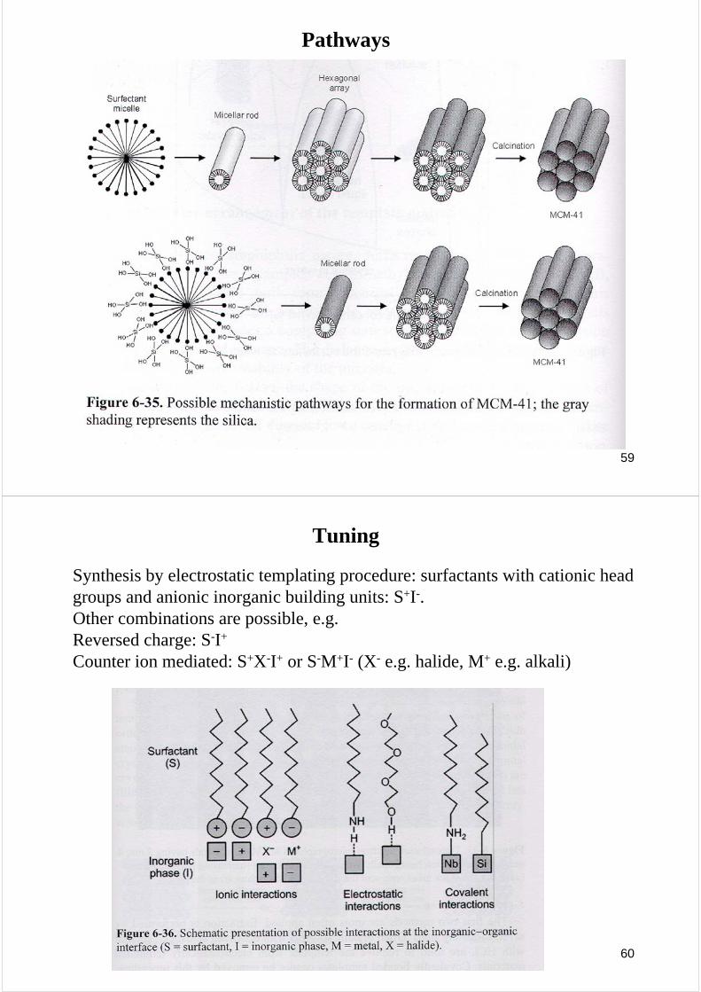
Templating
MCM-41 synthesized under hydrothermal conditions using CTABTwo mechanisms were proposed:
1) Liquid crystal initiated pathway: Organization of the surfactant molecules (independent of the polycondensation). Followed by formation of the siliceous framework around the aggregates,
2) Silicate anion-initiated pathway: The siliceous species associate with the surfactant molecules, and then it organizes into a supramolecular array.
59
Pathways
60
Tuning
Synthesis by electrostatic templating procedure: surfactants with cationic head groups and anionic inorganic building units: S+I-. Other combinations are possible, e.g. Reversed charge: S-I+
Counter ion mediated: S+X-I+ or S-M+I- (X- e.g. halide, M+ e.g. alkali)

61
Removal of template
In order to create porosity the template must be removed.Several different ways are possible:
•Solvent extraction•Calcination•Oxygen plasma treatment•Supercritical drying
Extraction often with organic solvents with dissolved acids. (e.g. EtOH w. HCl)(Cannot remove covalently bonded molecules)Calcination typically at 4-600˚C in e.g. N2 or air.
Framework structures (hexagonal or cubic MCM phases) may survive template removal. Lamellar phases collapse.
Design of mesoporous ordered materials with dieerent pore sizes is possible by tuning the template molecules.Mesoporous materials containing elements other than Si have been produced.
62
MCM-41, TEM images

63
Macroporous solids with ordered porosity
Prepared by e.g. packing of solid materials. (as described with metal foams)
Colloidal crystal packing:1) Colloidal crystal formed by closed packed monodisperse spheres (e.g. latex
or silica) (Similar to Opals)2) The interstitial space is filled with a liquid precursor3) The precursor solidifies4) The template is removed
Inverse replica of the template array (also called inverse opal)
64
Opals and inverse opals

65
Spheres
Stöber process: TEOS is reacted at high pH (ammonia solution) with large excess of water. Monodisperse silica spheres between 0.1 and 1 μm.
Spheres for packing into either fcc or hcp. Requirements:•The template must be removable•Must be compatible with process conditions•The precursor solution must wet the particles•Must have a narrow size distribution.
Narrow it down to two classes:•Silica spheres prodused by the Stöber process (50 nm – 2 μm)Organic polymer spheres produced from emulsion polymerization.
66
Impregnating
Impregnating with a low viscodity liquid, solutions, dispersions.Metal alkoxides, molten metals, salt solutions, colloidal gold nanoparticles, vapours (Precursors for CVD)
Removal of the template by extraction (e.g. HF for silica) or calcination (may be simultaneous with the solidification step)

67
Functional groups incorporated into porous materials
Functionalizing porous materials is important for many applications.
Functionalization may be done by introducing guest species in the pores, attached to the walls or by building functionality into the walls.
E.g. dyes or biomolecules, catalysts, optical active molecules, functional organic groups (e.g. adsorption)…
Molecules may be introduced by adsorption, by co-synthesis (templates), “ship-in-a-bottle” synthesis, condensation (covalently attached) by grafting, or co-condensation.
68
PMO: Periodic Mesoporous Organosilica