Embed Size (px)
Citation preview
Bauhaus Summer School in Forecast Engineering: Global Climate change and the challenge for built environment
17-29 August 2014, Weimar, Germany
Dynamic properties of multistory reinforced concrete tunnel-form
building - a case study in Osijek, Croatia
KLASANOVIĆ, Ivana
Graduate student, Faculty of Civil Engineering, Osijek, Croatia, [email protected]
KRAUS, Ivan
PhD student, Faculty of Civil Engineering, Osijek, Croatia, [email protected]
HADZIMA-NYARKO, Marijana
Assistant Professor, Faculty of Civil Engineering, Osijek, Croatia, [email protected]
Abstract
Reinforced concrete shear wall (RCSW) dominant buildings, constructed using a special tunnel-form
technique, are commonly built in the Republic of Croatia. The fundamental period of vibration plays a
major role in predicting the expected behavior of structures under dynamic excitations. Empirical
formulas for the estimation of the fundamental period have been included in seismic codes, which
mainly depend on building height, material (steel, reinforced concrete (RC)) and structural systems
type (frame, shear wall, etc.). These formulas have been usually derived from empirical data through
regression analysis of the measured fundamental period of existing buildings subjected to seismic
actions. The main purpose of this paper is to compare the fundamental period obtained from numerical
analysis of a real RC building constructed using a special tunnel-form technique with the periods
obtained using formulas in different building codes.
1. Introduction
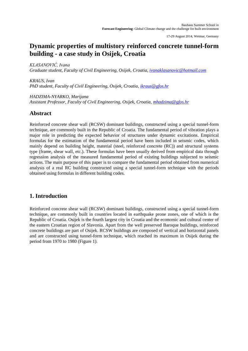
Reinforced concrete shear wall (RCSW) dominant buildings, constructed using a special tunnel-form
technique, are commonly built in countries located in earthquake prone zones, one of which is the
Republic of Croatia. Osijek is the fourth largest city in Croatia and the economic and cultural center of
the eastern Croatian region of Slavonia. Apart from the well preserved Baroque buildings, reinforced
concrete buildings are part of Osijek. RCSW buildings are composed of vertical and horizontal panels
and are constructed using tunnel-form technique, which reached its maximum in Osijek during the
period from 1970 to 1980 (Figure 1).
KLASANOVIĆ, Ivana, KRAUS, Ivan, HADZIMA-NYARKO, Marijana / FE 2014 2
Figure 1. Osijek's city block (Sjenjak) built using tunnel-form technique
(http://www.skyscrapercity.com/showthread.php?p=53750153)
The main purpose of this paper is to compare the fundamental period obtained from numerical
analysis of a real RCSW building (Figure 2) located in Osijek’s city block named Sjenjak with the
periods obtained using formulas in European code EC8 (CEN 2004) and other available literature.
Numerical modal analysis will be performed using SAP2000 software (SAP2000, structural analysis
program, Version 16.1.0., 2014) in order to determine the vibration modes.
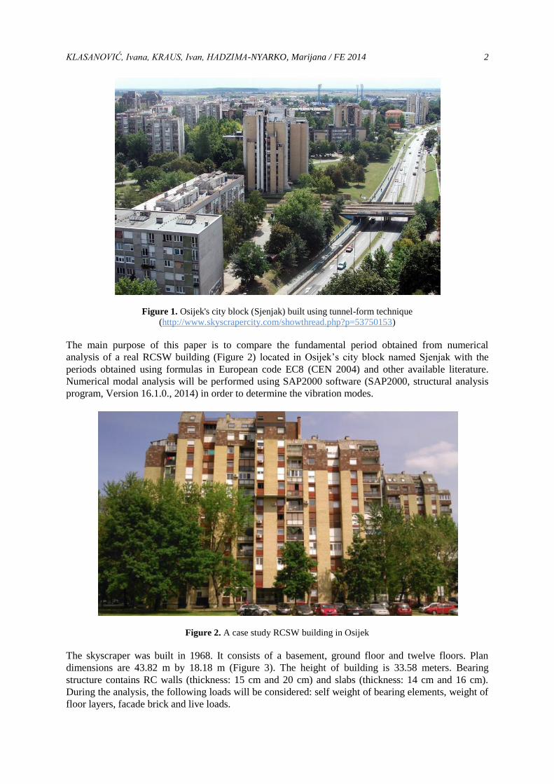
Figure 2. A case study RCSW building in Osijek
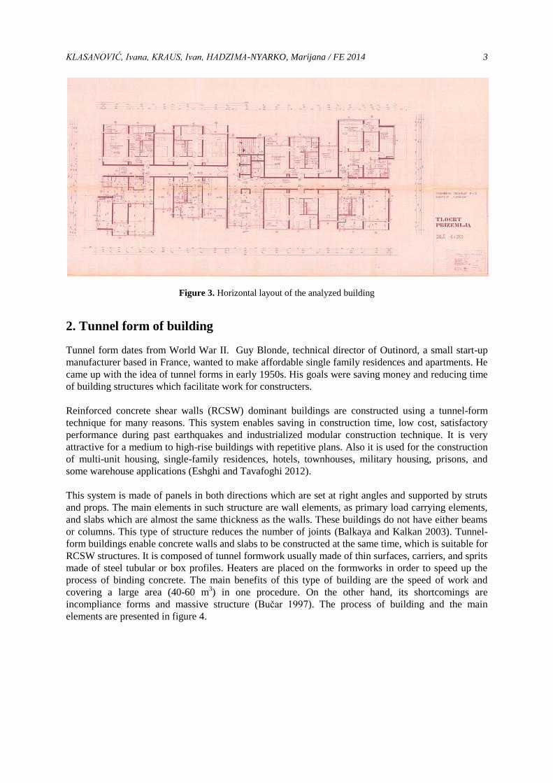
The skyscraper was built in 1968. It consists of a basement, ground floor and twelve floors. Plan
dimensions are 43.82 m by 18.18 m (Figure 3). The height of building is 33.58 meters. Bearing
structure contains RC walls (thickness: 15 cm and 20 cm) and slabs (thickness: 14 cm and 16 cm).
During the analysis, the following loads will be considered: self weight of bearing elements, weight of
floor layers, facade brick and live loads.
KLASANOVIĆ, Ivana, KRAUS, Ivan, HADZIMA-NYARKO, Marijana / FE 2014 3
Figure 3. Horizontal layout of the analyzed building
2. Tunnel form of building
Tunnel form dates from World War II. Guy Blonde, technical director of Outinord, a small start-up
manufacturer based in France, wanted to make affordable single family residences and apartments. He
came up with the idea of tunnel forms in early 1950s. His goals were saving money and reducing time
of building structures which facilitate work for constructers.
Reinforced concrete shear walls (RCSW) dominant buildings are constructed using a tunnel-form
technique for many reasons. This system enables saving in construction time, low cost, satisfactory
performance during past earthquakes and industrialized modular construction technique. It is very
attractive for a medium to high-rise buildings with repetitive plans. Also it is used for the construction
of multi-unit housing, single-family residences, hotels, townhouses, military housing, prisons, and
some warehouse applications (Eshghi and Tavafoghi 2012).
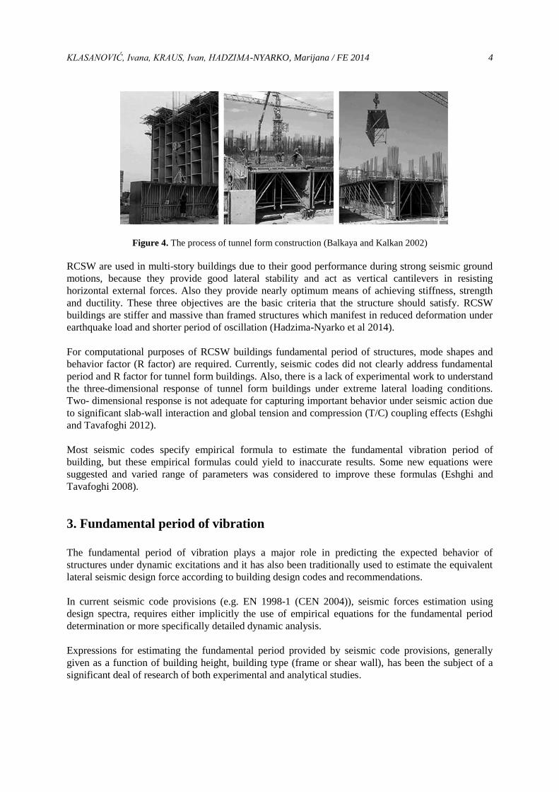
This system is made of panels in both directions which are set at right angles and supported by struts
and props. The main elements in such structure are wall elements, as primary load carrying elements,
and slabs which are almost the same thickness as the walls. These buildings do not have either beams
or columns. This type of structure reduces the number of joints (Balkaya and Kalkan 2003). Tunnel-
form buildings enable concrete walls and slabs to be constructed at the same time, which is suitable for
RCSW structures. It is composed of tunnel formwork usually made of thin surfaces, carriers, and sprits
made of steel tubular or box profiles. Heaters are placed on the formworks in order to speed up the
process of binding concrete. The main benefits of this type of building are the speed of work and
covering a large area (40-60 m3) in one procedure. On the other hand, its shortcomings are
incompliance forms and massive structure (Bučar 1997). The process of building and the main
elements are presented in figure 4.
KLASANOVIĆ, Ivana, KRAUS, Ivan, HADZIMA-NYARKO, Marijana / FE 2014 4
Figure 4. The process of tunnel form construction (Balkaya and Kalkan 2002)
RCSW are used in multi-story buildings due to their good performance during strong seismic ground
motions, because they provide good lateral stability and act as vertical cantilevers in resisting
horizontal external forces. Also they provide nearly optimum means of achieving stiffness, strength
and ductility. These three objectives are the basic criteria that the structure should satisfy. RCSW
buildings are stiffer and massive than framed structures which manifest in reduced deformation under
earthquake load and shorter period of oscillation (Hadzima-Nyarko et al 2014).
For computational purposes of RCSW buildings fundamental period of structures, mode shapes and
behavior factor (R factor) are required. Currently, seismic codes did not clearly address fundamental
period and R factor for tunnel form buildings. Also, there is a lack of experimental work to understand
the three-dimensional response of tunnel form buildings under extreme lateral loading conditions.
Two- dimensional response is not adequate for capturing important behavior under seismic action due
to significant slab-wall interaction and global tension and compression (T/C) coupling effects (Eshghi
and Tavafoghi 2012).
Most seismic codes specify empirical formula to estimate the fundamental vibration period of
building, but these empirical formulas could yield to inaccurate results. Some new equations were
suggested and varied range of parameters was considered to improve these formulas (Eshghi and
Tavafoghi 2008).
3. Fundamental period of vibration
The fundamental period of vibration plays a major role in predicting the expected behavior of
structures under dynamic excitations and it has also been traditionally used to estimate the equivalent
lateral seismic design force according to building design codes and recommendations.
In current seismic code provisions (e.g. EN 1998-1 (CEN 2004)), seismic forces estimation using
design spectra, requires either implicitly the use of empirical equations for the fundamental period
determination or more specifically detailed dynamic analysis.
Expressions for estimating the fundamental period provided by seismic code provisions, generally
given as a function of building height, building type (frame or shear wall), has been the subject of a
significant deal of research of both experimental and analytical studies.
KLASANOVIĆ, Ivana, KRAUS, Ivan, HADZIMA-NYARKO, Marijana / FE 2014 5
3.1 Empirical formulae given by building codes
As mentioned in the previous section, empirical formulas are one of two options to assume a
fundamental period of vibration. In this paper, formulas from three different authors were used in
order to assume a fundamental period of vibration as accurately as possible.
3.1.1 Empirical formulae according to Eurocode 8 (CEN 2004)
According to European code EN1998-1(CEN 2004) the fundamental period could be approximated if
the high of building does not exceed the limit of 80 meters. The expression is:
75.0t HCT ,
(1)
where T is the fundamental period of vibration of the structure (s), H is the height of the structure
(meters) and Ct is a numerical value obtained from measured periods of vibration from structures after
the earthquake in San Fernando in 1971.
This form of expression is obtained with theoretical derivation using Rayleigh’s method with the following assumptions:
a) Equivalent static lateral forces are distributed linearly over the height of the structure;
b) Distribution of the stiffness along the height is made such that the interstory drift of the
structure with linearly distributed horizontal forces is equal on every storey;
c) Base shear is proportional to 1/T2/3
;
d) Strains are controlled by the serviceability limit states.
The value of Ct may be calculated using the formula which refers to structures with reinforced
concrete or masonry bearing walls. This formula is:
c
tA
075.0C , (2)
Where Ac is the label for total effective area of shear walls in the first storey of the building (m2) and it
is calculated with the aid of the expression:
2
wiic
H
l2.0AA , (3)
where Ai is the effective cross-sectional area of shear wall “i” in the considered direction on the first
storey of the building (m2), lwi is length of the shear wall “i”on the first storey in the direction parallel
to the applied load (m), with the restriction lwi/H ≤ 0.9 (CEN 2004).
3.1.2 Empirical formulae according to ATC3-06 (ATC 1978)
ATC3-06 and earlier versions of other U.S. codes specify a formula:
D
H05.0T
(4)
where D is the dimension of the building at its base in the direction under consideration (ft).
KLASANOVIĆ, Ivana, KRAUS, Ivan, HADZIMA-NYARKO, Marijana / FE 2014 6
3.1.3 Empirical expression obtained by researchers - Goel and Chopra (1998)
Goel and Chopra research was based on collected data of fundamental periods of buildings which
were measured from their motions recorded during several California earthquakes. Based on this
collected data, U.S. codes are evaluated with new formulas.
Their work on the previously mentioned research resulted in the next expression:
HA
1CT
e
, (5)
where C is a numerical constant expressed with the formula:
G40C
, (6)
in which ρ is the average mass density (kg/m3), m is the mass per unit height (kg), G is the shear
modulus, κ is a factor accounting for the shape of the transverse section (equal to 5/6 for a rectangular
section).
The average mass density is defined as the total building mass ( ) divided by total building
volume (( ) ). It is represented by the expression:
( )
. (7)
The second unknown in expression (5) is eA which represents the equivalent shear area expressed as a
percentage of AB:
B
ee
A
A100A , (8)
where Ae is the equivalent shear area assuming that the stiffness properties of each wall are uniform
over its height:
NW
1i2
i
i
i
2
ie
D
H83.01
A
H
HA , (9)
where Ai is the area, Hi is the height and Di is the dimension in the direction under consideration of
the ith SW and NW is the number of shear walls.
Also, Goel and Chopra determined C from regression analysis which was carried out on 17 measured
period values from 9 RCSW buildings subjected to seismic excitations. With this research they wanted
to prove differences between building behavior and its idealization and to account for variations in
properties among various buildings.
The results for the buildings experiencing peak ground acceleration ag≥0,15g are:
HA
10019.0T
e
L , (10)
HA
10026.0T
e
U . (11)
They also point out the poor correlation between D/H and the measured period, where D is the plan
dimension parallel to the direction along which the period is evaluated.
KLASANOVIĆ, Ivana, KRAUS, Ivan, HADZIMA-NYARKO, Marijana / FE 2014 7
4. Numerical modeling
As it was mentioned in the previous sections, the dynamic analysis of the structure was performed
using the SAP 2000 software (SAP2000, structural analysis program, Version 16.1.0., 2014). During
the modeling part, several exceptions were made on account of simplification the work in software and
missing data.
Those exceptions were:
1. stiffness of concrete with C 25/30 was assumed due to missing data of reinforced plans and
creep of concrete,
2. approximate dead and variable load of the each floor with constant value,
3. approximate stairs with slabs and additional load of slices of stairs,
4. fixed bearings in the basement was assumed,
5. the same schedule of apartments on ground floor and twelve stories was assumed on account
of missing technical drawings.
The main elements of structure were slabs (thickness: 14 and 16 cm) and walls (thickness: 12, 15, 18
and 20 cm) made of concrete C25/30. Their position in the horizontal layout was defined by the
technical drawing of the ground floor.
Young's modulus is calculated by the equation given in Tomičić (1996):
√ , (12)
√
and the concrete strength is entered in model with value of 25 N/mm2.
The numerical model was composed of ten parts for one story on account of accuracy of estimating
the fundamental period of vibration. Thus, connection of all bearing elements (slabs and walls) of the
structure was achieved.
Also, leading the principles of finite elements method, bearing elements were divided into smaller
elements with same points of joints between slabs and walls. Every slab of one floor was transformed
into a rigid diaphragm, so they behave as a solid. That was performed using a commend joint –
constrains – diaphragm. When the all parts of one floor were formed like a separate unit, their
connection was achieved with commend generate edge constrains which enables connection of mash
elements with different size and schedule.
When the first floor was completed, the whole structure was modeled with replicate commend.
Different values of dead and variable load were used depending of purpose of each area. Values of
dead (G) and live (Q) loads are presented in table 1 below. Mass source contains 100 % of dead load
and 50 % of live load.
KLASANOVIĆ, Ivana, KRAUS, Ivan, HADZIMA-NYARKO, Marijana / FE 2014 8
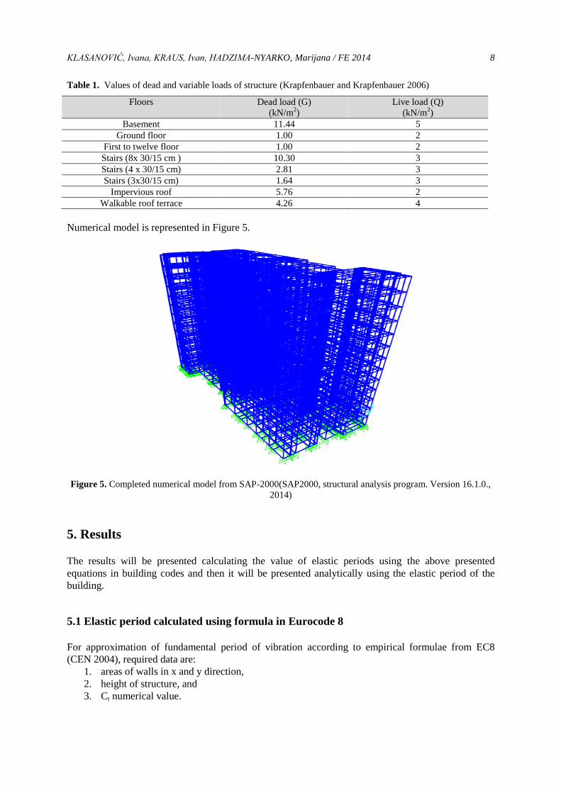
Table 1. Values of dead and variable loads of structure (Krapfenbauer and Krapfenbauer 2006)
Floors Dead load (G)
(kN/m2)
Live load (Q)
(kN/m2)
Basement 11.44 5
Ground floor 1.00 2
First to twelve floor 1.00 2
Stairs (8x 30/15 cm ) 10.30 3
Stairs (4 x 30/15 cm) 2.81 3
Stairs (3x30/15 cm) 1.64 3
Impervious roof 5.76 2
Walkable roof terrace 4.26 4
Numerical model is represented in Figure 5.
Figure 5. Completed numerical model from SAP-2000(SAP2000, structural analysis program. Version 16.1.0.,
2014)
5. Results
The results will be presented calculating the value of elastic periods using the above presented
equations in building codes and then it will be presented analytically using the elastic period of the
building.
5.1 Elastic period calculated using formula in Eurocode 8
For approximation of fundamental period of vibration according to empirical formulae from EC8
(CEN 2004), required data are:
1. areas of walls in x and y direction,
2. height of structure, and
3. Ct numerical value.
KLASANOVIĆ, Ivana, KRAUS, Ivan, HADZIMA-NYARKO, Marijana / FE 2014 9
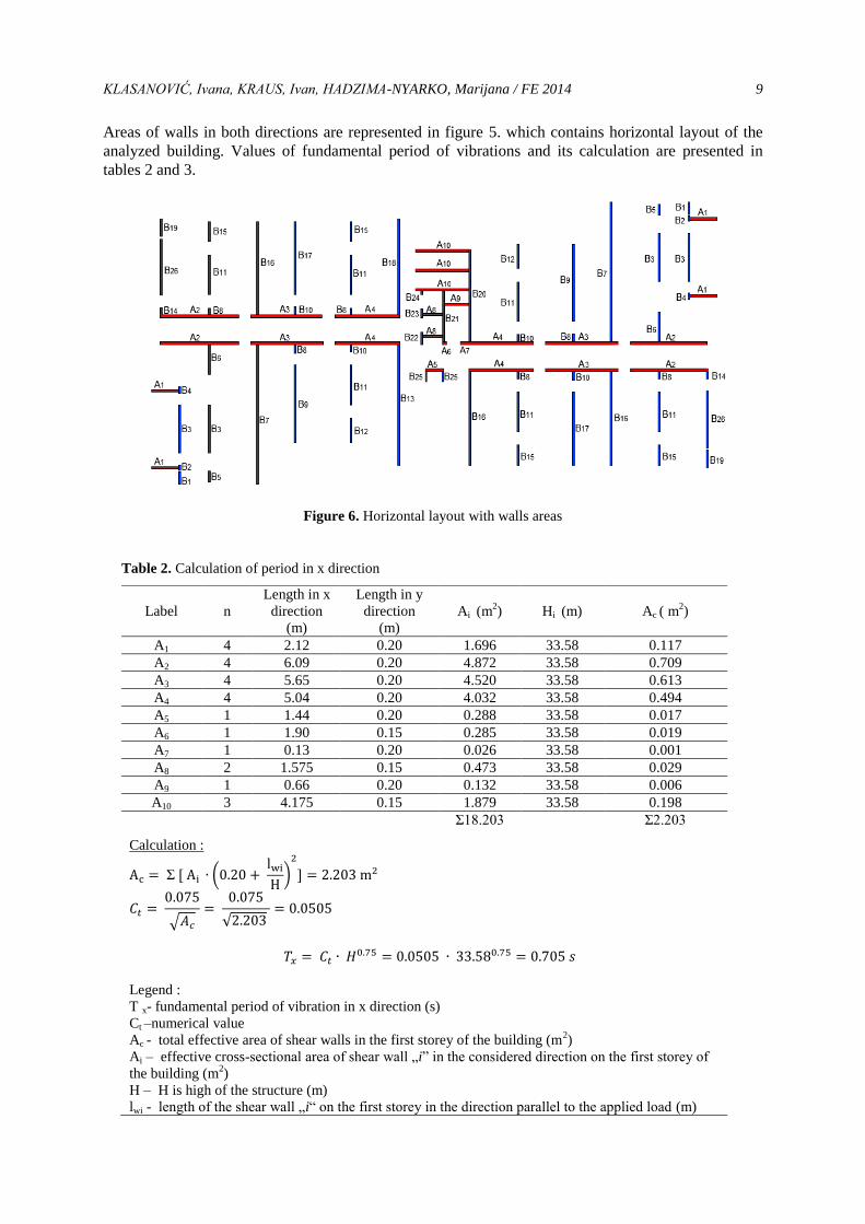
Areas of walls in both directions are represented in figure 5. which contains horizontal layout of the
analyzed building. Values of fundamental period of vibrations and its calculation are presented in
tables 2 and 3.
Figure 6. Horizontal layout with walls areas
Table 2. Calculation of period in x direction
Label
n
Length in x
direction
(m)
Length in y
direction
(m)
Ai (m2)
Hi (m)
Ac ( m2)
A1 4 2.12 0.20 1.696 33.58 0.117
A2 4 6.09 0.20 4.872 33.58 0.709
A3 4 5.65 0.20 4.520 33.58 0.613
A4 4 5.04 0.20 4.032 33.58 0.494
A5 1 1.44 0.20 0.288 33.58 0.017
A6 1 1.90 0.15 0.285 33.58 0.019
A7 1 0.13 0.20 0.026 33.58 0.001
A8 2 1.575 0.15 0.473 33.58 0.029
A9 1 0.66 0.20 0.132 33.58 0.006
A10 3 4.175 0.15 1.879 33.58 0.198
Σ18.203 Σ2.203
Σ (
)
√
√
Calculation :
Legend :
T x- fundamental period of vibration in x direction (s)
Ct –numerical value
Ac - total effective area of shear walls in the first storey of the building (m2)
Ai – effective cross-sectional area of shear wall „i” in the considered direction on the first storey of
the building (m2)
H – H is high of the structure (m)
lwi - length of the shear wall „i“ on the first storey in the direction parallel to the applied load (m)
KLASANOVIĆ, Ivana, KRAUS, Ivan, HADZIMA-NYARKO, Marijana / FE 2014 10
Table 3. Calculation of period in y direction
Label
n
Length in x
direction
(m)
Length in y
direction
(m)
Ai (ft2)
Hi (ft)
Ac(ft2)
B1 2 0.15 0.88 0.264 33.58 0.014
B2 2 0.15 0.37 0.111 33.58 0.005
B3 4 0.15 3.40 2.040 33.58 0.185
B4 2 0.15 0.44 0.132 33.58 0.006
B5 2 0.15 0.78 0.234 33.58 0.012
B6 2 0.15 2.1 0.630 33.58 0.043
B7 2 0.15 9.91 2.973 33.58 0.729
B8 2 0.15 0.53 0.159 33.58 0.007
B9 2 0.15 4.00 1.200 33.58 0.122
B10 2 0.15 1.21 0.363 33.58 0.020
B11 4 0.15 1.41 0.846 33.58 0.050
B12 2 0.15 6.63 1.989 33.58 0.314
B13 1 0.15 6.80 1.020 33.58 0.165
B14 2 0.15 5.47 1.641 33.58 0.216
B15 6 0.15 0.60 0.540 33.58 0.026
B16 4 0.15 0.50 0.300 33.58 0.014
B17 6 0.15 2.80 2.520 33.58 0.202
B18 2 0.15 1.71 0.513 33.58 0.032
B19 1 0.15 8.53 1.280 33.58 0.264
B20 1 0.15 0.87 0.131 33.58 0.007
B21 1 0.15 0.59 0.089 33.58 0.004
B22 1 0.15 0.22 0.033 33.58 0.001
B23 1 0.15 3.60 0.540 33.58 0.051
B24 2 0.12 0.70 0.168 33.58 0.008
B25 2 0.15 5.17 1,551 33.58 0.194
B26 1 0.15 6.53 0.980 33.58 0.152
Σ239.443 33.58 Σ2.844
Calculation :
Σ ( (
)
√
√
5.2 Elastic period calculated using formula in ATC3-06
Calculation of period is related with dimension D which is the dimension of the building at its base in
the direction under consideration (ft).
Fundamental period is calculated in both directions and the expressions are:
√
√ ,
√
√ .
KLASANOVIĆ, Ivana, KRAUS, Ivan, HADZIMA-NYARKO, Marijana / FE 2014 11
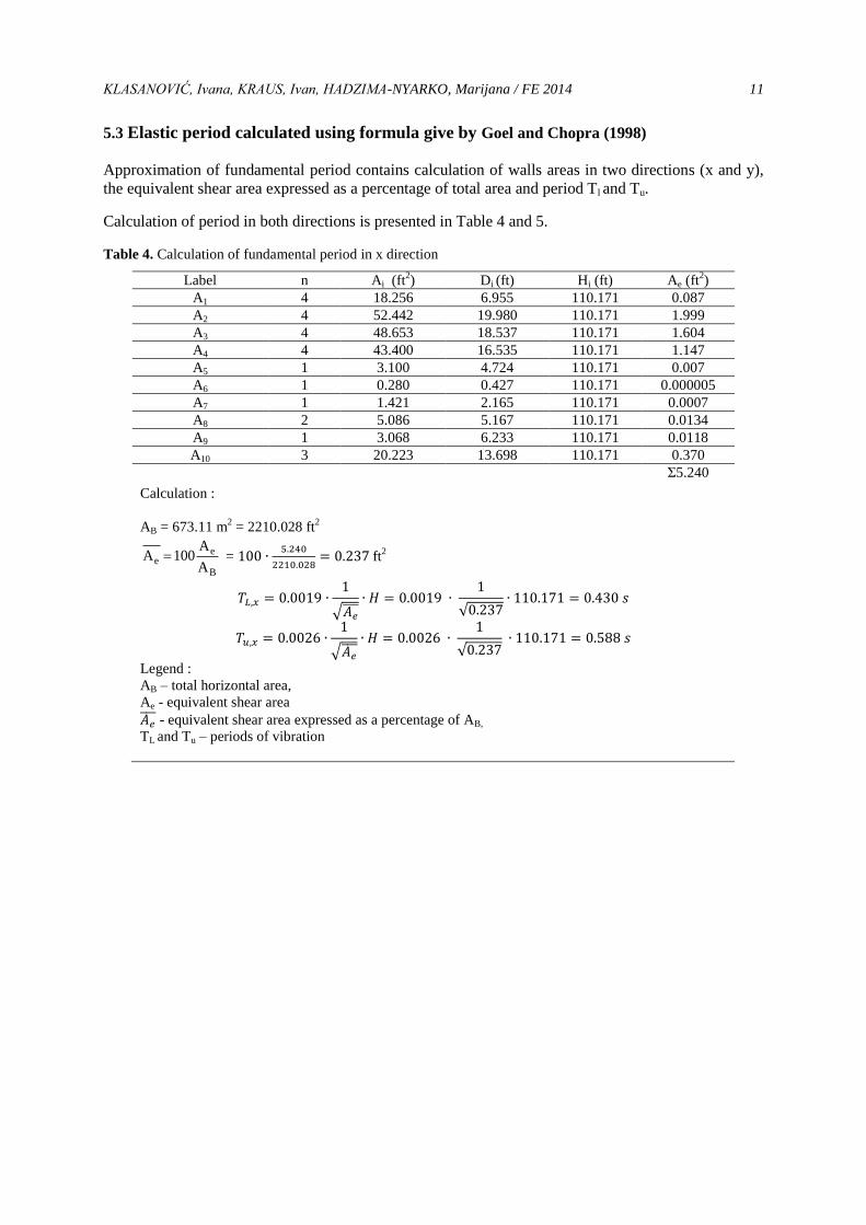
5.3 Elastic period calculated using formula give by Goel and Chopra (1998)
Approximation of fundamental period contains calculation of walls areas in two directions (x and y),
the equivalent shear area expressed as a percentage of total area and period Tl and Tu.
Calculation of period in both directions is presented in Table 4 and 5.
Table 4. Calculation of fundamental period in x direction
Label n Ai (ft2) Di (ft) Hi (ft) Ae (ft
2)
A1 4 18.256 6.955 110.171 0.087
A2 4 52.442 19.980 110.171 1.999
A3 4 48.653 18.537 110.171 1.604
A4 4 43.400 16.535 110.171 1.147
A5 1 3.100 4.724 110.171 0.007
A6 1 0.280 0.427 110.171 0.000005
A7 1 1.421 2.165 110.171 0.0007
A8 2 5.086 5.167 110.171 0.0134
A9 1 3.068 6.233 110.171 0.0118
A10 3 20.223 13.698 110.171 0.370
Σ5.240
Calculation :
AB = 673.11 m2 = 2210.028 ft
2
B
ee
A
A100A =
ft2
√
√
√
√
Legend :
AB – total horizontal area,
Ae - equivalent shear area
- equivalent shear area expressed as a percentage of AB,
TL and Tu – periods of vibration
KLASANOVIĆ, Ivana, KRAUS, Ivan, HADZIMA-NYARKO, Marijana / FE 2014 12
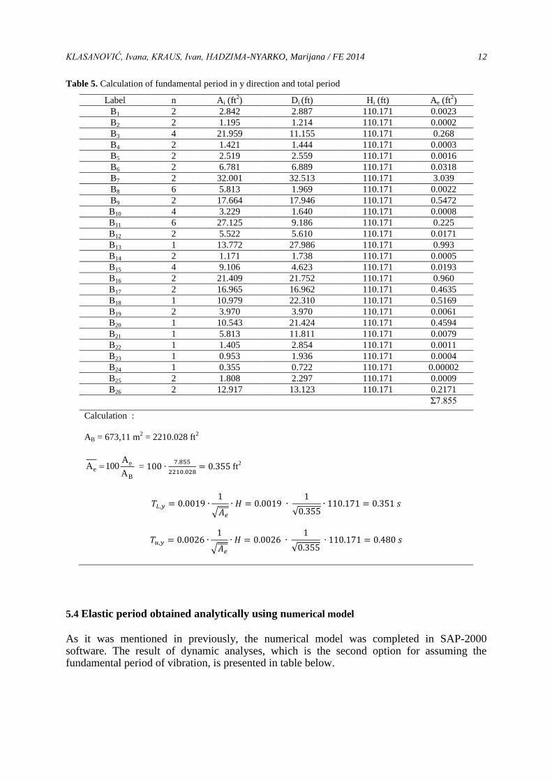
Table 5. Calculation of fundamental period in y direction and total period
Label n Ai (ft2) Di (ft) Hi (ft) Ae (ft
2)
B1 2 2.842 2.887 110.171 0.0023
B2 2 1.195 1.214 110.171 0.0002
B3 4 21.959 11.155 110.171 0.268
B4 2 1.421 1.444 110.171 0.0003
B5 2 2.519 2.559 110.171 0.0016
B6 2 6.781 6.889 110.171 0.0318
B7 2 32.001 32.513 110.171 3.039
B8 6 5.813 1.969 110.171 0.0022
B9 2 17.664 17.946 110.171 0.5472
B10 4 3.229 1.640 110.171 0.0008
B11 6 27.125 9.186 110.171 0.225
B12 2 5.522 5.610 110.171 0.0171
B13 1 13.772 27.986 110.171 0.993
B14 2 1.171 1.738 110.171 0.0005
B15 4 9.106 4.623 110.171 0.0193
B16 2 21.409 21.752 110.171 0.960
B17 2 16.965 16.962 110.171 0.4635
B18 1 10.979 22.310 110.171 0.5169
B19 2 3.970 3.970 110.171 0.0061
B20 1 10.543 21.424 110.171 0.4594
B21 1 5.813 11.811 110.171 0.0079
B22 1 1.405 2.854 110.171 0.0011
B23 1 0.953 1.936 110.171 0.0004
B24 1 0.355 0.722 110.171 0.00002
B25 2 1.808 2.297 110.171 0.0009
B26 2 12.917 13.123 110.171 0.2171
Σ7.855
Calculation :
AB = 673,11 m2 = 2210.028 ft
2
B
ee
A
A100A =
ft2
√
√
√
√
5.4 Elastic period obtained analytically using numerical model
As it was mentioned in previously, the numerical model was completed in SAP-2000 software. The result of dynamic analyses, which is the second option for assuming the fundamental period of vibration, is presented in table below.
KLASANOVIĆ, Ivana, KRAUS, Ivan, HADZIMA-NYARKO, Marijana / FE 2014 13
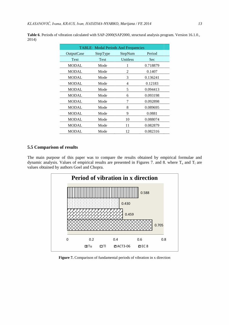
Table 6. Periods of vibration calculated with SAP-2000(SAP2000, structural analysis program. Version 16.1.0.,
2014)
TABLE: Modal Periods And Frequencies
OutputCase StepType StepNum Period
Text Text Unitless Sec
MODAL Mode 1 0.718879
MODAL Mode 2 0.1407
MODAL Mode 3 0.136241
MODAL Mode 4 0.12183
MODAL Mode 5 0.094413
MODAL Mode 6 0.093198
MODAL Mode 7 0.092898
MODAL Mode 8 0.089695
MODAL Mode 9 0.0881
MODAL Mode 10 0.088074
MODAL Mode 11 0.082879
MODAL Mode 12 0.082316
5.5 Comparison of results The main purpose of this paper was to compare the results obtained by empirical formulae and
dynamic analysis. Values of empirical results are presented in Figures 7. and 8. where Tu and Tl are
values obtained by authors Goel and Chopra.
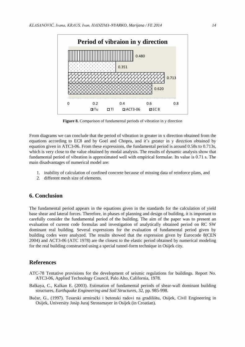
Figure 7. Comparison of fundamental periods of vibration in x direction
0.705
0.459
0.430
0.588
0 0.2 0.4 0.6 0.8
Period of vibration in x direction
Tu Tl ACT3-06 EC 8
KLASANOVIĆ, Ivana, KRAUS, Ivan, HADZIMA-NYARKO, Marijana / FE 2014 14
Figure 8. Comparison of fundamental periods of vibration in y direction
From diagrams we can conclude that the period of vibration in greater in x direction obtained from the
equations according to EC8 and by Goel and Chopra, and it’s greater in y direction obtained by
equation given in ATC3-06. From these expressions, the fundamental period is around 0.58s to 0.713s,
which is very close to the value obtained by modal analysis. The results of dynamic analysis show that
fundamental period of vibration is approximated well with empirical formulae. Its value is 0.71 s. The
main disadvantages of numerical model are:
1. inability of calculation of confined concrete because of missing data of reinforce plans, and
2. different mesh size of elements.
6. Conclusion
The fundamental period appears in the equations given in the standards for the calculation of yield
base shear and lateral forces. Therefore, in phases of planning and design of building, it is important to
carefully consider the fundamental period of the building. The aim of the paper was to present an
evaluation of current code formulas and investigation of analytically obtained period on RC SW
dominant real building. Several expressions for the evaluation of fundamental period given by
building codes were analyzed. The results showed that the expression given by Eurocode 8(CEN
2004) and ACT3-06 (ATC 1978) are the closest to the elastic period obtained by numerical modeling
for the real building constructed using a special tunnel-form technique in Osijek city.
References ATC-78 Tentative provisions for the development of seismic regulations for buildings. Report No.
ATC3-06, Applied Technology Council, Palo Alto, California, 1978.
Balkaya, C., Kalkan E. (2003). Estimation of fundamental periods of shear-wall dominant building structures, Earthquake Engineering and Soil Structures, 32, pp. 985-998.
Bučar, G., (1997). Tesarski armirački i betonski radovi na gradilištu, Osijek, Civil Engineering in Osijek, University Josip Juraj Strossmayer in Osijek (in Croatian).
0.620
0.713
0.351
0.480
0 0.2 0.4 0.6 0.8
Period of vibraion in y direction
Tu Tl ACT3-06 EC 8
KLASANOVIĆ, Ivana, KRAUS, Ivan, HADZIMA-NYARKO, Marijana / FE 2014 15
CEN (Comité Européen de Normalisation), 2004. Eurocode 8: Design of structures for earthquake resistance Part 1: General rules, seismic actions and rules for buildings, EN 1998-1. Brussels, Belgium
Computers and Structures Inc. (CSI), 2014. SAP2000, structural analysis program. Version 16.1.0. Berkeley, California, USA
Draganić, H., Hadzima-Nyarko, M., Morić, D. (2010). Compresion of RC frames periods with the empiric expressions given in EUROCODE 8, Technical Gazette 17, 1, pp. 93-100.
Eshghi S., Tavafoghi A. (2008). Seismic Behaviour of Tunnel Form Concrete Building Structures, In: Proceedings of The 14th World Conference on Earthquake Engineering, Beijing, China, October 12-17.
Eshghi S., Tavafoghi A. (2012). Seismic Behaviour of Tunnel Form Building Structures: An Experimental Study; In: Proceedings of the 15th World Conference on Earthquake Engineering, Lisbon, Portugal, 24-28 September 2012.
Goel, R.K., Chopra, A.K. (1998). Period formulas for concrete shear wall buildings, Journal of Structtural Engineering, 124, 4, pp. 426–433.
Hadzima-Nyarko, M., Morić, D., Nyarko, E.K., Draganić, H. (2014). Direction based elastic period expressions for reinforced concrete shear wall dominant structures using genetic algorithms; submitted for The Second European Conference on Earthquake Engineering and Seismology (2ECEES), Istanbul, Turkey, 24-29 August 2014.
Krapfenbauer R., Krapenbauer T., 2006. Građevinske tablice, Beč, Sajema d.o.o. (in Croatian)
Tomičić I. (1996). Betonske konstrukcije. knjiga 1., Zagreb: Društvo hrvatskih građevinskih konstruktora ( in Croatian ).
Tomostv, 2008.Sjenjak1.(electronic print) Available at:
< http://www.skyscrapercity.com/showthread.php?p=53750153 > (Accessed 12 May 2014)


![Accumulation of damage in reinforced concrete elements under … · 2020. 11. 24. · reinforced concrete buildings and structures in a nonlinear dynamic setting. References [1] US](https://img.pdfslide.net/doc/110x75/61241722d5a8997d3e72d646/accumulation-of-damage-in-reinforced-concrete-elements-under-2020-11-24-reinforced.jpg)