Embed Size (px)
Citation preview
100
1.7 Instrument Installation
I. H. GIBSON
(2003)
COST
• On the order of 40 to 50% of the capital cost of theequipment—extremely variable.
• A full set of PIP Process Control Practices documentscost U.S. $6500 in 2002.
For process measurements to achieve the targets of safety, accu-racy, reliability, and economy, more than measuring equipmentis involved. The entire system—from the process fluid charac-teristics, the ambient conditions, legal and regulatory require-ments, and operations/maintenance requirements—must becoordinated to ensure that the equipment can be installed, cal-ibrated, operated, recalibrated, maintained, and, if necessary,rebuilt or replaced while meeting the above primary criteria.
This section attempts to provide guidance to persons whoare unfamiliar with current industrial practice; it does notattempt to cover all industries and all measurements. Specif-ically, it cannot cover the multitude of legal and regulatoryrequirements mandated by bodies such as the OccupationalSafety and Health Administration (OSHA).
INSTALLATION DOCUMENTATION
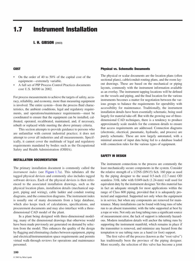
The primary installation document is commonly called the
instrument index
(see Figure 1.7a). This tabulates all thetagged physical devices and commonly also includes taggedsoftware devices. Each of the physical devices is then refer-enced to the associated installation drawings, such as thephysical location plans, installation details (mechanical sup-port, piping and wiring), cable ladder and conduit routingdiagrams, and the connection diagrams. The instrument indexis usually one of many documents from a large database,which also keeps track of calculations, specifications, andprocurement documents and may also interface with a three-dimensional CAD model of the plant.
In a plant being designed with three-dimensional model-ing, many of the dimensional drawings that otherwise wouldhave been made previously are generated on demand by selec-tion from the model. This enhances the quality of the designby flagging and eliminating clashes between equipment, pipingand electrical/instrumentation space requirements and permitsvirtual walk-through reviews for operations and maintenancepersonnel.
Physical vs. Schematic Documents
The physical or scalar documents are the location plans (oftensectional plans), cable/conduit routing plans, and the room lay-out drawings. These are based on the mechanical or pipinglayouts, commonly with the instrument information availableas an overlay. The instrument tapping locations will be definedon the vessels and piping, and the final location for the variousinstruments becomes a matter for negotiation between the var-ious groups to balance the requirements for operability withaccessibility for maintenance. Traditionally, the instrumentinstallation details have been essentially schematic, being usedlargely for material take-off. But with the growing use of three-dimensional CAD techniques, there is a tendency to produceapproximately scale models for the common details to ensurethat access requirements are addressed. Connection diagrams(electronic, electrical, pneumatic, hydraulic, and process) arepurely schematic. These are now largely automated, with aminimal amount of input data being fed to a database loadedwith connection rules for the various types of equipment.
SAFETY IN DESIGN
The instrument connections to the process are commonly theleast mechanically secure components in the system. Considerthe relative strength of a 1/2NS (DN15) Sch. 160 pipe as usedby the piping designer to the usual 0.5-inch (12.7-mm) ODseamless 316L tube with 0.049-inch (1.24-mm) wall used forequivalent duty by the instrument designer. Yet this material hasin fact an adequate strength for most applications within therange of Class 600 piping, provided that it is adequately pro-tected and supported. Supported not only when the equipmentis in service, but when any components are removed for main-tenance. Many installations can be found with long runs of tuberun to an absent transmitter, with the tube supported at best bya rope or wire. Not only are long tubing runs a significant sourceof measurement error, the lack of support is inherently hazard-ous. Modern installation details will anchor the tubing runs bysupporting the instrument manifold, which remains in place ifthe transmitter is removed, and minimize any hazard from thetemptation to use tubing runs as a hand (or foot) support.
The first valve off the process (known as the “root valve”)has traditionally been the province of the piping designer.More recently, the selection of this valve has become a joint
© 2003 by Béla Lipták
1.7Instrum
ent Installation
101
FIG. 1.7a
Typical instrument index report (extracted from Intools database).
No. By Date Chk App
1
Dwg. Name:
Sheet of 3
Domain:FDMELB
DEFAULT STYLE Report
Test 1 Test 2 Test 3 Test 4Filter: None
Sort: None
Plant name:Area name:Unit name: Crude unit 1
Crude AreaNew Refinery
Horizontal Section 1 of 1
Last Revision:Revision Client
Tag Number Instrument Type I/O Type Status Service Location Equipment Manufacturer Model Price
101-FE -100 D/P TYPE FLOW ELEMENT N Feed from V-8 Field FISHER-PORTER $110
101-FT -100 D/P TYPE FLOW TRANSMITTER AI N Feed from V-8 Field ROSEMOUNT 1151DP4E22S2B1M2 $1095
101-FY -100 I/P TRANSDUCER AO N Feed from V-8 Field FISHER 461 $580
101-FV -100 CONTROL VALVE N Feed from V-8 Field FISHER ES $3250
101-PI -100 PRESSURE GAUGE N Heat exchanger inlet Field ASHCROFT MGS-136 $65
101-PI -102 PRESSURE GAUGE N Heat exchanger outlet Field ASHCROFT MGS-136 $65
101-HY -101 I/P TRANSDUCER AO N C-101 Bypass Field C-101 FISHER 461 $580
101-HV -101 CONTROL VALVE N C-101 Bypass Field FISHER ET $2100
101-FE -102 D/P TYPE FLOW ELEMENT N Feed from C-1 Field $120
101-FT -102 D/P TYPE FLOW TRANSMITTER AI N Feed from C-1 Field ROSEMOUNT 1151DP4E22S2B1M2 $1095
101-PI -101 PRESSURE GAUGE N F-102 Stripper inlet Field ASHCROFT MGS-136 $65
101-TW -203 THERMOWELL N F-102 Overhead Field
101-TI -203 BI-METAL THERMOMETER N F-102 Overhead Field ASHCROFT EVERY-ANGLE-13/02 $45
101-PSH -208 HIGH-PRESSURE SWITCH N F-102 Overhead Field ASCO 8351B23 $720
101-PT -201 PRESSURE TRANSMITTER AI N F-102 TOP Field F-102 ROSEMOUNT 3051S1256 $1095
101-LT -201 DISPLACER TYPE LEVEL AI N F-102 Middle section Field F-102 MASONEILAN 9600 $1095
101-LY -201 I/P TRANSDUCER AO N F-102 Middle section Field FISHER 461 $580
101-LV -201 CONTROL VALVE N F-102 Middle section Field FISHER ED $1340
101-TW -202 THERMOWELL N F-102 Top Field F-102 $45
101-TE -202 THERMOCOUPLE N F-102 Top Field F-102 ASHFORD TE-11-34/13 $22
101-TT -202 TEMPERATURE TRANSMITTER AI N F-102 Top Field F-102 ROSEMOUNT 3051S1256 $650
101-TY -202 I/P TRANSDUCER AO N F-102 Top Field FISHER 461 $580
101-TV -202 CONTROL VALVE N F-102 Top Field FISHER V500 $2300
101-TW -201 THERMOWELL N F-102 Top Field F-102 $51
101-TI -201 BI-METAL THERMOMETER N F-102 Top Field F-102 ASHCROFT EVERY-ANGLE-13/02 $45
101-FT -201 D/P TYPE FLOW TRANSMITTER AI N Stripping Steam to F-102 Field ROSEMOUNT 1151DP4E22S2B1M2 $1095
DI
© 2003 by Béla Lipták
102
General Considerations
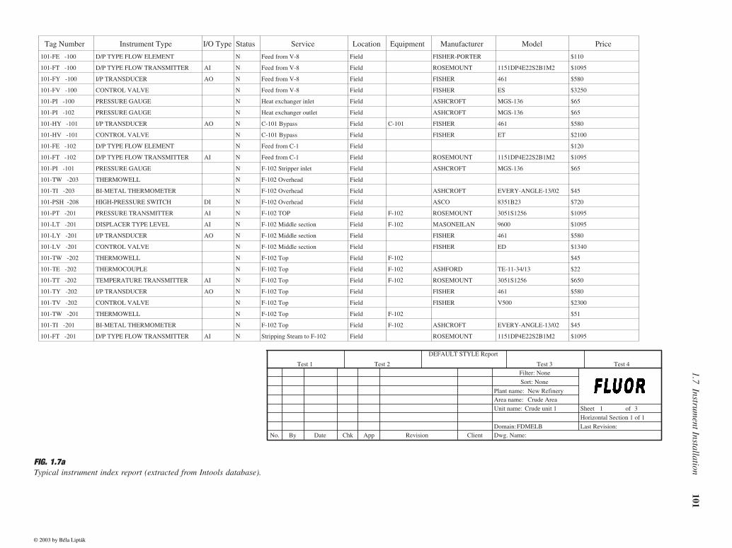
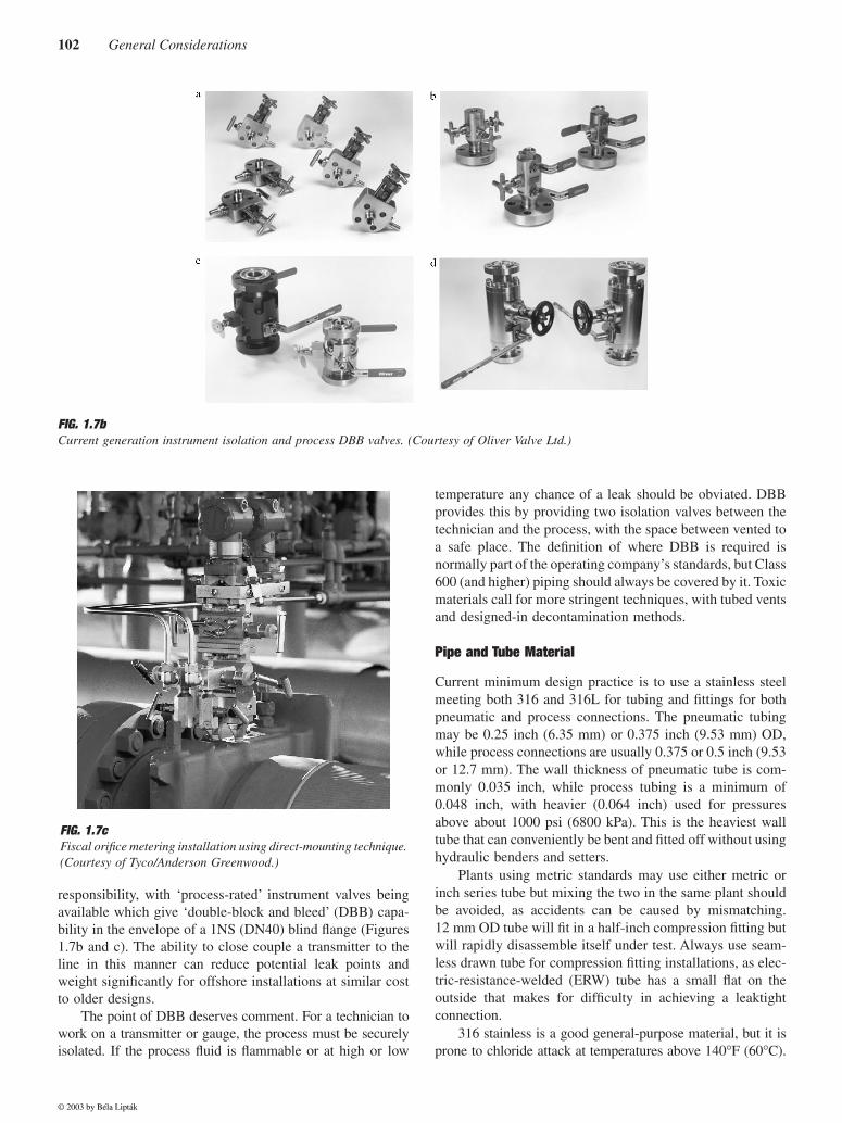
responsibility, with ‘process-rated’ instrument valves beingavailable which give ‘double-block and bleed’ (DBB) capa-bility in the envelope of a 1NS (DN40) blind flange (Figures1.7b and c). The ability to close couple a transmitter to theline in this manner can reduce potential leak points andweight significantly for offshore installations at similar costto older designs.
The point of DBB deserves comment. For a technician towork on a transmitter or gauge, the process must be securelyisolated. If the process fluid is flammable or at high or low
temperature any chance of a leak should be obviated. DBBprovides this by providing two isolation valves between thetechnician and the process, with the space between vented toa safe place. The definition of where DBB is required isnormally part of the operating company’s standards, but Class600 (and higher) piping should always be covered by it. Toxicmaterials call for more stringent techniques, with tubed ventsand designed-in decontamination methods.
Pipe and Tube Material
Current minimum design practice is to use a stainless steelmeeting both 316 and 316L for tubing and fittings for bothpneumatic and process connections. The pneumatic tubingmay be 0.25 inch (6.35 mm) or 0.375 inch (9.53 mm) OD,while process connections are usually 0.375 or 0.5 inch (9.53or 12.7 mm). The wall thickness of pneumatic tube is com-monly 0.035 inch, while process tubing is a minimum of0.048 inch, with heavier (0.064 inch) used for pressuresabove about 1000 psi (6800 kPa). This is the heaviest walltube that can conveniently be bent and fitted off without usinghydraulic benders and setters.
Plants using metric standards may use either metric orinch series tube but mixing the two in the same plant shouldbe avoided, as accidents can be caused by mismatching.12 mm OD tube will fit in a half-inch compression fitting butwill rapidly disassemble itself under test. Always use seam-less drawn tube for compression fitting installations, as elec-tric-resistance-welded (ERW) tube has a small flat on theoutside that makes for difficulty in achieving a leaktightconnection.
316 stainless is a good general-purpose material, but it isprone to chloride attack at temperatures above 140
°
F (60
°
C).
FIG. 1.7b
Current generation instrument isolation and process DBB valves. (Courtesy of Oliver Valve Ltd.)
FIG. 1.7c
Fiscal orifice metering installation using direct-mounting technique.(Courtesy of Tyco/Anderson Greenwood.)
© 2003 by Béla Lipták
1.7 Instrument Installation
103
This can be significant both internally and externally—tropicalmarine installations can easily achieve such temperature insunlight. Monel
(cupronickel) and duplex stainless are bothwidely used in such locations; duplex offers higher tensilestrength and pressure rating. Ensure that the tube wall thicknesschosen meets the most stringent pressure and temperature com-bination likely to be found.
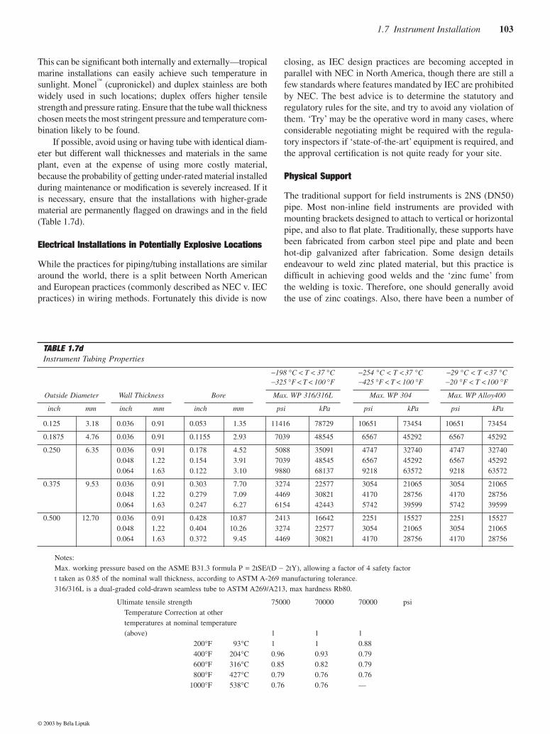
If possible, avoid using or having tube with identical diam-eter but different wall thicknesses and materials in the sameplant, even at the expense of using more costly material,because the probability of getting under-rated material installedduring maintenance or modification is severely increased. If itis necessary, ensure that the installations with higher-gradematerial are permanently flagged on drawings and in the field(Table 1.7d).
Electrical Installations in Potentially Explosive Locations
While the practices for piping/tubing installations are similararound the world, there is a split between North Americanand European practices (commonly described as NEC v. IECpractices) in wiring methods. Fortunately this divide is now
closing, as IEC design practices are becoming accepted inparallel with NEC in North America, though there are still afew standards where features mandated by IEC are prohibitedby NEC. The best advice is to determine the statutory andregulatory rules for the site, and try to avoid any violation ofthem. ‘Try’ may be the operative word in many cases, whereconsiderable negotiating might be required with the regula-tory inspectors if ‘state-of-the-art’ equipment is required, andthe approval certification is not quite ready for your site.
Physical Support
The traditional support for field instruments is 2NS (DN50)pipe. Most non-inline field instruments are provided withmounting brackets designed to attach to vertical or horizontalpipe, and also to flat plate. Traditionally, these supports havebeen fabricated from carbon steel pipe and plate and beenhot-dip galvanized after fabrication. Some design detailsendeavour to weld zinc plated material, but this practice isdifficult in achieving good welds and the ‘zinc fume’ fromthe welding is toxic. Therefore, one should generally avoidthe use of zinc coatings. Also, there have been a number of
TABLE 1.7d
Instrument Tubing Properties
−
198
°
C
<
T
<
37
°
C
−
325
°
F
<
T
<
100
°
F
−
254
°
C
<
T
<
37
°
C
−
425
°
F
<
T
<
100
°
F
−
29
°
C
<
T
<
37
°
C
−
20
°
F
<
T
<
100
°
F
Outside Diameter Wall Thickness Bore Max. WP 316/316L Max. WP 304 Max. WP Alloy400
inch mm inch mm inch mm psi kPa psi kPa psi kPa
0.125 3.18 0.036 0.91 0.053 1.35 11416 78729 10651 73454 10651 73454
0.1875 4.76 0.036 0.91 0.1155 2.93 7039 48545 6567 45292 6567 45292
0.250 6.35 0.0360.0480.064
0.911.221.63
0.1780.1540.122
4.52 3.91 3.10
5088 7039 9880
350914854568137
4747 6567 9218
327404529263572
4747 6567 9218
327404529263572
0.375 9.53 0.0360.0480.064
0.911.221.63
0.3030.2790.247
7.70 7.09 6.27
3274 4469 6154
225773082142443
3054 4170 5742
210652875639599
3054 4170 5742
210652875639599
0.500 12.70 0.0360.0480.064
0.911.221.63
0.4280.4040.372
10.8710.26 9.45
2413 3274 4469
166422257730821
2251 3054 4170
155272106528756
2251 3054 4170
155272106528756
Notes:Max. working pressure based on the ASME B31.3 formula P
=
2tSE/(D
−
2tY), allowing a factor of 4 safety factort taken as 0.85 of the nominal wall thickness, according to ASTM A-269 manufacturing tolerance.316/316L is a dual-graded cold-drawn seamless tube to ASTM A269/A213, max hardness Rb80.
Ultimate tensile strengthTemperature Correction at othertemperatures at nominal temperature(above)
75000
1
70000
1
70000
1
psi
200
°
F 400
°
F 600
°
F 800
°
F1000
°
F
93
°
C204
°
C316
°
C427
°
C538
°
C
10.960.850.790.76
10.930.820.760.76
0.880.790.790.76—
© 2003 by Béla Lipták
104
General Considerations
significant failures of stainless and high alloy piping whenminor fires melted the zinc from galvanized walkways, etc.If molten zinc comes in contact with an austenitic alloy, itpenetrates its grain structure within seconds and the strengthof the alloy vanishes. To protect from this effect and to avoidcorrosion, a number of sites are now using stainless steel“strut” supports.
PROCESS INDUSTRIES PRACTICES
A consortium of the major petroleum, chemical, and relatedmanufacturers, together with major engineer-constructors havejoined to form the Process Industry Practices (PIP) division ofthe Construction Industry Institute, an organization associ-ated with The University of Texas at Austin. The PIP officesare located to 3925 West Braker Lane (R4500), Austin, TX78759.
PIP (website
http://www.pip.org
) has generated a wide-ranging series of standard practices in a variety of engineer-ing fields. Among the 20 Practices for Process Control aresome 9 sets covering instrument installation. These are avail-able to members of the consortium and subscribers for theirdirect use, and can be purchased by other organizationsFigures 1.7e, f, and g).
In an effort to minimize the cost of process industry facil-ities, these Practices have been prepared from the technicalrequirements in the existing standards of major industrialusers, contractors, or standards organisations. By harmonis-ing these technical requirements into a single set of Practices,administrative, application, and engineering costs to both thepurchaser and the manufacturer should be reduced. Whilethese Practices are expected to incorporate the majority ofrequirements of most users, individual applications mayinvolve requirements that will be appended to and take pre-cedence over individual Practices. Determinations concern-ing fitness for purpose and particular matters or applicationof the Practice to particular project or engineering situationsshould not be made solely on information contained in thesematerials.
The tabulation of PIP installation documents (Table 1.7h)is not exhaustive, and they are frequently edited and extended.
Bibliography
Process Industry Practices (see Table 1.7h) issued by Process Industry Prac-tices, 3925 West Braker Lane (R4500), Austin, TX 78759, USA.
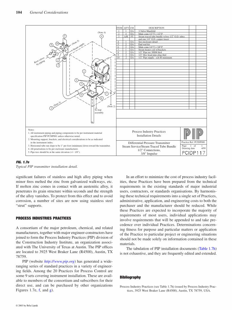
FIG. 1.7e
Typical PIP transmitter installation detail.
Notes:1. All instrument piping and piping components to be per instrument material specification PIP PCSIP001 unless otherwise noted.2. Mounting support, brackets, and electrical considerations to be as indicated in the instrument index.3. Horizontal tube run slope to be 1" per foot (minimum) down toward the transmitter.4. All penetrations to be per enclosure manufacturer.5. Pipe tees should be at the same elevation (+/− 1/8").
ITEM QTY UM DESCRIPTION 1 1 EA 3-Valve Manifold 2 4 EA Male conn 1/2"T × 1/2"P 3 A/R FT Steam traced tube bundle w/two 1/2" O.D. tubes
and one 1/4" O.D. copper tracer 4 1 EA See enclosure detail 5 2 EA End seal kit 6 2 EA Male conn 1/4"T × 3/8"P 7 1 EA Steam heater coil w/brackets 8 2 EA 1/2" Pipe tee 3000# thrd 9 2 EA 1/2" Hex head pipe plug thrd 10 2 EA 1/2" Pipe nipple - sch 80 minimum
Process Industry PracticesInstallation Details
Differential Pressure TransmitterSteam Service/Steam Traced Tube Bundle
1/2" Connections,3/8" Impulse
Practice Ref. PCIDP000
Page 1 of 1Drawing date 4/99
9
108
2
5
1
2
5
H
L
6
6
7
(Note 2)
4
(Note 4)
To trapassembly
(Note 3)
Root valves
by piping
(Note 5)
Steam supply
3
© 2003 by Béla Lipták
1.7 Instrument Installation
105
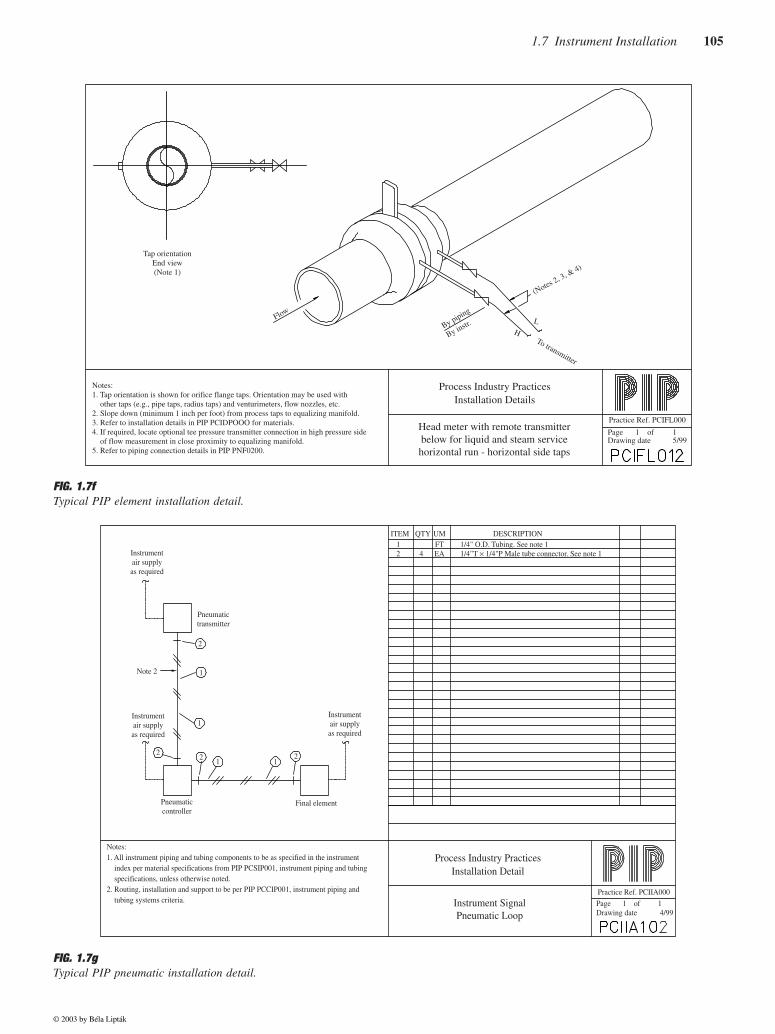
FIG. 1.7f
Typical PIP element installation detail.
FIG. 1.7g
Typical PIP pneumatic installation detail.
Practice Ref. PCIFL000
Page 1 of 1Drawing date 5/99
Notes:1. Tap orientation is shown for orifice flange taps. Orientation may be used with other taps (e.g., pipe taps, radius taps) and venturimeters, flow nozzles, etc.2. Slope down (minimum 1 inch per foot) from process taps to equalizing manifold.3. Refer to installation details in PIP PCIDPOOO for materials.4. If required, locate optional tee pressure transmitter connection in high pressure side of flow measurement in close proximity to equalizing manifold.5. Refer to piping connection details in PIP PNF0200.
Process Industry PracticesInstallation Details
Head meter with remote transmitterbelow for liquid and steam servicehorizontal run - horizontal side taps
Tap orientationEnd view(Note 1)
Flow
By piping
By instr.H
L
To transmitter
(Notes 2, 3, & 4)
Notes:1. All instrument piping and tubing components to be as specified in the instrument index per material specifications from PIP PCSIP001, instrument piping and tubing specifications, unless otherwise noted.2. Routing, installation and support to be per PIP PCCIP001, instrument piping and tubing systems criteria.
ITEM QTY UM DESCRIPTION 1 FT 1/4" O.D. Tubing. See note 1 2 4 EA 1/4"T × 1/4"P Male tube connector. See note 1
Process Industry PracticesInstallation Detail
Instrument SignalPneumatic Loop
Practice Ref. PCIIA000
Page 1 of 1Drawing date 4/99
Pneumaticcontroller
Final element
Instrumentair supplyas required
Instrumentair supplyas required
Instrumentair supplyas required
Note 2
Pneumatictransmitter
22 2
2
1
1
1 1
© 2003 by Béla Lipták
106
General Considerations
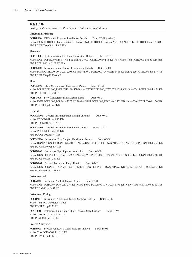
TABLE 1.7h
Listing of Process Industry Practices for Instrument Installation
Differential Pressure
PCIDP000
Differential Pressure Installation Details Date: 07-01 (revised)Native DGN PCIDP000_dgn.exe 5265 KB Native DWG PCIDP000_dwg.exe 9651 KB Native Text PCIDP000.doc 89 KB PDF PCIDP000.pdf 4415 KB File
Electrical
PCFEL000
Instrumentation Electrical Fabrication Details Date: 12-99Native DGN PCFEL000.dgn 97 KB File Native DWG PCFEL000.dwg 96 KB File Native Text PCFEL000.doc 50 KB File PDF PCFEL000.pdf 122 KB File
PCIEL000
Instrumentation Electrical Installation Details Date: 02-00Native DGN PCIEL000_DNG.ZIP 2293 KB Native DWG PCIEL000_DWG.ZIP 3485 KB Native Text PCIEL000.doc 119 KB PDF PCIEL000.pdf 3040 KB
Flow
PCFFL000
Flow Measurement Fabrication Details Date: 01-01Native DGN PCFFL000_DGN.EXE 1294 KB Native DWG PCFFL000_DWG.ZIP 1334 KB Native Text PCFFL000.doc 74 KBPDF PCFFL000.pdf 238 KB
PCIFL000
Flow Measurement Installation Details Date: 04-01Native DGN PCIFL000_DGN.exe 2573 KB Native DWG PCIFL000_DWG.exe 3532 KB Native Text PCIFL000.doc 76 KB PDF PCIFL000.pdf 594 KB
General
PCCGN001
General Instrumentation Design Checklist Date: 07-01Native PCCGN001.doc 893 KB PDF PCCGN001.pdf 157 KB
PCCGN002
General Instrument Installation Criteria Date: 10-01Native PCCGN002.doc 104 KB PDF PCCGN002.pdf 44 KB
PCFGN000
Instrument Pipe Support Fabrication Details Date: 06-00Native DGN PCFGN000_DGN.EXE 204 KB Native DWG PCFGN000_DWG.ZIP 248 KB Native Text PCFGN000.doc 93 KBPDF PCFGN000.pdf 314 KB
PCIGN000
Instrument Pipe Support Installation Date: 06-00Native DGN PCIGN000_DGN.ZIP 329 KB Native DWG PCIGN000_DWG.ZIP 475 KB Native Text PCIGN000.doc 68 KB PDF PCIGN000.pdf 341 KB
PCIGN001
General Instrument Purge Details Date: 09-01Native DGN PCIGN001_DGN.ZIP 860 KB Native DWG PCIGN001_DWG.ZIP 697 KB Native Text PCIGN001.doc 68 KBPDF PCIGN001.pdf 234 KB
Instrument Air
PCIIA000
Instrument Air Installation Details Date: 07-01Native DGN PCIIA000_DGN.ZIP 274 KB Native DWG PCIIA000_DWG.ZIP 1175 KB Native Text PCIIA000.doc 62 KBPDF PCIIA000.pdf 482 KB
Instrument Piping
PCCIP001
Instrument Piping and Tubing Systems Criteria Date: 07-98Native Text PCCIP001.doc 88 KB PDF PCCIP001.pdf 30 KB
PCSIP001
Instrument Piping and Tubing Systems Specifications Date: 07-98Native Text PCSIP001.doc 121 KB PDF PCSIP001.pdf 103 KB
Process Analyzers
PCIPA001
Process Analyzer System Field Installation Date: 10-01Native Text PCIPA001.doc 110 KB PDF PCIPA001.pdf 39 KB
© 2003 by Béla Lipták

1.7 Instrument Installation
107
TABLE 1.7h Continued
Listing of Process Industry Practices for Instrument Installation
Pressure
PCIPR000
Pressure Installation Details Date: 04-99Native DGN PCIPR000_dgn.exe 3912 KB Native DWG PCIPR000_dwg.exe 3137 KB Native Text PCIPR000.doc 154 KB PDF PCIPR000.pdf 8314 KB
Temperature
PCFTE000
Temperature Measurement Fabrication Details Date: 04-00Native DGN PCFTE000_DGN.ZIP 242 KB Native DWG PCFTE000_DWG.ZIP 393 KB Native Text PCFTE000.doc 73 KB PDF PCFTE000.pdf 632 KB
© 2003 by Béla Lipták


![Concoll~i(] Theological Montblyctsfw.net/media/pdfs/CTMBookReview27-8.pdfa concordance for the Greek New Testament which tabulates alphabetically all the 5,524 individual words of](https://img.pdfslide.net/doc/110x75/5e7a194003bad7619f11ec97/concolli-theological-a-concordance-for-the-greek-new-testament-which-tabulates.jpg)