Embed Size (px)
Citation preview
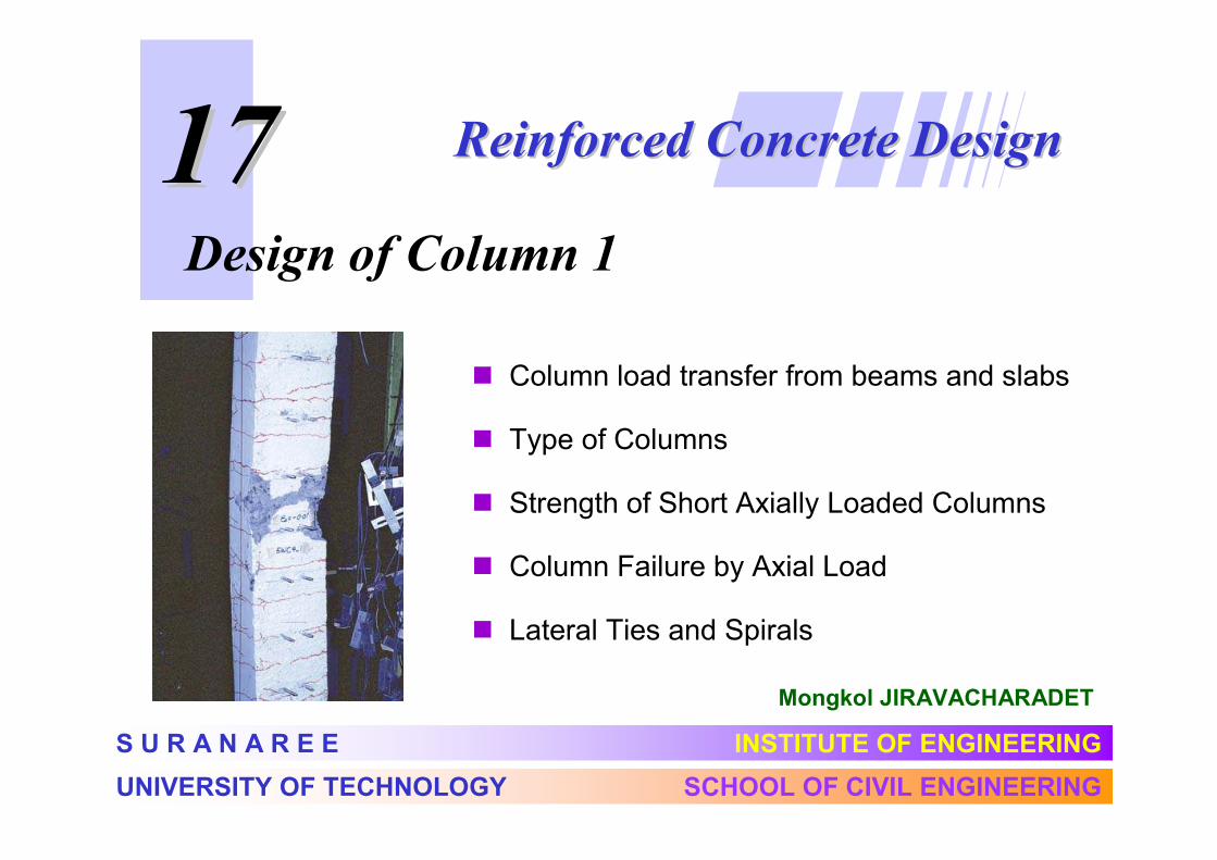
1717
Mongkol JIRAVACHARADET
Reinforced Concrete DesignReinforced Concrete Design
S U R A N A R E E INSTITUTE OF ENGINEERING
UNIVERSITY OF TECHNOLOGY SCHOOL OF CIVIL ENGINEERING
Design of Column 1
� Column load transfer from beams and slabs
� Type of Columns
� Strength of Short Axially Loaded Columns
� Column Failure by Axial Load
� Lateral Ties and Spirals
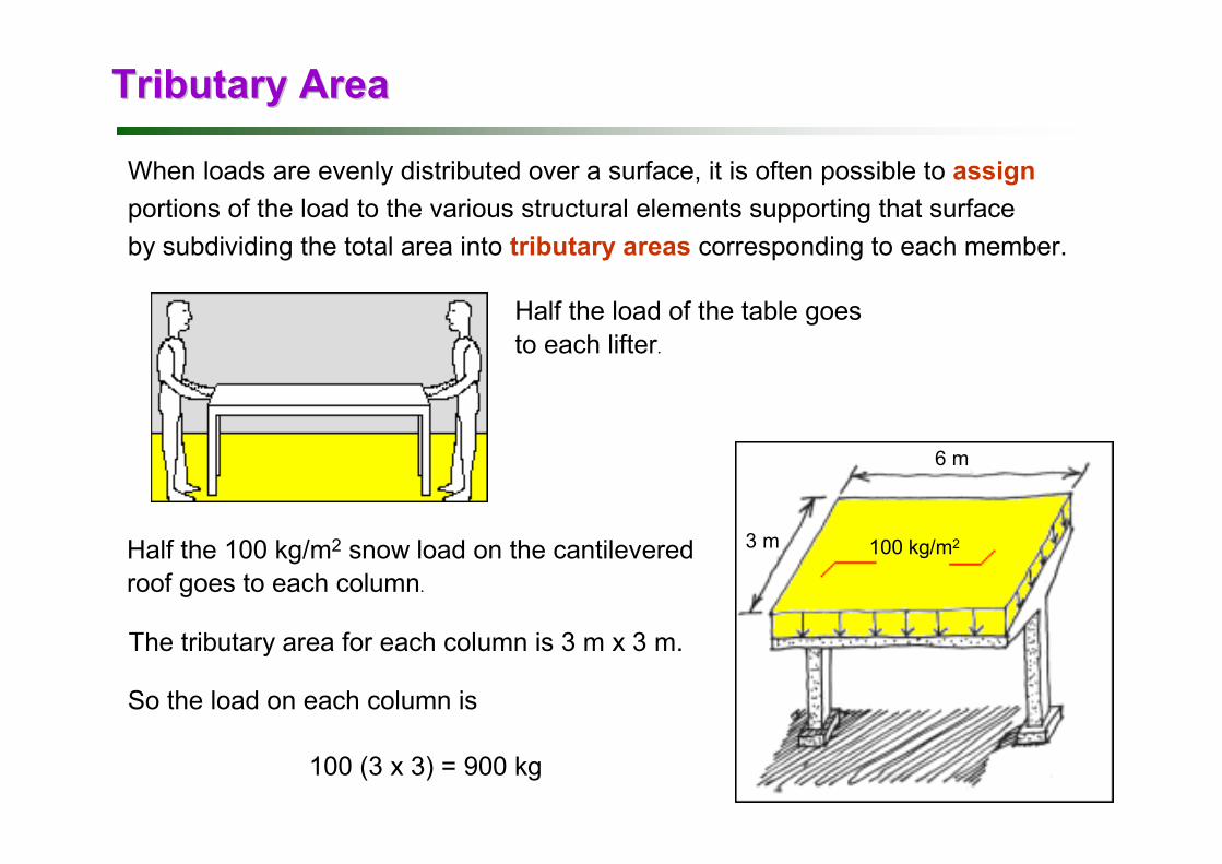
Tributary AreaTributary Area
When loads are evenly distributed over a surface, it is often possible to assign
portions of the load to the various structural elements supporting that surface
by subdividing the total area into tributary areas corresponding to each member.
Half the load of the table goes
to each lifter.
100 kg/m23 m
6 m
Half the 100 kg/m2 snow load on the cantilevered
roof goes to each column.
The tributary area for each column is 3 m x 3 m.
So the load on each column is
100 (3 x 3) = 900 kg
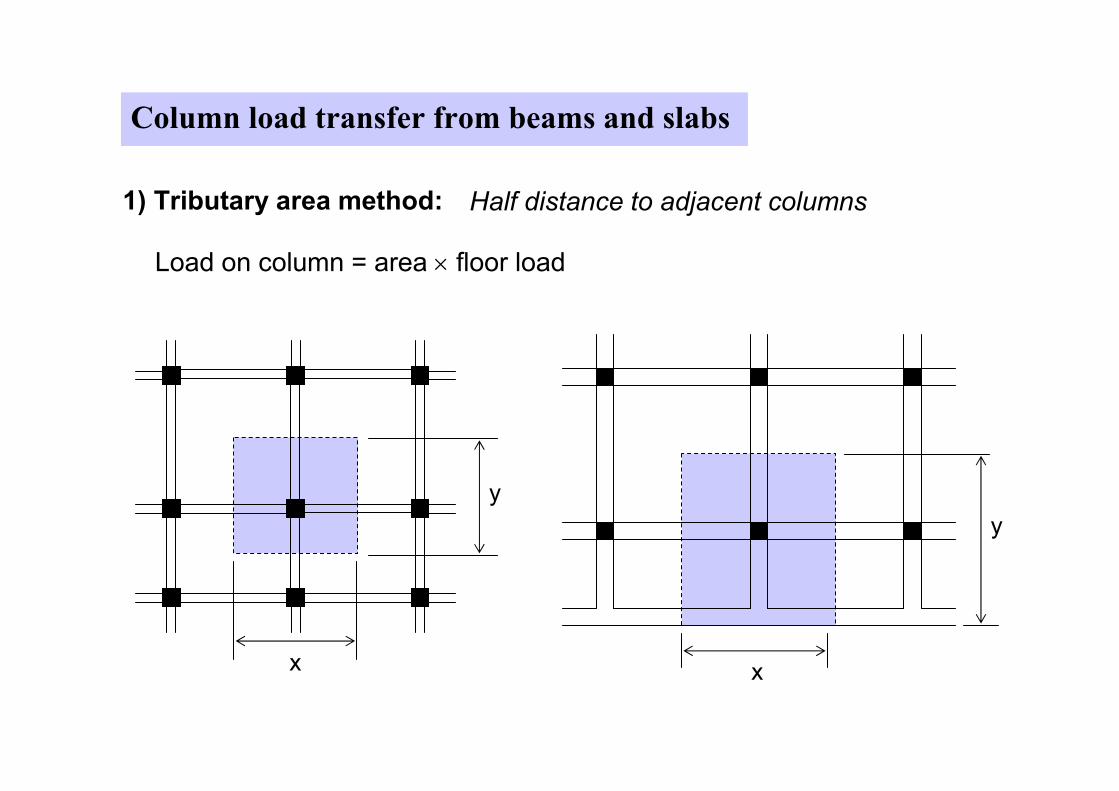
Column load transfer from beams and slabs
1) Tributary area method: Half distance to adjacent columns
y
x
Load on column = area × floor load
y
x
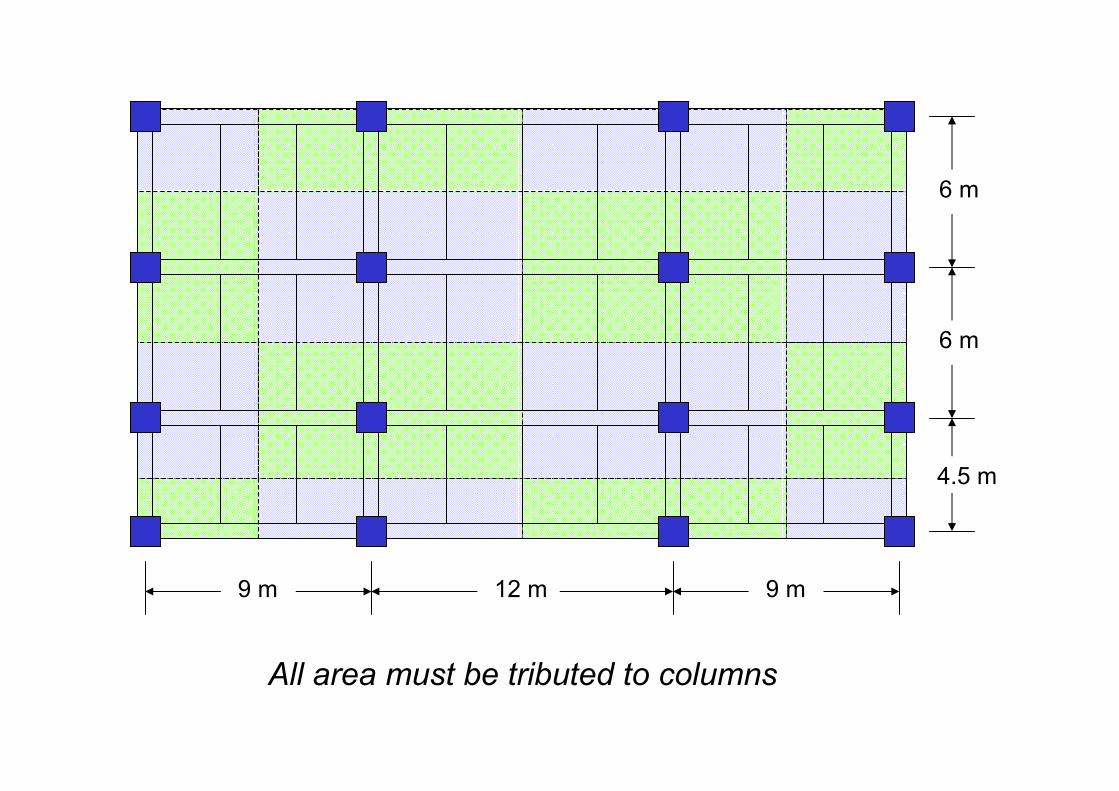
9 m 12 m 9 m
4.5 m
6 m
6 m
All area must be tributed to columns
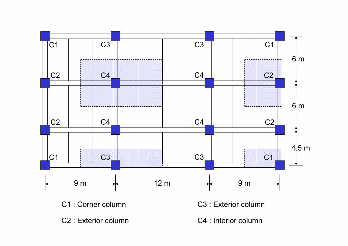
C1
C1 : Corner column
C2
C2 : Exterior column
C3
C3 : Exterior column
C4
C4 : Interior column
9 m 12 m 9 m
4.5 m
6 m
6 m
C1
C1 C1
C2C2
C2
C3
C3C3
C4 C4
C4
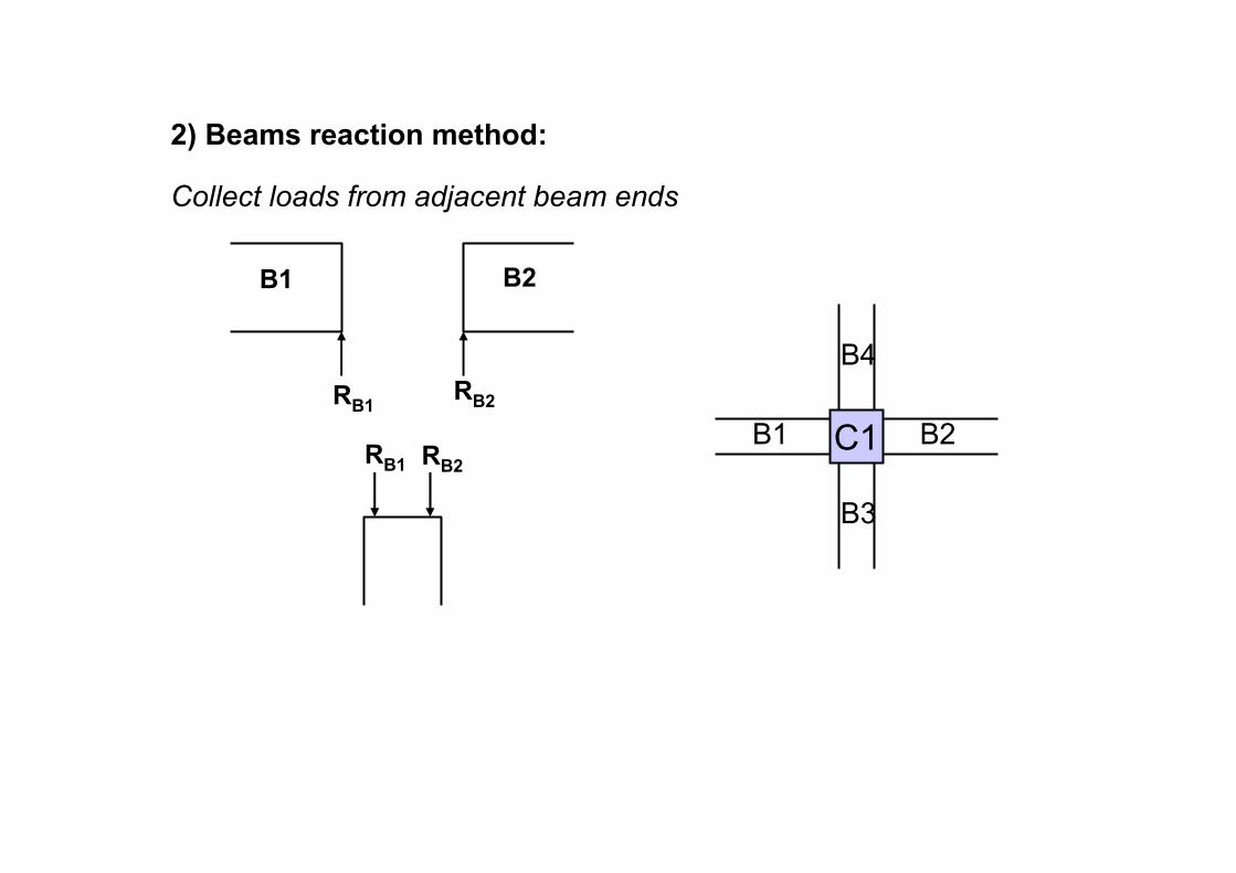
2) Beams reaction method:
B1 B2
RB1
RB1 RB2
RB2
Collect loads from adjacent beam ends
C1B1 B2
B3
B4
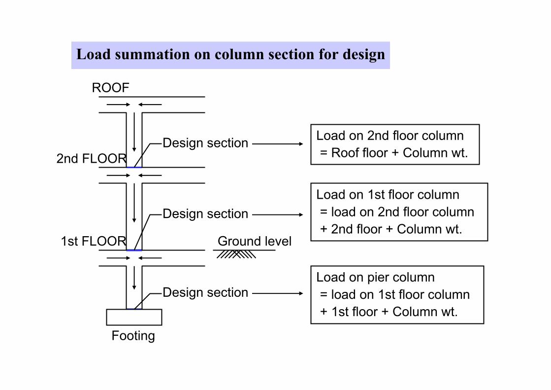
Load summation on column section for design
Design section
Design section
Design section
ROOF
2nd FLOOR
1st FLOOR
Footing
Ground level
Load on pier column
= load on 1st floor column
+ 1st floor + Column wt.
Load on 1st floor column
= load on 2nd floor column
+ 2nd floor + Column wt.
Load on 2nd floor column
= Roof floor + Column wt.
�������������� �������������
���������
������3.50 m
0.3 x 0.3 m
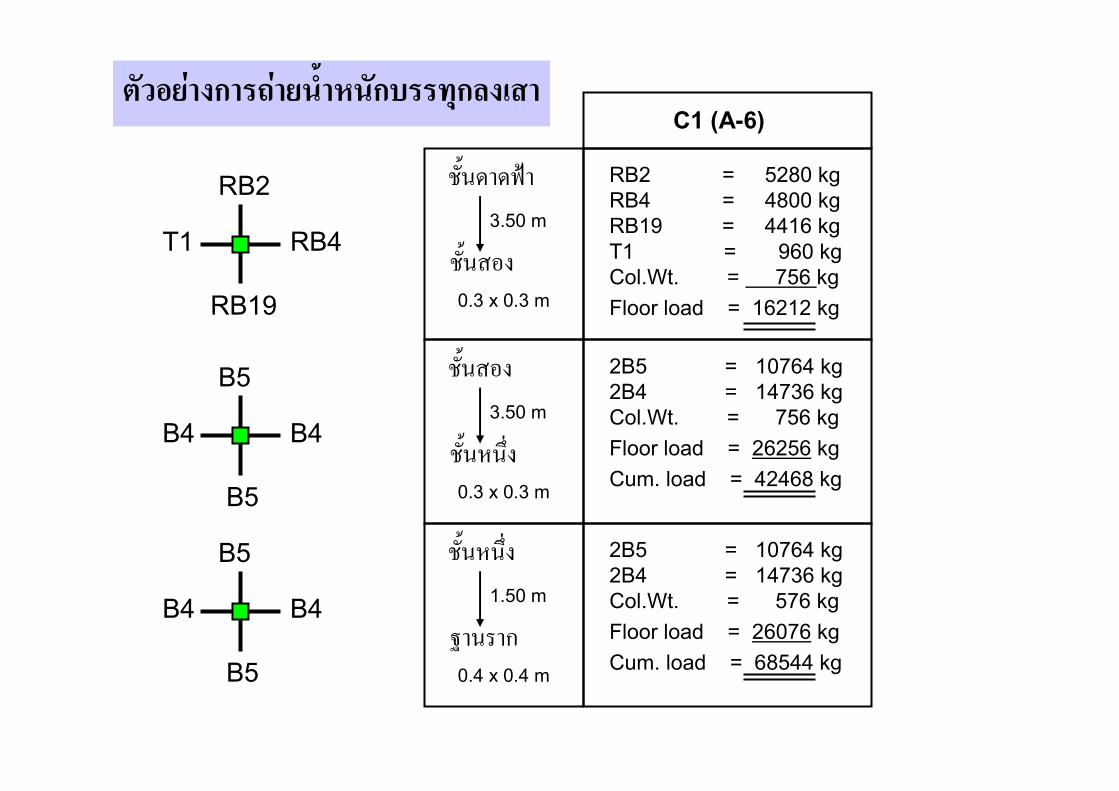
C1 (A-6)
������
���� ����3.50 m
0.3 x 0.3 m
���� ����
������1.50 m
0.4 x 0.4 m
RB2 = 5280 kg
RB4 = 4800 kg
RB19 = 4416 kg
T1 = 960 kg
Col.Wt. = 756 kg
Floor load = 16212 kg
2B5 = 10764 kg
2B4 = 14736 kg
Col.Wt. = 756 kg
Floor load = 26256 kg
Cum. load = 42468 kg
2B5 = 10764 kg
2B4 = 14736 kg
Col.Wt. = 576 kg
Floor load = 26076 kg
Cum. load = 68544 kg
T1
RB2
RB4
RB19
B4
B5
B4
B5
B4
B5
B4
B5
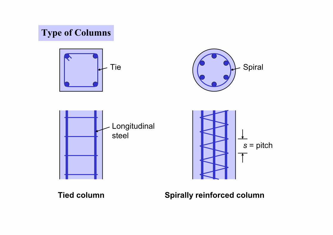
Type of Columns
Tie
Longitudinal
steel
Tied column
Spiral
s = pitch
Spirally reinforced column
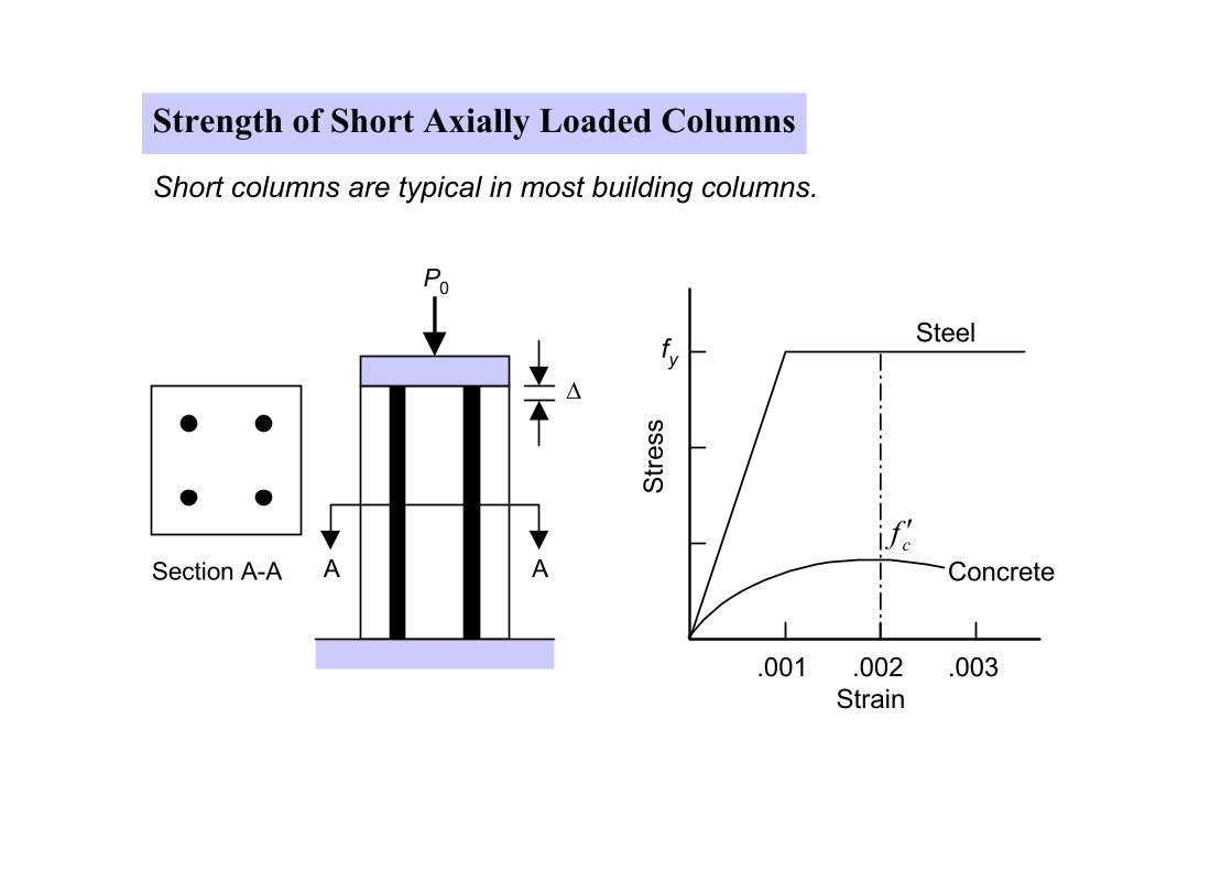
Strength of Short Axially Loaded Columns
Short columns are typical in most building columns.
P0
A A
∆
Section A-A
.001 .002 .003
fy
cf ′
Steel
Concrete
Strain
Stress
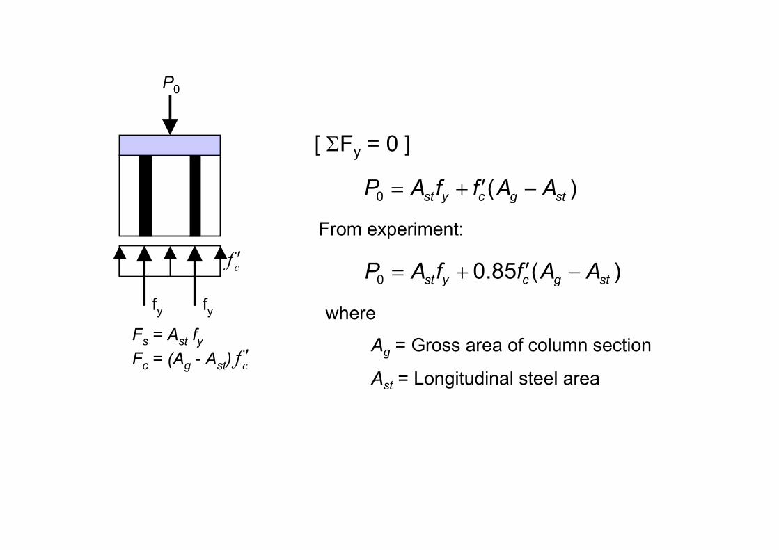
P0
fyfy
cf ′
Fs = Ast fyFc = (Ag - Ast) cf ′
[ ΣFy = 0 ]
0 ( )st y c g stP A f f A A′= + −
From experiment:
0 0.85 ( )st y c g stP A f f A A′= + −
where
Ag = Gross area of column section
Ast = Longitudinal steel area
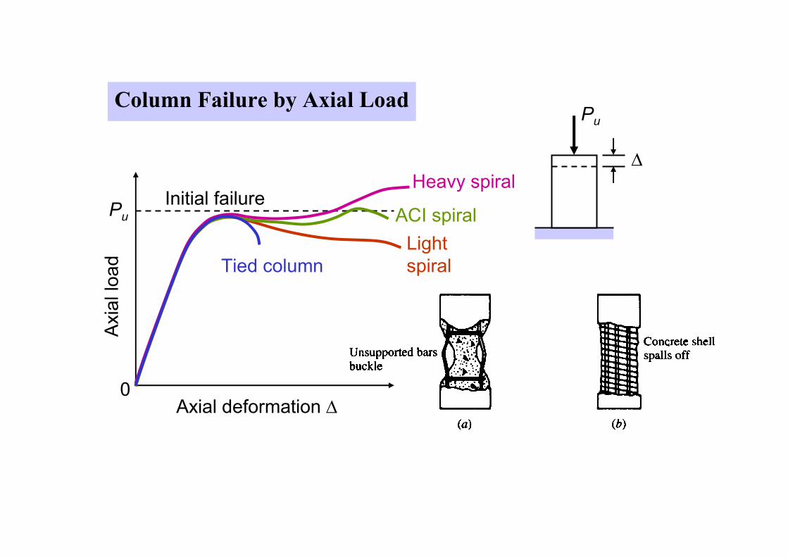
Pu
0Axial deformation ∆
Initial failure
Axial load Tied column
Light
spiral
ACI spiral
Heavy spiral
Column Failure by Axial Load
∆
Pu
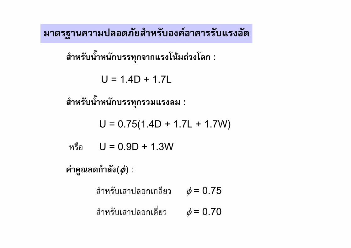
������������� ���������������������������
������������������������������������� :
U = 1.4D + 1.7L
���������������������������� :
U = 0.75(1.4D + 1.7L + 1.7W)
���� U = 0.9D + 1.3W
����"#������(φφφφ) :
��������� ���� ��� φ = 0.75
��������� �������� φ = 0.70
�����������&�'(��
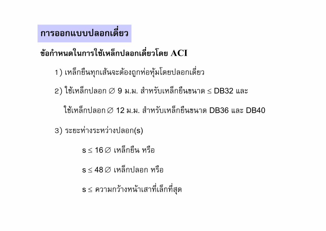
)��������*����*+�&�,���&�'(����� ACI
1) �� ������������������� ��!����"#��� ��������
2) &'��� ��� �� ∅ 9 ".". ������� �����)��� ≤ DB32 * �
&'��� ��� �� ∅ 12 ".". ������� �����)��� DB36 * � DB40
3) �����!������!��� ��(s)
s ≤ 16∅ �� ����� ����
s ≤ 48∅ �� ��� �� ����
s ≤ ,��"���������������� ��������
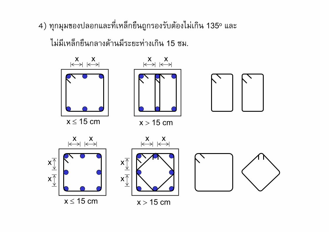
4) ���"�")��� ��* ������ ������ ���������."!��/� 135o * �
."!"��� ������ ������"������!����/� 15 0".
xx
x ≤ 15 cm
xx
x > 15 cm
xx
x ≤ 15 cm
x
x
xx
x > 15 cm
x
x

�����������&�'��
PuInitial shape
Final shapef2
Spiralf2
Increase of compressive strength due to lateral pressure:
24.1f cf f f′= +
Good design: Strength lost by spalling = Strength gain from f2
2( )(0.85 ) (4.1 )g core c coreA A f A f′− = 1
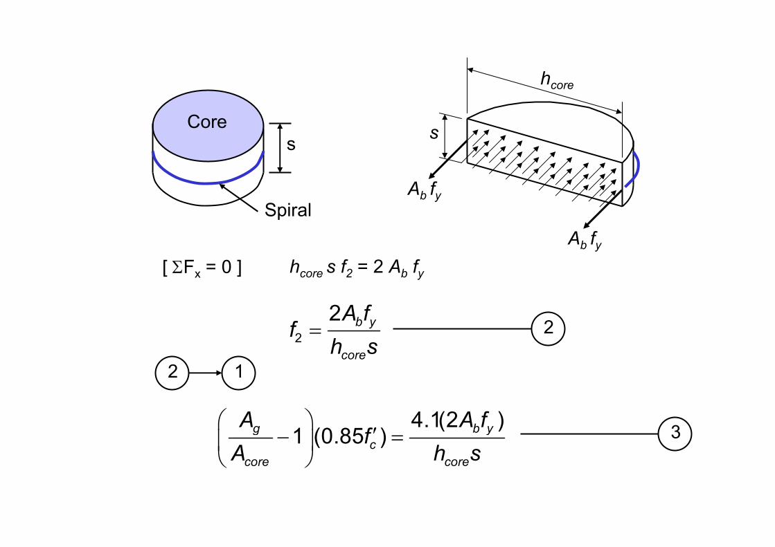
Core
Spiral
s
hcore
Ab fy
Ab fy
s
[ ΣFx = 0 ] hcore s f2 = 2 Ab fy
2
2 b y
core
A ff
h s= 2
12
4.1(2 )1 (0.85 )
g b y
c
core core
A A ff
A h s
′− =
3
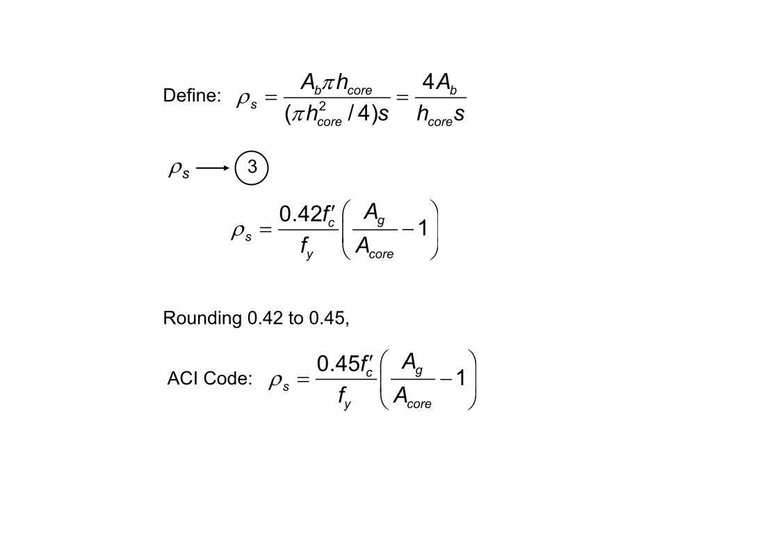
Define:2
4
( / 4)b core b
s
core core
A h A
h s h s
πρ
π= =
ρs 3
0.421
gcs
y core
Af
f Aρ
′= −
Rounding 0.42 to 0.45,
ACI Code:0.45
1gc
s
y core
Af
f Aρ
′= −
)��������*����*+�&�,���&�'��
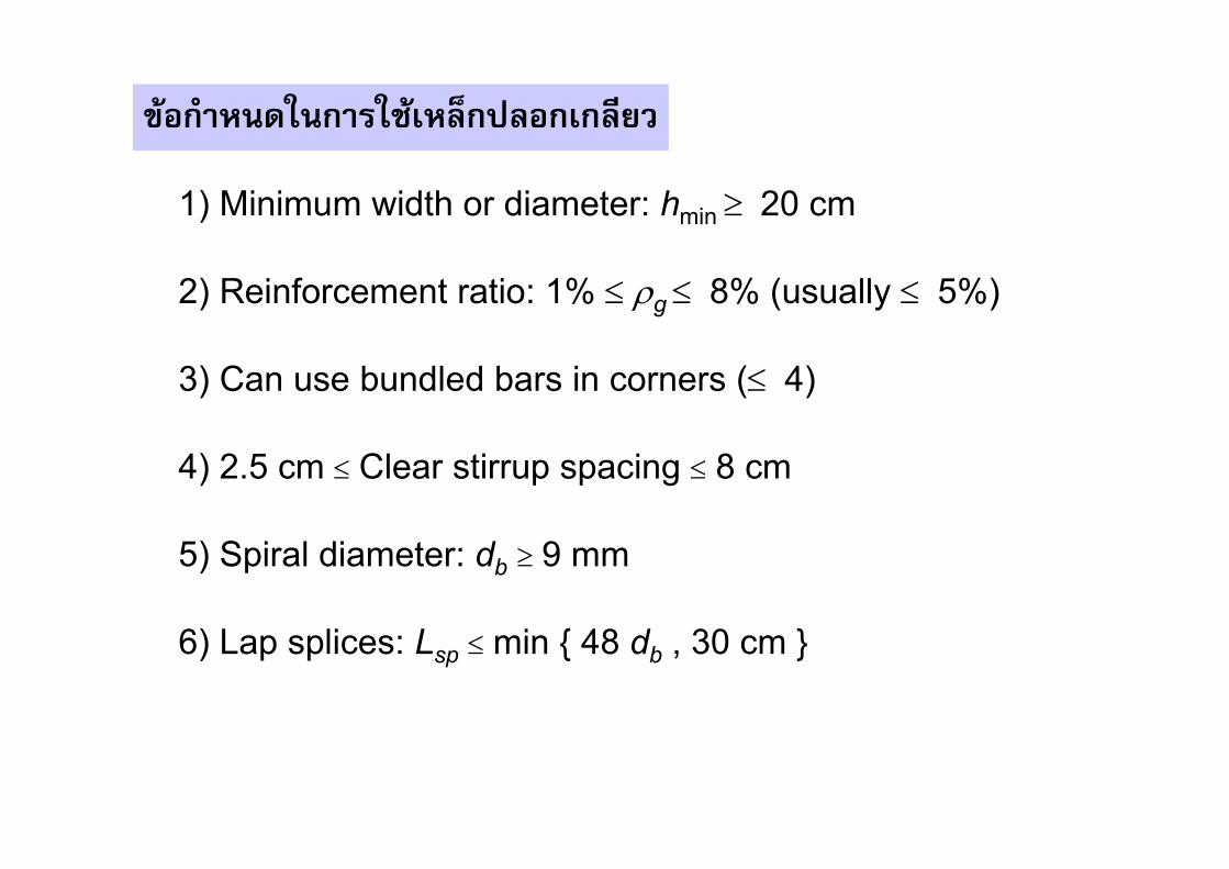
1) Minimum width or diameter: hmin ≥ 20 cm
4) 2.5 cm ≤ Clear stirrup spacing ≤ 8 cm
2) Reinforcement ratio: 1% ≤ ρg ≤ 8% (usually ≤ 5%)
3) Can use bundled bars in corners (≤ 4)
5) Spiral diameter: db ≥ 9 mm
6) Lap splices: Lsp ≤min { 48 db , 30 cm }
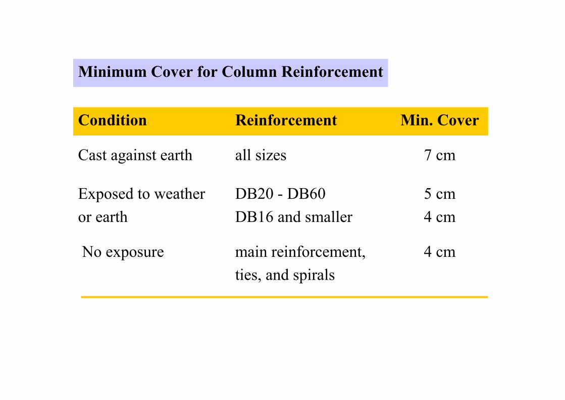
Minimum Cover for Column Reinforcement
Condition
Cast against earth
Exposed to weather
or earth
No exposure
Reinforcement
all sizes
DB20 - DB60
DB16 and smaller
main reinforcement,
ties, and spirals
Min. Cover
7 cm
5 cm
4 cm
4 cm
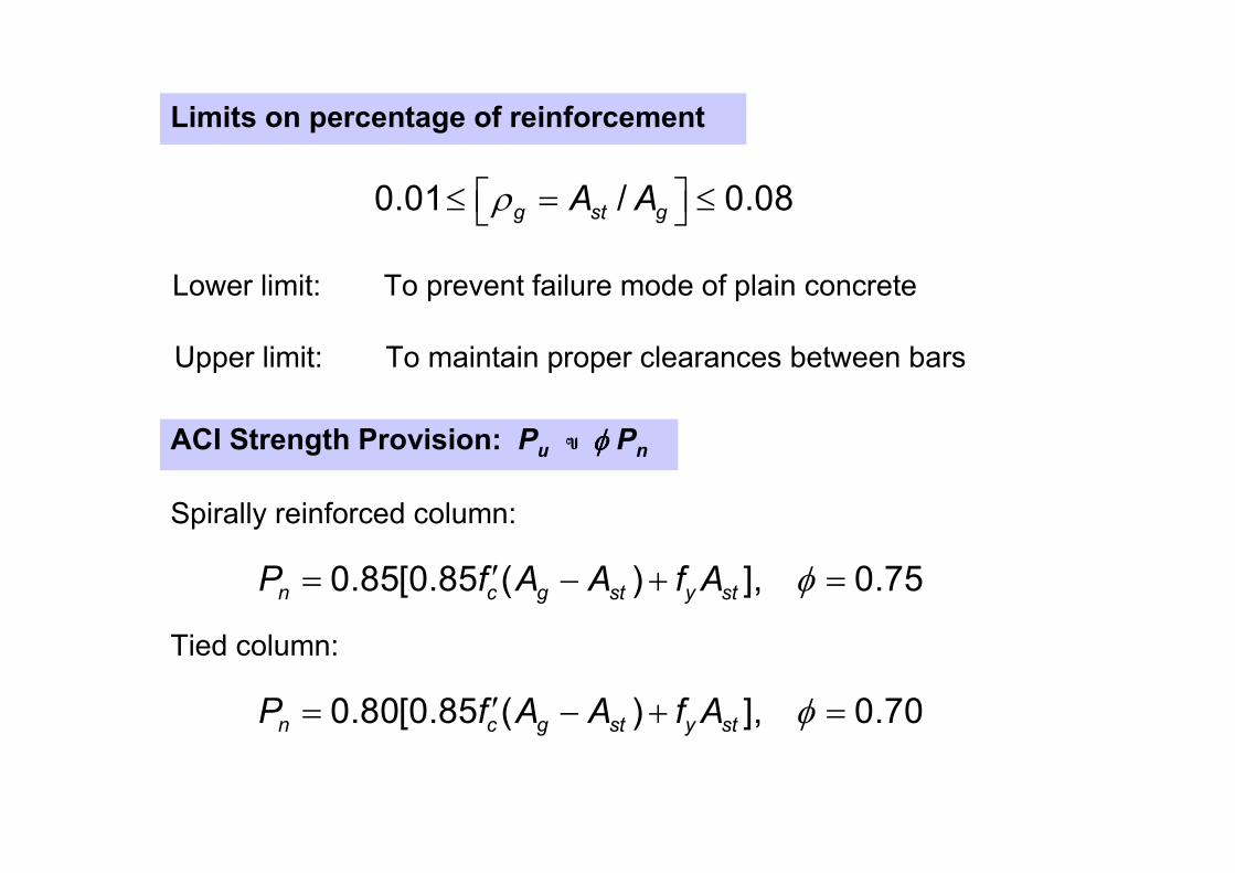
Limits on percentage of reinforcement
0.01 / 0.08g st gA Aρ ≤ = ≤
Lower limit: To prevent failure mode of plain concrete
Upper limit: To maintain proper clearances between bars
ACI Strength Provision: Pu � φφφφ P
n
Spirally reinforced column:
0.85[0.85 ( ) ], 0.75n c g st y stP f A A f A φ′= − + =
Tied column:
0.80[0.85 ( ) ], 0.70n c g st y stP f A A f A φ′= − + =
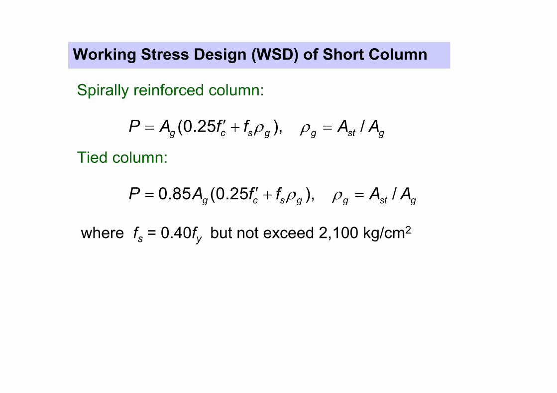
Working Stress Design (WSD) of Short Column
Spirally reinforced column:
ρ ρ′= + =(0.25 ), /g c s g g st gP A f f A A
Tied column:
ρ ρ′= + =0.85 (0.25 ), /g c s g g st gP A f f A A
where fs = 0.40fy but not exceed 2,100 kg/cm2

Length Effects
ACI permits neglect of length effect when
1
2
34 12 for braced systemukL M
r M≤ −
where (34 - 12M1/M2) may not exceed 40
M1 = The smaller bending moment
M2 = The larger bending moment
M1/M2 is positive for single curvature
and negative for double curvature
22 for unbraced systemukL
r≤
M1
M2
-
M1
M2
+
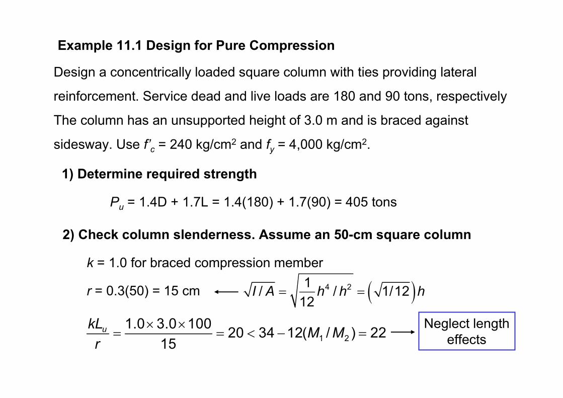
Example 11.1 Design for Pure Compression
Design a concentrically loaded square column with ties providing lateral
reinforcement. Service dead and live loads are 180 and 90 tons, respectively
The column has an unsupported height of 3.0 m and is braced against
sidesway. Use f’c = 240 kg/cm2 and fy = 4,000 kg/cm
2.
1) Determine required strength
Pu = 1.4D + 1.7L = 1.4(180) + 1.7(90) = 405 tons
2) Check column slenderness. Assume an 50-cm square column
k = 1.0 for braced compression member
r = 0.3(50) = 15 cm ( )4 21/ / 1/12
12I A h h h= =
1 2
1.0 3.0 10020 34 12( / ) 22
15ukL
M Mr
× ×= = < − =
Neglect length
effects

3) Design for column reinforcement
Required Pn = Pu/φ = 405/0.70 = 578.6 ton
for tied column: 0.80[0.85 ( ) ]n c g st y stP f A A f A′= − +
578.6 × 1,000 = 0.80(0.85×240(50×50 - Ast) + 4,000Ast)
Ast = 56.2 cm2
USE 12DB25 (Ast = 58.9 cm2, ρg = 2.36%)
4) Select lateral reinforcement
USE RB9 ties with DB25 longitudinal bars
Spacing not greater than: 16 (2.5) = 40 cm
48 (0.9) = 43.2 cm
column size = 50 cm
USE RB9 @ 40 cm
50 cm
50cm 12DB25