Embed Size (px)
Citation preview
1/72 AZ Model Kawasaki Ki-78
Name: Alexander Nam Tran
Country: Australia, Sydney
Model Scale: 1/72
Kit Maker: AZ Model
Greetings again everyone,
I’m Alex Tran from Sydney Australia and here I present my 13th legitimate and completed
build and second Imperial Japanese Army aircraft ever since my entry in Arawasi’s Japanese
Aircraft Online Model Contest 004, Tateo Katou’s Ki-43-I. This build was started in December
after my intense work schedule started to ease up for the year.
I had purchased this kit around mid-2016, the time when I started to take this hobby
seriously, seeing it as an unusual, unique and quick addition to my collection. However, I
was very wrong about the “quick” part, realising that there were several issues present with
this kit as you will see. Feeling daunted and not knowing how to fix these problems nicely at
the time, the kit was left alone in the stash ever since until now.
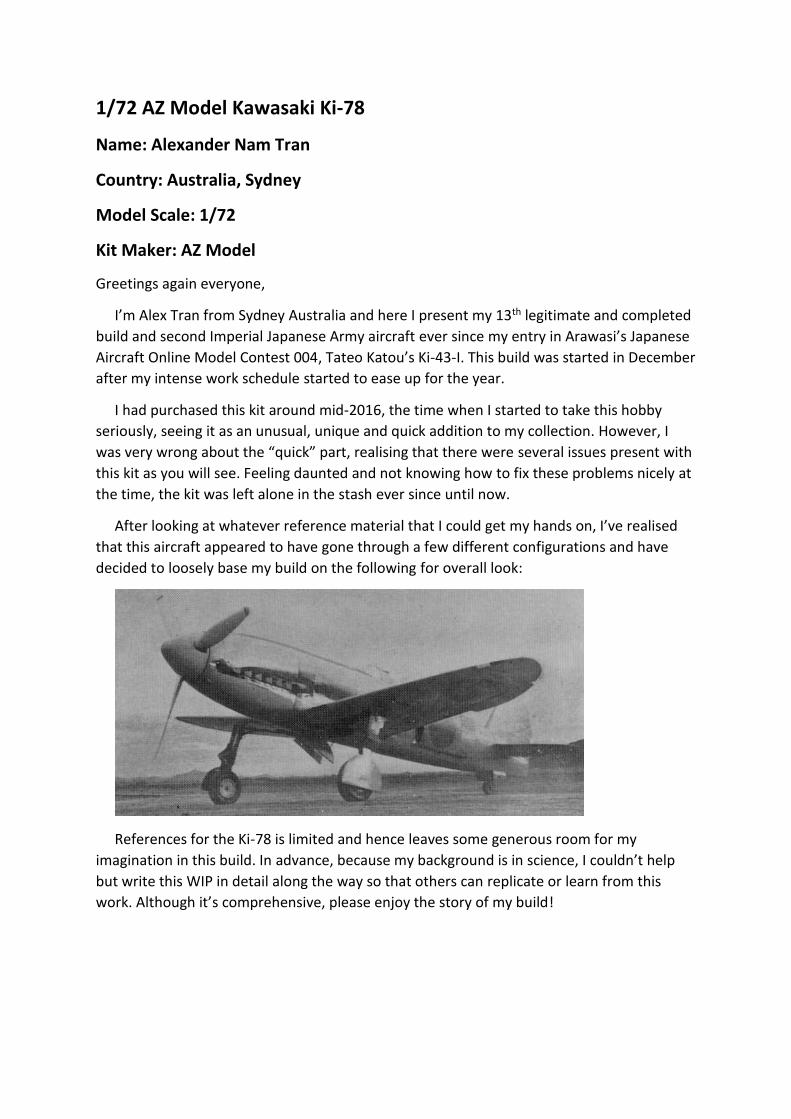
After looking at whatever reference material that I could get my hands on, I’ve realised
that this aircraft appeared to have gone through a few different configurations and have
decided to loosely base my build on the following for overall look:
References for the Ki-78 is limited and hence leaves some generous room for my
imagination in this build. In advance, because my background is in science, I couldn’t help
but write this WIP in detail along the way so that others can replicate or learn from this
work. Although it’s comprehensive, please enjoy the story of my build!
Work in Progress:
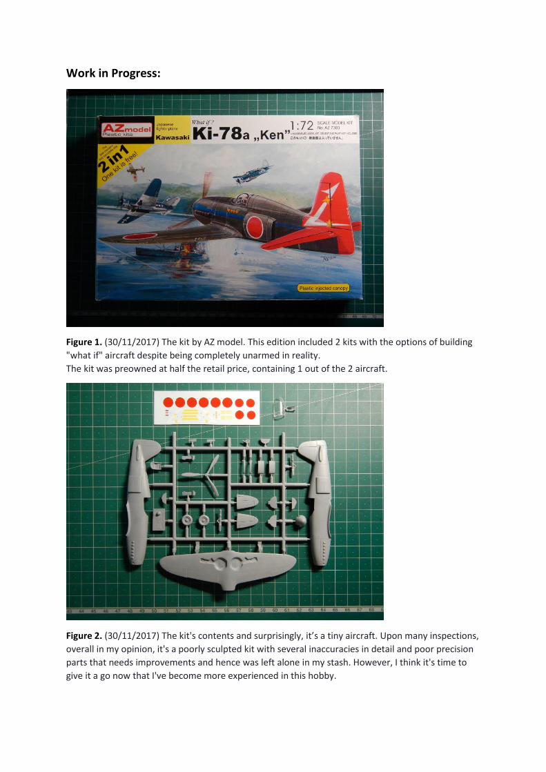
Figure 1. (30/11/2017) The kit by AZ model. This edition included 2 kits with the options of building
"what if" aircraft despite being completely unarmed in reality.
The kit was preowned at half the retail price, containing 1 out of the 2 aircraft.
Figure 2. (30/11/2017) The kit's contents and surprisingly, it’s a tiny aircraft. Upon many inspections,
overall in my opinion, it's a poorly sculpted kit with several inaccuracies in detail and poor precision
parts that needs improvements and hence was left alone in my stash. However, I think it's time to
give it a go now that I've become more experienced in this hobby.
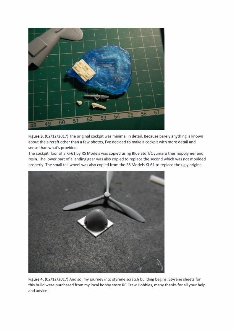
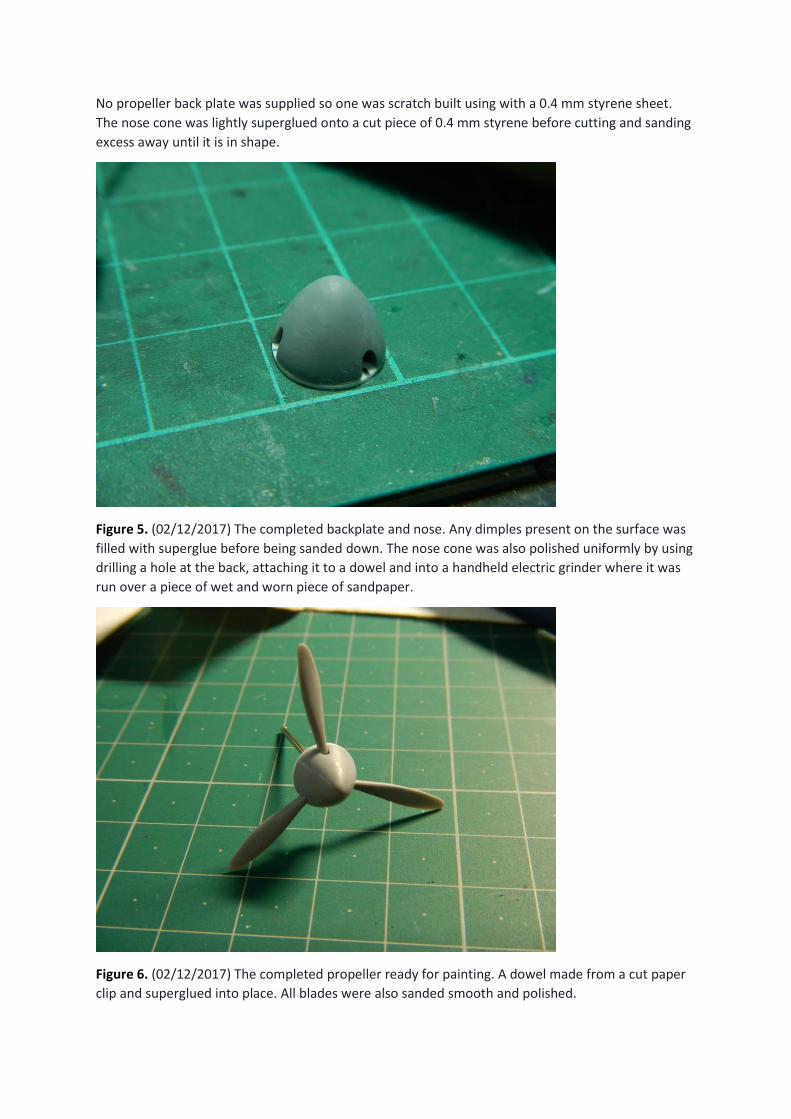
Figure 3. (02/12/2017) The original cockpit was minimal in detail. Because barely anything is known
about the aircraft other than a few photos, I've decided to make a cockpit with more detail and
sense than what's provided.
The cockpit floor of a Ki-61 by RS Models was copied using Blue Stuff/Oyumaru thermopolymer and
resin. The lower part of a landing gear was also copied to replace the second which was not moulded
properly. The small tail wheel was also copied from the RS Models Ki-61 to replace the ugly original.
Figure 4. (02/12/2017) And so, my journey into styrene scratch building begins. Styrene sheets for
this build were purchased from my local hobby store RC Crew Hobbies, many thanks for all your help
and advice!
No propeller back plate was supplied so one was scratch built using with a 0.4 mm styrene sheet.
The nose cone was lightly superglued onto a cut piece of 0.4 mm styrene before cutting and sanding
excess away until it is in shape.
Figure 5. (02/12/2017) The completed backplate and nose. Any dimples present on the surface was
filled with superglue before being sanded down. The nose cone was also polished uniformly by using
drilling a hole at the back, attaching it to a dowel and into a handheld electric grinder where it was
run over a piece of wet and worn piece of sandpaper.
Figure 6. (02/12/2017) The completed propeller ready for painting. A dowel made from a cut paper
clip and superglued into place. All blades were also sanded smooth and polished.
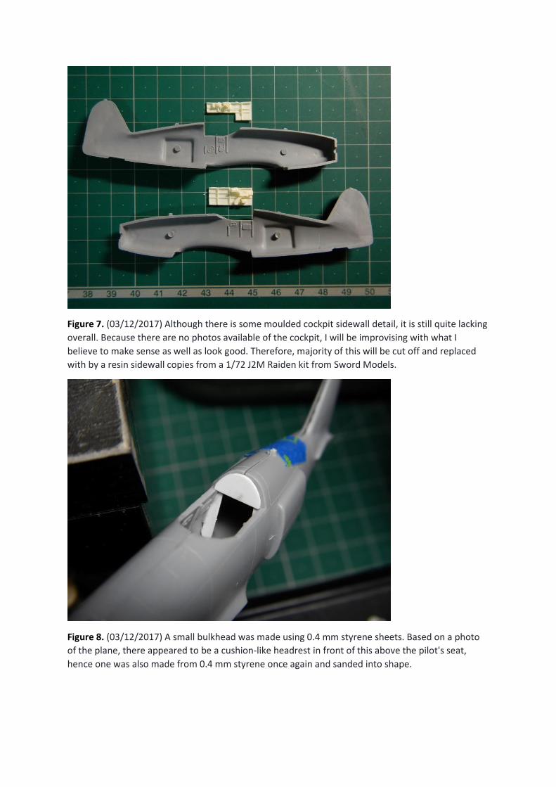
Figure 7. (03/12/2017) Although there is some moulded cockpit sidewall detail, it is still quite lacking
overall. Because there are no photos available of the cockpit, I will be improvising with what I
believe to make sense as well as look good. Therefore, majority of this will be cut off and replaced
with by a resin sidewall copies from a 1/72 J2M Raiden kit from Sword Models.
Figure 8. (03/12/2017) A small bulkhead was made using 0.4 mm styrene sheets. Based on a photo
of the plane, there appeared to be a cushion-like headrest in front of this above the pilot's seat,
hence one was also made from 0.4 mm styrene once again and sanded into shape.
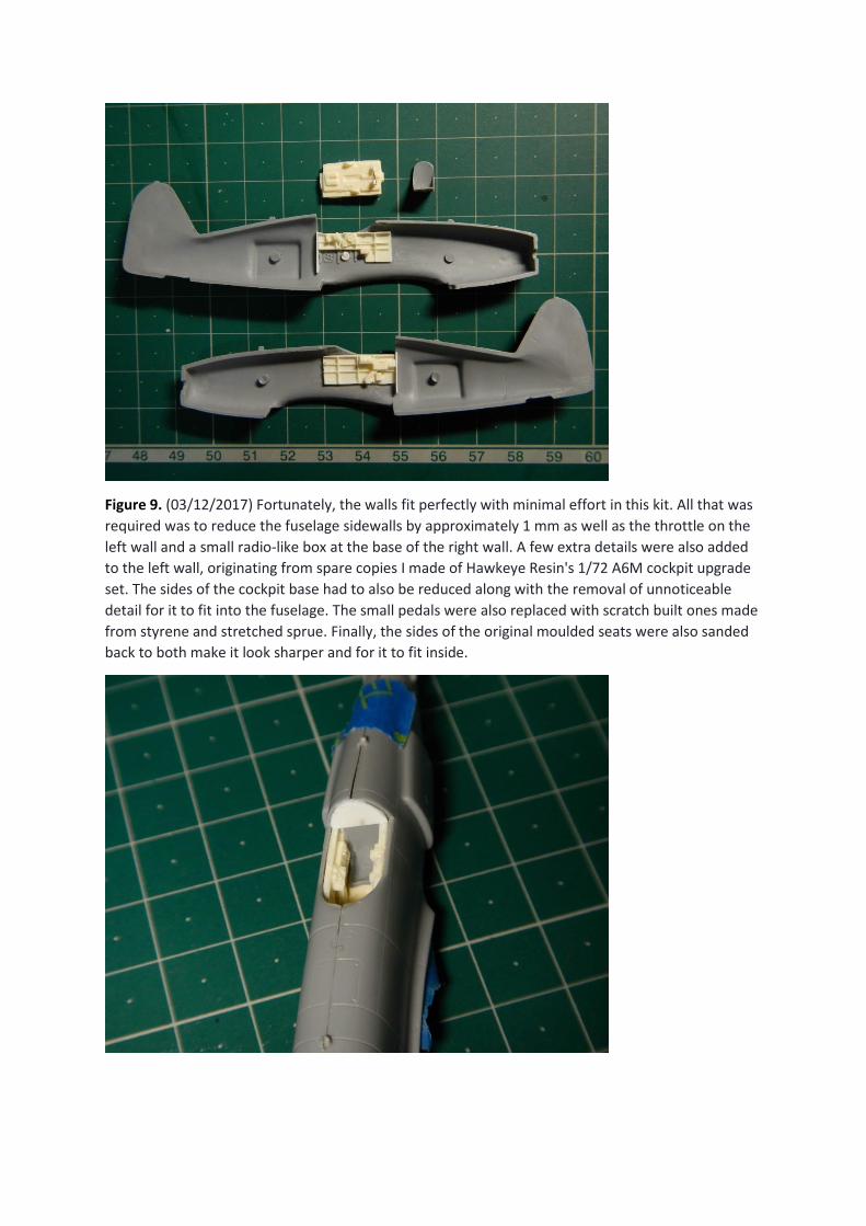
Figure 9. (03/12/2017) Fortunately, the walls fit perfectly with minimal effort in this kit. All that was
required was to reduce the fuselage sidewalls by approximately 1 mm as well as the throttle on the
left wall and a small radio-like box at the base of the right wall. A few extra details were also added
to the left wall, originating from spare copies I made of Hawkeye Resin's 1/72 A6M cockpit upgrade
set. The sides of the cockpit base had to also be reduced along with the removal of unnoticeable
detail for it to fit into the fuselage. The small pedals were also replaced with scratch built ones made
from styrene and stretched sprue. Finally, the sides of the original moulded seats were also sanded
back to both make it look sharper and for it to fit inside.
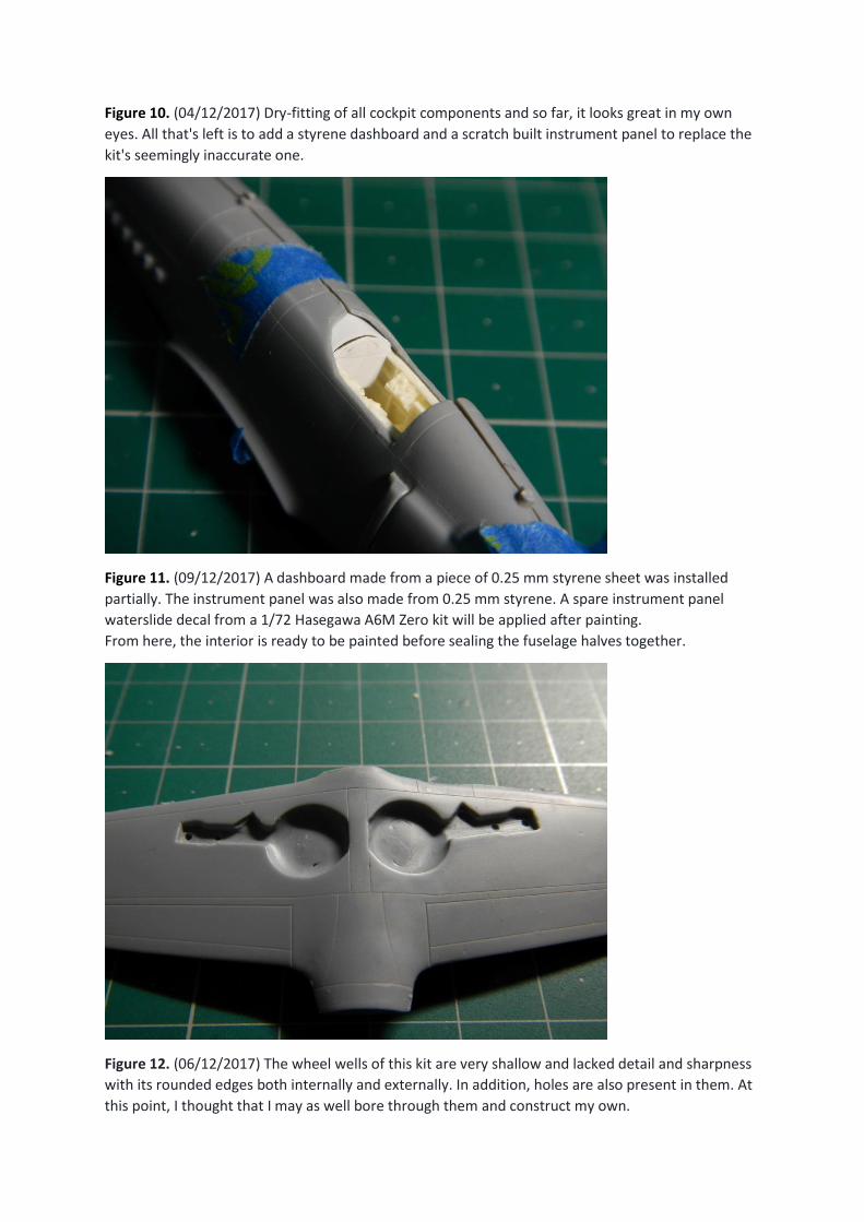
Figure 10. (04/12/2017) Dry-fitting of all cockpit components and so far, it looks great in my own
eyes. All that's left is to add a styrene dashboard and a scratch built instrument panel to replace the
kit's seemingly inaccurate one.
Figure 11. (09/12/2017) A dashboard made from a piece of 0.25 mm styrene sheet was installed
partially. The instrument panel was also made from 0.25 mm styrene. A spare instrument panel
waterslide decal from a 1/72 Hasegawa A6M Zero kit will be applied after painting.
From here, the interior is ready to be painted before sealing the fuselage halves together.
Figure 12. (06/12/2017) The wheel wells of this kit are very shallow and lacked detail and sharpness
with its rounded edges both internally and externally. In addition, holes are also present in them. At
this point, I thought that I may as well bore through them and construct my own.
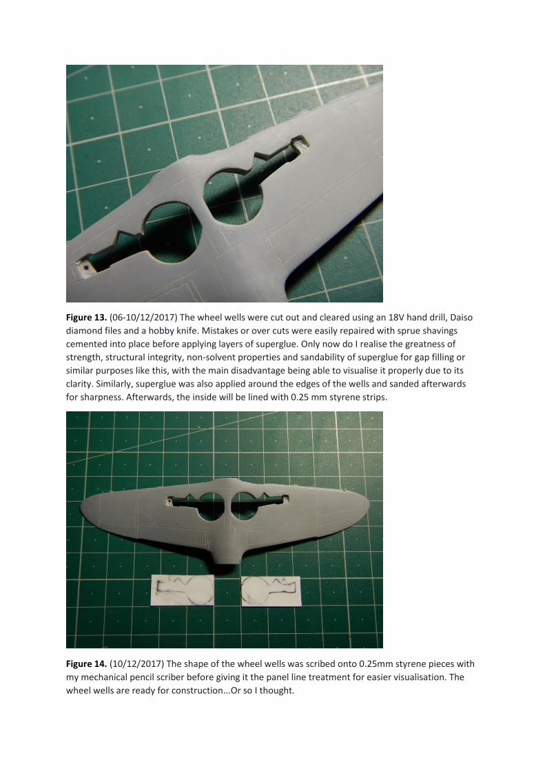
Figure 13. (06-10/12/2017) The wheel wells were cut out and cleared using an 18V hand drill, Daiso
diamond files and a hobby knife. Mistakes or over cuts were easily repaired with sprue shavings
cemented into place before applying layers of superglue. Only now do I realise the greatness of
strength, structural integrity, non-solvent properties and sandability of superglue for gap filling or
similar purposes like this, with the main disadvantage being able to visualise it properly due to its
clarity. Similarly, superglue was also applied around the edges of the wells and sanded afterwards
for sharpness. Afterwards, the inside will be lined with 0.25 mm styrene strips.
Figure 14. (10/12/2017) The shape of the wheel wells was scribed onto 0.25mm styrene pieces with
my mechanical pencil scriber before giving it the panel line treatment for easier visualisation. The
wheel wells are ready for construction...Or so I thought.
Upon closer inspection, they were asymmetrical and I didn't know despite trying to shape it.
After some measurements and comparisons to a set of detailed blueprints by Minoru Matsuda, it
turns out that the whole wing was asymmetrical with the outer right-wing details being off and
pushed inward by 1 mm to scale. This ultimately resulted in the right wheel well being 1 mm shorter
as well as the flaps.
At this point, I can say that this kit is very poor overall. However, that shouldn't be able stop any
modeller for in this hobby, anything can be fixed with time, patience and effort.
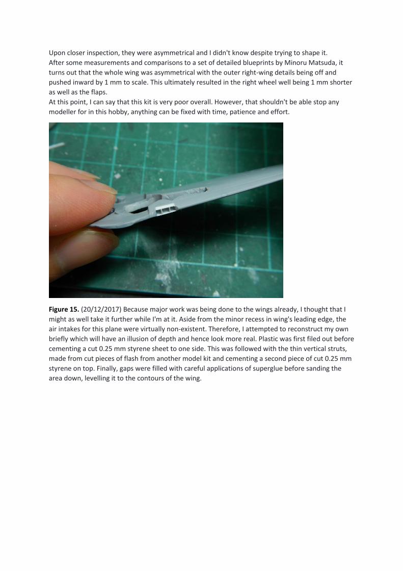
Figure 15. (20/12/2017) Because major work was being done to the wings already, I thought that I
might as well take it further while I'm at it. Aside from the minor recess in wing's leading edge, the
air intakes for this plane were virtually non-existent. Therefore, I attempted to reconstruct my own
briefly which will have an illusion of depth and hence look more real. Plastic was first filed out before
cementing a cut 0.25 mm styrene sheet to one side. This was followed with the thin vertical struts,
made from cut pieces of flash from another model kit and cementing a second piece of cut 0.25 mm
styrene on top. Finally, gaps were filled with careful applications of superglue before sanding the
area down, levelling it to the contours of the wing.
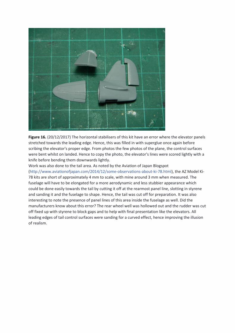
Figure 16. (20/12/2017) The horizontal stabilisers of this kit have an error where the elevator panels
stretched towards the leading edge. Hence, this was filled in with superglue once again before
scribing the elevator's proper edge. From photos the few photos of the plane, the control surfaces
were bent whilst on landed. Hence to copy the photo, the elevator's lines were scored lightly with a
knife before bending them downwards lightly.
Work was also done to the tail area. As noted by the Aviation of Japan Blogspot
(http://www.aviationofjapan.com/2014/12/some-observations-about-ki-78.html), the AZ Model Ki-
78 kits are short of approximately 4 mm to scale, with mine around 3 mm when measured. The
fuselage will have to be elongated for a more aerodynamic and less stubbier appearance which
could be done easily towards the tail by cutting it off at the rearmost panel line, slotting in styrene
and sanding it and the fuselage to shape. Hence, the tail was cut off for preparation. It was also
interesting to note the presence of panel lines of this area inside the fuselage as well. Did the
manufacturers know about this error? The rear wheel well was hollowed out and the rudder was cut
off fixed up with styrene to block gaps and to help with final presentation like the elevators. All
leading edges of tail control surfaces were sanding for a curved effect, hence improving the illusion
of realism.
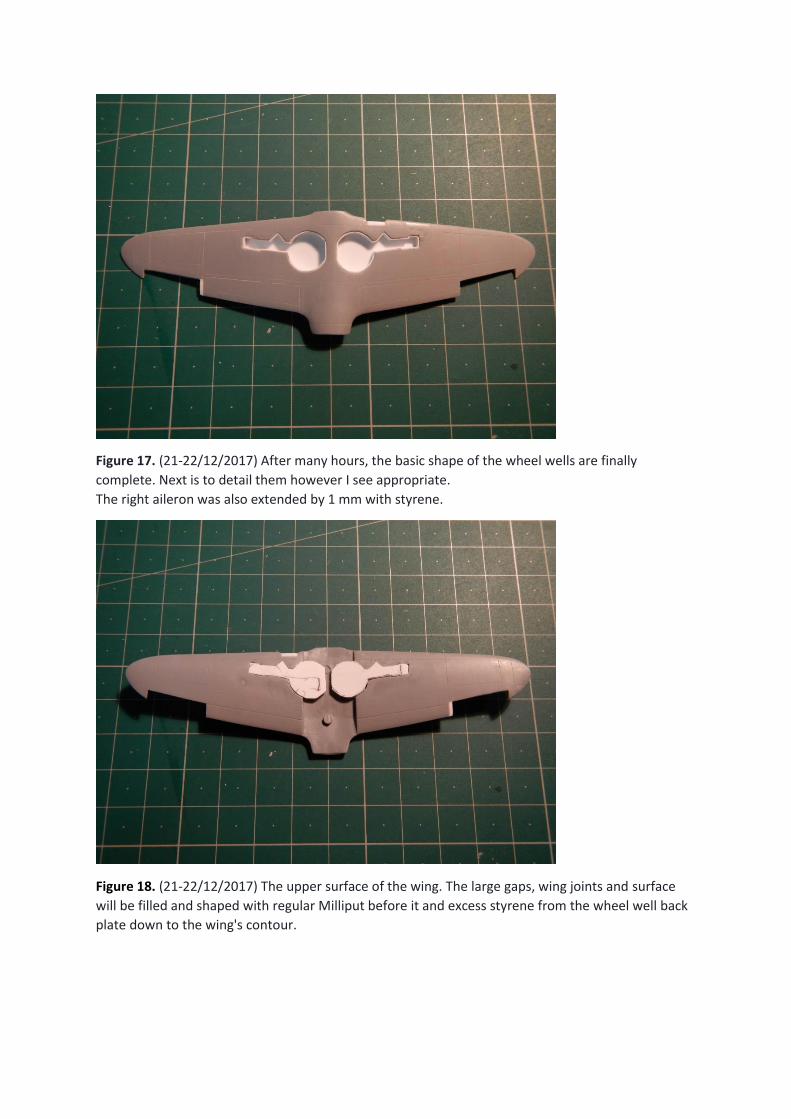
Figure 17. (21-22/12/2017) After many hours, the basic shape of the wheel wells are finally
complete. Next is to detail them however I see appropriate.
The right aileron was also extended by 1 mm with styrene.
Figure 18. (21-22/12/2017) The upper surface of the wing. The large gaps, wing joints and surface
will be filled and shaped with regular Milliput before it and excess styrene from the wheel well back
plate down to the wing's contour.
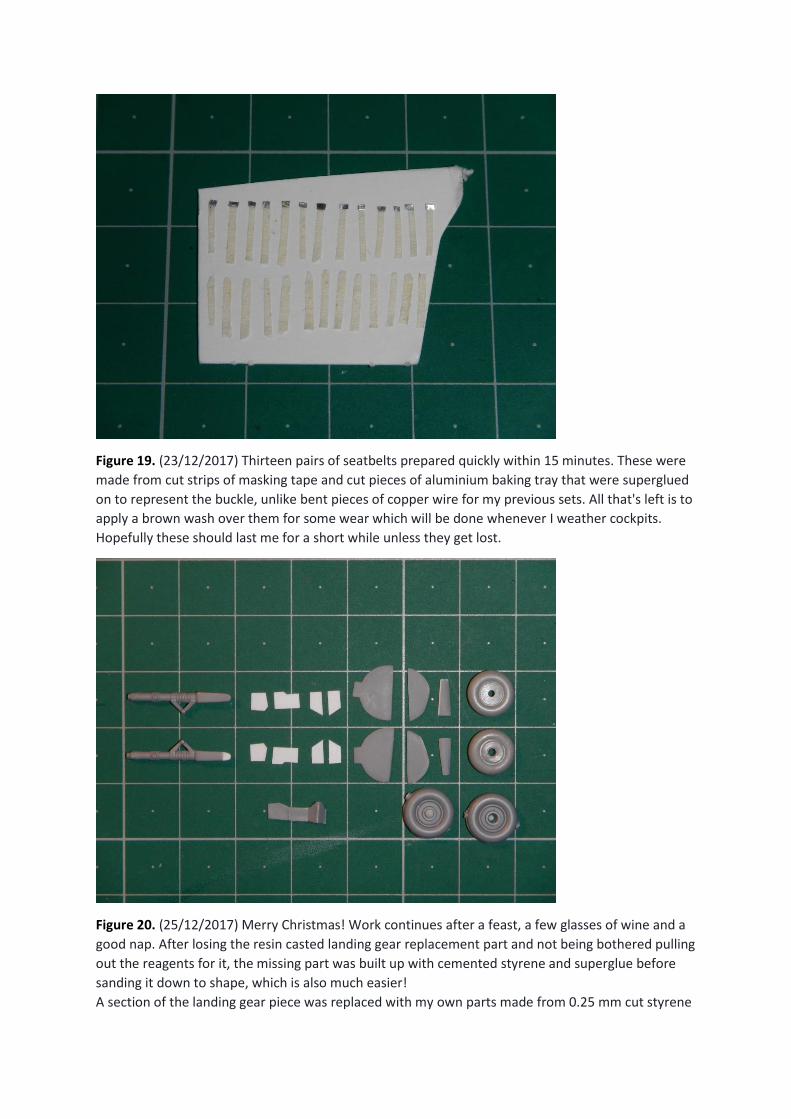
Figure 19. (23/12/2017) Thirteen pairs of seatbelts prepared quickly within 15 minutes. These were
made from cut strips of masking tape and cut pieces of aluminium baking tray that were superglued
on to represent the buckle, unlike bent pieces of copper wire for my previous sets. All that's left is to
apply a brown wash over them for some wear which will be done whenever I weather cockpits.
Hopefully these should last me for a short while unless they get lost.
Figure 20. (25/12/2017) Merry Christmas! Work continues after a feast, a few glasses of wine and a
good nap. After losing the resin casted landing gear replacement part and not being bothered pulling
out the reagents for it, the missing part was built up with cemented styrene and superglue before
sanding it down to shape, which is also much easier!
A section of the landing gear piece was replaced with my own parts made from 0.25 mm cut styrene
while the original pieces of the wheel sections was sanded down to similar a similar thickness. These
parts were also made from cut pieces of aluminium baking tray, thinking it would be similar to
photoetch but their downside was their maleability which would cause trouble when masking. The
replacement pieces were lost a few times and were reprepared. Scatterbrained me…
The original wheels are a poor representation of the real thing from photos. Hence, these were
replaced with a spair pair of A6M wheels from a Hasegawa A6M2-N kit.
Pieces on the left are the originals for comparison with the replacements.
All pieces here are ready for painting.
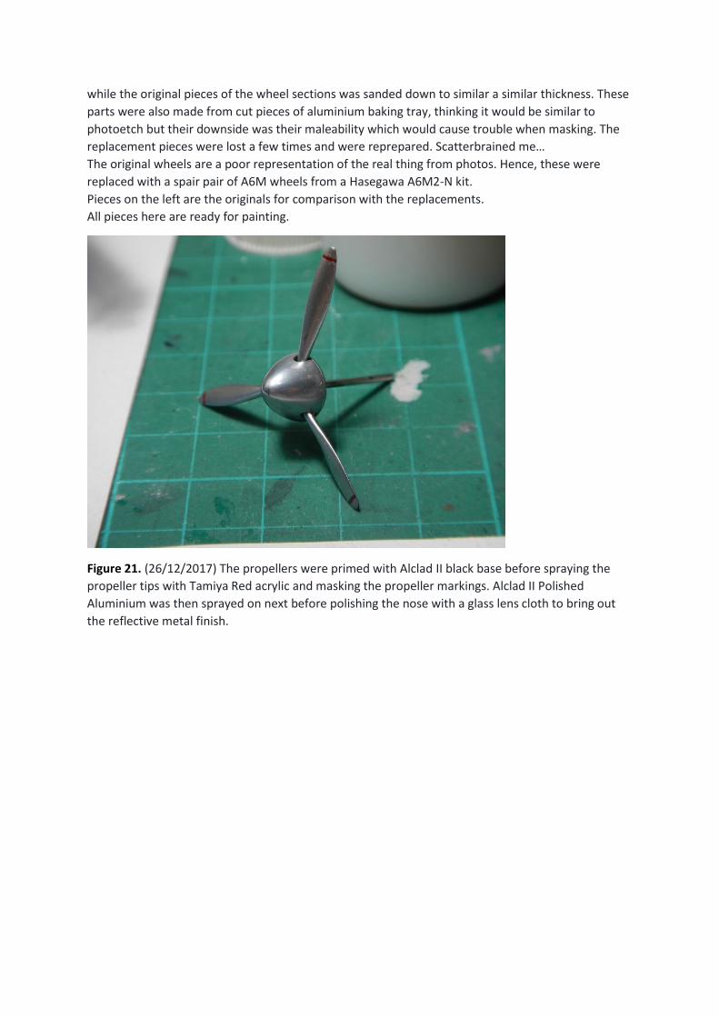
Figure 21. (26/12/2017) The propellers were primed with Alclad II black base before spraying the
propeller tips with Tamiya Red acrylic and masking the propeller markings. Alclad II Polished
Aluminium was then sprayed on next before polishing the nose with a glass lens cloth to bring out
the reflective metal finish.
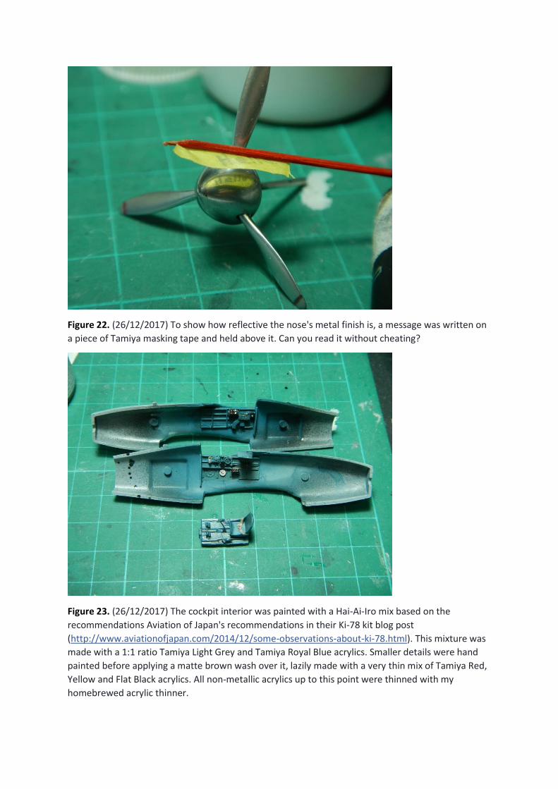
Figure 22. (26/12/2017) To show how reflective the nose's metal finish is, a message was written on
a piece of Tamiya masking tape and held above it. Can you read it without cheating?
Figure 23. (26/12/2017) The cockpit interior was painted with a Hai-Ai-Iro mix based on the
recommendations Aviation of Japan's recommendations in their Ki-78 kit blog post
(http://www.aviationofjapan.com/2014/12/some-observations-about-ki-78.html). This mixture was
made with a 1:1 ratio Tamiya Light Grey and Tamiya Royal Blue acrylics. Smaller details were hand
painted before applying a matte brown wash over it, lazily made with a very thin mix of Tamiya Red,
Yellow and Flat Black acrylics. All non-metallic acrylics up to this point were thinned with my
homebrewed acrylic thinner.
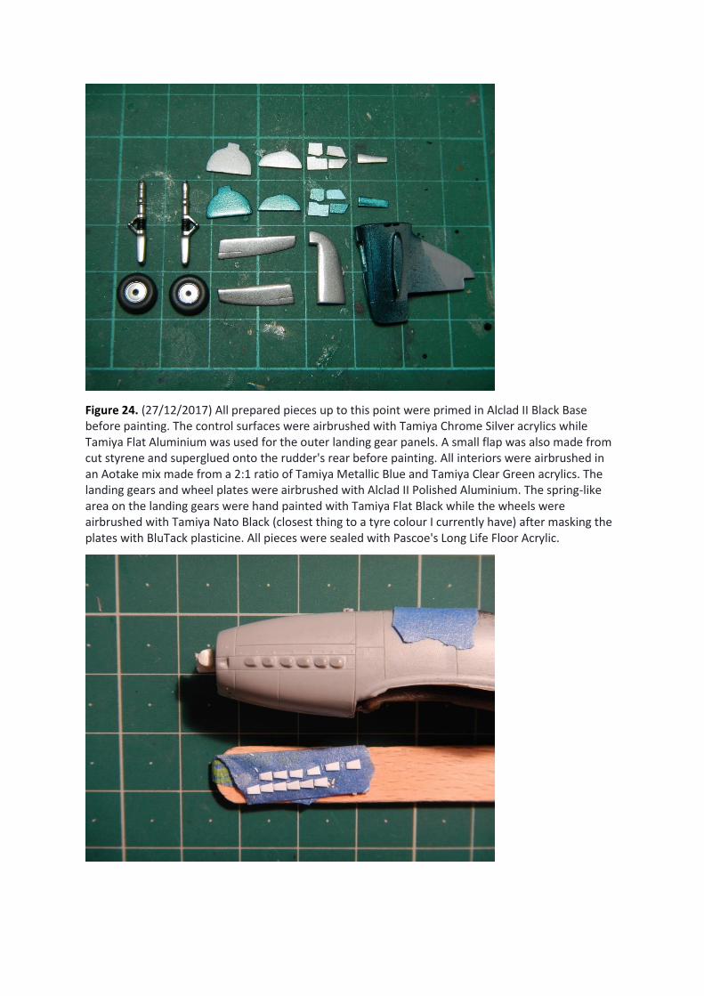
Figure 24. (27/12/2017) All prepared pieces up to this point were primed in Alclad II Black Base before painting. The control surfaces were airbrushed with Tamiya Chrome Silver acrylics while Tamiya Flat Aluminium was used for the outer landing gear panels. A small flap was also made from cut styrene and superglued onto the rudder's rear before painting. All interiors were airbrushed in an Aotake mix made from a 2:1 ratio of Tamiya Metallic Blue and Tamiya Clear Green acrylics. The landing gears and wheel plates were airbrushed with Alclad II Polished Aluminium. The spring-like area on the landing gears were hand painted with Tamiya Flat Black while the wheels were airbrushed with Tamiya Nato Black (closest thing to a tyre colour I currently have) after masking the plates with BluTack plasticine. All pieces were sealed with Pascoe's Long Life Floor Acrylic.
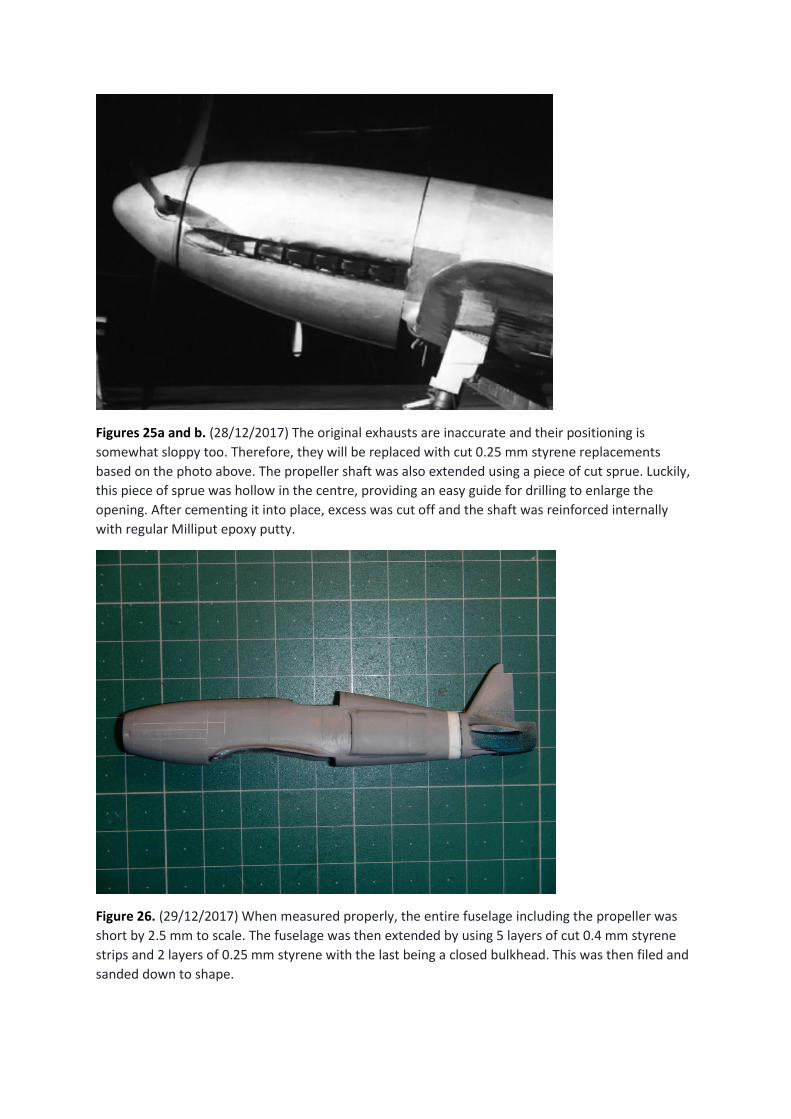
Figures 25a and b. (28/12/2017) The original exhausts are inaccurate and their positioning is
somewhat sloppy too. Therefore, they will be replaced with cut 0.25 mm styrene replacements
based on the photo above. The propeller shaft was also extended using a piece of cut sprue. Luckily,
this piece of sprue was hollow in the centre, providing an easy guide for drilling to enlarge the
opening. After cementing it into place, excess was cut off and the shaft was reinforced internally
with regular Milliput epoxy putty.
Figure 26. (29/12/2017) When measured properly, the entire fuselage including the propeller was
short by 2.5 mm to scale. The fuselage was then extended by using 5 layers of cut 0.4 mm styrene
strips and 2 layers of 0.25 mm styrene with the last being a closed bulkhead. This was then filed and
sanded down to shape.
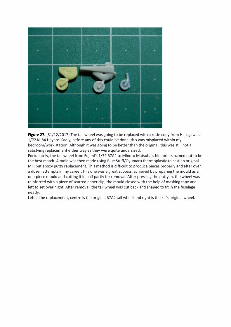
Figure 27. (31/12/2017) The tail wheel was going to be replaced with a resin copy from Hasegawa's 1/72 Ki-84 Hayate. Sadly, before any of this could be done, this was misplaced within my bedroom/work station. Although it was going to be better than the original, this was still not a satisfying replacement either way as they were quite undersized. Fortunately, the tail wheel from Fujimi's 1/72 B7A2 to Minoru Matsuba's blueprints turned out to be the best match. A mold was then made using Blue Stuff/Oyumaru thermoplastic to cast an original Milliput epoxy putty replacement. This method is difficult to produce pieces properly and after over a dozen attempts in my career, this one was a great success, achieved by preparing the mould as a one-piece mould and cutting it in half partly for removal. After pressing the putty in, the wheel was reinforced with a piece of scarred paper clip, the mould closed with the help of masking tape and left to set over night. After removal, the tail wheel was cut back and shaped to fit in the fuselage neatly. Left is the replacement, centre is the original B7A2 tail wheel and right is the kit's original wheel.
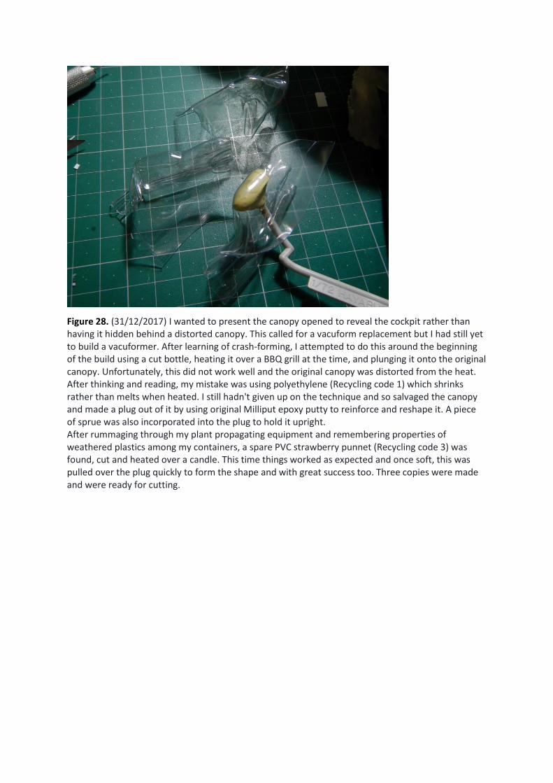
Figure 28. (31/12/2017) I wanted to present the canopy opened to reveal the cockpit rather than having it hidden behind a distorted canopy. This called for a vacuform replacement but I had still yet to build a vacuformer. After learning of crash-forming, I attempted to do this around the beginning of the build using a cut bottle, heating it over a BBQ grill at the time, and plunging it onto the original canopy. Unfortunately, this did not work well and the original canopy was distorted from the heat. After thinking and reading, my mistake was using polyethylene (Recycling code 1) which shrinks rather than melts when heated. I still hadn't given up on the technique and so salvaged the canopy and made a plug out of it by using original Milliput epoxy putty to reinforce and reshape it. A piece of sprue was also incorporated into the plug to hold it upright. After rummaging through my plant propagating equipment and remembering properties of weathered plastics among my containers, a spare PVC strawberry punnet (Recycling code 3) was found, cut and heated over a candle. This time things worked as expected and once soft, this was pulled over the plug quickly to form the shape and with great success too. Three copies were made and were ready for cutting.
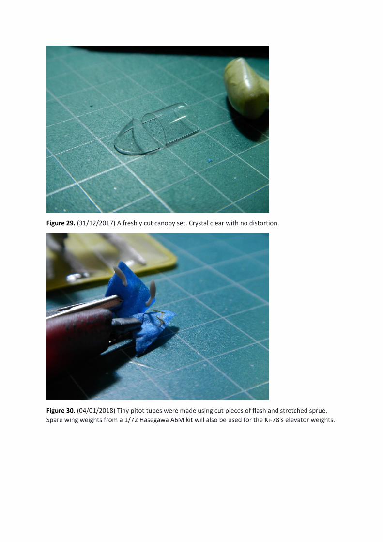
Figure 29. (31/12/2017) A freshly cut canopy set. Crystal clear with no distortion.
Figure 30. (04/01/2018) Tiny pitot tubes were made using cut pieces of flash and stretched sprue.
Spare wing weights from a 1/72 Hasegawa A6M kit will also be used for the Ki-78's elevator weights.
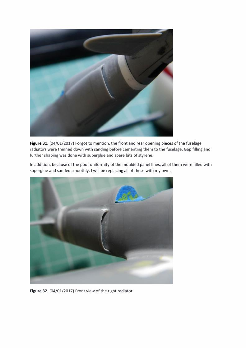
Figure 31. (04/01/2017) Forgot to mention, the front and rear opening pieces of the fuselage
radiators were thinned down with sanding before cementing them to the fuselage. Gap filling and
further shaping was done with superglue and spare bits of styrene.
In addition, because of the poor uniformity of the moulded panel lines, all of them were filled with
superglue and sanded smoothly. I will be replacing all of these with my own.
Figure 32. (04/01/2017) Front view of the right radiator.
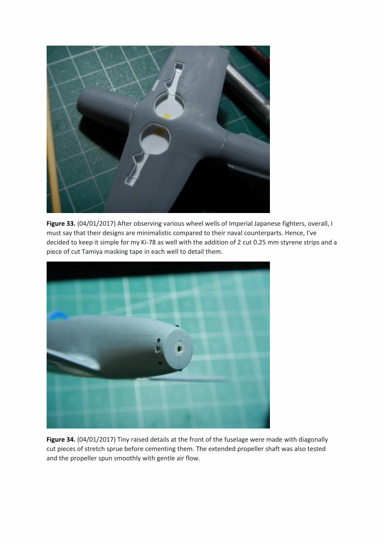
Figure 33. (04/01/2017) After observing various wheel wells of Imperial Japanese fighters, overall, I
must say that their designs are minimalistic compared to their naval counterparts. Hence, I've
decided to keep it simple for my Ki-78 as well with the addition of 2 cut 0.25 mm styrene strips and a
piece of cut Tamiya masking tape in each well to detail them.
Figure 34. (04/01/2017) Tiny raised details at the front of the fuselage were made with diagonally
cut pieces of stretch sprue before cementing them. The extended propeller shaft was also tested
and the propeller spun smoothly with gentle air flow.
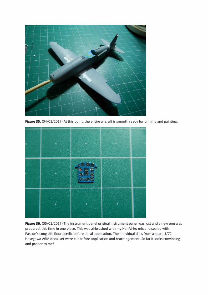
Figure 35. (04/01/2017) At this point, the entire aircraft is smooth ready for priming and painting.
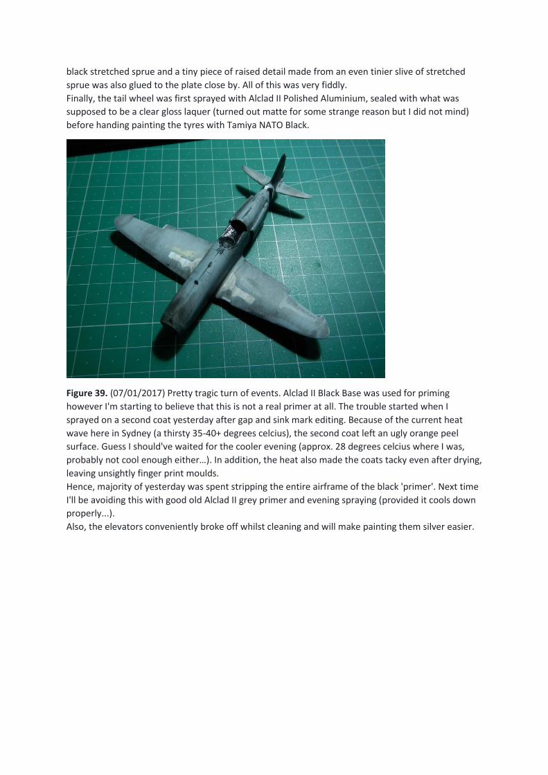
Figure 36. (05/01/2017) The instrument panel original instrument panel was lost and a new one was
prepared, this time in one piece. This was airbrushed with my Hai-Ai-Iro mix and sealed with
Pascoe's Long Life floor acrylic before decal application. The individual dials from a spare 1/72
Hasegawa A6M decal set were cut before application and rearrangement. So far it looks convincing
and proper to me!
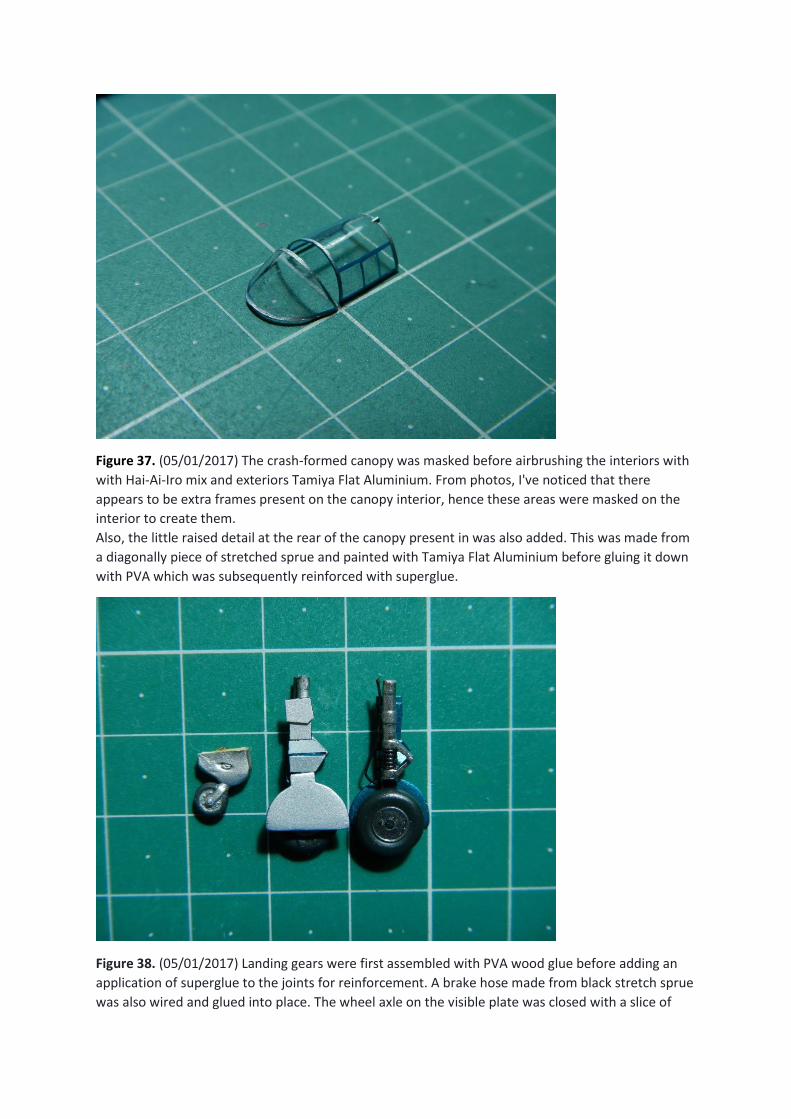
Figure 37. (05/01/2017) The crash-formed canopy was masked before airbrushing the interiors with
with Hai-Ai-Iro mix and exteriors Tamiya Flat Aluminium. From photos, I've noticed that there
appears to be extra frames present on the canopy interior, hence these areas were masked on the
interior to create them.
Also, the little raised detail at the rear of the canopy present in was also added. This was made from
a diagonally piece of stretched sprue and painted with Tamiya Flat Aluminium before gluing it down
with PVA which was subsequently reinforced with superglue.
Figure 38. (05/01/2017) Landing gears were first assembled with PVA wood glue before adding an
application of superglue to the joints for reinforcement. A brake hose made from black stretch sprue
was also wired and glued into place. The wheel axle on the visible plate was closed with a slice of
black stretched sprue and a tiny piece of raised detail made from an even tinier slive of stretched
sprue was also glued to the plate close by. All of this was very fiddly.
Finally, the tail wheel was first sprayed with Alclad II Polished Aluminium, sealed with what was
supposed to be a clear gloss laquer (turned out matte for some strange reason but I did not mind)
before handing painting the tyres with Tamiya NATO Black.
Figure 39. (07/01/2017) Pretty tragic turn of events. Alclad II Black Base was used for priming
however I'm starting to believe that this is not a real primer at all. The trouble started when I
sprayed on a second coat yesterday after gap and sink mark editing. Because of the current heat
wave here in Sydney (a thirsty 35-40+ degrees celcius), the second coat left an ugly orange peel
surface. Guess I should've waited for the cooler evening (approx. 28 degrees celcius where I was,
probably not cool enough either…). In addition, the heat also made the coats tacky even after drying,
leaving unsightly finger print moulds.
Hence, majority of yesterday was spent stripping the entire airframe of the black 'primer'. Next time
I'll be avoiding this with good old Alclad II grey primer and evening spraying (provided it cools down
properly...).
Also, the elevators conveniently broke off whilst cleaning and will make painting them silver easier.
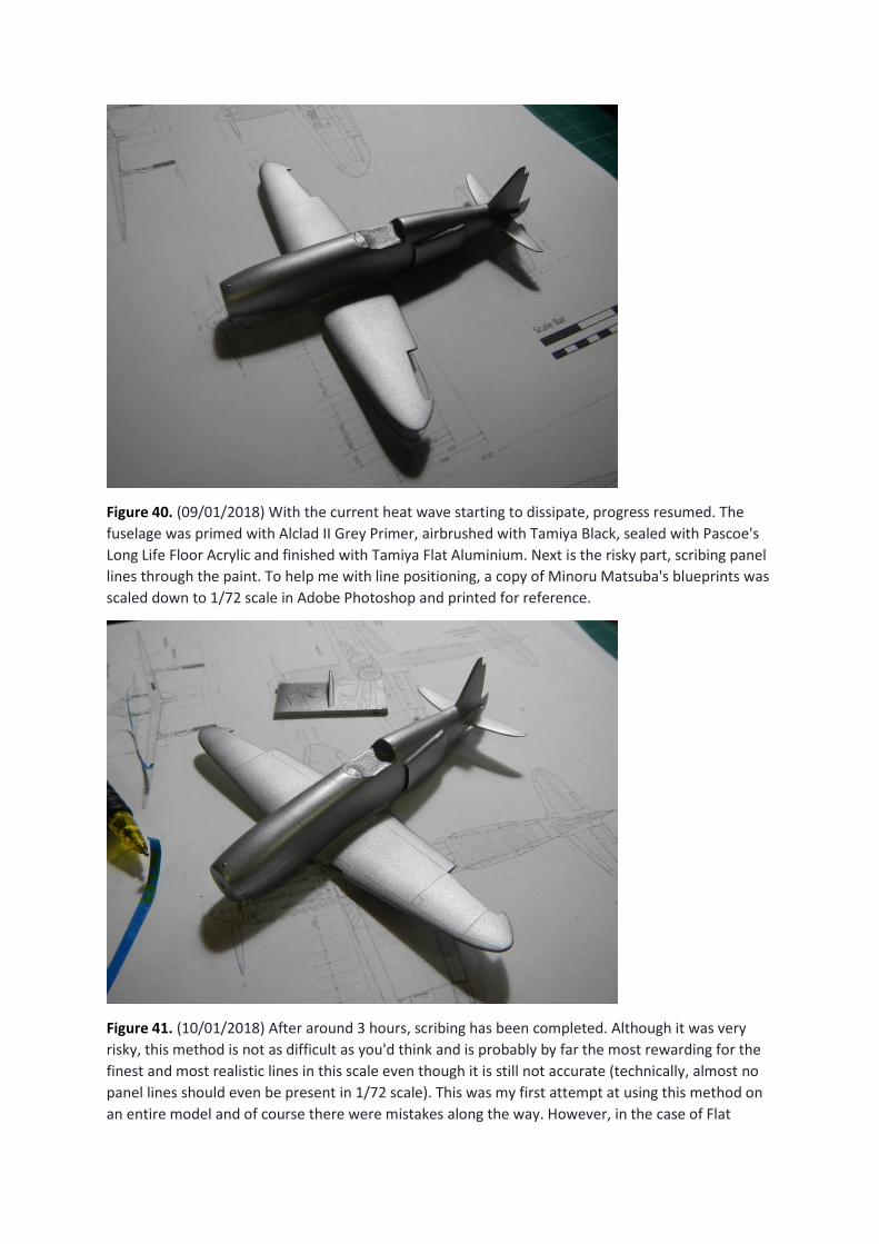
Figure 40. (09/01/2018) With the current heat wave starting to dissipate, progress resumed. The
fuselage was primed with Alclad II Grey Primer, airbrushed with Tamiya Black, sealed with Pascoe's
Long Life Floor Acrylic and finished with Tamiya Flat Aluminium. Next is the risky part, scribing panel
lines through the paint. To help me with line positioning, a copy of Minoru Matsuba's blueprints was
scaled down to 1/72 scale in Adobe Photoshop and printed for reference.
Figure 41. (10/01/2018) After around 3 hours, scribing has been completed. Although it was very
risky, this method is not as difficult as you'd think and is probably by far the most rewarding for the
finest and most realistic lines in this scale even though it is still not accurate (technically, almost no
panel lines should even be present in 1/72 scale). This was my first attempt at using this method on
an entire model and of course there were mistakes along the way. However, in the case of Flat
Aluminium, I have found that faulty lines can be covered up easily with delicate airbrushing,
achieving a minimally noticeable result which is good enough for me.
Next is painting the final details.
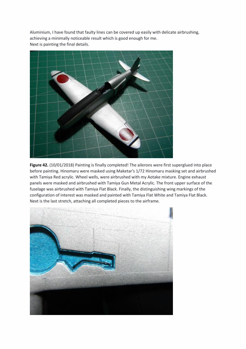
Figure 42. (10/01/2018) Painting is finally completed! The ailerons were first superglued into place
before painting. Hinomaru were masked using Maketar's 1/72 Hinomaru masking set and airbrushed
with Tamiya Red acrylic. Wheel wells, were airbrushed with my Aotake mixture. Engine exhaust
panels were masked and airbrushed with Tamiya Gun Metal Acrylic. The front upper surface of the
fuselage was airbrushed with Tamiya Flat Black. Finally, the distinguishing wing markings of the
configuration of interest was masked and painted with Tamiya Flat White and Tamiya Flat Black.
Next is the last stretch, attaching all completed pieces to the airframe.
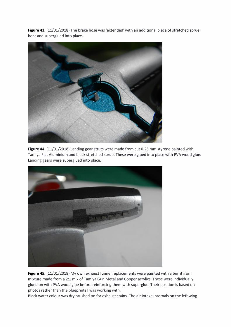
Figure 43. (11/01/2018) The brake hose was 'extended' with an additional piece of stretched sprue,
bent and superglued into place.
Figure 44. (11/01/2018) Landing gear struts were made from cut 0.25 mm styrene painted with
Tamiya Flat Aluminium and black stretched sprue. These were glued into place with PVA wood glue.
Landing gears were superglued into place.
Figure 45. (11/01/2018) My own exhaust funnel replacements were painted with a burnt iron
mixture made from a 2:1 mix of Tamiya Gun Metal and Copper acrylics. These were individually
glued on with PVA wood glue before reinforcing them with superglue. Their position is based on
photos rather than the blueprints I was working with.
Black water colour was dry brushed on for exhaust stains. The air intake internals on the left wing
were also filled with black water colour to enhance the illusion of depth. Also, the flat black surface
of the upper surface was sanded lightly at the edges and resprayed after noticing a slight error in its
positioning.
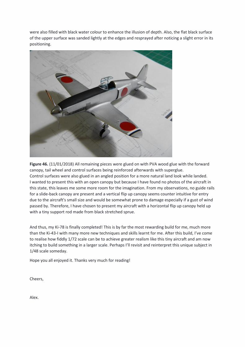
Figure 46. (11/01/2018) All remaining pieces were glued on with PVA wood glue with the forward
canopy, tail wheel and control surfaces being reinforced afterwards with superglue.
Control surfaces were also glued in an angled position for a more natural land look while landed.
I wanted to present this with an open canopy but because I have found no photos of the aircraft in
this state, this leaves me some more room for the imagination. From my observations, no guide rails
for a slide-back canopy are present and a vertical flip up canopy seems counter intuitive for entry
due to the aircraft's small size and would be somewhat prone to damage especially if a gust of wind
passed by. Therefore, I have chosen to present my aircraft with a horizontal flip up canopy held up
with a tiny support rod made from black stretched sprue.
And thus, my Ki-78 is finally completed! This is by far the most rewarding build for me, much more
than the Ki-43-I with many more new techniques and skills learnt for me. After this build, I’ve come
to realise how fiddly 1/72 scale can be to achieve greater realism like this tiny aircraft and am now
itching to build something in a larger scale. Perhaps I’ll revisit and reinterpret this unique subject in
1/48 scale someday.
Hope you all enjoyed it. Thanks very much for reading!
Cheers,
Alex.