Embed Size (px)
Citation preview

756
7 CFR Ch. XVII (1–1–12 Edition) § 1755.910
wrap is optional for reels weighing 75 lbs or less.
(3) The thermal wrap must meet the requirements included in the Thermal Reel Wrap Test, described below in para-graphs (w)(3)(i) and (w)(3)(ii) of this section. This test procedure is for qual-ification of initial and subsequent changes in thermal reel wraps.
(i) Sample selection. All testing must be performed on two 450 millimeter (18 inches) lengths of cable removed se-quentially from the same fiber jack-eted cable. This cable must not have been exposed to temperatures in excess of 38 °C (100 °F) since its initial cool down after sheathing.
(ii) Test procedure. (A) Place the two samples on an insulating material such as wood.
(B) Tape thermocouples to the jack-ets of each sample to measure the jack-et temperature.
(C) Cover one sample with the ther-mal reel wrap.
(D) Expose the samples to a radiant heat source capable of heating the un-covered sample to a minimum of 71 °C (160 °F). A GE 600 watt photoflood lamp or an equivalent lamp having the light spectrum approximately that of the sun must be used.
(E) The height of the lamp above the jacket must be 380 millimeters (15 inches) or an equivalent height that produces the 71 °C (160 °F) jacket tem-perature on the unwrapped sample must be used.
(F) After the samples have stabilized at the temperature, the jacket tem-peratures of the samples must be re-corded after one hour of exposure to the heat source.
(G) Compute the temperature dif-ference between jackets.
(H) The temperature difference be-tween the jacket with the thermal reel wrap and the jacket without the reel wrap must be greater than or equal to 17 °C (63 °F).
(4) Cable must be sealed at the ends to prevent entrance of moisture.
(5) The end-of-pull (outer end) of the cable must be securely fastened to pre-vent the cable from coming loose dur-ing transit. The start-of-pull (inner end) of the cable must project through a slot in the flange of the reel, around an inner riser, or into a recess on the
flange near the drum and fastened in such a way to prevent the cable from becoming loose during installation.
(6) Spikes, staples or other fastening devices must be used in a manner which will not result in penetration of the cable.
(7) The minimum size arbor hole must be 44.5 mm (1.75 inch) and must admit a spindle without binding.
(8) Each reel must be plainly marked to indicate the direction in which it should be rolled to prevent loosening of the cable on the reel.
(9) Each reel must be stenciled or let-tered with the name of the manufac-turer.
(10) The following information must be either stenciled on the reel or on a tag firmly attached to the reel: Optical Cable, Type and Number of Fibers, Ar-mored or Nonarmored, Year of Manu-facture, Name of Cable Manufacturer, Length of Cable, Reel Number, REA 7 CFR 1755.903.
Example: Optical Cable, G.657 class A, 4 fibers, Armored. XYZ Company, 1050 meters, Reel Number 3, REA 7 CFR 1755.903.
(11) When pre-connectorized cable is shipped, the splicing modules must be protected to prevent damage during shipment and handling.
[74 FR 20561, May 5, 2009]
§ 1755.910 RUS specification for out-side plant housings and serving area interface systems.
(a) Scope. (1) The purpose of this spec-ification is to inform manufacturers and users of outside plant housings and serving area interface (SAI) systems of the engineering and technical require-ments that are considered necessary for satisfactory performance in outside plant environments. Included are the mechanical, electrical, and environ-mental requirements, desired design features, and test methods for evalua-tion of the product.
(2) The housing and terminal require-ments reflect the best engineering judgment available at the present time and may be subject to change due to advances in technology, economic con-ditions, or other factors.
(3) The test procedures described in this section are required by RUS to demonstrate the functional reliability

757
Rural Utilities Service, USDA § 1755.910
of the product. However, other stand-ard or unique test procedures may serve the same function. In such cases, RUS shall evaluate the test procedures and results on an individual basis.
(4) The test procedures specified herein satisfy the requirements of housings as well as the requirements of terminals that may be installed within housings. Some of the requirements are interrelated to several tests designed to determine the performance aspects of terminals and are directly affected by testing required for housings. Therefore, the manufacturer should carefully review all the test require-ments in order to develop a testing schedule that is comprehensive, effi-cient in terms of the number of test specimens required and can be accom-plished in an orderly and logical se-quence.
(5) The specified tests may require special facilities to comply with Fed-eral, State, or local regulatory require-ments. Some test procedures are poten-tially hazardous to personnel because of the high voltages and mechanical forces involved. Safety precautions are necessary to prevent injury.
(6) Underwriters Laboratories, Inc. (UL) 94, Tests for Flammability of Plastic Materials for Parts in Devices and Appliances, fourth edition, dated June 18, 1991, referenced in this section is incorporated by reference by RUS. This incorporation by reference was ap-proved by the Director of the Federal Register in accordance with 5 U.S.C. 552(a) and 1 CFR part 51. A copy of the UL standard is available for inspection during normal business hours at RUS, room 2845–S, U.S. Department of Agri-culture, Washington, DC 20250–1500, or at the National Archives and Records Administration (NARA). For informa-tion on the availability of this mate-rial at NARA, call 202–741–6030, or go to: http://www.archives.gov/ federallregister/ codeloflfederallregulations/ ibrllocations.html. Copies are available from UL Inc., 333 Pfingsten Road, Northbrook, Illinois 60062–2096, tele-phone number (708) 272–8800.
(7) The American Society for Testing and Materials Specifications (ASTM) A 109–91, Standard Specification for Steel, Strip, Carbon, Cold-Rolled;
ASTM A 153–82 (Reapproved 1987), Standard Specification for Zinc Coat-ing (Hot-Dip) on Iron and Steel Hard-ware; ASTM A 366/A 366M–91, Standard Specification for Steel, Sheet, Carbon, Cold-Rolled, Commercial Quality; ASTM A 525–91b, Standard Specifica-tion for General Requirements for Steel Sheet, Zinc-Coated (Galvanized) by the Hot-Dip Process; ASTM A 526/A 526M–90, Standard Specification for Steel Sheet, Zinc-Coated (Galvanized) by the Hot-Dip Process, Commercial Quality; ASTM A 569/A 569M–91a, Standard Specification for Steel, Car-bon (0.15 Maximum, Percent), Hot- Rolled Sheet and Strip Commercial Quality; ASTM A 621/A 621M–92, Stand-ard Specification for Steel, Sheet and Strip, Carbon, Hot-Rolled, Drawing Quality; ASTM B 117–90, Standard Test Method of Salt Spray (Fog) Testing; ASTM B 539–90, Standard Test Methods for Measuring Contact Resistance of Electrical Connections (Static Con-tacts); ASTM B 633–85, Standard Speci-fication for Electrodeposited Coatings of Zinc on Iron and Steel; ASTM D 523– 89, Standard Test Method for Specular Gloss; ASTM D 610–85 (Reapproved 1989), Standard Test Method for Evalu-ating Degree of Rusting on Painted Steel Surfaces; ASTM D 822–89, Stand-ard Practice for Conducting Tests on Paint and Related Coatings and Mate-rials using Filtered Open-Flame Car-bon-Arc Light and Water Exposure Ap-paratus; ASTM D 1535–89, Standard Test Method for Specifying Color by the Munsell System; ASTM D 1654–92, Standard Test Method for Evaluation of Painted or Coated Specimens Sub-jected to Corrosive Environments; ASTM D 1693–70 (Reapproved 1988), Standard Test Method for Environ-mental Stress-Cracking of Ethylene Plastics; ASTM D 2197–86 (Reapproved 1991), Standard Test Method for Adhe-sion of Organic Coatings by Scrape Ad-hesion; ASTM D 2247–92, Standard Practice for Testing Water Resistance of Coatings in 100% Relative Humidity; ASTM D 2565–92, Standard Practice for Operating Xenon Arc-Type Light-Expo-sure Apparatus With and Without Water for Exposure of Plastics; ASTM D 2794–92, Standard Test Method for Resistance of Organic Coatings to the Effects of Rapid Deformation (Impact);

758
7 CFR Ch. XVII (1–1–12 Edition) § 1755.910
ASTM D 3928–89, Standard Test Method for Evaluation of Gloss or Sheen Uni-formity; ASTM D 4568–86, Standard Test Methods for Evaluating Compat-ibility Between Cable Filling and Flooding Compounds and Polyolefin Cable Materials; ASTM G 21–90, Stand-ard Practice for Determining Resist-ance of Synthetic Polymeric Materials to Fungi; and ASTM G 23–90, Standard Practice for Operating Light-Exposure Apparatus (Carbon-Arc Type) With and Without Water for Exposure of Non-metallic Materials, referenced in this section are incorporated by reference by RUS. These incorporations by ref-erences were approved by the Director of the Federal Register in accordance with 5 U.S.C. 552(a) and 7 CFR part 51. Copies of the ASTM standards are available for inspection during normal business hours at RUS, room 2845–S, U.S. Department of Agriculture, Wash-ington, DC 20250–1500, or at the Na-tional Archives and Records Adminis-tration (NARA). For information on the availability of this material at NARA, call 202–741–6030, or go to: http:// www.archives.gov/federallregister/ codeloflfederallregulations/ ibrllocations.html. Copies are available from ASTM, 1916 Race Street, Philadel-phia, Pennsylvania 19103–1187, tele-phone number (215) 299–5585.
(b) General information. (1) Outside plant housings are fabricated of either metallic or nonmetallic materials in different sizes and configurations to suit a variety of applications. The pur-pose of a housing is to protect its con-tents from environmental elements, ro-dents, insects, or vandalism and unau-thorized access. Housings are designed with internal brackets for accommo-dating splicing, bonding and grounding connections, cable terminals, cross- connect facilities, load coils, and opti-cal and electronic equipment.
(2) Pedestals are housings primarily intended to house, organize, and pro-tect cable terminations incorporating terminal blocks, splice connectors and modules, ground lugs and load coils. Activities typically performed in a ped-estal are cable splicing, shield bonding and grounding, inductive loading, and connection of subscriber drops.
(3) Serving area interface (SAI) cabi-nets are housings intended to perform
some of the same functions as ped-estals but are primarily intended to serve as the connecting terminal be-tween feeder cable and distribution ca-bles.
(4) Outside plant housings shall be manufactured in accordance with Na-tional Electrical Code (NEC) require-ments, Underwriters’ Laboratories (UL) requirements, Department of Labor, Occupational Safety and Health Administration Standards (OSHA), and all other applicable Federal, State, and local requirements including, but not limited to, statutes, rules, regulations, orders, or ordinances otherwise im-posed by law.
(c) General documentation require-ments—(1) Installation and maintenance instructions. (i) Each product shall have available a set of instructions designed to provide sufficient information for the successful installation of the hous-ing, cables, auxiliary equipment, and the associated splice preparation. The instructions shall be of sufficient size to be easily read and shall be printed using waterproof ink. Pedestal instruc-tion sheets shall include a list of mis-cellaneous replacement parts that may be purchased locally. SAI systems shall be supplied with complete instructions for installation and use.
(ii) When requested by RUS, or an RUS borrower, the manufacturer shall prepare a training package for the pur-pose of training technicians in the use and installation of the product and its auxiliary equipment.
(iii) The manufacturer shall provide ordering information for repair parts. Repair parts shall be obtainable through a local distributor or shall be easily obtainable. Information describ-ing equivalent parts and their sources should be provided for those parts that may also be obtained from other sources.
(2) Quality assurance. The manufac-turer shall demonstrate the existence of an ongoing quality assurance pro-gram that includes controls, proce-dures, and standards used for vendor certification, source inspection, incom-ing inspection, manufacture, in process testing, calibration and maintenance of tools and test equipment, final product

759
Rural Utilities Service, USDA § 1755.910
inspection and testing, periodic quali-fication testing and control of noncon-forming materials and products. The manufacturer shall maintain quality assurance records for five years.
(3) RUS acceptance applications. (i) The tests described in this specifica-tion are required for acceptance of product designs and major modifica-tions of accepted designs. All modifica-tions shall be considered major unless otherwise declared by RUS. The tests are intended to show the inherent ca-pability of the manufacturer to produce products which have an ex-pected service life of 30 years.
(ii) For initial acceptance the manu-facturer shall:
(A) Submit an original signature cer-tification that the product complies with each section of the specification;
(B) Provide qualification test data; (C) Provide OSHA Material Safety
Data Sheets for the product; (D) Provide a detailed explanation
concerning the intended use and capac-ity of the product;
(E) Provide a complete set of instruc-tions, recommendations for equipment organization and splicing;
(F) Agree to periodic plant inspec-tions;
(G) Provide a certification that the product does or does not comply with the domestic origin manufacturing pro-visions of the ‘‘Buy American’’ require-ments of the Rural Electrification Act of 1938 (52 Stat. 818);
(H) Provide user testimonials con-cerning field performance of the prod-uct;
(I) Provide product samples if re-quested by RUS; and
(J) Provide any other data required by the Chief, Outside Plant Branch (Telephone).
(iii) Each requirement of this section must be addressed in submissions for acceptance. The designation N/A may be entered when the requirements do not apply.
(iv) Acceptance requests should be addressed to: Chairman, Technical Standards, Committee ‘‘A’’ (Tele-phone), Telecommunications Standards Division, Rural Utilities Service, Washington, DC 20250–1500.
(d) Functional design criteria for housings—(1) General requirements. (i)
The functional requirements for housings concern materials, finishes, environmental factors, and design fea-tures that are applicable to most above ground housings used in the outside plant.
(ii) Housings shall be of sufficient size to permit easily managed installa-tion, operational, testing, and mainte-nance operations. The general shape of outside plant housings is usually com-parable to that of a rectangular col-umn or cylinder, with the shape of any particular housing being left to the manufacturer’s discretion. Each design is subject to acceptance by RUS.
(2) Housing types and capacities. (i) Housings used in outside plant are ei-ther the smaller housings generally known as pedestals or larger housings known as equipment or splice cabinets. Both categories may have designs in-tended for stake mounting, pole mounting, or pad mounting.
(ii) The classifications of pedestals are the general purpose channel Type (H) and the dome Type (M). The Type H pedestal has either front only access or back and front access while the Type M pedestal has top only access. Pedestals are further designated as follows:
Stake mount-ed Type Pole mount-
ed
Pole mount-ed (extra
high)
BD3 H BD3A BD4 H BD4A BD5 H BD5A BD7 H BD7A BD14 M BD14A BD14AG BD15 M BD15A BD15AG BD16 M BD16A BD16AG
(iii) The minimum volume associated with the pedestal designations shall be as shown in the following table:
Pedestal 1 housing designation
Minimum volume
Cubic centi-
meters cm 3
(Cubic Inches)
(in.3)
BD3, BD3A 2 ....................................... 9,000 (550) BD4, BD4A 2 ....................................... 15,000 (900) BD5, BD5A 2 ....................................... 35,000 (2,100) BD7( 2 ) ................................................. 72,000 (4,400) BD14, BD14A, BD14AG 3 ................... 9,000 (550) BD15, BD15A, BD15AG 3 ................... 27,000 (1,600) BD16, BD16A, BD16AG 3 ................... 38,000 (2,300)
NOTE 1: Housings designed for unique purposes will be evaluated on a case-by-case basis.
NOTE 2: For Type H pedestals, the minimum volume is that space as measured 5 centimeters (cm) (2 inches (in.)) below the top of the housing to a point 40 cm (16 in.) above the bot-tom of the lower cover plate.

760
7 CFR Ch. XVII (1–1–12 Edition) § 1755.910
NOTE 3: The minimum volume of the Type M pedestals shall be the space within the dome measured from the lower edge of the dome to a point 5 cm (2 in.) from the top.
(iv) Equipment cabinets intended for use as SAI housings shall be assigned size designations according to their maximum pair termination capacities. The capacity will vary depending on the type of terminating equipment used. SAI cabinets shall be suffix des-ignated with an ‘‘A’’ for pole mounting, ‘‘X’’ for pad mounting, and ‘‘S’’ for stake mounting.
(v) Large pair count splice cabinets are classified according to their splice capacity. Approximately 48 cm3 (3.0 in.3) of splice area per pair straight spliced shall be permitted.
(vi) The minimum volume associated with large pair count splice cabinets shall be as shown in the following table:
Splice cabinet 1 designa-tion
Minimum volume Max-imum splice
capacity (pairs)
(cm.3) (in.3)
BD6000 295,000 (18,000) 6,000 BD8000 393,000 (24,000) 8,000 BD10000 491,000 (30,000) 10,000
NOTE 1: Additional sizes of splice cabinets shall be consid-ered by RUS on a case-by-case basis.
(3) Design and fabrication requirements for housings. (i) Type H pedestal housings may consist of an enclosed channel incorporating an integrally mounted stake that serves as a backplate, or they may be designed for universal mounting on stakes or poles. The body of the housing shall have two major components; an upper cover and a base cover. The upper cover shall have a top, front and back plate with the front cover removable to permit entry and provide increased work space. The base cover shall consist of a front plate and back plate. The base cover back plate may be an extension of the upper back plate cover.
(ii) Type M pedestal housings shall consist of a one piece upper sleeve de-signed to fit over the base cover trap-ping air to prohibit water from enter-ing the splice area when installed in lo-cations prone to temporary flooding. Pedestals designed to be mounted extra high on poles for locations susceptible to deep snow shall have a bottom close- off option available to prohibit the in-gress of birds, rodents and insects.
(iii) The external housing compo-nents on all outside plant housings shall provide reasonable protection against accidental removal or van-dalism. Housings shall be equipped with a cover plate retaining bolt and cup washer that may be opened only with an industry accepted socket type can wrench. Housings may be equipped with provisions to allow the purchaser to install a padlock.
(iv) Installed housings shall resist the disassembling force of frost heav-ing applied to the bottom of ground line cover plates. The base cover must remain stationary to stabilize the con-tents of the housing cavity.
(v) In an effort to provide protection against dust penetration, blowing snow, rain, and ultraviolet light deg-radation of internal components, all mechanical gaps shall be restricted. The use of seals, overlaps, gaskets, and/ or dovetailing is required to assure sat-isfactory protection of housed equip-ment.
(vi) Knockouts, cutouts, or notches designed to accommodate aerial serv-ice drops shall not be permitted. A de-sign option for housings intended to ac-commodate service drops shall include a separate channel or equivalent in the base cover to allow future additions of service drops without the removal of gravel or the moisture barrier in the base of the housing. Service wire chan-nels must be designed to prevent the entry of birds, reptiles, rodents and in-sects.
(vii) Minimal venting of SAI housings may be necessary to relieve internal pressure and condensation.
(viii) There shall be no aluminum housing components that will become buried in the soil when the housing is properly installed.
(ix) Housing components may be as-sembled using rivets, welds, glue, bolts and nuts, or other techniques suitable for the materials involved.
(x) Housings and their components that require field assembly must be ca-pable of being assembled with tools normally available to outside plant technicians.
(xi) Hinged doors on SAI housings and large pair count splice housings shall be equipped with a device that re-strains the doors in the open position.

761
Rural Utilities Service, USDA § 1755.910
(xii) Outside plant housings shall be free of sharp edges, burrs, etc., that could present a safety hazard to per-sonnel involved in installation and use of the product or to the general public. Surfaces inside housings must not allow pinching of conductors during in-stallation of cover plates or the open-ing and closing of doors.
(xiii) A ground line mark shall be provided, approximately 15 cm (6 in.) below the top edge of the housing base cover plate on housings intended for ground level mounting. Base cover plates shall have a minimum height of 31 cm (12 in.).
(xiv) Any housing, which weighs in excess of 91 kilograms (kg) (200 pounds (lb)), including its contents, shall be equipped with lifting brackets for at-taching hoisting cables or chains.
(xv) Housing stakes shall be a min-imum of 107 cm (42 in.) in length. If fab-ricated from steel, they shall have a minimum thickness of No. 13 gauge as measured according to American Soci-ety for Testing and Materials (ASTM) A 525–91b. Stakes shall be formed into a ‘‘U’’ channel with a minimum depth of 2 cm (0.75 in.). The stake shall be a single part of suitable design strength for driving 91 cm (36 in.) into the soil with hand tools without damage such as bending or warping. The stake shall have adequate mounting holes having a minimum separation of 15 cm (6 in.) for mounting the housing baseplate. The stake material must resist corrosion and deterioration when exposed to soil and atmospheric conditions.
(xvi) The housing design must permit a logical progression of installation steps that would normally be encoun-tered in typical field installations.
(xvii) Provisions for attaching housings to stakes, poles, walls, other housings, or pads shall be provided for each design intended for those pur-poses. Locations of holes for mounting attachments may be provided by knockouts on above ground compo-nents. Mounting hole locations for below ground components may be predrilled.
(xviii) Pole mounting hardware shall provide at least 1.3 cm (0.5 in.) clear-ance from the pole to the housing. Pole mounting brackets shall accommodate
the wide range of pole sizes used in the telephone industry.
(xix) Pad-mounted housings shall have hardware available for anchoring the housing base to the pad. A tem-plate may be provided to assist in the location of mounting attachment de-tails for pad preparation.
(xx) Housings equipped with stub ca-bles shall have strain relief devices to permit shipping and handling of the housing without damage to the housing or stub cables. Only RUS accepted cable shall be used for stub cables. The cable manufacturer’s recommendations concerning minimum bend radius shall be observed. The minimum bend radius for most copper cables is 10 times the cable diameter.
(xxi) Cable supports shall be provided near the top of the ground line cover and other appropriate locations within the housing to provide cable stability consistent with the intended use and capacity of the housing. Cable supports shall be capable of holding a minimum load of 23 kg (50 lb).
(xxii) An adequate supply of non-metallic retainer clips or tie wraps ca-pable of supporting a minimum load of 23 kg (50 lb) shall be provided with the housing. Adequate spaces for installa-tion of the clips or tie wraps must be provided on the housing backplate and cable supports.
(xxiii) Housing chambers designed for splicing operations shall be equipped with insulated supporting straps or rods suitable for supporting splice bun-dles. The insulation on the straps or rods shall extend for the entire length of the device and shall have a dielectric strength of 15 kilovolts (kv) direct cur-rent (dc) minimum. Housings having an ‘‘H’’ frame design where both front and rear covers may be removed may incor-porate insulated tie bars to be used as cable supports.
(xxiv) Housings designed to contain equipment in addition to splices shall be equipped with a device for phys-ically separating the splice area from the service area of the housing.
(xxv) A dielectric shield rated at 15 kv dc shall be provided to enclose the cable splice area. The shield shall ex-tend from the lower cable supports to within 2.5 cm (1 in.) of the top of the housing. The shield shall be equipped

762
7 CFR Ch. XVII (1–1–12 Edition) § 1755.910
with Velcro or equivalent fastening de-vices designed to hold the shield in both the open or closed positions. The fastening devices shall extend along the entire vertical edge of the dielec-tric shield.
(xxvi) Mounting arrangements for a variety of terminal blocks and other equipment shall be provided by means of good housekeeping panels or other devices that may enhance the service aspect of the housing.
(xxvii) Housings designed for SAI cabinets may be shipped with terminal blocks installed and stub cables at-tached. If this option is exercised, the stub cables and terminal blocks must be RUS accepted. In all cases, SAI cabi-nets must be equipped with appropriate mounting devices for installing the pe-ripheral equipment required for a serv-ing area interface.
(xxviii) SAI cabinets shall be de-signed to provide physical separation between the splicing area and the area provided for running cross-connect jumpers.
(xxix) SAI cabinets and large splice housings must have an external feature for attaching a padlock to prevent un-authorized entry.
(xxx) Each housing shall have a tinned or zinc electroplated copper alloy or equivalent connector plate or bar to be used for terminating ground and cable shield bond connections. The device shall be equipped with captive studs and nuts with captive lock wash-ers designed for attaching 6 American Wire Gauge (AWG) copper bonding har-ness wire or braid and a 6 AWG copper ground wire. Connector plates shall be equipped with enough studs and nuts to provide individual connections equiva-lent to the maximum number of cable sheaths recommended for the housing. Housings shall incorporate design fea-tures that enable the field installation of at least one additional connector plate for service conditions that re-
quire numerous connections. A bonding and grounding system capable of pro-viding support and strain relief for service wires shall be provided for housings intended for use as distribu-tion points. The bonding system shall be designed to provide sheath con-tinuity as cable and service wires are installed, and prior to any other oper-ation being performed. The bonding ar-rangement shall provide electrical con-tinuity between all bonds and the ground connector plate. The bonding and grounding arrangement shall per-mit the lifting of individual cable ground connections for testing and cable locating activities without jeop-ardizing the grounding potential of other cables that may enter the hous-ing. The bonding and grounding system shall be capable of conducting a cur-rent of 1000 amperes for at least 20 sec-onds.
(4) Warning sign. (i) A buried cable warning sign shall be securely attached to the outside of each housing. The let-tering information on the sign shall be permanent.
(ii) For pedestals, the sign shall be centered horizontally on the front cover and the top of the sign shall be not more than 10 cm (4 in.) from the top of the housing.
(iii) For SAI cabinets, the sign shall be centered horizontally and vertically on the door. If there are two doors, the sign shall be mounted on the left door.
(iv) Deviations from warning sign lo-cation requirements are permitted only for housing design constraints. Alter-nate sign locations will be considered by RUS.
(v) The RUS standard sign design is shown in Figure 1.
(5) Housing materials. (i) Materials used in housings shall present no envi-ronmental or safety hazard as defined by industry standards or Federal, State, or local laws and regulations. Figure 1 is as follows:

763
Rural Utilities Service, USDA § 1755.910
(ii) All materials are required to have fire resistance ratings consistent with recognized industry standards. Exter-nal materials must be flame resistant.
(iii) All materials used in the manu-facture of housings or component parts must achieve the required strength properties, resist deterioration when exposed to outdoor conditions, and be

764
7 CFR Ch. XVII (1–1–12 Edition) § 1755.910
acceptable to RUS for the specific ap-plication. New materials or materials not familiar to the RUS staff shall be supported by test and performance data which demonstrates their suit-ability for the intended use.
(iv) Nonmetallic housing materials shall have a fungus growth rating no greater than one according to ASTM G 21–90.
(v) Metallic components shall be ei-ther corrosion resistant or protected against corrosion and must not produce galvanic corrosion in wet or humid conditions on other metals that may be present in the housing environ-ment.
(vi) Mill galvanized steel used in the manufacture of housings shall comply with the appropriate requirements of one of the following standards:
(A) ASTM A 109–91; (B) ASTM A 366/A 366M–91; (C) ASTM A 525–91b; or (D) ASTM A 526/A 526M–90. (vii) Hot rolled steel shall comply
with the appropriate requirements of one of the following standards:
(A) ASTM A 569/A 569M–91a; or (B) ASTM A 621/A 621M–92. (viii) Cold rolled steel shall comply
with the appropriate requirements of one of the following standards:
(A) ASTM A l09–91; or (B) ASTM A 366/A 366M–91. (ix) Steel parts used for internal
housing brackets shall be hexavalent chromate coated or zinc plated in ac-cordance with ASTM B 633–85.
(x) Hardware items used for assem-bling or fastening housing components shall be 300 series or passivated 400 se-ries stainless steel or hot dip galva-nized in accordance with ASTM A l53– 82 (1987). Other materials will be con-sidered by RUS on an individual basis.
(xi) Aluminum components shall be fabricated from alloy types 5052 or 6061 or other types that have been recog-nized as having acceptable corrosion resistance and formability and weldability features.
(xii) Nonmetallic parts must be re-sistant to solvents and stress cracking and shall be compatible with metals and other materials such as conductor insulations and filling compounds used in the manufacture of cable. Plastic materials must be noncorrosive to met-
als and resist deterioration when ex-posed to industrial chemical pollut-ants, ultra-violet rays, road salts, cleaning agents, insecticides, fer-tilizers, or other detrimental elements normally encountered in the outdoor environment.
(xiii) Housing door seals and gaskets may be manufactured from rubber or synthetic rubber-like elastomer mate-rials. Seals and gaskets shall exhibit a high degree of weatherability with an effective life of at least 30 years in the outdoor environment. The material shall be tear resistant and have a low compression set.
(6) Housing finish requirements. (i) All interior and exterior surfaces of housings shall be free from blisters, wrinkles, cracks, scratches, dents, heat marks, and other defects.
(ii) There shall be inherent design provisions to prevent objectionable de-terioration of the housing such as rust-ing, exposure of fiber or delamination. Secondary protection, such as gal-vanizing over steel per ASTM A 526/A 526M–90 or anodizing over aluminum, shall be provided to ensure reliability over the projected 30 year design life of the housing.
(iii) Painted metal housings shall have a minimum gloss of 60 (60 °specular) in accordance with ASTM D 523–89.
(iv) All painted surfaces shall have a uniform color and texture in accord-ance with ASTM D 3928–89. Non-metallic housings shall meet recog-nized industry standards concerning optical appearance for gloss and haze as applicable for the material.
(v) The colors of housings that RUS will consider for acceptance shall be as follows:
Color Standard
Gray-Green .......... Munsell 6.5 GY 6.03/1.6 Munsell 4.4 GY 6.74/1.5
Green ................... Munsell 8.8 G 2.65/5.3 Orange ................. Federal Standard 595A
Color Number l2246 Munsell 0.15YR 5.26/13.15
Chocolate ............. Munsell 5.27YR 2.40/2.60 Color Number 835
(7) Installation requirements. (i) The design of the housing must provide for a logical and normal installation se-quence, i.e., excavation, installation of

765
Rural Utilities Service, USDA § 1755.910
a foundation or base and anchoring de-vices, addition of hardware, installa-tion and bonding of cables, splicing, ad-dition of service, and final closing.
(ii) No special tools or equipment other than that usually carried by out-side plant technicians and construction crews must be required for installation of the housing. Security devices are the exception to this requirement.
(iii) Installation hardware shall maintain housings in an erect and sta-ble position when subjected to normal storm loads. Pad-mounted designs must accommodate precast or cast-in- place reinforced concrete or other suit-able prefabricated material. Brackets, inserts for fastening, conduit openings, or other items necessary for a pad- mounted installation must be provided. The manufacturer shall provide de-tailed drawings or a template for locat-ing inserts, conduit openings, or slots for cast-in-place pad construction.
(e) Performance criteria and test proce-dures for housings—(1) General informa-tion. (i) The housing manufacturer shall perform adequate inspections and tests to demonstrate that housings and housing components comply with RUS requirements.
(ii) Testing shall be performed at a room temperature of 24±3 °C (75±5 °C). Temperatures for testing performed at other than room temperature shall be determined as near the center of the product under test as practical.
(2) Description of test housing. (i) Each distinctly designed and configured fam-ily of housings intended to perform a particular function shall be tested.
(ii) The typical test sample shall con-sist of the exterior housing components such as covers, backplates, good house-keeping panels, cap assembly, anchor posts, decals, etc. Interior components must include the bonding and ground-ing hardware for cables and service wires and the dielectric shield. The housing may include terminal blocks or cross-connect modules, cable splices, or the typical outside plant equipment the housing is designed to contain and protect.
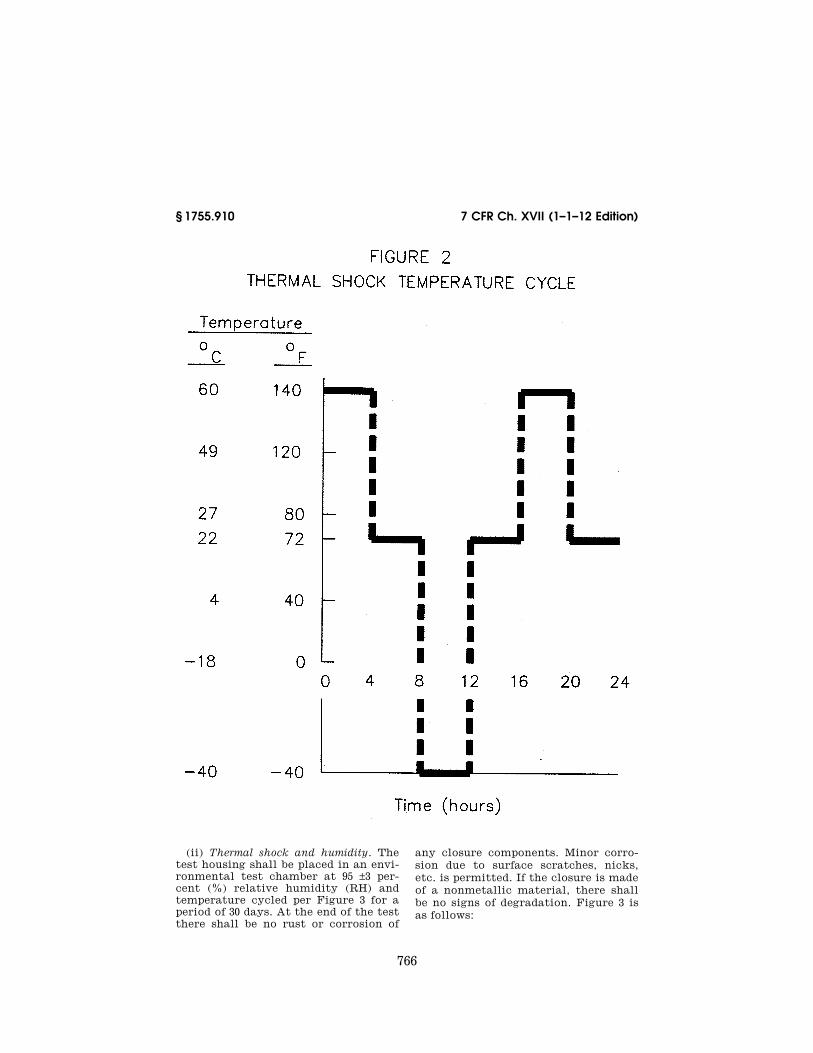
(3) Environmental requirement for housings—(i) Thermal shock. The test housing shall be placed in a test cham-ber and exposed to the temperature cycle of Figure 2 for five complete cy-cles. The step function nature of the temperature changes may be achieved by insertion and removal of the test housing from the chamber. The soak time at each temperature shall be four hours. The housing shall be removed from the test chamber at the conclu-sion of the five-cycle period. After the test housing temperature has stabilized to room temperature, the housing must be inspected for deterioration of mate-rials and satisfactory operation of me-chanical functions. Figure 2 is as fol-lows:
766
7 CFR Ch. XVII (1–1–12 Edition) § 1755.910
(ii) Thermal shock and humidity. The test housing shall be placed in an envi-ronmental test chamber at 95 ±3 per-cent (%) relative humidity (RH) and temperature cycled per Figure 3 for a period of 30 days. At the end of the test there shall be no rust or corrosion of
any closure components. Minor corro-sion due to surface scratches, nicks, etc. is permitted. If the closure is made of a nonmetallic material, there shall be no signs of degradation. Figure 3 is as follows:

767
Rural Utilities Service, USDA § 1755.910
(iii) Humidity and condensation. Test panels shall be placed in an environ-mental chamber and subjected to 1,008 hours (42 cycles) of exposure per ASTM D 2247–92. One cycle consists of 24 hours of 100% humidity (with condensation on the panels) at a cabinet temperature of 38±1 °C (100±2 °F) and an ambient temperature of 25±1 °C (77±2 °F) without heat input. Upon completion of cy-cling, the test panels shall be subjected to an 11 newton-meter (N-m) (100 pound-inches (lb-in.)) impact test using the Gardner-Impact Tester or equiva-lent. Test panels shall show no sub-strate or coating cracking or loss of coating adhesion on either side.
(iv) Weatherability. Three test panels shall be tested for weatherability in ac-cordance with the appropriate proce-dures of either ASTM D 822–89 or ASTM G 23–90. Total exposure time
shall be a minimum of 800 hours. Fail-ure is defined as fading, cracking, blis-tering, or delamination on any of the three test panels.
(v) Low temperature durability. Low temperature durability shall be proven by exposing the three test panels from (e)(3)(iv) of this section to at least 25 continuous cycles of the following test sequence:
(A) To insure complete saturation of the three test panels, soak them for 96 hours in a container of distilled water 22±2 °C (71.6±4 °F);
(B) Lower the temperature of the water and the immersed test panels to ¥28±2 °C (¥18.4±4 °F) and stabilize for 24 hours;
(C) Thaw the water with the samples to 22±2 °C (71.6±4 °F) and stabilize for 24 hours;
768
7 CFR Ch. XVII (1–1–12 Edition) § 1755.910
(D) Repeat the procedure 24 times. Any cracking, crazing, deforming, or delaminating on any of the three test panels shall be considered a failure; and
(E) Remove the samples from the water and impact test the three panels by delivering a force of 11.3 N-m (100 lb- in.) using a Gardner-Impact Tester to each specimen at 71, 22, and ¥28±2 °C (159.8, 71.6, and ¥18.4±4 °F), after stabi-lizing them at those temperatures for at least two hours. Visual inspection shall reveal no deformation or perfora-tions on any of the test panels.
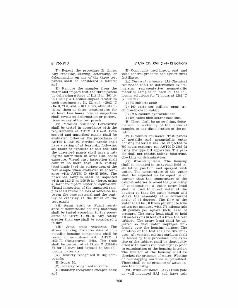
(vi) Corrosion resistance. Corrosivity shall be tested in accordance with the requirements of ASTM B 117–90. Both scribed and unscribed panels shall be evaluated following the procedures of ASTM D 1654–92. Scribed panels shall have a rating of at least six, following 500 hours of exposure to salt fog, and the unscribed panels shall have a rat-ing no lower than 10, after 1,000 hours exposure. Visual rust inspection shall confirm no more than 0.03% rusting (rust grade 9) of the surface area of the test sample when evaluated in accord-ance with ASTM D 610–85(1989). The unscribed samples shall be impacted with an 11.3 N-m (100 lb-in.) force, using a Gardner-Impact Tester or equivalent. Visual inspection of the impacted sam-ples shall reveal no loss of adhesion be-tween the base material and the coat-ing or cracking at the finish on the test panels.
(vii) Fungi resistance. Fungi resist-ance of nonmetallic housing materials shall be tested according to the proce-dures of ASTM G 21–90. Any rating greater than one shall be considered a failure.
(viii) Stress crack resistance. The stress cracking characteristics of non-metallic housing components shall be tested in accordance with ASTM D 1693–70 (Reapproved 1988). The tests shall be performed at 49±21⁄2 C (120±41⁄2 F) for 14 days and exposed to the fol-lowing materials:
(A) Industry recognized filling com-pounds;
(B) Isopar M; (C) Industry recognized solvents; (D) Industry recognized encapsulants;
and
(E) Commonly used insect, pest, and weed control products and agricultural fertilizers.
(ix) Chemical resistance. (A) Chemical resistance shall be determined by im-mersing representative nonmetallic material samples in each of the fol-lowing solutions for 72 hours at 22±2 °C (71.6±4 °F):
(1) 3% sulfuric acid; (2) 100 parts per million (ppm) tri-
chloroethane in water; (3) 0.2 N sodium hydroxide; and (4) Unleaded high octane gasoline. (B) There shall be no swelling, defor-
mation, or softening of the material samples or any discoloration of the so-lution.
(x) Ultraviolet resistance. Test panels of metallic and nonmetallic outer housing materials shall be subjected to 700 hours exposure per ASTM D 2565–92 using the type BH apparatus. The pan-els shall not exhibit fading, blistering, checking, or delamination.
(xi) Weathertightness. The housing shall be mounted in its typical field in-stallation position and sprayed with water. The temperature of the water shall be adjusted to be equal to or warmer than the temperature of the cabinet interior to avoid the possibility of condensation. A water spray head shall be used to direct water at the housing so that the water stream will strike the assembly at a downward angle of 45 degrees. The flow of the water shall be 3.8 liters per minute (one gallon per minute), with 276 kilopascals (40 pounds per square inch) head of pressure. The spray head shall be held 1.8 meters (m) (6 feet (ft)) from the test cabinet. The spray head shall be ad-justed so that water impinges uni-formly over the housing surface. The duration of the test shall be five min-utes. All vertical cabinet surfaces shall be tested by this procedure. The exte-rior of the cabinet shall be thoroughly dried with towels (no heat drying) prior to examination of the housing interior. The interior of the housing shall be checked for presence of water. Wetting of over-lapping surfaces is permitted. There shall be no presence of water in-side the housing.
(xii) Wind Resistance. (A)(1) Stub pole or wall mounted SAI and large pair

769
Rural Utilities Service, USDA § 1755.910
count splice housings shall be sub-jected to a load (F) as shown in Figure 4 and the following table to simulate the turning moment equivalent to a uniform wind load of 161 kilometers per hour (km/h) (100 miles per hour (mi/h)) perpendicular to the largest surface area.
Maximum area of largest surface square centimeters cm2 (Square inches) (in.2)
Load
kg (lb)
5,200 (800) or less ................................ 18 (40)
Maximum area of largest surface square centimeters cm2 (Square inches) (in.2)
Load
kg (lb)
5,201 to 9,100 (801 to 1,400) ............... 32 (70) 9,101 to 13,000 (1,401 to 2,000) .......... 45 (100) 13,001 to 16,200 (2,001 to 2,500) ........ 57 (125)
NOTE: The procedures for housings with larger surface area will be evaluated by RUS on a case-by-case basis.
(2) The housing shall remain in its original mounting position throughout the test and exhibit no mechanical de-formation.
(3) Figure 4 is as follows:

770
7 CFR Ch. XVII (1–1–12 Edition) § 1755.910
(B)(1) Pad or ground mounted SAI or splice housings shall be subjected to a load (F) as shown in Figure 5 and the following table to simulate the over-
turning moment equivalent to a uni-form wind load of 161 km/h (100 mi/h) perpendicular to the largest surface area.

771
Rural Utilities Service, USDA § 1755.910
Height cm (in.) Maximum area of largest surface cm2 (in.2) Load
kg (lb)
122 (48) or less ............................ 11,000 (1,700) or less ........................................................................ 91 (200) 11,001–13,000 (1,701–2,000) ............................................................ 104 (230) 13,001–14,900 (2,001–2,300) ............................................................ 118 (260)
123–152 (49–60) .......................... 11,700 (1,800) or less ........................................................................ 91 (200) 11,701–14,300 (1,801–2,200) ............................................................ 109 (240) 14,301–16,200 (2,201–2,500) ............................................................ 127 (280) 16,201–18,800 (2,501–2,900) ............................................................ 145 (320) 18,801–20,800 (2,901–3,200) ............................................................ 163 (360) 20,801–23,400 (3,201–3,600) ............................................................ 181 (400)
153–183 (61–72) .......................... 14,300 (2,200) or less ........................................................................ 109 (240) 14,301–16,900 (2,201–2,600) ............................................................ 127 (280) 16,901–19,500 (2,601–3,000) ............................................................ 150 (330) 19,501–22,700 (3,001–3,500) ............................................................ 172 (380) 22,701–25,300 (3,501–3,900) ............................................................ 190 (420) 25,301–27,900 (3,901–4,300) ............................................................ 213 (470)
NOTE: The procedures for housings with larger surface areas will be evaluated by RUS on a case-by-case basis
(2) The housing shall remain in its original mounting position throughout
the test and exhibit no mechanical de-formation.
(3) Figure 5 is as follows:

772
7 CFR Ch. XVII (1–1–12 Edition) § 1755.910
(xiii) Fire resistance.(A) The test hous-ing shall be installed in a manner typ-ical of field installation. U.S. No. 1 wheat straw shall be placed on the ground around the housing base in an one meter (3 ft) radius at an approxi-mate depth of 10 cm (4 in.). The straw
shall be ignited and permitted to burn fully. After the housing has cooled, its contents shall be inspected for evi-dence of ignition, melting, burning, or structural damage. Damage sufficient to impair service constitutes failure.

773
Rural Utilities Service, USDA § 1755.910
(B) Polymeric materials shall be tested in accordance with the Under-writers Laboratories Publication (UL) 94, dated June 18, 1991. Materials used in housing components shall have a rating of 94V–0 or 94V–1 and shall not sustain combustion when an open flame source is removed.
(4) Mechanical requirements for housings—(i) Impact resistance. The test housing shall be subjected to the fol-lowing impacts according to its min-imum volume or minimum width and depth as shown in the following table:
Minimum volume cm3 (in.3)
Minimum width or depth cm (in.)
Impact force
N-m (lb-ft)
Less than 35,000 (2,100).
Less than 13 (5) ..... 68 (50)
35,000 (2,100) or greater.
13 (5) or greater ..... 136 (100)
(A) The impact force shall be deliv-ered to the front, back, and top sur-faces. Circular housings shall be im-pacted on side surfaces 180 °apart and on the top. The device used to deliver the force shall be spherical and ap-proximately 25 to 31 cm (10 to 12 in.) in diameter. A typical test procedure may include the use of a hard rubber bowl-ing ball, weighing 6 to 7 kg (13 to 16 lb), enclosed in a mesh bag, attached to a rope with a metal ring. The load shall be dropped vertically on the top sur-face and applied to the sides with a pendulum motion using the appro-priate height and extension arm to achieve the required impact force. The housing must be impacted at the ap-
proximate mid-point of the surface area.
(B) Housings shall be conditioned for a minimum of eight hours at ¥40 °C (¥40 °F) in an environmental chamber prior to testing. If the chamber is in-sufficient in size to conduct tests with-in the chamber, the housing may be re-moved and shall be tested within 10 minutes after removal.
(C) After impact testing, the housing shall not exhibit fractured or ruptured surfaces sufficient to allow the ingress of moisture or dust. The housing shall not exhibit mechanical damage that would impair the functioning of hinges, latches, locks, etc.
(ii) Load deflection. Free standing buried plant housings shall be tested for load deflection in accordance with Figure 6. The assembled housing shall be rigidly held in place by a mechan-ical means to simulate a normal field installation. A length of wire or cable, or other suitable material, shall be placed around the top section of the housing and deadended. The wire or cable shall be initially tensioned to 23 kg (50 lb). A measurement shall then be taken of the deflection of the housing at the top as shown in Figure 6. The de-flection shall be recorded at incre-mental loads of 23 kg (50 lb) until de-struction of the housing occurs. The average load for the three directions shall not be less than 136 kg (300 lb) and the minimum load in any direction shall be 113 kg (250 lb). Failure is de-fined as housing component fracture or crazing of the housing’s surface finish. Figure 6 is as follows:

774
7 CFR Ch. XVII (1–1–12 Edition) § 1755.910
(iii) Vibration requirements. The test housing and its contents shall be sub-jected to acceleration at a sine wave frequency sweep rate as shown in Fig-ure 7 for a housing packaged for ship-ment and Figure 8 for an unpackaged housing. The frequency sweep may be performed continually or sequentially.
The test shall be conducted once along each of three mutually perpendicular axes of the housing. There shall be no mechanical or electrical degradation of the housing or its contents. Noticeable damage to the housing constitutes fail-ure. Figure 7 and Figure 8 are as fol-lows:

775
Rural Utilities Service, USDA § 1755.910

776
7 CFR Ch. XVII (1–1–12 Edition) § 1755.910
(iv) Drop test requirements. Housings shall be subjected to appropriate drop tests according to their weight. The drop tests shall be performed on housings and their contents as nor-mally packaged as well as on unpackaged housings. The tests shall be conducted on a smooth level con-crete floor or similar unyielding sur-
face. For corner drops, the packaged housing and its contents shall be ori-ented at impact such that a straight line drawn through the struck corner and package geometric center is ap-proximately perpendicular to the im-pact surface.
(A) Packaged housings and their con-tents weighing 91 kg (200 lb) or less

777
Rural Utilities Service, USDA § 1755.910
shall be capable of enduring a single drop on each face or corner without damage from a height specified as fol-lows:
Packaged housing including contents weight kg (lb)
Drop height cm
(in.)
0 to 9 (0 to 20) ...................................................... 76 (30) 10 to 23 (21 to 50) ................................................ 61 (24) 24 to 45 (51 to 100) .............................................. 53 (21) 46 to 91 (101 to 200) ............................................ 46 (18)
(B) Packaged housings and their con-tents weighing more than 91 kg (200 lb) shall be capable of enduring a single drop on each of two diagonally opposite corners of the package without signifi-cant damage from a height specified as follows:
Packaged housing including contents weight kg (lb)
Drop height cm
(in.)
92 to 453 (201 to 1000) ........................................ 30 (12) Over to 453 (1000) ................................................ 15 (6)
(1) The packaged housing and con-tents shall be placed on its normal shipping base with one corner sup-ported 15 cm (6 in.) above the floor and the other corner of the same end sup-ported 30 cm (12 in.) above the floor as shown in Figure 9. The unsupported end of the package shall be raised so that the lowest corner reaches the height listed above and then allowed to fall freely. Figure 9 is as follows:

778
7 CFR Ch. XVII (1–1–12 Edition) § 1755.910
(2) The procedure of paragraph (e)(4)(iv)(B)(1) of this section shall be repeated for the diagonally opposite corner.
(3) The packaged housing and con-tents shall be capable of enduring a single drop on each edge of the base of its normal shipping position from the required height without damage and
shall remain operational without func-tion impairment. The packaged hous-ing and contents shall be placed on its base with one edge supported on a sill 15 cm (6 in.) high and the unsupported edge raised to the required height as shown in Figure 10 and allowed to fall freely. Figure 10 is as follows:
(4) The procedure of (e)(4)(iv)(B)(3) of this section shall be repeated for all edges of the base.
(C) Unpackaged housings and their contents weighing 23 kg (50 lb) or less shall be capable of enduring a single drop on each face and adjacent corners without significant damage from a height specified as follows:
Packaged housing including contents weight kg (lb)
Drop height cm
(in.)
0 to 9 (0 to 20) ...................................................... 10 (4) 10 to 23 (21 to 50) ................................................ 8 (3)
(D)(1) Unpackaged housings and their contents weighing more than 23 kg (50 lb) shall be capable of enduring a single drop without significant damage when lifted by its normal hoisting supports as shown in Figure 11 and with its low-est point at a height specified as fol-lows:
Packaged housing including contents weight kg (lb)
Drop height cm
(in.)
23 to 45 (51 to 100) .............................................. 5 (2)
(2) Figure 11 is as follows:

779
Rural Utilities Service, USDA § 1755.910
(v) Firearms resistance. All housings shall be tested for resistance to pene-tration by direct impact from a 12 gauge shotgun equipped with a modi-fied choke and the use of a 33⁄4 dram equivalent powder charge and 35 grams #6 lead shot fired from a distance of 15 m (50 ft). The 12 gauge shotgun shall be fired from a normal standing position at the front side of the housing. Pene-
tration through the housing wall by the lead shot shall constitute failure.
(vi) Lifting hardware requirements. The lifting hardware on housings and their contents that weigh more than 91 kg (200 lb) shall be tested. The housing shall be fastened to a restraining de-vice such as a concrete slab and sub-jected to loading through the lifting attachments to simulate the lifting

780
7 CFR Ch. XVII (1–1–12 Edition) § 1755.910
load. For the first test a lifting line equipped with a dynamometer shall be attached to the housing lifting hard-ware and a load applied equal to three times the weight of a fully equipped housing. Deformation or damage to the housing or lifting hardware constitutes failure. A second test shall be con-ducted with the same arrangements as for the first except that a load shall be applied equal to six times the weight of a fully equipped housing. There shall be no catastrophic failure of the lifting hardware or housing.
(vii) Stub cable strain relief tests. Housings equipped with cable stubs and cable shipping retainer shall be tested by lifting a test housing, with the max-imum length and weight of cable orderable, in a manner causing the full weight of the cable to be supported by the cabinet. Examination of the cable sheath after lifting shall reveal no tearing, rupturing, or other damage. The cable conductors and shield shall be tested for shorts and opens. Elec-trical defects to the stub cable or dam-age to the housing constitutes failure.
(viii) Door restrainer evaluation. (A) The housing shall be positioned with the door held in the open position by the door restraining device. A load, de-termined in accordance with the fol-lowing table, shall be applied to the center of the door, perpendicular to the door and in each of the opening and closing directions.
Maximum area of door surface cm2 (in2.) Load kg (lb)
5,200 (800) or less ............................................ 72 (160) 5,201 to 9,100 (801 to 1,400) ........................... 127 (280) 9,101 to 13,000 (1,401 to 2,000) ...................... 181 (400)
NOTE: Test procedures for housings with larger doors will be evaluated by RUS on a case-by-case basis.
(B) There shall be no functional fail-ure of the restraining device nor me-chanical damage to the housing.
(ix) Security evaluation. The security locking device shall be capable of with-standing a maximum torque of 2.8 N-m (25 lb-in.) without incurring physical damage to the closure, thereby result-ing in a condition where the closure cannot be either accessed or locked.
(5) Electrical requirements for housings. Each bonding stud and nut location shall be evaluated by attaching one lead from a dc or alternating current (ac) power source to a bonding stud
with the nut torqued as specified by its manufacturer and the other power source lead connected to the closure grounding conductor connector. The current path thus established must be capable of sustaining a current of 1,000 amperes root-mean-square for at least 20 seconds without fusing or causing any damage to the closure or its con-tents.
(6) Finish requirements—(i) Impact re-sistance. The finish on painted metal surfaces shall not exhibit radial crack-ing on the impact surface (intrusion) when indented at 18 N-m (160 lb-in.) with a 1.6 cm (0.6 in.) diameter spher-ical indentor. This test shall be per-formed in accordance with ASTM D 2794–92 with the exception that the test panel shall be of the same material, thickness, and finish as the pedestal housing being evaluated.
(ii) Finish adhesion. Painted finishes shall be tested for adhesion of finish in accordance with ASTM D 2197–86 (Re-approved 1991), Method A. There shall be no gouging in the top coat when tested with an 8 kg (17.7 lb) load. Gouging is defined as removal or sepa-ration of paint particles or breaking of the finish by the scraping loop to the extent of exposing base metal.
(iii) Color evaluation. The color of the housing finish should be compared against the Munsell system of color no-tation, as described in ASTM D 1535–89 to determine color consistency with that desired.
(iv) Gloss evaluation. The finish on painted housings shall be tested on two approximately 20 cm × 20 cm (8 in. × 8 in.) samples for each color used in ac-cordance with the procedures of ASTM D 523–89. The finish shall have a min-imum gloss of 60 (60 °Specular).
(v) Secondary finish evaluation. Evi-dence of secondary protection shall be required for RUS acceptance. Typical secondary protection is galvanizing per ASTM A 526/A 526M–90 for steel sur-faces.
(f) Functional design criteria for bind-ing post terminal blocks used in SAI cabi-nets—(1) General description. A conven-tional binding post terminal consists of a metallic element or post, one end of which is configured for the permanent connection of 22, 24, or 26 AWG solid copper conductors and the opposite end

781
Rural Utilities Service, USDA § 1755.910
is configured for recurring connections and disconnections of solid copper cross-connect wire using a threaded screw or stud and nut combination for gripping the wire. The terminal is usu-ally housed in a SAI cabinet. However, the terminal may receive limited use in smaller pedestal-type housings and pole mounted cabinets in the outside plant environment.
(2) Design and fabrication requirements. (i) Terminal blocks used in outside plant housings are expected to perform satisfactorily for a nominal design life of 30 years.
(ii) All individual terminals or ter-minal fields must be enclosed and the terminal enclosure must be totally filled with an encapsulating grease or gel which prevents connection degrada-tion caused by moisture and corrosion. The encapsulant must provide com-plete encapsulation of terminal metal-lic connections and surfaces and to-tally fill all voids and cavities within individual terminal enclosures or ter-minal field enclosures to prevent in-gress of moisture. The encapsulant must not restrict access to the ter-minal or restrict craft personnel from making connections. The encapsulant must be compatible with the standard materials used in cross-connect hard-ware and wiring.
(iii) Binding post terminals shall not be susceptible to damage under normal use of standard tools used by outside plant technicians such as screwdrivers and test set clips. In addition, use of other tools such as scissors, diagonal cutters and long nose pliers for tight-ening and loosening screws shall not result in damage to the terminal.
(iv) Terminals shall be designed so that a typical technician using cus-tomary tools shall be able to terminate cross-connect wire on a pair of termi-nals, or to remove it, without causing an electrical short between any two terminals or any other adjacent termi-nals.
(v) The terminal count sequence shall be indicated using numerals of at least 0.25 cm (0.10 in.) in height.
(vi) A means shall be provided to dis-tinguish feeder terminals from dis-tribution terminals.
(vii) A means shall be provided to identify tip terminals and ring termi-
nals in a terminal field. The identifica-tion convention shall indicate tip on the left with ring on the right for hori-zontal spacing and tip on the top with ring on the bottom for vertical spacing.
(viii) The preferred height of the highest terminal in the connector field in a ground mounted SAI unit shall be 168 cm (66 in.) or less as measured from the top surface of the mounting pad. The bottom or lowest terminals in the connector field shall be at least 46 cm (18 in.) from the top surface of the pad.
(ix) Pole mounted aerial units shall be 84 cm (33 in.) or less in width. The maximum allowable height of the high-est terminals in a pole mounted aerial unit is 168 cm (66 in.) as measured from the top surface of the standard balcony seat used with the interface. For com-putation purposes, 15 cm (6 in.) shall be allowed for the distance between the bottom of the interface and the top of the balcony seat.
(3) Auxiliary features. (i) SAI cabinets with terminal designs which do not permit direct attachment of common test instrument clips to terminal pairs without the occurrence of shorts shall be equipped with single pair auxiliary test contacts. The auxiliary test con-tacts shall attach to a terminal pair and provide a set of secondary termi-nals which will accept typical test in-strument clips without the occurrence of shorts. Wire used to connect the auxiliary test contacts to the sec-ondary terminals shall be 20 gauge minimum stranded conductor copper wire with a minimum dielectric strength between conductors of 15 kv. The test connector shall be functional on all terminal pairs.
(ii) A 25 or 50 pair test connector shall be available which can be used to make reliable electrical contact to ter-minals associated with discrete 25 pair binder groups. The multi-pair test con-nector shall be provided with a min-imum of 1.8 m (6 ft) of suitable cabling terminated to a connector, for inter-facing with test sets common to the in-dustry. The multi-pair test connector shall be functional on all terminal groups.
(iii) A special service marker shall be available which must attach to a bind-ing post terminal to identify special circuits and insulate exposed metal

782
7 CFR Ch. XVII (1–1–12 Edition) § 1755.910
parts from accidental shorts from tools and wires. A supply of 25 special service markers shall be provided with each SAI cabinet. The color of special serv-ice markers shall be red.
(iv)(A) A supply of twisted pair cross- connect wire shall be supplied with housings that are equipped with cross- connect terminals or that have provi-sions for mounting cross-connect ter-minals. The minimum length of cross- connect wire supplied is dependent on the SAI cabinet terminal capacity as follows:
Cabinet termination capacity (pairs) Wire length
1 to 600 ................................................ 60 m (200 ft) 601 to 1200 ............................................. 120 m (400 ft) Over 1200 ................................................ 180 m (600 ft)
(B) The cabinet shall be equipped to store the length of wire in a manner designed for convenient dispensing. The cross-connect wire supply shall be easily replaceable.
(g) Performance criteria and test proce-dures for binding post terminal blocks used in SAI cabinets—(1) General. Many of the tests described in this section re-quire that the terminal block be in-stalled in an appropriate housing in its typical field configuration.
(2) Environmental requirements—(i) In-sulation resistance/high humidity and salt fog exposure. A test specimen shall con-sist of a standard ground or pole mounted housing equipped with a full complement of binding post terminals equipped with 25 special service mark-ers. The minimum number of terminals to be tested shall be 100 pair (100 tips and 100 associated rings). The test ter-minals shall be selected to form a ter-minal array of approximate square di-mensions. A 1 cm (36 in.) length of cross-connect wire shall be installed on each test terminal. All tips shall be joined together and all rings shall be joined together with a 48 volt dc poten-tial applied as shown in Figure 12 dur-ing the high humidity/salt fog and sim-ulated rain exposures. The 48 volt dc may be temporarily removed from the test samples during the measurement process and the ring terminal being measured shall be isolated from the re-maining ring terminals. The terminal insulation resistance shall be measured at a potential of 100 volts dc using suit-able instrumentation with a minimum measurement range of 104 to 1012 ohms. Figure 12 is as follows:

783
Rural Utilities Service, USDA § 1755.910
(A) High humidity. The test housing shall be placed in an environmental test chamber at 95±3% RH and the tem-perature cycled as shown in Figure 3 in paragraph (e)(3)(ii) of this section for a period of 30 days. The cabinet doors shall remain in the fully open position. The insulation resistance between the ring terminal of each sample and all the common tip terminals shall be measured each 24 hours when the tem-perature is between 38 and 57 °C (100 and 135 °F) and increasing. The min-imum insulation resistance when meas-ured in accordance with paragraph (g)(2)(i) of this section shall not be less than 1×10⁶ ohms.
(B) Salt fog. A test housing with its doors closed shall be placed in a salt fog 35 °C (95 °F) test chamber and ex-posed to a salt fog spray per ASTM B 117–90 for a period of 30 days. The insu-lation resistance should be measured every 24 hours as indicated in para-graph (g)(2)(i) of the section and shall
not be less than 1×10⁶ ohms. The special service markers shall exhibit no sign of fading, corrosion, swelling, warping, running color, or other signs of deterio-ration.
(ii) Insulation resistance/simulated rain exposure. (A) A test housing as de-scribed in paragraph (g)(2)(i) of this section shall be tested for water infil-tration. The test shall be conducted using the method described in para-graph (e)(3)(xi) of this section. The cab-inet doors shall remain closed for the duration of the test. The insulation re-sistance between the ring terminals and the common tip terminals shall be measured during and immediately fol-lowing the spray application as indi-cated in paragraph (g)(2)(i) of this sec-tion and shall not be less than 1×10⁶ ohms.
(B) With the cabinet doors open, a spray of tap water at a rate of 3.8 liters per minute (1 gallon per minute) at 276 kilo-pascals (40 pounds per square inch)

784
7 CFR Ch. XVII (1–1–12 Edition) § 1755.910
shall be directed on the terminal array for a period of 1 minute saturating all of the terminals. Following the spray application the doors shall be closed. The cabinet shall be maintained in a temperature environment of 26 to 28 °C (78 to 82 °F) at 95±3% RH for 6 hours. The insulation resistance shall then be measured as specified in paragraph (g)(2)(i) of this section. The minimum insulation resistance shall not be less than 1×10⁶ ohms.
(iii) Contact resistance. A minimum of 100 terminals equipped with cross-con-nect wire that has been installed in a manner typical of that used in the in-dustry shall be temperature cycled.
(A) The test shall consist of eight- hour temperature cycles with one-hour dwells at extreme temperatures of ¥40 °C to +60 °C (¥40 °F to +140 °F), and temperature changes at an average rate of 16 °C (60 °F) per hour between the extremes. The relative humidity shall be maintained at 95±3%. The eight-hour test shall be conducted for 512 cycles. Millivolt drop measure-ments shall be made initially and after 2, 8, 16, 32, 64, 256, and 512 cycles with the samples at room temperature. The resistance measurement technique must conform to ASTM B 539–90. The measurement method must have an ac-curacy of at least ±30 microohms for re-sistances less than 50 milliohms. The change in contact resistance shall not exceed 2 milliohms.
(B) A minimum of 100 terminals equipped with cross-connect wire in-stalled in a manner typical of the in-dustry shall be maintained at 118 °C (245 °F) during the test period, except during disturbance measurement peri-ods where each wire connection to the terminals shall have a 0.23 kg (0.5 lb) force momentarily applied in a manner to stress the connection. Initial milli-volt measurements shall be made with-out disturbing the joints in accordance with paragraph (g)(2)(iii)(A) of this sec-tion with the samples at room tem-perature. After initial measurement each sample shall be disturbed followed by a millivolt drop measurement after 1, 2, 4, 8, 16, and 33 days. The change in contact resistance should be less than 2 milliohms when compared to the ini-tial measurement.
(iv) Fire resistance. A fully equipped cabinet including a full complement of cross-connect jumpers shall be in-stalled in the standard field arrange-ment and tested for fire resistance in accordance with paragraphs (e)(3)(xiii) introductory text through (e)(3)(xiii)(B) of this section. After cooling, the cabinet, terminals, and as-sociated wiring shall be inspected for signs of ignition, melting, burning, or structural damage of sufficient con-sequences such that the results are service affecting.
(v) Encapsulant material compatibility. The terminal connection encapsulant compound must be compatible with the standard materials used in cross-con-nect hardware and wiring when aged in accordance with ASTM D 4568–86 at a temperature of 80±1 °C (176 ±2 °F). The conductor insulation shall retain a minimum of 85% of its unaged tensile strength and elongation values. The cross-connect hardware shall exhibit no visible material degradation.
(vi) Encapsulant flow test. Terminal connection encapsulant must remain stable at 80±1 °C (176±2 °F) when tested in an environmental chamber. Test specimens shall be suspended in a preheated oven over a glass dish or other drip-catching medium for a pe-riod of 24 hours. At the end of the test period, the glass dish shall be examined for evidence of flowing or dripping of encapsulant from the cross-connect terminal. More than 0.5 gram of encapsulant in the dish at the end of the test constitutes failure.
(3) Mechanical requirements—(i) Vibra-tion. A test housing equipped with a full complement of cross-connect ter-minals and jumper wiring shall be sub-jected to vibration testing in accord-ance with paragraph (e)(4)(iii) of this section.
(ii) Torsional capacity of binding posts. The test specimens shall consist of the complete binding post terminal con-sisting of the screw or nut, washers if required, and threaded post or stud re-spectively.
(A) Test specimens shall include the terminals along the matrix edge at mid-span locations as well as centrally located terminals. Tests shall be con-ducted using a torque indicating screw-driver, or wrench, with an accuracy of

785
Rural Utilities Service, USDA § 1755.910
±0.17 N-m (±1.5 lb-in.) or better. The torque indicating device shall be used to tighten a screw or nut until failure of the screw or nut is achieved. Tests shall be conducted while the test speci-men is stabilized at temperatures of ¥40 °C, 20 °C, and 71 °C (¥40 °F, +68 °F, and at +160 °F). Record the torques at terminal failure. At least 10 test speci-mens shall be tested at each tempera-ture. The failure torque shall not be less than 2.8 N-m (25.0 lb-in.) for each temperature.
(B) The post or stud of the binding post terminal shall not fail before the screw or nut when increasing torque. The faceplate or receptacle restraining the post or stud shall not fail before the screw or nut when increasing torque.
(iii) Lateral loading capacity of binding posts. A minimum of three sets of 25 terminals shall be tested with the test specimens stabilized at temperatures of ¥40 °C, 20 °C and 71 °C (¥40 °F, +68 °F, and 100 °F). The test arrangement shall include the terminals along the matrix edge at mid-span locations as well as centrally located terminals. A force measuring device, such as a dyna-mometer, shall be attached to the end of a binding post terminal and a 16 kg (35 lb) force applied orthogonally to the terminal axis in 4 perpendicular direc-tions as shown in Figure 13. Permanent deformation in excess of 0.08 cm (0.03 in.) or any structural damage in either the terminal or faceplate constitutes a failure. Figure 13 is as follows:

786
7 CFR Ch. XVII (1–1–12 Edition) § 1755.910
(iv) Axial pullout resistance. A min-imum of three sets of 25 terminals shall be tested with the test specimens sta-bilized at temperatures of ¥40 °C, 20 °C, and 71 °C (¥40 °F, +68 °F, and 100 °F). The test arrangement shall include the terminals along the matrix edge at mid-span locations as well as centrally located terminals. A force measuring
device, such as a dynamometer, shall be attached to a terminal and a force of 16 kg (35 lb) applied on axis as shown in Figure 14. There shall be no permanent deformation in excess of 0.08 cm (0.03 in.), any structural damage, or ter-minal pull-out in either the terminal or the faceplate. Figure 14 is as follows:

787
Rural Utilities Service, USDA § 1755.910
(v) Test connector reliability. (A) A sin-gle pair connector shall be capable of making a minimum of 100 successive connections to binding post terminals without the occurrence of an open cir-cuit. The test shall include terminals
along the matrix edge, center, top, and bottom.
(B) A multi-pair test connector shall be attached to the binding post ter-minal field and tests for opens between the binding post terminals and the test

788
7 CFR Ch. XVII (1–1–12 Edition) § 1755.910
connector shall be conducted. All cir-cuits must prove good. The test shall be repeated along the terminal matrix edges, center, top, and bottom.
(vi) Service cycle reliability. A torque indicating device or wrench with an ac-curacy of ±0.17 N-m (±1.5 lb-in.) or bet-ter shall be used to tighten the ter-minal screw or nut as appropriate to 1.7 N-m (15.0 lb-in.). The terminal nut or screw is then loosened and retight-ened to 1.7 N-m (15 lb-in.). After 50 re-peated connections and disconnections, the terminal shall be placed in an envi-ronmental chamber at 95% RH where the temperature shall be cycled as in-dicated in Figure 3 in paragraph (e)(3)(ii) of this section for a duration of 72 hours. The terminal shall then be momentarily removed from the cham-ber and the test procedure repeated. After a total of 250 loosening and re-tightening cycles have accumulated, the terminal must be capable of with-standing a torque of 1.7 N-m (15 lb-in.).
(4) Dielectric strength. All housing components in the vicinity of un-sheathed field cable conductors, un-sheathed housing stub cable or harness conductors, terminals, or cross-connect wire paths shall have a minimum di-electric strength of 500 volts ac to the cabinet grounding and bonding brack-et. Dielectric strength is tested by con-necting one lead from a 500-volt ac at 0.5 ampere source to the cabinet ground connector and the other lead is passed along the surfaces of all cabinet components in the vicinity of un-sheathed cable or harness conductors, cross-connect wire paths, and in the splice area where unsheathed field cable conductors may be located. Sparkover constitutes failure.
(5) Operational requirements—(i) Dura-bility. In order to verify the durability requirements while minimizing the number of test housings required to complete the test program, the binding posts selected for tests shall be sepa-rately identified and then checked to establish compliance after the various tests have been conducted.
(ii) Twenty-five jumper connections shall be made on each of two binding post connectors chosen at random from a representative sample in an assem-bled interface unit. After exposure to this test, these and adjacent connec-
tors shall be inspected for damage such as cracks or chips in metal or plastic parts. Failure consists of structural damage, open circuits through the con-nector, or inability to pass the tor-sional, lateral loading, or axial pullout tests described in paragraphs (g)(3)(ii) through (g)(3)(iv) of this section.
(iii) Select six binding posts at ran-dom in a representative interface. On each connector, attach any test cord included with the unit and then remove the test cord as follows. On binding post sample 1, remove the cord nor-mally ten times. On binding post sam-ple 2, remove the cord ten times by jerking the test leads straight out. In these and the remaining tests, do this without releasing any manual attach-ment mechanisms. On sample 3, re-move ten times by jerking downward at 45 °from horizontal; sample 4, up-ward at 45 °ten times; sample 5, left 45 °ten times; sample 6, right 45 °ten times. Check for opens and damage in the test cord, clips, and connectors. Failure consists of structural damage, open circuits through the connector, or inability of the terminal blocks to pass the torsional, lateral loading, axial pullout, test connector reliability, or dielectric strength tests described in paragraphs (g)(3)(ii) through (g)(3)(v)(B), and paragraph (g)(4) of this section.
(iv) Use craft tools such as scissors, diagonal cutters, and long nose pliers to loosen and tighten screws where the binding post design does not prohibit the possibility. Failure consists of se-vere structural damage.
(h) Functional design criteria for insu-lation displacement type cross-connect modules used in SAI cabinets—(1) General description. Cross-connect modules normally consist of multiple metallic contact elements that are retained by nonmetallic fixtures. The contact ele-ments are spliced with permanent wire leads compatible for splicing to 22, 24, or 26 gauge cable on one side and con-figured for the acceptance of recurring connections and disconnections of plas-tic insulated cross-connect wire on the other side. Cross-connect modules are usually housed in a SAI cabinet. How-ever, modules may receive limited usage in smaller pedestal-type

789
Rural Utilities Service, USDA § 1755.910
housings and cabinets in the outside plant environment.
(2) Design and fabrication requirements. (i) All individual terminals or terminal fields must be enclosed and the ter-minal enclosures must be totally filled with an encapsulating grease or gel which prevents connection degradation caused by moisture and corrosion. The encapsulant must provide complete en-capsulation of terminal metallic con-nections and surfaces and totally fill all voids and cavities within individual terminal enclosures or terminal field enclosures to prevent ingress of mois-ture. The encapsulant must not re-strict access to the terminal or restrict craft personnel from making connec-tions. The encapsulant must be com-patible with the standard materials used in cross-connect hardware and wiring.
(ii) The cross-connect module manu-facturer shall make available any non-standard tools and test apparatus which are required for splicing, placing of jumpers, and the performance of maintenance operations.
(iii) The module shall be designed so that a typical outside plant technician using tools shall be able to terminate cross-connect wire on terminals, or to remove them without causing elec-trical shorts between any other termi-nals.
(iv) The pair count sequence termi-nated on a module shall be easily visi-ble and shall have numerals of at least 0.25 cm (0.10 in.) in height.
(v) Feeder terminations shall be eas-ily distinguished from distribution ter-minations.
(vi) Tip and ring terminations shall be easily visible and shall be identifi-able as described in paragraph (f)(2)(vi) of this section.
(vii) The preferred locations for cross-connect modules to be mounted inside a housing is the same as those for terminals and are described in para-graphs (f)(2)(vii) and (f)(2)(viii) of this section.
(3) Auxiliary features. (i) Housings equipped with cross-connect modules shall be equipped with auxiliary test contacts as described in paragraphs (f)(3)(i) and (f)(3)(ii) of this section.
(ii) Special service markers shall be available for cross-connect modules as
described in paragraph (f)(3)(iii) of this section.
(iii) Housings equipped with, or de-signed for, cross-connect modules shall contain a supply of cross-connect wire as described in paragraph (f)(3)(iv) of this section.
(i) Performance criteria and test proce-dures for insulation displacement type cross-connect modules—(1) General. Many of the tests described in this section re-quire that the cross-connect module be installed in an appropriate housing in its typical field configuration for test-ing. Resistance measurements should be made with an electrical device which measures changes in resistance for each test parameter measured. The tests specified provide an indication of the stability of the electrical connec-tions under the test conditions encoun-tered.
(2) Environmental requirements. (i) A fully equipped arrangement of cross- connect modules having approximately 25 special service markers shall suc-cessfully complete environmental test-ing in accordance with paragraphs (e)(3) introductory text through (e)(3)(xiii)(B) of this section.
(ii) Insulation resistance/high humidity and salt fog exposure. Insulation resist-ance measurements shall not be less than 1×10⁶ ohms when cross-connect modules are tested by a procedure similar to that described in paragraphs (g)(2)(i) introductory text through (g)(2)(i)(B) of this section.
(iii) Insulation resistance/simulated rain exposure. Insulation resistance measurements shall not be less than 1×10⁶ ohms when cross-connect modules are tested by a procedure similar to that described in and paragraphs (g)(2)(ii) introductory text through (g)(2)(ii)(B) of this section.
(iv) Contact resistance. The change in contact resistance should not exceed 2 milliohms when cross-connect modules are tested by a procedure similar to that described in paragraphs (g)(2)(iii) introductory text through (g)(2)(iii)(B) of this section.
(v) Fire resistance. A housing fully equipped with cross-connect modules and jumper wiring shall be tested for fire resistance by a procedure similar to that described in paragraph (g)(2)(iv) of this section.

790
7 CFR Ch. XVII (1–1–12 Edition) § 1755.910
(vi) Encapsulant material compatibility. Cross-connect wire insulation and cross-connect hardware shall exhibit no visible material degradation when tested by the procedure described in paragraph (g)(2)(v) of this section.
(vii) Encapsulant flow test. The cross- connect contact encapsulant shall drip no more than 0.5 gram when tested by the procedure described in paragraph (g)(2)(vi) of this section.
(3) Mechanical requirements—(i) Vibra-tion. A housing fully equipped with cross-connect modules shall be vibra-tion tested in accordance with para-graph (g)(3)(i) of this section.
(ii) Test connector reliability. The test connectors supplied with housings in-tended for cross-connect modules shall successfully complete 100 successive connections as described in paragraphs (g)(3)(v) introductory text through (g)(3)(v)(B) of this section.
(iii) Service cycle reliability. A com-bination of multiple insertions of jumper wires, vibration, and tempera-ture cycling shall be performed on cross-connect modules. The multiple insertions on approximately 100 con-nections shall be accomplished by 300 operations consisting of insertion, re-moval and reinsertion of new jumper wire. Contact resistance shall be meas-ured and the final insertion of jumper wire shall not be removed from the connectors but must be subjected to vi-bration testing in accordance with paragraph (g)(3)(i) of this section and temperature cycled as indicated in Fig-ure 3 in paragraph (e)(3)(ii) of this sec-tion for a duration of 72 hours. After vibration and temperature cycling, the average change in contact resistance shall be no greater than 2 milliohms.
(iv) Jumper wire pull-out resistance. Test modules that have received no prior conditioning shall be equipped with 100 38 cm (15 in.) jumper connec-tions of the gauges recommended for use with the module using the inser-tion tool recommended by the cross- connect module manufacturer. With the test samples suitably supported, wires from each sample shall be pulled, one at a time, by a tensile machine at a cross-head speed of 6 centimeters per minute (cm/min) (2.4 inches per minute (in./min)). Wires shall be pulled both perpendicular and parallel to the plane
of the cross-connect field and shall withstand a load of at least 1.1 kg (2.5 lb) before pulling out.
(v) Cable conductor pull-out resistance. Test modules that have received no prior conditioning shall be equipped with 100 26, 24, and 22 AWG 38 cm (15 in.) cable conductors using the inser-tion tool recommended by the cross- connect module manufacturer. With the test samples suitably supported, conductors from each sample shall be pulled, one at a time, by a tensile ma-chine at a cross-head speed of 6 cm/min (2.4 in./min). Wires shall be pulled both perpendicular and parallel to the plane of the face of the splice module and shall withstand a load of at least 1.1 kg (2.5 lb) before pulling out.
(4) Electrical requirements—(i) Dielec-tric strength. A housing fully equipped with cross-connect modules shall be tested for dielectric strength in accord-ance with (g)(4) of this section.
(ii) The dielectric strength of a con-tact within the cross-connect module to contacts on either side shall be test-ed. The module shall be tested in a dry environment with an ac power source capable of supplying 8 kv at a rate of increase of 500 volts per second, a cir-cuit breaker to open at breakdown, and a voltmeter to record the breakdown potential. Cross-connect modules shall be prepared in accordance with indus-try accepted splicing techniques with leads trimmed to approximately 38 cm (15 in.). The dielectric strength of each contact to the contacts on either side shall have an average dielectric strength of approximately 5.0 kv.
(5) Operational requirements—(i) Dura-bility. In order to verify the durability requirements while minimizing the number of test housings required to complete the test program, the con-tacts selected for tests shall be sepa-rately identified and then checked to establish compliance after the various tests have been conducted.
(ii) Twenty-five jumper connections shall be made on each of two contacts chosen at random from a representa-tive sample in an assembled interface unit. After this test, these and sur-rounding contacts shall be inspected for damage such as cracks or chips in metal or plastic parts. Failure consists of structural damage, open circuits

791
Rural Utilities Service, USDA § 1755.910
through the connector, or inability to pass the jumper wire pullout tests de-scribed in paragraph (i)(3)(iv) of this section.
(iii) Select six contacts at random in a representative interface. On each of these contacts attach any test cord in-cluded with the unit as specified under normal use of that cord and then re-move the test cord as follows. On sam-ple 1, remove the cord normally ten times. On sample 2, remove the clip ten times by jerking the test leads straight out. In these and the remaining tests, do this without releasing any manual attachment mechanisms. On sample 3, remove ten times by jerking downward at 45 °from horizontal; sample 4, up-ward 45 °ten times; sample 5, left 45 °ten times; sample 6, right 45 °ten times. Check for opens and damage in the test cord, clips, and cross-connect modules. Failure consists of structural damage, open circuits through the con-nector, or inability of module to pass the test connector reliability, jumper wire pullout, and dielectric strength tests described in paragraphs (i)(3)(ii), (i)(3)(iv), and (i)(4)(ii) of this section.
(j) Packaging and identification re-quirements—(1) Product identification. (i) Each housing, terminal block, or cross- connect module shall be permanently marked with the manufacturer’s name or trade mark.
(ii) The date of manufacture, model number, serial number and RUS as-signed designations shall be placed on a decal inside housings. The product identification nomenclature must cor-respond with the nomenclature used in the manufacturer’s quality assurance program.
(2) Packaging requirements. (i) Buried plant housings shall be packaged se-curely in an environmentally safe con-tainer to prevent either deterioration or physical damage to the unit during shipment, handling and storage.
(ii) The product with all the nec-essary parts shall be shipped in one container unless significant advantages to the user can be obtained otherwise. Packaging of parts in the carton shall be such that the parts become avail-able in the order in which they are needed. The package should be clearly marked as to which end to open. Pack-ages shall be clearly labeled, and cor-
respond to the names given in the in-structions.
(iii) Products packed in shipping con-tainers shall be cushioned, blocked, braced, and anchored to prevent move-ment and damage.
(iv) All products shall be secured to pallets with non-metallic strapping. The strapping and the manner em-ployed shall be of sufficient quantity, width, and thickness to preclude fail-ure during transit and handling.
(v) The use of shrink or stretch film to secure the load to the pallet is per-mitted. However, such film must be ap-plied over the required strapping.
(vi) Containers that are too large or heavy to be palletized, such as crates, shall be shipped in their own con-tainers. When practical, these con-tainers shall be provided with skids to facilitate fork-lift handling.
(vii) When packaged, the outer car-tons shall meet the requirements of the Uniform Freight Classification and the National Motor Freight Classification.
(3) Container marking requirements. (i) The package shall be readily identifi-able as to the manufacturer, model number, date of manufacture, and se-rial number.
(ii) The RUS assigned housing des-ignation shall be stamped or marked on the outside of the package container with letter and number sizes large enough for easy identification.
(iii) Each package shall be marked with its approximate gross weight.
(iv) All containers carrying delicate or fragile items shall be marked to clearly identify this condition.
(v) All marking shall be clear, leg-ible, and as large as space permits.
(The information and recordkeeping require-ments of this section have been approved by the Office of Management and Budget under control number 0572–0059)
[59 FR 53044, Oct. 21, 1994, as amended at 69 FR 18803, Apr. 9, 2004]
PART 1757—TELEPHONE SYSTEMS OPERATIONS AND MAINTE-NANCE [RESERVED]


![Total Solution for Oil and Gas Testing [ZH] · 2019-03-20 · astm d3710 astm d7096 astm d5399 astm d2887 astm d5442 astm d7213 astm d6417 astm d6352 astm d5307 astm d7500 astm d7169](https://img.pdfslide.net/doc/110x75/5e70c2f4b4ab9c1c733fd110/total-solution-for-oil-and-gas-testing-zh-2019-03-20-astm-d3710-astm-d7096-astm.jpg)