Embed Size (px)
Citation preview
17TH ICCRTS
Seventeenth International Command and ControlResearch and Technology Symposium
Operationalizing C2 Agility
June 19 – 21, 2012
Fairfax
Virginia, USA
Topic: Networks and Networking
Title: A Platform-Independent Reference Data Model
for a Future Interoperability Solution
Authors:
Names: Michael Gerz (POC)
Nico Bau
Organization: Fraunhofer FKIE
Address: Neuenahrer Straße 20
53343 Wachtberg-Werthhoven, Germany
Phone: +49 228 9435 414
E-Mail: {michael.gerz|nico.bau}@fkie.fraunhofer.de

A Platform-Independent Reference DataModel for a Future Interoperability Solution
Michael Gerz, Nico Bau
Abstract
The Joint Consultation, Command, and Control Information Exchange Data Model
(JC3IEDM ) of the Multilateral Interoperability Programme (MIP) is one of the most ac-
knowledged and influential data models in the military area.
The JC3IEDM is specified as an Entity-Relationship model that is tailored to the specific
needs of the database replication approach of the MIP solution. While the model grew
continuously over time, its basic structure was left untouched. This has resulted in various
technical limitations, workarounds, and semantic ambiguities.
In 2010, MIP has set up a team to design a new interoperability solution that breaks
with the former replication approach. The future solution shall allow for the incremental
delivery of new interoperability capabilities to respond quickly to user requirements. As part
of this initiative, the JC3IEDM has been transformed into a UML model that abstracts
from any specific technology. Numerous changes have been made in order to overcome
known weaknesses and to improve the modularity, comprehensibility, and consistency of
the model.
In this paper, we describe the objectives and major concepts of the new UML model and
explain how it will be integrated in a tool-supported model transformation process.
1 Introduction
The Joint Consultation, Command, and Control Information Exchange Data Model (JC3IEDM )
[3] is one of the most acknowledged data models in the military area. Being part of the stan-
dard developed by the Multilateral Interoperability Programme (MIP), it has largely influenced
other solutions, such as the Battle Management Language (BML) [7], OMG’s Shared Opera-
tional Picture Exchange Services (SOPES ) [6] or the Joint Dismounted Soldier System (JDSS )
by NATO LCG/1 (STANAG 4677).
MIP [2] is a joint effort of 29 member nations and NATO. It covers operational, procedural,
and technical aspects of command and control information exchange. The latest interoperability
specification, MIP Baseline 3.1, was released in March 2012. It is the successor of Baseline 3.0,
which was published in September 2009.
In the past, the development of the JC3IEDM was also largely influenced by requirements of
MIP’s Data Exchange Mechanism (DEM ) and its underlying database replication approach.
1

1 Introduction
The data model is specified as an Entity-Relationship model in IDEF1X notation1, which is
tailored to the specific needs of the DEM and from which a database schema can be derived
easily. In terms of OMG’s Model-Driven Architecture (MDA) [4], the JC3IEDM of MIP Baseline
3.1 can be considered a Platform-Specific Model (PSM), which is not directly applicable to other
technologies. This is because the JC3IEDM contains many database- and replication-specific
elements (e.g., key attributes).
For more than two decades, more and more information exchange requirements have been
considered for the MIP data model. While extending the model, the fundamental structure was
left untouched and new concepts were introduced in an ad hoc manner rather than following
a consistent pattern. This has resulted in technical limitations, workarounds, and semantic
ambiguities, resulting in costly and unreliable implementations.
In 2010, MIP has set up a product team to develop concepts for a new interoperability solution
that is based on state-of-the-art technologies. Unlike Baseline 3.1, the future solution shall
allow for the incremental delivery of new interoperability capabilities to respond quickly to
user requirements. It shall be based on standardized exchange technologies and make it easier
to achieve backwards compatibility in the future.
The product team has addressed the objectives by complementary means, such as adopting
the NATO Architecture Framework for specifying the interoperability solution. With regard to
the data modeling aspects of the future solution, the following goals have been accomplished
(cf. [1]):
� A restructured platform-independent model (PIM) (“MIP Information Model”)
� A tool-supported Model-Driven Architecture (MDA) approach
The redesigned MIP Information Model is specified in the Unified Modeling Language (UML).
As the term PIM implies, it abstracts from a specific exchange technology. It supports the oper-
ational concepts of the JC3IEDM but uses state-of-the-art modeling techniques and consistent
patterns to overcome known weaknesses and to improve modularity, consistency, and compre-
hensibility. The MIP Information Model has been derived from the JC3IEDM by applying a
series of automatic and manual transformations.
The MIP Information Model is considered as the source model for an MDA approach. It is
the starting point of a chain of automatic transformations that finally result in a schema def-
inition for the payload of a specific technical exchange service. While the MIP Information
Model only describes militarily relevant concepts (objects, actions, plans. . . ) and their rela-
tionships, a subsequent model introduces data structures needed for information exchange. It
allows expressing changing and conflicting information about objects in an operational con-
text. A platform-specific model finally takes into account the requirements of a specific exchange
technology such as OMG Data Distribution Service (DDS) or Web Services.
A future modular interoperability solution is supported in the way that a capability-specific
sub-model can be derived from the complete MIP Information Model. For this purpose, the
modularity of the MIP Information Model has been improved and a transformation tool has
been developed.
1see http://en.wikipedia.org/wiki/IDEF1X for details.
2

Table of Contents In this paper, we present the objectives and major concepts of the new
MIP Information Model and illustrate its benefits in comparison with the JC3IEDM. Moreover,
we explain how it will be integrated in a tool-supported model transformation process.
The paper is structured as follows: In Section 2, we describe the general objectives driving
the need for a new information model. Section 3 provides an overview of the information
model. As mentioned above, numerous model changes have been applied to the JC3IEDM.
Section 4 illustrates some of the most fundamental modifications. In Section 5, we describe
some transformations that can be applied to the MIP Information Model in order to make it
more suitable for actual information exchange and to easily generate proper platform-specific
models. The paper ends with a wrap-up of the status quo and an outlook in Section 6.
Acknowledgment The MIP Information Model is the result of a long-term effort of the Mul-
tilateral Interoperability Programme. As members of the MIP community, the authors have
taken an active role in shaping the new model for several years. Over time, many other people
have provided valuable input to what has become the MIP Information Model. The authors
would like to thank all co-workers for their contributions.
2 Objectives
The development of the MIP Information Model was driven by the lessons learned from the
use of the JC3IEDM. The objectives were as follows:
� Independence from a Specific Exchange Mechanism. The information model shall not
make any assumptions on the concrete technology that is used.
� Structural Simplifications. The degree of complexity of a data model can be defined by the
number of the associations between its classes/entities. The complexity of the JC3IEDM
is high. For instance, entity REPORTING-DATA2, which specifies various metadata, is
linked explicitly to 26 entities.
� Tool-Supported Consistency of Model Artifacts. The JC3IEDM is provided as an Entity-
Relationship model with textual definitions for all of its model elements. In addition, the
JC3IEDM comprises business rules, model diagrams, examples, free-text documentation,
and derived XML/database schemas. Keeping these artifacts consistent turned out to be
a challenging task.
� Improved Comprehensibility. A data model should have a flat learning curve. All data
elements should have names and definitions that are easy to understand. In addition, the
model should provide hints on the intended use of its elements. The model should be
based on notations/languages, naming conventions, and design patterns that are widely
accepted and adopted in industry.
2In the JC3IEDM, the names of entities are written in capital letters, whereas the new UML model uses theCaMeLcAsE notation for classes.
3

3 Model Overview
� Strict & Unambiguous Semantics. The definition of data elements should be unambigu-
ous (at least in the scope of the military domain). Moreover, the semantics of associations
must be clarified. For instance, it must be clear why an object has a one-to-many relation-
ship with another object and what specific role an object takes in an association. Business
rules should be specified in a formal manner rather than being captured in free-text or
tabular notation.
� Unique Way of Modeling. There should be no redundant data structures. If there are
several ways to express the same information, it puts a significant burden on C2 system
implementations, because they must be able to handle all alternatives.
� Improved Modularity. The MIP Information Model covers a broad range of information
exchange requirements. Quite obviously, not all data elements are needed for all capabil-
ities. To allow specific COIs to use a tailored submodel, the model should be modular.
The JC3IEDM is not well-suited to this regard, because it is based on a few generic
concepts mingling different requirements. For instance, OBJECT-ITEM-ASSOCIATION
defines more than 200 types of relationships between objects. Identifying and subsetting
the relevant types for a particular capability is a laborious effort.
� Consistent Use of Metadata. Metadata, e.g., a security classification, should be applicable
to any kind of information.
3 Model Overview
In order to support MIP Baseline 3, system vendors must implement a database in their
systems/gateways that carries all exchanged data. The schema of this database is structurally
equivalent to the JC3IEDM (e.g., an entity in the JC3IEDM maps to a database table with
the same name). The exchanged data may come from different sources at different times and
they may refer to objects in different contexts. The database schema allows maintaining them
all in one central store. However, no general pattern has been applied to achieve this goal
consistently for the entire model. Cross-cutting features were added only where/when needed.
For instance, it is not possible to express – within the model and thus within the database –
that the name of an object has changed, whereas the ability to change the status of an object
has been foreseen. Similarly, only a few kinds of information can be tagged with a security
classification.
The MIP Information Model takes a radically different approach. One of its key features is the
separation of metadata (time, source, security classification, etc.), information groups (e.g.,
overlays), and operational core elements (objects, actions, plans/orders, etc.). This means that
the core elements are described in a stateless, source-independent, and context-free manner.
The concept of information on objects and the technical question of how information is actually
updated in a C2 system are out of the scope of the information model. These aspects can be
introduced through model transformation or can be defined as part of a service specification.
This way, the number of attributes and associations – and thus the overall complexity of
the model – could be reduced significantly. The MIP Information Model assumes that any
4
class Metadata/InformationGroup
Appraisal
Assessment
AssessmentGroup
CorrelationInformationGroup
Metadata
OperationalInformationGroup
ReportingData
TemporalValidity
ReferenceDescription
SecurityClassification
Ov erlayCorrelationGroup
PredictionGroup
1
1..*
0..*
rawInformation
1
1
0..1
0..*
0..*
1
0..1
1
0..1
1
1
0..*
informationClassification
0..1
0..10..*
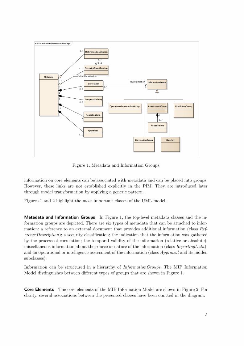
Figure 1: Metadata and Information Groups
information on core elements can be associated with metadata and can be placed into groups.
However, these links are not established explicitly in the PIM. They are introduced later
through model transformation by applying a generic pattern.
Figures 1 and 2 highlight the most important classes of the UML model.
Metadata and Information Groups In Figure 1, the top-level metadata classes and the in-
formation groups are depicted. There are six types of metadata that can be attached to infor-
mation: a reference to an external document that provides additional information (class Ref-
erenceDescription); a security classification; the indication that the information was gathered
by the process of correlation; the temporal validity of the information (relative or absolute);
miscellaneous information about the source or nature of the information (class ReportingData);
and an operational or intelligence assessment of the information (class Appraisal and its hidden
subclasses).
Information can be structured in a hierarchy of InformationGroups. The MIP Information
Model distinguishes between different types of groups that are shown in Figure 1.
Core Elements The core elements of the MIP Information Model are shown in Figure 2. For
clarity, several associations between the presented classes have been omitted in the diagram.
5
4 From the JC3IEDM to the MIP Information Model
At the heart of the model, there is a comprehensive taxonomy of Objects. In the diagram, only
the immediate children of Object are shown, i.e., Organisation, Materiel, Person, Feature, and
Facility. In total, the taxonomy of the current MIP Information Model comprises 147 classes.
Another part of the model deals with the specification of Actions. An Action may be either
a Task (i.e., a planned Action) or an Event (an incident, phenomenon, or occasion for which
no planning is known). The details of an action are specified by means of ActionResource,
ActionObjective, and ActionEffect.
In order to capture the free-text components of a plan in accordance with STANAG 2014,
a separate data structure is available that, among others, comprises classes PlanOrder and
PlanOrderComponent.
The fourth major submodel allows specifying the position and geometry of both actions and
objects. Again, for clarity, only root class Location and its direct children Point, Line, Surface,
and GeometricVolume are shown.
4 From the JC3IEDM to the MIP Information Model
When MIP decided to work on a new information model, there were two options:
1. Start from scratch and add new elements when they are actually needed.
2. Start with the existing JC3IEDM and apply a series of transformations.
Option 1 has the benefit that the new model is not convoluted with outdated concepts. (Please
note that the JC3IEDM is largely based on external data sources, such as NATO APP6 (Tac-
tical Symbols) or APP9 (Message Text Formats) that also underwent changes in recent years).
It is also easier to convince people that a specific feature is required than to argue why some
feature is not needed any more.
In contrary, option 2 has the advantage that it preserves the domain-specific knowledge of
more than two decades. The costs to reestablish this expertise would be unacceptable. For this
reason, the Multilateral Interoperability Programme opted for an evolutionary process.
4.1 General Transformation Approach
The transformation of the JC3IEDM proceeded in two steps that are described in the following.
4.1.1 ER to UML Transformation
In a first step, the Entity-Relationship model was transformed into a UML model. The trans-
formation was syntactically driven and defined on the ER and UML metamodels. For each
ER concept, a mapping on an equivalent UML concept was defined. For instance, an entity in
the ER model was mapped on a class in UML; domains with code lists became enumerations;
6

4.1 General Transformation Approach
class Core Elements
Action
ActionEffect
ActionObjective
ActionResource
AddressAffiliation
CandidateTargetList
Capability
Event FacilityFeature
Holding
Line
Location
Materiel
Object
ObjectTypeEstablishment
Organisation
OrganisationStructure
Person
PlanOrder PlanOrderComponent
Point
RuleOfEngagement
Surface
Task
Comment
GeometricVolume
GroupAccount
owners 0..*
Holding
properties 0..*
actualCapabilities0..*
0..1
nominalCapabilities
0..*
0..1
0..1
0..1
requirement
0..1
0..*
0..1
0..*
owner
1
0..*
authorities0..*
0..*
1
configurations0..*
1 0..*
0..1
minimumRequirements
0..*
1
compositions0..*
topic 0..1
subTopic 0..*
0..1
2..* {ordered}
0..1
0..*
0..1
0..1
0..1
0..1
0..1
0..*
0..10..1
1
0..*
1
0..*
reason0..1
0..*
10..*
0..*
0..*
Figure 2: Core Elements
entities, whose primary key attributes were foreign keys to two distinct classes, were mapped
onto many-to-many associations (possibly with an additional association class).
In addition, the integrity rules for the JC3IEDM (known as business rules) were specified in a
formal manner as constraints in the Object Constraint Language (OCL) [5] and added to the
respective UML classes.
Some initial measures have been taken to make the model platform-independent. For instance,
all primary and foreign key attributes (identifier and index attributes) were dropped during the
transformation. In addition, the discriminator codes that are needed in IDEF1X to represent
subtyping have been resolved.
7
4 From the JC3IEDM to the MIP Information Model
4.1.2 UML Model Restructuring
In a second step, the resulting UML model has been restructured. This time, both syntactic
and semantic changes were applied:
Syntactic Transformations Several syntactic changes have been applied to make the model
modular and easier to understand. The common characteristic of these transformations is
that they are potentially reversible3. Among others, the following transformations have been
performed:
� Merge the ObjectItem, ObjectType, and ObjectItemStatus hierarchies (see Section 4.2)
� Resolve business rules by an expanded class hierarchy (see Section 4.3)
� Change class, enumeration, and attribute names to reflect standard UML naming con-
ventions
Semantic Transformations The syntactic transformations mentioned above preserved the
semantics of the original JC3IEDM. However, great effort has also been made to transform the
MIP Information Model into a “stateless” model (cf. Section 3) and to clarify the meaning of
data elements. The following enumeration lists the most important modifications:
� Remove classes that were previously needed to establish “versioning” within the model
itself
� Decouple metadata and information groups from the core elements (see Section 3)
� Revise the properties of all associations and their respective association ends to meet
the design principle of a stateless, sourceless, and context-free model (uniqueness and
multiplicity)
� Revise the role names of association ends to clarify the meaning of associations
� Revise the navigability of association ends to support the generation of efficient exchange
schemas and implementations
� Identify non-shareable objects and adjust the aggregation type (composition vs. aggre-
gation vs. association)
� Revise all attribute and class definitions and simplify/modify class names to improve
comprehensibility
� Split up enumerations with a large number of code values to support modularization
� Replace enumerations with two values by the boolean primitive, where suitable
� Introduce a new UML profile based on UN/CEFACT’s Core Components Data Type
Catalogue (see Section 4.4)
3A reversible transformation may not result in exactly the same data structures as in the initial model but insemantically equivalent data structures.
8

4.2 Aligning and Merging Hierarchies
object-item-category-code
organisation-category-code
object-item-status-category-code
object-type-category-code
organisation-type-category-code
government-organisation-type-category-code
military-organisation-type-category-code
has / is-ascribed-tois-classified-as
P
is-used-as-a-classification-for
OBJECT-ITEMobject-item-id: NUMBER(20)
object-item-category-code: VARCHAR(6)object-item-name-text: VARCHAR(100)
ORGANISATIONorganisation-id.object-item-id: NUMBER(20) (FK)
organisation-category-code: VARCHAR(6)
CONVOYconvoy-id.organisation-id: NUMBER(20) (FK)
convoy-day-speed-rate: NUMBER(8,4)convoy-day-vehicle-gap-dimension: NUMBER(12,3)convoy-halt-duration: NUMBER(19)convoy-night-speed-rate: NUMBER(8,4)convoy-night-vehicle-gap-dimension: NUMBER(12,3)convoy-packet-gap-dimension: NUMBER(12,3)convoy-packet-size-count: NUMBER(9)
OBJECT-ITEM-STATUSobject-item-id: NUMBER(20) (FK)object-item-status-index: NUMBER(20)
object-item-status-category-code: VARCHAR(6)object-item-status-booby-trap-presence-code: VARCHAR(6)object-item-status-emission-control-code: VARCHAR(6)reporting-data-id: NUMBER(20) (FK)
OBJECT-ITEM-TYPEobject-item-id: NUMBER(20) (FK)object-type-id: NUMBER(20) (FK)object-item-type-index: NUMBER(20)
reporting-data-id: NUMBER(20) (FK)
OBJECT-TYPEobject-type-id: NUMBER(20)
object-type-category-code: VARCHAR(6)object-type-decoy-indicator-code: VARCHAR(6)object-type-name-text: VARCHAR(100)
ORGANISATION-STATUSorganisation-status-id.object-item-id: NUMBER(20) (FK)object-item-status-index: NUMBER(20) (FK)
organisation-status-operational-status-code: VARCHAR(6)organisation-status-operational-status-qualifier-code: VARCHAR(6)organisation-status-availability-code: VARCHAR(6)organisation-status-command-and-control-role-code: VARCHAR(6)organisation-status-commitment-status-code: VARCHAR(6)organisation-status-fire-mode-code: VARCHAR(6)organisation-status-cbrn-dress-state-code: VARCHAR(6)organisation-status-radiation-dose-quantity: NUMBER(6)organisation-status-readiness-code: VARCHAR(6)organisation-status-readiness-duration: NUMBER(19)organisation-status-reinforcement-code: VARCHAR(6)organisation-status-reserve-indicator-code: VARCHAR(6)organisation-status-training-code: VARCHAR(6)organisation-status-usage-status-code: VARCHAR(6)
ORGANISATION-TYPEorganisation-type-id.object-type-id: NUMBER(20) (FK)
organisation-type-category-code: VARCHAR(6)organisation-type-command-function-indicator-code: VARCHAR(6)organisation-type-command-and-control-category-code: VARCHAR(6)organisation-type-description-text: VARCHAR(50)
GOVERNMENT-ORGANISATION-TYPEgovernment-organisation-type-id.organisation-type-id: NUMBER(20) (FK)
government-organisation-type-category-code: VARCHAR(6)government-organisation-type-main-activity-code: VARCHAR(6)
MILITARY-ORGANISATION-TYPEmilitary-organisation-type-id.government-organisation-type-id: NUMBER(20) (FK)
military-organisation-type-category-code: VARCHAR(6)military-organisation-type-service-code: VARCHAR(6)
TASK-FORMATION-TYPEtask-formation-type-id.military-organisation-type-id: NUMBER(20) (FK)
task-formation-type-category-code: VARCHAR(6)
Figure 3: Required JC3IEDM Classes for Convoys
4.2 Aligning and Merging Hierarchies
The JC3IEDM has three tightly coupled hierarchies of entities: The OBJECT-ITEM hierarchy,
describing all kinds of specific objects, the OBJECT-TYPE hierarchy, describing static aspects,
and the OBJECT-ITEM-STATUS hierarchy, which captures aspects that are supposed to
change frequently. These hierarchies are associated with each other and a long list of business
rules defines how to use these hierarchies in combination.
For example, a person is described by attributes that
� are specific to an individual (PERSON ) such as the date of birth,
� define the type of person (PERSON-TYPE ) such as the military rank, and
� describe the person’s current status (PERSON-STATUS ), for example with respect to
health.
Even though conceptually these hierarchies are symmetrical (i.e., each individual should have a
corresponding type and status), the JC3IEDM is not modeled that way. This fact is more due
to restrictions and optimizations of the IDEF1X model than resulting from actual differences
between types and individuals in the real world. Since the JC3IEDM is a platform specific model
(PSM) and maps directly to database tables, it would not have made sense to model entities,
which effectively result in empty database tables with no attributes. Instead, empty tables were
eliminated by encoding the hierarchy in so-called incomplete subtypes, where necessary.
Figure 3 shows an excerpt of the OBJECT-ITEM-STATUS, OBJECT-ITEM, and OBJECT-
TYPE hierarchies that is relevant for modeling convoys.
Since the MIP Information Model is a platform-independent model (PIM), the optimization of
removing empty and unnecessary classes can be performed in the PIM-to-PSM transformation
9
4 From the JC3IEDM to the MIP Information Model
class Conv oy
MilitaryConv oy
«rate»+ daySpeedRate [0..1]+ nightSpeedRate [0..1]
«dimension»+ dayVehicleGapDimension [0..1]+ nightVehicleGapDimension [0..1]+ packetGapDimension [0..1]
«duration»+ haltDuration [0..1]
«quantity»+ packetSizeCount [0..1]
TaskFormation
MilitaryOrganisation
«code, type»+ serviceCode
Gov ernmentOrganisation
«code, type»+ mainActivityCode [0..1]
Organisation
«status, code»+ availabilityCode [0..1]+ cbrnDressStateCode [0..1]+ commandAndControlRoleCode [0..1]+ commitmentStatusCode [0..1]+ fireModeCode [0..1]+ operationalStatusCode+ operationalStatusQualifierCode [0..1]+ readinessCode [0..1]+ reinforcementCode [0..1]+ trainingCode [0..1]+ usageStatusCode [0..1]
«indicator, status»+ isInReserveIndicator [0..1]
«status, quantity»+ radiationDoseQuantity [0..1]
«duration, status»+ readinessDuration [0..1]
Object
«status, code»+ boobyTrapPresenceCode [0..1]+ emissionControlCode [0..1]
«code, status»+ hostil ityStatusCode [0..1]
«indicator, type»+ isDecoyIndicator
«name»+ name
«type, name»+ typeName
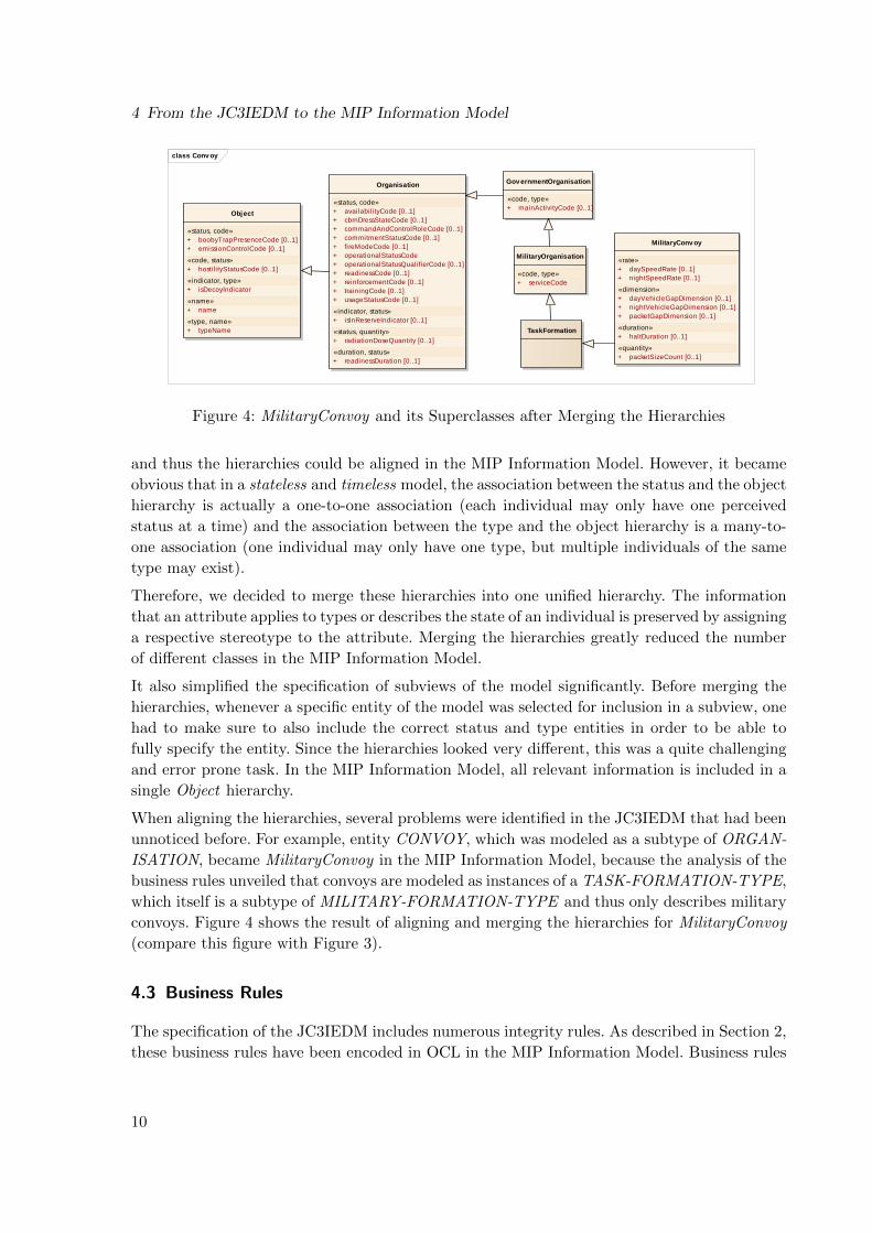
Figure 4: MilitaryConvoy and its Superclasses after Merging the Hierarchies
and thus the hierarchies could be aligned in the MIP Information Model. However, it became
obvious that in a stateless and timeless model, the association between the status and the object
hierarchy is actually a one-to-one association (each individual may only have one perceived
status at a time) and the association between the type and the object hierarchy is a many-to-
one association (one individual may only have one type, but multiple individuals of the same
type may exist).
Therefore, we decided to merge these hierarchies into one unified hierarchy. The information
that an attribute applies to types or describes the state of an individual is preserved by assigning
a respective stereotype to the attribute. Merging the hierarchies greatly reduced the number
of different classes in the MIP Information Model.
It also simplified the specification of subviews of the model significantly. Before merging the
hierarchies, whenever a specific entity of the model was selected for inclusion in a subview, one
had to make sure to also include the correct status and type entities in order to be able to
fully specify the entity. Since the hierarchies looked very different, this was a quite challenging
and error prone task. In the MIP Information Model, all relevant information is included in a
single Object hierarchy.
When aligning the hierarchies, several problems were identified in the JC3IEDM that had been
unnoticed before. For example, entity CONVOY, which was modeled as a subtype of ORGAN-
ISATION, became MilitaryConvoy in the MIP Information Model, because the analysis of the
business rules unveiled that convoys are modeled as instances of a TASK-FORMATION-TYPE,
which itself is a subtype of MILITARY-FORMATION-TYPE and thus only describes military
convoys. Figure 4 shows the result of aligning and merging the hierarchies for MilitaryConvoy
(compare this figure with Figure 3).
4.3 Business Rules
The specification of the JC3IEDM includes numerous integrity rules. As described in Section 2,
these business rules have been encoded in OCL in the MIP Information Model. Business rules
10

4.3 Business Rules
��������������������� ��� ������������������������ ���
��������� ���� ��
�����������
������
����� �� ���������������� ������
����� ������
����� ������
������������������� ���������������� ���������������
class BiologicalMateriel
ConsumableMateriel
BiologicalMateriel
«code, type»+ categoryCode+ persistencyCode [0..1]+ subcategoryCode [0..1]
«enumeration»BiologicalMaterielCategoryCode
«codeValue, enum» BACTRL TOXIN TOXMAT VIRAL
«enumeration»BiologicalMaterielSubcategoryCode
«codeValue, enum» CHLMYD RCKETS
Figure 5: JC3IEDM Business Rules for BiologicalMateriel (Adapted)
that are available in a formal language rather than in free-text format are a significant enhance-
ment. They allow developing validation tools that interpret the OCL constraints at run-time.
Nonetheless, for the sake of simplicity, it is still preferable to reduce the number of business
rules.
Many business rules of the JC3IEDM specify allowed combinations of categoryCode and subcat-
egoryCode attribute values within a single entity. This construct effectively specifies a hierarchy
of subtypes by using two attributes. These subtypes could be modeled explicitly by adding new
subclasses, eliminating the need for business rules.
A simple example is the class BiologicalMateriel, which originally had valid values for its sub-
categoryCode attribute only in one specific case, as shown in Figure 5. By introducing a new
subclass Bacterial, the subcategoryCode attribute could be moved to this new class and be“pro-
moted” to a categoryCode attribute. Furthermore, the value BACTRL was removed from the
list of category codes, and the categoryCode attribute of class BiologicalMateriel was moved to
a new subclass OtherBiologicalMateriel. Now, the business rule could be removed completely,
as it is modeled explicitly in the new structure shown in Figure 6.
11

5 Model Transformations
class BiologicalMateriel
ConsumableMateriel
BiologicalMateriel
«code, type»+ persistencyCode [0..1]
Bacterial
«code, type»+ categoryCode [0..1]
OtherBiologicalMateriel
«code, type»+ categoryCode
«enumeration»BacterialCategoryCode
«codeValue, enum» CHLMYD RCKETS
«enumeration»OtherBiologicalMaterielCategoryCode
«codeValue, enum» TOXIN TOXMAT VIRAL
Figure 6: Expanded Class Structure for BiologicalMateriel
4.4 UML Profile
The MIP Information Model makes use of a UML profile, i.e., a metamodel, that was largely
inspired by the UN/CEFACT Core Components Data Type Catalogue [8]. The UML profile
clarifies the semantics of data elements by means of representation terms. For example, it
distinguishes between text, name, and identifier attributes, whereas the JC3IEDM makes no
semantic distinction between them. Moreover, the profile defines metadata for attributes and
classes, such as the minimum and maximum length of text attributes.
Representation terms are specified as stereotypes in the UML profile. If a stereotype is assigned
to an attribute, it automatically inherits a number of tagged values, for which the data modeler
has to specify proper values (such as the aforementioned minimum text length). The use of
stereotypes/representation terms is depicted, e.g., in Figure 4. The attributes of MilitaryConvoy
have four different stereotypes, namely rate, dimension, duration, and quantity.
5 Model Transformations
The MIP Information Model is used as a starting point for various transformations in the
spirit of the Model Driven Architecture (MDA) approach4. As it is also used to describe the
operational information exchange requirements, it should be as understandable as possible
to humans and computers alike. This leads to a difficult trade-off of modeling some aspects
more explicitly in order to allow for simpler transformations versus hiding some aspects in the
metadata or business rules of the model.
In this section, we will describe some transformations and algorithms that can be applied to
the model in order to make it more suitable for actual information exchange and to easily
generate proper platform-specific models.
4The MDA approach facilitates the generation of technical specifications and code from more abstract, humanreadable models. For further information on MDA see [4].
12
5.1 Generating Model Subviews
class Subv iewMaster
Point
«coordinate»+ latitudeCoordinate :Decimal+ longitudeCoordinate :Decimal
«code»+ latitudePrecisionCode :AnglePrecisionCode [0..1]+ longitudePrecisionCode :AnglePrecisionCode [0..1]
Location
LineSurface
PolygonArea
0..12..* {ordered}
+boundary 1
0..1
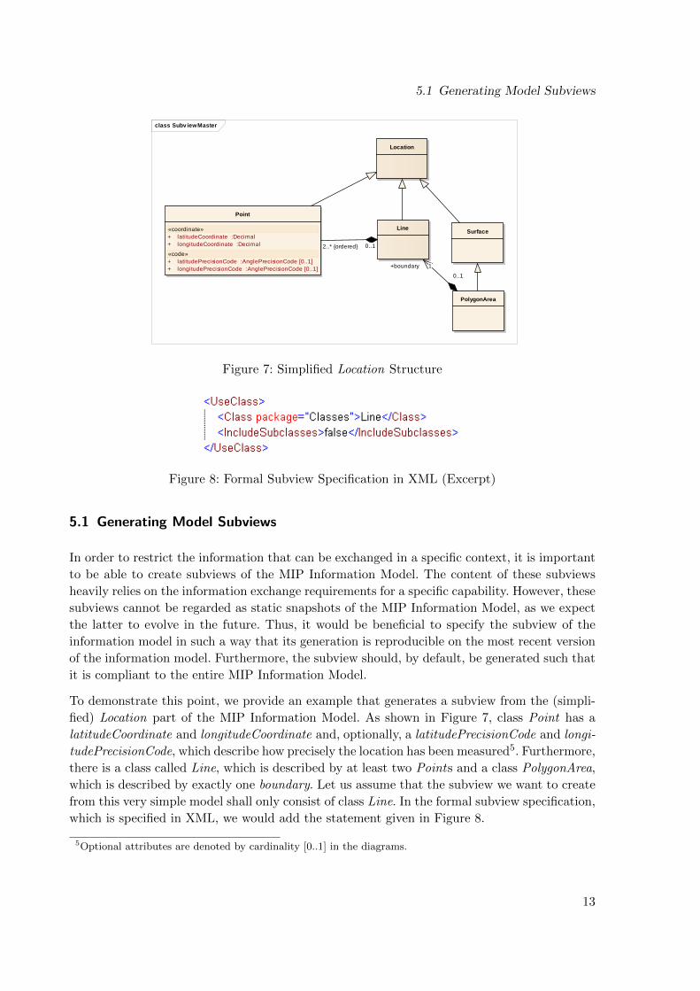
Figure 7: Simplified Location Structure
Figure 8: Formal Subview Specification in XML (Excerpt)
5.1 Generating Model Subviews
In order to restrict the information that can be exchanged in a specific context, it is important
to be able to create subviews of the MIP Information Model. The content of these subviews
heavily relies on the information exchange requirements for a specific capability. However, these
subviews cannot be regarded as static snapshots of the MIP Information Model, as we expect
the latter to evolve in the future. Thus, it would be beneficial to specify the subview of the
information model in such a way that its generation is reproducible on the most recent version
of the information model. Furthermore, the subview should, by default, be generated such that
it is compliant to the entire MIP Information Model.
To demonstrate this point, we provide an example that generates a subview from the (simpli-
fied) Location part of the MIP Information Model. As shown in Figure 7, class Point has a
latitudeCoordinate and longitudeCoordinate and, optionally, a latitudePrecisionCode and longi-
tudePrecisionCode, which describe how precisely the location has been measured5. Furthermore,
there is a class called Line, which is described by at least two Points and a class PolygonArea,
which is described by exactly one boundary. Let us assume that the subview we want to create
from this very simple model shall only consist of class Line. In the formal subview specification,
which is specified in XML, we would add the statement given in Figure 8.
5Optional attributes are denoted by cardinality [0..1] in the diagrams.
13

5 Model Transformations
class Subv iewAfter
Line
Location
Point
«coordinate»+ latitudeCoordinate :Decimal+ longitudeCoordinate :Decimal
0..12..*{ordered}
Figure 9: Resulting Minimal Compliant Subview
The subview generator tool would then traverse the MIP Information Model and include all
required attributes, associations, and classes, taking into account the constraints of the model.
The resulting subview is shown in Figure 9.
By default, the generated subview will include all superclasses of a class, all mandatory at-
tributes, and all mandatory associations. This means that if the model changes and, e.g., a
new mandatory attribute is introduced in class Line, re-running the subview generator will
automatically add the missing attribute to the subview.
5.2 Transformations of the MIP Information Model
Apart from generating small, semantically complete subsets of the MIP Information Model,
other possible transformations have been identified, which either add aspects to the model that
have been deliberately removed from the MIP Information Model or make certain aspects of
the model more explicit.
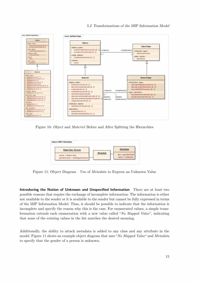
Extracting the Type Hierarchy In some cases, it may be necessary to exchange information
on catalogued types. For example, one capability may require exchanging information about
which types of vehicle (VehicleTypes) are able to pass a certain terrain. Thus, it may become
necessary to recreate the type hierarchy that was merged with the Object hierarchy as described
in Section 4.2. This transformation introduces a new Type class for each subclass in the Object
hierarchy and moves all attributes and association ends that have the stereotype <<type>>
(or <<typeRole>> for association ends) to the newly created class. The subclass of Object
and the corresponding subclass of ObjectType will then have a subset6 relationship as shown
in Figure 10.
6The subsets property on an association end describes that the association defines a subset of another associ-ation, effectively replacing the more generic association of the superclass.
14
5.2 Transformations of the MIP Information Model
class SplitItemTypeBefore
Materiel
«status, code»+ bodyColourCode [0..1]+ demolitionStatusCode [0..1]+ markingCode [0..1]+ markingColourCode [0..1]+ operationalStatusCode+ operationalStatusModeCode [0..1]+ operationalStatusQualifierCode [0..1]+ usageStatusCode [0..1]
«indicator, status»+ isInReserveIndicator [0..1]
«dimension, type»+ issuingHeightDimension [0..1]+ issuingLengthDimension [0..1]+ issuingWidthDimension [0..1]
«identifier»+ lotIdentifier [0..1]+ serialNumberIdentifier [0..1]
«type, identifier»+ reportableItemIdentifier [0..1]+ stockNumberIdentifier [0..1]
«code, type»+ supplyClassCode [0..1]
Object
«status, code»+ boobyTrapPresenceCode [0..1]+ emissionControlCode [0..1]
«code, status»+ hostil ityStatusCode [0..1]
«indicator, type»+ isDecoyIndicator
«name»+ name
«type, name»+ typeName
class SplitItemType
Object
«status, code»+ boobyTrapPresenceCode [0..1]+ emissionControlCode [0..1]
«code, status»+ hostil i tyStatusCode [0..1]
«name»+ name
ObjectType
«indicator, type»+ isDecoyIndicator
«type, name»+ typeName
Materiel
«status, code»+ bodyColourCode [0..1]+ demolitionStatusCode [0..1]+ markingCode [0..1]+ markingColourCode [0..1]+ operationalStatusCode+ operationalStatusModeCode [0..1]+ operationalStatusQualifierCode [0..1]+ usageStatusCode [0..1]
«indicator, status»+ isInReserveIndicator [0..1]
«identifier»+ lotIdentifier [0..1]+ serialNumberIdentifier [0..1]
MaterielType
«dimension, type»+ issuingHeightDimension [0..1]+ issuingLengthDimension [0..1]+ issuingWidthDimension [0..1]
«type, identifier»+ reportableItemIdentifier [0..1]+ stockNumberIdentifier [0..1]
+instance
0..*{subsetsinstance}
+classification
1{subsetsclassification}
+classification
1
+instance
0..*
Figure 10: Object and Materiel Before and After Splitting the Hierarchies
object NMV Metadata
Robin Doe :Person
name = Robin DoegenderCode = NoMappedValue
:Metadata
:KeyValue
key = genderCodevalue = Unknown
Figure 11: Object Diagram – Use of Metadata to Express an Unknown Value
Introducing the Notion of Unknown and Unspecified Information There are at least two
possible reasons that require the exchange of incomplete information: The information is either
not available to the sender or it is available to the sender but cannot be fully expressed in terms
of the MIP Information Model. Thus, it should be possible to indicate that the information is
incomplete and specify the reason why this is the case. For enumerated values, a simple trans-
formation extends each enumeration with a new value called “No Mapped Value”, indicating
that none of the existing values in the list matches the desired meaning.
Additionally, the ability to attach metadata is added to any class and any attribute in the
model. Figure 11 shows an example object diagram that uses“No Mapped Value“ and Metadata
to specify that the gender of a person is unknown.
15
5 Model Transformations
class BiologicalMaterielComplete
ConsumableMateriel
BiologicalMateriel
«code, type»+ persistencyCode [0..1]
Chlamydia Rickettsiae
Bacterial
Toxin
OtherBiologicalMateriel
ToxicIndustrialMaterial Viral
Figure 12: Transformation of categoryCode Attributes to Subclasses
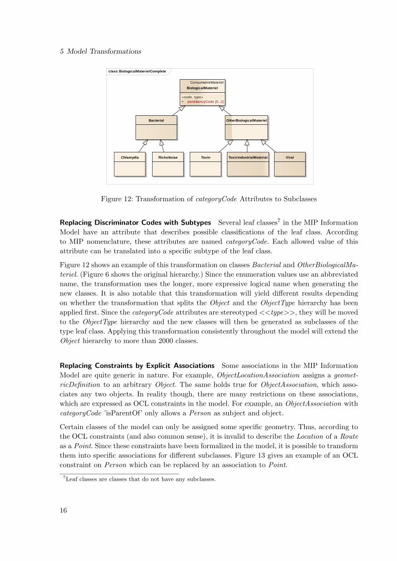
Replacing Discriminator Codes with Subtypes Several leaf classes7 in the MIP Information
Model have an attribute that describes possible classifications of the leaf class. According
to MIP nomenclature, these attributes are named categoryCode. Each allowed value of this
attribute can be translated into a specific subtype of the leaf class.
Figure 12 shows an example of this transformation on classes Bacterial and OtherBiologicalMa-
teriel. (Figure 6 shows the original hierarchy.) Since the enumeration values use an abbreviated
name, the transformation uses the longer, more expressive logical name when generating the
new classes. It is also notable that this transformation will yield different results depending
on whether the transformation that splits the Object and the ObjectType hierarchy has been
applied first. Since the categoryCode attributes are stereotyped <<type>>, they will be moved
to the ObjectType hierarchy and the new classes will then be generated as subclasses of the
type leaf class. Applying this transformation consistently throughout the model will extend the
Object hierarchy to more than 2000 classes.
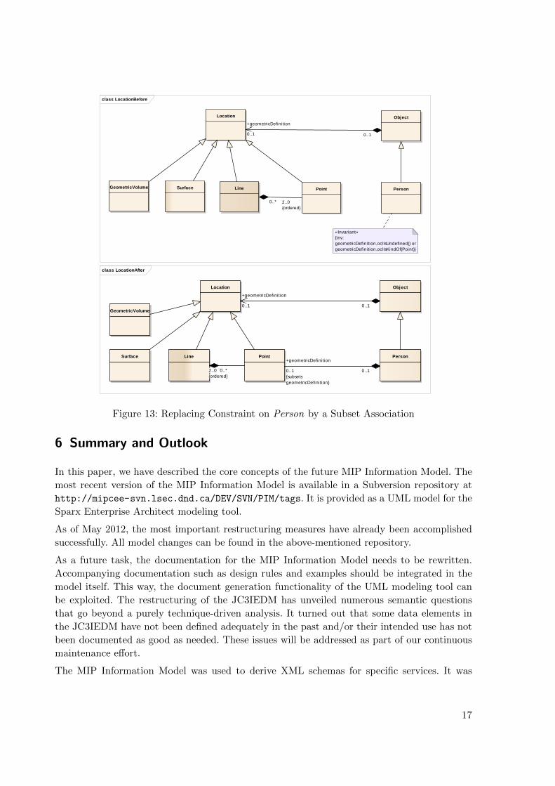
Replacing Constraints by Explicit Associations Some associations in the MIP Information
Model are quite generic in nature. For example, ObjectLocationAssociation assigns a geomet-
ricDefinition to an arbitrary Object. The same holds true for ObjectAssociation, which asso-
ciates any two objects. In reality though, there are many restrictions on these associations,
which are expressed as OCL constraints in the model. For example, an ObjectAssociation with
categoryCode ’isParentOf’ only allows a Person as subject and object.
Certain classes of the model can only be assigned some specific geometry. Thus, according to
the OCL constraints (and also common sense), it is invalid to describe the Location of a Route
as a Point. Since these constraints have been formalized in the model, it is possible to transform
them into specific associations for different subclasses. Figure 13 gives an example of an OCL
constraint on Person which can be replaced by an association to Point.
7Leaf classes are classes that do not have any subclasses.
16
class LocationBefore
Location
GeometricVolume Line PointSurface
Object
Person
«Invariant»{inv: geometricDefinition.oclIsUndefined() or geometricDefinition.oclIsKindOf(Point)}
+geometricDefinition
0..1 0..1
2..0{ordered}
0..*
class LocationAfter
Location
GeometricVolume
Line PointSurface
Object
Person
0..1
+geometricDefinition
0..1{subsetsgeometricDefinition}
2..0{ordered}
0..*
+geometricDefinition
0..1 0..1
Figure 13: Replacing Constraint on Person by a Subset Association
6 Summary and Outlook
In this paper, we have described the core concepts of the future MIP Information Model. The
most recent version of the MIP Information Model is available in a Subversion repository at
http://mipcee-svn.lsec.dnd.ca/DEV/SVN/PIM/tags. It is provided as a UML model for the
Sparx Enterprise Architect modeling tool.
As of May 2012, the most important restructuring measures have already been accomplished
successfully. All model changes can be found in the above-mentioned repository.
As a future task, the documentation for the MIP Information Model needs to be rewritten.
Accompanying documentation such as design rules and examples should be integrated in the
model itself. This way, the document generation functionality of the UML modeling tool can
be exploited. The restructuring of the JC3IEDM has unveiled numerous semantic questions
that go beyond a purely technique-driven analysis. It turned out that some data elements in
the JC3IEDM have not been defined adequately in the past and/or their intended use has not
been documented as good as needed. These issues will be addressed as part of our continuous
maintenance effort.
The MIP Information Model was used to derive XML schemas for specific services. It was
17

References
possible to demonstrate that the MDA approach allows producing schema definitions with little
effort (less than one person-day) and with full traceability to the MIP Information Model.
By transforming the JC3IEDM into a platform-independent model in UML that lifts many
of the former restrictions and workarounds, the Multilateral Interoperability Programme has
produced a solid foundation for a future interoperability solution. We believe many C2 com-
munities – not just MIP – can benefit from the new MIP Information Model.
References
[1] Gerz, M. & Meyer, O.: Defining C2 Semantics by a Platform-Independent JC3IEDM. In-
ternational Journal for Intelligent Defence Support Systems. Special Issue on Command
and Control Ontologies, Vol. 4, No. 3, pp. 263–285, 2011. 2
[2] Multilateral Interoperability Programme (MIP): MIP Website. https://mipsite.lsec.
dnd.ca/Pages/Default.aspx. (Last visited on 04 May 2011). 1
[3] Multilateral Interoperability Programme (MIP): JC3IEDM Baseline 3.1.4. Octo-
ber 2009, https://mipsite.lsec.dnd.ca/Public%20Document%20Library/Forms/
AllItems.aspx?RootFolder=%2FPublic%20Document%20Library%2F04-Baseline_3.1%
2FInterface-Specification%2FJC3IEDM. (Last visited on 04 May 2012). 1
[4] Object Management Group (OMG): Model-driven architecture, http://www.omg.org/mda/
index.htm. (Last visited on 04 May 2012). 2, 12
[5] Object Management Group (OMG): Object Constraint Language. January 2012, http:
//www.omg.org/spec/OCL/. (Last visited on 04 May 2012). 7
[6] Object Management Group (OMG): Shared Operational Picture Exchange Services
(SOPES) Information Exchange Data Model (IEDM) Version 1.0. May 2011, http:
//www.omg.org/spec/SOPES/. (Last visited on 04 May 2012). 1
[7] Simulation Interoperability Standards Organization (SISO): C-BML PDG – Coali-
tion - Battle Management Language, http://www.sisostds.org/StandardsActivities/
DevelopmentGroups/CBMLPDGCoalitionBattleManagementLanguage.aspx. (Last visited
on 04 May 2012). 1
[8] United Nations Centre for Trade Facilitation and Electronic Business (UN/CEFACT): Core
Components Data Type Catalogue Version 3.0. September 2009, http://www.unece.org/
fileadmin/DAM/cefact/codesfortrade/CCTS-CatalogueVersion3.pdf. (Last visited on
04 May 2012) 12
18