Embed Size (px)
Citation preview
17th March 2005 Bernardo Mota / CERN - PH
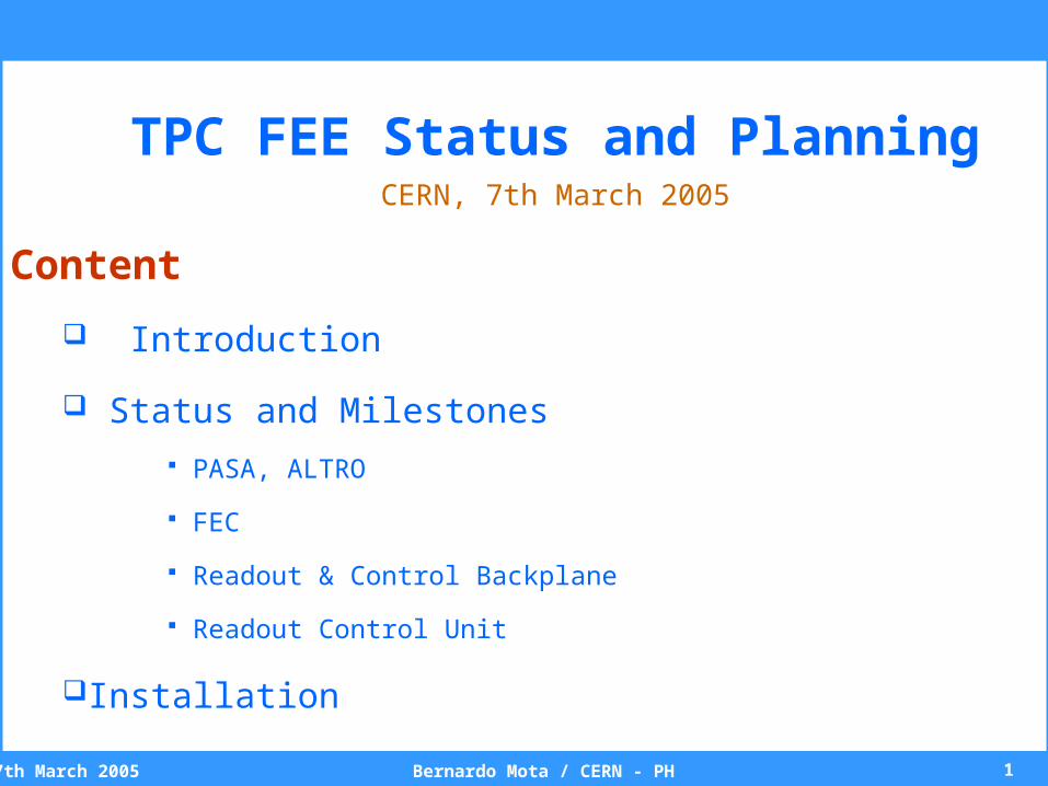
TPC FEE Status and PlanningCERN, 7th March 2005
Content
Introduction
Status and Milestones
PASA, ALTRO
FEC
Readout & Control Backplane
Readout Control Unit
Installation
27th March 2005 Bernardo Mota / CERN - PH
anode wire
pad plane
drift region88s
PASA ADC DigitalCircuit
RAM
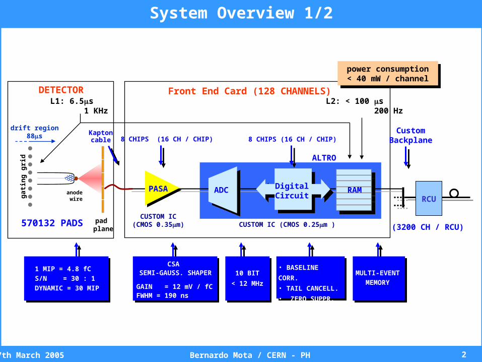
8 CHIPS (16 CH / CHIP) 8 CHIPS (16 CH / CHIP)
CUSTOM IC(CMOS 0.35m) CUSTOM IC (CMOS 0.25m )
DETECTOR Front End Card (128 CHANNELS)
570132 PADS (3200 CH / RCU)
gat
ing
gri
d ALTRO
RCU
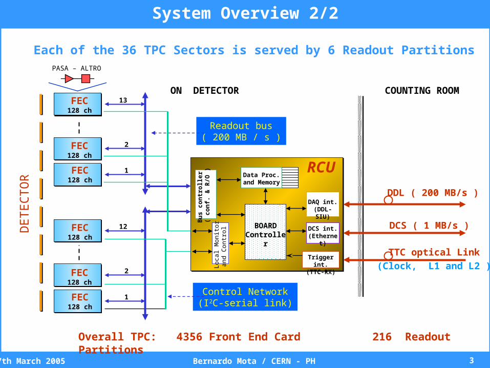
System Overview 1/2
Kaptoncable
CustomBackplane
power consumption< 40 mW / channel
power consumption< 40 mW / channel
L1: 6.5s 1 KHz
L2: < 100 s 200 Hz
1 MIP = 4.8 fC
S/N = 30 : 1
DYNAMIC = 30 MIP
CSA SEMI-GAUSS. SHAPER
GAIN = 12 mV / fCFWHM = 190 ns
10 BIT
< 12 MHz
• BASELINE CORR.
• TAIL CANCELL.
• ZERO SUPPR.
MULTI-EVENT
MEMORY
37th March 2005 Bernardo Mota / CERN - PH
Lo
cal M
onito
ra
nd
Co
ntr
ol BOARD
Controller
RCU
DCS ( 1 MB/s )
DDL ( 200 MB/s )
COUNTING ROOM
Each of the 36 TPC Sectors is served by 6 Readout Partitions
Readout bus( 200 MB / s )
Control Network(I2C-serial link)
ON DETECTOR
Overall TPC: 4356 Front End Card 216 Readout Partitions
Bu
s c
on
tro
ller
( c
on
f. &
R/O
)
FEC128 ch
1
1
2
2
12
13
DCS int.(Ethernet)
DAQ int.(DDL-SIU)
Trigger int.(TTC-RX)
FEC128 ch
FEC128 ch
FEC128 ch
FEC128 ch
FEC128 ch
PASA – ALTRO
DE
TE
CT
OR
TTC optical Link
(Clock, L1 and L2 )
Data Proc.and Memory
System Overview 2/2
47th March 2005 Bernardo Mota / CERN - PH
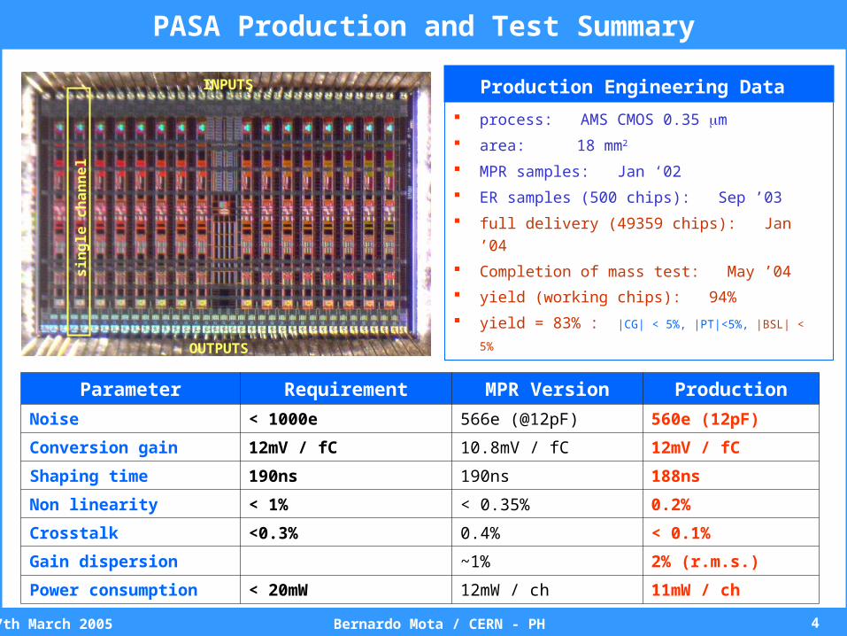
process: AMS CMOS 0.35 m
area: 18 mm2
MPR samples: Jan ‘02
ER samples (500 chips): Sep ’03
full delivery (49359 chips): Jan ’04
Completion of mass test: May ’04
yield (working chips): 94%
yield = 83% : |CG| < 5%, |PT|<5%, |BSL| < 5%
Production Engineering Data
Parameter Requirement MPR Version Production
Noise < 1000e 566e (@12pF) 560e (12pF)
Conversion gain 12mV / fC 10.8mV / fC 12mV / fC
Shaping time 190ns 190ns 188ns
Non linearity < 1% < 0.35% 0.2%
Crosstalk <0.3% 0.4% < 0.1%
Gain dispersion ~1% 2% (r.m.s.)
Power consumption < 20mW 12mW / ch 11mW / ch
PASA Production and Test Summary
INPUTSs
ing
le c
ha
nn
el
OUTPUTS
57th March 2005 Bernardo Mota / CERN - PH
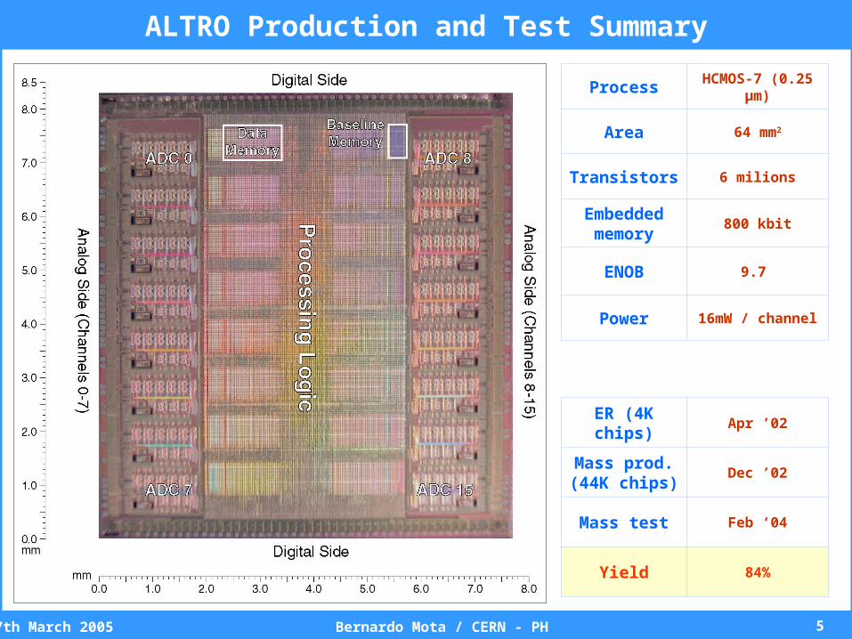
Process HCMOS-7 (0.25 µm)
Area 64 mm2
Transistors 6 milions
Embeddedmemory
800 kbit
ENOB 9.7
Power 16mW / channel
ER (4K chips) Apr ’02
Mass prod. (44K chips)
Dec ’02
Mass test Feb ‘04
Yield 84%
ALTRO Production and Test Summary
67th March 2005 Bernardo Mota / CERN - PH
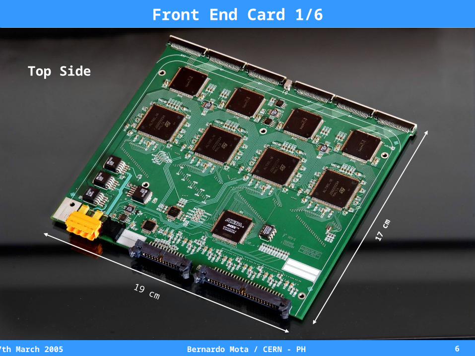
19 cm
17 c
m
Front End Card 1/6
Top Side
77th March 2005 Bernardo Mota / CERN - PH
Front End Card 2/6
Bottom Side
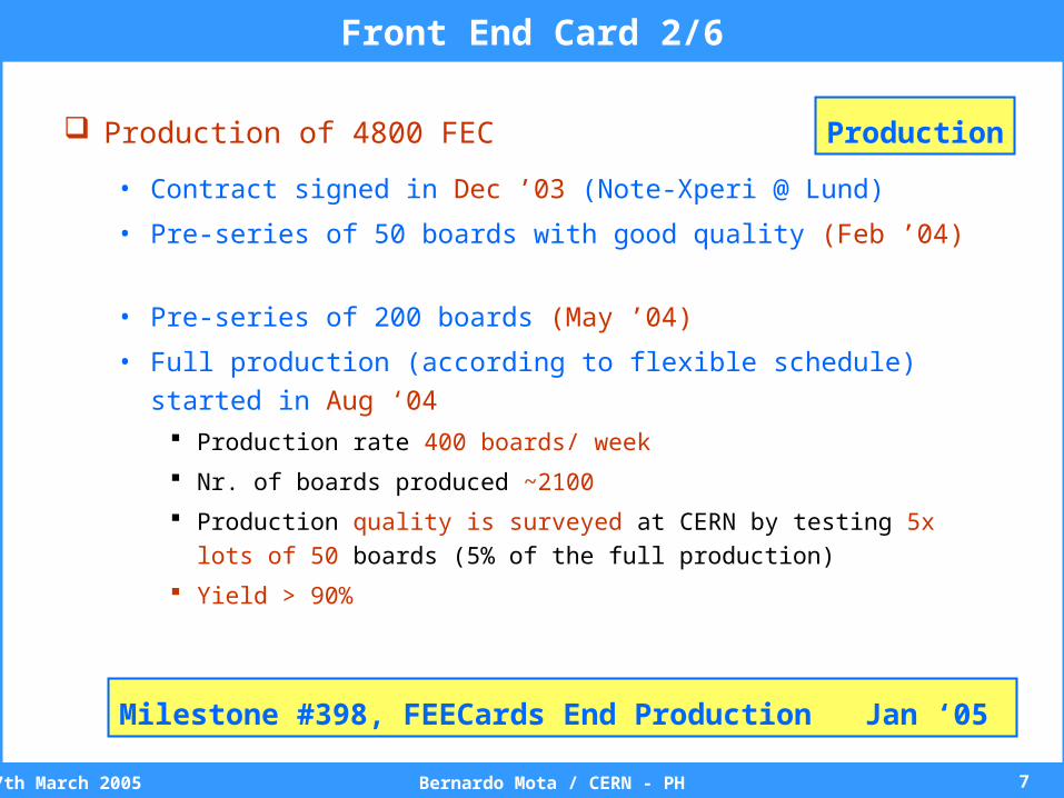
Production of 4800 FEC
• Contract signed in Dec ’03 (Note-Xperi @ Lund)
• Pre-series of 50 boards with good quality (Feb ’04)
• Pre-series of 200 boards (May ’04)
• Full production (according to flexible schedule) started in Aug ‘04 Production rate 400 boards/ week
Nr. of boards produced ~2100
Production quality is surveyed at CERN by testing 5x lots of 50 boards (5%
of the full production)
Yield > 90%
Milestone #398, FEECards End Production Jan ‘05
Production
87th March 2005 Bernardo Mota / CERN - PH
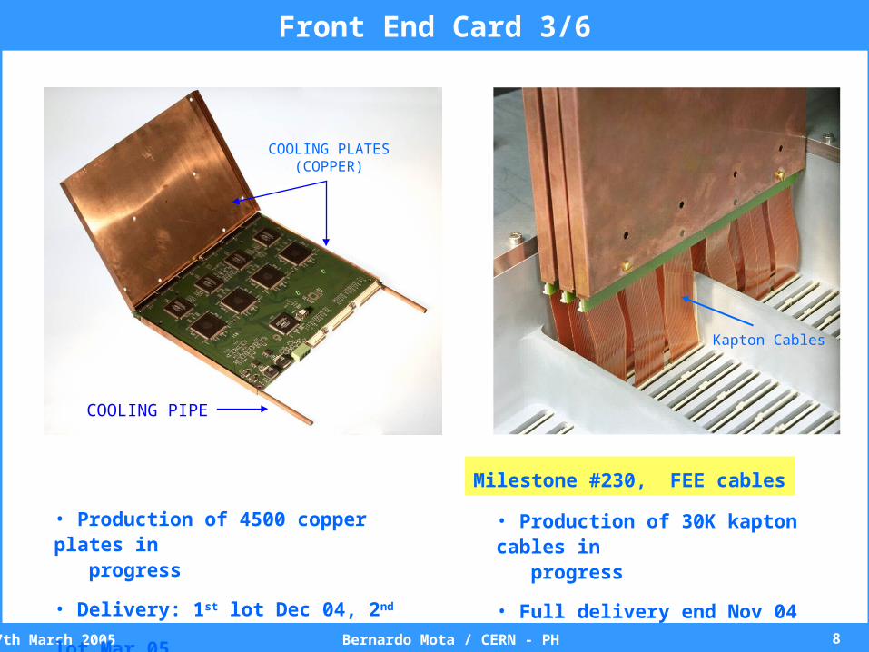
COOLING PLATES(COPPER)
COOLING PIPE
Kapton Cables
Front End Card 3/6
• Production of 30K kapton cables in progress
• Full delivery end Nov 04
Milestone #230, FEE cables
• Production of 4500 copper plates in progress
• Delivery: 1st lot Dec 04, 2nd lot Mar 05
97th March 2005 Bernardo Mota / CERN - PH
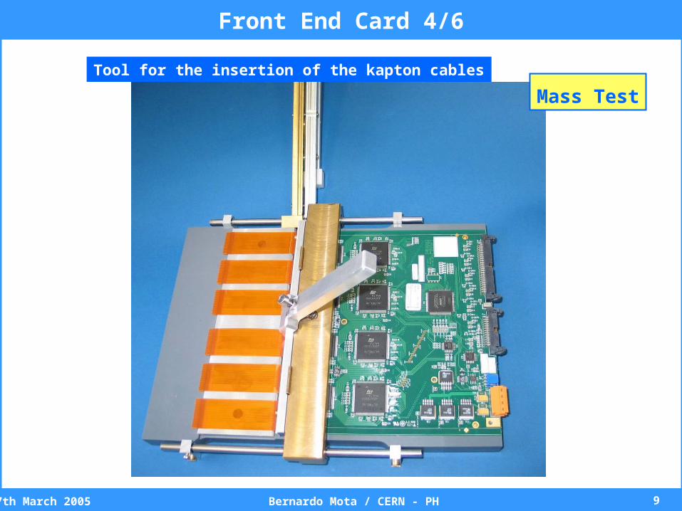
Front End Card 4/6
Mass Test
Tool for the insertion of the kapton cables
107th March 2005 Bernardo Mota / CERN - PH
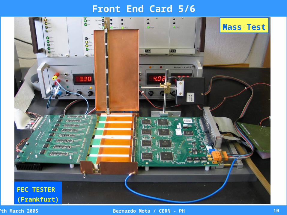
FEC TESTER
(Frankfurt)
Front End Card 5/6
Mass Test
117th March 2005 Bernardo Mota / CERN - PH
Front End Card 6/6
Bottom Side
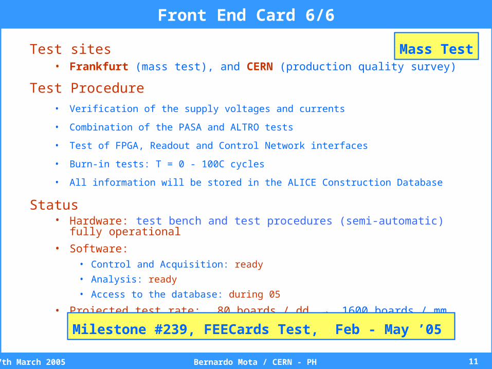
Test sites• Frankfurt (mass test), and CERN (production quality survey)
Test Procedure• Verification of the supply voltages and currents
• Combination of the PASA and ALTRO tests
• Test of FPGA, Readout and Control Network interfaces
• Burn-in tests: T = 0 - 100C cycles
• All information will be stored in the ALICE Construction Database
Status• Hardware: test bench and test procedures (semi-automatic) fully operational
• Software:• Control and Acquisition: ready
• Analysis: ready
• Access to the database: during 05
• Projected test rate: 80 boards / dd → 1600 boards / mm
Milestone #239, FEECards Test, Feb - May ’05
Mass Test
127th March 2005 Bernardo Mota / CERN - PH
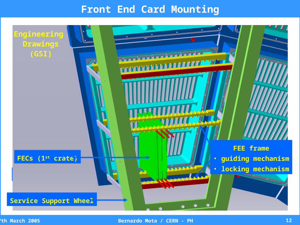
Front End Card Mounting
Engineering drawings(GSI)
3-sector model
Service Support Wheel
IROC
OROC
Engineering Drawings
(GSI)
FECs (1st crate)
Service Support Wheel
FEE frame
• guiding mechanism
• locking mechanism
137th March 2005 Bernardo Mota / CERN - PH
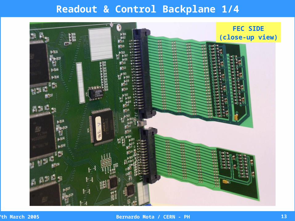
FEC SIDE(close-up view)
Readout & Control Backplane 1/4
147th March 2005 Bernardo Mota / CERN - PH
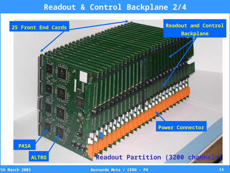
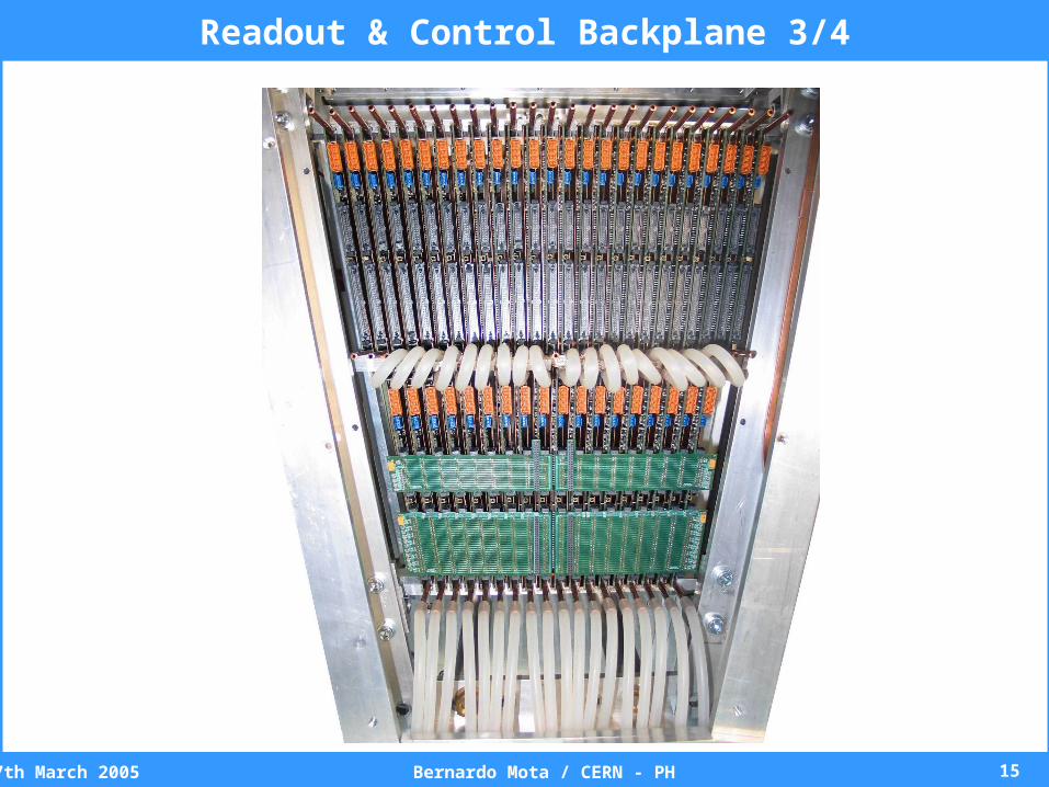
25 Front End Cards
ALTRO
PASA
Power Connector
Readout and Control
Backplane
Readout Partition (3200 channels)
Readout & Control Backplane 2/4
157th March 2005 Bernardo Mota / CERN - PH
Readout & Control Backplane 3/4
167th March 2005 Bernardo Mota / CERN - PH
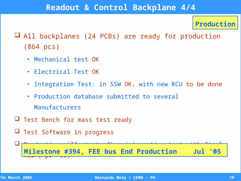
Readout & Control Backplane 4/4
All backplanes (24 PCBs) are ready for production (864 pcs)
• Mechanical test OK
• Electrical Test OK
• Integration Test: in SSW OK, with new RCU to be done
• Production database submitted to several Manufacturers
Test Bench for mass test ready
Test Software in progress
Production will start after integration test with final RCU (Apr ’05)
Milestone #394, FEE bus End Production Jul ‘05
Production

177th March 2005 Bernardo Mota / CERN - PH
DCS BOARD
(HEIDELBERG)
Excalibur
ARM-Processor
DDL – SIU
(DAQ)
RE
AD
OU
T C
ON
TR
OL
UN
IT
(BE
RG
EN
– CE
RN
)
Readout Control Unit
187th March 2005 Bernardo Mota / CERN - PH
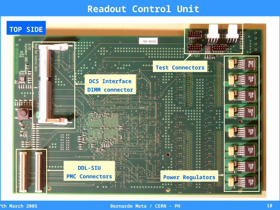
Readout Control Unit
DCS Interface
DIMM connector
DDL-SIU
PMC Connectors Power Regulators
Test Connectors
TOP SIDE
197th March 2005 Bernardo Mota / CERN - PH
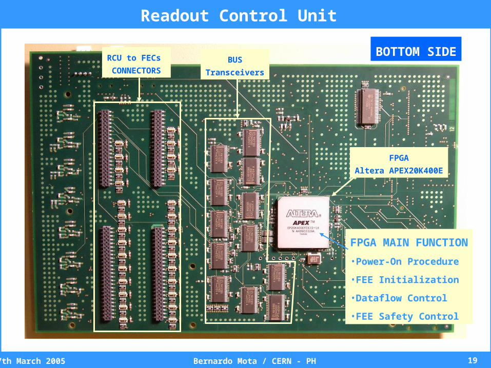
Readout Control Unit
FPGA MAIN FUNCTION
•Power-On Procedure
•FEE Initialization
•Dataflow Control
•FEE Safety Control
RCU to FECs
CONNECTORSBUS
Transceivers
FPGA
Altera APEX20K400E
BOTTOM SIDE
207th March 2005 Bernardo Mota / CERN - PH
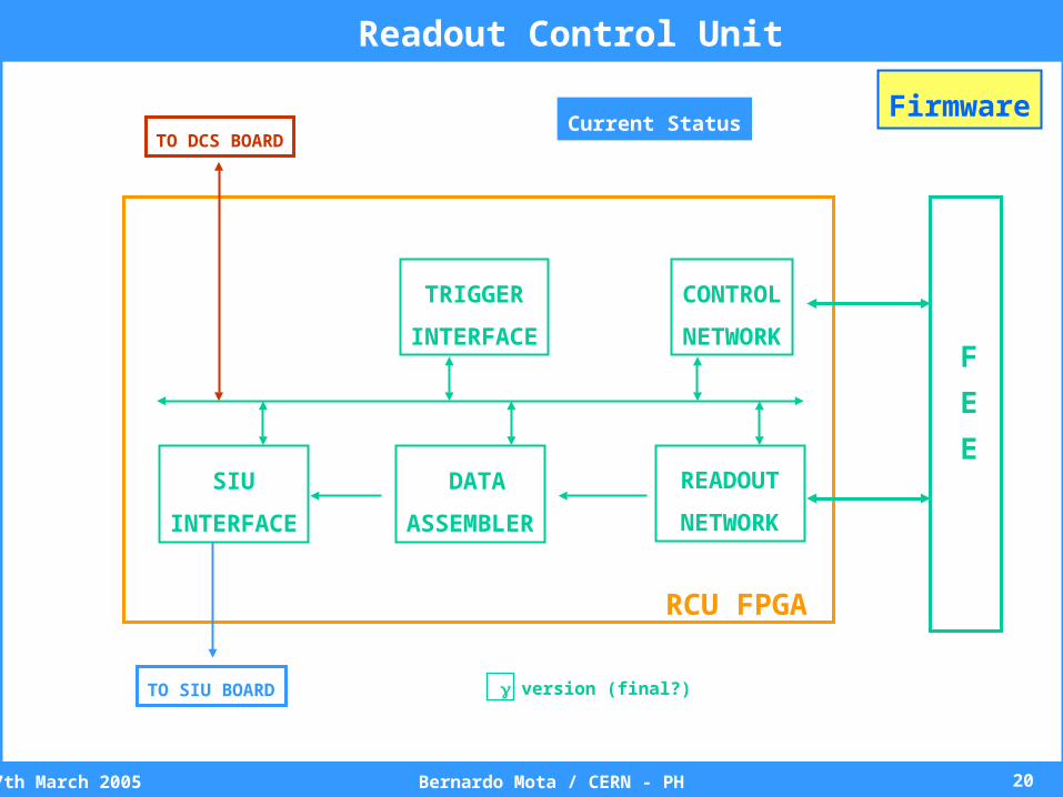
CONTROL
NETWORK
READOUT
NETWORK
DATA
ASSEMBLER
SIU
INTERFACE
TRIGGER
INTERFACE
RCU FPGA
TO DCS BOARD
TO SIU BOARD
F
E
E
version (final?)
Current StatusFirmware
Readout Control Unit
217th March 2005 Bernardo Mota / CERN - PH
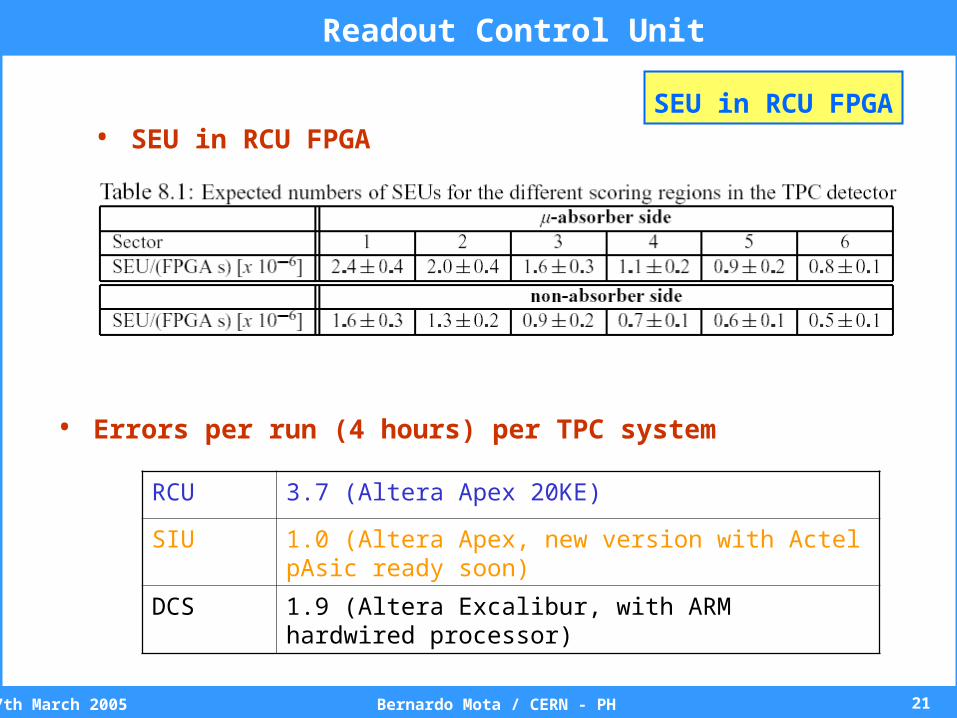
• SEU in RCU FPGA
Readout Control Unit
SEU in RCU FPGA
RCU 3.7 (Altera Apex 20KE)
SIU 1.0 (Altera Apex, new version with Actel pAsic ready soon)
DCS 1.9 (Altera Excalibur, with ARM hardwired processor)
• Errors per run (4 hours) per TPC system
227th March 2005 Bernardo Mota / CERN - PH
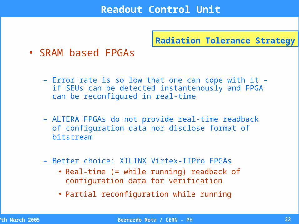
• SRAM based FPGAs
– Error rate is so low that one can cope with it – if SEUs can be detected instantenously and FPGA can be reconfigured in real-time
– ALTERA FPGAs do not provide real-time readback of configuration data nor disclose format of bitstream
– Better choice: XILINX Virtex-IIPro FPGAs
• Real-time (= while running) readback of configuration data for verification
• Partial reconfiguration while running
Readout Control Unit
Radiation Tolerance Strategy

237th March 2005 Bernardo Mota / CERN - PH
• Decide to migrate RCU-FPGA to XILINX
• Select appropriate device w.r.t. resources (e.g. number of
I/O cells)
• Decide to keep DCS board unchanged
• Port RCU design to new development environment
• Verify expected performance under irradiation– XILINX test @ OCL in August
– System test @ TSL Q1 205 with large beam spot
Readout Control Unit
Radiation Tolerance Strategy
247th March 2005 Bernardo Mota / CERN - PH
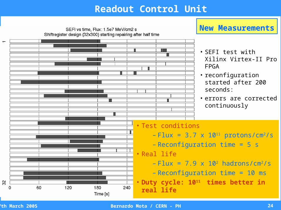
• SEFI test with Xilinx Virtex-II Pro FPGA
• reconfiguration started after 200 seconds:
• errors are corrected continuously
• Test conditions
– Flux = 3.7 x 10¹¹ protons/cm2/s
– Reconfiguration time = 5 s
• Real life
– Flux = 7.9 x 10² hadrons/cm2/s
– Reconfiguration time = 10 ms
• Duty cycle: 1011 times better in real life
Readout Control Unit
New Measurements
257th March 2005 Bernardo Mota / CERN - PH
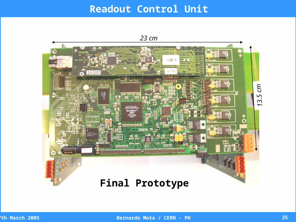
23 cm
13.5
cm
Readout Control Unit
Final Prototype
267th March 2005 Bernardo Mota / CERN - PH
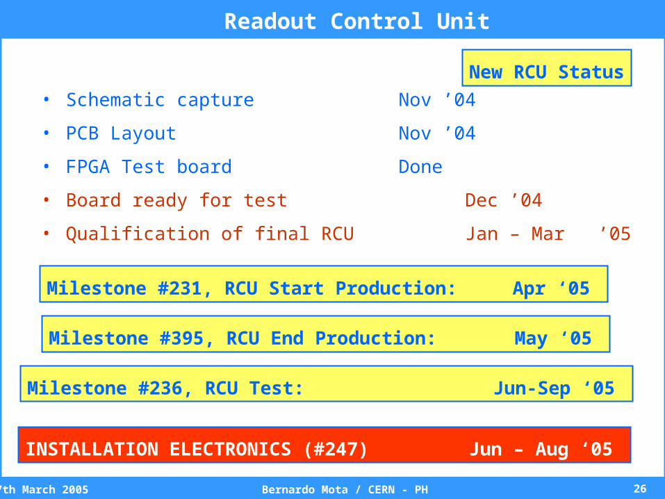
• Schematic capture Nov ’04
• PCB Layout Nov ’04
• FPGA Test board Done
• Board ready for test Dec ’04
• Qualification of final RCU Jan – Mar ’05
Readout Control Unit
New RCU Status
Milestone #231, RCU Start Production: Apr ‘05
Milestone #395, RCU End Production: May ‘05
Milestone #236, RCU Test: Jun-Sep ‘05
INSTALLATION ELECTRONICS (#247) Jun – Aug ‘05
277th March 2005 Bernardo Mota / CERN - PH
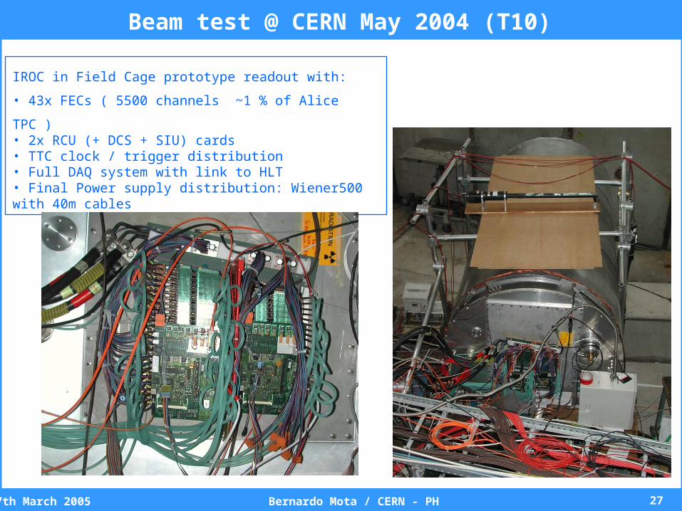
IROC in Field Cage prototype readout with:
• 43x FECs ( 5500 channels ~1 % of Alice TPC )• 2x RCU (+ DCS + SIU) cards • TTC clock / trigger distribution • Full DAQ system with link to HLT• Final Power supply distribution: Wiener500 with 40m cables
Beam test @ CERN May 2004 (T10)
287th March 2005 Bernardo Mota / CERN - PH
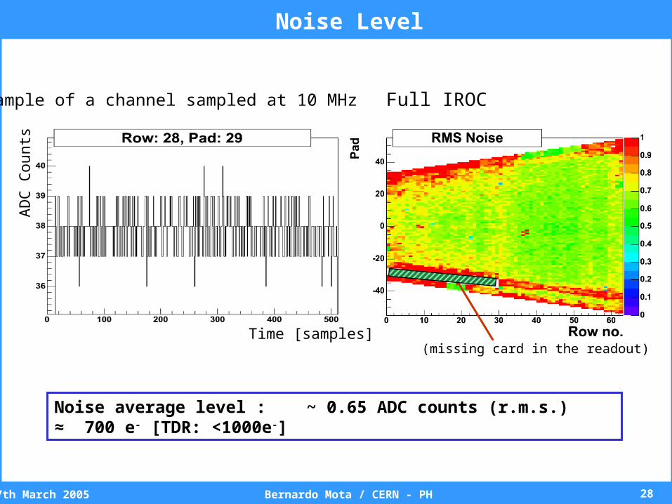
Example of a channel sampled at 10 MHz Full IROC
Noise average level : ~ 0.65 ADC counts (r.m.s.) ≈ 700 e- [TDR: <1000e-]
(missing card in the readout)Time [samples]
AD
C C
ount
sNoise Level
297th March 2005 Bernardo Mota / CERN - PH
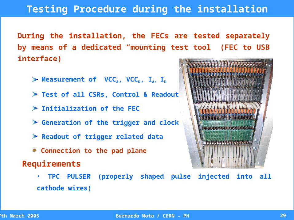
Testing Procedure during the installation
During the installation, the FECs are tested separately by means of a
dedicated “mounting test tool” (FEC to USB interface)
Measurement of VCCA, VCCD, IA, ID
Test of all CSRs, Control & Readout path
Initialization of the FEC
Generation of the trigger and clock signals
Readout of trigger related data
Connection to the pad plane
Requirements
• TPC PULSER (properly shaped pulse injected into all cathode wires)
307th March 2005 Bernardo Mota / CERN - PH
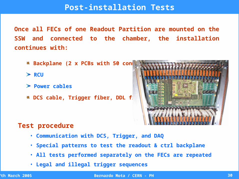
Once all FECs of one Readout Partition are mounted on the SSW and
connected to the chamber, the installation continues with:
Backplane (2 x PCBs with 50 connectors)
RCU
Power cables
DCS cable, Trigger fiber, DDL fiber
Test procedure
• Communication with DCS, Trigger, and DAQ
• Special patterns to test the readout & ctrl backplane
• All tests performed separately on the FECs are repeated
• Legal and illegal trigger sequences
Post-installation Tests