Embed Size (px)
Citation preview

Search... Go
Categories
Boards
Connectors
Hardware
Microcontrollers
Integrated Circuits
Passive Components
Semiconductors
LED/LCD
Buttons andSwitches
Cables
Sensors
Accessories
Kits & Modules
Tools
Other
Featured...
LED matrix 8x8 Red/Green37.8 x 37.8mm
Analogue to Digital Conversion on an ATmega168
13-Feb-2011 8:44amRead comments Leave a comment
Many AVR microcontrollers are capable of doing Analogue to Digital Conversion.The ATmega168 has 6 ports (8 ports on the SMD packages) that can be used foranalogue input. This tutorial shows you how.
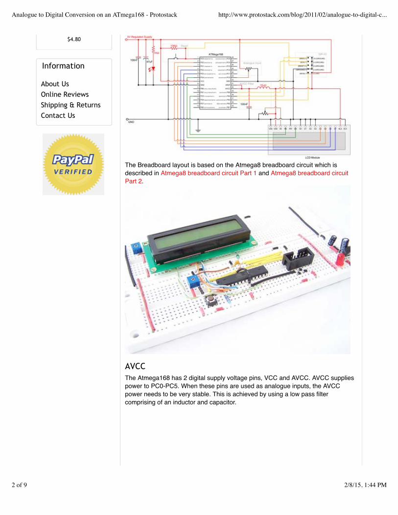
The circuitWe’ll be building the following circuit on a breadboard.
Home » Blog » Tutorials » Analogue to Digital Conversion on an ATmega168
About Blog Tutorials Library Contact
Login or Create Account
1800 335 330 Shopping Cart: Empty
Analogue to Digital Conversion on an ATmega168 - Protostack http://www.protostack.com/blog/2011/02/analogue-to-digital-c...
1 of 9 2/8/15, 1:44 PM
$4.80
Information
About UsOnline ReviewsShipping & ReturnsContact Us
The Breadboard layout is based on the Atmega8 breadboard circuit which isdescribed in Atmega8 breadboard circuit Part 1 and Atmega8 breadboard circuitPart 2.
AVCCThe Atmega168 has 2 digital supply voltage pins, VCC and AVCC. AVCC suppliespower to PC0-PC5. When these pins are used as analogue inputs, the AVCCpower needs to be very stable. This is achieved by using a low pass filtercomprising of an inductor and capacitor.
Analogue to Digital Conversion on an ATmega168 - Protostack http://www.protostack.com/blog/2011/02/analogue-to-digital-c...
2 of 9 2/8/15, 1:44 PM
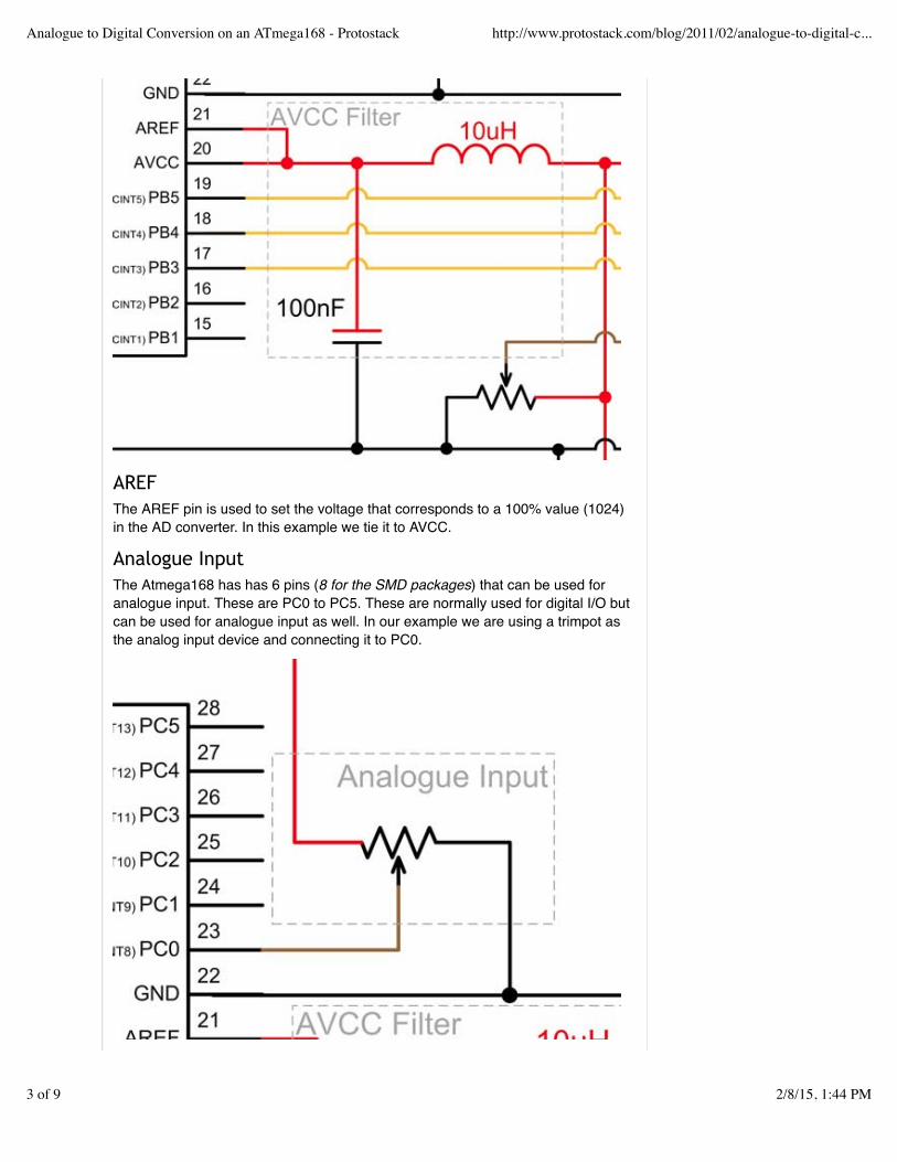
AREFThe AREF pin is used to set the voltage that corresponds to a 100% value (1024)in the AD converter. In this example we tie it to AVCC.
Analogue InputThe Atmega168 has has 6 pins (8 for the SMD packages) that can be used foranalogue input. These are PC0 to PC5. These are normally used for digital I/O butcan be used for analogue input as well. In our example we are using a trimpot asthe analog input device and connecting it to PC0.
Analogue to Digital Conversion on an ATmega168 - Protostack http://www.protostack.com/blog/2011/02/analogue-to-digital-c...
3 of 9 2/8/15, 1:44 PM

LCD displayWe’ve connected an LCD display to pins PD0 to PD5 and is used to displayanalogue readings. For more information on using LCD displays, please readCharacter LCD Displays – Part 2.
RegistersThe Atmega168 uses 6 different registers when performing analogue to digitalconversion. These are:
Register Description
ADMUX ADC Multiplexer Selection Register
ADCSRA ADC Control and Status Register A
ADCSRB ADC Control and Status Register B
DIDR0 Digital Input Disable Register 0
ADCL ADC Data Register – Low
ADCH ADC Data Register – High
The ADMUX register allows you to control:
The Reference VoltageLeft adjustment of results (used for 8 bit results)Selection of input channel
bit 7 6 5 4 3 2 1 0
ADMUX REFS1 REFS0 ADLAR - MUX3 MUX2 MUX1 MUX0
Read/Write R/W R/W R/W R R/W R/W R/W R/W
InitialValue
0 0 0 0 0 0 0 0
The reference voltage is controlled by REFS1 and REFS0. The default is to useAREF, but other options are available.
ADLAR is used for left shifting the converted data. This is useful when reading 8 bitvalues due to the fact that reading a 16 bit value is not an atomic operation.
MUX0 to MUX3 are used to select which input channel you wish to read. Thevalues 0000 to 0101 allow you to select ports PC0 to PC5, while the reservedvalues of 1110 and 1111 allow you to select 1.1V and 0V.
ADCSRA and ADCSRB are used to control the AD conversion process.
bit 7 6 5 4 3 2 1 0
ADCSRA ADEN ADSC ADATE ADIF ADIE ADPS2 ADPS1 ADPS0
Read/Write R/W R/W R/W R/W R/W R/W R/W R/W
InitialValue
0 0 0 0 0 0 0 0
Analogue to Digital Conversion on an ATmega168 - Protostack http://www.protostack.com/blog/2011/02/analogue-to-digital-c...
4 of 9 2/8/15, 1:44 PM
bit 7 6 5 4 3 2 1 0
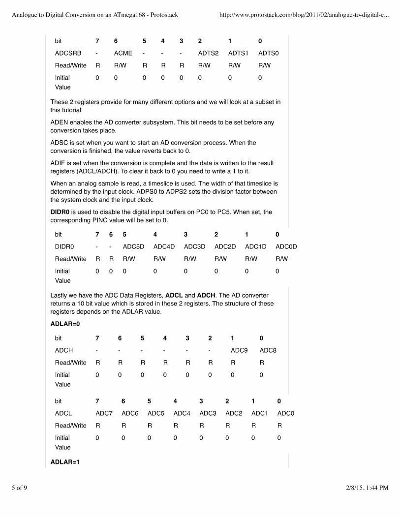
ADCSRB - ACME - - - ADTS2 ADTS1 ADTS0
Read/Write R R/W R R R R/W R/W R/W
InitialValue
0 0 0 0 0 0 0 0
These 2 registers provide for many different options and we will look at a subset inthis tutorial.
ADEN enables the AD converter subsystem. This bit needs to be set before anyconversion takes place.
ADSC is set when you want to start an AD conversion process. When theconversion is finished, the value reverts back to 0.
ADIF is set when the conversion is complete and the data is written to the resultregisters (ADCL/ADCH). To clear it back to 0 you need to write a 1 to it.
When an analog sample is read, a timeslice is used. The width of that timeslice isdetermined by the input clock. ADPS0 to ADPS2 sets the division factor betweenthe system clock and the input clock.
DIDR0 is used to disable the digital input buffers on PC0 to PC5. When set, thecorresponding PINC value will be set to 0.
bit 7 6 5 4 3 2 1 0
DIDR0 - - ADC5D ADC4D ADC3D ADC2D ADC1D ADC0D
Read/Write R R R/W R/W R/W R/W R/W R/W
InitialValue
0 0 0 0 0 0 0 0
Lastly we have the ADC Data Registers, ADCL and ADCH. The AD converterreturns a 10 bit value which is stored in these 2 registers. The structure of theseregisters depends on the ADLAR value.
ADLAR=0
bit 7 6 5 4 3 2 1 0
ADCH - - - - - - ADC9 ADC8
Read/Write R R R R R R R R
InitialValue
0 0 0 0 0 0 0 0
bit 7 6 5 4 3 2 1 0
ADCL ADC7 ADC6 ADC5 ADC4 ADC3 ADC2 ADC1 ADC0
Read/Write R R R R R R R R
InitialValue
0 0 0 0 0 0 0 0
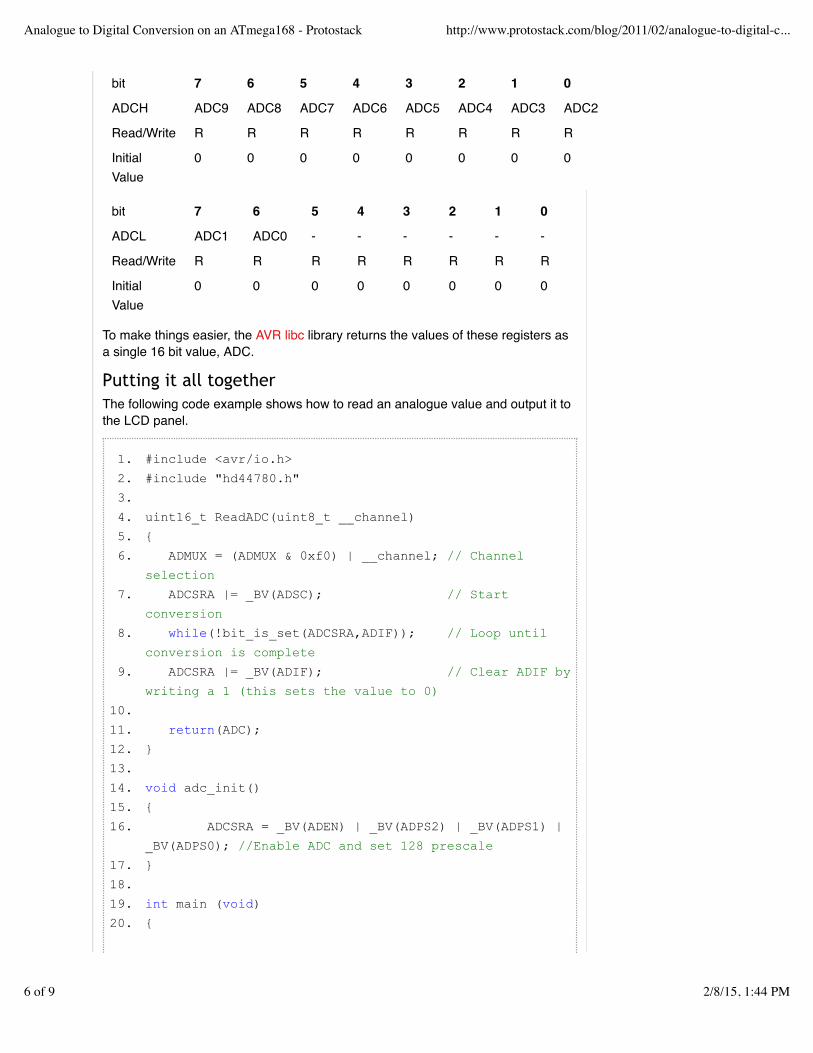
ADLAR=1
Analogue to Digital Conversion on an ATmega168 - Protostack http://www.protostack.com/blog/2011/02/analogue-to-digital-c...
5 of 9 2/8/15, 1:44 PM
bit 7 6 5 4 3 2 1 0
ADCH ADC9 ADC8 ADC7 ADC6 ADC5 ADC4 ADC3 ADC2
Read/Write R R R R R R R R
InitialValue
0 0 0 0 0 0 0 0
bit 7 6 5 4 3 2 1 0
ADCL ADC1 ADC0 - - - - - -
Read/Write R R R R R R R R
InitialValue
0 0 0 0 0 0 0 0
To make things easier, the AVR libc library returns the values of these registers asa single 16 bit value, ADC.
Putting it all togetherThe following code example shows how to read an analogue value and output it tothe LCD panel.
#include <avr/io.h>1.
#include "hd44780.h"2.
3.
uint16_t ReadADC(uint8_t __channel)4.
{5.
ADMUX = (ADMUX & 0xf0) | __channel; // Channel
selection
6.
ADCSRA |= _BV(ADSC); // Start
conversion
7.
while(!bit_is_set(ADCSRA,ADIF)); // Loop until
conversion is complete
8.
ADCSRA |= _BV(ADIF); // Clear ADIF by
writing a 1 (this sets the value to 0)
9.
10.
return(ADC);11.
}12.
13.
void adc_init()14.
{15.
ADCSRA = _BV(ADEN) | _BV(ADPS2) | _BV(ADPS1) |
_BV(ADPS0); //Enable ADC and set 128 prescale
16.
}17.
18.
int main (void)19.
{20.
Analogue to Digital Conversion on an ATmega168 - Protostack http://www.protostack.com/blog/2011/02/analogue-to-digital-c...
6 of 9 2/8/15, 1:44 PM
lcd_init();21.
adc_init();22.
23.
while (1)24.
{25.
char buffer[16];26.
sprintf(buffer,"%d ", ReadADC(0));27.
lcd_goto(0);28.
lcd_puts(buffer);29.
}30.
31.
return(0);32.
}33.
Sharing is CaringIf you like this post, please post it on twitter, Facebook or your blog. Your support isvery much appreciated.
Code Download
Source code example
More InformationATmega48/88/168/328 datasheet
Related posts:
Reading and writing Atmega168 EEPROM1. ATmega8 breadboard circuit – Part 2 of 3 – The Microcontroller2. Atmega168 Experimenter’s Kit3. External Interrupts on an ATmega1684. Atmega168 Development kit now with 10 extra components5.
ATmega168, ATMEL, AVR, Breadboard
Analogue to Digital Conversion on an ATmega168 - Protostack http://www.protostack.com/blog/2011/02/analogue-to-digital-c...
7 of 9 2/8/15, 1:44 PM
18 Comments Protostack Login!
Sort by Best Share ⤤
Join the discussion…
• Reply •
Kunal Pathak • 5 months ago
Erkko what you suggest for a better filter. Also input pins requirefilter else they go mad(i mean literally), any suggestions fordesigning filter when using pins as input of the microcontroller.
• Reply •
Erkko • 4 months ago> Kunal Pathak
The calculator tool I linked below can be used to design abetter filter of the same type. Aiming for a Q value of 1/2 orbelow produces a filter which will not resonate around anyfrequency. Just plug in a cut-off frequency as low aspossible, and see what kind of components it suggests, andmake a resonable compromize for what kind of componentsyou have available.
For example: 1 Ohm, 22 uF, 10 uH will produce a filter with a10 kHz cutoff frequency and minimal overshoot or ringing.10 kHz may be too high if you intend to record clean audio,but low enough to filter out most switching noise caused bythe CPU itself.
Large capacitance values need to be made out ofelectrolytic capacitors which don't have good highfrequency response, so adding a small value ceramic orpolymer capacitor in parallel is a good idea. Also rememberthat the filter coil has some amount of resistance as well.
For input debouncing for buttons, a simple RC filter10-100kOhm and 100nF or so is usually enough. There areplenty of online calculators for that as well, and it's the sameidea. Button debouncing can however be done in softwareas well, so you don't necessarily need to add filters - justadd a short delay on the first readout and then read the pinagain after it's settled down.
Erkko • 5 months ago
It seems that the filter you're proposing has a resonance at 159 kHzand has a very low damping factor, and with realistic component
Favorite ★
Share ›
Share ›
Analogue to Digital Conversion on an ATmega168 - Protostack http://www.protostack.com/blog/2011/02/analogue-to-digital-c...
8 of 9 2/8/15, 1:44 PM
Information
Shipping & ReturnsPrivacy PolicyContact UsEmail UnsubscribePress Centre
Blog Categories
TutorialsNew ProductsAnnouncementsMiscellaneous
Tags
ATMega8, AVRATMega168, LCDATMega328, HD44780Breadboard
Follow Us
FacebookTwitterGoogle+
All prices displayed in US Dollars (USD)Copyright © 2013 Protostack Pty Ltd Website Handcrafted by Zero Point Labs
Analogue to Digital Conversion on an ATmega168 - Protostack http://www.protostack.com/blog/2011/02/analogue-to-digital-c...
9 of 9 2/8/15, 1:44 PM


![þ Q Éi o Q Éj - エクステリア通販【キロ本店】 · { ]*Ia â { ]*Ia G Da â G Da { ]*Ia ð r r r r r r r r r r r r r r r r r r r r r r r r r r r r r r r r rrr rr rr](https://img.pdfslide.net/doc/110x75/5f33ece46c9e825a026a2837/-q-i-o-q-j-ffeefoe-ia-ia-g.jpg)


![ESC SSH2 D40 Smart Energy Plan GMCA v2€¦ · r r r r r r r r r r r r r r r r r r r r r r r r r r r r r r r r r r r r r r r r r r r r r r r r r r r r r r r r d Z ] } µ u v ] u l](https://img.pdfslide.net/doc/110x75/5fefd4335a91d366af5b2c64/esc-ssh2-d40-smart-energy-plan-gmca-v2-r-r-r-r-r-r-r-r-r-r-r-r-r-r-r-r-r-r-r-r-r.jpg)