Embed Size (px)
Citation preview

User Manual TL-RKPS-01
Integrated Switching Power Supply
All Rights Reserved Version: TL-RKPS-01_180605

TL-RKPS-01 User Manual
www.tlnetworx.com
Preface Read this user manual carefully before using this product. Pictures shown in this manual are for reference only, slight differences may be evident on the real product.
This manual is only for operation instruction only, not for any maintenance usage.
Trademarks Product model and logo are trademarks. Any other trademarks mentioned in this manual are acknowledged as the properties of the trademark owner. No part of this publication may be copied or reproduced without prior written consent.
FCC Statement This equipment generates, uses and can radiate radio frequency energy and, if not installed and used in accordance with the instructions, may cause harmful interference to radio communications. It has been tested and found to comply with the limits for a Class B digital device, pursuant to part 15 of the FCC Rules. These limits are designed to provide reasonable protection against harmful interference in a commercial installation.
Operation of this equipment in a residential area is likely to cause interference, in which case the user at their own expense will be required to take whatever measures may be necessary to correct the interference
Any changes or modifications not expressly approved by the manufacture would void the user’s authority to operate the equipment.

TL-RKPS-01 User Manual
www.tlnetworx.com
SAFETY PRECAUTIONS To insure the best from the product, please read all instructions carefully before using the device. Save this manual for further reference.
l Unpack the equipment carefully and save the original box and packing material for possible future shipment
l Follow basic safety precautions to reduce the risk of fire, electrical shock and injury to persons.
l Do not dismantle the housing or modify the module. It may result in electrical shock or burn.
l Using supplies or parts not meeting the products’ specifications may cause damage, deterioration or malfunction.
l Refer all servicing to qualified service personnel.
l To prevent fire or shock hazard, do not expose the unit to rain, moisture or install this product near water.
l Do not put any heavy items on the extension cable in case of extrusion.
l Do not remove the housing of the device as opening or removing housing may expose you to dangerous voltage or other hazards.
l Install the device in a place with fine ventilation to avoid damage caused by overheat.
l Keep the module away from liquids.
l Spillage into the housing may result in fire, electrical shock, or equipment damage. If an object or liquid falls or spills on to the housing, unplug the module immediately.
l Do not twist or pull by force ends of the optical cable. It can cause malfunction.
l Do not use liquid or aerosol cleaners to clean this unit. Always unplug the power to the device before cleaning.
l Unplug the power cord when left unused for a long period of time.
l Information on disposal for scrapped devices: do not burn or mix with general household waste, please treat them as normal electrical wastes.

TL-RKPS-01 User Manual
www.tlnetworx.com
IMPORTANT SAFETY INSTRUCTIONS
1. Read these instructions – All the safety and operating instructions should be read
before this product is operated.
2. Keep these instructions – The safety and operating instructions should be retained
for future reference.
3. Heed all warnings – All warnings on the appliance and in the operating instructions
should be adhered to.
4. Follow all instructions – All operating and use instructions should be followed.
5. Do not use this apparatus near water – The appliance should not be used near
water or moisture – for example, in a wet basement or near a swimming pool, and
the like.
6. Clean only with dry cloth.
7. Do not block any ventilation openings. Install in accordance with the
manufacturer’s instructions.
8. Do not install near any heat sources such as radiators, heat registers, stoves, or
other apparatus (including amplifiers) that produce heat.
9. Do not defeat the safety purpose of the polarized or grounding plug. A polarized
plug has two blades with one wider than the other. A grounding plug has two
blades and a third grounding prong. The wide blade or the third prong is provided
for your safety. If the provided plug does not fit into your outlet, consult an
electrician for replacement of the obsolete outlet.
10. Protect the power cord from being walked on or pinched particularly at the plugs,
convenience receptacles, and at the point where they exit from the apparatus.
11. Only use attachments/accessories specified by the manufacturer.
12. Use only with the cart, stand, tripod, bracket, or table specified by the
manufacturer, or sold with the apparatus. When a cart or rack is used, use caution
when moving the cart/apparatus combination to avoid injury from tip-over.

TL-RKPS-01 User Manual
www.tlnetworx.com
13. Unplug the apparatus during lightning storms or when unused for long periods of
time.
14. Refer all servicing to qualified personnel. Servicing is required when the apparatus
has been damaged in any way, such as power supply cord or plug is damaged, liquid
has been spilled or objects have fallen into the apparatus has been exposed to rain
or moisture, does not operate normally, or has been dropped.
15. CAUTION: These servicing instructions are for use by qualified service personnel
only. To reduce the risk of electric shock, do not perform any servicing other than
that contained in the operating instructions unless you are qualified to do so.
16. Caution – To prevent electric shock hazard, replace grille.
17. Do not install this equipment in a confined or building-in space such as a book case
or similar unit, and remain a well ventilation conditions at open site. The ventilation
should not be impeded by covering the ventilation openings with items such as
newspaper, table-cloths, curtains etc.
18. WARNING: Only use attachments/accessories specified or provided by the
manufacturer (such as the exclusive supply adapter, battery etc).
19. WARNING:Please refer the information on exterior bottom enclosure for
electrical and safety information before installing or operating the apparatus.
20. WARNING:To reduce the risk of fire or electric shock, do not expose this
apparatus to rain or moisture. The apparatus shall not be exposed to dripping or
splashing and that objects filled with liquids, such as vases, shall not be placed on
apparatus.
21. WARNING:For the terminals marked with symbol of “ ” may be of sufficient
magnitude to constitute a risk of electric shock. The external wiring connected to

TL-RKPS-01 User Manual
www.tlnetworx.com
the terminals requires installation by an instructed person or the used of ready-
made leads or cords.
22. CAUTION: Danger of explosion if battery is incorrectly replaced. Replace only with
the same or equivalent type.
23. WARNING: To prevent injury, this apparatus must be securely attached to the
floor/wall in accordance with the installation instruction.
24. WARNING: The battery (battery or batteries or battery pack) shall not be exposed
to excessive heat such as sunshine, fire or the like.
25. WARNING: Excessive sound pressure from earphones and headphones can cause
hearing loss.
WARNING: Listening to music at high volume levels and for extended durations can damage
one’s hearing. In order to reduce the risk of damage to hearing, one should lower the volume
to a safe, comfortable level, and reduce the amount of time listening at high levels. Headsets
should comply with EN 50332-2 requirements (for GS certification).
26. WARNING: The mains plug/appliance coupler/direct plug-in adapter is used as
disconnect device, the disconnect device shall remain readily operable. or The all-pole mains switch located on front panel is used as the disconnect device, the
switch shall remain readily operable. or The all-pole mains switch and all-pole circuit breaker are not provided with the
apparatus, the installation shall be carried out in accordance with all applicable
installation rules. Or
27. - This lightning flash with arrowhead symbol within an equilateral triangle is intended to
alert the user to the presence of non-insulated “dangerous voltage” within the product’s
enclosure that may be of sufficient magnitude to constitute a risk of electric shock.
- Warning: To reduce the risk of electric shock, do not remove cover (or back) as there
are no user-serviceable parts inside. Refer servicing to qualified personnel.

TL-RKPS-01 User Manual
www.tlnetworx.com
- The exclamation point within an equilateral triangle is intended to alert the user to the
presence of important operating and maintenance instructions in the literature
accompanying the appliance.
28. Protective earthing terminal. The apparatus should be connected to a mains socket outlet with a protective earthing connection.
29. Caution – To prevent electric shock hazard, replace grille. (CSA 60065, clause
5.3A

TL-RKPS-01 User Manual
www.tlnetworx.com
Contents 1. Introduction ................................................................................................................................... 1
1.1 Brief Introduction .............................................................................................................. 1 1.2 Features ............................................................................................................................... 1 1.3 Package List ........................................................................................................................ 1
2. Panel Description ......................................................................................................................... 2 2.1 Front Panel ......................................................................................................................... 2 2.2 Rear Panel ........................................................................................................................... 2
3. System Connection ...................................................................................................................... 4 3.1 Usage Precautions ............................................................................................................. 4 3.2 System Diagram ................................................................................................................. 4 3.3 Connection Procedure...................................................................................................... 4
4. System Operations ....................................................................................................................... 5 4.1 Front Panel Buttons .......................................................................................................... 5 4.2 RS232 Control .................................................................................................................... 5
4.2.1 Installation/uninstallation of RS232 Control Software .................................. 5 4.2.2 Basic Settings .......................................................................................................... 5 4.2.3 RS232 Communication Commands ................................................................... 6
4.3 Web-based GUI Control ................................................................................................ 10 4.3.1 Control Menu .......................................................................................................11 4.3.2 Voltage Setting Menu .........................................................................................12 4.3.3 Network Menu .....................................................................................................12 4.3.4 Password Menu....................................................................................................13 4.3.5 Web-based GUI Update .....................................................................................14
5. Specification ................................................................................................................................15 6. Panel Drawing .............................................................................................................................16 7. Troubleshooting & Maintenance............................................................................................... 1 8. After-sales Service ....................................................................................................................... 3

1
TL-RKPS-01 User Manual
www.tlnetworx.com
1. Introduction 1.1 Brief Introduction The product is an integrated switching power supply designed for converting AC into DC power. It provides 2 input channels and 12 output channels, input voltage 100~240VAC, output 5/12/24VDC, the max power consumption of single channel is 15W. The default output voltage is 12V DC.
Base on the sequential control technology, when power on, the 12 output channels will turned on orderly every 100ms.In addition, each output channel also can be switch on/off via front panel button, RS232 commands or Web-based GUI, and the output voltage on each output channel can be selected as 5/12/24V DC via the TACT Switch on rear panel, RS232 command, or web-based GUI.
1.2 Features l Double input channel designed for ensuring the stable AC source.
l Total 12 output channels, and each channel has three kinds of output voltage (5/12/24VDC) can be selected.
l Output channels can be switch on/off by via the front panel buttons, RS232 commands or Web-based GUI.
l Output voltage (5/12/24VDC) can be selected via the TACT Switch on rear panel, RS232 commands, or web-based GUI.
l Adopt sequential control technology.
l Supports online software upgrading.
1.3 Package List l 1 x TL-RKPS-01
l 1 x Power Cable
l 12 x 2-Pin phoenix connectors
l 1 x 3-Pin phoenix connector
l 1 x RS232 cable (DB9 to 3-Pin phoenix connector)
l 2 x DC cables
Note:Please confirm if the product and the accessories are all included, if not, please contact with the dealers.

2
TL-RKPS-01 User Manual
www.tlnetworx.com
2. Panel Description 2.1 Front Panel
No. Name Description
① FIRMWARE USB port for updating system firmware.
② AC1 & AC2
Input AC source indicators.
l Green when the device is powered on and normal output.
l Red when there is no power to the device
l Orange when the input voltage is too low or too high.
③ 01~12
Output channel switching buttons and Activity LEDs, 12 in total.
l Press the button to trun on/off the corresponding channel,and the corresponding LED will turn green and keep on.
l Long-press the button for 3 seconds or more to lock/unlock the corresponding channel, and then the corresponding LED will flash 3 times.
Note: Pictures shown in this manual are for reference only, different model and specifications are subject to real product.
2.2 Rear Panel
1 2 3
C24V
+
DC
12V
5V
+
SELECT
AC100V 240V-
Tx Rx
RS232 TCP IP/
24V
+
AC100V 240V-
AC1 AC2
DC
12V
5V
+ ++ ++ ++ ++ ++ ++ ++ ++ ++ ++ ++
SELECT
24V
DC
12V
5V
SELECT
24V
DC
12V
5V
SELECT
24V
DC
12V
5V
SELECT
24V
DC
12V
5V
SELECT
24V
DC
12V
5V
SELECT
24V
DC
12V
5V
SELECT
24V
DC
12V
5V
SELECT
24V
DC
12V
5V
SELECT
24V
DC
12V
5V
SELECT
24V
DC
12V
5V
SELECT
24V
DC
12V
5V
SELECT
1
A
B
2 3 4
3
TL-RKPS-01 User Manual
www.tlnetworx.com
No. Name Description
① 01~12
12 output channals.
A. DC: 2-Pin phoenix connector, connect with the device needed to be powered.
B. SELECT: Press the TACT Switch to select the output voltage among 5V, 12V, and 24VDC. In addition, simultaneously long-press this buttons on channel 01 and channel 02 for 3 seconds or more, the device will be restored to factory setting.
C. 5/12/24V indicators:
l Green when the current selected output voltage is work normally.
l Blinking slowly when the current channel is closed.
l Blinking fastly when the current channel is short circuit or over voltage.
② RS232 Serial port, 3-Pin phoenix connector, connect with a control device (such as PC) to control the product via RS232 commands.
③ TCP/IP Ethernet port, connect with PC to control the product via Web-based GUI.
④ AC1& AC2 2 AC input channels. Input voltage is AC100~240V.
Note: Pictures shown in this manual are for reference only, different model and specifications are subject to real product.
4
TL-RKPS-01 User Manual
www.tlnetworx.com
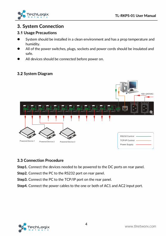
3. System Connection 3.1 Usage Precautions l System should be installed in a clean environment and has a prop temperature and
humidity. l All of the power switches, plugs, sockets and power cords should be insulated and
safe. l All devices should be connected before power on.
3.2 System Diagram
3.3 Connection Procedure Step1. Connect the devices needed to be powered to the DC ports on rear panel.
Step2. Connect the PC to the RS232 port on rear panel.
Step3. Connect the PC to the TCP/IP port on the rear panel.
Step4. Connect the power cables to the one or both of AC1 and AC2 input port.
AC100V 240V-
Tx Rx
RS232 TCP IP/
24V
+
AC100V 240V-
AC1 AC2
DC
12V
5V
+ ++ ++ ++ ++ ++ ++ ++ ++ ++ ++ ++
SELECT
24V
DC
12V
5V
SELECT
24V
DC
12V
5V
SELECT
24V
DC
12V
5V
SELECT
24V
DC
12V
5V
SELECT
24V
DC
12V
5V
SELECT
24V
DC
12V
5V
SELECT
24V
DC
12V
5V
SELECT
24V
DC
12V
5V
SELECT
24V
DC
12V
5V
SELECT
24V
DC
12V
5V
SELECT
24V
DC
12V
5V
SELECT
Powered Device 1 Powered Device 2 Powered Device 3
100~240VAC
RS232 Control
TCP IP Control/
Power Supply

5
TL-PKPS-01 User Manual
www.tlnetworx.com
4. System Operations 4.1 Front Panel Buttons l Switch on/off output channel:
Press the button 01~12 on front panel to switch on/off the corresponding output channel.
l Lock/unlock output channel:
Long-press the button 01~12 for 3 seconds or more on front panel to lock/unlock the assigned voltage of the corresponding channel, and then the corresponding LED will flash 3 times.
l Select the output voltage:
Press SELECT on corresponding output channel to select the output voltage as 5V, 12V or 24V.
Note: After switching the output voltage, the output channel will be turned off based on overvoltage protection control, and it need to be turned on again via the corresponding output channel switching button on front panel.
l Restore Factory Defaults:
On rear panel, simultaneously long-press SELECT on channel 01 and channel 02 for 3 seconds or more, the device will be restored to factory setting.
4.2 RS232 Control Connect a PC to the RS232 port on the rear panel, and then install the RS232 control software on the PC, the product can be controlled by sending RS232 commands via the RS232 control software.
4.2.1 Installation/uninstallation of RS232 Control Software
l Installation Copy the control software file to the computer connected with the product.
l Uninstallation Delete all the control software files in corresponding file path.
4.2.2 Basic Settings
Double-click the software icon to run this software.
Here we take the software CommWatch.exe as example. The icon is showed as below:
6
TL-RKPS-01 User Manual
www.tlnetworx.com
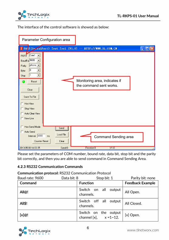
The interface of the control software is showed as below:
Please set the parameters of COM number, bound rate, data bit, stop bit and the parity bit correctly, and then you are able to send command in Command Sending Area.
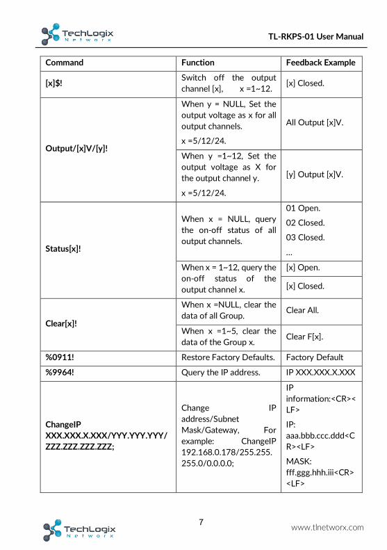
4.2.3 RS232 Communication Commands
Communication protocol: RS232 Communication Protocol Baud rate: 9600 Data bit: 8 Stop bit: 1 Parity bit: none
Command Function Feedback Example
All@! Switch on all output channels. All Open.
All$! Switch off all output channels. All Closed.
[x]@! Switch on the output channel [x], x =1~12. [x] Open.
Parameter Configuration area
Monitoring area, indicates if the command sent works.
Command Sending area
7
TL-RKPS-01 User Manual
www.tlnetworx.com
Command Function Feedback Example
[x]$! Switch off the output channel [x], x =1~12. [x] Closed.
Output/[x]V/[y]!
When y = NULL, Set the output voltage as x for all output channels.
x =5/12/24.
All Output [x]V.
When y =1~12, Set the output voltage as X for the output channel y.
x =5/12/24.
[y] Output [x]V.
Status[x]!
When x = NULL, query the on-off status of all output channels.
01 Open.
02 Closed.
03 Closed.
…
When x = 1~12, query the on-off status of the output channel x.
[x] Open.
[x] Closed.
Clear[x]!
When x =NULL, clear the data of all Group. Clear All.
When x =1~5, clear the data of the Group x. Clear F[x].
%0911! Restore Factory Defaults. Factory Default
%9964! Query the IP address. IP XXX.XXX.X.XXX
ChangeIP XXX.XXX.X.XXX/YYY.YYY.YYY/ZZZ.ZZZ.ZZZ.ZZZ;
Change IP address/Subnet Mask/Gateway, For example: ChangeIP 192.168.0.178/255.255.255.0/0.0.0.0;
IP information:<CR><LF>
IP: aaa.bbb.ccc.ddd<CR><LF>
MASK: fff.ggg.hhh.iii<CR><LF>

8
TL-RKPS-01 User Manual
www.tlnetworx.com
Command Function Feedback Example
GATEWAY: mmm.nnn.ooo.ppp<CR><LF>
Waiting process...<CR><LF>
<CR><LF>
IP Changed!<CR><LF>
%9975. Query the all status for all channels.
Out 01 02 03 04 05 06 07 08 09 10 11 12
State S S S S S S S S S S S S
Vm 12 12 12 12 12 12 12 12 12 12 12 12
Over N N N N N N N N N N N N
Lock N N N N N N N N N N N N
/*Name; Query the manufacturer. XXX
/*Type; Query the product model TL-RKPS-01
/^Version; Query the software version. V x. x. x
Baud[x]!
Set the baud rate as x. x = 1200, 2400,4800,9600,19200,38400, 57600,115200.
When x =NULL, the default baud rate is 9600.
Baud [x] not change.
Baud [y] change to [x].
Lock[x]! When x = NULL, lock all channels. Locking all channel.

9
TL-RKPS-01 User Manual
www.tlnetworx.com
Command Function Feedback Example
When x = 1~12, lock the channel x. Locking [x] channel.
Unlock[x]!
When x = NULL, unlock all channels. Locking all channel.
When x = 1~12, unlock the channel x. Locking [x] channel.
LockFrontPanel[x]!
When x=0, unlock the front panel.
Unlocking keyboard.
When x=1, lock the front panel. Locking keyboard.
Note:
l After sending the “Output/[x]V/[y].” to change the output voltage, the corresponding output channel will be switch off, the command “[x]@.” should be sent to switch on this output channel again.
l After sending the “LockKeyboard[x].” to lock the front panel, the device can be controlled via RS232 commands and web-based GUI.

10
TL-RKPS-01 User Manual
www.tlnetworx.com
4.3 Web-based GUI Control In addition to control the product via front panel button and RS232 communication software. This product can be controlled via web-based GUI. It allows users to interact with the product through graphical icons and visual indicators.
1. Connect a PC to the TCP/IP port on the rear panel, and set its network segment to the same as the default IP of the product (192.168.0.178, port No.: 4001).
2. Type 192.168.0.178 in your browser, it will enter the log-in interface shown as below:
Same network segment as the product.

11
TL-RKPS-01 User Manual
www.tlnetworx.com
4.3.1 Control Menu
Type user name: user and password: user (default setting) on the log-in interface, and then click Login to enter Control menu shown as below:
l Select the ON/OFF to switch on/off the output channel.
l Click the All On to switch on all output channels.

12
TL-RKPS-01 User Manual
www.tlnetworx.com
l Click the All Off to switch off all output channels.
4.3.2 Voltage Setting Menu
Click Voltage Setting on the top of page to enter voltage setting menu shown as below:
In this interface, you can select 5V, 12V, or 24V for each output channel. Locking the
individual ports will prevent changing of the voltages from the rear panel or the web
GUI until they are unlocked.
4.3.3 Network Menu
Click Network on the top of page to enter network setting menu shown as below:

13
TL-RKPS-01 User Manual
www.tlnetworx.com
In this interface, dynamic or static IP mode can be selected. Under static IP mode, IP address, subnet mask, and the gateway can be set. Make sure the IP addresses are unique to avoid any IP conflicts.
4.3.4 Password Menu
Click Password on the top of page to enter password menu shown as below:

14
TL-RKPS-01 User Manual
www.tlnetworx.com
In this interface, the password can be modified as needed, and the front panel can be
locked to prevent accidental powering on or off of devices.
4.3.5 Web-based GUI Update
Web-based GUI for the Scaler Switcher supports online update in http://192.168.0.178:100. Type the username and password (the same as the GUI log-in settings, modified password will be available only after rebooting) to log in the configuration interface. After that, click Administration at the source menu to get to Upload Program as shown below:
Select the desired update file and press Apply, it will start upgrading then.

15
TL-PKPS-01 User Manual
www.tlnetworx.com
5. Specification Input & Output
Input Port AC1 & AC2
Input Voltage 100~240VAC 50~60Hz
Output Port Total 12 DC port (2-Pin phoenix connectors)
Output Voltage 5V, 12V or 24V can be selectable. 12V is default
Output Voltage Range
5V: 4.75~5.25V
12V: 11.4~12.6V
24V: 22.8~25.2V
Maximum output power consumption of signal channel 5V:12W; 12V:15W; 24V:15W
Maximum output power consumption for single supply 110VAC:90W; 220VAC:180W
Maximum output power consumption for dual supply 180W
Control Part
Buttons Control Front Panel: 01~12, total 12 buttons.
Rear Panel: Total 12 TACT Switches, named SELECT.
RS232 Control RS232 port (3-Pin phoenix connector).
Baud rate support 1200, 2400, 4800, 9600 (default), 19200, 38400, 57600,115200.
Web-based GUI Control
TCP/IP port (RJ45).
Default IP: 192.168.0.178
Port No.: 4001
General
Temperature 0 ~ +50℃
Humidity 10% ~ 90%
Dimension (W*H*D) 437mm x 44mm x 357mm
Net Weight 4.2Kg

16
TL-PKPS-01 User Manual
www.tlnetworx.com
6. Panel Drawing
FIRMWARE
01 02 03 04 05 06
07 08 09 10 11 12
AC 2 AC 1
AC100V 240V-
Tx Rx
RS232 TCP IP/
24V
AC100V 240V-
AC1 AC2
DC
12V
5V
++
SELECT
24V
DC
12V
5V
SELECT
24V
DC
12V
5V
SELECT
24V
DC
12V
5V
SELECT
24V
DC
12V
5V
SELECT
24V
DC
12V
5V
SELECT
24V
DC
12V
5V
SELECT
24V
DC
12V
5V
SELECT
24V
DC
12V
5V
SELECT
24V
DC
12V
5V
SELECT
24V
DC
12V
5V
SELECT
24V
DC
12V
5V
SELECT
+ + + + + + + + + + + +
437 mm
357
mm
44 m
m

7. Troubleshooting & Maintenance Problems Causes Solutions
No output voltage
Power supply protect function
will start when over loaded. Please reduce loads.
After selecting output voltage, the output channel will switch off automatically.
Switch on the output channel via front panel button.
Fail or loose connection Make sure the connection is good.
AC1 or AC2 indicator doesn’t work or no respond to any operation
Fail connection of power cord. Make sure the power cord connection is good.
Cannot control the device by control device (e.g. a PC) through RS232 port
Wrong RS232 communication
parameters
Type in correct RS232
communication
parameters.
Fail or loose connection Make sure the connection is good.
Broken RS232 port Send it to authorized
dealer for checking.
Cannot control the
device by front panel
buttons while can
control it through
RS232 port
The front panel buttons are
broken
Send it to authorized
dealer for repairing.
Cannot control the device via Web-based GUI
The IP address of control PC and TCP/IP port are not on the same network segment
Modify control PC’s network segment to the same with the TCP/IP port.
The port No. are wrong. The correct port No. is 4001.
Fail or loose connection Make sure the connection is good.
Broken TCP/IP port Send it to authorized
dealer for checking.

Cannot control the
device by RS232 /
front panel
buttons/web-based
GUI.
The device has already been
broken.
Send it to authorized
dealer for repairing.
If your problem persists after following the above troubleshooting steps, seek further help from authorized dealer or our technical support.

8. After-sales Service If there appear some problems when running the device, please check and deal with the problems referenced in this user manual.
1) Product Limited Warranty: We warrant that our products will be free from defects in materials and workmanship for three years. Please see warranty page posted on www.tlnetworx.com for more info.
2) What the warranty does not cover: l Warranty expiration. l Factory applied serial number has been altered or removed from the product. l Damage, deterioration or malfunction caused by:
l Normal wear and tear l Use of supplies or parts not meeting our specifications l No certificate or invoice as the proof of warranty. l The product model showed on the warranty card does not match with the model of the product for repairing or had been altered. l Damage caused by force majeure. l Non-authorized service l Other causes which does not relate to a product defect
l Delivery, installation or labor charges for installation or setup of the product 3) Technical Support: Email to our after-sales department or make a call, please inform
us the following information about your cases. l Product version and name. l Detailed failure situations. l The formation of the cases.
Remarks: For any questions or problems, please try to get help from your local distributor.


![[UserManual] BIP7000_EN.pdf](https://img.pdfslide.net/doc/110x75/5870cf4e1a28ab31318b9a3a/usermanual-bip7000enpdf.jpg)