Embed Size (px)
Citation preview

State Road Strut
Whiskeag Stream
Bath, Maine
WIN 18392.00
1
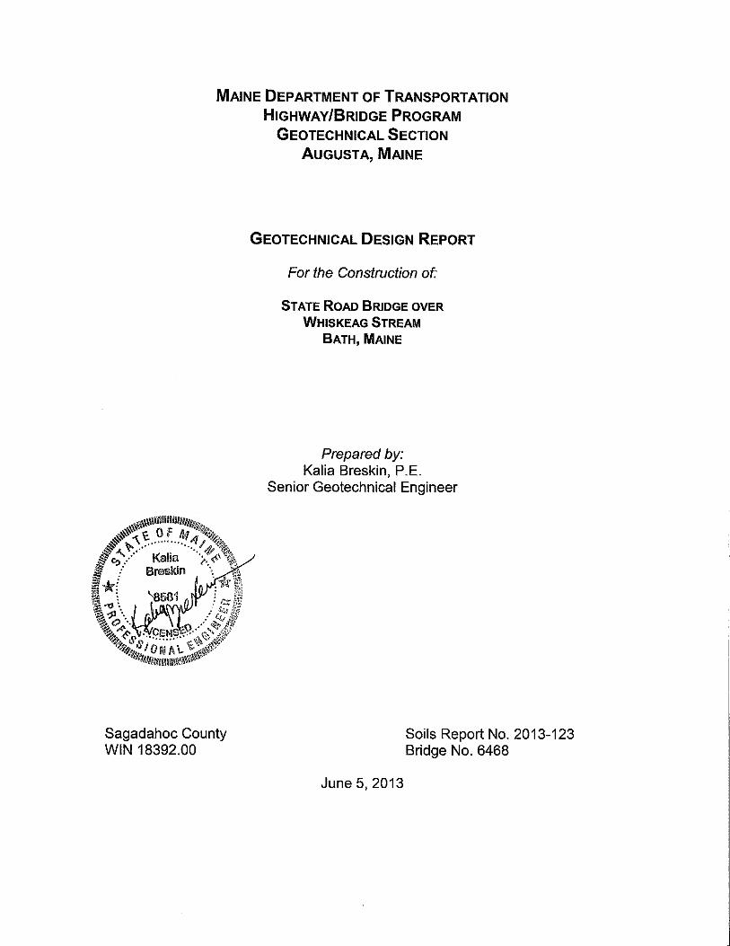
GEOTECHNICAL DESIGN SUMMARY
The purpose of this report is to present subsurface information and make geotechnical recommendations for the replacement of a box culvert which carries Whiskeag Stream under State Road at the Bath-West Bath Town Line, approximately 150 feet southwesterly of Congress Avenue in Bath. State Road is a Priority 4 Highway Corridor. The proposed replacement structure will be a 5-foot high, 10-foot span prefabricated 4-sided concrete box. No changes to the horizontal or vertical alignment of the roadway are proposed. The new structure will be 98 feet wide with two lanes, 14-feet from centerline to the face of guardrail. The project location is shown on Sheet 1, the Location Map. The following design and construction sections are discussed in detail in the attached report: Subsurface Investigation – One boring was drilled for this project on May 1, 2013 by the Maine DOT drill crew. The boring was approximately 20-feet from the culvert, and is shown on Sheet 2, the Geoplan and Interpretative Subsurface Cross Section. This boring was drilled using a hollow stem auger for a depth of 10 feet and cased wash boring to top of bedrock, with Standard Penetration Tests and split-spoon sampling. A rock core was taken using an NQ-2 inch core barrel. The boring was located in the field using a tape during the exploration program. The boring log and laboratory testing data are included in this report as Appendix A – Soils Data. Subsurface Conditions – Hot mix asphalt pavement was 7-inches thick in the boring. Subsurface conditions found in the boring included approximately 6-feet of fill soils overlying a stratum of clayey SILT over silty fine sand. This layer was interrupted by a one-foot thick layer or organic soils. Bedrock is of the Cape Elizabeth formation.
Fill – Fill soils consisted of brown, damp, gravelly fine to coarse sand with trace silt over a lower layer of brown, moist, loose, silty fine to medium sand. The total thickness of fill and gravel was approximately 6.5-feet. Corrected SPT N-values in the fill was 5 blows per foot, which indicates that the fill is loose, and was not well compacted during the original construction. Native Soils – The boring was at least 20-feet from the existing culvert, and soils more than 6.5-feet below ground surface would not have needed to be disturbed during construction of the existing structure. Precise stratification is not available from the boring log, as samples were taken only every 5-feet. The soils encountered below elevation 33.9 feet include a stratum of olive, wet, soft clayey silt with trace fine sand, underlain by olive-brown, wet, very loose silty fine to medium sand with little clay to elevation 26.4 feet where this soil becomes grey. A layer of peat or

State Road Strut
Whiskeag Stream
Bath, Maine
WIN 18392.00
2
organic soils was found from elevation 24.9 feet to elevation 23.9 feet, below which the silt sand continues to top of bedrock. It appears these lower soil strata may have been reworked material from earlier construction. Bedrock – Weathered rock was encountered from elevation 20.5 feet to elevation 19.4 feet. Solid bedrock had Rock Quality Designation of 88%, and was described as “white Feldspar and Quartz with trace amphibol, muscovite and purple (Granet). This is a high grade metamorphic rock. Once high angle 65o joint is at the top of the core, the remaining four joints are subhorizontal (0-20o) and irregular, only one has a slight staining (iron). The four lower segments are all over 8” long with the central one being almost 2’ long.” Groundwater – Groundwater was not observed in this boring, however the boring was not left open for any length of time. Groundwater levels surrounding the stream may fluctuate seasonally depending on precipitation. Existing Pavement Structure – The existing pavement structure observed in the boring had 7 inches of Hot Mix Asphalt. No difference was observed between the subbase gravel and the fill in a sample taken from the auger flights in the upper 4.5 feet of the boring. No laboratory testing was done on this soil.
Box Culvert Design and Construction – The 4-sided concrete box culvert with cast-in-place wingwalls and headwalls will be supplier-designed as specified in Special Provision 534, Precast Structural Concrete Arches, Box Culverts, by either the LFD or LRFD method. The loading specified for the structure shall be MS-22.5 (HS-25) for LFD method or modified HL-93 Strength I for the LRFD method, in which the HS-20 design truck wheel loads are increased by a factor of 1.25. The culvert will be constructed in general conformance with the MaineDOT Bridge Design Guide (BDG) Section 8, Buried Structures, and Special Provision 534. A copy of the Special Provision is attached to this report. The designer
may assume Soil Type 4 with φ=32o and γ=120 pcf for backfill soil properties. Soils at culvert subgrade were Grey, wet, loose silty sand with little clay, however bedrock was encountered at the elevation of the base of the culvert in the boring. Bedrock excavation may be required for construction of this structure. Crushed stone bedding between the base of this culvert and bedrock should be a minimum of 1-foot thick. The culvert soil envelope backfill shall consist of Standard Specification 703.19, Granular Borrow, Material for Underwater Backfill with a maximum particle size of 4 inches. Backfill shall be placed in lifts 6 to 8 inches thick and compacted to manufacturer’s specifications. In no case shall

State Road Strut
Whiskeag Stream
Bath, Maine
WIN 18392.00
3
the backfill soil be compacted to less than 92% of AASHTO T-180 maximum dry density. Culvert Wingwalls – Cast-in-place wingwalls will be built on all four corners of this box to reduce impacts in the stream. The wingwalls will be cast in place, and unable to rotate. Cast-in-place wingwalls should be designed using Ko conditions for a 32o soil, and any form of modular unit wingwall should be designed for active earth pressure Ka of 0.31. Box Culvert Bearing Resistance – Boring data indicates that bearing resistance will be determined by bedrock. A factored bearing resistance of 70 ksf is conservative for the high grade metamorphic rock at this site, and should be used for design. Scour and Riprap – Plain riprap inlet and outlet aprons shall be constructed to minimize future scour at this structure. Riprap conforming to Standard Specifications 610 and 703 shall be placed at as flat a slope as is practicable at this site. The new structure will be a minor span and the riprap apron shall be 3-feet thick as shown in Standard Detail 610(03). Seismic Design Considerations – Seismic analysis is not required for single span bridges regardless of seismic zone. Construction Considerations – If large boulders are encountered within the construction limits for this project, the boulders must be removed and the excavation backfilled with granular borrow or soils from the surrounding excavation, similar to soils at the same depth within the excavation. Very large stones and blast rock should not be used as part of the backfill for this construction. Native clay-silt soils could become difficult to work with when wet. Surface water should be controlled to allow the Contractor to maintain the integrity of excavated slopes during construction.
Attachments
Sheets Sheet 1 - Location Map Sheet 2 – GeoPlan and Cross Section Appendices Appendix - Boring Log and Laboratory Test Data

Map Scale 1:24000
The Maine Department of Transportation provides this publication for information only. Reliance upon this information is at user risk. It is subject to revisionand may be incomplete depending upon changing conditions. The Department assumes no liability if injuries or damages result from this information. Thismap is not intended to support emergency dispatch. Road names used on this map may not match official road names.
The Maine Department of Transportation provides this publication for information only. Reliance upon this information is at user risk. It is subject to revision and may be incomplete depending upon changingconditions. The Department assumes no liability if injuries or damages result from this information. This map is not intended to support emergency dispatch. Road names used on this map may not match officialroad names.


State Road Strut
Whiskeag Stream
Bath, Maine
WIN 18392.00
Appendix Boring Log
and Laboratory Test Data

0
5
10
15
20
25
S1
1D/A
2D
3D
R1
24/18
24/17
24/16
60/58
2.00 - 4.00
5.00 - 7.00
10.00 - 12.00
15.00 - 17.00
21.00 - 26.00
Off Flights
2/2/2/2
1/1/1/WOH
WOH/WOH/WOH/3
RQD = 88%
4
2
---
5
3
SSA
4
5
6
7
10
8
15
32
33
58
NQ-2
39.82
35.90
33.90
26.40
24.90
23.90
20.50
19.40
7" PAVEMENT.0.58
Brown, damp, gravelly, fine to coarse SAND, trace silt, (Fill).
4.50
1D (5.0-6.5 ft) Brown, moist, loose, silty fine to medium SAND (Fill).
6.501D/A (6.5-7.0 ft) Olive, wet, loose, SAND, some clay, some silt, trace
gravel.
Olive-brown, wet, very soft, silty CLAY, little sand, trace gravel.
14.00
Grey, wet, very loose, silty, fine to medium SAND, little clay.15.50
Organics, (PEAT).
16.50Grey, wet, very loose, silty, fine to medium SAND, little clay.
19.90Weathered ROCK. Roller Coned ahead to 21.0 ft bgs.
21.00Top of Bedrock at Elev. 19.4 ft.
R1:Bedrock: White Feldspar and Quartz with trace amphibol,
muscovite and purple (Garnet?) This is a high grade metamorphic
rock. One high angle 65o joint is at the top of the core, the remaining
four joints are subhorizontal (0-20o) and irregular, only one has slight
staining (iron). The four lower segments are all over 8" long with a
central one being almost 2' long.
R1:Core Times (min:sec)
G#261740
A-4, CL-ML
WC=15.9%
G#261741
A-4, CL
WC=26.9%
Maine Department of Transportation Project: State Road Strut Boring No.: SB-BATH-101
Soil/Rock Exploration LogLocation: Bath-West Bath, Maine
US CUSTOMARY UNITS WIN: 18392.00
Driller: MaineDOT Elevation (ft.) 40.4 Auger ID/OD: 5" Solid Stem
Operator: Enos/Giles/Daggett Datum: NAVD88 Sampler: Standard Split Spoon
Logged By: B. Wilder Rig Type: CME 45C Hammer Wt./Fall: 140#/30"
Date Start/Finish: 5/1/2013; 08:00-12:00 Drilling Method: Cased Wash Boring Core Barrel: NQ-2"
Boring Location: 344+77.4, 9.5 ft Lt. Casing ID/OD: NW Water Level*: None Observed
Hammer Efficiency Factor: 0.756 Hammer Type: Automatic Hydraulic Rope & Cathead
Definitions: R = Rock Core Sample Su = Insitu Field Vane Shear Strength (psf) Su(lab) = Lab Vane Shear Strength (psf)
D = Split Spoon Sample SSA = Solid Stem Auger Tv = Pocket Torvane Shear Strength (psf) WC = water content, percent
MD = Unsuccessful Split Spoon Sample attempt HSA = Hollow Stem Auger qp = Unconfined Compressive Strength (ksf) LL = Liquid Limit
U = Thin Wall Tube Sample RC = Roller Cone N-uncorrected = Raw field SPT N-value PL = Plastic Limit
MU = Unsuccessful Thin Wall Tube Sample attempt WOH = weight of 140lb. hammer Hammer Efficiency Factor = Annual Calibration Value PI = Plasticity Index
V = Insitu Vane Shear Test, PP = Pocket Penetrometer WOR/C = weight of rods or casing N60 = SPT N-uncorrected corrected for hammer efficiency G = Grain Size Analysis
MV = Unsuccessful Insitu Vane Shear Test attempt WO1P = Weight of one person N60 = (Hammer Efficiency Factor/60%)*N-uncorrected C = Consolidation Test
Remarks:
Stratification lines represent approximate boundaries between soil types; transitions may be gradual.
* Water level readings have been made at times and under conditions stated. Groundwater fluctuations may occur due to conditions otherthan those present at the time measurements were made. Boring No.: SB-BATH-101
Depth (ft.)
Sample No.
Sample Information
Pen./Rec. (in.)
Sample Depth
(ft.)
Blows (/6 in.)
Shear
Strength
(psf)
or RQD (%)
N-uncorrected
N60
Casing
Blows
Elevation
(ft.)
Graphic Log
Visual Description and Remarks
LaboratoryTesting Results/AASHTO and
Unified Class.
Page 1 of 2

25
30
35
40
45
50
14.40
21.0-22.0 ft (2:30)
22.0-23.0 ft (2:15)
23.0-24.0 ft (2:15)
24.0-25.0 ft (2:05)
25.0-26.0 ft (2:15) 97% Recovery26.00
Bottom of Exploration at 26.00 feet below ground surface.
Maine Department of Transportation Project: State Road Strut Boring No.: SB-BATH-101
Soil/Rock Exploration LogLocation: Bath-West Bath, Maine
US CUSTOMARY UNITS WIN: 18392.00
Driller: MaineDOT Elevation (ft.) 40.4 Auger ID/OD: 5" Solid Stem
Operator: Enos/Giles/Daggett Datum: NAVD88 Sampler: Standard Split Spoon
Logged By: B. Wilder Rig Type: CME 45C Hammer Wt./Fall: 140#/30"
Date Start/Finish: 5/1/2013; 08:00-12:00 Drilling Method: Cased Wash Boring Core Barrel: NQ-2"
Boring Location: 344+77.4, 9.5 ft Lt. Casing ID/OD: NW Water Level*: None Observed
Hammer Efficiency Factor: 0.756 Hammer Type: Automatic Hydraulic Rope & Cathead
Definitions: R = Rock Core Sample Su = Insitu Field Vane Shear Strength (psf) Su(lab) = Lab Vane Shear Strength (psf)
D = Split Spoon Sample SSA = Solid Stem Auger Tv = Pocket Torvane Shear Strength (psf) WC = water content, percent
MD = Unsuccessful Split Spoon Sample attempt HSA = Hollow Stem Auger qp = Unconfined Compressive Strength (ksf) LL = Liquid Limit
U = Thin Wall Tube Sample RC = Roller Cone N-uncorrected = Raw field SPT N-value PL = Plastic Limit
MU = Unsuccessful Thin Wall Tube Sample attempt WOH = weight of 140lb. hammer Hammer Efficiency Factor = Annual Calibration Value PI = Plasticity Index
V = Insitu Vane Shear Test, PP = Pocket Penetrometer WOR/C = weight of rods or casing N60 = SPT N-uncorrected corrected for hammer efficiency G = Grain Size Analysis
MV = Unsuccessful Insitu Vane Shear Test attempt WO1P = Weight of one person N60 = (Hammer Efficiency Factor/60%)*N-uncorrected C = Consolidation Test
Remarks:
Stratification lines represent approximate boundaries between soil types; transitions may be gradual.
* Water level readings have been made at times and under conditions stated. Groundwater fluctuations may occur due to conditions otherthan those present at the time measurements were made. Boring No.: SB-BATH-101
Depth (ft.)
Sample No.
Sample Information
Pen./Rec. (in.)
Sample Depth
(ft.)
Blows (/6 in.)
Shear
Strength
(psf)
or RQD (%)
N-uncorrected
N60
Casing
Blows
Elevation
(ft.)
Graphic Log
Visual Description and Remarks
LaboratoryTesting Results/AASHTO and
Unified Class.
Page 2 of 2

3" 2" 1-1/2" 1" 3/4" 1/2" 3/8" 1/4" #4 #8 #10 #16 #20 #40 #60 #100 #200 0.05 0.03 0.010 0.005 0.001
76.2 50.8 38.1 25.4 19.05 12.7 9.53 6.35 4.75 2.36 2.00 1.18 0.85 0.426 0.25 0.15 0.075 0.05 0.03 0.005
GRAVEL SAND SILT
SIEVE ANALYSISUS Standard Sieve Numbers
HYDROMETER ANALYSISGrain Diameter, mm
State of Maine Department of TransportationGRAIN SIZE DISTRIBUTION CURVE
100 10 1 0.1 0.01 0.001
Grain Diameter, mm
0
10
20
30
40
50
60
70
80
90
100
Percent Finer by W
eight
100
90
80
70
60
50
40
30
20
10
0
Percent Retained by W
eight
CLAY
SHEET NO.
UNIFIED CLASSIFICATION
SAND, some clay, some silt, trace gravel.
Silty CLAY, little sand, trace gravel.
15.9
26.9
NPSB-BATH-101/1D/A
SB-BATH-101/2D
6.5-7.0
10.0-12.0
Depth, ftBoring/Sample No. Description W, % LL PL PI
����
����
����
����
��������
SHEET 1
West Bath
018392.00
WHITE, TERRY A 6/3/2013
WIN
Town
Reported by/Date
9.5 LT
9.5 LT
Offset, ft
344+77.4
344+77.4
Station

Station Offset Depth Reference G.S.D.C. W.C. L.L. P.I.
(Feet) (Feet) (Feet) Number Sheet % Unified AASHTO Frost
344+77.4 9.5 Lt. 6.5-7.0 261740 1 15.9 CL-ML A-4 IV
344+77.4 9.5 Lt. 10.0-12.0 261741 1 26.9 CL A-4 IV
Classification of these soil samples is in accordance with AASHTO Classification System M-145-40. This classification
is followed by the "Frost Susceptibility Rating" from zero (non-frost susceptible) to Class IV (highly frost susceptible).
The "Frost Susceptibility Rating" is based upon the MaineDOT and Corps of Engineers Classification Systems.
GSDC = Grain Size Distribution Curve as determined by AASHTO T 88-93 (1996) and/or ASTM D 422-63 (Reapproved 1998)
WC = water content as determined by AASHTO T 265-93 and/or ASTM D 2216-98
LL = Liquid limit as determined by AASHTO T 89-96 and/or ASTM D 4318-98
PI = Plasticity Index as determined by AASHTO 90-96 and/or ASTM D4318-98
NP = Non Plastic
Identification Number
SB-BATH-101, 1D/A
Work Number: 18392.00
SB-BATH-101, 2D
Classification
State of Maine - Department of Transportation
Laboratory Testing Summary Sheet
Town(s): West Bath-BathBoring & Sample
1 of 1

Reference No.
261740
1 2 D e s e r t R d , F r e e p o r t M a i n e DO T T E S T I NG L ABORA T OR I E S 2 1 9 H o g a n R d , B a n g o r
Sample Description
GEOTECHNICAL (DISTURBED)
Sampler: WILDER, BRUCE H
Location: ROADWAY
Sampled
5/1/2013
Received
5/14/2013
Miscellaneous Tests
Comments:
Station: 344+77.4 Offset, ft: 9.5 LT Dbfg, ft: 6.5-7.0
Boring No./Sample No.
SB-BATH-101/1D/A
Liquid Limit @ 25 blows(T 89), %
Plastic Limit (T 90), %
Plasticity Index (T 90), %
NP
Specific Gravity, Corrected to 20°C (T 100)
2.69
Loss on Ignition (T 267)
Sample Type: GEOTECHNICAL
Depth
taken in
tube, ft tons/ft² tons/ft²
3 In.
tons/ft² tons/ft²
6 In. Water
Content,
%
Description of Material Sampled at the
Various Tube Depths
Vane Shear Test on Shelby Tubes (Maine DOT)
Direct Shear (T 236)
Shear Angle, °
Normal Stress, psi
Initial Water Content, %
Wet Density, lbs/ft³
Dry Density, lbs/ft³
Specimen Thickness, in
Water Content (T 265), %
15.9
Loss, % H2O, %
Paper Copy: Lab File; Project File; Geotech File
Reported by: FOGG, BRIAN Date Reported: 5/31/2013
S A M P L E I N F O R M A T I O N
A U T H O R I Z A T I O N A N D D I S T R I B U T I O N
T E S T R E S U L T S
U. Shear Remold U. Shear Remold
Sieve Analysis (T 88)
3 in. [75.0 mm] 100.0
⅜ in. [9.5 mm] 95.3
¾ in. [19.0 mm] 95.7
½ in. [12.5 mm] 95.7
SIEVE SIZEU.S. [SI]
% Passing
¼ in. [6.3 mm] 94.9
No. 4 [4.75 mm] 94.4
No. 10 [2.00 mm] 93.1
1 in. [25.0 mm] 100.0
No. 20 [0.850 mm]
No. 40 [0.425 mm] 85.0
No. 200 [0.075 mm] 43.1
No. 60 [0.250 mm]
No. 100 [0.150 mm]
Wash Method
GEOTECHNICAL TEST REPORT
Central Laboratory
Consolidation (T 216)
Trimmings, Water Content, %
Initial FinalVoid
Ratio
%
Strain
Water Content, %
Dry Density, lbs/ft³
Void Ratio
Saturation, %
Pmin
Pp
Pmax
Cc/C'c
WIN/Town 018392.00 - WEST BATH
[0.0315 mm] 38.6
[0.0202 mm] 36.2
[0.0118 mm] 33.8
[0.0085 mm] 29.0
[0.0065 mm] 26.6
[0.0031 mm] 24.2
[0.0014 mm] 19.4

Reference No.
261741
1 2 D e s e r t R d , F r e e p o r t M a i n e DO T T E S T I NG L ABORA T OR I E S 2 1 9 H o g a n R d , B a n g o r
Sample Description
GEOTECHNICAL (DISTURBED)
Sampler: WILDER, BRUCE H
Location: ROADWAY
Sampled
5/1/2013
Received
5/14/2013
Miscellaneous Tests
Comments:
Station: 344+77.4 Offset, ft: 9.5 LT Dbfg, ft: 10.0-12.0
Boring No./Sample No.
SB-BATH-101/2D
Liquid Limit @ 25 blows(T 89), %
Plastic Limit (T 90), %
Plasticity Index (T 90), %
Specific Gravity, Corrected to 20°C (T 100)
2.72
Loss on Ignition (T 267)
Sample Type: GEOTECHNICAL
Depth
taken in
tube, ft tons/ft² tons/ft²
3 In.
tons/ft² tons/ft²
6 In. Water
Content,
%
Description of Material Sampled at the
Various Tube Depths
Vane Shear Test on Shelby Tubes (Maine DOT)
Direct Shear (T 236)
Shear Angle, °
Normal Stress, psi
Initial Water Content, %
Wet Density, lbs/ft³
Dry Density, lbs/ft³
Specimen Thickness, in
Water Content (T 265), %
26.9
Loss, % H2O, %
Paper Copy: Lab File; Project File; Geotech File
Reported by: FOGG, BRIAN Date Reported: 5/24/2013
S A M P L E I N F O R M A T I O N
A U T H O R I Z A T I O N A N D D I S T R I B U T I O N
T E S T R E S U L T S
U. Shear Remold U. Shear Remold
Sieve Analysis (T 88)
3 in. [75.0 mm]
⅜ in. [9.5 mm] 99.0
¾ in. [19.0 mm] 100.0
½ in. [12.5 mm] 99.0
SIEVE SIZEU.S. [SI]
% Passing
¼ in. [6.3 mm] 99.0
No. 4 [4.75 mm] 98.9
No. 10 [2.00 mm] 98.6
1 in. [25.0 mm]
No. 20 [0.850 mm]
No. 40 [0.425 mm] 95.9
No. 200 [0.075 mm] 82.2
No. 60 [0.250 mm]
No. 100 [0.150 mm]
Wash Method
GEOTECHNICAL TEST REPORT
Central Laboratory
Consolidation (T 216)
Trimmings, Water Content, %
Initial FinalVoid
Ratio
%
Strain
Water Content, %
Dry Density, lbs/ft³
Void Ratio
Saturation, %
Pmin
Pp
Pmax
Cc/C'c
WIN/Town 018392.00 - WEST BATH
[0.0269 mm] 77.6
[0.0175 mm] 72.1
[0.0111 mm] 66.6
[0.0081 mm] 60.9
[0.0058 mm] 55.4
[0.0030 mm] 47.1
[0.0013 mm] 36.0