Embed Size (px)
DESCRIPTION
Yamaha 135 Manual
Citation preview
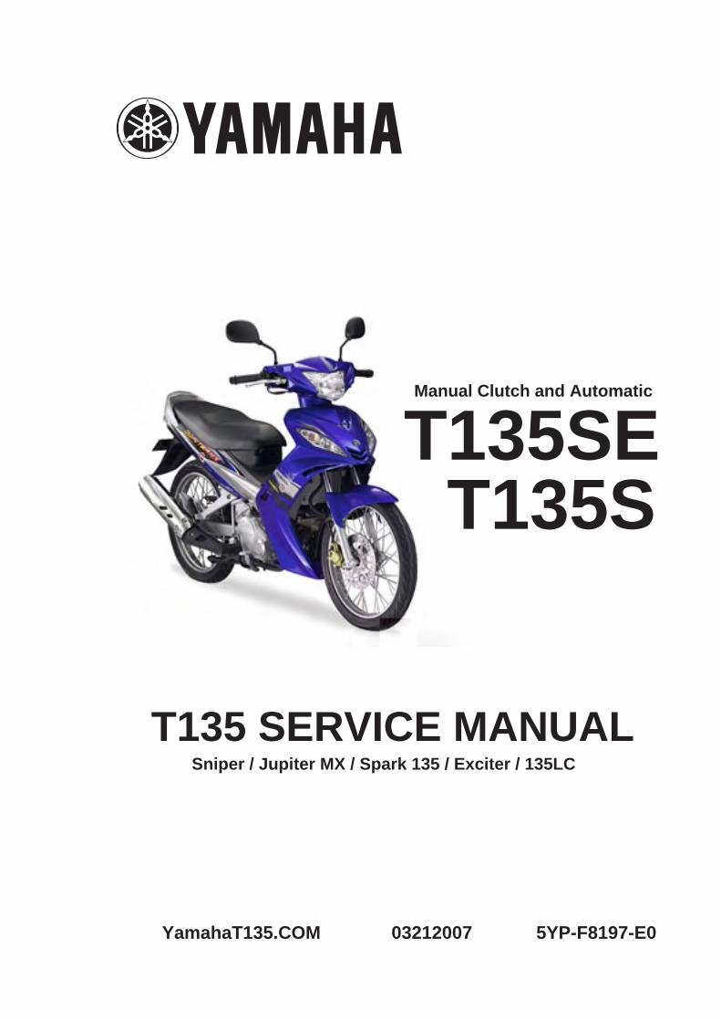
T135 SERVICE MANUAL
5YP-F8197-E0
5YP-F8197-E0_ cover 05.5.9 17:35 Page 1
T135SET135S
Sniper / Jupiter MX / Spark 135 / Exciter / 135LC
YamahaT135.COM 03212007
Manual Clutch and Automatic

Yamaha T135 Service Manual
YamahaT135.COM
T135SE/T135SSERVICE MANUAL
©2005 by Yamaha Motor Co., Ltd.First edition, April, 2005
All rights reserved.Any reproduction or unauthorized use
without the written permission ofYamaha Motor Co., Ltd.is expressly prohibited.
EAS00000
5YP-F8197-E0_1_2 05.6.27 19:47 Page A
Yamaha T135 Service Manual
YamahaT135.COM
EAS00002
NOTICE
This manual was produced by the Yamaha Motor Company, Ltd. primarily for use by Yamaha dealersand their qualified mechanics. It is not possible to include all the knowledge of a mechanic in one man-ual. Therefore, anyone who uses this book to perform maintenance and repairs on Yamaha vehiclesshould have a basic understanding of mechanics and the techniques to repair these types of vehicles.Repair and maintenance work attempted by anyone without this knowledge is likely to render the vehi-cle unsafe and unfit for use.
Yamaha Motor Company, Ltd. is continually striving to improve all of its models. Modifications and sig-nificant changes in specifications or procedures will be forwarded to all authorized Yamaha dealers andwill appear in future editions of this manual where applicable.
NOTE:
Designs and specifications are subject to change without notice.
EAS00004
IMPORTANT MANUAL INFORMATION
Particularly important information is distinguished in this manual by the following.
Q The Safety Alert Symbol means ATTENTION! BECOME ALERT! YOUR SAFETY ISINVOLVED!
w Failure to follow WARNING instructions could result in severe injury or death to thevehicle operator, a bystander or a person checking or repairing the vehicle.
cC A CAUTION indicates special precautions that must be taken to avoid damage tothe vehicle.
NOTE: A NOTE provides key information to make procedures easier or clearer.
5YP-F8197-E0_1_2 05.6.27 19:47 Page B
Yamaha T135 Service Manual
YamahaT135.COM
EASF0001
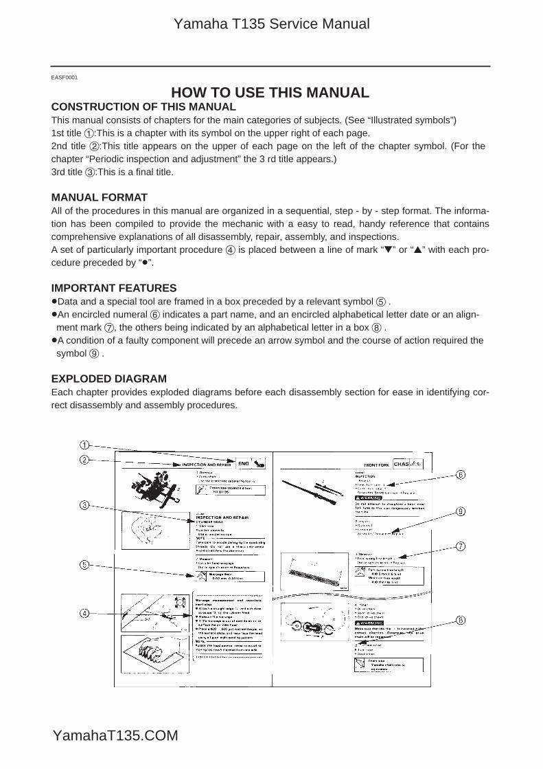
HOW TO USE THIS MANUALCONSTRUCTION OF THIS MANUALThis manual consists of chapters for the main categories of subjects. (See “Illustrated symbols”)1st title 1:This is a chapter with its symbol on the upper right of each page.2nd title 2:This title appears on the upper of each page on the left of the chapter symbol. (For thechapter “Periodic inspection and adjustment” the 3 rd title appears.)3rd title 3:This is a final title.
MANUAL FORMATAll of the procedures in this manual are organized in a sequential, step - by - step format. The informa-tion has been compiled to provide the mechanic with a easy to read, handy reference that containscomprehensive explanations of all disassembly, repair, assembly, and inspections.A set of particularly important procedure 4 is placed between a line of mark “” or “” with each pro-cedure preceded by “8”.
IMPORTANT FEATURES8Data and a special tool are framed in a box preceded by a relevant symbol 5 .8An encircled numeral 6 indicates a part name, and an encircled alphabetical letter date or an align-ment mark 7, the others being indicated by an alphabetical letter in a box 8 .8A condition of a faulty component will precede an arrow symbol and the course of action required thesymbol 9 .
EXPLODED DIAGRAMEach chapter provides exploded diagrams before each disassembly section for ease in identifying cor-rect disassembly and assembly procedures.
5YP-F8197-E0_1_2 05.6.27 19:47 Page C
Yamaha T135 Service Manual
YamahaT135.COM

5YP-F8197-E0_1_2 05.6.27 19:47 Page D
Yamaha T135 Service Manual
YamahaT135.COM
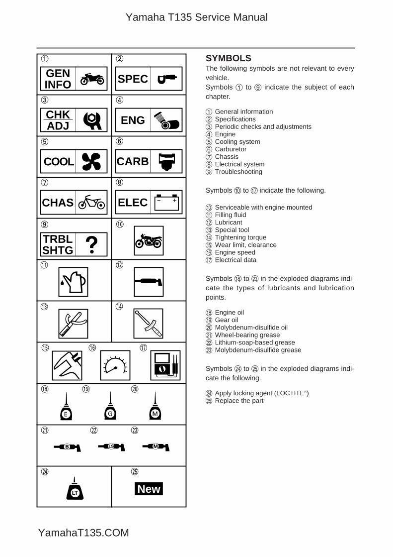
SYMBOLSThe following symbols are not relevant to everyvehicle.Symbols 1 to 9 indicate the subject of eachchapter.
1 General information2 Specifications3 Periodic checks and adjustments4 Engine5 Cooling system6 Carburetor7 Chassis8 Electrical system9 Troubleshooting
Symbols 0 to u indicate the following.
0 Serviceable with engine mountedq Filling fluidw Lubricante Special toolr Tightening torquet Wear limit, clearancey Engine speedu Electrical data
Symbols i to d in the exploded diagrams indi-cate the types of lubricants and lubricationpoints.
i Engine oilo Gear oilp Molybdenum-disulfide oila Wheel-bearing greases Lithium-soap-based greased Molybdenum-disulfide grease
Symbols f to g in the exploded diagrams indi-cate the following.
f Apply locking agent (LOCTITE®)g Replace the part
1 2
3 4
y u
i o p
a s d
f g
GENINFO SPEC
CHKADJ ENG
LT New
COOL
t
re
wq
09
TRBLSHTG
8
ELEC
7
CHAS
6
CARB
5
5YP-F8197-E0_1_2 05.6.27 19:47 Page E
Yamaha T135 Service Manual
YamahaT135.COM
5YP-F8197-E0_1_2 05.6.27 19:47 Page F
Yamaha T135 Service Manual
YamahaT135.COM
SPECIFICATIONS
TROUBLESHOOTING
ELECTRICAL SYSTEM
CHASSIS
ENGINE
PERIODIC CHECKS AND ADJUSTMENTS
GENERAL INFORMATION GENINFO
TRBLSHTG
ELEC
CHAS
ENG
CHKADJ
SPEC
TABLE OF CONTENTS
4
7
8
9
3
2
1
COOLING SYSTEMCOOL 5
CARBURETORCARB 6
EAS00011
5YP-F8197-E0_1_2 05.6.27 19:47 Page G
Yamaha T135 Service Manual
YamahaT135.COM

5YP-F8197-E0_1_2 05.6.27 19:47 Page H
Yamaha T135 Service Manual
YamahaT135.COM
GENINFO
CHAPTER 1GENERAL INFORMATION
VEHICLE IDENTIFICATION ...................................................................................1-1VEHICLE IDENTIFICATION NUMBER .............................................................1-1ENGINE SERIAL NUMBER...............................................................................1-1
IMPORTANT INFORMATION .................................................................................1-2PREPARATION FOR REMOVAL AND DISASSEMBLY ...................................1-2REPLACEMENT PARTS ..................................................................................1-2GASKETS, OIL SEALS AND O-RINGS ............................................................1-2LOCK WASHERS/PLATES AND COTTER PINS .............................................1-3BEARINGS AND OIL SEALS ............................................................................1-3CIRCLIPS .........................................................................................................1-3
CHECKING THE CONNECTIONS .........................................................................1-4
SPECIAL TOOLS ...................................................................................................1-5
5YP-F8197-E0_1_2 05.6.27 19:47 Page 1A
Yamaha T135 Service Manual
YamahaT135.COM
GENINFO
5YP-F8197-E0_1_2 05.6.27 19:47 Page 1B
Yamaha T135 Service Manual
YamahaT135.COM
1-1
GENINFOVEHICLE IDENTIFICATION
EAS00014
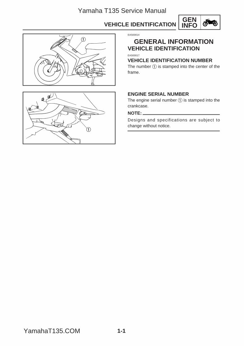
GENERAL INFORMATIONVEHICLE IDENTIFICATIONEAS00017
VEHICLE IDENTIFICATION NUMBERThe number 1 is stamped into the center of theframe.
ENGINE SERIAL NUMBERThe engine serial number 1 is stamped into thecrankcase.
NOTE:
Designs and specifications are subject tochange without notice.
1
1
5YP-F8197-E0_1_2 05.6.27 19:47 Page 1
Yamaha T135 Service Manual
YamahaT135.COM
GENINFOIMPORTANT INFORMATION
EAS00020
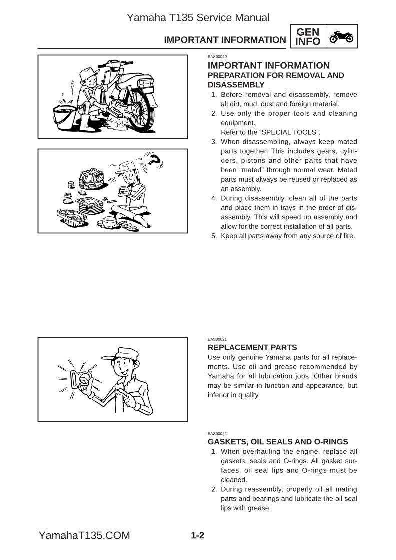
IMPORTANT INFORMATIONPREPARATION FOR REMOVAL ANDDISASSEMBLY1. Before removal and disassembly, remove
all dirt, mud, dust and foreign material.2. Use only the proper tools and cleaning
equipment.Refer to the “SPECIAL TOOLS”.
3. When disassembling, always keep matedparts together. This includes gears, cylin-ders, pistons and other parts that havebeen “mated” through normal wear. Matedparts must always be reused or replaced asan assembly.
4. During disassembly, clean all of the partsand place them in trays in the order of dis-assembly. This will speed up assembly andallow for the correct installation of all parts.
5. Keep all parts away from any source of fire.
1-2
EAS00021
REPLACEMENT PARTSUse only genuine Yamaha parts for all replace-ments. Use oil and grease recommended byYamaha for all lubrication jobs. Other brandsmay be similar in function and appearance, butinferior in quality.
EAS00022
GASKETS, OIL SEALS AND O-RINGS1. When overhauling the engine, replace all
gaskets, seals and O-rings. All gasket sur-faces, oil seal lips and O-rings must becleaned.
2. During reassembly, properly oil all matingparts and bearings and lubricate the oil seallips with grease.
5YP-F8197-E0_1_2 05.6.27 19:47 Page 2
Yamaha T135 Service Manual
YamahaT135.COM
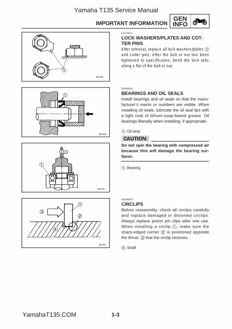
EAS00024
BEARINGS AND OIL SEALSInstall bearings and oil seals so that the manu-facturer’s marks or numbers are visible. Wheninstalling oil seals, lubricate the oil seal lips witha light coat of lithium-soap-based grease. Oilbearings liberally when installing, if appropriate.
1 Oil seal
cCDo not spin the bearing with compressed airbecause this will damage the bearing sur-faces.
1 Bearing
EAS00025
CIRCLIPSBefore reassembly, check all circlips carefullyand replace damaged or distorted circlips.Always replace piston pin clips after one use.When installing a circlip 1 , make sure thesharp-edged corner 2 is positioned oppositethe thrust 3 that the circlip receives.
4 Shaft
GENINFOIMPORTANT INFORMATION
1
300-000
300-003
1
300-002
1
300-001
3
4
1
2
EAS00023
LOCK WASHERS/PLATES AND COT-TER PINSAfter removal, replace all lock washers/plates 1and cotter pins. After the bolt or nut has beentightened to specification, bend the lock tabsalong a flat of the bolt or nut.
1-3
5YP-F8197-E0_1_2 05.6.27 19:47 Page 3
Yamaha T135 Service Manual
YamahaT135.COM
GENINFOCHECKING THE CONNECTIONS
1
EAS00026
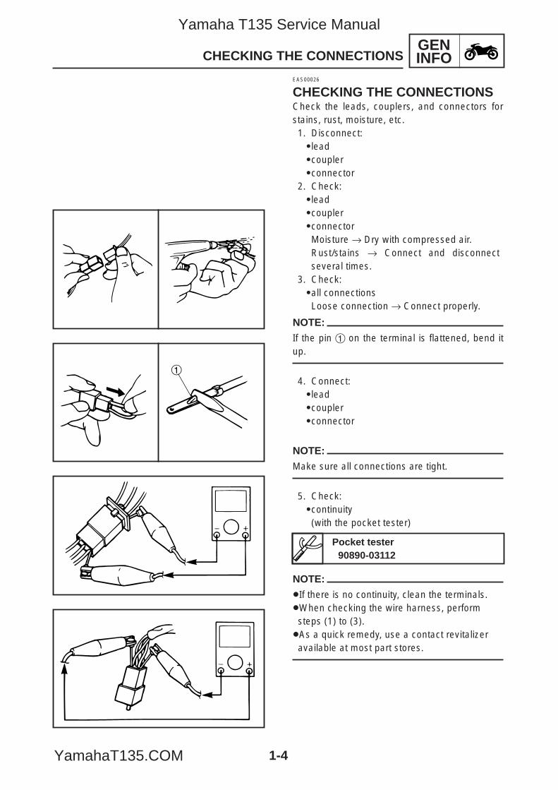
CHECKING THE CONNECTIONSCheck the leads, couplers, and connectors forstains, rust, moisture, etc.1. Disconnect:9lead9coupler9connector
2. Check:9lead9coupler9connectorMoisture → Dry with compressed air.Rust/stains → Connect and disconnectseveral times.
3. Check:9all connectionsLoose connection → Connect properly.
NOTE:
If the pin 1 on the terminal is flattened, bend itup.
4. Connect:9lead9coupler9connector
NOTE:
Make sure all connections are tight.
5. Check:9continuity(with the pocket tester)
NOTE:
8If there is no continuity, clean the terminals.8When checking the wire harness, performsteps (1) to (3).8As a quick remedy, use a contact revitalizeravailable at most part stores.
1-4
Pocket tester90890-03112
5YP-F8197-E0_1_2 05.6.27 19:47 Page 4
Yamaha T135 Service Manual
YamahaT135.COM
GENINFOSPECIAL TOOLS
1-5
EAS00027
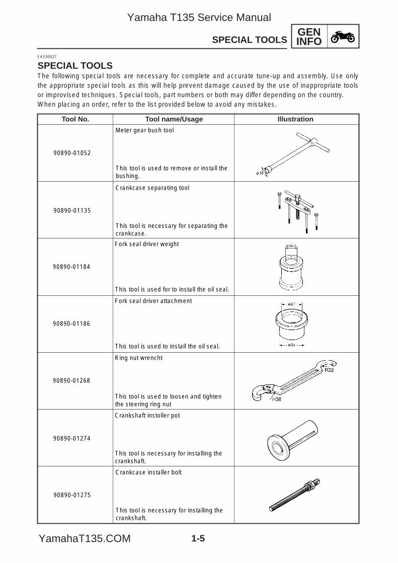
SPECIAL TOOLSThe following special tools are necessary for complete and accurate tune-up and assembly. Use onlythe appropriate special tools as this will help prevent damage caused by the use of inappropriate toolsor improvised techniques. Special tools, part numbers or both may differ depending on the country.When placing an order, refer to the list provided below to avoid any mistakes.
90890-01135
Crankcase separating tool
This tool is necessary for separating the crankcase.
90890-01184
Fork seal driver weight
This tool is used for to install the oil seal.
90890-01186
Fork seal driver attachment
This tool is used to install the oil seal.
90890-01268
Ring nut wrencht
This tool is used to loosen and tighten the steering ring nut
Crankshaft instoller pot
This tool is necessary for installing thecrankshaft.
90890-01274
90890-01275
Crankcase installer bolt
This tool is necessary for installing the crankshaft.
Tool No. Tool name/Usage Illustration
90890-01052
Meter gear bush tool
This tool is used to remove or install thebushing.
5YP-F8197-E0_1_2 05.6.27 19:47 Page 5
Yamaha T135 Service Manual
YamahaT135.COM
GENINFOSPECIAL TOOLS
1-6
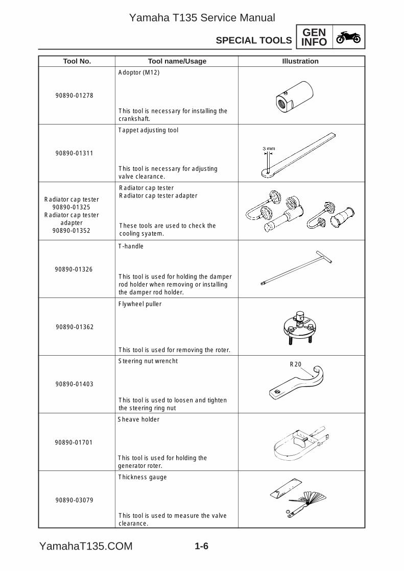
90890-01278
Adoptor (M12)
This tool is necessary for installing the crankshaft.
90890-01311
Tappet adjusting tool
This tool is necessary for adjustingvalve clearance.
Radiator cap tester90890-01325
Radiator cap testeradapter
90890-01352
Radiator cap testerRadiator cap tester adapter
These tools are used to check the cooling syatem.
T-handle
This tool is used for holding the damperrod holder when removing or installingthe damper rod holder.
90890-01326
Flywheel puller
This tool is used for removing the roter.
90890-01362
90890-01403
Steering nut wrencht
This tool is used to loosen and tighten the steering ring nut
R20
90890-01701
Sheave holder
This tool is used for holding thegenerator roter.
90890-03079
Thickness gauge
This tool is used to measure the valveclearance.
Tool No. Tool name/Usage Illustration
5YP-F8197-E0_1_2 05.6.27 19:47 Page 6
Yamaha T135 Service Manual
YamahaT135.COM
GENINFOSPECIAL TOOLS
1-7
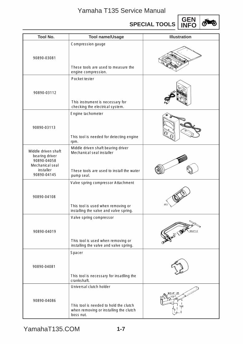
90890-03081
Compression gauge
These tools are used to measure theengine compression.
90890-03112
Pocket tester
This instrument is necessary forchecking the electrical system.
90890-03113
Engine tachometer
This tool is needed for detecting enginerpm.
Middle driven shaftbearing driver90890-04058
Mechanical sealinstaller
90890-04145
Middle driven shaft bearing driverMechanical seal installer
These tools are used to install the waterpump seal.
Valve spring compressor Attachment
This tool is used when removing orinstalling the valve and valve spring.
90890-04108
Ø22
Valve spring compressor
This tool is used when removing orinstalling the valve and valve spring.
90890-04019fl31
M6xP1.0
90890-04081
Spacer
This tool is necessary for insatlling thecrankshaft.
90890-04086
Universal clutch holder
This tool is needed to hold the clutchwhen removing or installing the clutchboss nut.
Tool No. Tool name/Usage Illustration
5YP-F8197-E0_1_2 05.6.27 19:47 Page 7
Yamaha T135 Service Manual
YamahaT135.COM
GENINFOSPECIAL TOOLS
1-8
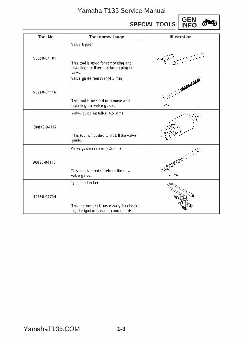
90890-04101
Valve lapper
This tool is used for removeing andinstalling the lifter and for lapping the valve.
90890-04116
Valve guide remover (4.5 mm)
This tool is needed to remove andinstalling the valve guide.
90890-04117
Valve guide installer (4.5 mm)
This tool is needed to install the valve guide.
90890-04118
Valve guide reamer (4.5 mm)
This tool is needed rebore the newvalve guide.
90890-06754
Ignition checker
This instrument is necessary for check-ing the ignition system components.
Tool No. Tool name/Usage Illustration
5YP-F8197-E0_1_2 05.6.27 19:47 Page 8
Yamaha T135 Service Manual
YamahaT135.COM
SPEC
CHAPTER 2SPECIFICATIONS
GENERAL SPECIFICATIONS ............................................................................... 2-1
MAINTENANCE SPECIFICATIONS ...................................................................... 2-4ENGINE ............................................................................................................ 2-4TIGHTENING TORQUES ................................................................................. 2-9CHASSIS ........................................................................................................... 2-11TIGHTENING TORQUES ................................................................................. 2-13ELECTRICAL .................................................................................................... 2-15
CONVERSION TABLE ........................................................................................... 2-17
GENERAL TIGHTENING TORQUE SPECIFICATIONS ........................................ 2-17
LUBRICATION POINTS AND LUBRICANT TYPES ............................................. 2-18ENGINE ............................................................................................................ 2-18CHASSIS ........................................................................................................... 2-20
COOLING SYSTEM DIAGRAMS ........................................................................... 2-21
CABLE ROUTING .................................................................................................. 2-22
5YP-F8197-E0_2_1 05.6.27 19:46 Page A
Yamaha T135 Service Manual
YamahaT135.COM
SPEC
5YP-F8197-E0_2_1 05.6.27 19:46 Page B
Yamaha T135 Service Manual
YamahaT135.COM
SPECGENERAL SPECIFICATIONS
2-1
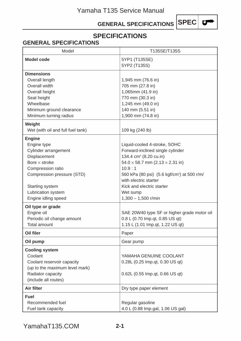
SPECIFICATIONSGENERAL SPECIFICATIONS
Model T135SE/T135S
Model code 5YP1 (T135SE)5YP2 (T135S)
DimensionsOverall length 1,945 mm (76.6 in)Overall width 705 mm (27.8 in)Overall height 1,065mm (41.9 in)Seat height 770 mm (30.3 in)Wheelbase 1,245 mm (49.0 in)Minimum ground clearance 140 mm (5.51 in)Minimum turning radius 1,900 mm (74.8 in)
WeightWet (with oil and full fuel tank) 109 kg (240 lb)
EngineEngine type Liquid-cooled 4-stroke, SOHCCylinder arrangement Forward-inclined single cylinderDisplacement 134.4 cm3 (8.20 cu.in)Bore × stroke 54.0 × 58.7 mm (2.13 × 2.31 in)Compression ratio 10.9 : 1Compression pressure (STD) 560 kPa (80 psi) (5.6 kgf/cm2) at 500 r/m/
with electric starterStarting system Kick and electric starterLubrication system Wet sumpEngine idling speed 1,300 – 1,500 r/min
Oil type or gradeEngine oil SAE 20W40 type SF or higher grade motor oilPeriodic oil change amount 0.8 L (0.70 Imp.qt, 0.85 US qt)Total amount 1.15 L (1.01 Imp.qt, 1.22 US qt)
Oil filer Paper
Oil pump Gear pump
Cooling systemCoolant YAMAHA GENUINE COOLANTCoolant reservoir capacity 0.28L (0.25 Imp.qt, 0.30 US qt)(up to the maximum level mark)Radiator capacity 0.62L (0.55 Imp.qt, 0.66 US qt)(include all routes)
Air filter Dry type paper element
FuelRecommended fuel Regular gasolineFuel tank capacity 4.0 L (0.88 Imp.gal, 1.06 US gal)
5YP-F8197-E0_2_1 05.6.27 19:46 Page 1
Yamaha T135 Service Manual
YamahaT135.COM
SPECGENERAL SPECIFICATIONS
2-2
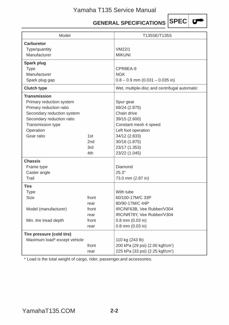
Model T135SE/T135S
CarburetorType/quantity VM22/1Manufacturer MIKUNI
Spark plugType CPR8EA-9Manufacturer NGKSpark plug gap 0.8 – 0.9 mm (0.031 – 0.035 in)
Clutch type Wet, multiple-disc and centrifugal automatic
TransmissionPrimary reduction system Spur gearPrimary reduction ratio 69/24 (2.875)Secondary reduction system Chain driveSecondary reduction ratio 39/15 (2.600)Transmission type Constant mesh 4 speedOperation Left foot operationGear ratio 1st 34/12 (2.833)
2nd 30/16 (1.875)3rd 23/17 (1.353)4th 23/22 (1.045)
ChassisFrame type DiamondCaster angle 25.3°Trail 73.0 mm (2.87 in)
TireType With tubeSize front 60/100-17M/C 33P
rear 80/90-17M/C 44PModel (manufacturer) front IRC/NF63B, Vee Rubber/V304
rear IRC/NR78Y, Vee Rubber/V304Min. tire tread depth front 0.8 mm (0.03 in)
rear 0.8 mm (0.03 in)
Tire pressure (cold tire)Maximum load*-except vehicle 110 kg (243 lb)
front 200 kPa (29 psi) (2.00 kgf/cm2)rear 225 kPa (33 psi) (2.25 kgf/cm2)
* Load is the total weight of cargo, rider, passenger,and accessories.
5YP-F8197-E0_2_1 05.6.27 19:46 Page 2
Yamaha T135 Service Manual
YamahaT135.COM
SPECGENERAL SPECIFICATIONS
2-3
Model T135SE/T135S
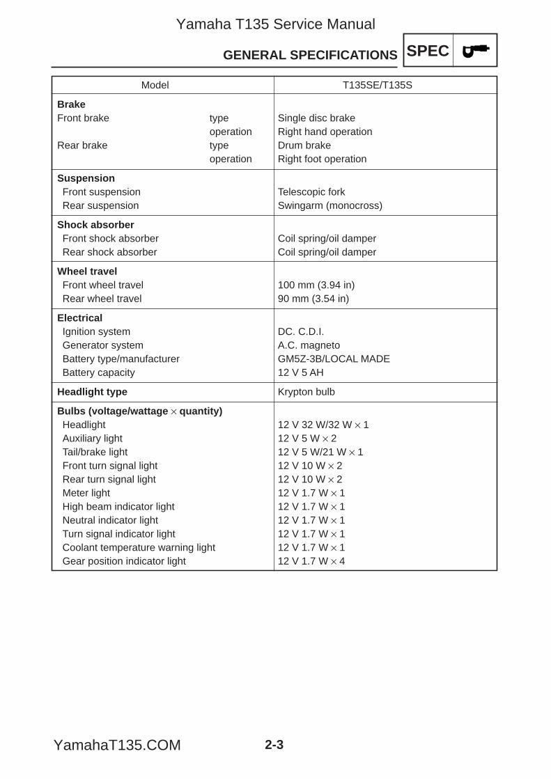
BrakeFront brake type Single disc brake
operation Right hand operationRear brake type Drum brake
operation Right foot operation
SuspensionFront suspension Telescopic forkRear suspension Swingarm (monocross)
Shock absorberFront shock absorber Coil spring/oil damperRear shock absorber Coil spring/oil damper
Wheel travelFront wheel travel 100 mm (3.94 in)Rear wheel travel 90 mm (3.54 in)
ElectricalIgnition system DC. C.D.I.Generator system A.C. magnetoBattery type/manufacturer GM5Z-3B/LOCAL MADEBattery capacity 12 V 5 AH
Headlight type Krypton bulb
Bulbs (voltage/wattage × quantity)Headlight 12 V 32 W/32 W × 1Auxiliary light 12 V 5 W × 2Tail/brake light 12 V 5 W/21 W × 1Front turn signal light 12 V 10 W × 2Rear turn signal light 12 V 10 W × 2Meter light 12 V 1.7 W × 1High beam indicator light 12 V 1.7 W × 1Neutral indicator light 12 V 1.7 W × 1Turn signal indicator light 12 V 1.7 W × 1Coolant temperature warning light 12 V 1.7 W × 1Gear position indicator light 12 V 1.7 W × 4
5YP-F8197-E0_2_1 05.6.27 19:46 Page 3
Yamaha T135 Service Manual
YamahaT135.COM
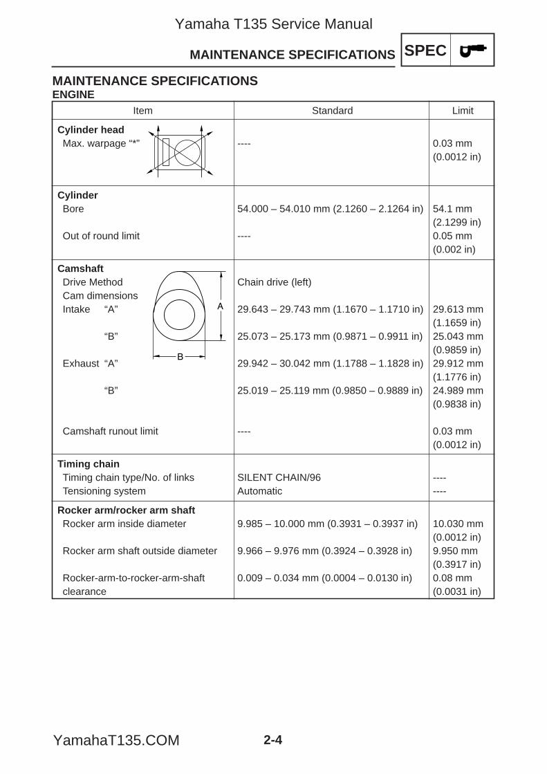
Item Standard Limit
Cylinder headMax. warpage “*” ---- 0.03 mm
(0.0012 in)
CylinderBore 54.000 – 54.010 mm (2.1260 – 2.1264 in) 54.1 mm
(2.1299 in)Out of round limit ---- 0.05 mm
(0.002 in)
CamshaftDrive Method Chain drive (left)Cam dimensionsIntake “A” 29.643 – 29.743 mm (1.1670 – 1.1710 in) 29.613 mm
(1.1659 in)“B” 25.073 – 25.173 mm (0.9871 – 0.9911 in) 25.043 mm
(0.9859 in)Exhaust “A” 29.942 – 30.042 mm (1.1788 – 1.1828 in) 29.912 mm
(1.1776 in)“B” 25.019 – 25.119 mm (0.9850 – 0.9889 in) 24.989 mm
(0.9838 in)
Camshaft runout limit ---- 0.03 mm (0.0012 in)
Timing chainTiming chain type/No. of links SILENT CHAIN/96 ----Tensioning system Automatic ----
Rocker arm/rocker arm shaftRocker arm inside diameter 9.985 – 10.000 mm (0.3931 – 0.3937 in) 10.030 mm
(0.0012 in)Rocker arm shaft outside diameter 9.966 – 9.976 mm (0.3924 – 0.3928 in) 9.950 mm
(0.3917 in)Rocker-arm-to-rocker-arm-shaft 0.009 – 0.034 mm (0.0004 – 0.0130 in) 0.08 mm clearance (0.0031 in)
SPECMAINTENANCE SPECIFICATIONS
2-4
MAINTENANCE SPECIFICATIONSENGINE
A
B
5YP-F8197-E0_2_1 05.6.27 19:46 Page 4
Yamaha T135 Service Manual
YamahaT135.COM
SPECMAINTENANCE SPECIFICATIONS
2-5
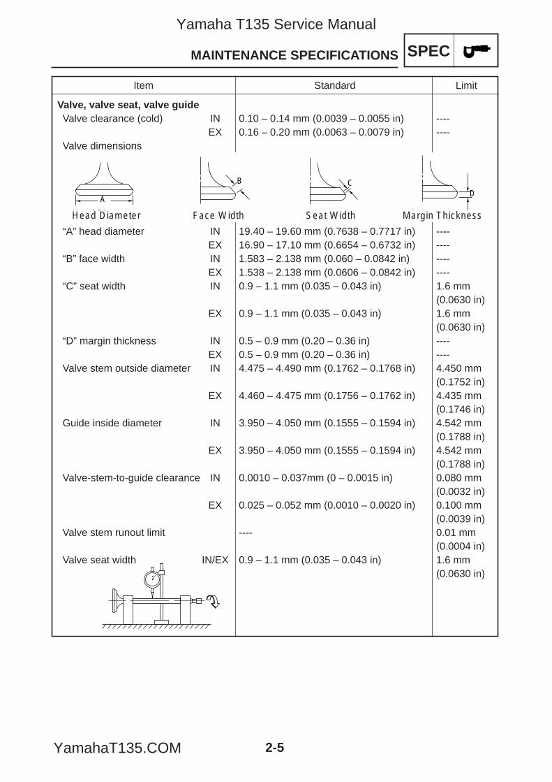
Item Standard Limit
Valve, valve seat, valve guideValve clearance (cold) IN 0.10 – 0.14 mm (0.0039 – 0.0055 in) ----
EX 0.16 – 0.20 mm (0.0063 – 0.0079 in) ----Valve dimensions
“A” head diameter IN 19.40 – 19.60 mm (0.7638 – 0.7717 in) ----EX 16.90 – 17.10 mm (0.6654 – 0.6732 in) ----
“B” face width IN 1.583 – 2.138 mm (0.060 – 0.0842 in) ----EX 1.538 – 2.138 mm (0.0606 – 0.0842 in) ----
“C” seat width IN 0.9 – 1.1 mm (0.035 – 0.043 in) 1.6 mm (0.0630 in)
EX 0.9 – 1.1 mm (0.035 – 0.043 in) 1.6 mm (0.0630 in)
“D” margin thickness IN 0.5 – 0.9 mm (0.20 – 0.36 in) ----EX 0.5 – 0.9 mm (0.20 – 0.36 in) ----
Valve stem outside diameter IN 4.475 – 4.490 mm (0.1762 – 0.1768 in) 4.450 mm (0.1752 in)
EX 4.460 – 4.475 mm (0.1756 – 0.1762 in) 4.435 mm (0.1746 in)
Guide inside diameter IN 3.950 – 4.050 mm (0.1555 – 0.1594 in) 4.542 mm (0.1788 in)
EX 3.950 – 4.050 mm (0.1555 – 0.1594 in) 4.542 mm (0.1788 in)
Valve-stem-to-guide clearance IN 0.0010 – 0.037mm (0 – 0.0015 in) 0.080 mm (0.0032 in)
EX 0.025 – 0.052 mm (0.0010 – 0.0020 in) 0.100 mm (0.0039 in)
Valve stem runout limit ---- 0.01 mm (0.0004 in)
Valve seat width IN/EX 0.9 – 1.1 mm (0.035 – 0.043 in) 1.6 mm (0.0630 in)
A
H d DiHead Diameter
C
Seat Width
D
Margin Thickness
B
Face Width
5YP-F8197-E0_2_1 05.6.27 19:46 Page 5
Yamaha T135 Service Manual
YamahaT135.COM
SPEC
2-6
MAINTENANCE SPECIFICATIONS
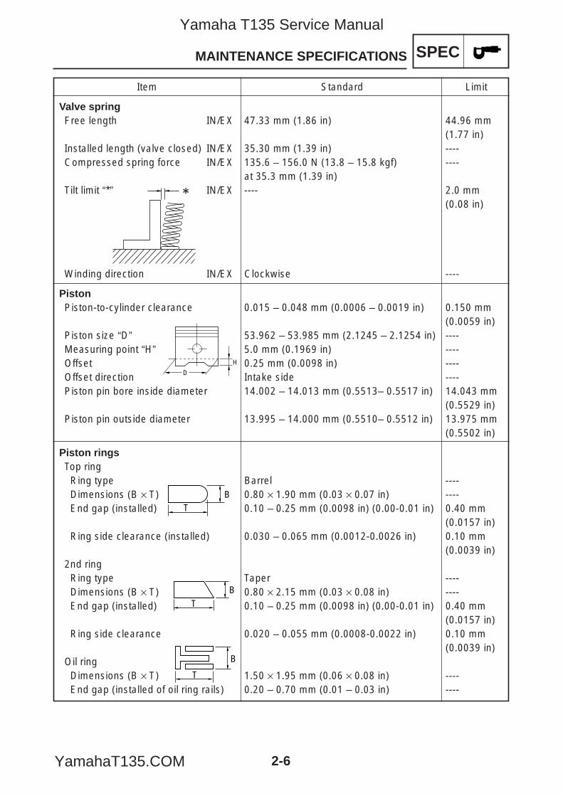
Item Standard Limit
Valve springFree length IN/EX 47.33 mm (1.86 in) 44.96 mm
(1.77 in)Installed length (valve closed) IN/EX 35.30 mm (1.39 in) ----Compressed spring force IN/EX 135.6 – 156.0 N (13.8 – 15.8 kgf) ----
at 35.3 mm (1.39 in)Tilt limit “*” IN/EX ---- 2.0 mm
(0.08 in)
Winding direction IN/EX Clockwise ----
PistonPiston-to-cylinder clearance 0.015 – 0.048 mm (0.0006 – 0.0019 in) 0.150 mm
(0.0059 in)Piston size “D” 53.962 – 53.985 mm (2.1245 – 2.1254 in) ----Measuring point “H” 5.0 mm (0.1969 in) ----Offset 0.25 mm (0.0098 in) ----Offset direction Intake side ----Piston pin bore inside diameter 14.002 – 14.013 mm (0.5513– 0.5517 in) 14.043 mm
(0.5529 in)Piston pin outside diameter 13.995 – 14.000 mm (0.5510– 0.5512 in) 13.975 mm
(0.5502 in)
Piston ringsTop ringRing type Barrel ----Dimensions (B × T) 0.80 × 1.90 mm (0.03 × 0.07 in) ----End gap (installed) 0.10 – 0.25 mm (0.0098 in) (0.00-0.01 in) 0.40 mm
(0.0157 in)Ring side clearance (installed) 0.030 – 0.065 mm (0.0012-0.0026 in) 0.10 mm
(0.0039 in)2nd ringRing type Taper ----Dimensions (B × T) 0.80 × 2.15 mm (0.03 × 0.08 in) ----End gap (installed) 0.10 – 0.25 mm (0.0098 in) (0.00-0.01 in) 0.40 mm
(0.0157 in)Ring side clearance 0.020 – 0.055 mm (0.0008-0.0022 in) 0.10 mm
(0.0039 in)Oil ringDimensions (B × T) 1.50 × 1.95 mm (0.06 × 0.08 in) ----End gap (installed of oil ring rails) 0.20 – 0.70 mm (0.01 – 0.03 in) ----
TB
BT
B
T
H
D
5YP-F8197-E0_2_1 05.6.27 19:46 Page 6
Yamaha T135 Service Manual
YamahaT135.COM
SPEC
2-7
MAINTENANCE SPECIFICATIONS
Item Standard Limit
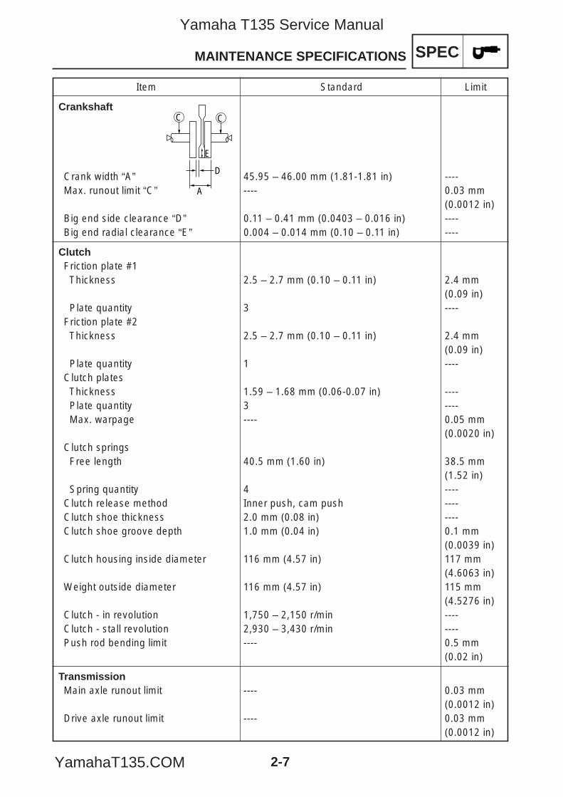
Crankshaft
Crank width “A” 45.95 – 46.00 mm (1.81-1.81 in) ----Max. runout limit “C” ---- 0.03 mm
(0.0012 in)Big end side clearance “D” 0.11 – 0.41 mm (0.0403 – 0.016 in) ----Big end radial clearance “E” 0.004 – 0.014 mm (0.10 – 0.11 in) ----
ClutchFriction plate #1Thickness 2.5 – 2.7 mm (0.10 – 0.11 in) 2.4 mm
(0.09 in)Plate quantity 3 ----
Friction plate #2Thickness 2.5 – 2.7 mm (0.10 – 0.11 in) 2.4 mm
(0.09 in)Plate quantity 1 ----
Clutch platesThickness 1.59 – 1.68 mm (0.06-0.07 in) ----Plate quantity 3 ----Max. warpage ---- 0.05 mm
(0.0020 in)Clutch springsFree length 40.5 mm (1.60 in) 38.5 mm
(1.52 in)Spring quantity 4 ----
Clutch release method Inner push, cam push ----Clutch shoe thickness 2.0 mm (0.08 in) ----Clutch shoe groove depth 1.0 mm (0.04 in) 0.1 mm
(0.0039 in)Clutch housing inside diameter 116 mm (4.57 in) 117 mm
(4.6063 in)Weight outside diameter 116 mm (4.57 in) 115 mm
(4.5276 in)Clutch - in revolution 1,750 – 2,150 r/min ----Clutch - stall revolution 2,930 – 3,430 r/min ----Push rod bending limit ---- 0.5 mm
(0.02 in)
TransmissionMain axle runout limit ---- 0.03 mm
(0.0012 in)Drive axle runout limit ---- 0.03 mm
(0.0012 in)
CC
D
A
E
5YP-F8197-E0_2_1 05.6.27 19:46 Page 7
Yamaha T135 Service Manual
YamahaT135.COM
Item Standard Limit
KickstarterKickstarter type Ratchet type ----Spring free length 15.5 mm (0.61 in) ----
CarburetorType VM22 ----I.D. mark 5YP1 00 ----Main jet (M.J) #105 ----Main air jet (M.A.J) ø1.2 ----Jet needle (J.N) 5 K010 ----Needle jet (N.J) N-9M ----Pilot outlet (P.O) ø1 ----Pilot jet (P.J) #20 ----Pilot air screw turns out 1-5/8 ----Pilot air jet 1 #55 ----Valve seat size ø2 ----Throttle valve size #2.0 ----Float height 9.2 mm (0.3622 in) ----
Oil pumpOil pump type Trochoid type ----Inner-rotor-to-outer-rotor-tip clear- 0.15 mm (0.0059 in) 0.20 mm ance (0.0079 in)Outer-rotor-to-oil-pump housing 0.06 – 0.11 mm 0.15 mm clearance (0.0024 – 0.0043 in) (0.0059 in)Oil-pump-housing-to-inner-rotor-and- 0.06 – 0.11 mm 0.15 mm outer-rotor clearance (0.0024 – 0.0043 in) (0.0059 in)
SPEC
2-8
MAINTENANCE SPECIFICATIONS
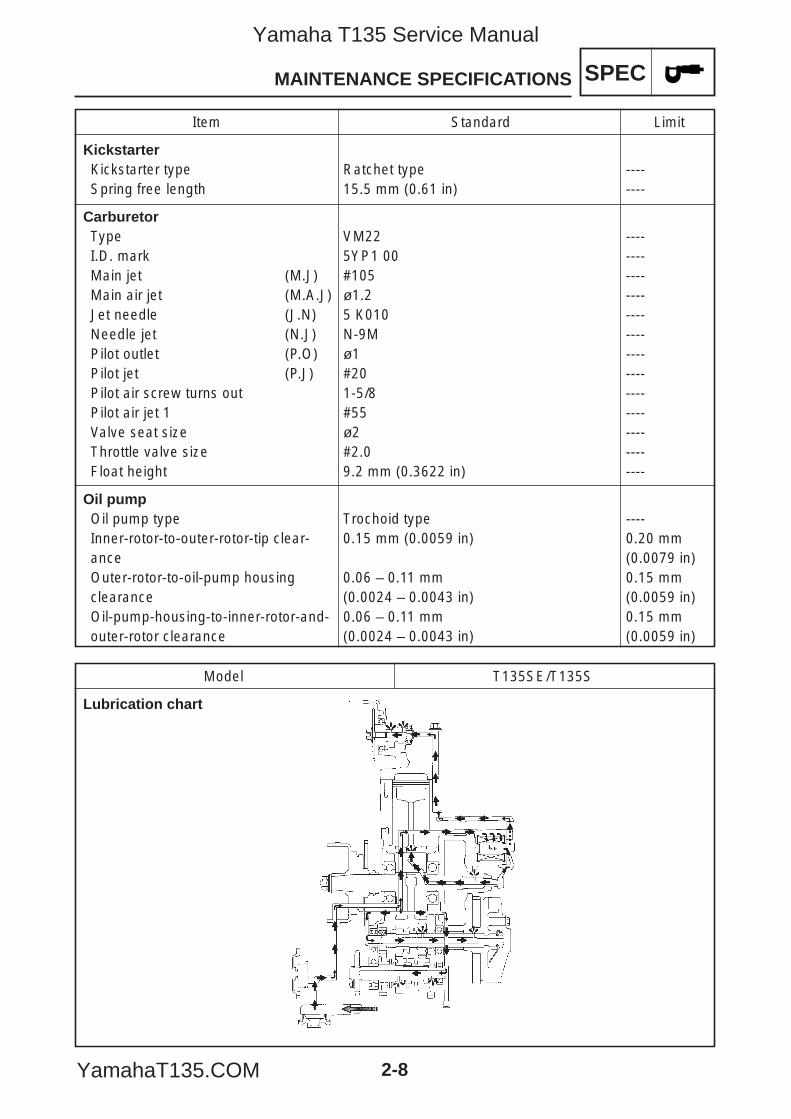
Model T135SE/T135S
Lubrication chart
5YP-F8197-E0_2_1 05.6.27 19:46 Page 8
Yamaha T135 Service Manual
YamahaT135.COM
SPECMAINTENANCE SPECIFICATIONS
2-9
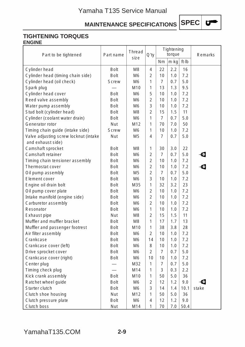
TIGHTENING TORQUESENGINE
Cylinder head Bolt M8 4 22 2.2 16 Cylinder head (timing chain side) Bolt M6 2 10 1.0 7.2 Cylinder head (oil check) Screw M6 1 7 0.7 5.0 Spark plug — M10 1 13 1.3 9.5 Cylinder head cover Bolt M6 5 10 1.0 7.2Reed valve assembly Bolt M6 2 10 1.0 7.2Water pump assembly Bolt M6 3 10 1.0 7.2Stud bolt (cylinder head) Bolt M8 2 15 1.5 11 Cylinder (coolant water drain) Bolt M6 1 7 0.7 5.0 Generator rotor Nut M12 1 70 7.0 50 Timing chain guide (intake side) Screw M6 1 10 1.0 7.2 Valve adjusting screw locknut (intake Nut M5 4 7 0.7 5.0 and exhaust side)Camshaft sprocket Bolt M8 1 30 3.0 22Camshaft retainer Bolt M6 2 7 0.7 5.0 Timing chain tensioner assembly Bolt M6 2 10 1.0 7.2 Thermostat cover Bolt M6 2 10 1.0 7.2Oil pump assembly Bolt M5 2 7 0.7 5.0 Element cover Bolt M6 3 10 1.0 7.2Engine oil drain bolt Bolt M35 1 32 3.2 23Oil pump cover plate Bolt M6 2 10 1.0 7.2 Intake manifold (engine side) Bolt M6 2 10 1.0 7.2 Carburetor assembly Bolt M6 2 10 1.0 7.2 Resonator Bolt M6 1 10 1.0 7.2Exhaust pipe Nut M8 2 15 1.5 11 Muffler and muffler bracket Bolt M8 1 17 1.7 13Muffler and passenger footrest Bolt M10 1 38 3.8 28Air filter assembly Bolt M6 2 10 1.0 7.2 Crankcase Bolt M6 14 10 1.0 7.2 Crankcase cover (left) Bolt M6 8 10 1.0 7.2 Drive sprocket cover Bolt M6 2 7 0.7 5.0 Crankcase cover (right) Bolt M6 10 10 1.0 7.2 Center plug — M32 1 7 0.7 5.0 Timing check plug — M14 1 3 0.3 2.2 Kick crank assembly Bolt M10 1 50 5.0 36 Ratchet wheel guide Bolt M6 2 12 1.2 9.0Starter clutch Bolt M6 3 14 1.4 10.1 stakeClutch shoe housing Nut M12 1 50 5.0 36 Clutch pressure plate Bolt M6 4 12 1.2 9.0Clutch boss Nut M14 1 70 7.0 50.4
Part to be tightened Part nameThread
sizeQ’ty
Tighteningtorque Remarks
Nm m·kg ft·lb
LT
LT
LT
5YP-F8197-E0_2_1 05.6.27 19:46 Page 9
Yamaha T135 Service Manual
YamahaT135.COM
SPEC
2-10
MAINTENANCE SPECIFICATIONS
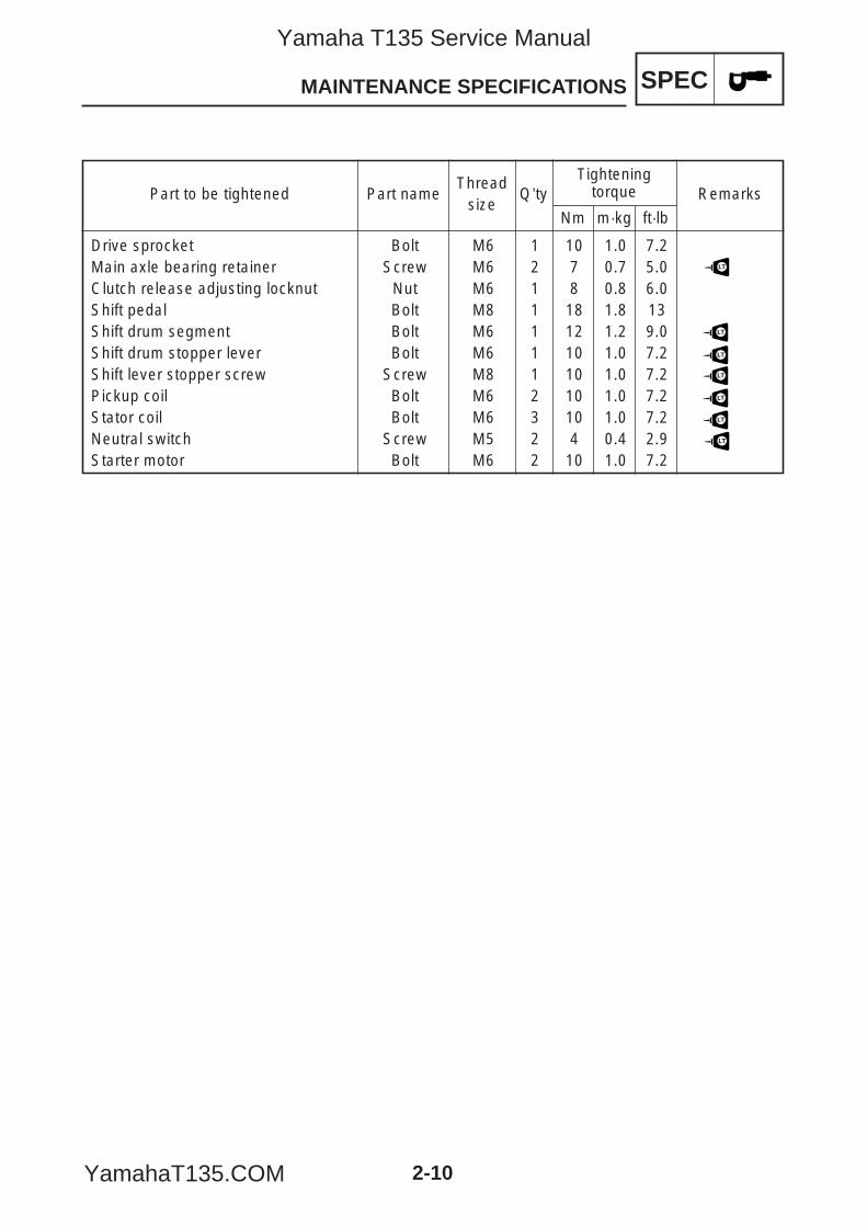
Drive sprocket Bolt M6 1 10 1.0 7.2 Main axle bearing retainer Screw M6 2 7 0.7 5.0 Clutch release adjusting locknut Nut M6 1 8 0.8 6.0Shift pedal Bolt M8 1 18 1.8 13Shift drum segment Bolt M6 1 12 1.2 9.0Shift drum stopper lever Bolt M6 1 10 1.0 7.2Shift lever stopper screw Screw M8 1 10 1.0 7.2Pickup coil Bolt M6 2 10 1.0 7.2 Stator coil Bolt M6 3 10 1.0 7.2 Neutral switch Screw M5 2 4 0.4 2.9 Starter motor Bolt M6 2 10 1.0 7.2
Part to be tightened Part nameThread
sizeQ’ty
Tighteningtorque Remarks
Nm m·kg ft·lb
LT
LT
LT
LT
LT
LT
LT
5YP-F8197-E0_2_1 05.6.27 19:46 Page 10
Yamaha T135 Service Manual
YamahaT135.COM
Item Standard Limit
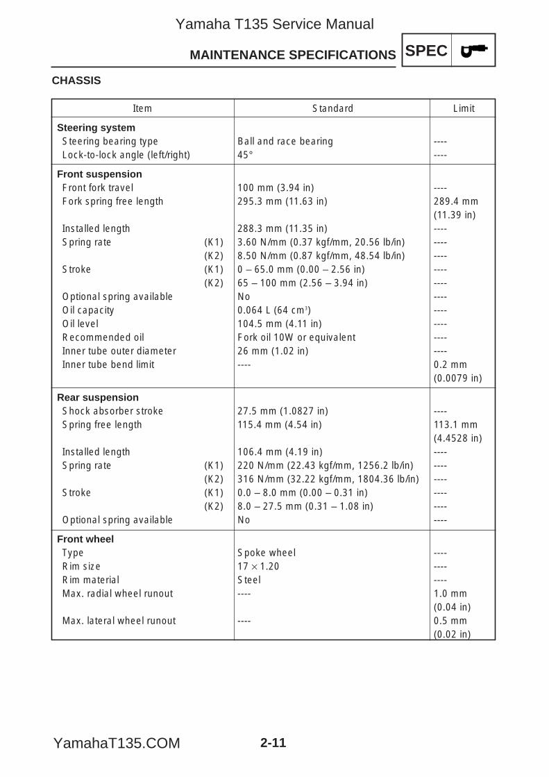
Steering systemSteering bearing type Ball and race bearing ----Lock-to-lock angle (left/right) 45° ----
Front suspensionFront fork travel 100 mm (3.94 in) ----Fork spring free length 295.3 mm (11.63 in) 289.4 mm
(11.39 in)Installed length 288.3 mm (11.35 in) ----Spring rate (K1) 3.60 N/mm (0.37 kgf/mm, 20.56 lb/in) ----
(K2) 8.50 N/mm (0.87 kgf/mm, 48.54 lb/in) ----Stroke (K1) 0 – 65.0 mm (0.00 – 2.56 in) ----
(K2) 65 – 100 mm (2.56 – 3.94 in) ----Optional spring available No ----Oil capacity 0.064 L (64 cm3) ----Oil level 104.5 mm (4.11 in) ----Recommended oil Fork oil 10W or equivalent ----Inner tube outer diameter 26 mm (1.02 in) ----Inner tube bend limit ---- 0.2 mm
(0.0079 in)
Rear suspensionShock absorber stroke 27.5 mm (1.0827 in) ----Spring free length 115.4 mm (4.54 in) 113.1 mm
(4.4528 in)Installed length 106.4 mm (4.19 in) ----Spring rate (K1) 220 N/mm (22.43 kgf/mm, 1256.2 lb/in) ----
(K2) 316 N/mm (32.22 kgf/mm, 1804.36 lb/in) ----Stroke (K1) 0.0 – 8.0 mm (0.00 – 0.31 in) ----
(K2) 8.0 – 27.5 mm (0.31 – 1.08 in) ----Optional spring available No ----
Front wheelType Spoke wheel ----Rim size 17 × 1.20 ----Rim material Steel ----Max. radial wheel runout ---- 1.0 mm
(0.04 in)Max. lateral wheel runout ---- 0.5 mm
(0.02 in)
SPEC
2-11
MAINTENANCE SPECIFICATIONS
CHASSIS
5YP-F8197-E0_2_1 05.6.27 19:46 Page 11
Yamaha T135 Service Manual
YamahaT135.COM
Item Standard Limit
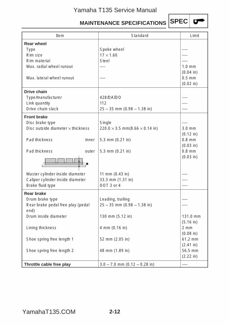
Rear wheelType Spoke wheel ----Rim size 17 × 1.60 ----Rim material Steel ----Max. radial wheel runout ---- 1.0 mm
(0.04 in)Max. lateral wheel runout ---- 0.5 mm
(0.02 in)
Drive chainType/manufacturer 428/DAIDO ----Link quantity 112 ----Drive chain slack 25 – 35 mm (0.98 – 1.38 in) ----
Front brakeDisc brake type Single ----Disc outside diameter × thickness 220.0 × 3.5 mm(8.66 × 0.14 in) 3.0 mm
(0.12 in)Pad thickness inner 5.3 mm (0.21 in) 0.8 mm
(0.03 in)Pad thickness outer 5.3 mm (0.21 in) 0.8 mm
(0.03 in)
Master cylinder inside diameter 11 mm (0.43 in) ----Caliper cylinder inside diameter 33.3 mm (1.31 in) ----Brake fluid type DOT 3 or 4 ----
Rear brakeDrum brake type Leading, trailing ----Rear brake pedal free play (pedal 25 – 35 mm (0.98 – 1.38 in) ----end)Drum inside diameter 130 mm (5.12 in) 131.0 mm
(5.16 in)Lining thickness 4 mm (0.16 in) 2 mm
(0.08 in)Shoe spring free length 1 52 mm (2.05 in) 61.2 mm
(2.41 in)Shoe spring free length 2 48 mm (1.89 in) 56.5 mm
(2.22 in)
Throttle cable free play 3.0 – 7.0 mm (0.12 – 0.28 in) ----
SPEC
2-12
MAINTENANCE SPECIFICATIONS
5YP-F8197-E0_2_1 05.6.27 19:46 Page 12
Yamaha T135 Service Manual
YamahaT135.COM
SPEC
2-13
MAINTENANCE SPECIFICATIONS
TIGHTENING TORQUESCHASSIS
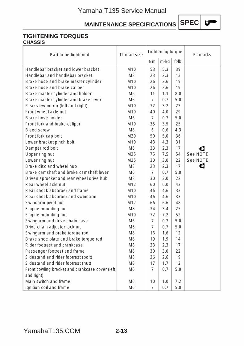
Handlebar bracket and lower bracket M10 53 5.3 39 Handlebar and handlebar bracket M8 23 2.3 13 Brake hose and brake master cylinder M10 26 2.6 19Brake hose and brake caliper M10 26 2.6 19 Brake master cylinder and holder M6 11 1.1 8.0 Brake master cylinder and brake lever M6 7 0.7 5.0 Rear view mirror (left and right) M10 32 3.2 23 Front wheel axle nut M10 40 4.0 29 Brake hose holder M6 7 0.7 5.0 Front fork and brake caliper M10 35 3.5 25 Bleed screw M8 6 0.6 4.3 Front fork cap bolt M20 50 5.0 36 Lower bracket pinch bolt M10 43 4.3 31 Damper rod bolt M8 23 2.3 17 Upper ring nut M25 75 7.5 54 See NOTELower ring nut M25 30 3.0 22 See NOTEBrake disc and wheel hub M8 23 2.3 17 Brake camshaft and brake camshaft lever M6 7 0.7 5.0 Driven sprocket and rear wheel drive hub M8 30 3.0 22 Rear wheel axle nut M12 60 6.0 43 Rear shock absorber and frame M10 46 4.6 33 Rear shock absorber and swingarm M10 46 4.6 33 Swingarm pivot nut M12 66 6.6 48 Engine mounting nut M8 34 3.4 25 Engine mounting nut M10 72 7.2 52 Swingarm and drive chain case M6 7 0.7 5.0 Drive chain adjuster locknut M6 7 0.7 5.0 Swingarm and brake torque rod M8 16 1.6 12 Brake shoe plate and brake torque rod M8 19 1.9 14 Rider footrest and crankcase M8 23 2.3 17 Passenger footrest and frame M8 30 3.0 22 Sidestand and rider footrest (bolt) M8 26 2.6 19 Sidestand and rider footrest (nut) M8 17 1.7 12 Front cowling bracket and crankcase cover (left M6 7 0.7 5.0 and right)Main switch and frame M6 10 1.0 7.2 Ignition coil and frame M6 7 0.7 5.0
Part to be tightened Thread sizeTightening torque
Remarks
Nm m·kg ft·lb
LT
LT
5YP-F8197-E0_2_1 05.6.27 19:46 Page 13
Yamaha T135 Service Manual
YamahaT135.COM
SPEC
2-14
MAINTENANCE SPECIFICATIONS
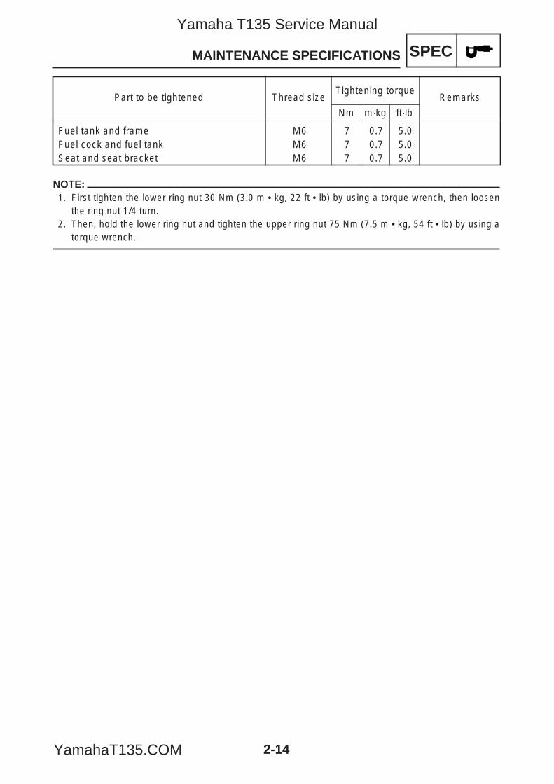
NOTE:1. First tighten the lower ring nut 30 Nm (3.0 m • kg, 22 ft • lb) by using a torque wrench, then loosen
the ring nut 1/4 turn.2. Then, hold the lower ring nut and tighten the upper ring nut 75 Nm (7.5 m • kg, 54 ft • lb) by using a
torque wrench.
Fuel tank and frame M6 7 0.7 5.0 Fuel cock and fuel tank M6 7 0.7 5.0 Seat and seat bracket M6 7 0.7 5.0
Part to be tightened Thread sizeTightening torque
Remarks
Nm m·kg ft·lb
5YP-F8197-E0_2_1 05.6.27 19:46 Page 14
Yamaha T135 Service Manual
YamahaT135.COM
SPEC
2-15
MAINTENANCE SPECIFICATIONS
ELECTRICAL
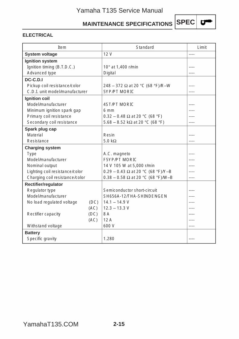
Item Standard Limit
System voltage 12 V ----
Ignition systemIgnition timing (B.T.D.C.) 10° at 1,400 r/min ----Advanced type Digital ----
DC-C.D.IPickup coil resistance/color 248 – 372 Ω at 20 °C (68 °F)/R–W ----C.D.I. unit model/manufacturer 5YP/PT MORIC ----
Ignition coilModel/manufacturer 4ST/PT MORIC ----Minimum ignition spark gap 6 mm ----Primary coil resistance 0.32 – 0.48 Ω at 20 °C (68 °F) ----Secondary coil resistance 5.68 – 8.52 kΩ at 20 °C (68 °F) ----
Spark plug capMaterial Resin ----Resistance 5.0 kΩ ----
Charging systemType A.C. magneto ----Model/manufacturer F5YP/PT MORIC ----Nominal output 14 V 105 W at 5,000 r/min ----Lighting coil resistance/color 0.29 – 0.43 Ω at 20 °C (68 °F)/Y–B ----Charging coil resistance/color 0.38 – 0.58 Ω at 20 °C (68 °F)/W–B ----
Rectifier/regulatorRegulator type Semiconductor short-circuit ----Model/manufacturer SH656A-12/THA-SHINDENGEN ----No load regulated voltage (DC) 14.1 – 14.9 V ----
(AC) 12.3 – 13.3 V ----Rectifier capacity (DC) 8 A ----
(AC) 12 A ----Withstand voltage 600 V ----
BatterySpecific gravity 1.280 ----
5YP-F8197-E0_2_1 05.6.27 19:46 Page 15
Yamaha T135 Service Manual
YamahaT135.COM
SPEC
2-16
MAINTENANCE SPECIFICATIONS
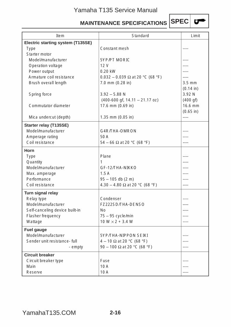
Item Standard Limit
Electric starting system (T135SE)Type Constant mesh ----Starter motorModel/manufacturer 5YP/PT MORIC ----Operation voltage 12 V ----Power output 0.20 kW ----Armature coil resistance 0.032 – 0.039 Ω at 20 °C (68 °F) ----Brush overall length 7.0 mm (0.28 in) 3.5 mm
(0.14 in)Spring force 3.92 – 5.88 N 3.92 N
(400-600 gf, 14.11 – 21.17 oz) (400 gf)Commutator diameter 17.6 mm (0.69 in) 16.6 mm
(0.65 in)Mica undercut (depth) 1.35 mm (0.05 in) ----
Starter relay (T135SE)Model/manufacturer G4R/THA-OMRON ----Amperage rating 50 A ----Coil resistance 54 – 66 Ω at 20 °C (68 °F) ----
HornType Plane ----Quantity 1 ----Model/manufacturer GF-12/THA-NIKKO ----Max. amperage 1.5 A ----Performance 95 – 105 db (2 m) ----Coil resistance 4.30 – 4.80 Ω at 20 °C (68 °F) ----
Turn signal relayRelay type Condenser ----Model/manufacturer FZ222SD/THA-DENSO ----Self-canceling device built-in No ----Flasher frequency 75 – 95 cycle/min ----Wattage 10 W × 2 + 3.4 W ----
Fuel gaugeModel/manufacturer 5YP/THA-NIPPON SEIKI ----Sender unit resistance- full 4 – 10 Ω at 20 °C (68 °F) ----
- empty 90 – 100 Ω at 20 °C (68 °F) ----
Circuit breakerCircuit breaker type Fuse ----Main 10 A ----Reserve 10 A ----
5YP-F8197-E0_2_1 05.6.27 19:46 Page 16
Yamaha T135 Service Manual
YamahaT135.COM
SPEC
2-17
CONVERSION TABLE/GENERAL TIGHTENING TORQUE SPECIFICATIONS
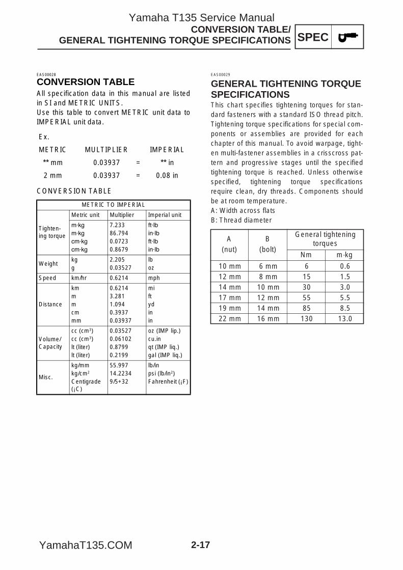
EAS00029
GENERAL TIGHTENING TORQUESPECIFICATIONSThis chart specifies tightening torques for stan-dard fasteners with a standard ISO thread pitch.Tightening torque specifications for special com-ponents or assemblies are provided for eachchapter of this manual. To avoid warpage, tight-en multi-fastener assemblies in a crisscross pat-tern and progressive stages until the specifiedtightening torque is reached. Unless otherwisespecified, tightening torque specificationsrequire clean, dry threads. Components shouldbe at room temperature.A: Width across flatsB: Thread diameter
10 mm 6 mm 6 0.612 mm 8 mm 15 1.514 mm 10 mm 30 3.017 mm 12 mm 55 5.519 mm 14 mm 85 8.522 mm 16 mm 130 13.0
A(nut)
B(bolt)
General tighteningtorques
Nm m·kg
EAS00028
CONVERSION TABLEAll specification data in this manual are listedin SI and METRIC UNITS. Use this table to convert METRIC unit data toIMPERIAL unit data.
CONVERSION TABLE
Ex.
METRIC MULTIPLIER IMPERIAL
** mm 0.03937 = ** in
2 mm 0.03937 = 0.08 in
METRIC TO IMPERIAL
Tighten-ing torque
Metric unit Multiplier Imperial unit
7.23386.7940.07230.8679
Weightkgg
2.2050.03527
lboz
Speed km/hr 0.6214 mph
Distance
kmmmcmmm
0.62143.2811.0940.39370.03937
miftydinin
Volume/Capacity
cc (cm3)cc (cm3)lt (liter)lt (liter)
0.035270.061020.87990.2199
oz (IMP lip.)cu.inqt (IMP liq.)gal (IMP liq.)
Misc.
kg/mmkg/cm2
Centigrade (¡C)
55.99714.22349/5+32
lb/inpsi (lb/in2)Fahrenheit (¡F)
5YP-F8197-E0_2_1 05.6.27 19:46 Page 17
Yamaha T135 Service Manual
YamahaT135.COM
SPEC
2-18
LUBRICATION POINTS AND LUBRICANT TYPES
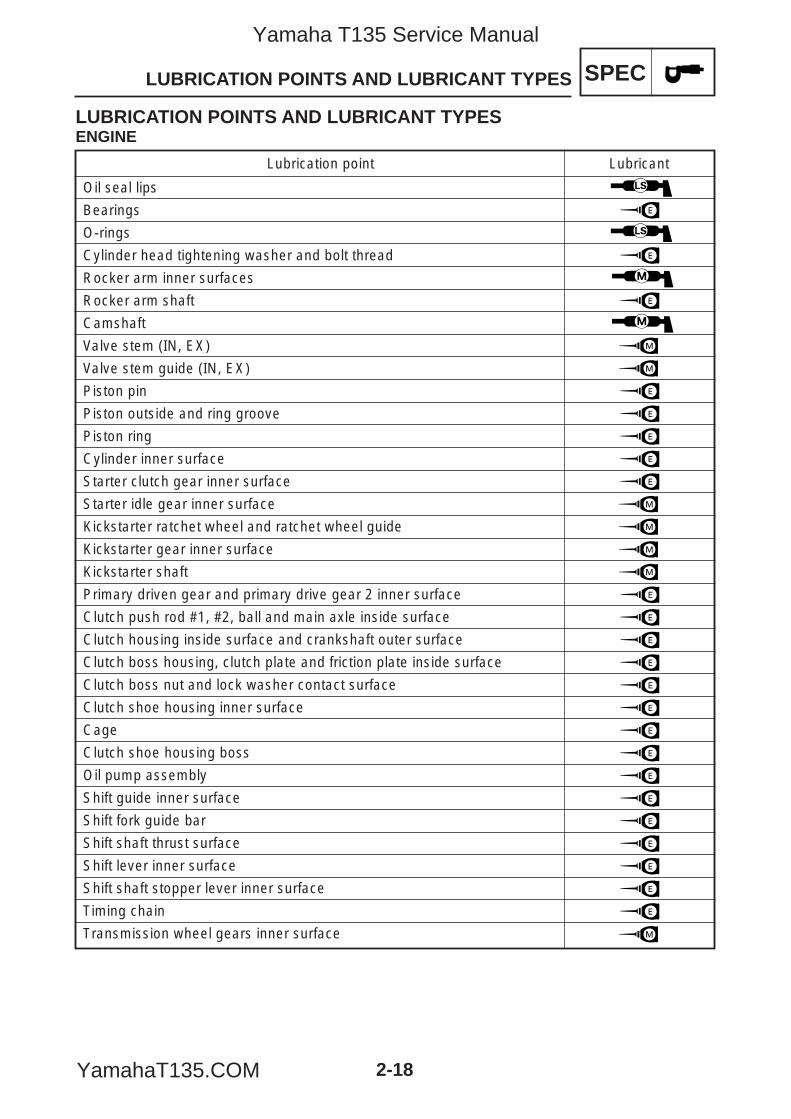
LUBRICATION POINTS AND LUBRICANT TYPESENGINE
Lubrication point Lubricant
Oil seal lips
Bearings
O-rings
Cylinder head tightening washer and bolt thread
Rocker arm inner surfaces
Rocker arm shaft
Camshaft
Valve stem (IN, EX)
Valve stem guide (IN, EX)
Piston pin
Piston outside and ring groove
Piston ring
Cylinder inner surface
Starter clutch gear inner surface
Starter idle gear inner surface
Kickstarter ratchet wheel and ratchet wheel guide
Kickstarter gear inner surface
Kickstarter shaft
Primary driven gear and primary drive gear 2 inner surface
Clutch push rod #1, #2, ball and main axle inside surface
Clutch housing inside surface and crankshaft outer surface
Clutch boss housing, clutch plate and friction plate inside surface
Clutch boss nut and lock washer contact surface
Clutch shoe housing inner surface
Cage
Clutch shoe housing boss
Oil pump assembly
Shift guide inner surface
Shift fork guide bar
Shift shaft thrust surface
Shift lever inner surface
Shift shaft stopper lever inner surface
Timing chain
Transmission wheel gears inner surface
5YP-F8197-E0_2_1 05.6.27 19:46 Page 18
Yamaha T135 Service Manual
YamahaT135.COM
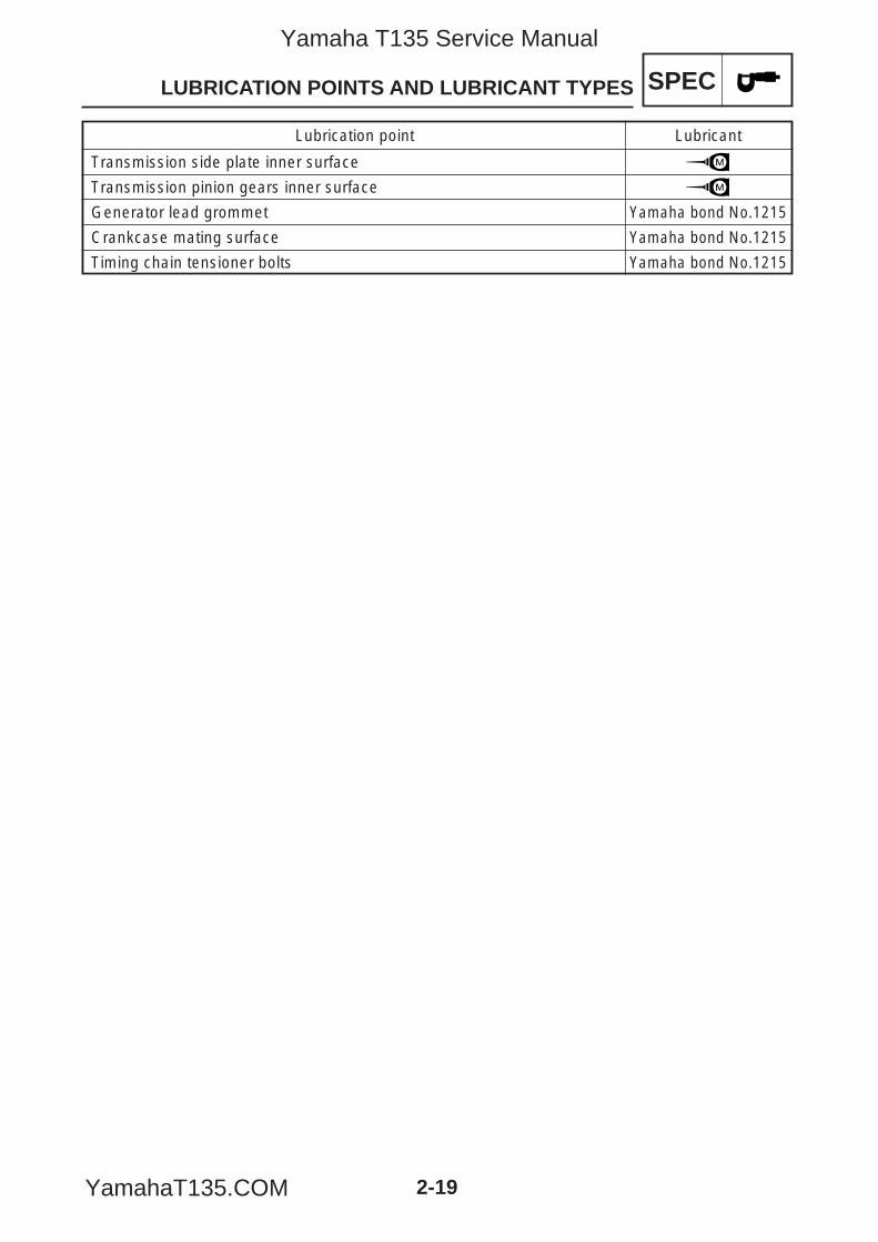
Lubrication point Lubricant
Transmission side plate inner surface
Transmission pinion gears inner surface
Generator lead grommet Yamaha bond No.1215
Crankcase mating surface Yamaha bond No.1215
Timing chain tensioner bolts Yamaha bond No.1215
SPEC
2-19
LUBRICATION POINTS AND LUBRICANT TYPES
5YP-F8197-E0_2_1 05.6.27 19:46 Page 19
Yamaha T135 Service Manual
YamahaT135.COM
SPEC
2-20
LUBRICATION POINTS AND LUBRICANT TYPES
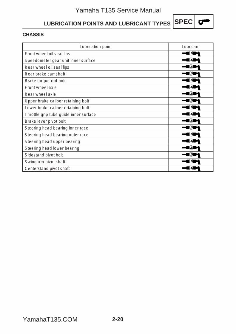
CHASSIS
Lubrication point Lubricant
Front wheel oil seal lips
Speedometer gear unit inner surface
Rear wheel oil seal lips
Rear brake camshaft
Brake torque rod bolt
Front wheel axle
Rear wheel axle
Upper brake caliper retaining bolt
Lower brake caliper retaining bolt
Throttle grip tube guide inner surface
Brake lever pivot bolt
Steering head bearing inner race
Steering head bearing outer race
Steering head upper bearing
Steering head lower bearing
Sidestand pivot bolt
Swingarm pivot shaft
Centerstand pivot shaft
5YP-F8197-E0_2_1 05.6.27 19:46 Page 20
Yamaha T135 Service Manual
YamahaT135.COM
SPEC
2-21
COOLING SYSTEM DIAGRAMS
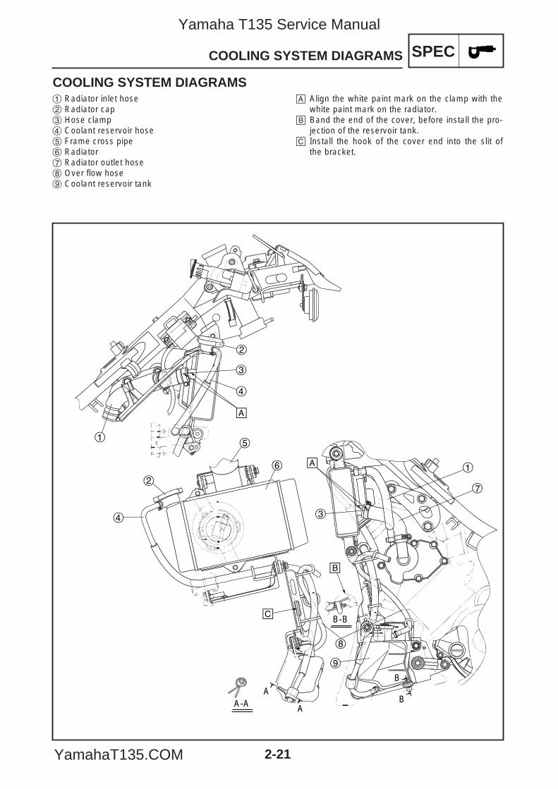
COOLING SYSTEM DIAGRAMS1 Radiator inlet hose2 Radiator cap3 Hose clamp4 Coolant reservoir hose5 Frame cross pipe6 Radiator7 Radiator outlet hose8 Over flow hose9 Coolant reservoir tank
å Align the white paint mark on the clamp with thewhite paint mark on the radiator.
∫ Band the end of the cover, before install the pro-jection of the reservoir tank.
ç Install the hook of the cover end into the slit ofthe bracket.
å
å
∫
ç
1
2
3
1
2
3
4
4
5
6
7
8
9
A
A
B
BA-A
B-B
5YP-F8197-E0_2_1 05.6.27 19:46 Page 21
Yamaha T135 Service Manual
YamahaT135.COM
SPEC
2-22
CABLE ROUTING
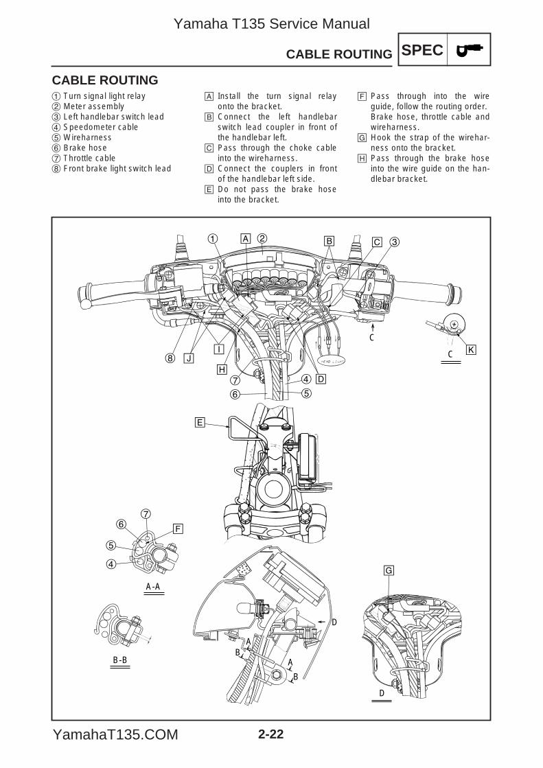
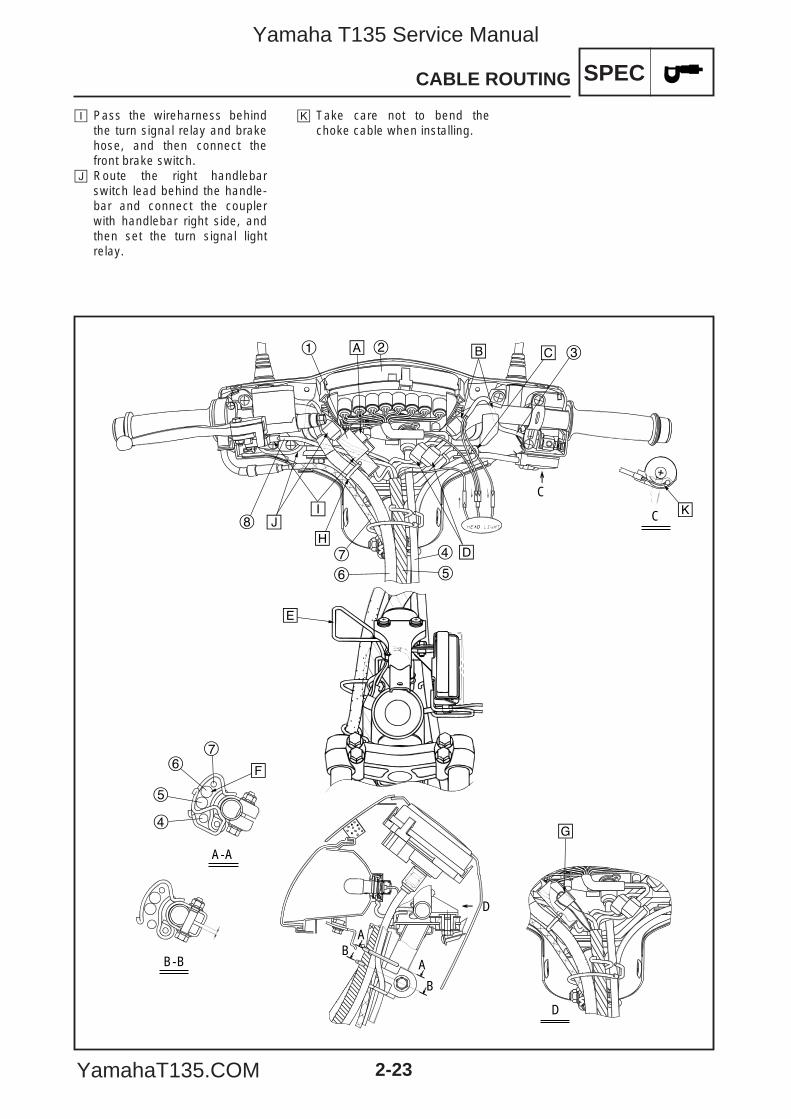
CABLE ROUTING1 Turn signal light relay2 Meter assembly3 Left handlebar switch lead4 Speedometer cable5 Wireharness6 Brake hose7 Throttle cable8 Front brake light switch lead
å Install the turn signal relayonto the bracket.
∫ Connect the left handlebarswitch lead coupler in front ofthe handlebar left.
ç Pass through the choke cableinto the wireharness.
∂ Connect the couplers in frontof the handlebar left side.
´ Do not pass the brake hoseinto the bracket.
ƒ Pass through into the wireguide, follow the routing order.Brake hose, throttle cable andwireharness.
© Hook the strap of the wirehar-ness onto the bracket.
˙ Pass through the brake hoseinto the wire guide on the han-dlebar bracket.
å ∫ ç
∂
ƒ
©
˙
ˆ∆
B
B
A-A
C
C
B-B A
A
1 2 3
4
5
67
4
56
7
8
´
D
D
˚
5YP-F8197-E0_2_1 05.6.27 19:46 Page 22
Yamaha T135 Service Manual
YamahaT135.COM
SPEC
2-23
CABLE ROUTING
ˆ Pass the wireharness behindthe turn signal relay and brakehose, and then connect thefront brake switch.
∆ Route the right handlebarswitch lead behind the handle-bar and connect the couplerwith handlebar right side, andthen set the turn signal lightrelay.
˚ Take care not to bend thechoke cable when installing.
å ∫ ç
∂
ƒ
©
˙
ˆ∆
B
B
A-A
C
C
B-B A
A
1 2 3
4
5
67
4
56
7
8
´
D
D
˚
5YP-F8197-E0_2_1 05.6.27 19:46 Page 23
Yamaha T135 Service Manual
YamahaT135.COM
SPEC
2-24
CABLE ROUTING
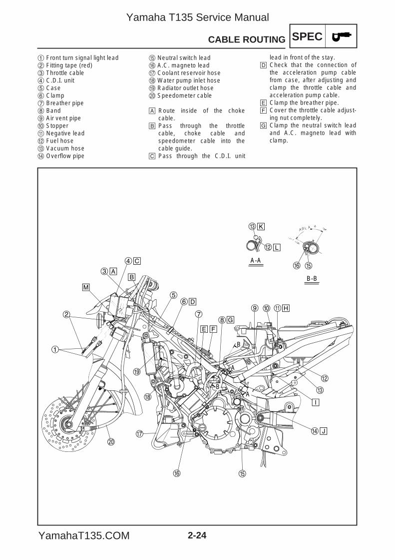
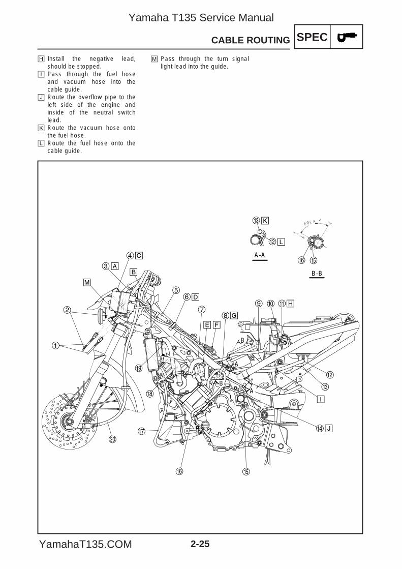
1 Front turn signal light lead2 Fitting tape (red)3 Throttle cable4 C.D.I. unit5 Case6 Clamp7 Breather pipe8 Band9 Air vent pipe0 Stopperq Negative leadw Fuel hosee Vacuum hoser Overflow pipe
t Neutral switch leady A.C. magneto leadu Coolant reservoir hosei Water pump inlet hoseo Radiator outlet hosep Speedometer cable
å Route inside of the chokecable.
∫ Pass through the throttlecable, choke cable andspeedometer cable into thecable guide.
ç Pass through the C.D.I. unit
lead in front of the stay.∂ Check that the connection of
the acceleration pump cablefrom case, after adjusting andclamp the throttle cable andacceleration pump cable.
´ Clamp the breather pipe.ƒ Cover the throttle cable adjust-
ing nut completely.© Clamp the neutral switch lead
and A.C. magneto lead withclamp.
å∫
ç
∂
´ƒ
©
˙
ˆ
∆
˚
¬
B
BA
A
A-A
B-B
1
2
3
4
56
78
9 0 q
w
w
e
e
r
y
y
t
t
u
i
p
o
µ
5YP-F8197-E0_2_1 05.6.27 19:46 Page 24
Yamaha T135 Service Manual
YamahaT135.COM
SPEC
2-25
CABLE ROUTING
å∫
ç
∂
´ƒ
©
˙
ˆ
∆
˚
¬
B
BA
A
A-A
B-B
1
2
3
4
56
78
9 0 q
w
w
e
e
r
y
y
t
t
u
i
p
o
µ
˙ Install the negative lead,should be stopped.
ˆ Pass through the fuel hoseand vacuum hose into thecable guide.
∆ Route the overflow pipe to theleft side of the engine andinside of the neutral switchlead.
˚ Route the vacuum hose ontothe fuel hose.
¬ Route the fuel hose onto thecable guide.
µ Pass through the turn signallight lead into the guide.
5YP-F8197-E0_2_1 05.6.27 19:46 Page 25
Yamaha T135 Service Manual
YamahaT135.COM
SPEC
2-26
CABLE ROUTING
å ∫ ç
∂
´
ƒ
©
˙
ˆ
∆
˚
1 2 3
4
4
5
5
5
6
6
7
8
9
0
q
we
r
t
A
A
B B
C
A-A B-B
C
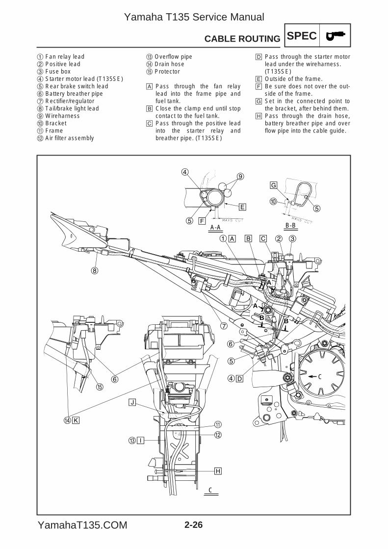
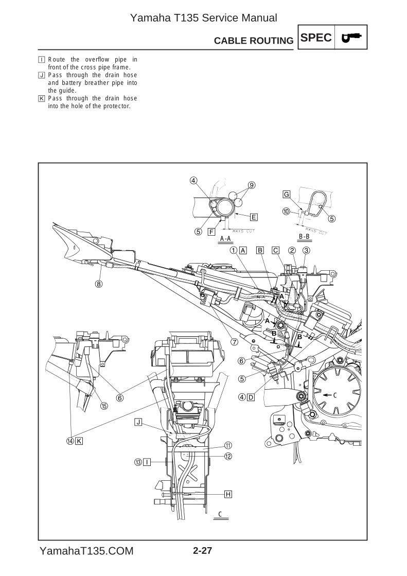
1 Fan relay lead2 Positive lead3 Fuse box4 Starter motor lead (T135SE)5 Rear brake switch lead6 Battery breather pipe7 Rectifier/regulator8 Tail/brake light lead9 Wireharness0 Bracketq Framew Air filter assembly
e Overflow piper Drain hoset Protector
å Pass through the fan relaylead into the frame pipe andfuel tank.
∫ Close the clamp end until stopcontact to the fuel tank.
ç Pass through the positive leadinto the starter relay andbreather pipe. (T135SE)
∂ Pass through the starter motorlead under the wireharness.(T135SE)
´ Outside of the frame.ƒ Be sure does not over the out-
side of the frame.© Set in the connected point to
the bracket, after behind them.˙ Pass through the drain hose,
battery breather pipe and overflow pipe into the cable guide.
5YP-F8197-E0_2_1 05.6.27 19:46 Page 26
Yamaha T135 Service Manual
YamahaT135.COM
SPEC
2-27
CABLE ROUTING
å ∫ ç
∂
´
ƒ
©
˙
ˆ
∆
˚
1 2 3
4
4
5
5
5
6
6
7
8
9
0
q
we
r
t
A
A
B B
C
A-A B-B
C
ˆ Route the overflow pipe infront of the cross pipe frame.
∆ Pass through the drain hoseand battery breather pipe intothe guide.
˚ Pass through the drain hoseinto the hole of the protector.
5YP-F8197-E0_2_1 05.6.27 19:46 Page 27
Yamaha T135 Service Manual
YamahaT135.COM
SPECCABLE ROUTING
2-28
å
∫
ç
∂
´
ƒ
© ˙ ˆ
∆
˚
¬
A
A
B
B
A-A
1
2
34
56
7
8
9
0
q w e
r
C
C
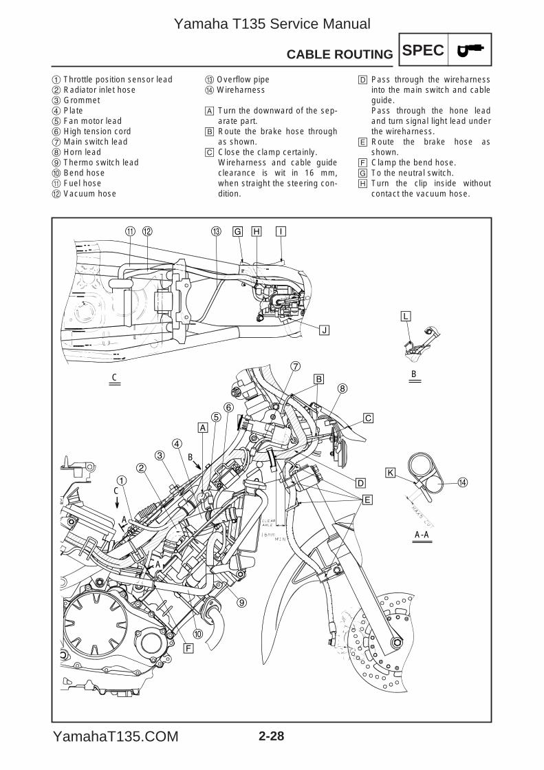
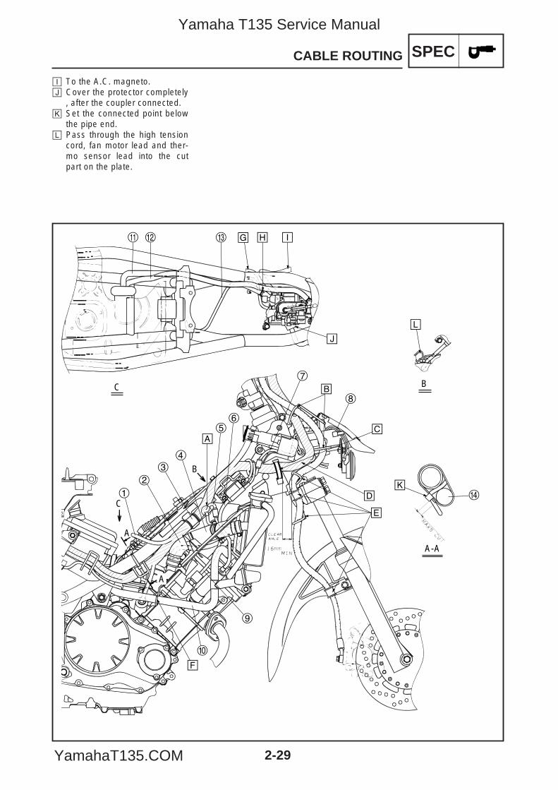
1 Throttle position sensor lead2 Radiator inlet hose3 Grommet4 Plate5 Fan motor lead6 High tension cord7 Main switch lead8 Horn lead9 Thermo switch lead0 Bend hoseq Fuel hosew Vacuum hose
e Overflow piper Wireharness
å Turn the downward of the sep-arate part.
∫ Route the brake hose throughas shown.
ç Close the clamp certainly.Wireharness and cable guideclearance is wit in 16 mm,when straight the steering con-dition.
∂ Pass through the wireharnessinto the main switch and cableguide.Pass through the hone leadand turn signal light lead underthe wireharness.
´ Route the brake hose asshown.
ƒ Clamp the bend hose.© To the neutral switch.˙ Turn the clip inside without
contact the vacuum hose.
5YP-F8197-E0_2_1 05.6.27 19:46 Page 28
Yamaha T135 Service Manual
YamahaT135.COM
SPECCABLE ROUTING
2-29
å
∫
ç
∂
´
ƒ
© ˙ ˆ
∆
˚
¬
A
A
B
B
A-A
1
2
34
56
7
8
9
0
q w e
r
C
C
ˆ To the A.C. magneto.∆ Cover the protector completely
, after the coupler connected.˚ Set the connected point below
the pipe end.¬ Pass through the high tension
cord, fan motor lead and ther-mo sensor lead into the cutpart on the plate.
5YP-F8197-E0_2_1 05.6.27 19:46 Page 29
Yamaha T135 Service Manual
YamahaT135.COM
SPECCABLE ROUTING
2-30
å
∫
ç
∂
´
ƒ
1
2
3
4
5
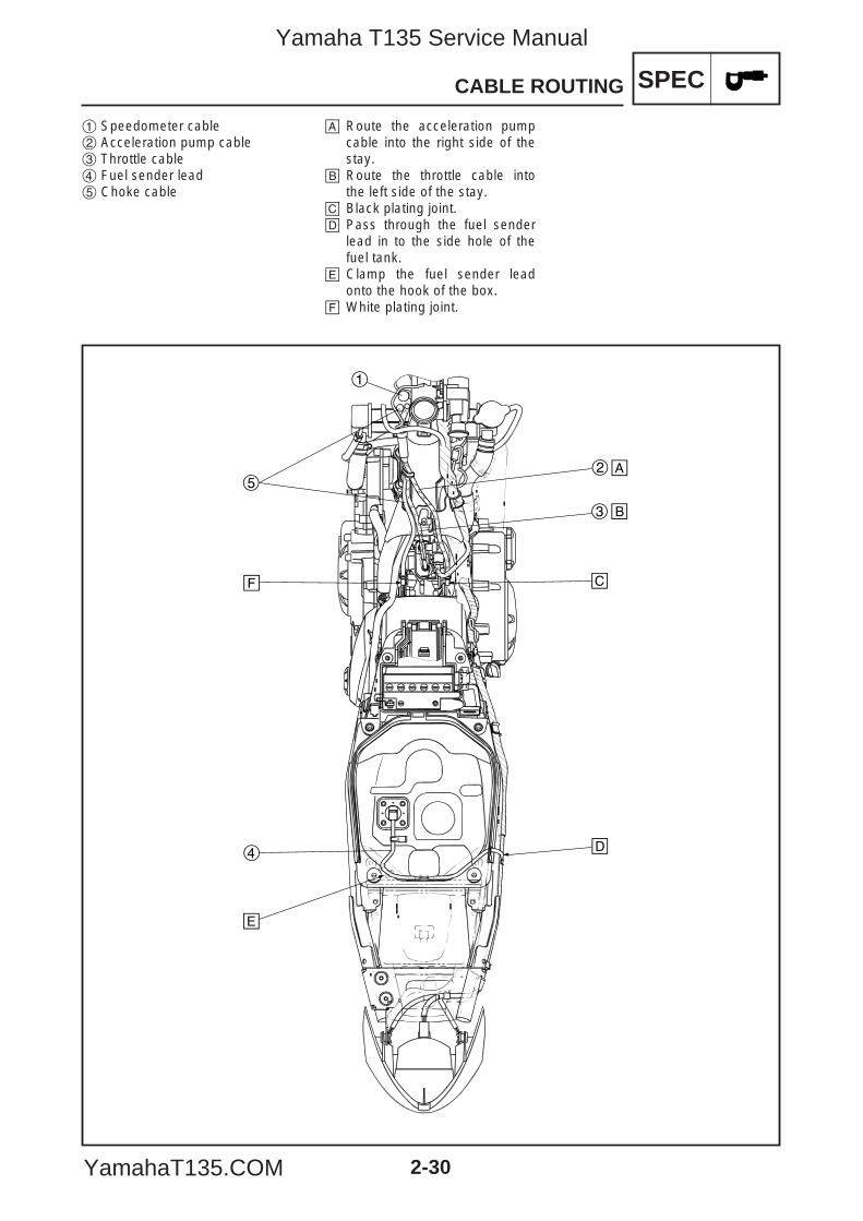
1 Speedometer cable2 Acceleration pump cable3 Throttle cable4 Fuel sender lead5 Choke cable
å Route the acceleration pumpcable into the right side of thestay.
∫ Route the throttle cable intothe left side of the stay.
ç Black plating joint.∂ Pass through the fuel sender
lead in to the side hole of thefuel tank.
´ Clamp the fuel sender leadonto the hook of the box.
ƒ White plating joint.
5YP-F8197-E0_2_1 05.6.27 19:46 Page 30
Yamaha T135 Service Manual
YamahaT135.COM
CHKADJ
CHAPTER 3PERIODIC CHECKS AND ADJUSTMENTS
INTRODUCTION .................................................................................................... 3-1
PERIODIC MAINTENANCE AND LUBRICATION INTERVALS ............................ 3-1
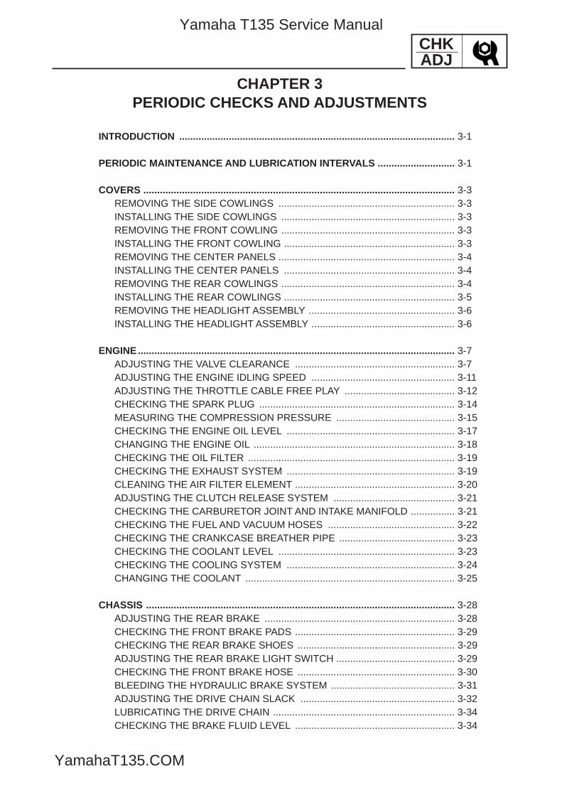
COVERS ................................................................................................................. 3-3REMOVING THE SIDE COWLINGS ................................................................ 3-3INSTALLING THE SIDE COWLINGS ............................................................... 3-3REMOVING THE FRONT COWLING ............................................................... 3-3INSTALLING THE FRONT COWLING .............................................................. 3-3REMOVING THE CENTER PANELS ................................................................ 3-4INSTALLING THE CENTER PANELS .............................................................. 3-4REMOVING THE REAR COWLINGS ............................................................... 3-4INSTALLING THE REAR COWLINGS .............................................................. 3-5REMOVING THE HEADLIGHT ASSEMBLY ..................................................... 3-6INSTALLING THE HEADLIGHT ASSEMBLY .................................................... 3-6
ENGINE................................................................................................................... 3-7ADJUSTING THE VALVE CLEARANCE .......................................................... 3-7ADJUSTING THE ENGINE IDLING SPEED .................................................... 3-11ADJUSTING THE THROTTLE CABLE FREE PLAY ........................................ 3-12CHECKING THE SPARK PLUG ....................................................................... 3-14MEASURING THE COMPRESSION PRESSURE ........................................... 3-15CHECKING THE ENGINE OIL LEVEL ............................................................. 3-17CHANGING THE ENGINE OIL ......................................................................... 3-18CHECKING THE OIL FILTER ........................................................................... 3-19CHECKING THE EXHAUST SYSTEM ............................................................. 3-19CLEANING THE AIR FILTER ELEMENT .......................................................... 3-20ADJUSTING THE CLUTCH RELEASE SYSTEM ............................................ 3-21CHECKING THE CARBURETOR JOINT AND INTAKE MANIFOLD ................ 3-21CHECKING THE FUEL AND VACUUM HOSES .............................................. 3-22CHECKING THE CRANKCASE BREATHER PIPE .......................................... 3-23CHECKING THE COOLANT LEVEL ................................................................ 3-23CHECKING THE COOLING SYSTEM ............................................................. 3-24CHANGING THE COOLANT ............................................................................ 3-25
CHASSIS ................................................................................................................ 3-28ADJUSTING THE REAR BRAKE ..................................................................... 3-28CHECKING THE FRONT BRAKE PADS .......................................................... 3-29CHECKING THE REAR BRAKE SHOES ......................................................... 3-29ADJUSTING THE REAR BRAKE LIGHT SWITCH ........................................... 3-29CHECKING THE FRONT BRAKE HOSE ......................................................... 3-30BLEEDING THE HYDRAULIC BRAKE SYSTEM ............................................. 3-31ADJUSTING THE DRIVE CHAIN SLACK ........................................................ 3-32LUBRICATING THE DRIVE CHAIN .................................................................. 3-34CHECKING THE BRAKE FLUID LEVEL .......................................................... 3-34
5YP-F8197-E0_3_1 05.6.27 20:32 Page A
Yamaha T135 Service Manual
YamahaT135.COM
CHKADJ
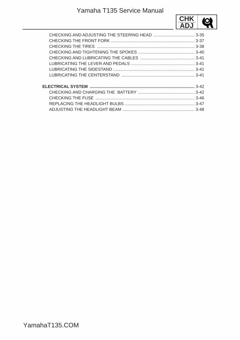
CHECKING AND ADJUSTING THE STEERING HEAD ................................... 3-35CHECKING THE FRONT FORK ....................................................................... 3-37CHECKING THE TIRES ................................................................................... 3-38CHECKING AND TIGHTENING THE SPOKES ................................................ 3-40CHECKING AND LUBRICATING THE CABLES .............................................. 3-41LUBRICATING THE LEVER AND PEDALS ...................................................... 3-41LUBRICATING THE SIDESTAND ..................................................................... 3-41LUBRICATING THE CENTERSTAND .............................................................. 3-41
ELECTRICAL SYSTEM ......................................................................................... 3-42CHECKING AND CHARGING THE BATTERY ................................................ 3-42CHECKING THE FUSE .................................................................................... 3-46REPLACING THE HEADLIGHT BULBS ........................................................... 3-47ADJUSTING THE HEADLIGHT BEAM ............................................................. 3-48
5YP-F8197-E0_3_1 05.6.27 20:32 Page B
Yamaha T135 Service Manual
YamahaT135.COM
CHKADJ
INTRODUCTION/PERIODIC MAINTENANCE AND LUBRICATION INTERVALS
EAS00036
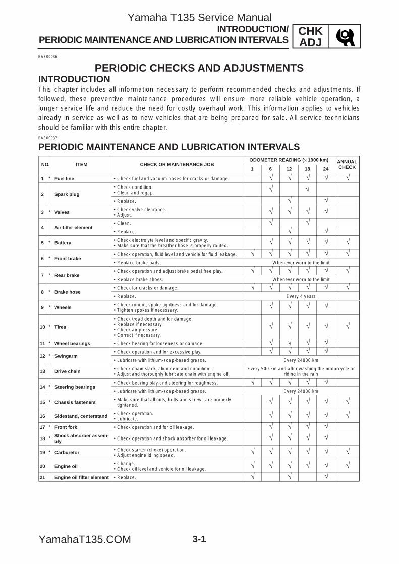
PERIODIC CHECKS AND ADJUSTMENTSINTRODUCTIONThis chapter includes all information necessary to perform recommended checks and adjustments. Iffollowed, these preventive maintenance procedures will ensure more reliable vehicle operation, alonger service life and reduce the need for costly overhaul work. This information applies to vehiclesalready in service as well as to new vehicles that are being prepared for sale. All service techniciansshould be familiar with this entire chapter.EAS00037
PERIODIC MAINTENANCE AND LUBRICATION INTERVALS
3-1
NO. ITEM CHECK OR MAINTENANCE JOBODOMETER READING (× 1000 km) ANNUAL
CHECK1 6 12 18 24
1 * Fuel line 9 Check fuel and vacuum hoses for cracks or damage. √ √ √
2 Spark plug9 Check condition.9 Clean and regap. √9 Replace. √
3 * Valves 9 Check valve clearance.9 Adjust. √ √
4 Air filter element9 Clean. √9 Replace. √
5 * Battery 9 Check electrolyte level and specific gravity.9 Make sure that the breather hose is properly routed. √ √ √
6 * Front brake9 Check operation, fluid level and vehicle for fluid leakage. √ √ √ √9 Replace brake pads. Whenever worn to the limit
7 * Rear brake9 Check operation and adjust brake pedal free play. √ √ √ √9 Replace brake shoes. Whenever worn to the limit
8 * Brake hose9 Check for cracks or damage. √ √ √9 Replace. Every 4 years
9 * Wheels 9 Check runout, spoke tightness and for damage.9 Tighten spokes if necessary.
√ √
10 * Tires
9 Check tread depth and for damage.9 Replace if necessary.9 Check air pressure.9 Correct if necessary.
√ √ √
11 * Wheel bearings 9 Check bearing for looseness or damage. √ √
12 * Swingarm9 Check operation and for excessive play. √ √9 Lubricate with lithium-soap-based grease. Every 24000 km
13 Drive chain 9 Check chain slack, alignment and condition.9 Adjust and thoroughly lubricate chain with engine oil.
Every 500 km and after washing the motorcycle or riding in the rain
14 * Steering bearings9 Check bearing play and steering for roughness. √ √ √9 Lubricate with lithium-soap-based grease. Every 24000 km
15 * Chassis fasteners 9 Make sure that all nuts, bolts and screws are properly tightened. √ √ √
16 Sidestand, centerstand 9 Check operation.9 Lubricate. √ √ √
17 * Front fork 9 Check operation and for oil leakage. √ √18 * Shock absorber assem-
bly 9 Check operation and shock absorber for oil leakage. √ √
19 * Carburetor 9 Check starter (choke) operation.9 Adjust engine idling speed. √ √ √ √
20 Engine oil 9 Change.9 Check oil level and vehicle for oil leakage. √ √ √ √
21 Engine oil filter element 9 Replace. √
√
√
√
√
√√ √
√
√ √√
√ √√
√
√ √√
√ √
√ √ √
√ √
√ √
√ √√ √
√ √
√ √√ √√ √
√ √
Yamaha T135 Service Manual
YamahaT135.COM
CHKADJ
3-2
PERIODIC MAINTENANCE AND LUBRICATION INTERVALS
EAU18660
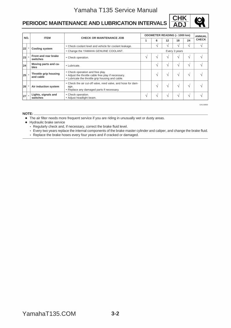
NOTE:7 The air filter needs more frequent service if you are riding in unusually wet or dusty areas.7 Hydraulic brake service
9 Regularly check and, if necessary, correct the brake fluid level.9 Every two years replace the internal components of the brake master cylinder and caliper, and change the brake fluid.9 Replace the brake hoses every four years and if cracked or damaged.
22 * Cooling system9 Check coolant level and vehicle for coolant leakage. √ √ √9 Change the YAMAHA GENUINE COOLANT. Every 3 years
23 * Front and rear brake switches 9 Check operation. √ √ √ √
24 Moving parts and ca-bles 9 Lubricate. √ √ √
25 * Throttle grip housing and cable
9 Check operation and free play.9 Adjust the throttle cable free play if necessary.9 Lubricate the throttle grip housing and cable.
√ √ √
26 * Air induction system9 Check the air cut-off valve, reed valve, and hose for dam-
age.9 Replace any damaged parts if necessary.
√ √ √
27 * Lights, signals and switches
9 Check operation.9 Adjust headlight beam. √ √ √ √
NO. ITEM CHECK OR MAINTENANCE JOBODOMETER READING (× 1000 km) ANNUAL
CHECK1 6 12 18 24
√ √
√ √
√ √
√ √
√ √
√ √
5YP-F8197-E0_3_1 05.6.27 20:32 Page 2
Yamaha T135 Service Manual
YamahaT135.COM
3-3
CHKADJCOVERS
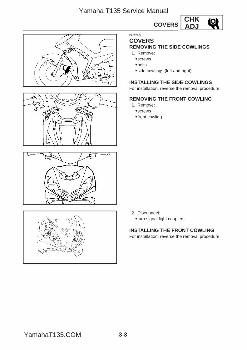
2. Disconnect:9turn signal light couplers
INSTALLING THE FRONT COWLINGFor installation, reverse the removal procedure.
EASF0004
COVERSREMOVING THE SIDE COWLINGS1. Remove:9screws9bolts9side cowlings (left and right)
INSTALLING THE SIDE COWLINGSFor installation, reverse the removal procedure.
REMOVING THE FRONT COWLING1. Remove:9screws9front cowling
5YP-F8197-E0_3_1 05.6.27 20:32 Page 3
Yamaha T135 Service Manual
YamahaT135.COM
3-4
2
3
1
1
1
1
CHKADJCOVERS
1
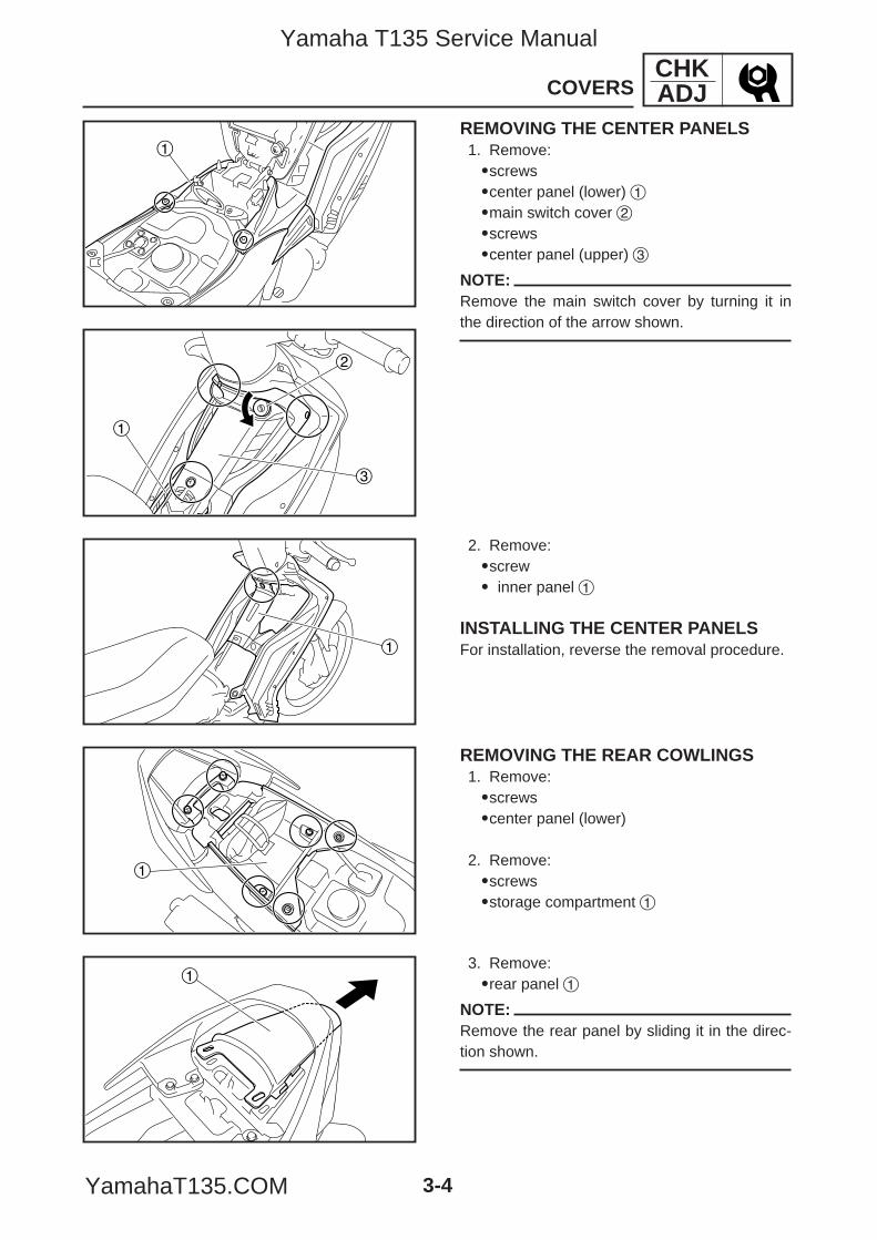
3. Remove:9rear panel 1
NOTE:Remove the rear panel by sliding it in the direc-tion shown.
REMOVING THE CENTER PANELS1. Remove:9screws9center panel (lower) 19main switch cover 29screws9center panel (upper) 3
NOTE:Remove the main switch cover by turning it inthe direction of the arrow shown.
2. Remove:9screw9 inner panel 1
INSTALLING THE CENTER PANELSFor installation, reverse the removal procedure.
REMOVING THE REAR COWLINGS1. Remove:9screws9center panel (lower)
2. Remove:9screws9storage compartment 1
5YP-F8197-E0_3_1 05.6.27 20:32 Page 4
Yamaha T135 Service Manual
YamahaT135.COM
3-5
2
1
1
2
CHKADJCOVERS
1
2
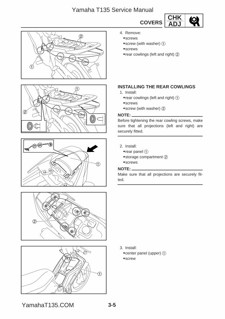
4. Remove:9screws9screw (with washer) 19screws9rear cowlings (left and right) 2
INSTALLING THE REAR COWLINGS1. Install:9rear cowlings (left and right) 19screws9screw (with washer) 2
NOTE:Before tightening the rear cowling screws, makesure that all projections (left and right) aresecurely fitted.
2. Install:9rear panel 19storage compartment 29screws
NOTE:Make sure that all projections are securely fit-ted.
1
3. Install:9center panel (upper) 19screw
5YP-F8197-E0_3_1 05.6.27 20:32 Page 5
Yamaha T135 Service Manual
YamahaT135.COM
1
1
CHKADJCOVERS
3-6
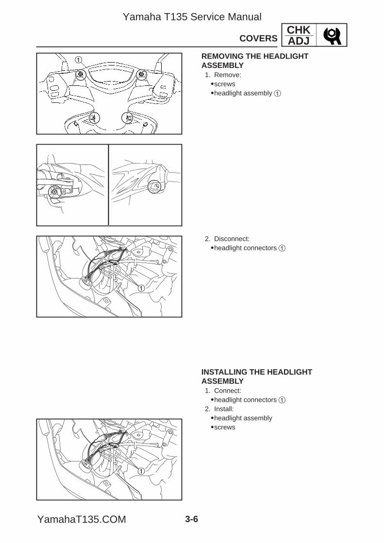
INSTALLING THE HEADLIGHTASSEMBLY1. Connect:9headlight connectors 1
2. Install:9headlight assembly9screws
2. Disconnect:9headlight connectors 1
1 REMOVING THE HEADLIGHTASSEMBLY1. Remove:9screws9headlight assembly 1
5YP-F8197-E0_3_1 05.6.27 20:32 Page 6
Yamaha T135 Service Manual
YamahaT135.COM
EAS00049
ENGINEADJUSTING THE VALVE CLEARANCEThe following procedure applies to all of thevalves.
NOTE:9Valve clearance adjustment should be madeon a cold engine, at room temperature.9When the valve clearance is to be measuredor adjusted, the piston must be at top deadcenter (TDC) on the compression stroke.
1. Remove:9side cowlings (left and right)9front cowlingRefer to “REMOVING THE SIDE COWL-INGS” AND “REMOVING THE FRONTCOWLING”.
CHKADJADJUSTING THE VALVE CLEARANCE
3-7
2. Drain:9cooling systemRefer to “CHANGING THE COOLANT”.
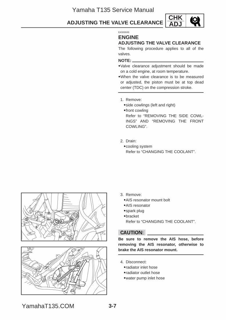
3. Remove:9AIS resonator mount bolt9AIS resonator9spark plug9bracketRefer to “CHANGING THE COOLANT”.
cCBe sure to remove the AIS hose, beforeremoving the AIS resonator, otherwise tobrake the AIS resonator mount.
4. Disconnect:9radiator inlet hose9radiator outlet hose9water pump inlet hose
5YP-F8197-E0_3_1 05.6.27 20:32 Page 7
Yamaha T135 Service Manual
YamahaT135.COM
1
2
a
b
CHKADJADJUSTING THE VALVE CLEARANCE
3-8
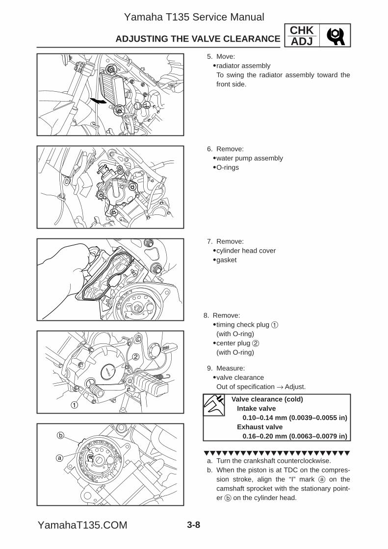
5. Move:9radiator assemblyTo swing the radiator assembly toward thefront side.
6. Remove:9water pump assembly9O-rings
7. Remove:9cylinder head cover9gasket
8. Remove:9timing check plug 1(with O-ring)9center plug 2(with O-ring)
9. Measure:9valve clearanceOut of specification → Adjust.
a. Turn the crankshaft counterclockwise.b. When the piston is at TDC on the compres-
sion stroke, align the “I” mark a on thecamshaft sprocket with the stationary point-er b on the cylinder head.
Valve clearance (cold)Intake valve
0.10–0.14 mm (0.0039–0.0055 in)Exhaust valve
0.16–0.20 mm (0.0063–0.0079 in)
5YP-F8197-E0_3_1 05.6.27 20:32 Page 8
Yamaha T135 Service Manual
YamahaT135.COM
CHKADJADJUSTING THE VALVE CLEARANCE
3-9
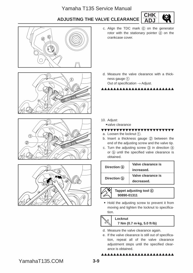
d. Measure the valve clearance with a thick-ness gauge 1Out of specification → Adjust.
cd
1
1
2
a
b
3
4
10. Adjust:9valve clearance
a. Loosen the locknut 1.b. Insert a thickness gauge 2 between the
end of the adjusting screw and the valve tip.c. Turn the adjusting screw 3 in direction a
or b until the specified valve clearance isobtained.
9 Hold the adjusting screw to prevent it frommoving and tighten the locknut to specifica-tion.
d. Measure the valve clearance again.e. If the valve clearance is still out of specifica-
tion, repeat all of the valve clearanceadjustment steps until the specified clear-ance is obtained.
Direction aaValve clearance is
increased.
Direction bbValve clearance is
decreased.
Tappet adjusting tool 4490890-01311
Locknut7 Nm (0.7 m·kg, 5.0 ft·lb)
c. Align the TDC mark c on the generatorrotor with the stationary pointer d on thecrankcase cover.
5YP-F8197-E0_3_1 05.6.27 20:32 Page 9
Yamaha T135 Service Manual
YamahaT135.COM
1
CHKADJADJUSTING THE VALVE CLEARANCE
3-10
11. Install:9O-ring9timing check plug(with O-ring)9center plug(with O-ring)
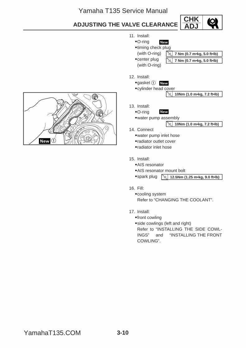
12. Install:9gasket 19cylinder head cover
13. Install:9O-ring9water pump assembly
14. Connect9water pump inlet hose9radiator outlet cover9radiator inlet hose
15. Install:9AIS resonator9AIS resonator mount bolt9spark plug
16. Fill:9cooling systemRefer to “CHANGING THE COOLANT”.
17. Install:9front cowling9side cowlings (left and right)Refer to “INSTALLING THE SIDE COWL-INGS” and “INSTALLING THE FRONTCOWLING”.
7 Nm (0.7 m•kg, 5.0 ft•lb)
7 Nm (0.7 m•kg, 5.0 ft•lb)
10Nm (1.0 m•kg, 7.2 ft•lb)
10Nm (1.0 m•kg, 7.2 ft•lb)
12.5Nm (1.25 m•kg, 9.0 ft•lb)
5YP-F8197-E0_3_1 05.6.27 20:32 Page 10
Yamaha T135 Service Manual
YamahaT135.COM
ab
2
1
CHKADJ
3-11
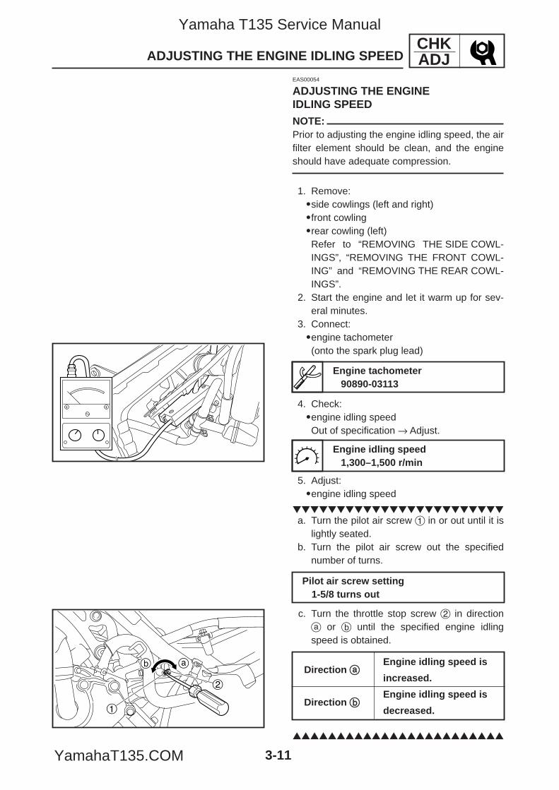
5. Adjust:9engine idling speed
a. Turn the pilot air screw 1 in or out until it is
lightly seated.b. Turn the pilot air screw out the specified
number of turns.
c. Turn the throttle stop screw 2 in directiona or b until the specified engine idlingspeed is obtained.
Pilot air screw setting1-5/8 turns out
ADJUSTING THE ENGINE IDLING SPEED
EAS00054
ADJUSTING THE ENGINEIDLING SPEEDNOTE:Prior to adjusting the engine idling speed, the airfilter element should be clean, and the engineshould have adequate compression.
1. Remove:9side cowlings (left and right)9front cowling 9rear cowling (left)Refer to “REMOVING THE SIDE COWL-INGS”, “REMOVING THE FRONT COWL-ING” and “REMOVING THE REAR COWL-INGS”.
2. Start the engine and let it warm up for sev-eral minutes.
3. Connect:9engine tachometer(onto the spark plug lead)
4. Check:9engine idling speedOut of specification → Adjust.
Engine tachometer90890-03113
Engine idling speed1,300–1,500 r/min
Direction aaEngine idling speed is
increased.
Direction bbEngine idling speed is
decreased.
5YP-F8197-E0_3_1 05.6.27 20:32 Page 11
Yamaha T135 Service Manual
YamahaT135.COM
CHKADJ
3-12
6. Adjust:9throttle cable free playRefer to “ADJUSTING THE THROTTLECABLE FREE PLAY”.
7. Install:9rear cowling (left)9front cowling9side cowlings (left and right)Refer to “INSTALLING THE REAR COWL-INGS”, “INSTALLING THE FRONT COWL-ING” and “INSTALLING THE REAR COWL-INGS”.
ADJUSTING THE ENGINE IDLING SPEED/ADJUSTING THE THROTTLE CABLE FREE PLAY
Throttle cable free play (at the flange of the throttle grip)
3–7 mm (0.12–0.28 in)
a
EAS00058
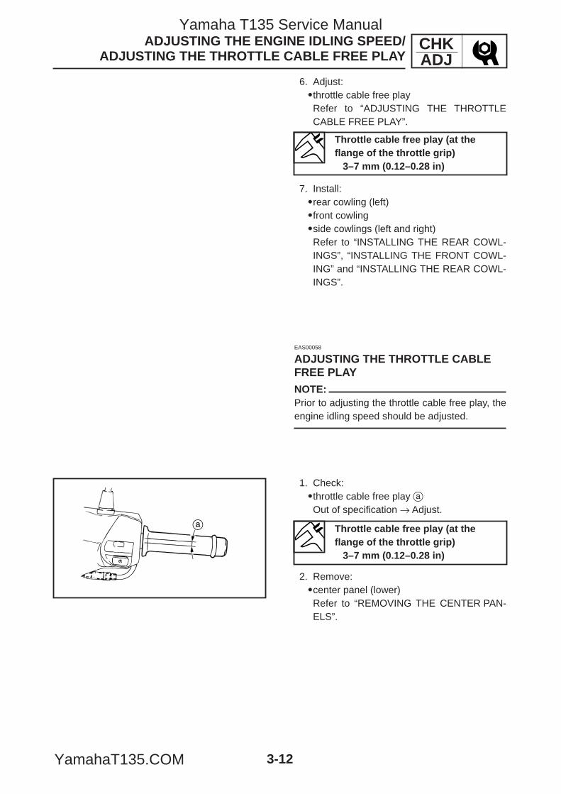
ADJUSTING THE THROTTLE CABLEFREE PLAYNOTE:Prior to adjusting the throttle cable free play, theengine idling speed should be adjusted.
1. Check:9throttle cable free play aOut of specification → Adjust.
2. Remove:9center panel (lower)Refer to “REMOVING THE CENTER PAN-ELS”.
Throttle cable free play (at theflange of the throttle grip)
3–7 mm (0.12–0.28 in)
5YP-F8197-E0_3_1 05.6.27 20:32 Page 12
Yamaha T135 Service Manual
YamahaT135.COM
CHKADJ
3-13
ADJUSTING THE THROTTLE CABLE FREE PLAY
a
b
1
2
1
2
a
b
c
de
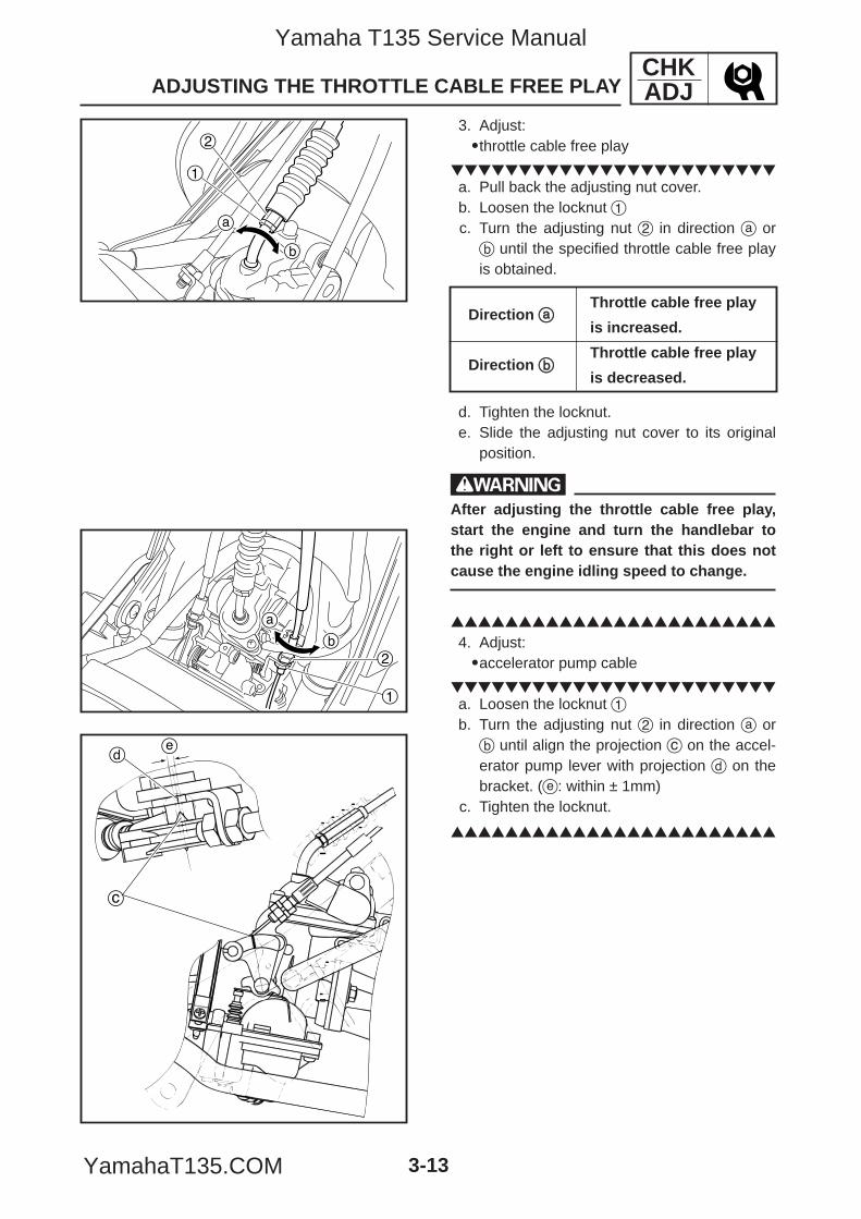
3. Adjust:9throttle cable free play
a. Pull back the adjusting nut cover.b. Loosen the locknut 1c. Turn the adjusting nut 2 in direction a orb until the specified throttle cable free playis obtained.
d. Tighten the locknut.e. Slide the adjusting nut cover to its original
position.
wAfter adjusting the throttle cable free play,start the engine and turn the handlebar tothe right or left to ensure that this does notcause the engine idling speed to change.
4. Adjust:9accelerator pump cable
a. Loosen the locknut 1b. Turn the adjusting nut 2 in direction a orb until align the projection c on the accel-erator pump lever with projection d on thebracket. (e: within ± 1mm)
c. Tighten the locknut.
Direction aaThrottle cable free play
is increased.
Direction bbThrottle cable free play
is decreased.
5YP-F8197-E0_3_1 05.6.27 20:32 Page 13
Yamaha T135 Service Manual
YamahaT135.COM
CHKADJ
3-14
1
2
a
CHECKING THE SPARK PLUG
4. Check:9spark plug typeIncorrect → Change.
EAS00060
CHECKING THE SPARK PLUG1. Remove:9side cowling (right)Refer to “REMOVING THE SIDE COWL-INGS”.9AIS resonator
cCBe sure to remove the AIS hose, beforeremoving the AIS resonator, otherwise tobrake the AIS resonator mount.
2. Disconnect:9spark plug cap
3. Remove:9spark plug
cCBefore removing the spark plug, blow awayany dirt accumulated in the spark plug wellwith compressed air to prevent it from fallinginto the cylinder.
Spark plug type (manufacturer)CPR8EA-9 (NGK)
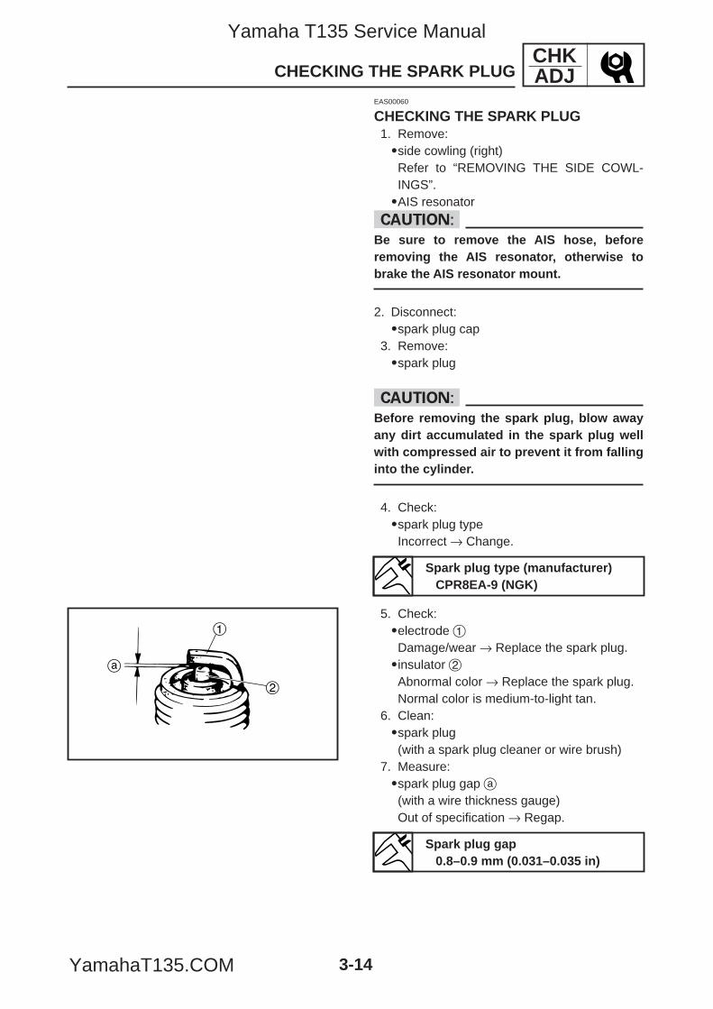
5. Check:9electrode 1Damage/wear → Replace the spark plug.9insulator 2Abnormal color → Replace the spark plug.Normal color is medium-to-light tan.
6. Clean:9spark plug(with a spark plug cleaner or wire brush)
7. Measure:9spark plug gap a(with a wire thickness gauge)Out of specification → Regap.
Spark plug gap0.8–0.9 mm (0.031–0.035 in)
5YP-F8197-E0_3_1 05.6.27 20:32 Page 14
Yamaha T135 Service Manual
YamahaT135.COM
CHKADJ
3-15
CHECKING THE SPARK PLUG/MEASURING THE COMPRESSION PRESSURE
EAS00067
MEASURING THE COMPRESSIONPRESSURENOTE:Insufficient compression pressure will result in aloss of performance.
1. Remove:9side cowling (right)Refer to “REMOVING THE SIDE COWL-ING”.
2. Measure:9valve clearanceOut of specification → AdjustRefer to “ADJUSTING THE VALVE CLEAR-ANCE”.
3. Start the engine, warm it up for several min-utes, and then turn it off.
4. Disconnect:9spark plug cap
5. Remove:9spark plug
cCBefore removing the spark plug, use com-pressed air to blow away any dirt accumulat-ed in the spark plug well to prevent it fromfalling into the cylinder.
8. Install:9spark plug
NOTE:Before installing the spark plug, clean the sparkplug and gasket surface.
9. Connect:9spark plug cap
10. Install:9AIS resonator9center panel (lower)Refer to “INSTALLING THE CENTER PAN-ELS”.
13 Nm (1.3 m•kg, 9.5 ft•lb)
5YP-F8197-E0_3_1 05.6.27 20:32 Page 15
Yamaha T135 Service Manual
YamahaT135.COM
CHKADJ
3-16
MEASURING THE COMPRESSION PRESSURE
a. Set the main switch to “ON”.b. With the throttle wide open and push the
“START” switch, then crank the engine untilthe reading on the compression gauge sta-bilizes.
wTo prevent sparking, ground the spark pluglead before cranking the engine.
c. If the compression pressure is above themaximum specification, check the cylinderhead, valve surfaces, and piston crown forcarbon deposits.Carbon deposits → Eliminate.
d. If the compression pressure is below theminimum specification, pour a teaspoonfulof engine oil into the spark plug bore andmeasure again.Refer to the following table.
Compression pressure
(with oil applied into the cylinder)Reading Diagnosis
Piston ring(s) wearHigher than with-
or damage →→out oil
Repair.Piston, valves, cyl-
Same as without inder head gasketoil or piston possibly
defective →→ Repair.
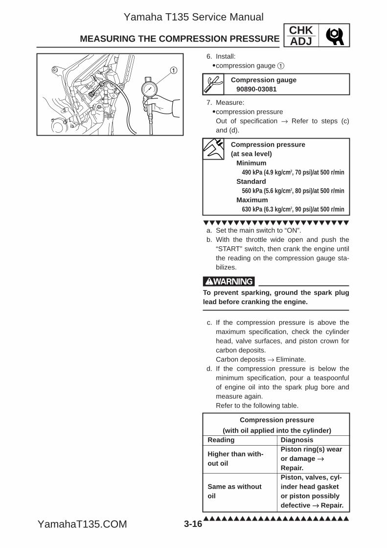
1
6. Install:9compression gauge 1
7. Measure:9compression pressureOut of specification → Refer to steps (c)and (d).
Compression gauge90890-03081
Compression pressure(at sea level)
Minimum490 kPa (4.9 kg/cm2, 70 psi)/at 500 r/min
Standard560 kPa (5.6 kg/cm2, 80 psi)/at 500 r/min
Maximum630 kPa (6.3 kg/cm2, 90 psi)/at 500 r/min
5YP-F8197-E0_3_1 05.6.27 20:32 Page 16
Yamaha T135 Service Manual
YamahaT135.COM
8. Install:9spark plug
9. Connect:9spark plug cap
10. Install:9side cowling (right)Refer to “INSTALLING THE SIDE COWL-INGS”.
1
ba
CHKADJ
3-17
MEASURING THE COMPRESSION PRESSURE/CHECKING THE ENGINE OIL LEVEL
EAS00070
CHECKING THE ENGINE OIL LEVEL1. Stand the vehicle on a level surface.
NOTE:Make sure the vehicle is upright.
2. Start the engine, warm it up for several min-utes, and then turn it off.
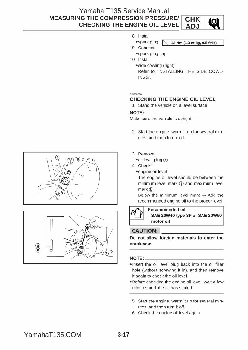
3. Remove:9oil level plug 1
4. Check:9engine oil levelThe engine oil level should be between theminimum level mark a and maximum levelmark b.Below the minimum level mark → Add therecommended engine oil to the proper level.
cCDo not allow foreign materials to enter thecrankcase.
NOTE:9Insert the oil level plug back into the oil fillerhole (without screwing it in), and then removeit again to check the oil level.9Before checking the engine oil level, wait a fewminutes until the oil has settled.
5. Start the engine, warm it up for several min-utes, and then turn it off.
6. Check the engine oil level again.
Recommended oilSAE 20W40 type SF or SAE 20W50motor oil
13 Nm (1.3 m•kg, 9.5 ft•lb)
5YP-F8197-E0_3_1 05.6.27 20:32 Page 17
Yamaha T135 Service Manual
YamahaT135.COM
1
CHKADJ
3-18
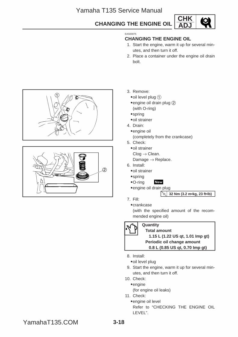
3. Remove:9oil level plug 19engine oil drain plug 2(with O-ring)9spring9oil strainer
4. Drain:9engine oil(completely from the crankcase)
5. Check:9oil strainerClog → Clean.Damage → Replace.
6. Install:9oil strainer9spring9O-ring9engine oil drain plug
7. Fill:9crankcase(with the specified amount of the recom-mended engine oil)
8. Install:9oil level plug
9. Start the engine, warm it up for several min-utes, and then turn it off.
10. Check:9engine(for engine oil leaks)
11. Check:9engine oil levelRefer to “CHECKING THE ENGINE OILLEVEL”.
CHANGING THE ENGINE OIL
QuantityTotal amount
1.15 L (1.22 US qt, 1.01 Imp gt)Periodic oil change amount
0.8 L (0.85 US qt, 0.70 Imp gt)
2
EAS00075
CHANGING THE ENGINE OIL1. Start the engine, warm it up for several min-
utes, and then turn it off.2. Place a container under the engine oil drain
bolt.
32 Nm (3.2 m•kg, 23 ft•lb)
5YP-F8197-E0_3_1 05.6.27 20:32 Page 18
Yamaha T135 Service Manual
YamahaT135.COM
2
1
CHKADJ
3-19
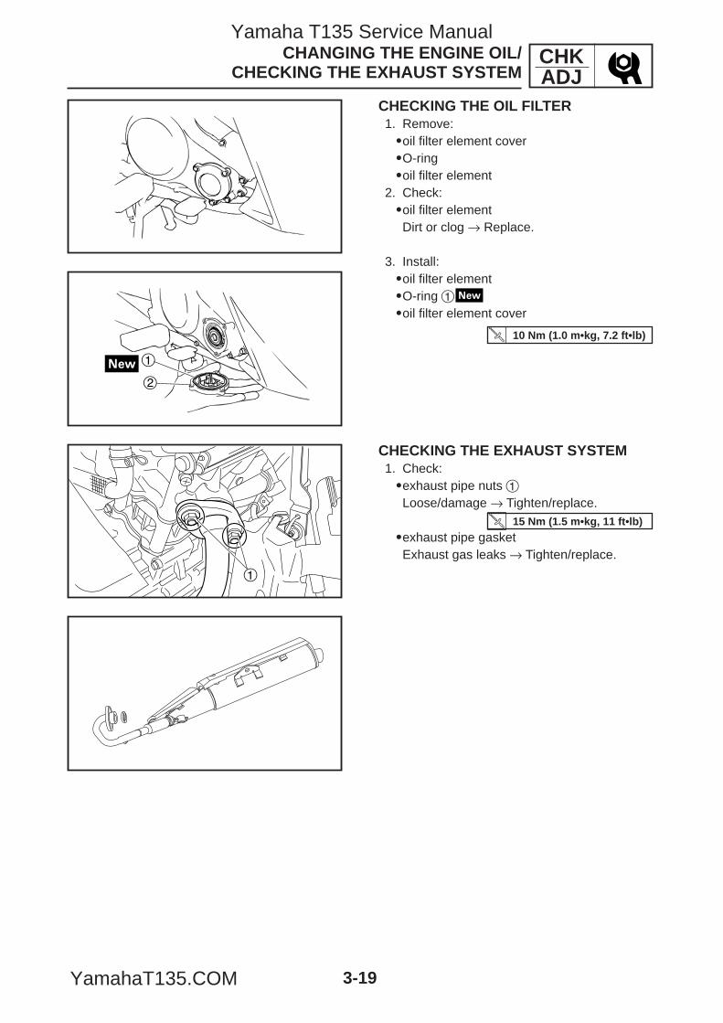
CHECKING THE OIL FILTER1. Remove:9oil filter element cover9O-ring9oil filter element
2. Check:9oil filter elementDirt or clog → Replace.
3. Install:9oil filter element9O-ring 19oil filter element cover
CHANGING THE ENGINE OIL/CHECKING THE EXHAUST SYSTEM
10 Nm (1.0 m•kg, 7.2 ft•lb)
1
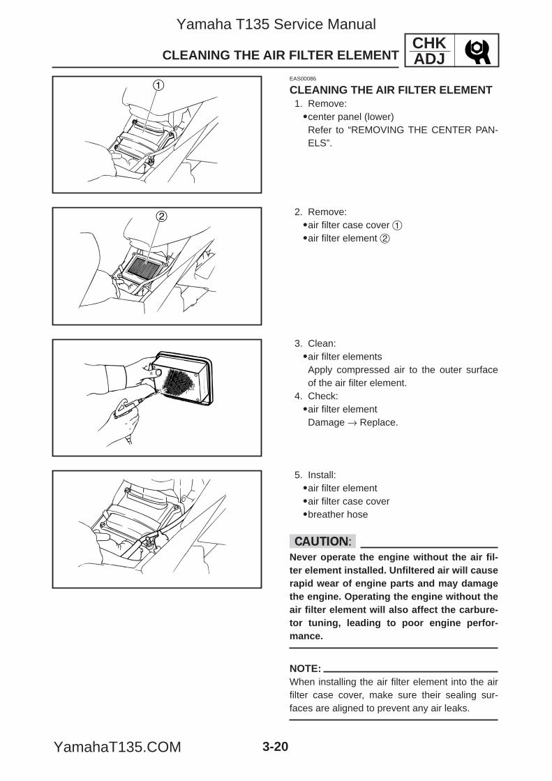
CHECKING THE EXHAUST SYSTEM1. Check:9exhaust pipe nuts 1Loose/damage → Tighten/replace.
9exhaust pipe gasketExhaust gas leaks → Tighten/replace.
15 Nm (1.5 m•kg, 11 ft•lb)
5YP-F8197-E0_3_1 05.6.27 20:32 Page 19
Yamaha T135 Service Manual
YamahaT135.COM
2
CHKADJ
3-20
CLEANING THE AIR FILTER ELEMENT
EAS00086
CLEANING THE AIR FILTER ELEMENT1. Remove:9center panel (lower)Refer to “REMOVING THE CENTER PAN-ELS”.
2. Remove:9air filter case cover 19air filter element 2
3. Clean:9air filter elementsApply compressed air to the outer surfaceof the air filter element.
4. Check:9air filter elementDamage → Replace.
5. Install:9air filter element9air filter case cover9breather hose
cCNever operate the engine without the air fil-ter element installed. Unfiltered air will causerapid wear of engine parts and may damagethe engine. Operating the engine without theair filter element will also affect the carbure-tor tuning, leading to poor engine perfor-mance.
NOTE:When installing the air filter element into the airfilter case cover, make sure their sealing sur-faces are aligned to prevent any air leaks.
1
5YP-F8197-E0_3_1 05.6.27 20:32 Page 20
Yamaha T135 Service Manual
YamahaT135.COM
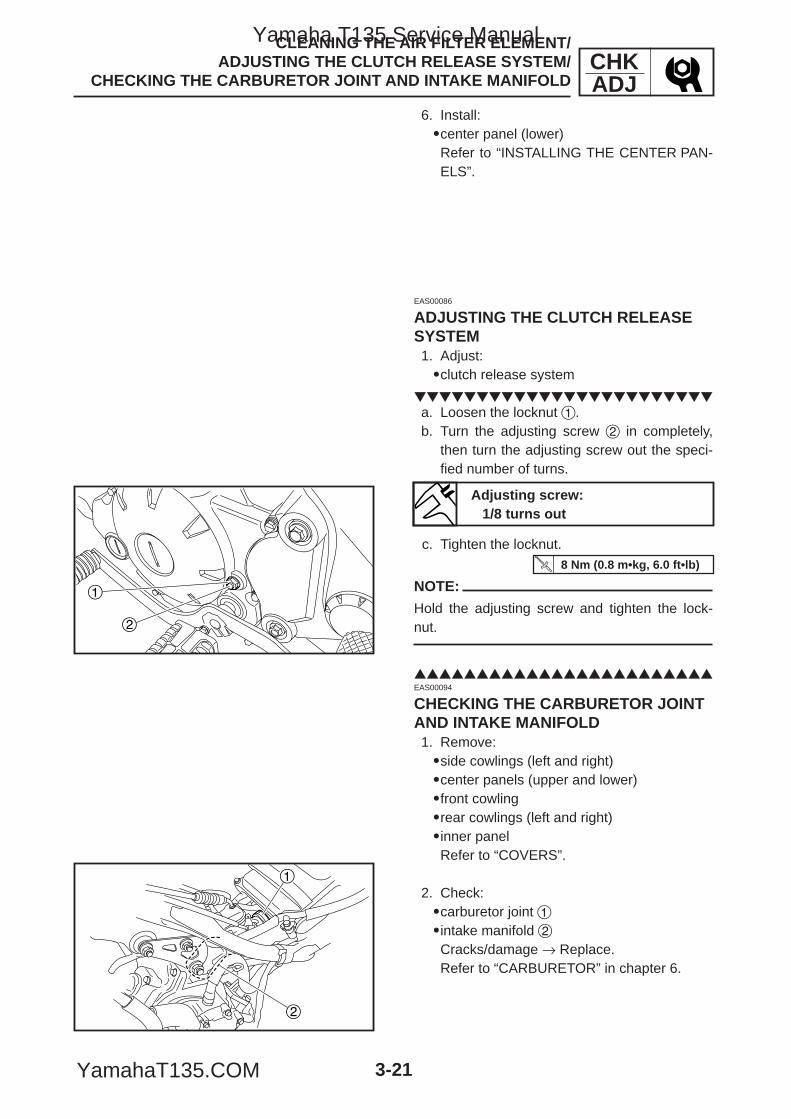
1
2
1
2
CHKADJ
3-21
CLEANING THE AIR FILTER ELEMENT/ ADJUSTING THE CLUTCH RELEASE SYSTEM/
CHECKING THE CARBURETOR JOINT AND INTAKE MANIFOLD
6. Install:9center panel (lower)Refer to “INSTALLING THE CENTER PAN-ELS”.
EAS00086
ADJUSTING THE CLUTCH RELEASESYSTEM1. Adjust:9clutch release system
a. Loosen the locknut 1.b. Turn the adjusting screw 2 in completely,
then turn the adjusting screw out the speci-fied number of turns.
c. Tighten the locknut.
NOTE:
Hold the adjusting screw and tighten the lock-nut.
Adjusting screw:1/8 turns out
8 Nm (0.8 m•kg, 6.0 ft•lb)
EAS00094
CHECKING THE CARBURETOR JOINTAND INTAKE MANIFOLD1. Remove:9side cowlings (left and right)9center panels (upper and lower)9front cowling9rear cowlings (left and right)9inner panelRefer to “COVERS”.
2. Check:9carburetor joint 19intake manifold 2Cracks/damage → Replace.Refer to “CARBURETOR” in chapter 6.
5YP-F8197-E0_3_1 05.6.27 20:32 Page 21
Yamaha T135 Service Manual
YamahaT135.COM
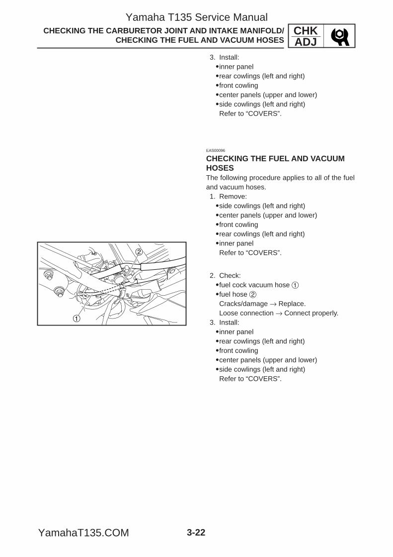
1
2
CHKADJ
3-22
CHECKING THE CARBURETOR JOINT AND INTAKE MANIFOLD/CHECKING THE FUEL AND VACUUM HOSES
3. Install:9inner panel9rear cowlings (left and right)9front cowling9center panels (upper and lower)9side cowlings (left and right)Refer to “COVERS”.
EAS00096
CHECKING THE FUEL AND VACUUMHOSESThe following procedure applies to all of the fueland vacuum hoses.1. Remove:9side cowlings (left and right)9center panels (upper and lower)9front cowling9rear cowlings (left and right)9inner panelRefer to “COVERS”.
2. Check:9fuel cock vacuum hose 19fuel hose 2Cracks/damage → Replace.Loose connection → Connect properly.
3. Install:9inner panel9rear cowlings (left and right)9front cowling9center panels (upper and lower)9side cowlings (left and right)Refer to “COVERS”.
5YP-F8197-E0_3_1 05.6.27 20:32 Page 22
Yamaha T135 Service Manual
YamahaT135.COM
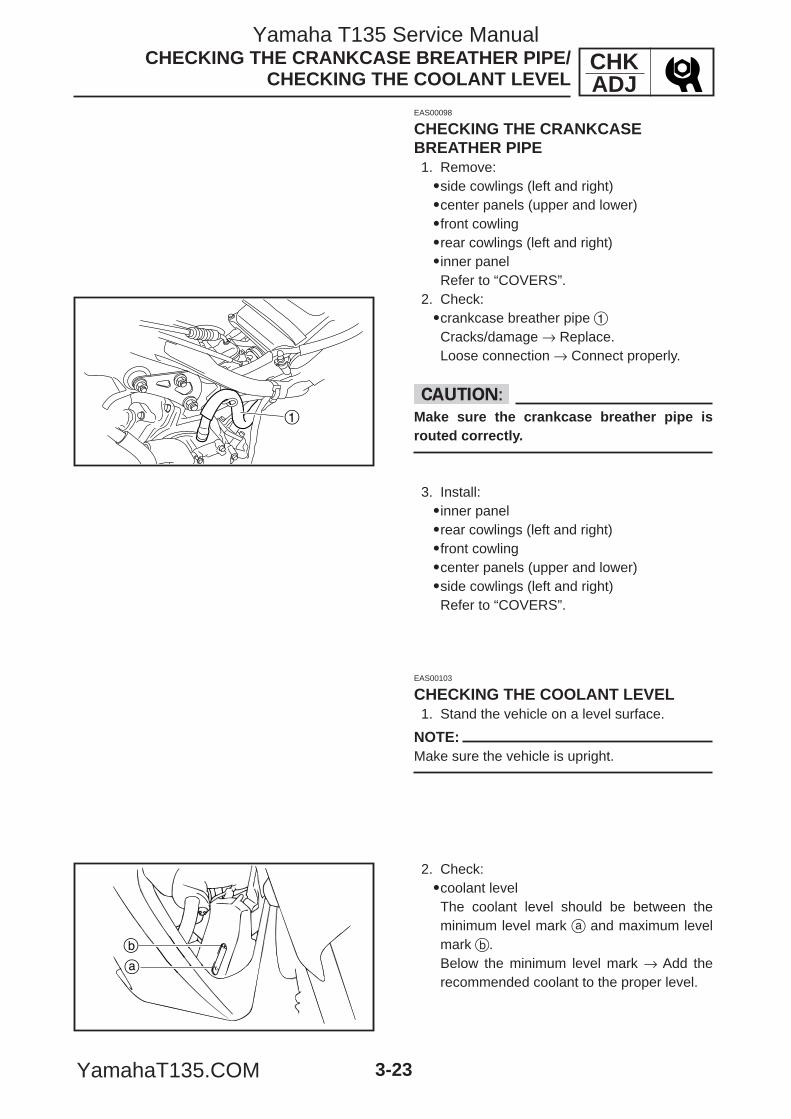
1
a
b
CHKADJ
3-23
CHECKING THE CRANKCASE BREATHER PIPE/CHECKING THE COOLANT LEVEL
EAS00098
CHECKING THE CRANKCASEBREATHER PIPE1. Remove:9side cowlings (left and right)9center panels (upper and lower)9front cowling9rear cowlings (left and right)9inner panelRefer to “COVERS”.
2. Check:9crankcase breather pipe 1Cracks/damage → Replace.Loose connection → Connect properly.
cCMake sure the crankcase breather pipe isrouted correctly.
EAS00103
CHECKING THE COOLANT LEVEL1. Stand the vehicle on a level surface.
NOTE:Make sure the vehicle is upright.
2. Check:9coolant levelThe coolant level should be between theminimum level mark a and maximum levelmark b.Below the minimum level mark → Add therecommended coolant to the proper level.
3. Install:9inner panel9rear cowlings (left and right)9front cowling9center panels (upper and lower)9side cowlings (left and right)Refer to “COVERS”.
5YP-F8197-E0_3_1 05.6.27 20:32 Page 23
Yamaha T135 Service Manual
YamahaT135.COM
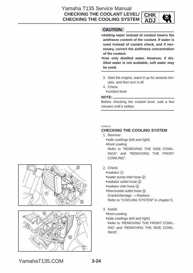
1
2
3
4
5
CHKADJ
3-24
CHECKING THE COOLANT LEVEL/CHECKING THE COOLING SYSTEM
cC99Adding water instead of coolant lowers theantifreeze content of the coolant. If water isused instead of coolant check, and if nec-essary, correct the antifreeze concentrationof the coolant.99Use only distilled water. However, if dis-tilled water is not available, soft water maybe used.
3. Start the engine, warm it up for several min-utes, and then turn it off.
4. Check:9coolant level
NOTE:Before checking the coolant level, wait a fewminutes until it settles.
EAS00104
CHECKING THE COOLING SYSTEM1. Remove:9side cowlings (left and right)9front cowlingRefer to “REMOVING THE SIDE COWL-INGS” and “REMOVING THE FRONTCOWLING”.
2. Check:9radiator 19water pump inlet hose 29radiator outlet hose 39radiator inlet hose 49thermostat outlet hose 5Cracks/damage → Replace.Refer to “COOLING SYSTEM” in chapter 5.
3. Install:9front cowling9side cowlings (left and right)Refer to “REMOVING THE FRONT COWL-ING” and “REMOVING THE SIDE COWL-INGS”.
5YP-F8197-E0_3_1 05.6.27 20:32 Page 24
Yamaha T135 Service Manual
YamahaT135.COM
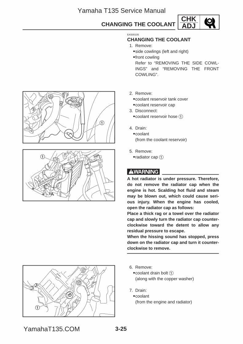
1
1
1
CHKADJ
3-25
CHANGING THE COOLANT
EAS00105
CHANGING THE COOLANT1. Remove:9side cowlings (left and right)9front cowlingRefer to “REMOVING THE SIDE COWL-INGS” and “REMOVING THE FRONTCOWLING”.
2. Remove:9coolant reservoir tank cover9coolant reservoir cap
3. Disconnect:9coolant reservoir hose 1
4. Drain:9coolant(from the coolant reservoir)
5. Remove:9radiator cap 1
wA hot radiator is under pressure. Therefore,do not remove the radiator cap when theengine is hot. Scalding hot fluid and steammay be blown out, which could cause seri-ous injury. When the engine has cooled,open the radiator cap as follows:Place a thick rag or a towel over the radiatorcap and slowly turn the radiator cap counter-clockwise toward the detent to allow anyresidual pressure to escape.When the hissing sound has stopped, pressdown on the radiator cap and turn it counter-clockwise to remove.
6. Remove:9coolant drain bolt 1(along with the copper washer)
7. Drain:9coolant(from the engine and radiator)
5YP-F8197-E0_3_1 05.6.27 20:32 Page 25
Yamaha T135 Service Manual
YamahaT135.COM
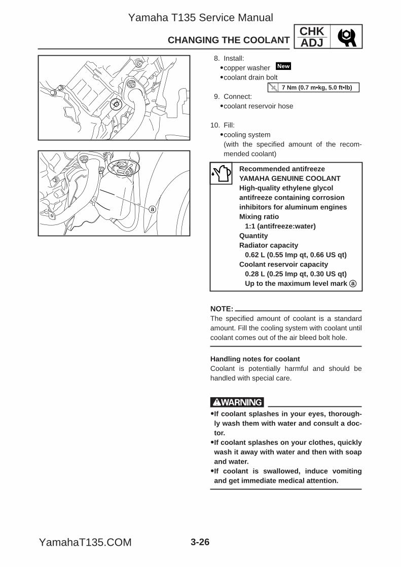
a
CHKADJ
3-26
CHANGING THE COOLANT
8. Install:9copper washer 9coolant drain bolt
9. Connect:9coolant reservoir hose
10. Fill:9cooling system(with the specified amount of the recom-mended coolant)
NOTE:The specified amount of coolant is a standardamount. Fill the cooling system with coolant untilcoolant comes out of the air bleed bolt hole.
Handling notes for coolantCoolant is potentially harmful and should behandled with special care.
w99If coolant splashes in your eyes, thorough-ly wash them with water and consult a doc-tor.99If coolant splashes on your clothes, quicklywash it away with water and then with soapand water.99If coolant is swallowed, induce vomitingand get immediate medical attention.
Recommended antifreezeYAMAHA GENUINE COOLANTHigh-quality ethylene glycolantifreeze containing corrosioninhibitors for aluminum enginesMixing ratio
1:1 (antifreeze:water)QuantityRadiator capacity
0.62 L (0.55 Imp qt, 0.66 US qt)Coolant reservoir capacity
0.28 L (0.25 Imp qt, 0.30 US qt)Up to the maximum level mark aa
7 Nm (0.7 m•kg, 5.0 ft•lb)
5YP-F8197-E0_3_1 05.6.27 20:32 Page 26
Yamaha T135 Service Manual
YamahaT135.COM
CHKADJ
3-27
cC99Adding water instead of coolant lowers theantifreeze content of the coolant. If water isused instead of coolant check, and if nec-essary, correct the antifreeze concentrationof the coolant.99Use only distilled water. However, if dis-tilled water is not available, soft water maybe used.99If coolant comes into contact with paintedsurfaces, immediately wash them withwater.99Do not mix different types of antifreeze.
11. Install:9radiator cap9coolant reservoir cap9coolant reservoir tank cover
12. Start the engine, warm it up for several min-utes, and then stop it.
13. Check:9coolant levelRefer to “CHECKING THE COOLANTLEVEL”.
NOTE:Before checking the coolant level, wait a fewminutes until the coolant has settled.
14. Install:9front cowling9side cowlings (left and right)Refer to “REMOVING THE FRONT COWL-ING” and “REMOVING THE SIDE COWL-INGS”.
CHANGING THE COOLANT
5YP-F8197-E0_3_1 05.6.27 20:32 Page 27
Yamaha T135 Service Manual
YamahaT135.COM
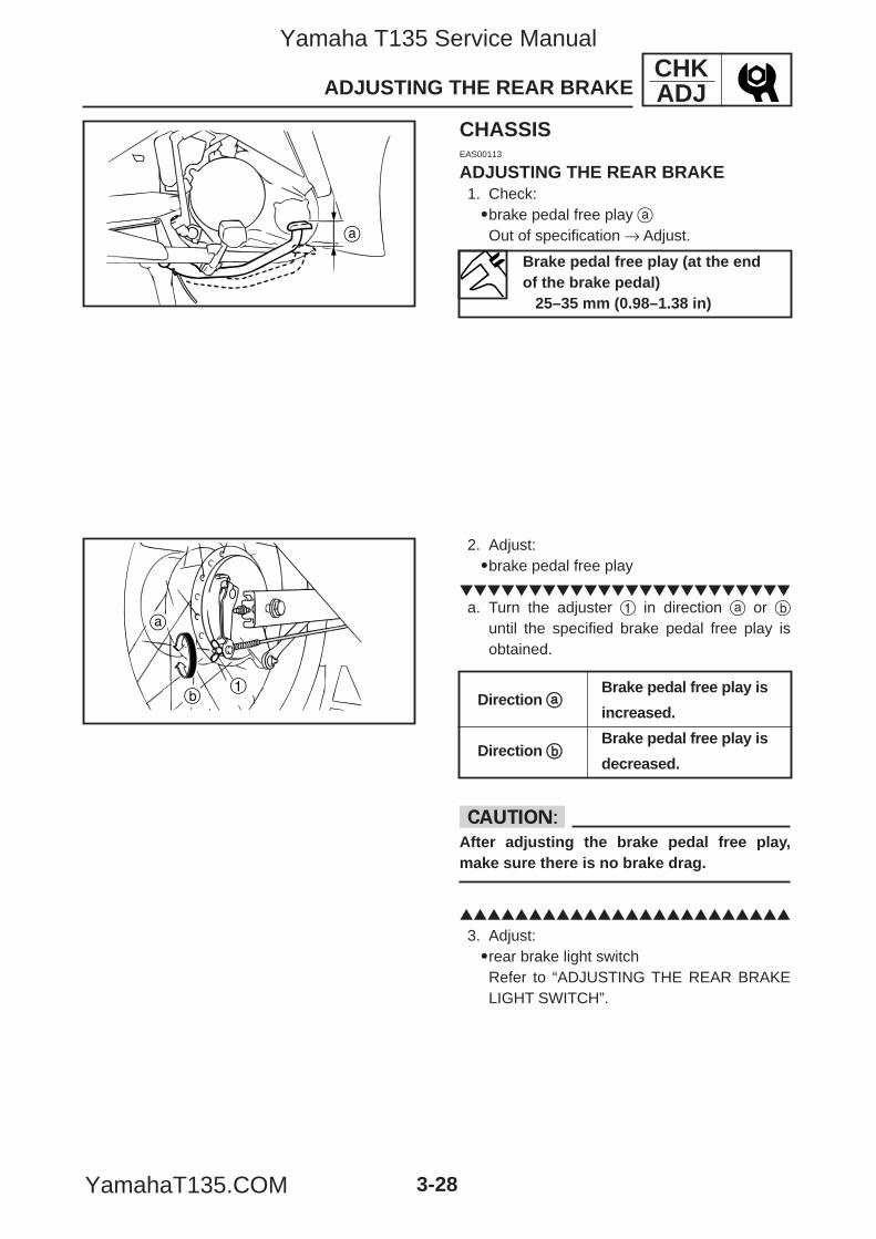
a
b
a
1
CHKADJ
3-28
ADJUSTING THE REAR BRAKE
CHASSISEAS00113
ADJUSTING THE REAR BRAKE1. Check:9brake pedal free play aOut of specification → Adjust.
Brake pedal free play (at the endof the brake pedal)
25–35 mm (0.98–1.38 in)
2. Adjust:9brake pedal free play
a. Turn the adjuster 1 in direction a or b
until the specified brake pedal free play isobtained.
cCAfter adjusting the brake pedal free play,make sure there is no brake drag.
3. Adjust:9rear brake light switchRefer to “ADJUSTING THE REAR BRAKELIGHT SWITCH”.
Direction aaBrake pedal free play is
increased.
Direction bbBrake pedal free play is
decreased.
5YP-F8197-E0_3_1 05.6.27 20:32 Page 28
Yamaha T135 Service Manual
YamahaT135.COM
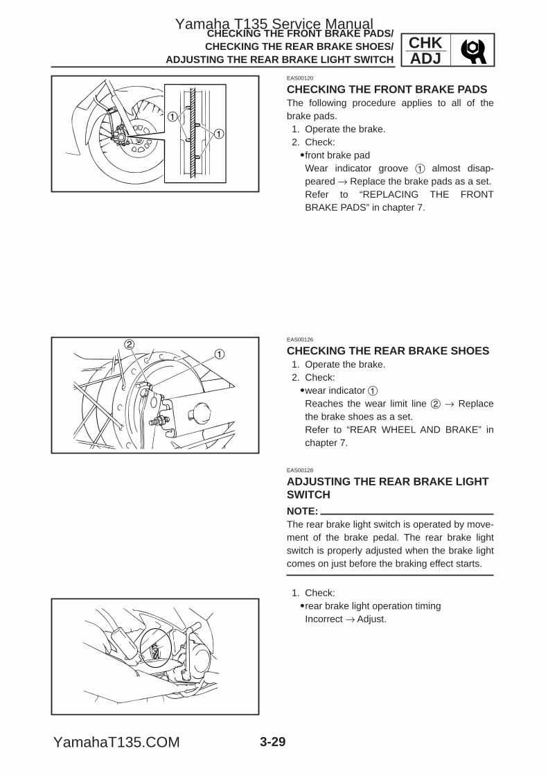
1
1
12
CHKADJ
3-29
CHECKING THE FRONT BRAKE PADS/ CHECKING THE REAR BRAKE SHOES/
ADJUSTING THE REAR BRAKE LIGHT SWITCH
EAS00120
CHECKING THE FRONT BRAKE PADSThe following procedure applies to all of thebrake pads.1. Operate the brake.2. Check:9front brake padWear indicator groove 1 almost disap-peared → Replace the brake pads as a set.Refer to “REPLACING THE FRONTBRAKE PADS” in chapter 7.
EAS00126
CHECKING THE REAR BRAKE SHOES1. Operate the brake.2. Check:9wear indicator 1Reaches the wear limit line 2 → Replacethe brake shoes as a set.Refer to “REAR WHEEL AND BRAKE” inchapter 7.
EAS00128
ADJUSTING THE REAR BRAKE LIGHTSWITCHNOTE:The rear brake light switch is operated by move-ment of the brake pedal. The rear brake lightswitch is properly adjusted when the brake lightcomes on just before the braking effect starts.
1. Check:9rear brake light operation timingIncorrect → Adjust.
5YP-F8197-E0_3_1 05.6.27 20:32 Page 29
Yamaha T135 Service Manual
YamahaT135.COM
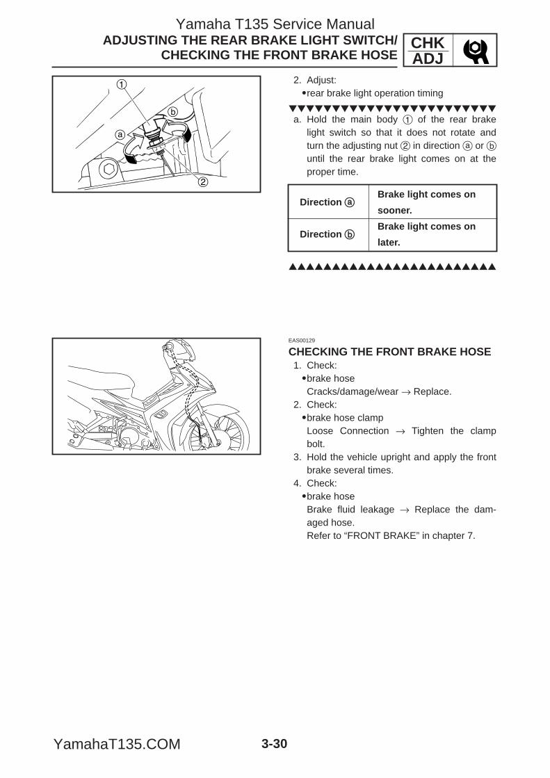
b
a
1
2
CHKADJ
3-30
ADJUSTING THE REAR BRAKE LIGHT SWITCH/CHECKING THE FRONT BRAKE HOSE
2. Adjust:9rear brake light operation timing
a. Hold the main body 1 of the rear brake
light switch so that it does not rotate andturn the adjusting nut 2 in direction a or buntil the rear brake light comes on at theproper time.
Direction aaBrake light comes on
sooner.
Direction bbBrake light comes on
later.
EAS00129
CHECKING THE FRONT BRAKE HOSE1. Check:9brake hoseCracks/damage/wear → Replace.
2. Check:9brake hose clampLoose Connection → Tighten the clampbolt.
3. Hold the vehicle upright and apply the frontbrake several times.
4. Check:9brake hoseBrake fluid leakage → Replace the dam-aged hose.Refer to “FRONT BRAKE” in chapter 7.
5YP-F8197-E0_3_1 05.6.27 20:32 Page 30
Yamaha T135 Service Manual
YamahaT135.COM
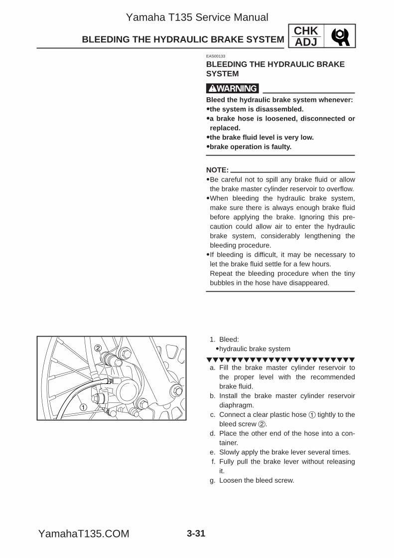
1
2
CHKADJ
3-31
BLEEDING THE HYDRAULIC BRAKE SYSTEM
EAS00133
BLEEDING THE HYDRAULIC BRAKESYSTEM
wBleed the hydraulic brake system whenever:99the system is disassembled.99a brake hose is loosened, disconnected orreplaced.99the brake fluid level is very low.99brake operation is faulty.
NOTE:9Be careful not to spill any brake fluid or allowthe brake master cylinder reservoir to overflow.9When bleeding the hydraulic brake system,make sure there is always enough brake fluidbefore applying the brake. Ignoring this pre-caution could allow air to enter the hydraulicbrake system, considerably lengthening thebleeding procedure.9If bleeding is difficult, it may be necessary tolet the brake fluid settle for a few hours.Repeat the bleeding procedure when the tinybubbles in the hose have disappeared.
1. Bleed:9hydraulic brake system
a. Fill the brake master cylinder reservoir to
the proper level with the recommendedbrake fluid.
b. Install the brake master cylinder reservoirdiaphragm.
c. Connect a clear plastic hose 1 tightly to thebleed screw 2.
d. Place the other end of the hose into a con-tainer.
e. Slowly apply the brake lever several times.f. Fully pull the brake lever without releasing
it.g. Loosen the bleed screw.
5YP-F8197-E0_3_1 05.6.27 20:32 Page 31
Yamaha T135 Service Manual
YamahaT135.COM
CHKADJ
3-32
BLEEDING THE HYDRAULIC BRAKE SYSTEM/ ADJUSTING THE DRIVE CHAIN SLACK
NOTE:Loosening the bleed screw will release the pres-sure and cause the brake lever to contact thethrottle grip.
h. Tighten the bleed screw and then releasethe brake lever.
i. Repeat steps (e) to (h) until all of the airbubbles have disappeared from the brakefluid in the plastic hose.
j. Tighten the bleed screw to specification.
k. Fill the brake master cylinder reservoir tothe proper level with the recommendedbrake fluid.Refer to “CHECKING THE BRAKE FLUIDLEVEL”.
wAfter bleeding the hydraulic brake system,check the brake operation.
Bleed screw6 Nm (0.6 m·kg, 4.3 ft·lb)
EAS00140
ADJUSTING THE DRIVE CHAIN SLACKNOTE:The drive chain slack must be checked at thetightest point on the chain.
cCA drive chain that is too tight will overloadthe engine and other vital parts, and one thatis too loose can skip and damage theswingarm or cause an accident. Therefore,keep the drive chain slack within the speci-fied limits.
5YP-F8197-E0_3_1 05.6.27 20:32 Page 32
Yamaha T135 Service Manual
YamahaT135.COM
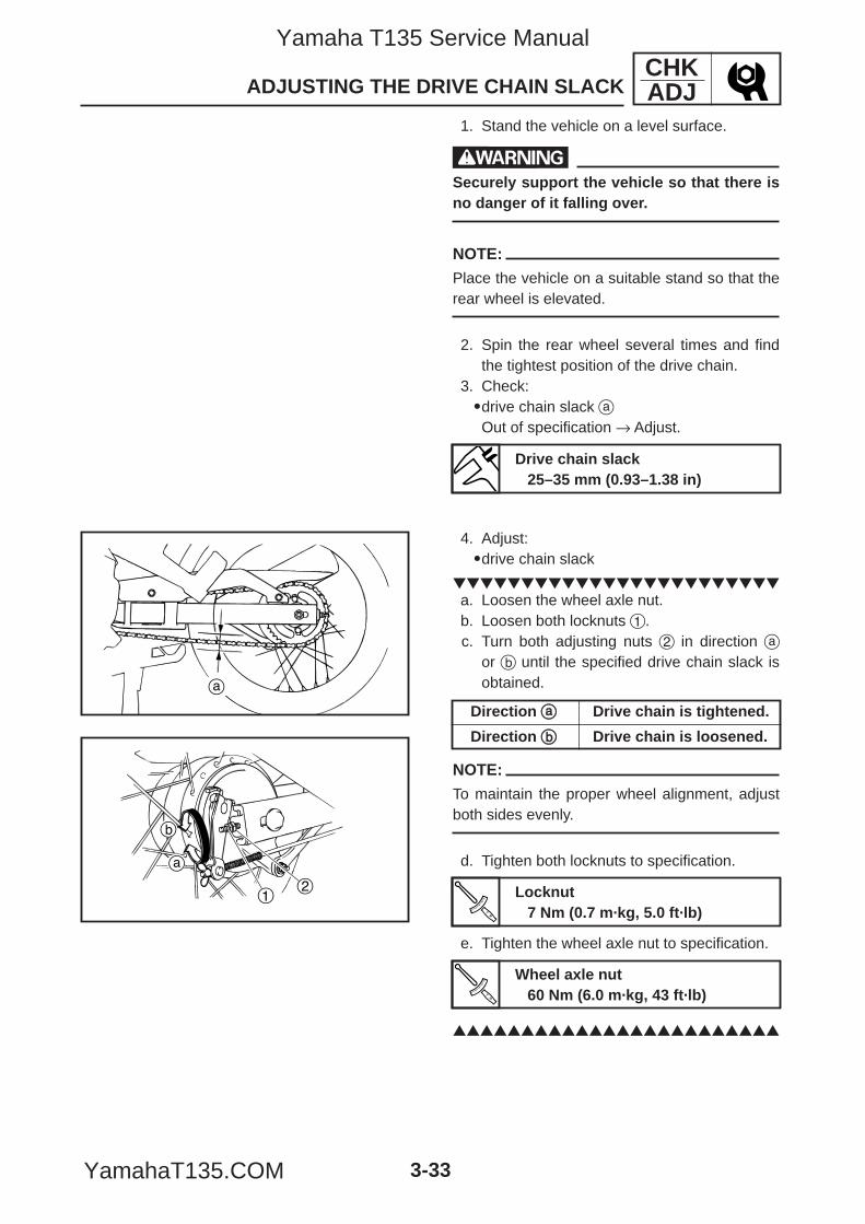
a
a
b
12
CHKADJ
3-33
ADJUSTING THE DRIVE CHAIN SLACK
1. Stand the vehicle on a level surface.
wSecurely support the vehicle so that there isno danger of it falling over.
NOTE:
Place the vehicle on a suitable stand so that therear wheel is elevated.
2. Spin the rear wheel several times and findthe tightest position of the drive chain.
3. Check:9drive chain slack aOut of specification → Adjust.
Drive chain slack25–35 mm (0.93–1.38 in)
4. Adjust:9drive chain slack
a. Loosen the wheel axle nut.b. Loosen both locknuts 1.c. Turn both adjusting nuts 2 in direction a
or b until the specified drive chain slack isobtained.
NOTE:
To maintain the proper wheel alignment, adjustboth sides evenly.
d. Tighten both locknuts to specification.
e. Tighten the wheel axle nut to specification.
Direction aa Drive chain is tightened.
Direction bb Drive chain is loosened.
Locknut7 Nm (0.7 m·kg, 5.0 ft·lb)
Wheel axle nut60 Nm (6.0 m·kg, 43 ft·lb)
5YP-F8197-E0_3_1 05.6.27 20:32 Page 33
Yamaha T135 Service Manual
YamahaT135.COM
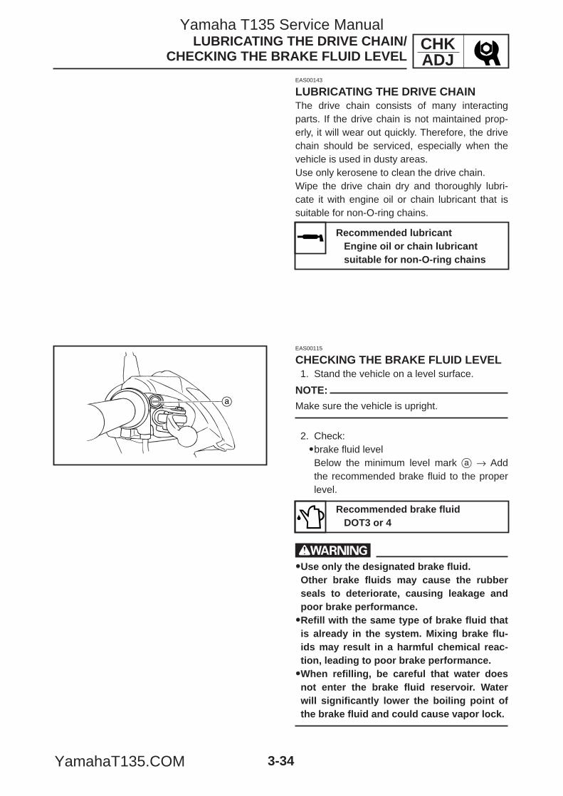
a
CHKADJ
3-34
LUBRICATING THE DRIVE CHAIN/CHECKING THE BRAKE FLUID LEVEL
EAS00143
LUBRICATING THE DRIVE CHAINThe drive chain consists of many interactingparts. If the drive chain is not maintained prop-erly, it will wear out quickly. Therefore, the drivechain should be serviced, especially when thevehicle is used in dusty areas.Use only kerosene to clean the drive chain.Wipe the drive chain dry and thoroughly lubri-cate it with engine oil or chain lubricant that issuitable for non-O-ring chains.
EAS00115
CHECKING THE BRAKE FLUID LEVEL1. Stand the vehicle on a level surface.
NOTE:
Make sure the vehicle is upright.
2. Check:9brake fluid levelBelow the minimum level mark a → Addthe recommended brake fluid to the properlevel.
w99Use only the designated brake fluid.Other brake fluids may cause the rubberseals to deteriorate, causing leakage andpoor brake performance.99Refill with the same type of brake fluid thatis already in the system. Mixing brake flu-ids may result in a harmful chemical reac-tion, leading to poor brake performance.99When refilling, be careful that water doesnot enter the brake fluid reservoir. Waterwill significantly lower the boiling point ofthe brake fluid and could cause vapor lock.
Recommended lubricantEngine oil or chain lubricant suitable for non-O-ring chains
Recommended brake fluidDOT3 or 4
5YP-F8197-E0_3_1 05.6.27 20:32 Page 34
Yamaha T135 Service Manual
YamahaT135.COM
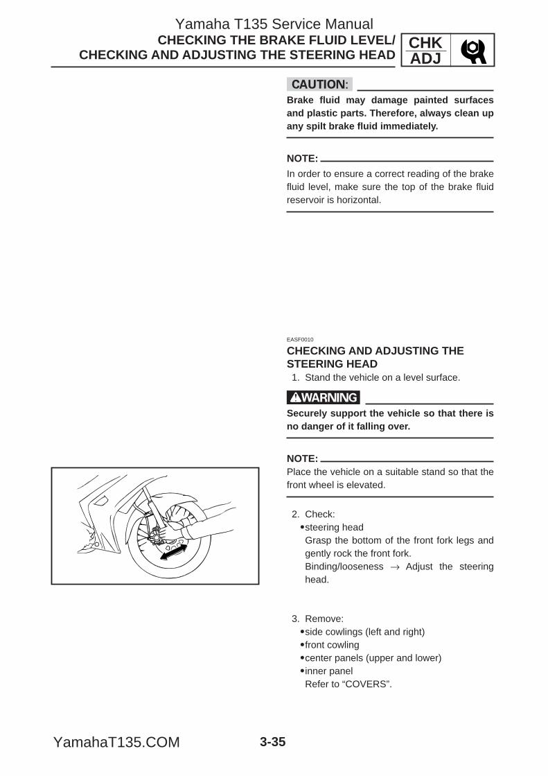
CHKADJ
3-35
CHECKING THE BRAKE FLUID LEVEL/ CHECKING AND ADJUSTING THE STEERING HEAD
cCBrake fluid may damage painted surfacesand plastic parts. Therefore, always clean upany spilt brake fluid immediately.
NOTE:
In order to ensure a correct reading of the brakefluid level, make sure the top of the brake fluidreservoir is horizontal.
EASF0010
CHECKING AND ADJUSTING THESTEERING HEAD1. Stand the vehicle on a level surface.
wSecurely support the vehicle so that there isno danger of it falling over.
NOTE:Place the vehicle on a suitable stand so that thefront wheel is elevated.
2. Check:9steering headGrasp the bottom of the front fork legs andgently rock the front fork.Binding/looseness → Adjust the steeringhead.
3. Remove:9side cowlings (left and right)9front cowling9center panels (upper and lower)9inner panelRefer to “COVERS”.
5YP-F8197-E0_3_1 05.6.27 20:32 Page 35
Yamaha T135 Service Manual
YamahaT135.COM
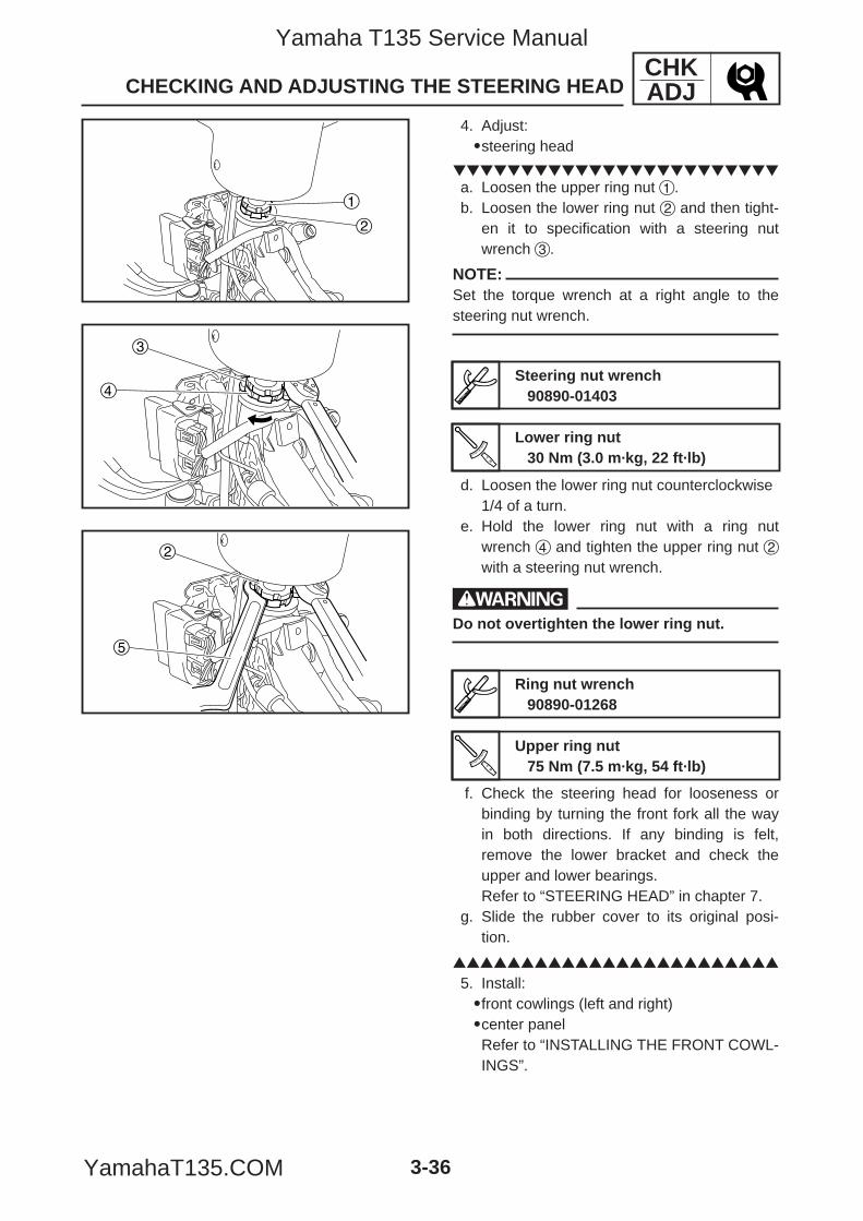
1
2
4
3
5
2
CHKADJ
3-36
CHECKING AND ADJUSTING THE STEERING HEAD
4. Adjust:9steering head
a. Loosen the upper ring nut 1.b. Loosen the lower ring nut 2 and then tight-
en it to specification with a steering nutwrench 3.
NOTE:Set the torque wrench at a right angle to thesteering nut wrench.
d. Loosen the lower ring nut counterclockwise1/4 of a turn.
e. Hold the lower ring nut with a ring nutwrench 4 and tighten the upper ring nut 2with a steering nut wrench.
wDo not overtighten the lower ring nut.
f. Check the steering head for looseness orbinding by turning the front fork all the wayin both directions. If any binding is felt,remove the lower bracket and check theupper and lower bearings.Refer to “STEERING HEAD” in chapter 7.
g. Slide the rubber cover to its original posi-tion.
5. Install:9front cowlings (left and right)9center panelRefer to “INSTALLING THE FRONT COWL-INGS”.
Steering nut wrench90890-01403
Lower ring nut30 Nm (3.0 m·kg, 22 ft·lb)
Ring nut wrench90890-01268
Upper ring nut75 Nm (7.5 m·kg, 54 ft·lb)
5YP-F8197-E0_3_1 05.6.27 20:32 Page 36
Yamaha T135 Service Manual
YamahaT135.COM
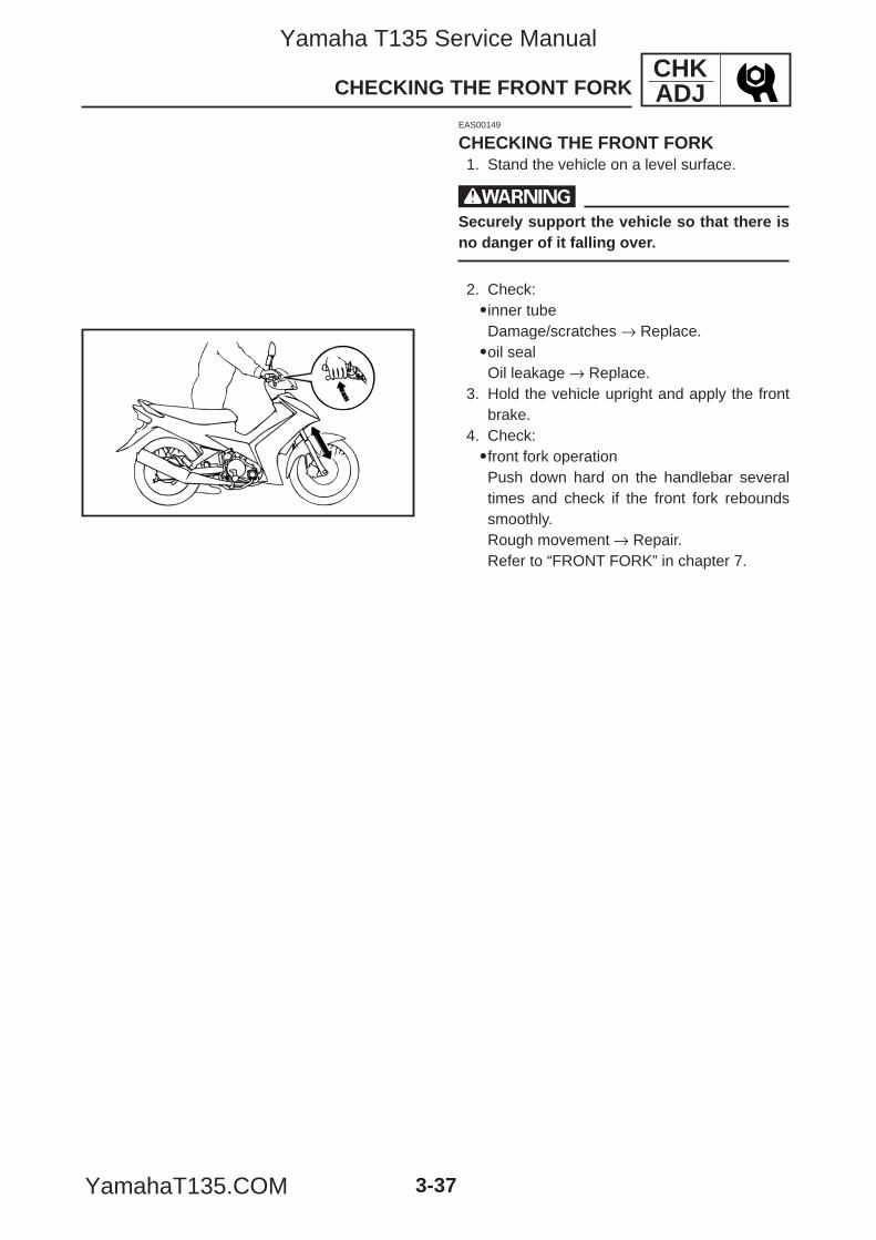
CHKADJ
3-37
CHECKING THE FRONT FORK
EAS00149
CHECKING THE FRONT FORK1. Stand the vehicle on a level surface.
wSecurely support the vehicle so that there isno danger of it falling over.
2. Check:9inner tubeDamage/scratches → Replace.9oil sealOil leakage → Replace.
3. Hold the vehicle upright and apply the frontbrake.
4. Check:9front fork operationPush down hard on the handlebar severaltimes and check if the front fork reboundssmoothly.Rough movement → Repair.Refer to “FRONT FORK” in chapter 7.
5YP-F8197-E0_3_1 05.6.27 20:32 Page 37
Yamaha T135 Service Manual
YamahaT135.COM
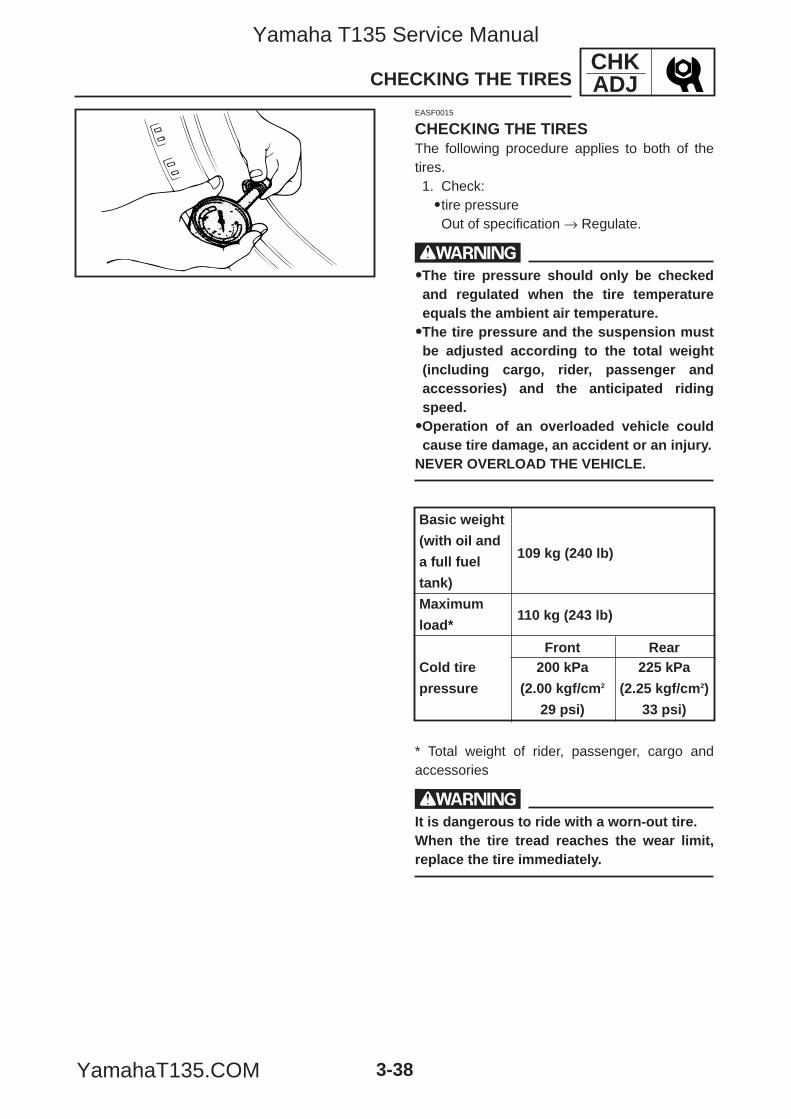
CHKADJ
3-38
CHECKING THE TIRES
EASF0015
CHECKING THE TIRESThe following procedure applies to both of thetires.1. Check:9tire pressureOut of specification → Regulate.
w99The tire pressure should only be checkedand regulated when the tire temperatureequals the ambient air temperature.99The tire pressure and the suspension mustbe adjusted according to the total weight(including cargo, rider, passenger andaccessories) and the anticipated ridingspeed.99Operation of an overloaded vehicle couldcause tire damage, an accident or an injury.
NEVER OVERLOAD THE VEHICLE.
* Total weight of rider, passenger, cargo andaccessories
wIt is dangerous to ride with a worn-out tire.When the tire tread reaches the wear limit,replace the tire immediately.
Basic weight
(with oil and109 kg (240 lb)
a full fuel
tank)
Maximum110 kg (243 lb)
load*
Front RearCold tire 200 kPa 225 kPa
pressure (2.00 kgf/cm2 (2.25 kgf/cm2)
29 psi) 33 psi)
5YP-F8197-E0_3_1 05.6.27 20:32 Page 38
Yamaha T135 Service Manual
YamahaT135.COM
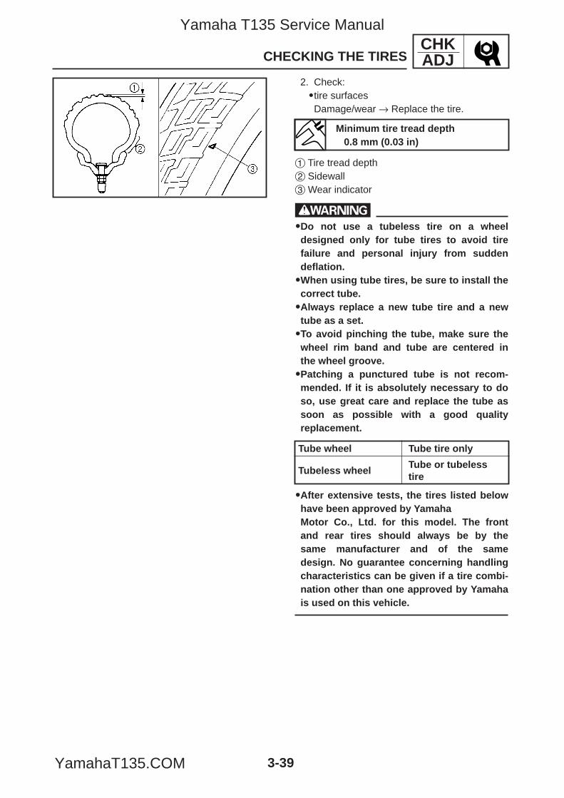
CHKADJ
3-39
CHECKING THE TIRES
2. Check:9tire surfacesDamage/wear → Replace the tire.
1 Tire tread depth2 Sidewall3 Wear indicator
w99Do not use a tubeless tire on a wheeldesigned only for tube tires to avoid tirefailure and personal injury from suddendeflation.99When using tube tires, be sure to install thecorrect tube.99Always replace a new tube tire and a newtube as a set.99To avoid pinching the tube, make sure thewheel rim band and tube are centered inthe wheel groove.99Patching a punctured tube is not recom-mended. If it is absolutely necessary to doso, use great care and replace the tube assoon as possible with a good qualityreplacement.
99After extensive tests, the tires listed belowhave been approved by YamahaMotor Co., Ltd. for this model. The frontand rear tires should always be by thesame manufacturer and of the samedesign. No guarantee concerning handlingcharacteristics can be given if a tire combi-nation other than one approved by Yamahais used on this vehicle.
Tube wheel Tube tire only
Tubeless wheelTube or tubelesstire
Minimum tire tread depth0.8 mm (0.03 in)
5YP-F8197-E0_3_1 05.6.27 20:32 Page 39
Yamaha T135 Service Manual
YamahaT135.COM
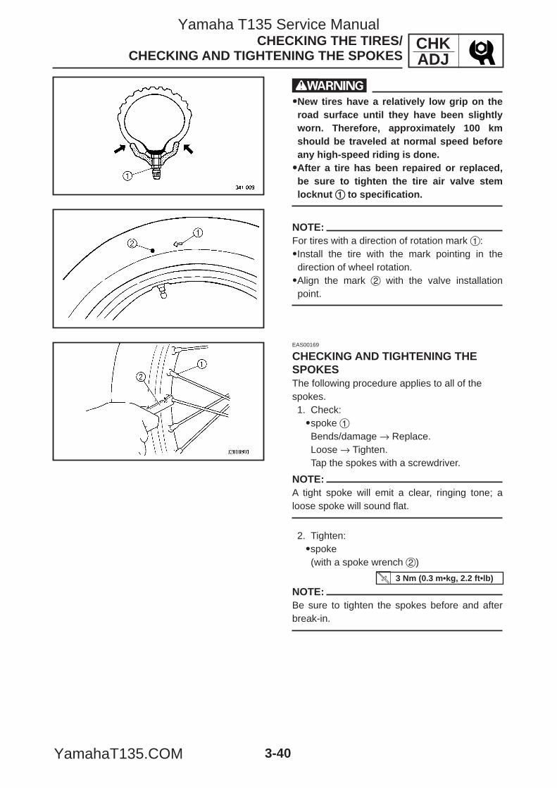
CHKADJ
3-40
EAS00169
CHECKING AND TIGHTENING THESPOKESThe following procedure applies to all of thespokes.1. Check:9spoke 1Bends/damage → Replace.Loose → Tighten.Tap the spokes with a screwdriver.
NOTE:A tight spoke will emit a clear, ringing tone; aloose spoke will sound flat.
2. Tighten:9spoke(with a spoke wrench 2)
NOTE:Be sure to tighten the spokes before and afterbreak-in.
CHECKING THE TIRES/CHECKING AND TIGHTENING THE SPOKES
w99New tires have a relatively low grip on theroad surface until they have been slightlyworn. Therefore, approximately 100 kmshould be traveled at normal speed beforeany high-speed riding is done.99After a tire has been repaired or replaced,be sure to tighten the tire air valve stemlocknut 11 to specification.
NOTE:For tires with a direction of rotation mark 1:9Install the tire with the mark pointing in thedirection of wheel rotation.9Align the mark 2 with the valve installationpoint.
3 Nm (0.3 m•kg, 2.2 ft•lb)
5YP-F8197-E0_3_1 05.6.27 20:32 Page 40
Yamaha T135 Service Manual
YamahaT135.COM
CHKADJ
3-41
CHECKING AND LUBRICATING THE CABLES/LUBRICATING THE LEVER AND PEDALS/
LUBRICATING THE SIDESTAND/LUBRICATING THE CENTERSTAND
EAS00170
CHECKING AND LUBRICATING THECABLESThe following procedure applies to all of theinner and outer cables.
wDamaged outer cable may cause the cable tocorrode and interfere with its movement.Replace damaged outer cable and innercables as soon as possible.
1. Check:9outer cableDamage → Replace.
2. Check:9cable operationRough movement → Lubricate.
NOTE:Hold the cable end upright and pour a few dropsof lubricant into the cable sheath or use a suit-able lubricating device.
EAS00171
LUBRICATING THE LEVER AND PEDALSLubricate the pivoting point and metal-to-metalmoving parts of the lever and pedals.
EAS00172
LUBRICATING THE SIDESTANDLubricate the pivoting point and metal-to-metalmoving parts of the sidestand.
EAS00173
LUBRICATING THE CENTERSTANDLubricate the pivoting point and metal-to-metalmoving parts of the centerstand.
Recommended lubricantEngine oil or a suitable cablelubricant
Recommended lubricantLithium-soap-based grease
Recommended lubricantLithium-soap-based grease
Recommended lubricantLithium-soap-based grease
5YP-F8197-E0_3_1 05.6.27 20:32 Page 41
Yamaha T135 Service Manual
YamahaT135.COM
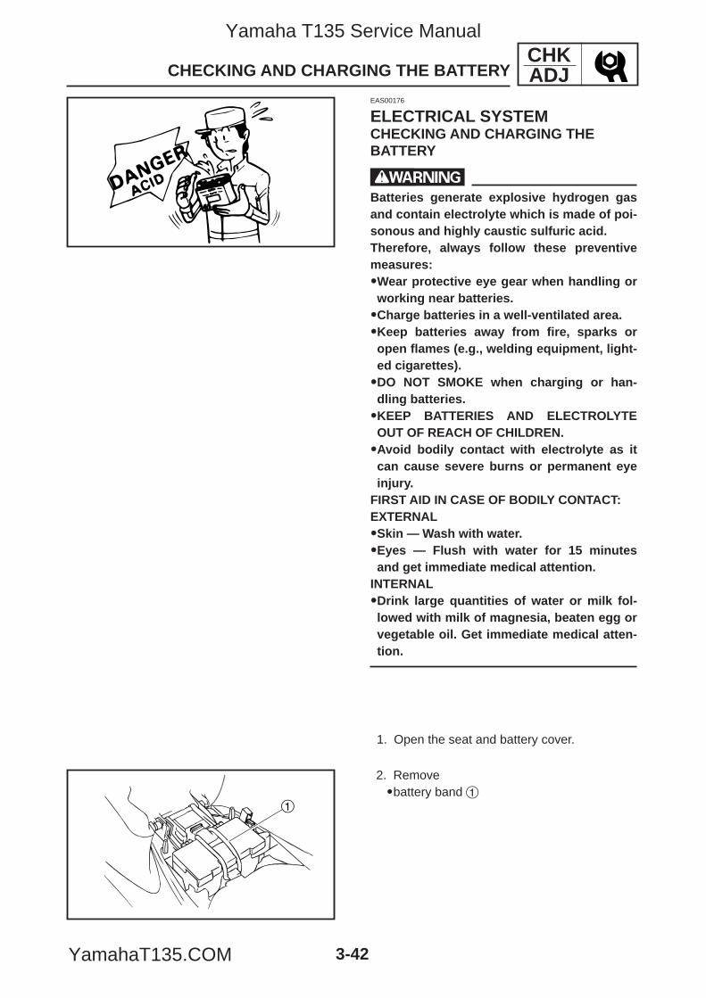
1
CHKADJ
3-42
CHECKING AND CHARGING THE BATTERY
EAS00176
ELECTRICAL SYSTEMCHECKING AND CHARGING THE BATTERY
wBatteries generate explosive hydrogen gasand contain electrolyte which is made of poi-sonous and highly caustic sulfuric acid.Therefore, always follow these preventivemeasures:99Wear protective eye gear when handling orworking near batteries.99Charge batteries in a well-ventilated area.99Keep batteries away from fire, sparks oropen flames (e.g., welding equipment, light-ed cigarettes).99DO NOT SMOKE when charging or han-dling batteries.99KEEP BATTERIES AND ELECTROLYTEOUT OF REACH OF CHILDREN.99Avoid bodily contact with electrolyte as itcan cause severe burns or permanent eyeinjury.
FIRST AID IN CASE OF BODILY CONTACT:EXTERNAL99Skin — Wash with water.99Eyes — Flush with water for 15 minutesand get immediate medical attention.
INTERNAL99Drink large quantities of water or milk fol-lowed with milk of magnesia, beaten egg orvegetable oil. Get immediate medical atten-tion.
1. Open the seat and battery cover.
2. Remove9battery band 1
5YP-F8197-E0_3_1 05.6.27 20:32 Page 42
Yamaha T135 Service Manual
YamahaT135.COM
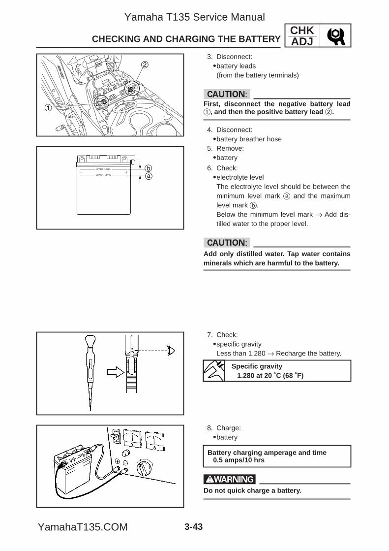
2
1
ab
CHKADJ
3-43
3. Disconnect:9battery leads(from the battery terminals)
cCFirst, disconnect the negative battery lead1, and then the positive battery lead 2.
4. Disconnect:9battery breather hose
5. Remove:9battery
CHECKING AND CHARGING THE BATTERY
6. Check:9electrolyte levelThe electrolyte level should be between theminimum level mark a and the maximumlevel mark b.Below the minimum level mark → Add dis-tilled water to the proper level.
cCAdd only distilled water. Tap water containsminerals which are harmful to the battery.
7. Check:9specific gravityLess than 1.280 → Recharge the battery.
8. Charge:9battery
wDo not quick charge a battery.
Battery charging amperage and time0.5 amps/10 hrs
Specific gravity1.280 at 20 ˚C (68 ˚F)
5YP-F8197-E0_3_1 05.6.27 20:32 Page 43
Yamaha T135 Service Manual
YamahaT135.COM
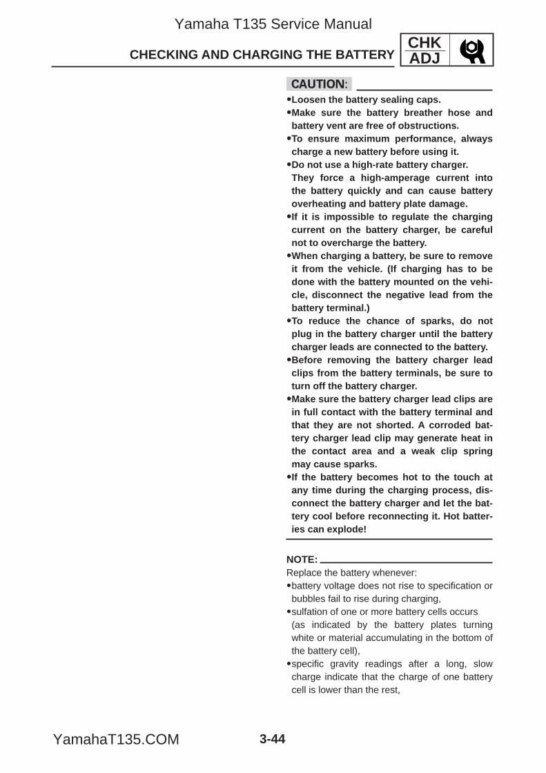
CHKADJ
3-44
cC99Loosen the battery sealing caps.99Make sure the battery breather hose andbattery vent are free of obstructions.99To ensure maximum performance, alwayscharge a new battery before using it.99Do not use a high-rate battery charger.They force a high-amperage current intothe battery quickly and can cause batteryoverheating and battery plate damage.99If it is impossible to regulate the chargingcurrent on the battery charger, be carefulnot to overcharge the battery.99When charging a battery, be sure to removeit from the vehicle. (If charging has to bedone with the battery mounted on the vehi-cle, disconnect the negative lead from thebattery terminal.)99To reduce the chance of sparks, do notplug in the battery charger until the batterycharger leads are connected to the battery.99Before removing the battery charger leadclips from the battery terminals, be sure toturn off the battery charger.99Make sure the battery charger lead clips arein full contact with the battery terminal andthat they are not shorted. A corroded bat-tery charger lead clip may generate heat inthe contact area and a weak clip springmay cause sparks.99If the battery becomes hot to the touch atany time during the charging process, dis-connect the battery charger and let the bat-tery cool before reconnecting it. Hot batter-ies can explode!
NOTE:Replace the battery whenever:9battery voltage does not rise to specification orbubbles fail to rise during charging,9sulfation of one or more battery cells occurs(as indicated by the battery plates turningwhite or material accumulating in the bottom ofthe battery cell),9specific gravity readings after a long, slowcharge indicate that the charge of one batterycell is lower than the rest,
CHECKING AND CHARGING THE BATTERY
5YP-F8197-E0_3_1 05.6.27 20:32 Page 44
Yamaha T135 Service Manual
YamahaT135.COM
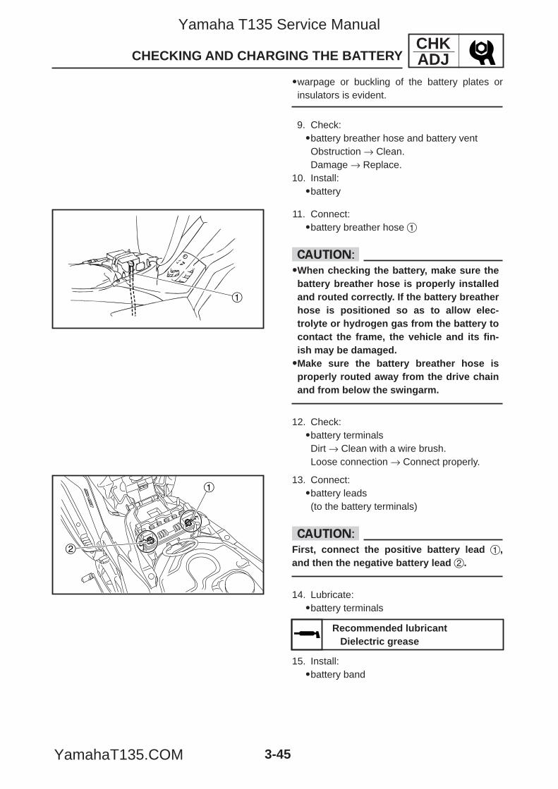
1
1
2
CHKADJ
3-45
9warpage or buckling of the battery plates orinsulators is evident.
9. Check:9battery breather hose and battery ventObstruction → Clean.Damage → Replace.
10. Install:9battery
CHECKING AND CHARGING THE BATTERY
13. Connect:9battery leads(to the battery terminals)
cCFirst, connect the positive battery lead 1,and then the negative battery lead 2.
14. Lubricate:9battery terminals
15. Install:9battery band
Recommended lubricantDielectric grease
11. Connect:9battery breather hose 1
cC99When checking the battery, make sure thebattery breather hose is properly installedand routed correctly. If the battery breatherhose is positioned so as to allow elec-trolyte or hydrogen gas from the battery tocontact the frame, the vehicle and its fin-ish may be damaged.99Make sure the battery breather hose isproperly routed away from the drive chainand from below the swingarm.
12. Check:9battery terminalsDirt → Clean with a wire brush.Loose connection → Connect properly.
5YP-F8197-E0_3_1 05.6.27 20:33 Page 45
Yamaha T135 Service Manual
YamahaT135.COM
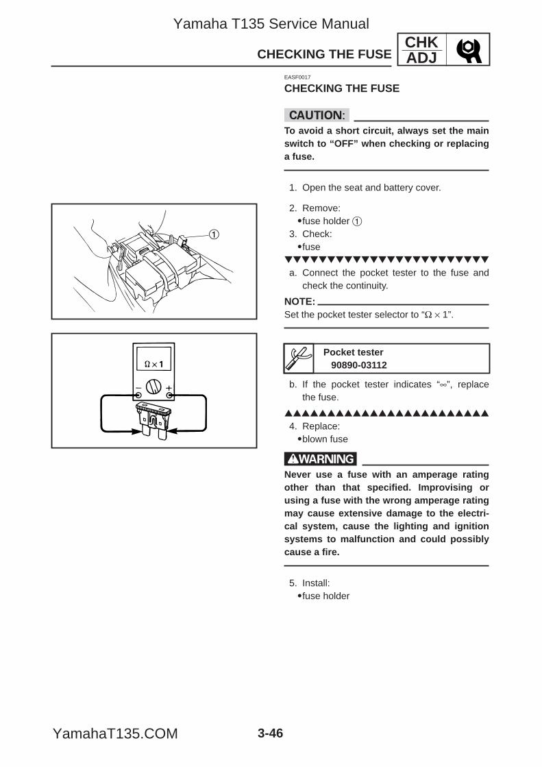
1
CHKADJ
3-46
EASF0017
CHECKING THE FUSE
cCTo avoid a short circuit, always set the mainswitch to “OFF” when checking or replacinga fuse.
1. Open the seat and battery cover.
CHECKING THE FUSE
2. Remove:9fuse holder 1
3. Check:9fuse
a. Connect the pocket tester to the fuse andcheck the continuity.
NOTE:Set the pocket tester selector to “Ω × 1”.
b. If the pocket tester indicates “∞”, replacethe fuse.
4. Replace:9blown fuse
wNever use a fuse with an amperage ratingother than that specified. Improvising orusing a fuse with the wrong amperage ratingmay cause extensive damage to the electri-cal system, cause the lighting and ignitionsystems to malfunction and could possiblycause a fire.
5. Install:9fuse holder
Pocket tester90890-03112
5YP-F8197-E0_3_1 05.6.27 20:33 Page 46
Yamaha T135 Service Manual
YamahaT135.COM
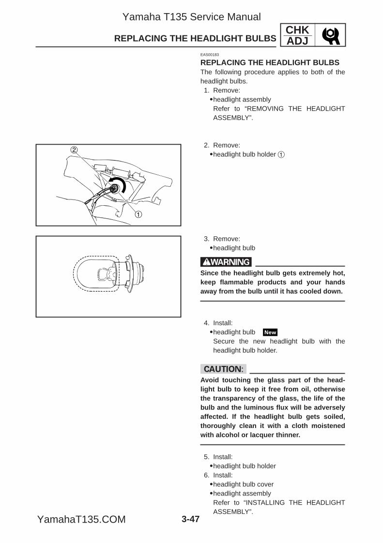
1
2
CHKADJ
3-47
EAS00183
REPLACING THE HEADLIGHT BULBSThe following procedure applies to both of theheadlight bulbs.1. Remove:9headlight assemblyRefer to “REMOVING THE HEADLIGHTASSEMBLY”.
2. Remove:9headlight bulb holder 1
REPLACING THE HEADLIGHT BULBS
3. Remove:9headlight bulb
wSince the headlight bulb gets extremely hot,keep flammable products and your handsaway from the bulb until it has cooled down.
4. Install:9headlight bulbSecure the new headlight bulb with theheadlight bulb holder.
cCAvoid touching the glass part of the head-light bulb to keep it free from oil, otherwisethe transparency of the glass, the life of thebulb and the luminous flux will be adverselyaffected. If the headlight bulb gets soiled,thoroughly clean it with a cloth moistenedwith alcohol or lacquer thinner.
5. Install:9headlight bulb holder
6. Install:9headlight bulb cover9headlight assemblyRefer to “INSTALLING THE HEADLIGHTASSEMBLY”.
5YP-F8197-E0_3_1 05.6.27 20:33 Page 47
Yamaha T135 Service Manual
YamahaT135.COM
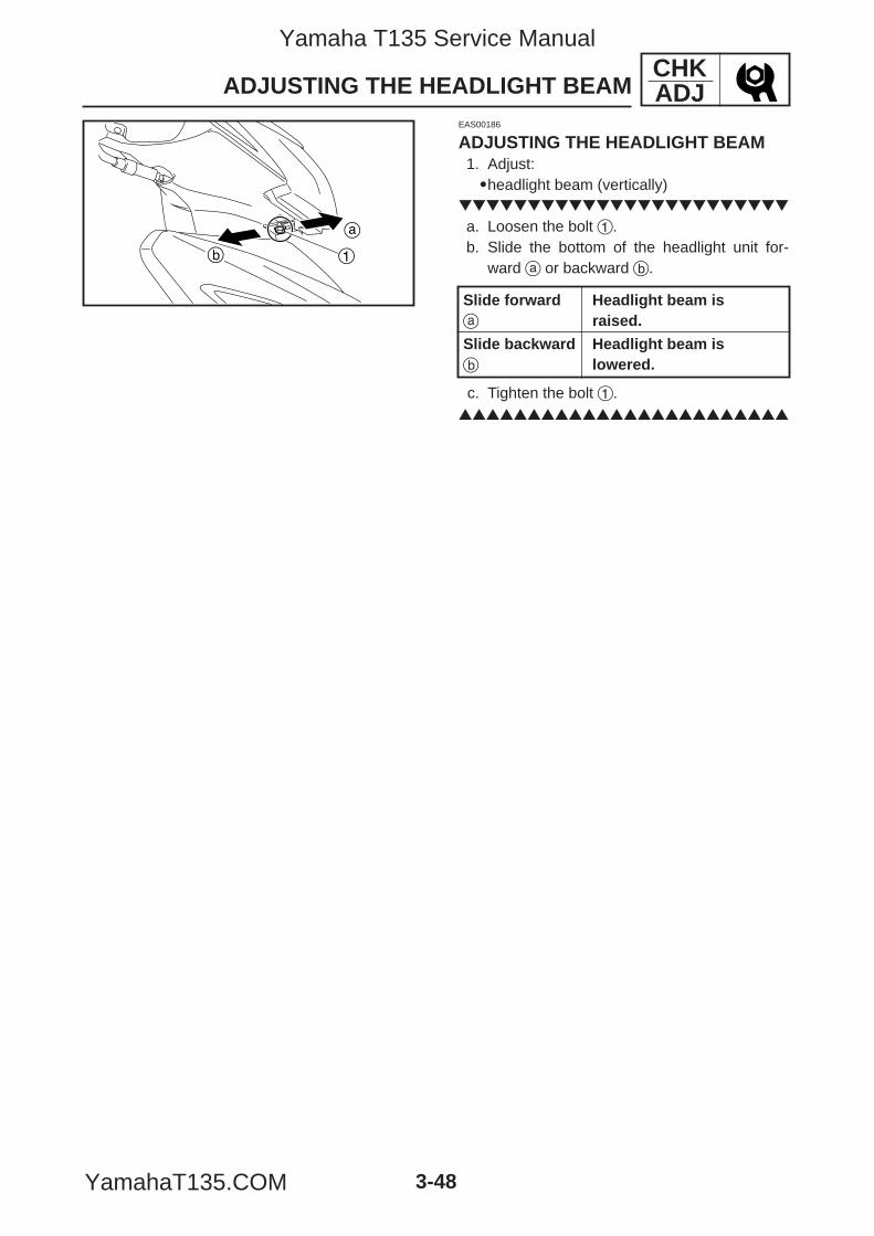
a
b 1
CHKADJ
3-48
EAS00186
ADJUSTING THE HEADLIGHT BEAM1. Adjust:9headlight beam (vertically)
a. Loosen the bolt 1.b. Slide the bottom of the headlight unit for-
ward a or backward b.
c. Tighten the bolt 1.
ADJUSTING THE HEADLIGHT BEAM
Slide forward Headlight beam isa raised.
Slide backward Headlight beam isb lowered.
5YP-F8197-E0_3_1 05.6.27 20:33 Page 48
Yamaha T135 Service Manual
YamahaT135.COM
ENG
CHAPTER 4ENGINE
REMOVING THE ENGINE ..................................................................................... 4-1COOLING SYSTEM .......................................................................................... 4-1ENGINE OIL ...................................................................................................... 4-1CARBURETOR ................................................................................................. 4-1FOOTREST ...................................................................................................... 4-2MUFFLER ......................................................................................................... 4-2BRAKE PEDAL ................................................................................................. 4-2SHIFT PEDAL ................................................................................................... 4-2SIDE COWLING BRACKET ............................................................................. 4-3WIRE, CABLE AND HOSE ............................................................................... 4-3ENGINE ASSEMBLY ........................................................................................ 4-4
INSTALLING THE ENGINE ................................................................................... 4-5ENGINE ASSEMBLY ........................................................................................ 4-5WIRE, CABLE AND HOSE ............................................................................... 4-6SIDE COWLING BRACKET ............................................................................. 4-6SHIFT PEDAL ................................................................................................... 4-6BRAKE PEDAL ................................................................................................. 4-6MUFFLER ......................................................................................................... 4-6FOOTREST ...................................................................................................... 4-7CARBURETOR ................................................................................................. 4-7COOLING SYSTEM .......................................................................................... 4-7ENGINE OIL ...................................................................................................... 4-7
CYLINDER HEAD .................................................................................................. 4-8REMOVING THE CYLINDER HEAD ................................................................ 4-9CHECKING THE CYLINDER HEAD ................................................................. 4-11CHECKING TIMING CHAIN GUIDE ................................................................. 4-12CHECKING THE TIMING CHAIN TENSIONER ............................................... 4-13INSTALLING THE CYLINDER HEAD ............................................................... 4-13
CAMSHAFT ............................................................................................................ 4-17REMOVING THE ROCKER ARMS AND CAMSHAFT ...................................... 4-18CHECKING THE CAMSHAFT .......................................................................... 4-19CHECKING THE ROCKER ARMS AND ROCKER ARM SHAFTS .................. 4-19CHECKING THE CAMSHAFT SPROCKET ..................................................... 4-21INSTALLING THE CAMSHAFT AND ROCKER ARMS .................................... 4-21
VALVES AND VALVE SPRINGS ............................................................................ 4-22REMOVING THE VALVES ................................................................................ 4-23CHECKING THE VALVES AND VALVE GUIDES ............................................. 4-24CHECKING THE VALVE SEATS ...................................................................... 4-26CHECKING THE VALVE SPRINGS .................................................................. 4-28INSTALLING THE VALVES ............................................................................... 4-29
5YP-F8197-E0_4_1 05.6.30 16:45 Page 1
Yamaha T135 Service Manual
YamahaT135.COM
ENG
CYLINDER AND PISTON ...................................................................................... 4-31REMOVING THE CYLINDER AND PISTON .................................................... 4-32CHECKING THE CYLINDER AND PISTON ..................................................... 4-33CHECKING THE PISTON RINGS .................................................................... 4-34CHECKING THE PISTON PIN .......................................................................... 4-35INSTALLING THE PISTON AND CYLINDER ................................................... 4-36
GENERATOR AND STARTER CLUTCH ............................................................... 4-38REMOVING THE GENERATOR ....................................................................... 4-39REMOVING THE STARTER CLUTCH (T135SE) ............................................. 4-40CHECKING THE STARTER CLUTCH (T135SE) ............................................. 4-41INSTALLING THE STARTER CLUTCH (T135SE) ............................................ 4-42INSTALLING THE GENERATOR ...................................................................... 4-42
OIL PUMP .............................................................................................................. 4-44REMOVING THE OIL PUMP ............................................................................ 4-45DISASSEMBLING THE OIL PUMP .................................................................. 4-45CHECKING THE OIL PUMP ............................................................................. 4-46ASSEMBLING THE OIL PUMP ........................................................................ 4-47INSTALLING THE OIL PUMP ........................................................................... 4-48
CLUTCH ................................................................................................................. 4-49REMOVING THE CLUTCH ............................................................................... 4-50CHECKING THE FRICTION PLATES .............................................................. 4-52CHECKING THE CLUTCH PLATES ................................................................. 4-52CHECKING THE CLUTCH SPRINGS .............................................................. 4-53CHECKING THE CLUTCH HOUSING ............................................................. 4-53CHECKING THE CLUTCH BOSS .................................................................... 4-53CHECKING THE CLUTCH PRESSURE PLATE .............................................. 4-54CHECKING THE CLUTCH PUSH RODS ......................................................... 4-54CHECKING THE PRIMARY DRIVEN GEAR .................................................... 4-54CHECKING THE CLUTCH SHOE HOUSING .................................................. 4-55CHECKING THE CLUTCH SHOE .................................................................... 4-55CHECKING THE CAGE .................................................................................... 4-55CHECKING THE CLUTCH RELEASE SHIFT ARM .......................................... 4-56INSTALLING THE CLUTCH .............................................................................. 4-56
SHIFT SHAFT ........................................................................................................ 4-58REMOVING THE SHIFT SHAFT ...................................................................... 4-59CHECKING THE SHIFT SHAFT ....................................................................... 4-61CHECKING THE STOPPER LEVER ................................................................ 4-61CHECKING THE SHIFT GUIDE ....................................................................... 4-61CHECKING THE OIL SEAL .............................................................................. 4-61INSTALLING THE SHIFT SHAFT ..................................................................... 4-62
CRANKCASE AND CRANKSHAFT ...................................................................... 4-63DISASSEMBLING THE CRANKCASE ............................................................. 4-64CHECKING THE CRANKSHAFT AND CONNECTING ROD ........................... 4-65CHECKING THE CRANKCASE ....................................................................... 4-67
5YP-F8197-E0_4_1 05.6.27 19:32 Page 2
Yamaha T135 Service Manual
YamahaT135.COM
ENG
CHECKING THE BEARINGS ........................................................................... 4-67CHECKING THE TIMING CHAIN GUIDE ......................................................... 4-67CHECKING THE TIMING CHAIN ..................................................................... 4-67INSTALLING THE CRANKSHAFT .................................................................... 4-68ASSEMBLING THE CRANKCASE ................................................................... 4-68
KICKSTARTER ...................................................................................................... 4-70REMOVING THE KICKSTARTER .................................................................... 4-71CHECKING THE KICKSTARTER ..................................................................... 4-73INSTALLING THE KICKSTARTER ................................................................... 4-74
TRANSMISSION .................................................................................................... 4-76REMOVING THE TRANSMISSION .................................................................. 4-77DISASSEMBLING THE TRANSMISSION ........................................................ 4-77CHECKING THE SHIFT FORKS ...................................................................... 4-78CHECKING THE SHIFT DRUM ASSEMBLY .................................................... 4-79CHECKING THE TRANSMISSION ................................................................... 4-79INSTALLING THE TRANSMISSION ................................................................. 4-80
5YP-F8197-E0_4_1 05.6.27 19:32 Page 3
Yamaha T135 Service Manual
YamahaT135.COM

ENG
5YP-F8197-E0_4_1 05.6.27 19:32 Page 4
Yamaha T135 Service Manual
YamahaT135.COM
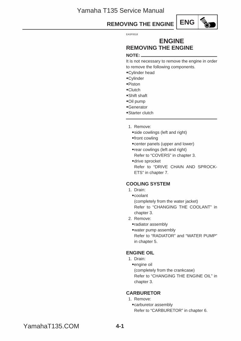
4-1
ENGREMOVING THE ENGINE
EASF0018
ENGINEREMOVING THE ENGINENOTE:It is not necessary to remove the engine in orderto remove the following components.9Cylinder head9Cylinder9Piston9Clutch9Shift shaft9Oil pump9Generator9Starter clutch
1. Remove:9side cowlings (left and right)9front cowling9center panels (upper and lower)9rear cowlings (left and right)Refer to “COVERS” in chapter 3.9drive sprocketRefer to “DRIVE CHAIN AND SPROCK-ETS” in chapter 7.
COOLING SYSTEM1. Drain:9coolant(completely from the water jacket)Refer to “CHANGING THE COOLANT” inchapter 3.
2. Remove:9radiator assembly9water pump assemblyRefer to “RADIATOR” and “WATER PUMP”in chapter 5.
ENGINE OIL1. Drain:9engine oil(completely from the crankcase)Refer to “CHANGING THE ENGINE OIL” inchapter 3.
CARBURETOR1. Remove:9carburetor assemblyRefer to “CARBURETOR” in chapter 6.
5YP-F8197-E0_4_1 05.6.27 19:32 Page 1
Yamaha T135 Service Manual
YamahaT135.COM
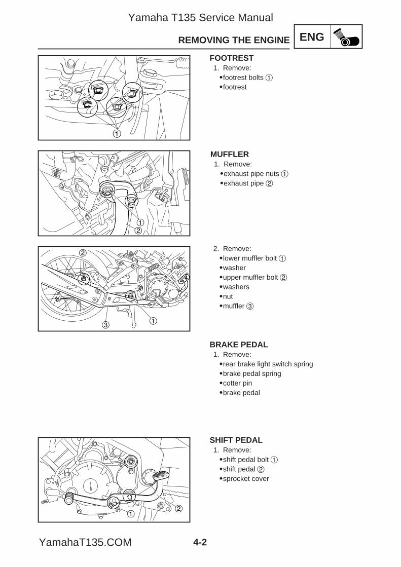
4-2
ENGREMOVING THE ENGINE
12
21
MUFFLER1. Remove:9exhaust pipe nuts 19exhaust pipe 2
2. Remove:9lower muffler bolt 19washer9upper muffler bolt 29washers9nut9muffler 3
BRAKE PEDAL1. Remove:9rear brake light switch spring9brake pedal spring9cotter pin9brake pedal
SHIFT PEDAL1. Remove:9shift pedal bolt 19shift pedal 29sprocket cover
1
FOOTREST1. Remove:9footrest bolts 19footrest
1
2
3
5YP-F8197-E0_4_1 05.6.27 19:32 Page 2
Yamaha T135 Service Manual
YamahaT135.COM
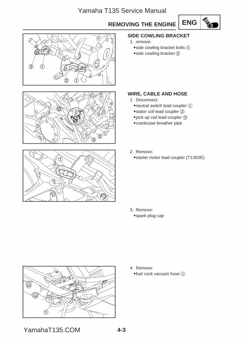
ENGREMOVING THE ENGINE
12
12
21
3
1
SIDE COWLING BRACKET1. remove:9side cowling bracket bolts 19side cowling bracket 2
WIRE, CABLE AND HOSE1. Disconnect:9neutral switch lead coupler 19stator coil lead coupler 29pick up coil lead coupler 39crankcase breather pipe
2. Remove:9starter motor lead coupler (T135SE)
3. Remove:9spark plug cap
4-3
4. Remove:9fuel cock vacuum hose 1
1
5YP-F8197-E0_4_1 05.6.27 19:32 Page 3
Yamaha T135 Service Manual
YamahaT135.COM
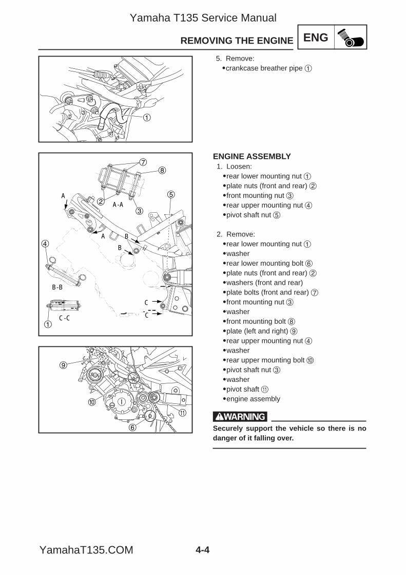
4-4
ENGREMOVING THE ENGINE
6
0
q
9
ENGINE ASSEMBLY1. Loosen:9rear lower mounting nut 19plate nuts (front and rear) 29front mounting nut 39rear upper mounting nut 49pivot shaft nut 5
2. Remove:9rear lower mounting nut 19washer9rear lower mounting bolt 69plate nuts (front and rear) 29washers (front and rear)9plate bolts (front and rear) 79front mounting nut 39washer9front mounting bolt 89plate (left and right) 99rear upper mounting nut 49washer9rear upper mounting bolt 09pivot shaft nut 39washer9pivot shaft q9engine assembly
wSecurely support the vehicle so there is nodanger of it falling over.
1
5. Remove:9crankcase breather pipe 1
A
A B
B
C
CC-C
A-A
B-B
5
1
4
3
2
78
5YP-F8197-E0_4_1 05.6.27 19:32 Page 4
Yamaha T135 Service Manual
YamahaT135.COM
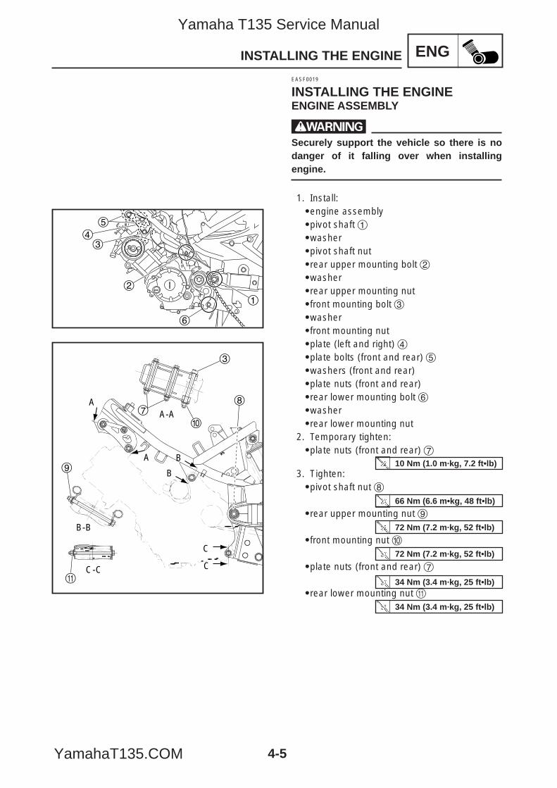
4-5
ENGINSTALLING THE ENGINE
EASF0019
INSTALLING THE ENGINEENGINE ASSEMBLY
wSecurely support the vehicle so there is nodanger of it falling over when installingengine.
1. Install:9engine assembly9pivot shaft 19washer9pivot shaft nut9rear upper mounting bolt 29washer9rear upper mounting nut9front mounting bolt 39washer9front mounting nut9plate (left and right) 49plate bolts (front and rear) 59washers (front and rear)9plate nuts (front and rear)9rear lower mounting bolt 69washer9rear lower mounting nut
2. Temporary tighten:9plate nuts (front and rear) 7
3. Tighten:9pivot shaft nut 8
9rear upper mounting nut 9
9front mounting nut 0
9plate nuts (front and rear) 7
9rear lower mounting nut q34 Nm (3.4 m·kg, 25 ft•lb)
34 Nm (3.4 m·kg, 25 ft•lb)
72 Nm (7.2 m·kg, 52 ft•lb)
72 Nm (7.2 m·kg, 52 ft•lb)
66 Nm (6.6 m•kg, 48 ft•lb)
10 Nm (1.0 m·kg, 7.2 ft•lb)
6
3
2
1
4
5
A
A B
B
C
CC-C
A-A
B-B
8
q
9
0
7
3
5YP-F8197-E0_4_1 05.6.27 19:32 Page 5
Yamaha T135 Service Manual
YamahaT135.COM
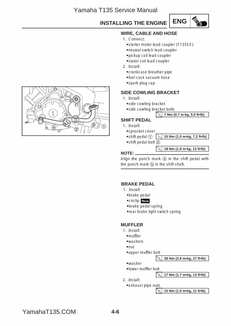
MUFFLER1. Install:9muffler9washers9nut9upper muffler bolt
9washer9lower muffler bolt
2. Install:9exhaust pipe nuts
4-6
ENGINSTALLING THE ENGINE
BRAKE PEDAL1. Install:9brake pedal9circlip 9brake pedal spring9rear brake light switch spring
WIRE, CABLE AND HOSE1. Connect:9starter motor lead coupler (T135SE)9neutral switch lead coupler9pickup coil lead coupler9stator coil lead coupler
2. Install:9crankcase breather pipe9fuel cock vacuum hose9spark plug cap
SIDE COWLING BRACKET1. Install:9side cowling bracket9side cowling bracket bolts
SHIFT PEDAL1. Install:9sprocket cover9shift pedal 19shift pedal bolt 2
NOTE:Align the punch mark a in the shift pedal withthe punch mark b in the shift shaft.
12a
b 7 Nm (0.7 m·kg, 5.0 ft•lb)
10 Nm (1.0 m•kg, 7.2 ft•lb)
18 Nm (1.8 m·kg, 13 ft•lb)
15 Nm (1.5 m•kg, 11 ft•lb)
38 Nm (3.8 m•kg, 27 ft•lb)
17 Nm (1.7 m•kg, 13 ft•lb)
5YP-F8197-E0_4_1 05.6.27 19:32 Page 6
Yamaha T135 Service Manual
YamahaT135.COM
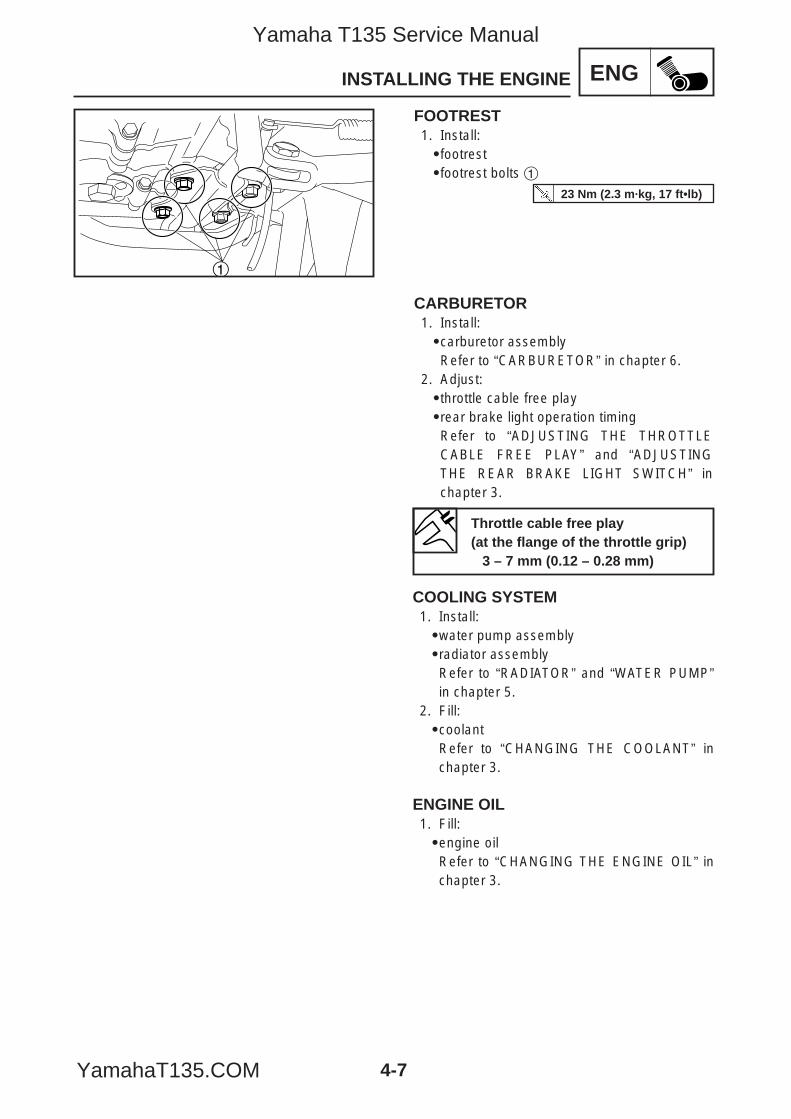
4-7
ENGINSTALLING THE ENGINE
1
CARBURETOR1. Install:9carburetor assemblyRefer to “CARBURETOR” in chapter 6.
2. Adjust:9throttle cable free play9rear brake light operation timingRefer to “ADJUSTING THE THROTTLECABLE FREE PLAY” and “ADJUSTINGTHE REAR BRAKE LIGHT SWITCH” inchapter 3.
FOOTREST1. Install:9footrest9footrest bolts 1
Throttle cable free play(at the flange of the throttle grip)
3 – 7 mm (0.12 – 0.28 mm)
23 Nm (2.3 m·kg, 17 ft•lb)
COOLING SYSTEM1. Install:9water pump assembly9radiator assemblyRefer to “RADIATOR” and “WATER PUMP”in chapter 5.
2. Fill:9coolantRefer to “CHANGING THE COOLANT” inchapter 3.
ENGINE OIL1. Fill:9engine oilRefer to “CHANGING THE ENGINE OIL” inchapter 3.
5YP-F8197-E0_4_1 05.6.27 19:32 Page 7
Yamaha T135 Service Manual
YamahaT135.COM
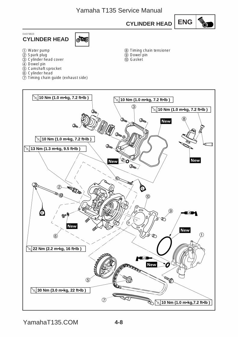
4-8
ENGCYLINDER HEAD
3
8
2
6
5
7
9
0
1
10 Nm (1.0 m•kg, 7.2 ft•lb ) 10 Nm (1.0 m•kg, 7.2 ft•lb )
10 Nm (1.0 m•kg, 7.2 ft•lb )
10 Nm (1.0 m•kg, 7.2 ft•lb )
13 Nm (1.3 m•kg, 9.5 ft•lb )
22 Nm (2.2 m•kg, 16 ft•lb )
30 Nm (3.0 m•kg, 22 ft•lb )
10 Nm (1.0 m•kg,7.2 ft•lb )
LS
E
E
EASF0023
CYLINDER HEAD
1 Water pump2 Spark plug3 Cylinder head cover4 Dowel pin5 Camshaft sprocket6 Cylinder head7 Timing chain guide (exhaust side)
8 Timing chain tensioner9 Dowel pin0 Gasket
5YP-F8197-E0_4_1 05.6.27 19:32 Page 8
Yamaha T135 Service Manual
YamahaT135.COM
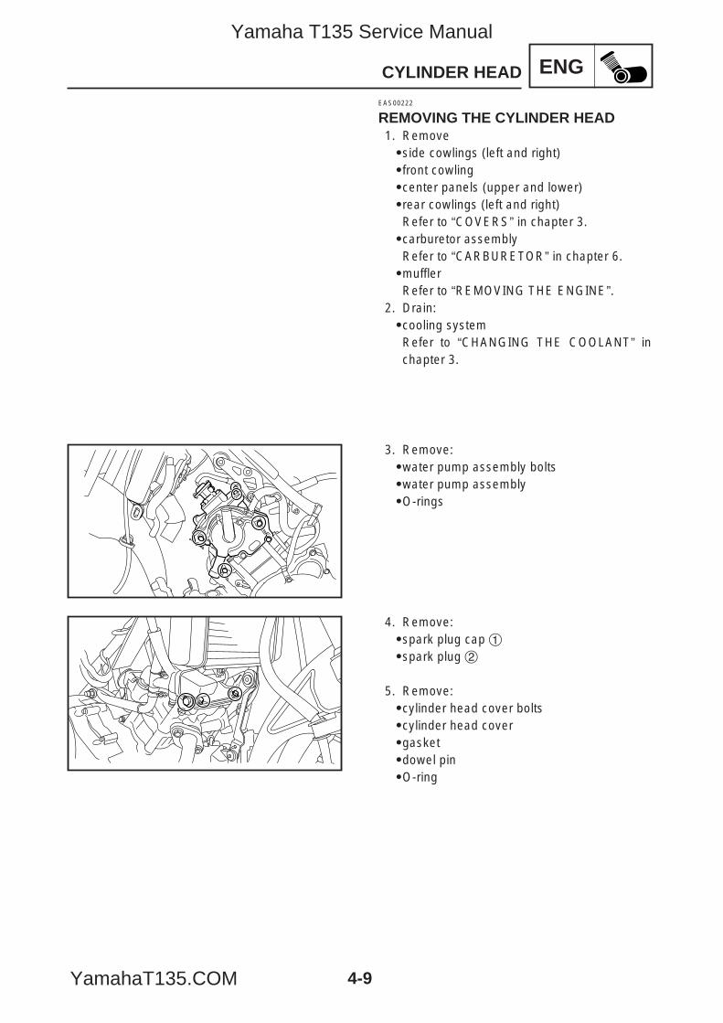
4-9
ENGCYLINDER HEAD
EAS00222
REMOVING THE CYLINDER HEAD1. Remove9side cowlings (left and right)9front cowling9center panels (upper and lower)9rear cowlings (left and right)Refer to “COVERS” in chapter 3.9carburetor assemblyRefer to “CARBURETOR” in chapter 6.9mufflerRefer to “REMOVING THE ENGINE”.
2. Drain:9cooling systemRefer to “CHANGING THE COOLANT” inchapter 3.
3. Remove:9water pump assembly bolts9water pump assembly9O-rings
4. Remove:9spark plug cap 19spark plug 2
5. Remove:9cylinder head cover bolts9cylinder head cover9gasket9dowel pin9O-ring
5YP-F8197-E0_4_1 05.6.27 19:32 Page 9
Yamaha T135 Service Manual
YamahaT135.COM
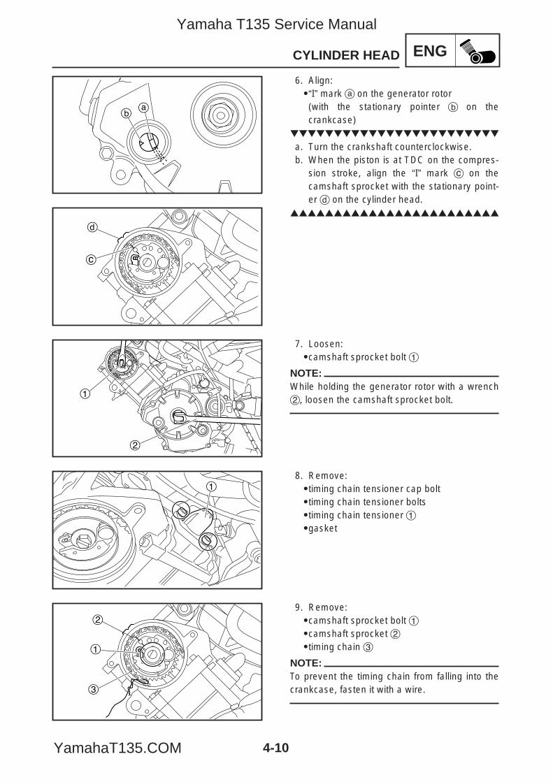
4-10
ENGCYLINDER HEAD
ab
c
d
1
2
1
1
2
3
6. Align:9“I” mark a on the generator rotor(with the stationary pointer b on thecrankcase)
a. Turn the crankshaft counterclockwise.b. When the piston is at TDC on the compres-
sion stroke, align the “I” mark c on thecamshaft sprocket with the stationary point-er d on the cylinder head.
7. Loosen:9camshaft sprocket bolt 1
NOTE:While holding the generator rotor with a wrench2, loosen the camshaft sprocket bolt.
8. Remove:9timing chain tensioner cap bolt9timing chain tensioner bolts9timing chain tensioner 19gasket
9. Remove:9camshaft sprocket bolt 19camshaft sprocket 29timing chain 3
NOTE:To prevent the timing chain from falling into thecrankcase, fasten it with a wire.
5YP-F8197-E0_4_1 05.6.27 19:32 Page 10
Yamaha T135 Service Manual
YamahaT135.COM
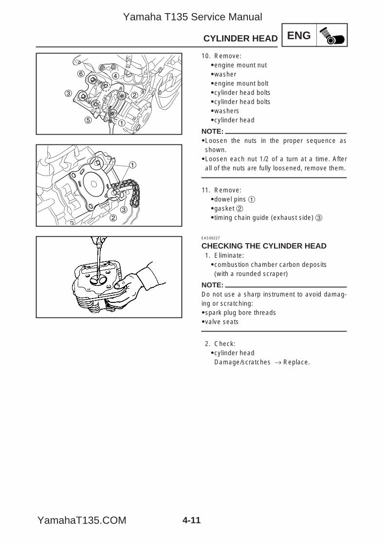
4-11
ENGCYLINDER HEAD
3
6
5
4
2
1
23
1
10. Remove:9engine mount nut9washer9engine mount bolt9cylinder head bolts9cylinder head bolts9washers9cylinder head
NOTE:9Loosen the nuts in the proper sequence asshown.9Loosen each nut 1/2 of a turn at a time. Afterall of the nuts are fully loosened, remove them.
11. Remove:9dowel pins 19gasket 29timing chain guide (exhaust side) 3
EAS00227
CHECKING THE CYLINDER HEAD1. Eliminate:9combustion chamber carbon deposits(with a rounded scraper)
NOTE:Do not use a sharp instrument to avoid damag-ing or scratching:9spark plug bore threads9valve seats
2. Check:9cylinder headDamage/scratches → Replace.
5YP-F8197-E0_4_1 05.6.28 12:49 Page 11
Yamaha T135 Service Manual
YamahaT135.COM
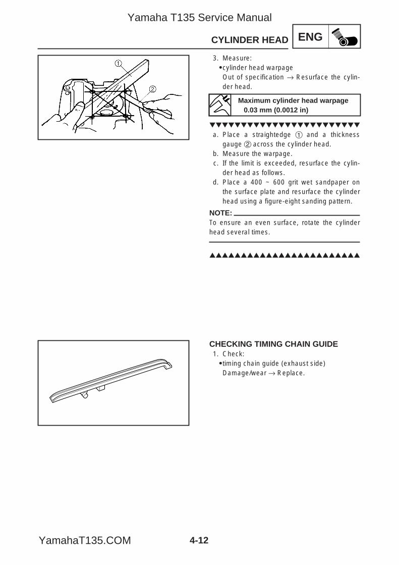
4-12
ENGCYLINDER HEAD
3. Measure:9cylinder head warpageOut of specification → Resurface the cylin-der head.
a. Place a straightedge 1 and a thicknessgauge 2 across the cylinder head.
b. Measure the warpage.c. If the limit is exceeded, resurface the cylin-
der head as follows.d. Place a 400 ~ 600 grit wet sandpaper on
the surface plate and resurface the cylinderhead using a figure-eight sanding pattern.
NOTE:To ensure an even surface, rotate the cylinderhead several times.
CHECKING TIMING CHAIN GUIDE1. Check:9timing chain guide (exhaust side)Damage/wear → Replace.
Maximum cylinder head warpage0.03 mm (0.0012 in)
5YP-F8197-E0_4_1 05.6.27 19:32 Page 12
Yamaha T135 Service Manual
YamahaT135.COM
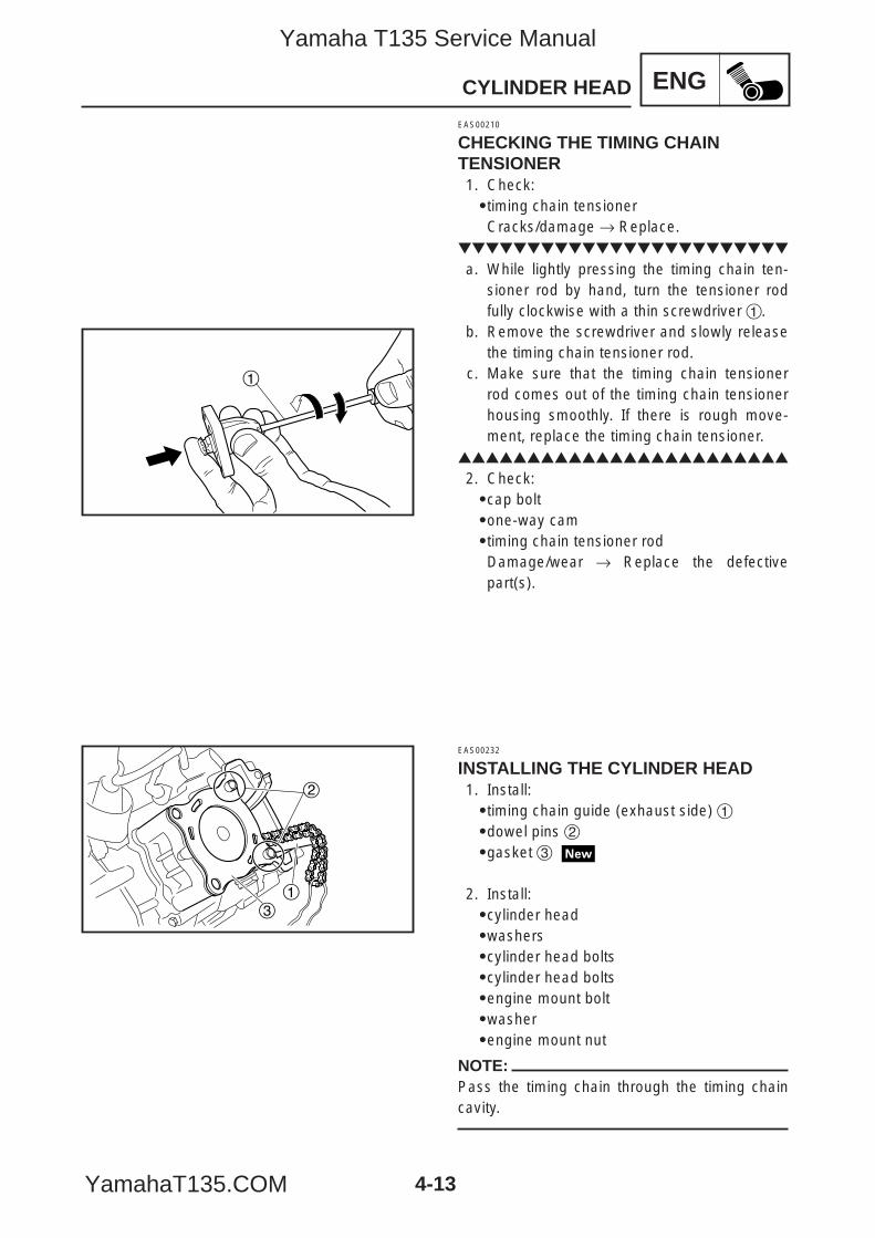
4-13
ENGCYLINDER HEAD
1
31
2
EAS00210
CHECKING THE TIMING CHAINTENSIONER1. Check:9timing chain tensionerCracks/damage → Replace.
a. While lightly pressing the timing chain ten-sioner rod by hand, turn the tensioner rodfully clockwise with a thin screwdriver 1.
b. Remove the screwdriver and slowly releasethe timing chain tensioner rod.
c. Make sure that the timing chain tensionerrod comes out of the timing chain tensionerhousing smoothly. If there is rough move-ment, replace the timing chain tensioner.
2. Check:9cap bolt9one-way cam9timing chain tensioner rodDamage/wear → Replace the defectivepart(s).
EAS00232
INSTALLING THE CYLINDER HEAD1. Install:9timing chain guide (exhaust side) 19dowel pins 29gasket 3
2. Install:9cylinder head9washers9cylinder head bolts9cylinder head bolts9engine mount bolt9washer9engine mount nut
NOTE:Pass the timing chain through the timing chaincavity.
5YP-F8197-E0_4_1 05.6.28 11:03 Page 13
Yamaha T135 Service Manual
YamahaT135.COM
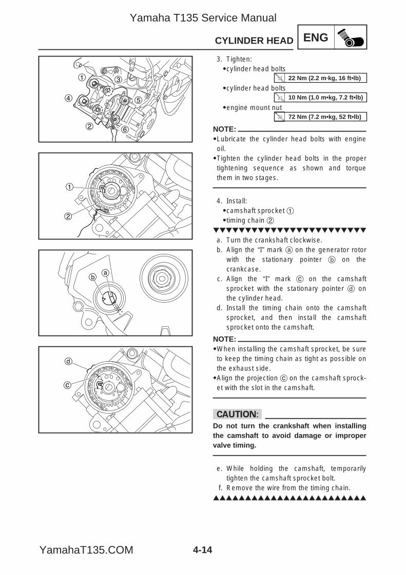
4-14
ENGCYLINDER HEAD
4
1
2
3
5
6
1
2
ab
c
d
3. Tighten:9cylinder head bolts
9cylinder head bolts
9engine mount nut
NOTE:9Lubricate the cylinder head bolts with engineoil.9Tighten the cylinder head bolts in the propertightening sequence as shown and torquethem in two stages.
4. Install:9camshaft sprocket 19timing chain 2
a. Turn the crankshaft clockwise.b. Align the “I” mark a on the generator rotor
with the stationary pointer b on thecrankcase.
c. Align the “I” mark c on the camshaftsprocket with the stationary pointer d onthe cylinder head.
d. Install the timing chain onto the camshaftsprocket, and then install the camshaftsprocket onto the camshaft.
NOTE:9When installing the camshaft sprocket, be sureto keep the timing chain as tight as possible onthe exhaust side.9Align the projection c on the camshaft sprock-et with the slot in the camshaft.
cCDo not turn the crankshaft when installingthe camshaft to avoid damage or impropervalve timing.
e. While holding the camshaft, temporarilytighten the camshaft sprocket bolt.
f. Remove the wire from the timing chain.
22 Nm (2.2 m·kg, 16 ft•lb)
10 Nm (1.0 m•kg, 7.2 ft•lb)
72 Nm (7.2 m•kg, 52 ft•lb)
5YP-F8197-E0_4_1 05.6.27 19:32 Page 14
Yamaha T135 Service Manual
YamahaT135.COM

4-15
ENGCYLINDER HEAD
1
2
5. Install:9timing chain tensioner
a. While lightly pressing the timing chain ten-sioner rod by hand, turn the tensioner rodfully clockwise with a thin screwdriver 1.
NOTE:Make sure that the tensioner rod has been fullyset clockwise.
b. Install the gasket and the timing chain ten-sioner 2 onto the cylinder.
wAlways use a new gasket.
NOTE:Apply the YAMAHA bond 1215 onto the bolts.
c. Turn the timing chain tensioner rod counter-clockwise with a thin screwdriver 1, makesure it releases, and then tighten the capbolt to specification.
6. Tighten:9camshaft sprocket bolt
cCBe sure to tighten the camshaft sprocketbolt to the specified torque to avoid the pos-sibility of the bolt coming loose and damag-ing the engine.
7. Turn:9crankshaft(several turns clockwise)
Timing chain tensioner bolt10 Nm (1.0 m·kg, 7.2 ft•lb)
30 Nm (3.0 m•kg, 22 ft•lb)
Yamaha bond No. 121590890-85505
5YP-F8197-E0_4_1 05.6.27 19:32 Page 15
Yamaha T135 Service Manual
YamahaT135.COM

4-16
ENGCYLINDER HEAD
ab
c
d
8. Check:9“I”mark aAlign the “I” mark on the generator rotorwith the stationary pointer b on thecrankcase.9“I”mark cAlign the “I”mark on the camshaft sprocketwith the stationary pointer d on the cylinderhead.Out of alignment → Correct.Refer to the installation steps above.
9. Measure:9valve clearanceOut of specification → Adjust.Refer to “ADJUSTING THE VALVE CLEAR-ANCE” in chapter 3.
10. Install:9O-rings 9water pump assembly9water pump assembly bolts
11. Install:9spark plug
12. Install:9intake manifold bolts9intake manifold with carburetor
10 Nm (1.0 m•kg, 7.2 ft•lb)
13 Nm (1.3 m•kg, 9.5 ft•lb)
10 Nm (1.0 m•kg, 7.2 ft•lb)
5YP-F8197-E0_4_1 05.6.27 19:32 Page 16
Yamaha T135 Service Manual
YamahaT135.COM
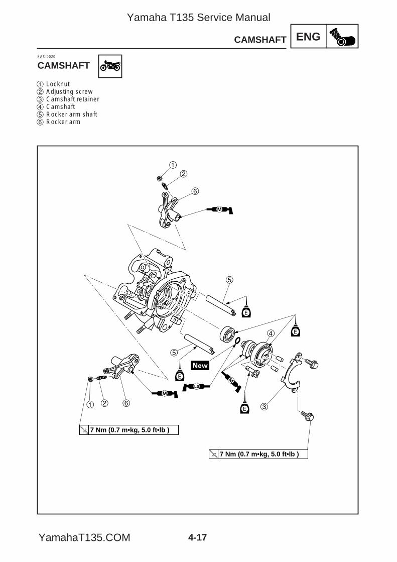
ENG
1 2 6
5
5
4
3
1
2
6
E
E
E
7 Nm (0.7 m•kg, 5.0 ft•lb )
7 Nm (0.7 m•kg, 5.0 ft•lb )
LS
E
4-17
CAMSHAFT
EASf0020
CAMSHAFT
1 Locknut2 Adjusting screw3 Camshaft retainer4 Camshaft5 Rocker arm shaft6 Rocker arm
5YP-F8197-E0_4_1 05.6.27 19:32 Page 17
Yamaha T135 Service Manual
YamahaT135.COM

4-18
ENGCAMSHAFT
1
2
1
1
2
EASF0022
REMOVING THE ROCKER ARMS ANDCAMSHAFTNOTE:Prior to remove the rocker arms and camshaft,remove the cylinder head.
1. Loosen:9locknuts 19adjusting screws 2
2. Remove:9camshaft retainer 1
3. Remove:9camshaft 1
NOTE:Screw an 8 mm bolt 2 into the threaded end ofthe camshaft and then pull out the camshaft.
4. Remove:9rocker arm shafts9rocker arms
5YP-F8197-E0_4_1 05.6.27 19:32 Page 18
Yamaha T135 Service Manual
YamahaT135.COM
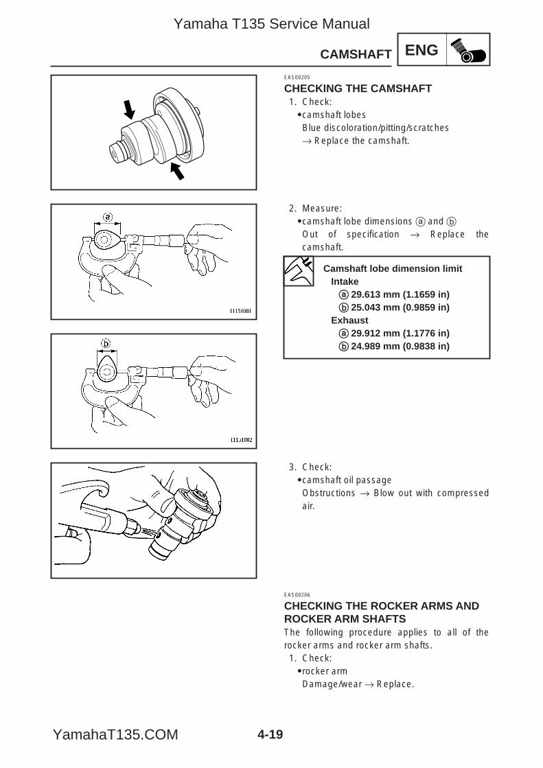
ENG
4-19
CAMSHAFT
EAS00205
CHECKING THE CAMSHAFT1. Check:9camshaft lobesBlue discoloration/pitting/scratches→ Replace the camshaft.
2. Measure:9camshaft lobe dimensions a and bOut of specification → Replace thecamshaft.
3. Check:9camshaft oil passageObstructions → Blow out with compressedair.
EAS00206
CHECKING THE ROCKER ARMS ANDROCKER ARM SHAFTSThe following procedure applies to all of therocker arms and rocker arm shafts.1. Check:9rocker armDamage/wear → Replace.
Camshaft lobe dimension limitIntakeaa 29.613 mm (1.1659 in)bb 25.043 mm (0.9859 in)
Exhaustaa 29.912 mm (1.1776 in)bb 24.989 mm (0.9838 in)
5YP-F8197-E0_4_1 05.6.27 19:32 Page 19
Yamaha T135 Service Manual
YamahaT135.COM
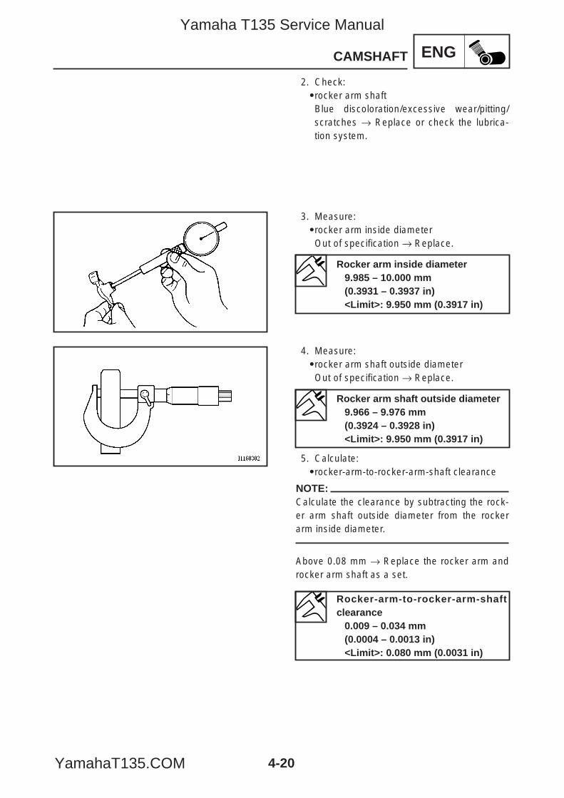
4-20
ENGCAMSHAFT
2. Check:9rocker arm shaftBlue discoloration/excessive wear/pitting/scratches → Replace or check the lubrica-tion system.
3. Measure:9rocker arm inside diameterOut of specification → Replace.
4. Measure:9rocker arm shaft outside diameterOut of specification → Replace.
5. Calculate:9rocker-arm-to-rocker-arm-shaft clearance
NOTE:Calculate the clearance by subtracting the rock-er arm shaft outside diameter from the rockerarm inside diameter.
Above 0.08 mm → Replace the rocker arm androcker arm shaft as a set.
Rocker arm inside diameter9.985 – 10.000 mm (0.3931 – 0.3937 in)<Limit>: 9.950 mm (0.3917 in)
Rocker arm shaft outside diameter9.966 – 9.976 mm (0.3924 – 0.3928 in)<Limit>: 9.950 mm (0.3917 in)
Rocker-arm-to-rocker-arm-shaftclearance
0.009 – 0.034 mm (0.0004 – 0.0013 in)<Limit>: 0.080 mm (0.0031 in)
5YP-F8197-E0_4_1 05.6.27 19:32 Page 20
Yamaha T135 Service Manual
YamahaT135.COM

4-21
ENGCAMSHAFT
EAS00207
CHECKING THE CAMSHAFTSPROCKET1. Check:9camshaft sprocketWorn more than 1/4 tooth a→ Replace thecamshaft sprocket and the timing chain as aset.
a 1/4 toothb Correct1 Timing chain2 Camshaft sprocket
a
1
EAS00219
INSTALLING THE CAMSHAFT ANDROCKER ARMS1. Lubricate:9camshaft journals
2. Lubricate:9rocker arm inside surface9camshaft oil passage
3. Install:9camshaft retainer 19camshaft retainer bolt
NOTE:Install the camshaft retainer with the bent endsfacing inward.
Recommended lubricantEngine oil
Recommended lubricantMolybdenum disulfide grease
7 Nm (0.7 m•kg, 5.0 ft•lb)
5YP-F8197-E0_4_1 05.6.27 19:32 Page 21
Yamaha T135 Service Manual
YamahaT135.COM

4-22
ENGVALVES AND VALVE SPRINGS
1
2
3
4
5
1
2
3
4
5
1 2 3 4 5
1 2 34 5
6
6
7
7
EASF0024
VALVES AND VALVE SPRINGS
1 Valve cotter2 Upper spring seat3 Valve spring4 Valve stem seal5 Lower spring seat6 Intake valve7 Exhaust valve
5YP-F8197-E0_4_1 05.6.27 19:32 Page 22
Yamaha T135 Service Manual
YamahaT135.COM

4-23
ENGVALVES AND VALVE SPRINGS
EASF0025
REMOVING THE VALVESNOTE:Prior to remove the valves, remove the cylinderhead, camshaft and rocker arms.
The following procedure applies to all of thevalves and related components.
NOTE:Before removing the internal parts of the cylin-der head (e.g., valves, valve springs, valveseats), make sure the valves properly seal.
1. Check:9valve sealingLeakage at the valve seat → Check thevalve face, valve seat, and valve seat width.Refer to “CHECKING THE VALVE SEATS”.
a. Pour a clean solvent a into the intake andexhaust ports.
b. Check that the valves properly seal.
NOTE:There should be no leakage at the valve seat1.
5YP-F8197-E0_4_1 05.6.27 19:32 Page 23
Yamaha T135 Service Manual
YamahaT135.COM
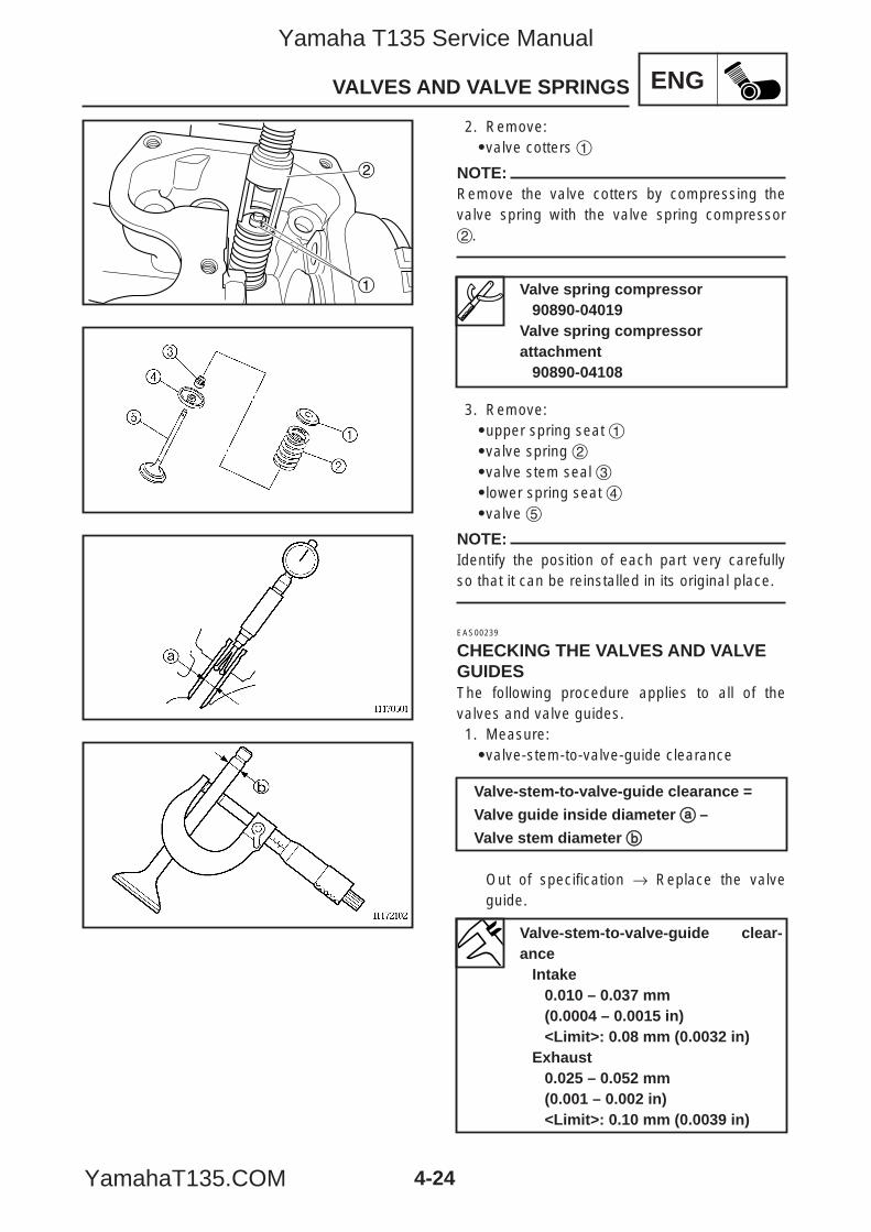
4-24
ENGVALVES AND VALVE SPRINGS
1
2
2. Remove:9valve cotters 1
NOTE:Remove the valve cotters by compressing thevalve spring with the valve spring compressor2.
3. Remove:9upper spring seat 19valve spring 29valve stem seal 39lower spring seat 49valve 5
NOTE:Identify the position of each part very carefullyso that it can be reinstalled in its original place.
EAS00239
CHECKING THE VALVES AND VALVEGUIDESThe following procedure applies to all of thevalves and valve guides.1. Measure:9valve-stem-to-valve-guide clearance
Out of specification → Replace the valveguide.
Valve spring compressor90890-04019
Valve spring compressor attachment
90890-04108
Valve-stem-to-valve-guide clearance =
Valve guide inside diameter aa –
Valve stem diameter bb
Valve-stem-to-valve-guide clear-ance
Intake0.010 – 0.037 mm (0.0004 – 0.0015 in)<Limit>: 0.08 mm (0.0032 in)
Exhaust0.025 – 0.052 mm(0.001 – 0.002 in)<Limit>: 0.10 mm (0.0039 in)
5YP-F8197-E0_4_1 05.6.27 19:32 Page 24
Yamaha T135 Service Manual
YamahaT135.COM
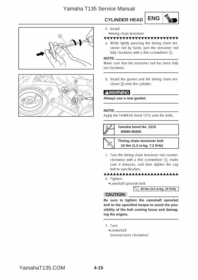
4-15
ENGCYLINDER HEAD
1
2
5. Install:9timing chain tensioner
a. While lightly pressing the timing chain ten-sioner rod by hand, turn the tensioner rodfully clockwise with a thin screwdriver 1.
NOTE:Make sure that the tensioner rod has been fullyset clockwise.
b. Install the gasket and the timing chain ten-sioner 2 onto the cylinder.
wAlways use a new gasket.
NOTE:Apply the YAMAHA bond 1215 onto the bolts.
c. Turn the timing chain tensioner rod counter-clockwise with a thin screwdriver 1, makesure it releases, and then tighten the capbolt to specification.
6. Tighten:9camshaft sprocket bolt
cCBe sure to tighten the camshaft sprocketbolt to the specified torque to avoid the pos-sibility of the bolt coming loose and damag-ing the engine.
7. Turn:9crankshaft(several turns clockwise)
Timing chain tensioner bolt10 Nm (1.0 m·kg, 7.2 ft•lb)
30 Nm (3.0 m•kg, 22 ft•lb)
Yamaha bond No. 121590890-85505
5YP-F8197-E0_4_1 05.6.27 19:32 Page 15
Yamaha T135 Service Manual
YamahaT135.COM
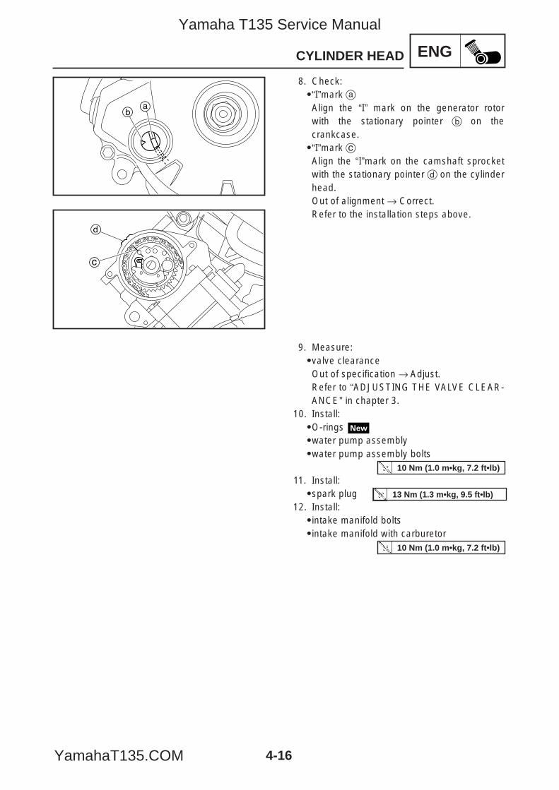
4-16
ENGCYLINDER HEAD
ab
c
d
8. Check:9“I”mark aAlign the “I” mark on the generator rotorwith the stationary pointer b on thecrankcase.9“I”mark cAlign the “I”mark on the camshaft sprocketwith the stationary pointer d on the cylinderhead.Out of alignment → Correct.Refer to the installation steps above.
9. Measure:9valve clearanceOut of specification → Adjust.Refer to “ADJUSTING THE VALVE CLEAR-ANCE” in chapter 3.
10. Install:9O-rings 9water pump assembly9water pump assembly bolts
11. Install:9spark plug
12. Install:9intake manifold bolts9intake manifold with carburetor
10 Nm (1.0 m•kg, 7.2 ft•lb)
13 Nm (1.3 m•kg, 9.5 ft•lb)
10 Nm (1.0 m•kg, 7.2 ft•lb)
5YP-F8197-E0_4_1 05.6.27 19:32 Page 16
Yamaha T135 Service Manual
YamahaT135.COM

ENG
1 2 6
5
5
4
3
1
2
6
E
E
E
7 Nm (0.7 m•kg, 5.0 ft•lb )
7 Nm (0.7 m•kg, 5.0 ft•lb )
LS
E
4-17
CAMSHAFT
EASf0020
CAMSHAFT
1 Locknut2 Adjusting screw3 Camshaft retainer4 Camshaft5 Rocker arm shaft6 Rocker arm
5YP-F8197-E0_4_1 05.6.27 19:32 Page 17
Yamaha T135 Service Manual
YamahaT135.COM
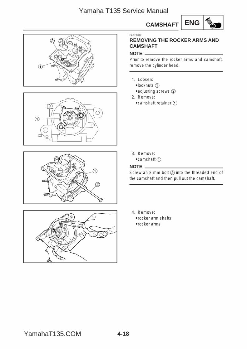
4-18
ENGCAMSHAFT
1
2
1
1
2
EASF0022
REMOVING THE ROCKER ARMS ANDCAMSHAFTNOTE:Prior to remove the rocker arms and camshaft,remove the cylinder head.
1. Loosen:9locknuts 19adjusting screws 2
2. Remove:9camshaft retainer 1
3. Remove:9camshaft 1
NOTE:Screw an 8 mm bolt 2 into the threaded end ofthe camshaft and then pull out the camshaft.
4. Remove:9rocker arm shafts9rocker arms
5YP-F8197-E0_4_1 05.6.27 19:32 Page 18
Yamaha T135 Service Manual
YamahaT135.COM

ENG
4-19
CAMSHAFT
EAS00205
CHECKING THE CAMSHAFT1. Check:9camshaft lobesBlue discoloration/pitting/scratches→ Replace the camshaft.
2. Measure:9camshaft lobe dimensions a and bOut of specification → Replace thecamshaft.
3. Check:9camshaft oil passageObstructions → Blow out with compressedair.
EAS00206
CHECKING THE ROCKER ARMS ANDROCKER ARM SHAFTSThe following procedure applies to all of therocker arms and rocker arm shafts.1. Check:9rocker armDamage/wear → Replace.
Camshaft lobe dimension limitIntakeaa 29.613 mm (1.1659 in)bb 25.043 mm (0.9859 in)
Exhaustaa 29.912 mm (1.1776 in)bb 24.989 mm (0.9838 in)
5YP-F8197-E0_4_1 05.6.27 19:32 Page 19
Yamaha T135 Service Manual
YamahaT135.COM

4-20
ENGCAMSHAFT
2. Check:9rocker arm shaftBlue discoloration/excessive wear/pitting/scratches → Replace or check the lubrica-tion system.
3. Measure:9rocker arm inside diameterOut of specification → Replace.
4. Measure:9rocker arm shaft outside diameterOut of specification → Replace.
5. Calculate:9rocker-arm-to-rocker-arm-shaft clearance
NOTE:Calculate the clearance by subtracting the rock-er arm shaft outside diameter from the rockerarm inside diameter.
Above 0.08 mm → Replace the rocker arm androcker arm shaft as a set.
Rocker arm inside diameter9.985 – 10.000 mm (0.3931 – 0.3937 in)<Limit>: 9.950 mm (0.3917 in)
Rocker arm shaft outside diameter9.966 – 9.976 mm (0.3924 – 0.3928 in)<Limit>: 9.950 mm (0.3917 in)
Rocker-arm-to-rocker-arm-shaftclearance
0.009 – 0.034 mm (0.0004 – 0.0013 in)<Limit>: 0.080 mm (0.0031 in)
5YP-F8197-E0_4_1 05.6.27 19:32 Page 20
Yamaha T135 Service Manual
YamahaT135.COM
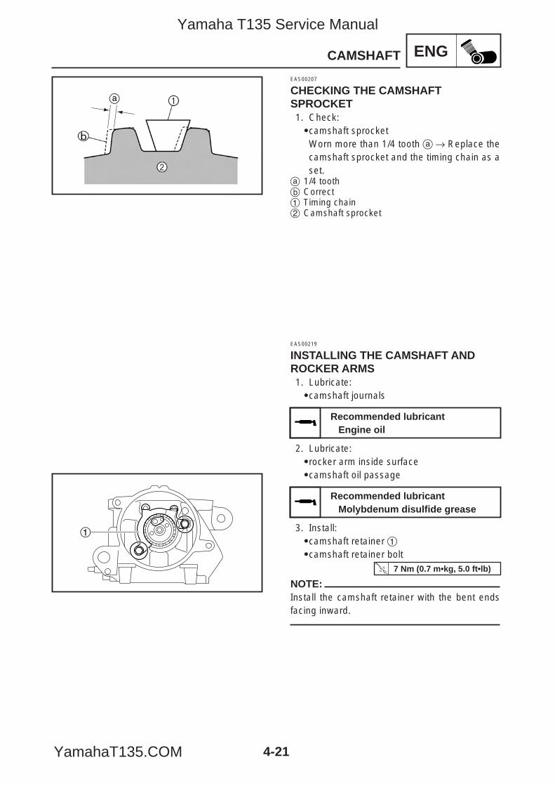
4-21
ENGCAMSHAFT
EAS00207
CHECKING THE CAMSHAFTSPROCKET1. Check:9camshaft sprocketWorn more than 1/4 tooth a→ Replace thecamshaft sprocket and the timing chain as aset.
a 1/4 toothb Correct1 Timing chain2 Camshaft sprocket
a
1
EAS00219
INSTALLING THE CAMSHAFT ANDROCKER ARMS1. Lubricate:9camshaft journals
2. Lubricate:9rocker arm inside surface9camshaft oil passage
3. Install:9camshaft retainer 19camshaft retainer bolt
NOTE:Install the camshaft retainer with the bent endsfacing inward.
Recommended lubricantEngine oil
Recommended lubricantMolybdenum disulfide grease
7 Nm (0.7 m•kg, 5.0 ft•lb)
5YP-F8197-E0_4_1 05.6.27 19:32 Page 21
Yamaha T135 Service Manual
YamahaT135.COM
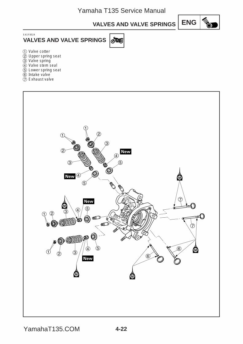
4-22
ENGVALVES AND VALVE SPRINGS
1
2
3
4
5
1
2
3
4
5
1 2 3 4 5
1 2 34 5
6
6
7
7
EASF0024
VALVES AND VALVE SPRINGS
1 Valve cotter2 Upper spring seat3 Valve spring4 Valve stem seal5 Lower spring seat6 Intake valve7 Exhaust valve
5YP-F8197-E0_4_1 05.6.27 19:32 Page 22
Yamaha T135 Service Manual
YamahaT135.COM
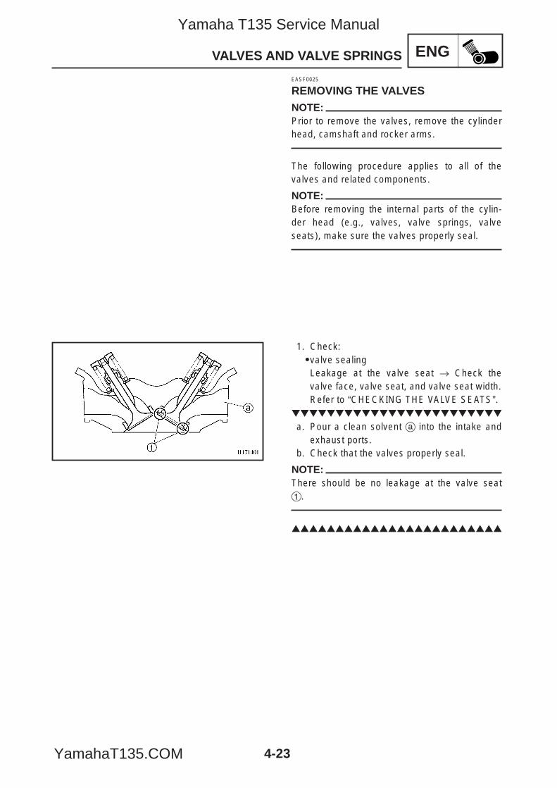
4-23
ENGVALVES AND VALVE SPRINGS
EASF0025
REMOVING THE VALVESNOTE:Prior to remove the valves, remove the cylinderhead, camshaft and rocker arms.
The following procedure applies to all of thevalves and related components.
NOTE:Before removing the internal parts of the cylin-der head (e.g., valves, valve springs, valveseats), make sure the valves properly seal.
1. Check:9valve sealingLeakage at the valve seat → Check thevalve face, valve seat, and valve seat width.Refer to “CHECKING THE VALVE SEATS”.
a. Pour a clean solvent a into the intake andexhaust ports.
b. Check that the valves properly seal.
NOTE:There should be no leakage at the valve seat1.
5YP-F8197-E0_4_1 05.6.27 19:32 Page 23
Yamaha T135 Service Manual
YamahaT135.COM

4-24
ENGVALVES AND VALVE SPRINGS
1
2
2. Remove:9valve cotters 1
NOTE:Remove the valve cotters by compressing thevalve spring with the valve spring compressor2.
3. Remove:9upper spring seat 19valve spring 29valve stem seal 39lower spring seat 49valve 5
NOTE:Identify the position of each part very carefullyso that it can be reinstalled in its original place.
EAS00239
CHECKING THE VALVES AND VALVEGUIDESThe following procedure applies to all of thevalves and valve guides.1. Measure:9valve-stem-to-valve-guide clearance
Out of specification → Replace the valveguide.
Valve spring compressor90890-04019
Valve spring compressor attachment
90890-04108
Valve-stem-to-valve-guide clearance =
Valve guide inside diameter aa –
Valve stem diameter bb
Valve-stem-to-valve-guide clear-ance
Intake0.010 – 0.037 mm (0.0004 – 0.0015 in)<Limit>: 0.08 mm (0.0032 in)
Exhaust0.025 – 0.052 mm(0.001 – 0.002 in)<Limit>: 0.10 mm (0.0039 in)
5YP-F8197-E0_4_1 05.6.27 19:32 Page 24
Yamaha T135 Service Manual
YamahaT135.COM
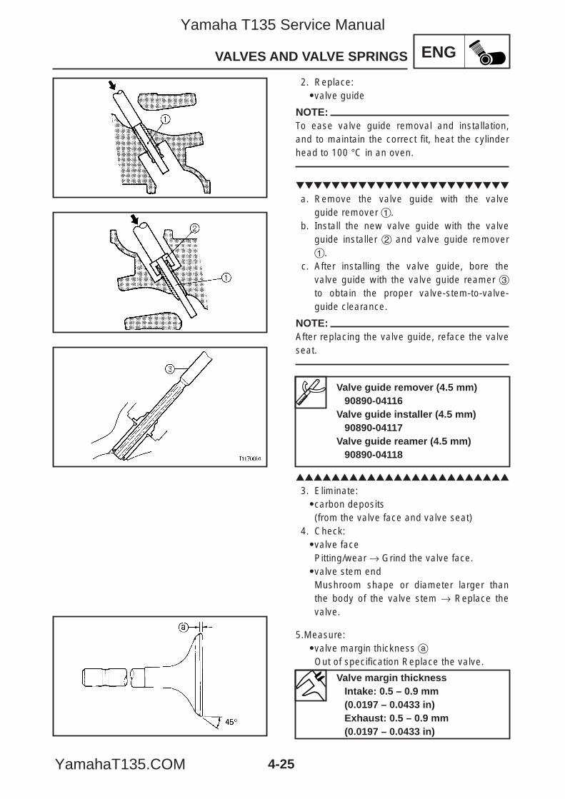
4-25
ENGVALVES AND VALVE SPRINGS
2. Replace:9valve guide
NOTE:To ease valve guide removal and installation,and to maintain the correct fit, heat the cylinderhead to 100 °C in an oven.
a. Remove the valve guide with the valveguide remover 1.
b. Install the new valve guide with the valveguide installer 2 and valve guide remover1.
c. After installing the valve guide, bore thevalve guide with the valve guide reamer 3to obtain the proper valve-stem-to-valve-guide clearance.
NOTE:After replacing the valve guide, reface the valveseat.
3. Eliminate:9carbon deposits(from the valve face and valve seat)
4. Check:9valve facePitting/wear → Grind the valve face.9valve stem endMushroom shape or diameter larger thanthe body of the valve stem → Replace thevalve.
5.Measure:9valve margin thickness aOut of specification Replace the valve.
Valve margin thicknessIntake: 0.5 – 0.9 mm(0.0197 – 0.0433 in)Exhaust: 0.5 – 0.9 mm(0.0197 – 0.0433 in)
Valve guide remover (4.5 mm)90890-04116
Valve guide installer (4.5 mm)90890-04117
Valve guide reamer (4.5 mm)90890-04118
5YP-F8197-E0_4_1 05.6.27 19:32 Page 25
Yamaha T135 Service Manual
YamahaT135.COM
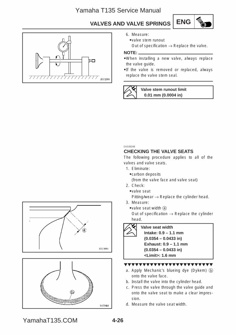
4-26
ENGVALVES AND VALVE SPRINGS
6. Measure:9valve stem runoutOut of specification → Replace the valve.
NOTE:9When installing a new valve, always replacethe valve guide.9If the valve is removed or replaced, alwaysreplace the valve stem seal.
EAS00240
CHECKING THE VALVE SEATSThe following procedure applies to all of thevalves and valve seats.1. Eliminate:9carbon deposits(from the valve face and valve seat)
2. Check:9valve seatPitting/wear → Replace the cylinder head.
3. Measure:9valve seat width aOut of specification → Replace the cylinderhead.
a. Apply Mechanic’s blueing dye (Dykem) bonto the valve face.
b. Install the valve into the cylinder head.c. Press the valve through the valve guide and
onto the valve seat to make a clear impres-sion.
d. Measure the valve seat width.
Valve stem runout limit0.01 mm (0.0004 in)
Valve seat widthIntake: 0.9 – 1.1 mm(0.0354 – 0.0433 in)Exhaust: 0.9 – 1.1 mm(0.0354 – 0.0433 in)<Limit>: 1.6 mm
5YP-F8197-E0_4_1 05.6.27 19:32 Page 26
Yamaha T135 Service Manual
YamahaT135.COM
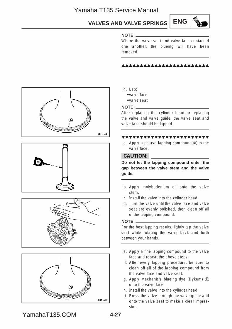
4-27
ENGVALVES AND VALVE SPRINGS
M
NOTE:Where the valve seat and valve face contactedone another, the blueing will have beenremoved.
4. Lap:9valve face9valve seat
NOTE:After replacing the cylinder head or replacingthe valve and valve guide, the valve seat andvalve face should be lapped.
a. Apply a coarse lapping compound a to thevalve face.
cCDo not let the lapping compound enter thegap between the valve stem and the valveguide.
b. Apply molybudenium oil onto the valvestem.
c. Install the valve into the cylinder head.d. Turn the valve until the valve face and valve
seat are evenly polished, then clean off allof the lapping compound.
NOTE:For the best lapping results, lightly tap the valveseat while rotating the valve back and forthbetween your hands.
e. Apply a fine lapping compound to the valveface and repeat the above steps.
f. After every lapping procedure, be sure toclean off all of the lapping compound fromthe valve face and valve seat.
g. Apply Mechanic’s blueing dye (Dykem) bonto the valve face.
h. Install the valve into the cylinder head.i. Press the valve through the valve guide and
onto the valve seat to make a clear impres-sion.
5YP-F8197-E0_4_1 05.6.27 19:32 Page 27
Yamaha T135 Service Manual
YamahaT135.COM
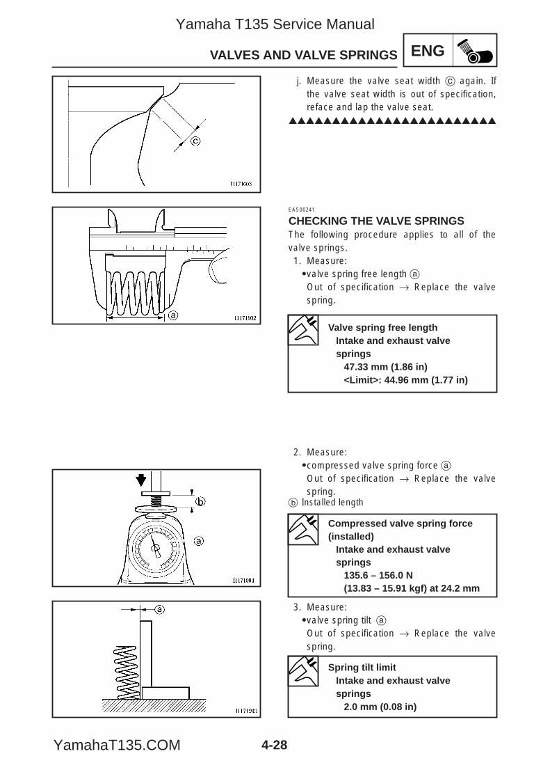
4-28
ENGVALVES AND VALVE SPRINGS
j. Measure the valve seat width c again. Ifthe valve seat width is out of specification,reface and lap the valve seat.
EAS00241
CHECKING THE VALVE SPRINGSThe following procedure applies to all of thevalve springs.1. Measure:9valve spring free length aOut of specification → Replace the valvespring.
2. Measure:9compressed valve spring force aOut of specification → Replace the valvespring.
b Installed length
3. Measure:9valve spring tilt aOut of specification → Replace the valvespring.
Valve spring free lengthIntake and exhaust valve springs
47.33 mm (1.86 in)<Limit>: 44.96 mm (1.77 in)
Compressed valve spring force(installed)
Intake and exhaust valvesprings
135.6 – 156.0 N(13.83 – 15.91 kgf) at 24.2 mm
Spring tilt limitIntake and exhaust valvesprings
2.0 mm (0.08 in)
5YP-F8197-E0_4_1 05.6.27 19:32 Page 28
Yamaha T135 Service Manual
YamahaT135.COM
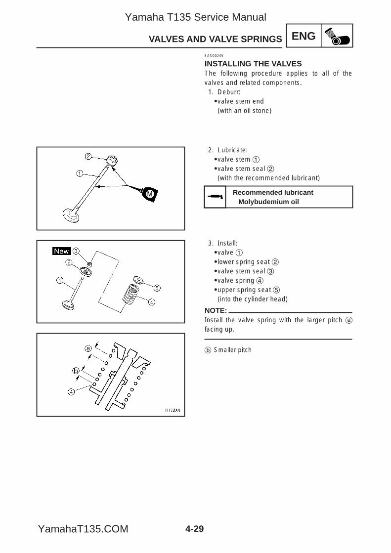
4-29
ENGVALVES AND VALVE SPRINGS
M
EAS00245
INSTALLING THE VALVESThe following procedure applies to all of thevalves and related components.1. Deburr:9valve stem end(with an oil stone)
2. Lubricate:9valve stem 19valve stem seal 2(with the recommended lubricant)
3. Install:9valve 19lower spring seat 29valve stem seal 39valve spring 49upper spring seat 5(into the cylinder head)
NOTE:Install the valve spring with the larger pitch afacing up.
b Smaller pitch
Recommended lubricantMolybudemium oil
5YP-F8197-E0_4_1 05.6.27 19:32 Page 29
Yamaha T135 Service Manual
YamahaT135.COM
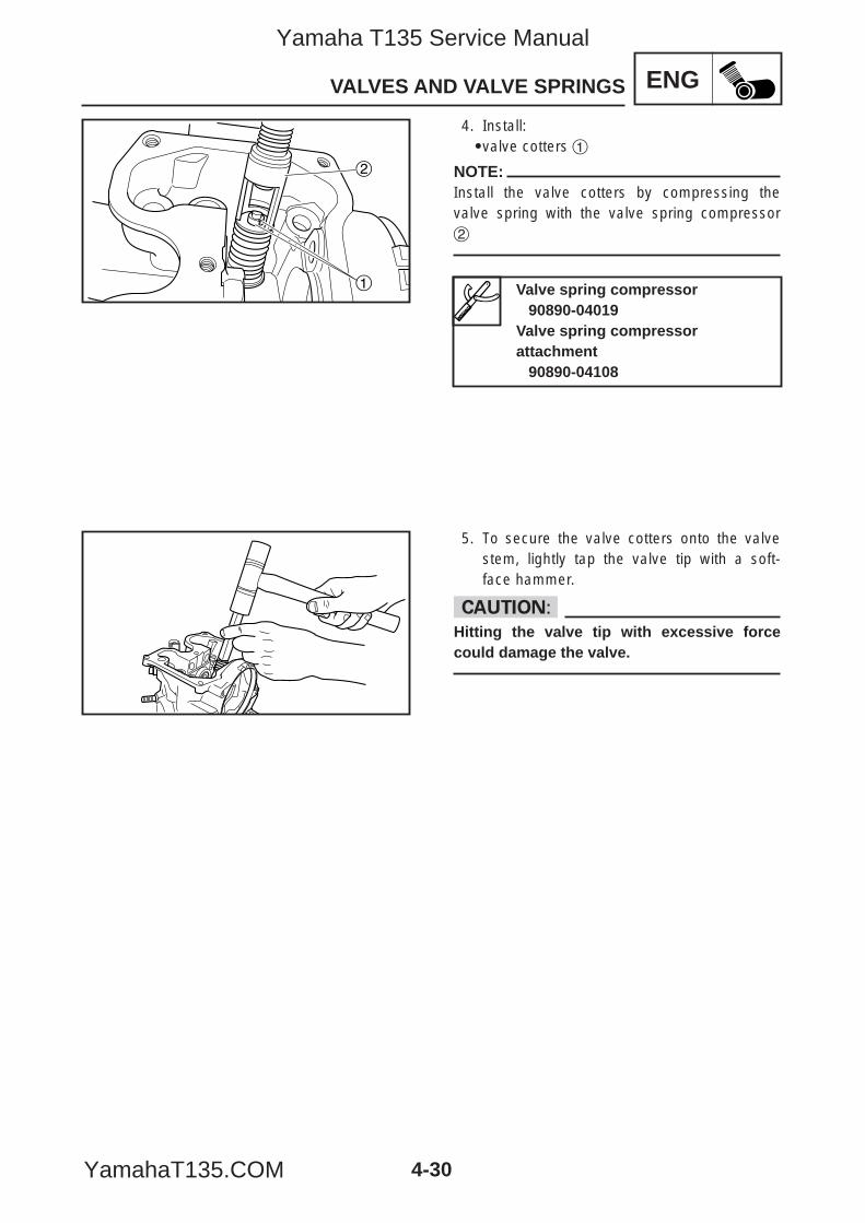
4-30
ENGVALVES AND VALVE SPRINGS
1
2
4. Install:9valve cotters 1
NOTE:Install the valve cotters by compressing thevalve spring with the valve spring compressor2
5. To secure the valve cotters onto the valvestem, lightly tap the valve tip with a soft-face hammer.
cCHitting the valve tip with excessive forcecould damage the valve.
Valve spring compressor90890-04019
Valve spring compressor attachment
90890-04108
5YP-F8197-E0_4_1 05.6.27 19:32 Page 30
Yamaha T135 Service Manual
YamahaT135.COM
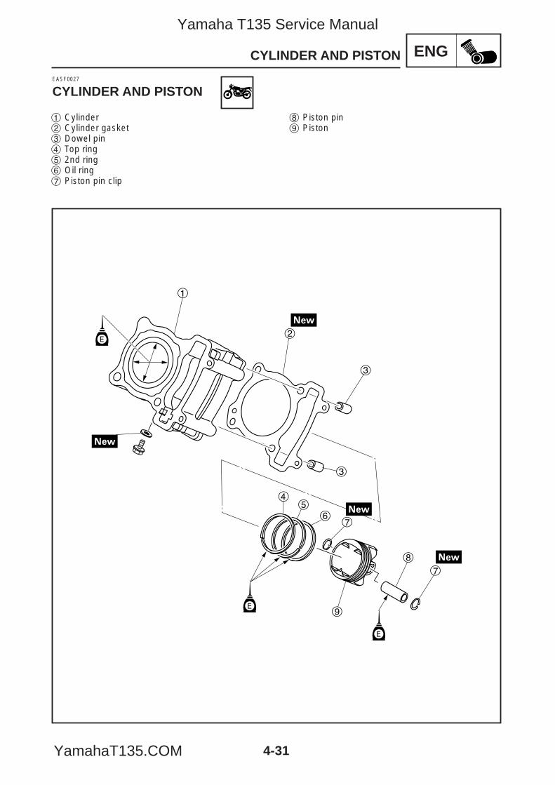
ENGCYLINDER AND PISTON
E
45
67
9
8
3
3
2
1
E
7
E
EASF0027
CYLINDER AND PISTON
1 Cylinder2 Cylinder gasket3 Dowel pin4 Top ring5 2nd ring6 Oil ring7 Piston pin clip
8 Piston pin9 Piston
4-31
5YP-F8197-E0_4_1 05.6.27 19:32 Page 31
Yamaha T135 Service Manual
YamahaT135.COM
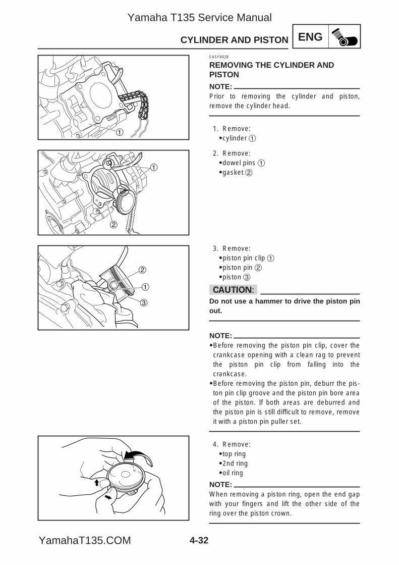
4-32
ENGCYLINDER AND PISTON
1
1
2
2
1
3
EASF0028
REMOVING THE CYLINDER ANDPISTONNOTE:Prior to removing the cylinder and piston,remove the cylinder head.
1. Remove:9cylinder 1
2. Remove:9dowel pins 19gasket 2
3. Remove:9piston pin clip 19piston pin 29piston 3
cCDo not use a hammer to drive the piston pinout.
NOTE:9Before removing the piston pin clip, cover thecrankcase opening with a clean rag to preventthe piston pin clip from falling into thecrankcase.9Before removing the piston pin, deburr the pis-ton pin clip groove and the piston pin bore areaof the piston. If both areas are deburred andthe piston pin is still difficult to remove, removeit with a piston pin puller set.
4. Remove:9top ring92nd ring9oil ring
NOTE:When removing a piston ring, open the end gapwith your fingers and lift the other side of thering over the piston crown.
5YP-F8197-E0_4_1 05.6.28 11:03 Page 32
Yamaha T135 Service Manual
YamahaT135.COM
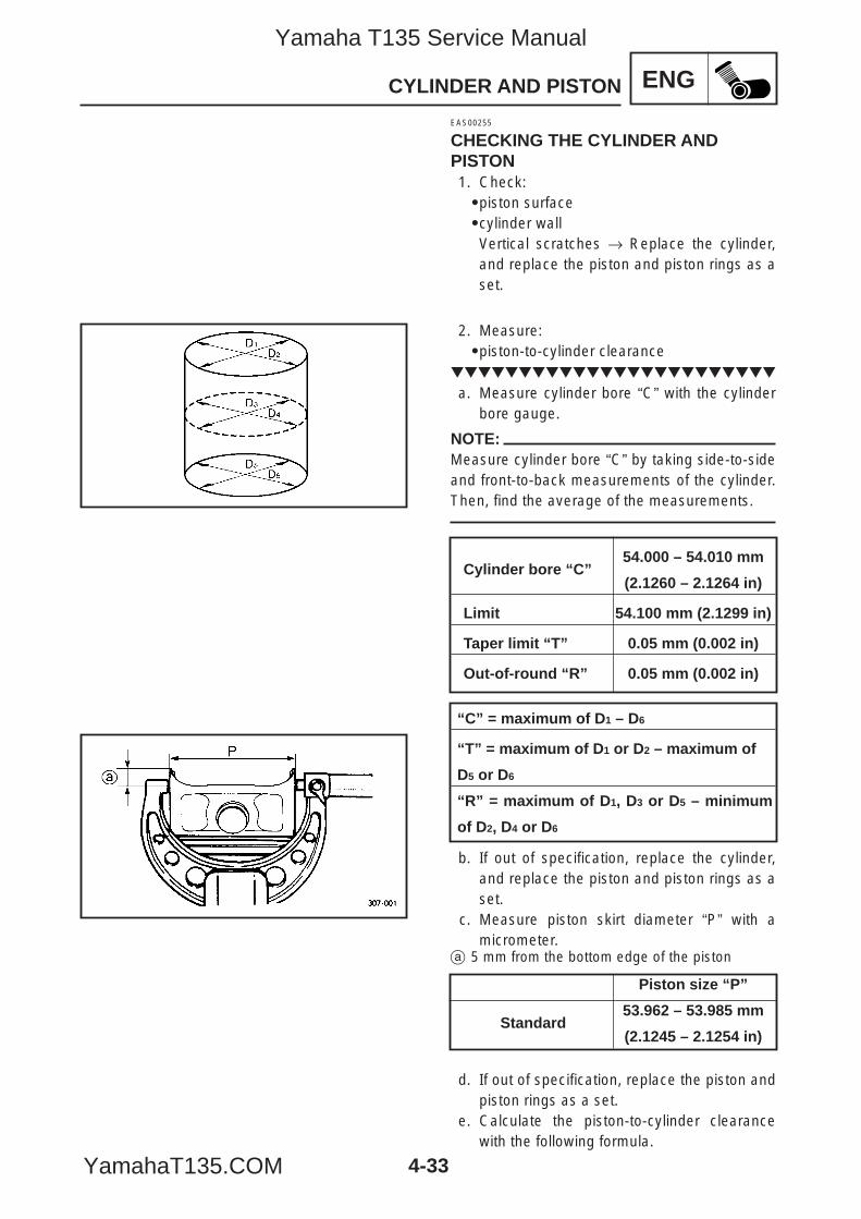
4-33
ENGCYLINDER AND PISTON
EAS00255
CHECKING THE CYLINDER ANDPISTON1. Check:9piston surface9cylinder wallVertical scratches → Replace the cylinder,and replace the piston and piston rings as aset.
2. Measure:9piston-to-cylinder clearance
a. Measure cylinder bore “C” with the cylinderbore gauge.
NOTE:Measure cylinder bore “C” by taking side-to-sideand front-to-back measurements of the cylinder.Then, find the average of the measurements.
b. If out of specification, replace the cylinder,and replace the piston and piston rings as aset.
c. Measure piston skirt diameter “P” with amicrometer.
a 5 mm from the bottom edge of the piston
d. If out of specification, replace the piston andpiston rings as a set.
e. Calculate the piston-to-cylinder clearancewith the following formula.
Cylinder bore “C”54.000 – 54.010 mm
(2.1260 – 2.1264 in)
Limit 54.100 mm (2.1299 in)
Taper limit “T” 0.05 mm (0.002 in)
Out-of-round “R” 0.05 mm (0.002 in)
“C” = maximum of D1 – D6
“T” = maximum of D1 or D2 – maximum of
D5 or D6
“R” = maximum of D1, D3 or D5 – minimum
of D2, D4 or D6
Piston size “P”
Standard53.962 – 53.985 mm
(2.1245 – 2.1254 in)
5YP-F8197-E0_4_1 05.6.27 19:32 Page 33
Yamaha T135 Service Manual
YamahaT135.COM
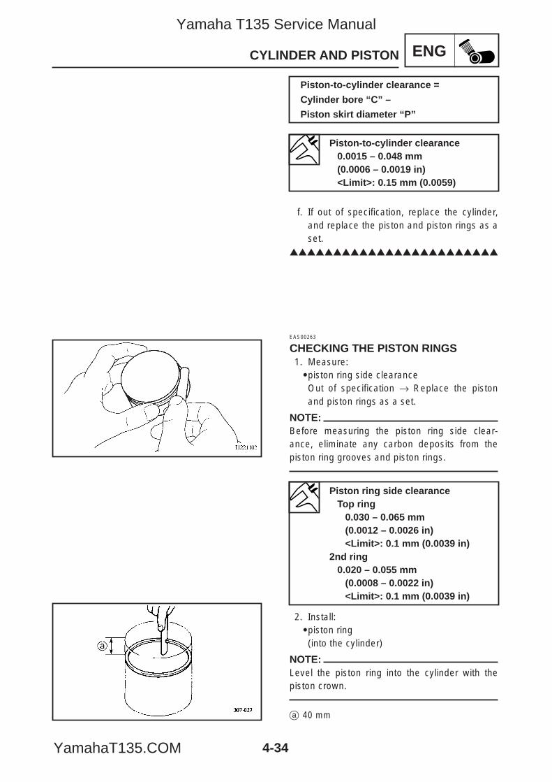
4-34
ENGCYLINDER AND PISTON
f. If out of specification, replace the cylinder,and replace the piston and piston rings as aset.
EAS00263
CHECKING THE PISTON RINGS1. Measure:9piston ring side clearanceOut of specification → Replace the pistonand piston rings as a set.
NOTE:Before measuring the piston ring side clear-ance, eliminate any carbon deposits from thepiston ring grooves and piston rings.
2. Install:9piston ring(into the cylinder)
NOTE:Level the piston ring into the cylinder with thepiston crown.
a 40 mm
Piston-to-cylinder clearance0.0015 – 0.048 mm(0.0006 – 0.0019 in)<Limit>: 0.15 mm (0.0059)
Piston-to-cylinder clearance =
Cylinder bore “C” –
Piston skirt diameter “P”
Piston ring side clearanceTop ring
0.030 – 0.065 mm (0.0012 – 0.0026 in)<Limit>: 0.1 mm (0.0039 in)
2nd ring0.020 – 0.055 mm
(0.0008 – 0.0022 in)<Limit>: 0.1 mm (0.0039 in)
5YP-F8197-E0_4_1 05.6.27 19:32 Page 34
Yamaha T135 Service Manual
YamahaT135.COM
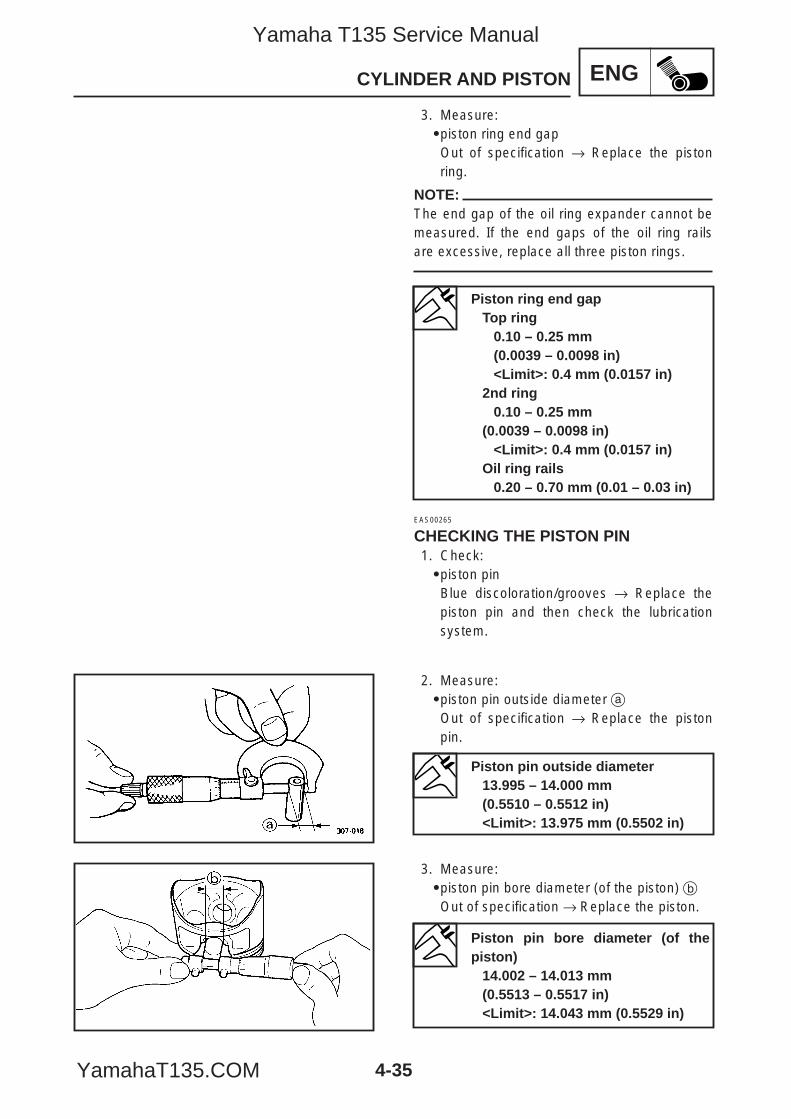
4-35
ENGCYLINDER AND PISTON
3. Measure:9piston ring end gapOut of specification → Replace the pistonring.
NOTE:The end gap of the oil ring expander cannot bemeasured. If the end gaps of the oil ring railsare excessive, replace all three piston rings.
EAS00265
CHECKING THE PISTON PIN1. Check:9piston pinBlue discoloration/grooves → Replace thepiston pin and then check the lubricationsystem.
2. Measure:9piston pin outside diameter aOut of specification → Replace the pistonpin.
3. Measure:9piston pin bore diameter (of the piston) bOut of specification → Replace the piston.
Piston ring end gapTop ring
0.10 – 0.25 mm(0.0039 – 0.0098 in)<Limit>: 0.4 mm (0.0157 in)
2nd ring0.10 – 0.25 mm
(0.0039 – 0.0098 in)<Limit>: 0.4 mm (0.0157 in)
Oil ring rails0.20 – 0.70 mm (0.01 – 0.03 in)
Piston pin outside diameter13.995 – 14.000 mm(0.5510 – 0.5512 in)<Limit>: 13.975 mm (0.5502 in)
Piston pin bore diameter (of thepiston)
14.002 – 14.013 mm(0.5513 – 0.5517 in)<Limit>: 14.043 mm (0.5529 in)
5YP-F8197-E0_4_1 05.6.27 19:32 Page 35
Yamaha T135 Service Manual
YamahaT135.COM
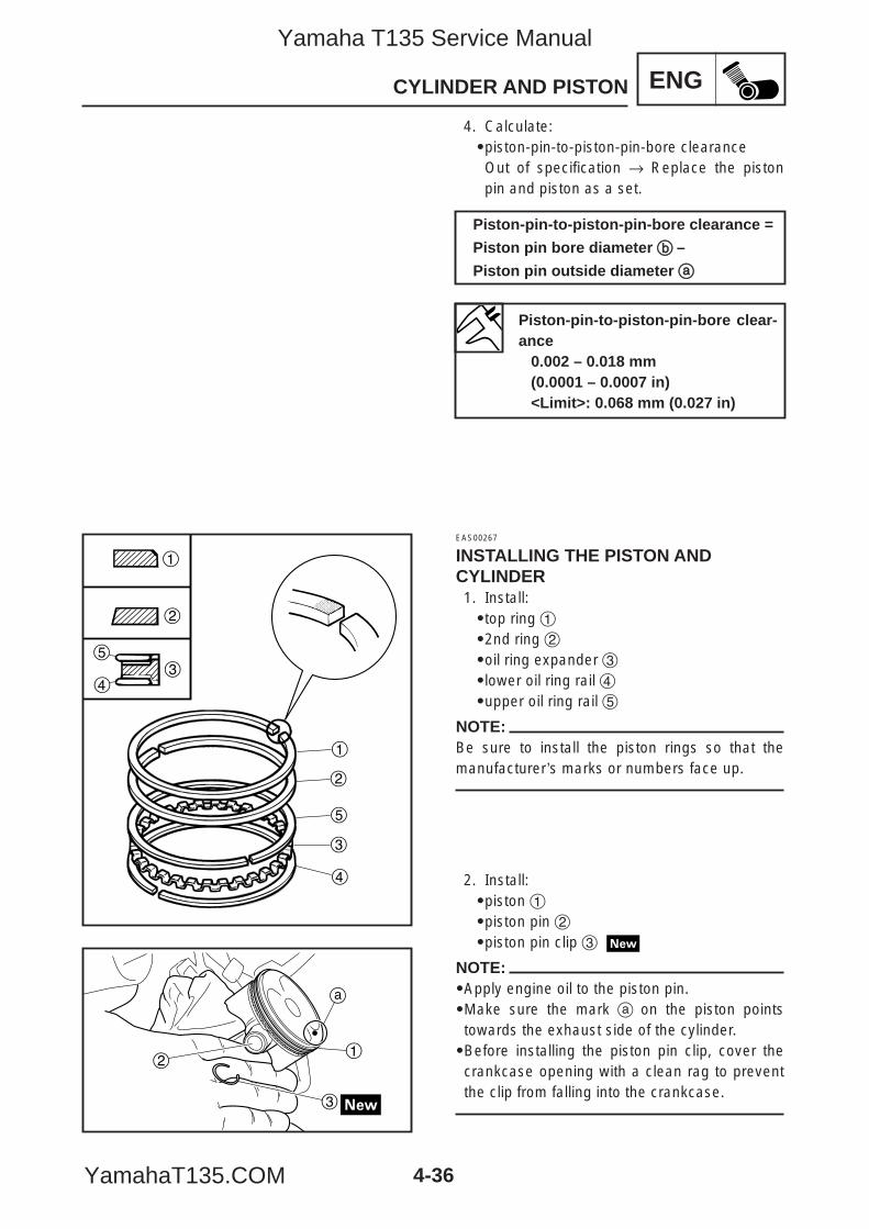
4-36
ENGCYLINDER AND PISTON
1
2
35
4
1
2
5
3
4
1
3
2
a
4. Calculate:9piston-pin-to-piston-pin-bore clearanceOut of specification → Replace the pistonpin and piston as a set.
EAS00267
INSTALLING THE PISTON ANDCYLINDER1. Install:9top ring 192nd ring 29oil ring expander 39lower oil ring rail 49upper oil ring rail 5
NOTE:Be sure to install the piston rings so that themanufacturer’s marks or numbers face up.
2. Install:9piston 19piston pin 29piston pin clip 3
NOTE:9Apply engine oil to the piston pin.9Make sure the mark a on the piston pointstowards the exhaust side of the cylinder.9Before installing the piston pin clip, cover thecrankcase opening with a clean rag to preventthe clip from falling into the crankcase.
Piston-pin-to-piston-pin-bore clearance =
Piston pin bore diameter bb –
Piston pin outside diameter aa
Piston-pin-to-piston-pin-bore clear-ance
0.002 – 0.018 mm(0.0001 – 0.0007 in)<Limit>: 0.068 mm (0.027 in)
5YP-F8197-E0_4_1 05.6.27 19:32 Page 36
Yamaha T135 Service Manual
YamahaT135.COM
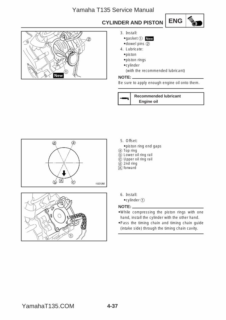
4-37
ENGCYLINDER AND PISTON
2
1
1
3. Install:9gasket 1
9dowel pins 24. Lubricate:9piston9piston rings9cylinder(with the recommended lubricant)
NOTE:Be sure to apply enough engine oil onto them.
5. Offset:9piston ring end gaps
a Top ringb Lower oil ring railc Upper oil ring raild 2nd ringå forward
6. Install:9cylinder 1
NOTE:9While compressing the piston rings with onehand, install the cylinder with the other hand.9Pass the timing chain and timing chain guide(intake side) through the timing chain cavity.
Recommended lubricantEngine oil
5YP-F8197-E0_4_1 05.6.28 11:03 Page 37
Yamaha T135 Service Manual
YamahaT135.COM
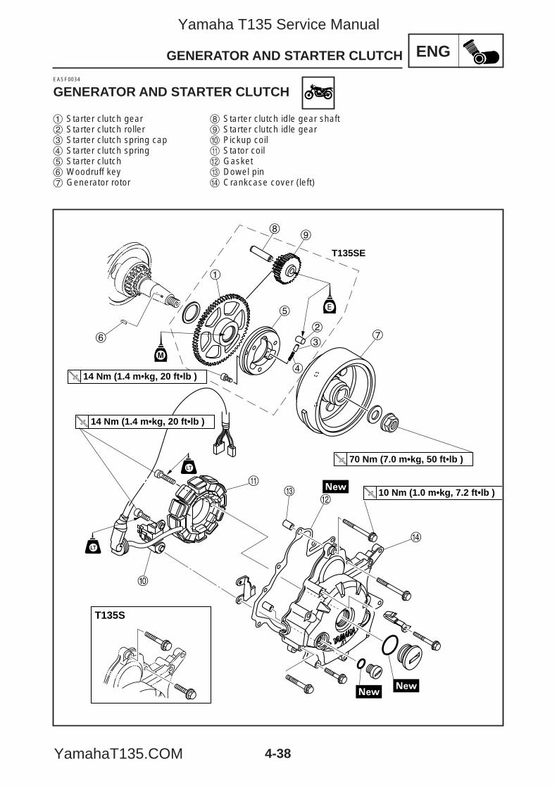
4-38
ENGGENERATOR AND STARTER CLUTCH
T135S
1
89
5
2
3
4
7
ew
r
q
0
6
14 Nm (1.4 m•kg, 20 ft•lb )
70 Nm (7.0 m•kg, 50 ft•lb )
10 Nm (1.0 m•kg, 7.2 ft•lb )
14 Nm (1.4 m•kg, 20 ft•lb )
E
T135SE
EASF0034
GENERATOR AND STARTER CLUTCH
1 Starter clutch gear2 Starter clutch roller3 Starter clutch spring cap4 Starter clutch spring5 Starter clutch6 Woodruff key7 Generator rotor
8 Starter clutch idle gear shaft9 Starter clutch idle gear0 Pickup coilq Stator coilw Gaskete Dowel pinr Crankcase cover (left)
5YP-F8197-E0_4_1 05.6.27 19:32 Page 38
Yamaha T135 Service Manual
YamahaT135.COM
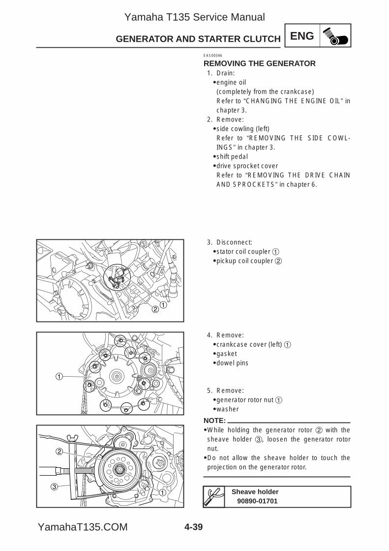
4-39
ENGGENERATOR AND STARTER CLUTCH
21
1
31
2
EAS00346
REMOVING THE GENERATOR1. Drain:9engine oil(completely from the crankcase)Refer to “CHANGING THE ENGINE OIL” inchapter 3.
2. Remove:9side cowling (left)Refer to “REMOVING THE SIDE COWL-INGS” in chapter 3.9shift pedal9drive sprocket coverRefer to “REMOVING THE DRIVE CHAINAND SPROCKETS” in chapter 6.
3. Disconnect:9stator coil coupler 19pickup coil coupler 2
5. Remove:9generator rotor nut 19washer
NOTE:9While holding the generator rotor 2 with thesheave holder 3, loosen the generator rotornut.9Do not allow the sheave holder to touch theprojection on the generator rotor.
Sheave holder90890-01701
4. Remove:9crankcase cover (left) 19gasket9dowel pins
5YP-F8197-E0_4_1 05.6.27 19:32 Page 39
Yamaha T135 Service Manual
YamahaT135.COM
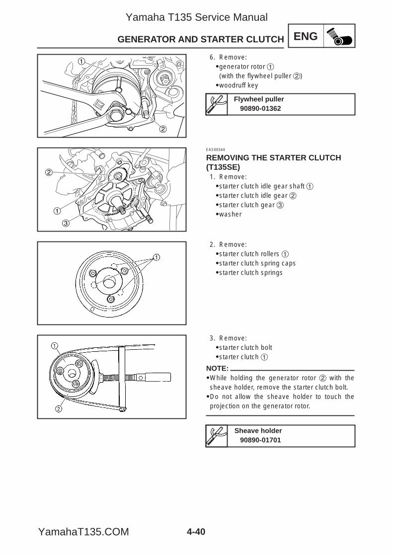
4-40
ENGGENERATOR AND STARTER CLUTCH
2
1
2
1
3
6. Remove:9generator rotor 1(with the flywheel puller 2)9woodruff key
EAS00344
REMOVING THE STARTER CLUTCH(T135SE)1. Remove:9starter clutch idle gear shaft 19starter clutch idle gear 29starter clutch gear 39washer
2. Remove:9starter clutch rollers 19starter clutch spring caps9starter clutch springs
3. Remove:9starter clutch bolt9starter clutch 1
NOTE:9While holding the generator rotor 2 with thesheave holder, remove the starter clutch bolt.9Do not allow the sheave holder to touch theprojection on the generator rotor.
Flywheel puller90890-01362
Sheave holder90890-01701
5YP-F8197-E0_4_1 05.6.27 19:32 Page 40
Yamaha T135 Service Manual
YamahaT135.COM
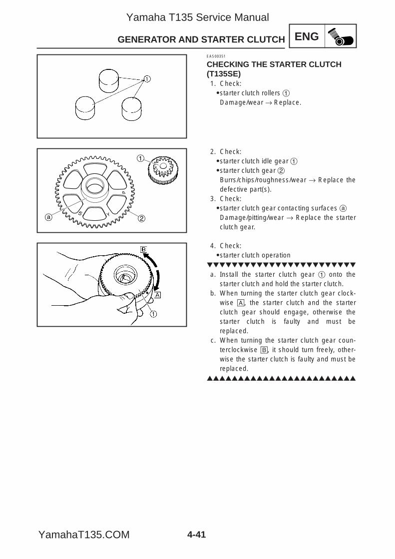
4-41
ENGGENERATOR AND STARTER CLUTCH
2
1
a
EAS00351
CHECKING THE STARTER CLUTCH(T135SE)1. Check:9starter clutch rollers 1Damage/wear → Replace.
2. Check:9starter clutch idle gear 19starter clutch gear 2Burrs/chips/roughness/wear → Replace thedefective part(s).
3. Check:9starter clutch gear contacting surfaces aDamage/pitting/wear → Replace the starterclutch gear.
4. Check:9starter clutch operation
a. Install the starter clutch gear 1 onto thestarter clutch and hold the starter clutch.
b. When turning the starter clutch gear clock-wise å, the starter clutch and the starterclutch gear should engage, otherwise thestarter clutch is faulty and must bereplaced.
c. When turning the starter clutch gear coun-terclockwise ∫, it should turn freely, other-wise the starter clutch is faulty and must bereplaced.
5YP-F8197-E0_4_1 05.6.27 19:32 Page 41
Yamaha T135 Service Manual
YamahaT135.COM
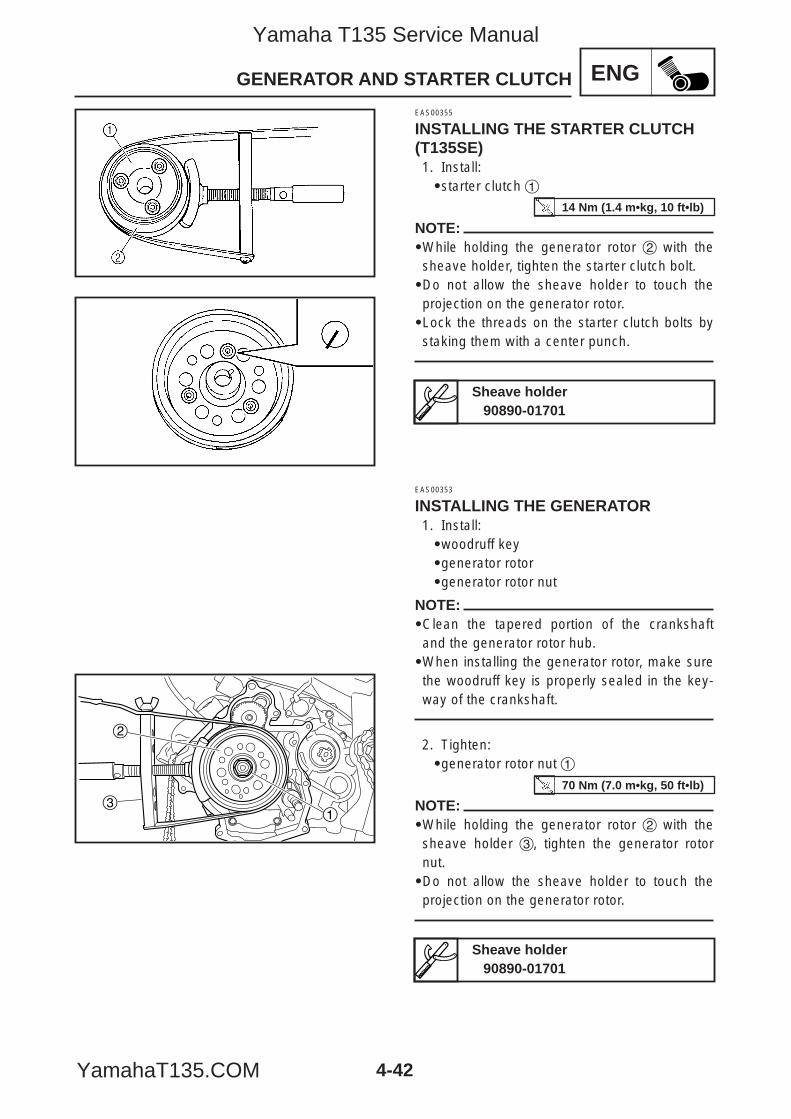
4-42
ENGGENERATOR AND STARTER CLUTCH
31
2
EAS00355
INSTALLING THE STARTER CLUTCH(T135SE)1. Install:9starter clutch 1
NOTE:9While holding the generator rotor 2 with thesheave holder, tighten the starter clutch bolt.9Do not allow the sheave holder to touch theprojection on the generator rotor.9Lock the threads on the starter clutch bolts bystaking them with a center punch.
EAS00353
INSTALLING THE GENERATOR1. Install:9woodruff key9generator rotor9generator rotor nut
NOTE:9Clean the tapered portion of the crankshaftand the generator rotor hub.9When installing the generator rotor, make surethe woodruff key is properly sealed in the key-way of the crankshaft.
2. Tighten:9generator rotor nut 1
NOTE:9While holding the generator rotor 2 with thesheave holder 3, tighten the generator rotornut.9Do not allow the sheave holder to touch theprojection on the generator rotor.
Sheave holder90890-01701
Sheave holder90890-01701
14 Nm (1.4 m•kg, 10 ft•lb)
70 Nm (7.0 m•kg, 50 ft•lb)
5YP-F8197-E0_4_1 05.6.27 19:32 Page 42
Yamaha T135 Service Manual
YamahaT135.COM
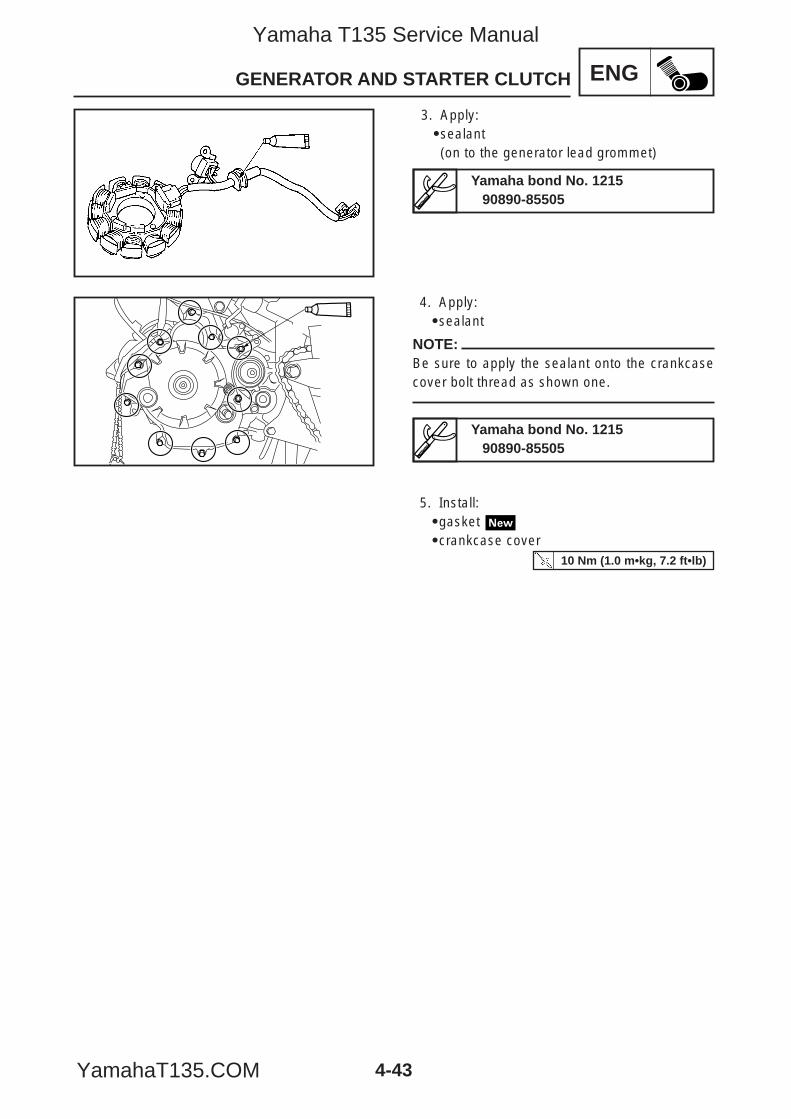
4. Apply:9sealant
NOTE:Be sure to apply the sealant onto the crankcasecover bolt thread as shown one.
5. Install:9gasket 9crankcase cover
4-43
ENGGENERATOR AND STARTER CLUTCH
3. Apply:9sealant(on to the generator lead grommet)
Yamaha bond No. 121590890-85505
Yamaha bond No. 121590890-85505
10 Nm (1.0 m•kg, 7.2 ft•lb)
5YP-F8197-E0_4_1 05.6.27 19:32 Page 43
Yamaha T135 Service Manual
YamahaT135.COM
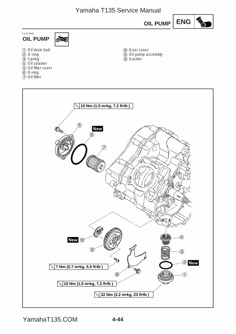
ENG
5
7
6
0
9
8
4
3
2
1
10 Nm (1.0 m•kg, 7.2 ft•lb )
10 Nm (1.0 m•kg, 7.2 ft•lb )
32 Nm (3.2 m•kg, 23 ft•lb )
7 Nm (0.7 m•kg, 5.0 ft•lb )
4-44
OIL PUMP
1 Oil drain bolt2 O-ring3 Spring4 Oil strainer5 Oil filter cover6 O-ring7 Oil filter
8 Gear cover9 Oil pump assembly0 Gasket
EASF0035
OIL PUMP
5YP-F8197-E0_4_1 05.6.27 19:32 Page 44
Yamaha T135 Service Manual
YamahaT135.COM
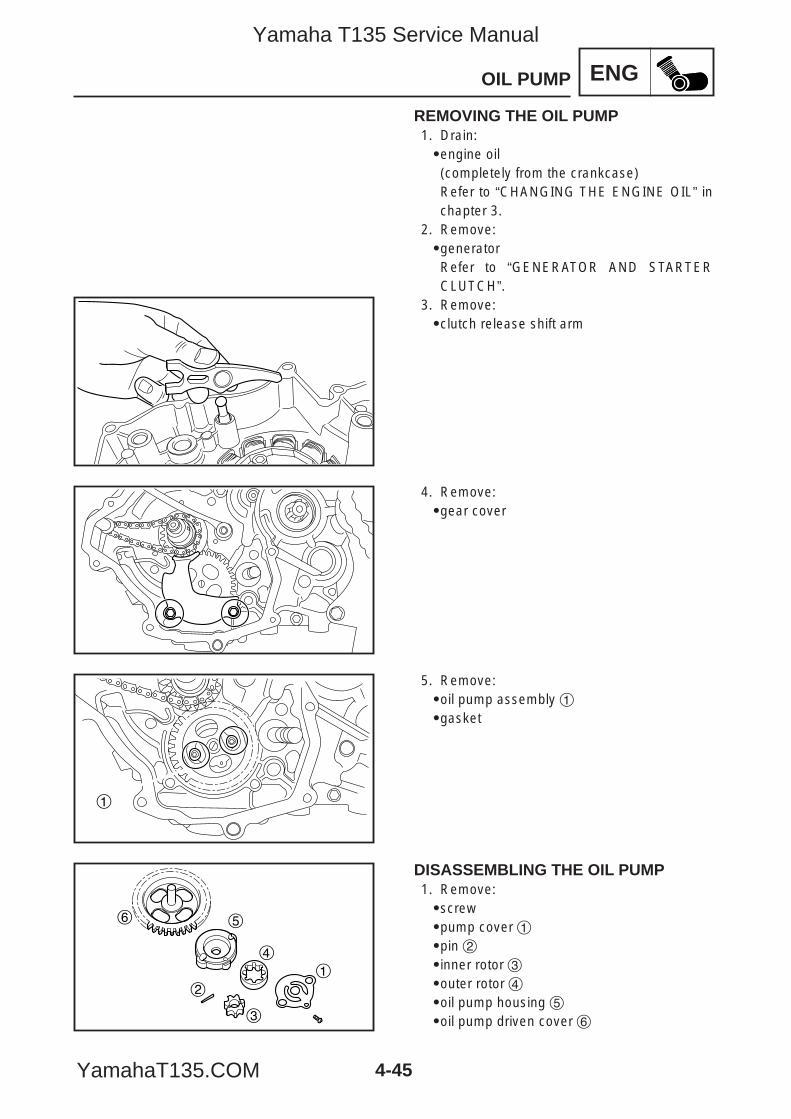
ENG
1
1
2
3
4
56
4-45
OIL PUMP
REMOVING THE OIL PUMP1. Drain:9engine oil(completely from the crankcase)Refer to “CHANGING THE ENGINE OIL” inchapter 3.
2. Remove:9generatorRefer to “GENERATOR AND STARTERCLUTCH”.
3. Remove:9clutch release shift arm
4. Remove:9gear cover
5. Remove:9oil pump assembly 19gasket
DISASSEMBLING THE OIL PUMP1. Remove:9screw9pump cover 19pin 29inner rotor 39outer rotor 49oil pump housing 59oil pump driven cover 6
5YP-F8197-E0_4_1 05.6.27 19:32 Page 45
Yamaha T135 Service Manual
YamahaT135.COM
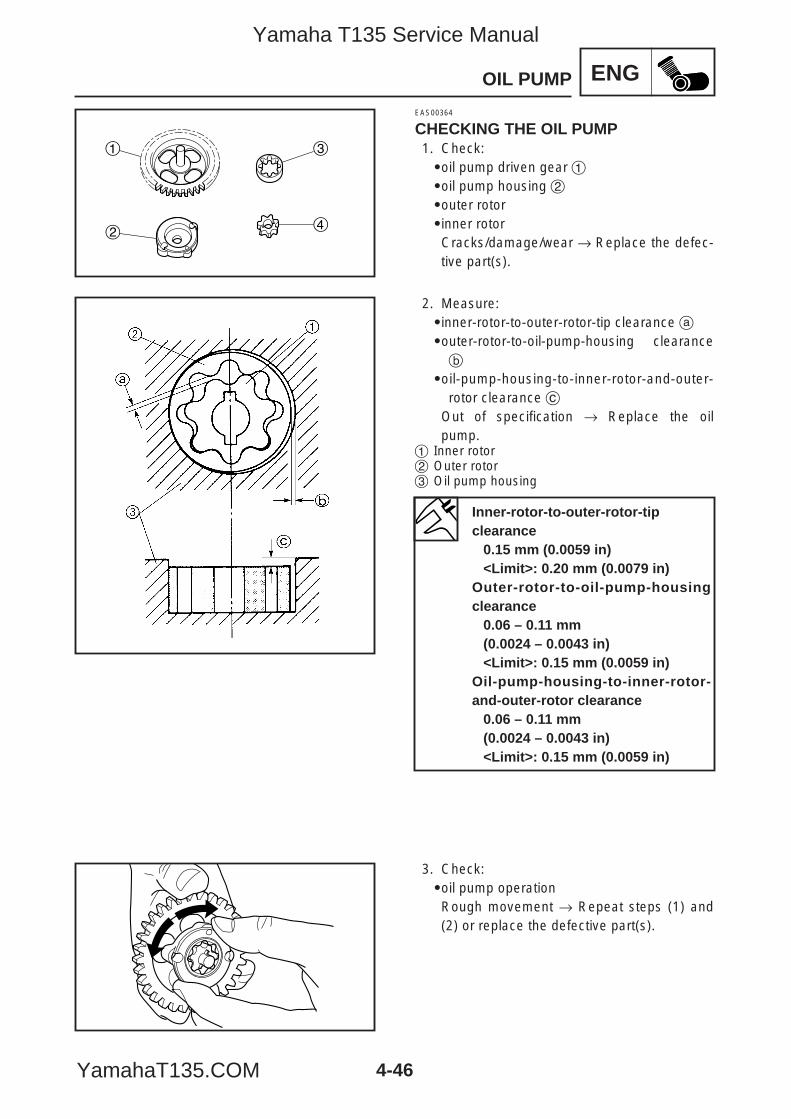
ENG
1
2
3
4
4-46
OIL PUMP
EAS00364
CHECKING THE OIL PUMP1. Check:9oil pump driven gear 19oil pump housing 29outer rotor9inner rotorCracks/damage/wear → Replace the defec-tive part(s).
2. Measure:9inner-rotor-to-outer-rotor-tip clearance a9outer-rotor-to-oil-pump-housing clearanceb
9oil-pump-housing-to-inner-rotor-and-outer-rotor clearance c
Out of specification → Replace the oilpump.
1 Inner rotor2 Outer rotor3 Oil pump housing
3. Check:9oil pump operationRough movement → Repeat steps (1) and(2) or replace the defective part(s).
Inner-rotor-to-outer-rotor-tip clearance
0.15 mm (0.0059 in)<Limit>: 0.20 mm (0.0079 in)
Outer-rotor-to-oil-pump-housingclearance
0.06 – 0.11 mm(0.0024 – 0.0043 in)<Limit>: 0.15 mm (0.0059 in)
Oil-pump-housing-to-inner-rotor-and-outer-rotor clearance
0.06 – 0.11 mm(0.0024 – 0.0043 in)<Limit>: 0.15 mm (0.0059 in)
5YP-F8197-E0_4_1 05.6.27 19:32 Page 46
Yamaha T135 Service Manual
YamahaT135.COM
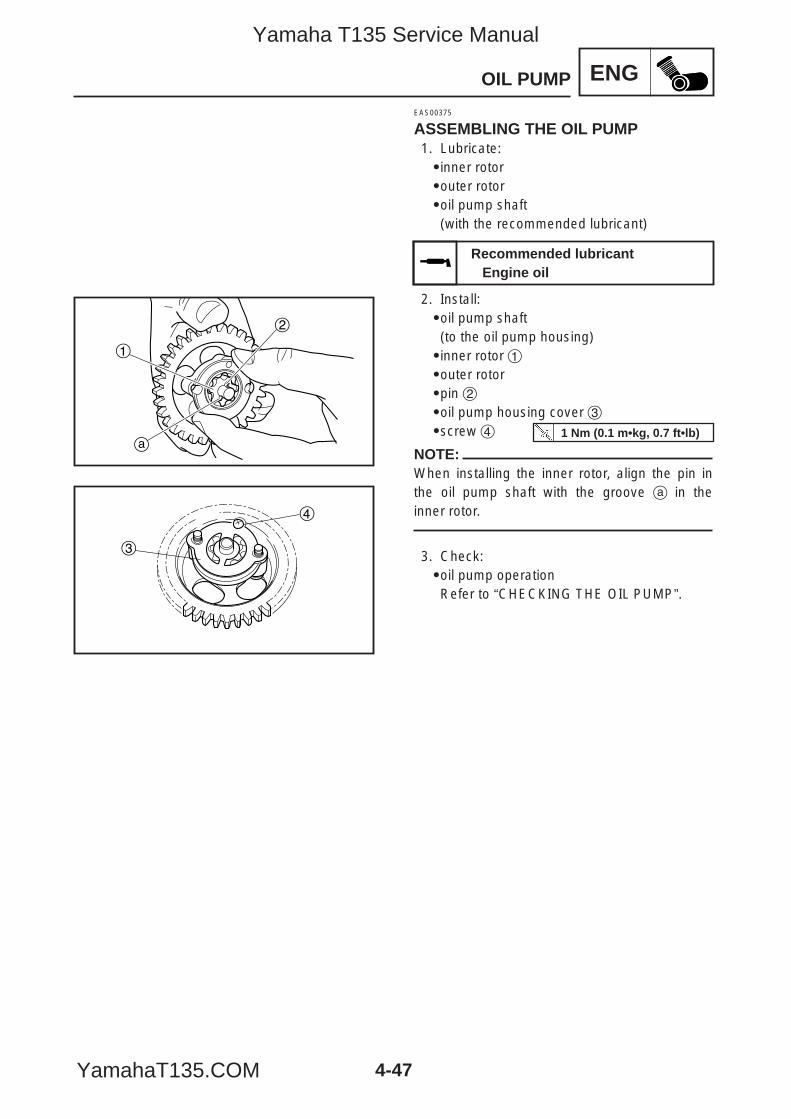
ENG
1
2
a
4
3
4-47
OIL PUMP
EAS00375
ASSEMBLING THE OIL PUMP1. Lubricate:9inner rotor9outer rotor9oil pump shaft(with the recommended lubricant)
2. Install:9oil pump shaft(to the oil pump housing)9inner rotor 19outer rotor9pin 29oil pump housing cover 39screw 4
NOTE:When installing the inner rotor, align the pin inthe oil pump shaft with the groove a in theinner rotor.
3. Check:9oil pump operationRefer to “CHECKING THE OIL PUMP”.
Recommended lubricantEngine oil
1 Nm (0.1 m•kg, 0.7 ft•lb)
5YP-F8197-E0_4_1 05.6.27 19:32 Page 47
Yamaha T135 Service Manual
YamahaT135.COM
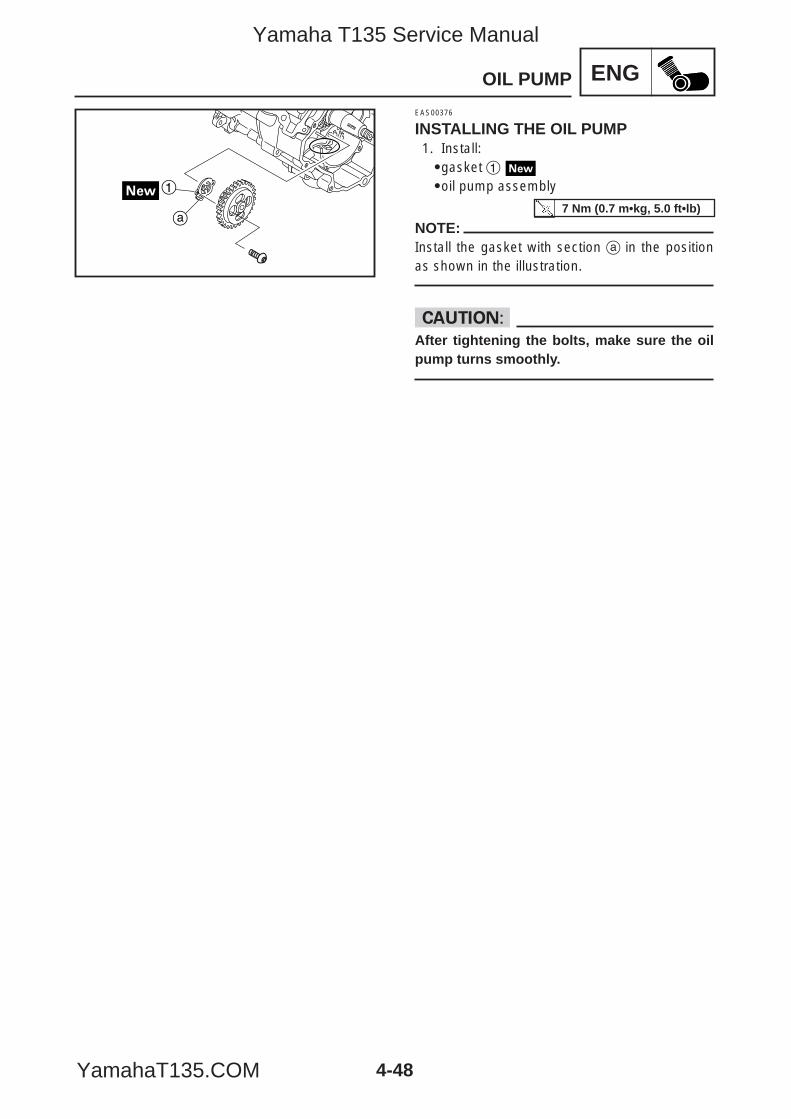
ENG
4-48
OIL PUMP
1
a
EAS00376
INSTALLING THE OIL PUMP1. Install:9gasket 19oil pump assembly
NOTE:Install the gasket with section a in the positionas shown in the illustration.
cCAfter tightening the bolts, make sure the oilpump turns smoothly.
7 Nm (0.7 m•kg, 5.0 ft•lb)
5YP-F8197-E0_4_1 05.6.27 19:32 Page 48
Yamaha T135 Service Manual
YamahaT135.COM
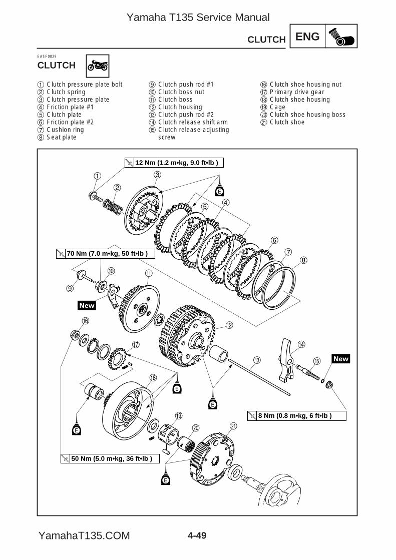
4-49
ENG
3
45
1
2
78
q0
9
w
e
r
t
ap
o
i
u
y
70 Nm (7.0 m•kg, 50 ft•lb )
12 Nm (1.2 m•kg, 9.0 ft•lb )
8 Nm (0.8 m•kg, 6 ft•lb )
50 Nm (5.0 m•kg, 36 ft•lb )
E
E
E
E
E
6
CLUTCH
EASF0029
CLUTCH
1 Clutch pressure plate bolt2 Clutch spring3 Clutch pressure plate4 Friction plate #15 Clutch plate6 Friction plate #27 Cushion ring8 Seat plate
9 Clutch push rod #10 Clutch boss nutq Clutch bossw Clutch housinge Clutch push rod #2r Clutch release shift armt Clutch release adjusting
screw
y Clutch shoe housing nutu Primary drive geari Clutch shoe housingo Cagep Clutch shoe housing bossa Clutch shoe
5YP-F8197-E0_4_1 05.6.27 19:32 Page 49
Yamaha T135 Service Manual
YamahaT135.COM
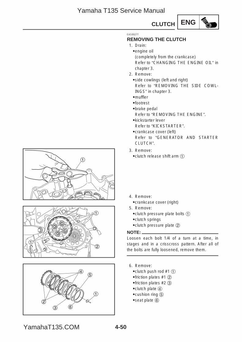
ENG
1
1
1
2
1
2
45
63
4-50
CLUTCH
EAS00277
REMOVING THE CLUTCH1. Drain:9engine oil(completely from the crankcase)Refer to “CHANGING THE ENGINE OIL” inchapter 3.
2. Remove:9side cowlings (left and right)Refer to “REMOVING THE SIDE COWL-INGS” in chapter 3.9muffler9footrest9brake pedalRefer to “REMOVING THE ENGINE”.9kickstarter leverRefer to “KICKSTARTER”.9crankcase cover (left)Refer to “GENERATOR AND STARTERCLUTCH”.
5. Remove:9clutch pressure plate bolts 19clutch springs9clutch pressure plate 2
NOTE:Loosen each bolt 1/4 of a turn at a time, instages and in a crisscross pattern. After all ofthe bolts are fully loosened, remove them.
6. Remove:9clutch push rod #1 19friction plates #1 29friction plates #2 39clutch plate 49cushion ring 59seat plate 6
3. Remove:9clutch release shift arm 1
4. Remove:9crankcase cover (right)
5YP-F8197-E0_4_1 05.6.27 19:32 Page 50
Yamaha T135 Service Manual
YamahaT135.COM
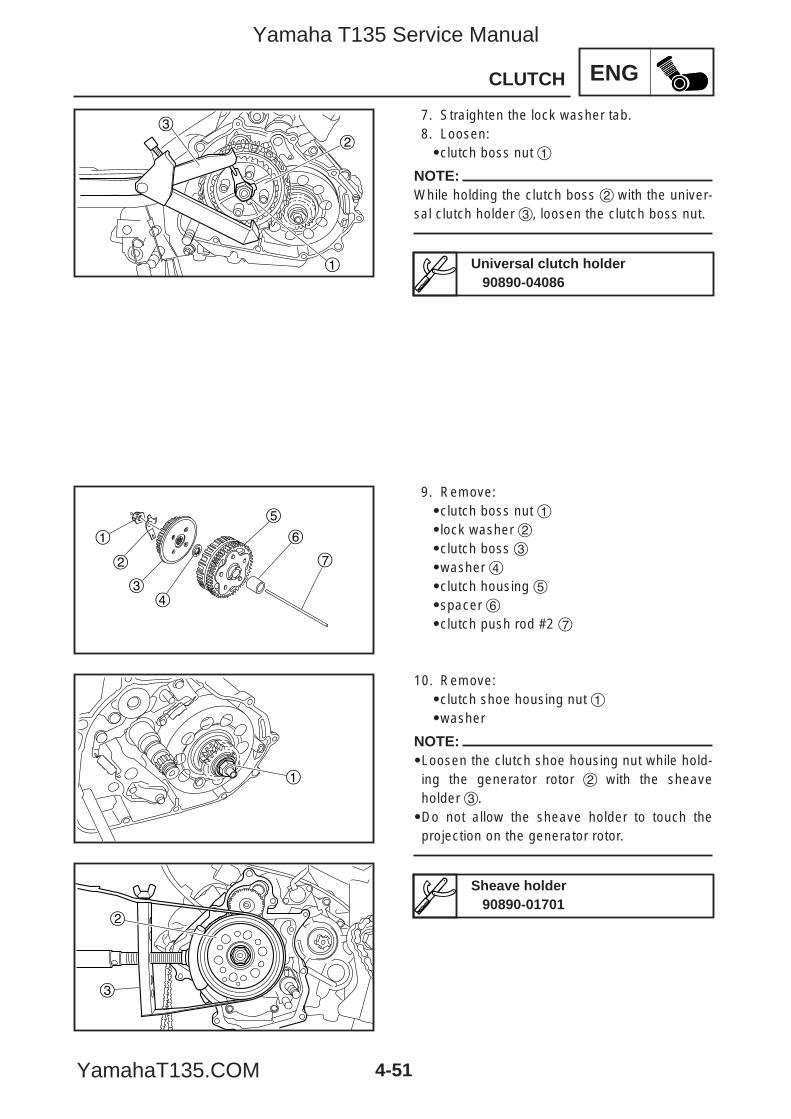
ENG
2
1
3
1
2
34
5
6
7
1
3
2
4-51
CLUTCH
7. Straighten the lock washer tab.8. Loosen:9clutch boss nut 1
NOTE:While holding the clutch boss 2 with the univer-sal clutch holder 3, loosen the clutch boss nut.
9. Remove:9clutch boss nut 19lock washer 29clutch boss 39washer 49clutch housing 59spacer 69clutch push rod #2 7
10. Remove:9clutch shoe housing nut 19washer
NOTE:9Loosen the clutch shoe housing nut while hold-ing the generator rotor 2 with the sheaveholder 3.9Do not allow the sheave holder to touch theprojection on the generator rotor.
Universal clutch holder90890-04086
Sheave holder90890-01701
5YP-F8197-E0_4_1 05.6.27 19:32 Page 51
Yamaha T135 Service Manual
YamahaT135.COM
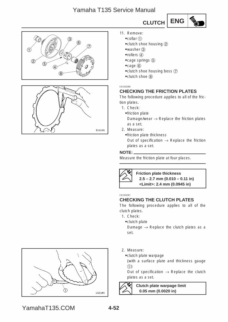
ENG
1
25
4
36
7
8
4-52
CLUTCH
11. Remove:9collar 19clutch shoe housing 29washer 39rollers 49cage springs 59cage 69clutch shoe housing boss 79clutch shoe 8
EAS00280
CHECKING THE FRICTION PLATESThe following procedure applies to all of the fric-tion plates.1. Check:9friction plateDamage/wear → Replace the friction platesas a set.
2. Measure:9friction plate thicknessOut of specification → Replace the frictionplates as a set.
NOTE:Measure the friction plate at four places.
EAS00281
CHECKING THE CLUTCH PLATESThe following procedure applies to all of theclutch plates.1. Check:9clutch plateDamage → Replace the clutch plates as aset.
2. Measure:9clutch plate warpage(with a surface plate and thickness gauge1)Out of specification → Replace the clutchplates as a set.
Friction plate thickness2.5 – 2.7 mm (0.010 – 0.11 in)<Limit>: 2.4 mm (0.0945 in)
Clutch plate warpage limit0.05 mm (0.0020 in)
5YP-F8197-E0_4_1 05.6.27 19:32 Page 52
Yamaha T135 Service Manual
YamahaT135.COM
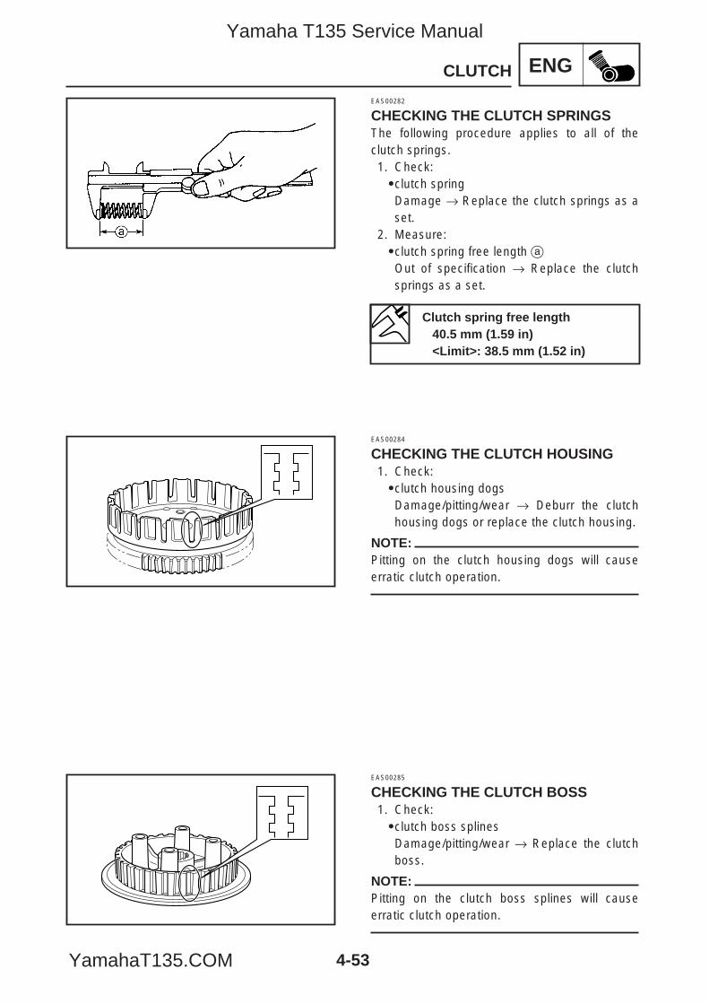
ENG
4-53
CLUTCH
EAS00282
CHECKING THE CLUTCH SPRINGSThe following procedure applies to all of theclutch springs.1. Check:9clutch springDamage → Replace the clutch springs as aset.
2. Measure:9clutch spring free length aOut of specification → Replace the clutchsprings as a set.
EAS00284
CHECKING THE CLUTCH HOUSING1. Check:9clutch housing dogsDamage/pitting/wear → Deburr the clutchhousing dogs or replace the clutch housing.
NOTE:Pitting on the clutch housing dogs will causeerratic clutch operation.
EAS00285
CHECKING THE CLUTCH BOSS1. Check:9clutch boss splinesDamage/pitting/wear → Replace the clutchboss.
NOTE:Pitting on the clutch boss splines will causeerratic clutch operation.
Clutch spring free length40.5 mm (1.59 in)<Limit>: 38.5 mm (1.52 in)
5YP-F8197-E0_4_1 05.6.27 19:32 Page 53
Yamaha T135 Service Manual
YamahaT135.COM
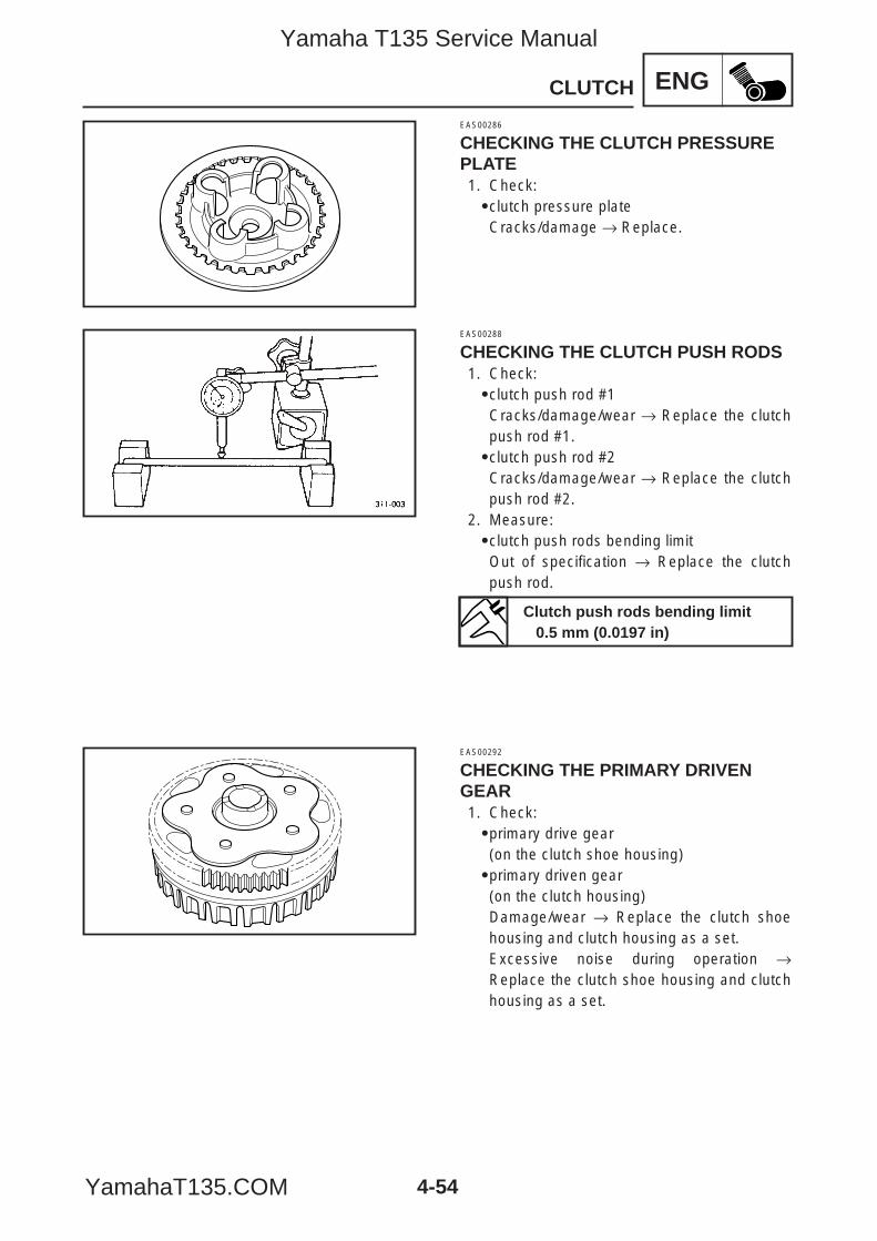
ENG
4-54
CLUTCH
EAS00286
CHECKING THE CLUTCH PRESSUREPLATE1. Check:9clutch pressure plateCracks/damage → Replace.
EAS00288
CHECKING THE CLUTCH PUSH RODS1. Check:9clutch push rod #1Cracks/damage/wear → Replace the clutchpush rod #1.9clutch push rod #2Cracks/damage/wear → Replace the clutchpush rod #2.
2. Measure:9clutch push rods bending limitOut of specification → Replace the clutchpush rod.
EAS00292
CHECKING THE PRIMARY DRIVENGEAR1. Check:9primary drive gear(on the clutch shoe housing)9primary driven gear(on the clutch housing)Damage/wear → Replace the clutch shoehousing and clutch housing as a set.Excessive noise during operation →Replace the clutch shoe housing and clutchhousing as a set.
Clutch push rods bending limit0.5 mm (0.0197 in)
5YP-F8197-E0_4_1 05.6.27 19:32 Page 54
Yamaha T135 Service Manual
YamahaT135.COM
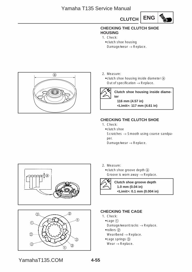
ENG
a
1
2
12
4-55
CLUTCH
CHECKING THE CLUTCH SHOEHOUSING1. Check:9clutch shoe housingDamage/wear → Replace.
2. Measure:9clutch shoe housing inside diameter aOut of specification → Replace.
CHECKING THE CLUTCH SHOE1. Check:9clutch shoeScratches → Smooth using coarse sandpa-per.Damage/wear → Replace.
2. Measure:9clutch shoe groove depth aGroove is worn away → Replace.
CHECKING THE CAGE1. Check:9cage 1Damage/wear/cracks → Replace.9rollers 2Wear/bend → Replace.9cage springs 3Wear → Replace.
Clutch shoe housing inside diame-ter
116 mm (4.57 in)<Limit>: 117 mm (4.61 in)
Clutch shoe groove depth1.0 mm (0.04 in)<Limit>: 0.1 mm (0.004 in)
5YP-F8197-E0_4_1 05.6.27 19:32 Page 55
Yamaha T135 Service Manual
YamahaT135.COM
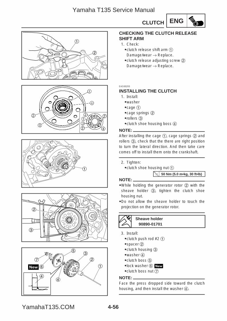
ENG
4-56
CLUTCH
1
2
1
3
2
7
6
5
4
3
2
1
4
CHECKING THE CLUTCH RELEASESHIFT ARM1. Check:9clutch release shift arm 1Damage/wear → Replace.9clutch release adjusting screw 2Damage/wear → Replace.
EAS00293
INSTALLING THE CLUTCH1. Install:9washer9cage 19cage springs 29rollers 39clutch shoe housing boss 4
NOTE:After installing the cage 1, cage springs 2 androllers 3, check that the there are right positionto turn the lateral direction. And then take carecomes off to install them onto the crankshaft.
2. Tighten:9clutch shoe housing nut 1
NOTE:9While holding the generator rotor 2 with thesheave holder 3, tighten the clutch shoehousing nut.9Do not allow the sheave holder to touch theprojection on the generator rotor.
3. Install:9clutch push rod #2 19spacer 29clutch housing 39washer 49clutch boss 59lock washer 69clutch boss nut 7
NOTE:Face the press dropped side toward the clutchhousing, and then install the washer 4.
Sheave holder90890-01701
50 Nm (5.0 m•kg, 30 ft•lb)
5YP-F8197-E0_4_1 05.6.27 19:32 Page 56
Yamaha T135 Service Manual
YamahaT135.COM
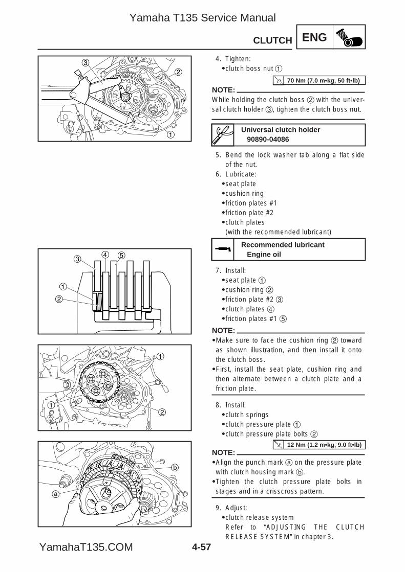
ENG
4-57
CLUTCH
2
1
3
1
2
34 5
1
1
2
a
b
4. Tighten:9clutch boss nut 1
NOTE:While holding the clutch boss 2 with the univer-sal clutch holder 3, tighten the clutch boss nut.
5. Bend the lock washer tab along a flat sideof the nut.
6. Lubricate:9seat plate9cushion ring9friction plates #19friction plate #29clutch plates(with the recommended lubricant)
7. Install:9seat plate 19cushion ring 29friction plate #2 39clutch plates 49friction plates #1 5
NOTE:9Make sure to face the cushion ring 2 towardas shown illustration, and then install it ontothe clutch boss.9First, install the seat plate, cushion ring andthen alternate between a clutch plate and afriction plate.
8. Install:9clutch springs9clutch pressure plate 19clutch pressure plate bolts 2
NOTE:9Align the punch mark a on the pressure platewith clutch housing mark b.9Tighten the clutch pressure plate bolts instages and in a crisscross pattern.
9. Adjust:9clutch release systemRefer to “ADJUSTING THE CLUTCHRELEASE SYSTEM” in chapter 3.
Universal clutch holder90890-04086
Recommended lubricantEngine oil
70 Nm (7.0 m•kg, 50 ft•lb)
12 Nm (1.2 m•kg, 9.0 ft•lb)
5YP-F8197-E0_4_1 05.6.27 19:33 Page 57
Yamaha T135 Service Manual
YamahaT135.COM
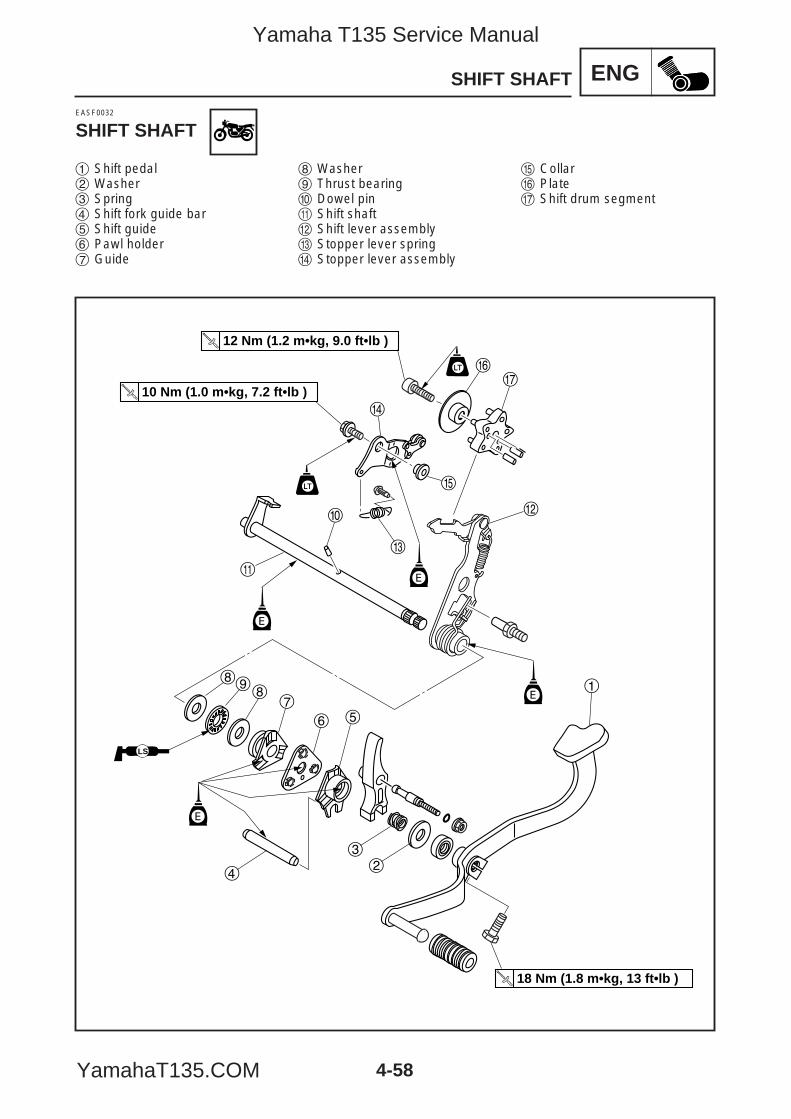
4-58
ENG
w
r
yu
t
e
0
q
898
7
6 5
32
4
1
12 Nm (1.2 m•kg, 9.0 ft•lb )
10 Nm (1.0 m•kg, 7.2 ft•lb )
18 Nm (1.8 m•kg, 13 ft•lb )
E
E
E
E
LS
SHIFT SHAFT
EASF0032
SHIFT SHAFT
1 Shift pedal2 Washer3 Spring4 Shift fork guide bar5 Shift guide6 Pawl holder7 Guide
8 Washer9 Thrust bearing0 Dowel pinq Shift shaftw Shift lever assemblye Stopper lever springr Stopper lever assembly
t Collary Plateu Shift drum segment
5YP-F8197-E0_4_1 05.6.27 19:33 Page 58
Yamaha T135 Service Manual
YamahaT135.COM
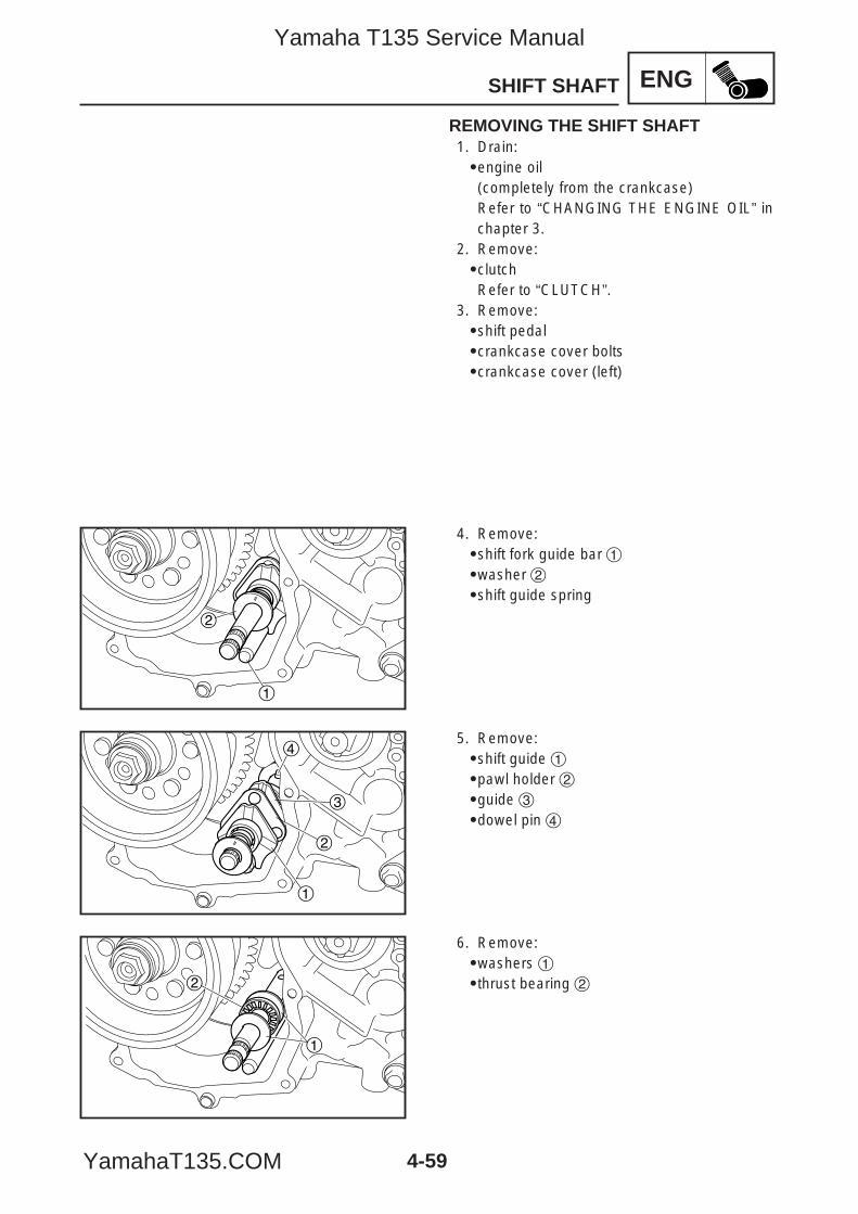
ENG
4-59
SHIFT SHAFT
1
2
2
1
3
4
2
1
REMOVING THE SHIFT SHAFT1. Drain:9engine oil(completely from the crankcase)Refer to “CHANGING THE ENGINE OIL” inchapter 3.
2. Remove:9clutchRefer to “CLUTCH”.
3. Remove:9shift pedal9crankcase cover bolts9crankcase cover (left)
4. Remove:9shift fork guide bar 19washer 29shift guide spring
5. Remove:9shift guide 19pawl holder 29guide 39dowel pin 4
6. Remove:9washers 19thrust bearing 2
5YP-F8197-E0_4_1 05.6.27 19:33 Page 59
Yamaha T135 Service Manual
YamahaT135.COM
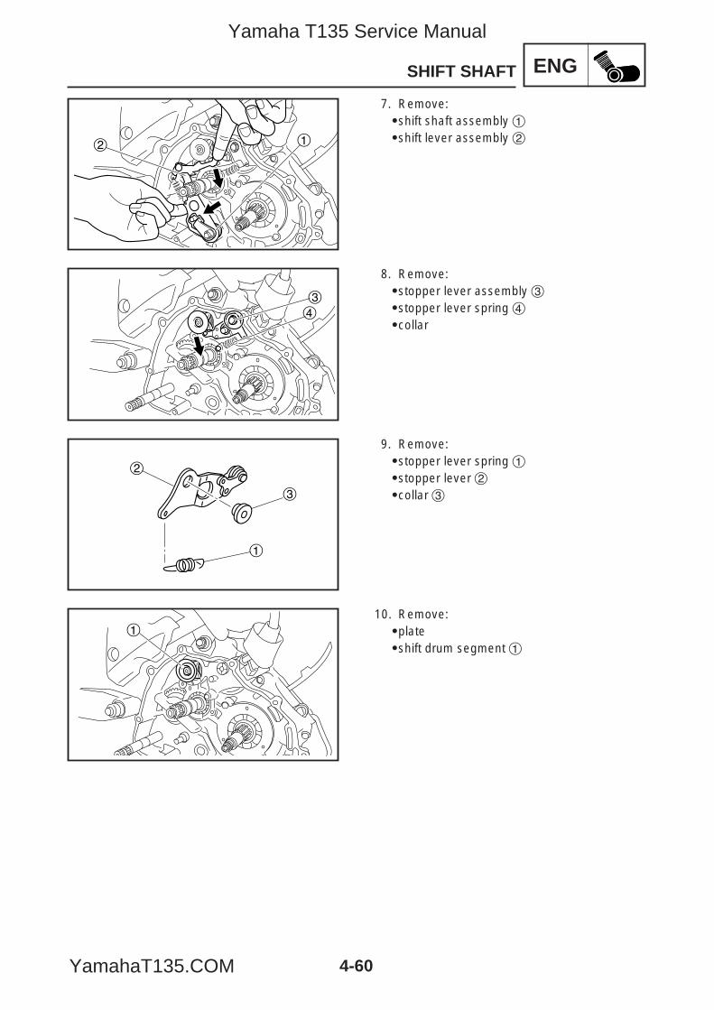
ENG
4-60
SHIFT SHAFT
2 1
34
1
2
3
1
7. Remove:9shift shaft assembly 19shift lever assembly 2
8. Remove:9stopper lever assembly 39stopper lever spring 49collar
9. Remove:9stopper lever spring 19stopper lever 29collar 3
10. Remove:9plate9shift drum segment 1
5YP-F8197-E0_4_1 05.6.27 19:33 Page 60
Yamaha T135 Service Manual
YamahaT135.COM
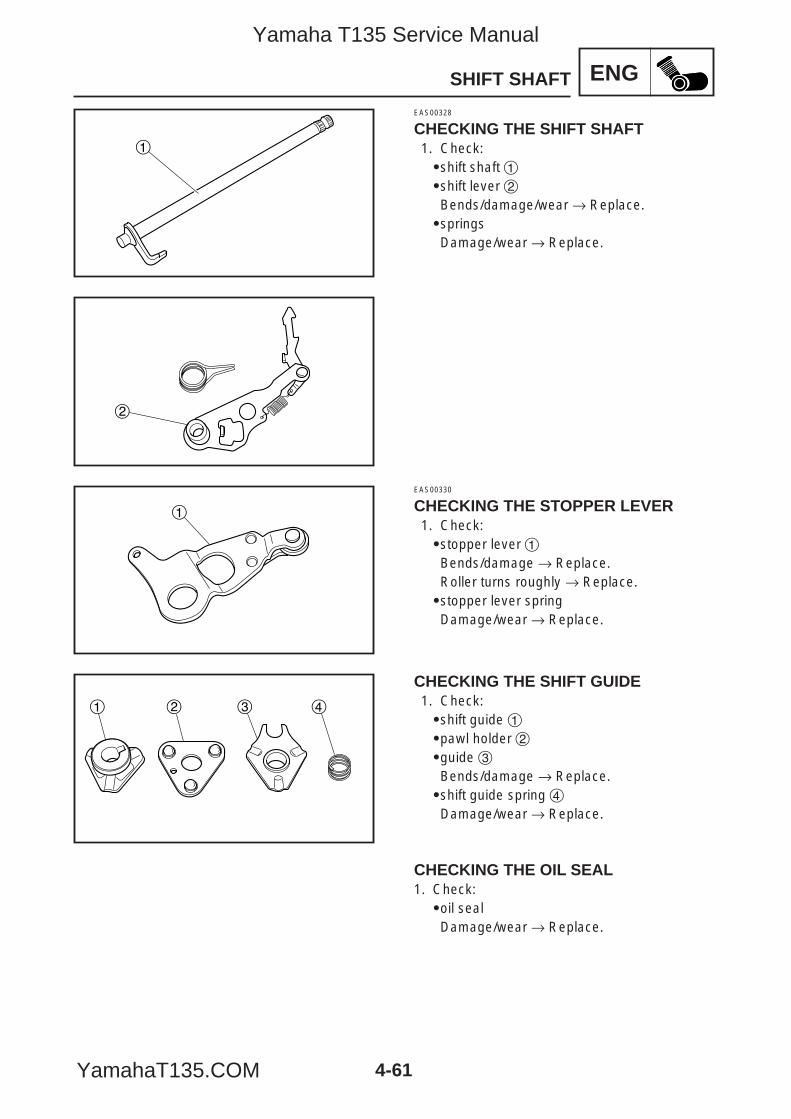
ENG
1
2
1
1 2 3 4
4-61
SHIFT SHAFT
EAS00328
CHECKING THE SHIFT SHAFT1. Check:9shift shaft 19shift lever 2Bends/damage/wear → Replace.9springsDamage/wear → Replace.
EAS00330
CHECKING THE STOPPER LEVER1. Check:9stopper lever 1Bends/damage → Replace.Roller turns roughly → Replace.9stopper lever springDamage/wear → Replace.
CHECKING THE SHIFT GUIDE1. Check:9shift guide 19pawl holder 29guide 3Bends/damage → Replace.9shift guide spring 4Damage/wear → Replace.
CHECKING THE OIL SEAL1. Check:9oil sealDamage/wear → Replace.
5YP-F8197-E0_4_1 05.6.27 19:33 Page 61
Yamaha T135 Service Manual
YamahaT135.COM
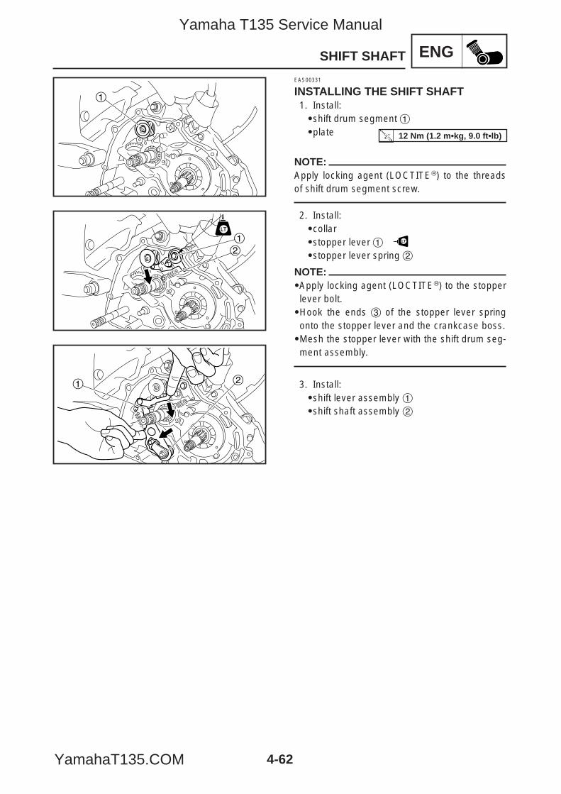
ENG
4-62
SHIFT SHAFT
1
12
1 2
EAS00331
INSTALLING THE SHIFT SHAFT1. Install:9shift drum segment 19plate
NOTE:Apply locking agent (LOCTITER) to the threadsof shift drum segment screw.
2. Install:9collar9stopper lever 1
9stopper lever spring 2
NOTE:9Apply locking agent (LOCTITER) to the stopperlever bolt.9Hook the ends 3 of the stopper lever springonto the stopper lever and the crankcase boss.9Mesh the stopper lever with the shift drum seg-ment assembly.
3. Install:9shift lever assembly 19shift shaft assembly 2
LT
12 Nm (1.2 m•kg, 9.0 ft•lb)
5YP-F8197-E0_4_1 05.6.27 19:33 Page 62
Yamaha T135 Service Manual
YamahaT135.COM
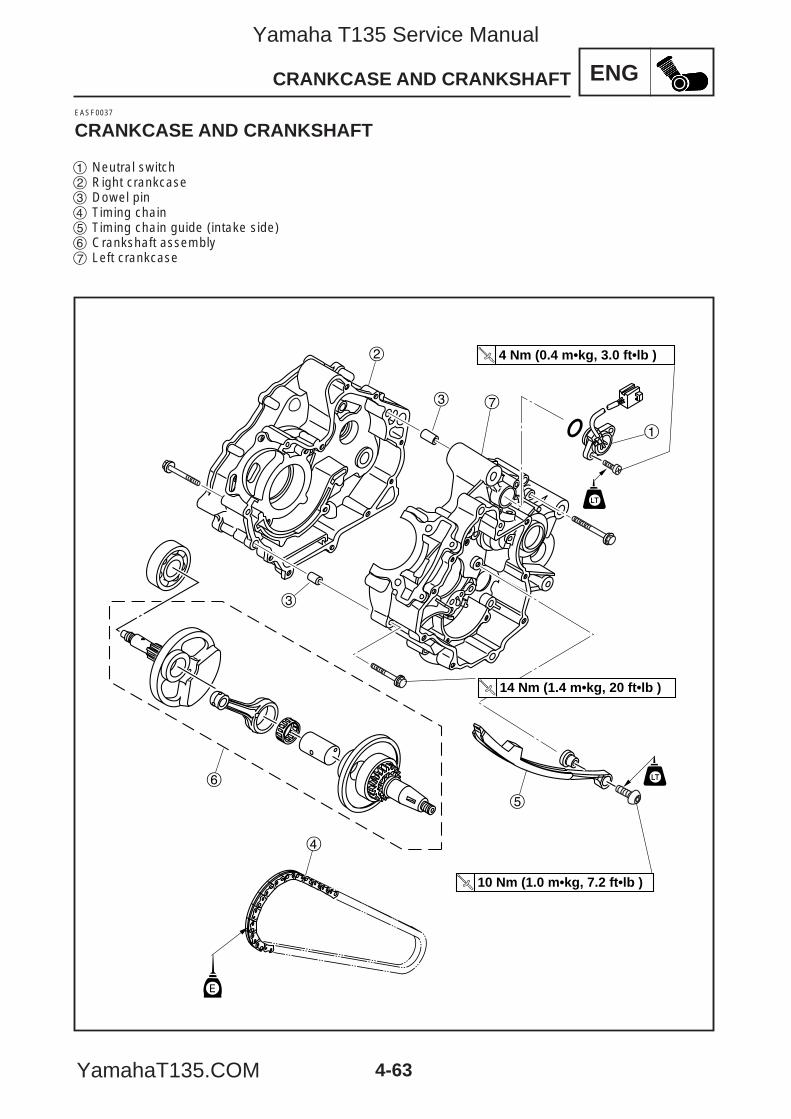
ENG
2
3 7
1
3
6
4
5
14 Nm (1.4 m•kg, 20 ft•lb )
10 Nm (1.0 m•kg, 7.2 ft•lb )
E
4 Nm (0.4 m•kg, 3.0 ft•lb )
4-63
CRANKCASE AND CRANKSHAFT
EASF0037
CRANKCASE AND CRANKSHAFT
1 Neutral switch2 Right crankcase3 Dowel pin4 Timing chain5 Timing chain guide (intake side)6 Crankshaft assembly7 Left crankcase
5YP-F8197-E0_4_1 05.6.27 19:33 Page 63
Yamaha T135 Service Manual
YamahaT135.COM
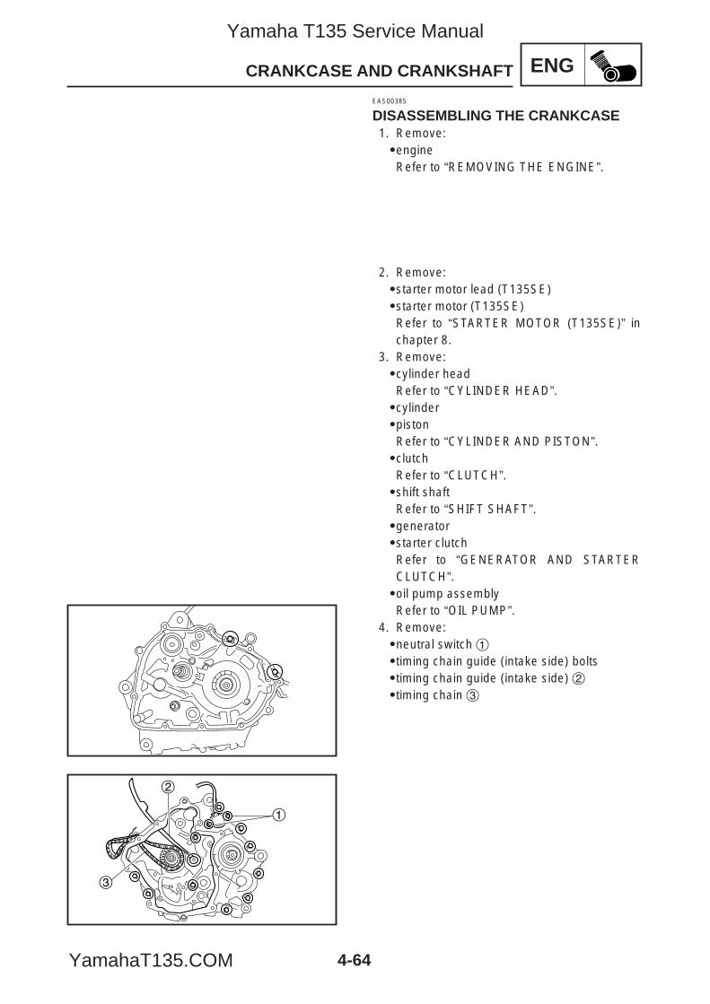
ENG
4-64
CRANKCASE AND CRANKSHAFT
1
2
3
EAS00385
DISASSEMBLING THE CRANKCASE1. Remove:9engineRefer to “REMOVING THE ENGINE”.
2. Remove:9starter motor lead (T135SE)9starter motor (T135SE)Refer to “STARTER MOTOR (T135SE)” inchapter 8.
3. Remove:9cylinder headRefer to “CYLINDER HEAD”.9cylinder9pistonRefer to “CYLINDER AND PISTON”.9clutchRefer to “CLUTCH”.9shift shaftRefer to “SHIFT SHAFT”.9generator9starter clutchRefer to “GENERATOR AND STARTERCLUTCH”.9oil pump assemblyRefer to “OIL PUMP”.
4. Remove:9neutral switch 19timing chain guide (intake side) bolts 9timing chain guide (intake side) 29timing chain 3
5YP-F8197-E0_4_1 05.6.27 19:33 Page 64
Yamaha T135 Service Manual
YamahaT135.COM
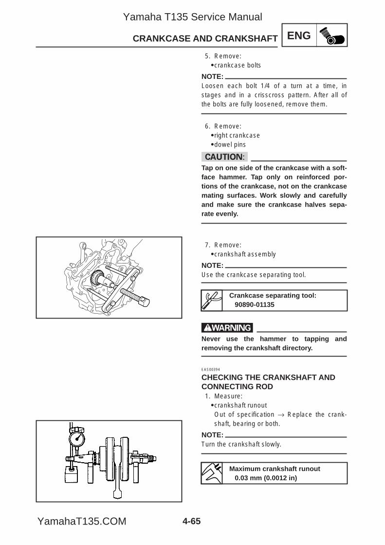
ENG
4-65
CRANKCASE AND CRANKSHAFT
5. Remove:9crankcase bolts
NOTE:Loosen each bolt 1/4 of a turn at a time, instages and in a crisscross pattern. After all ofthe bolts are fully loosened, remove them.
6. Remove:9right crankcase9dowel pins
cCTap on one side of the crankcase with a soft-face hammer. Tap only on reinforced por-tions of the crankcase, not on the crankcasemating surfaces. Work slowly and carefullyand make sure the crankcase halves sepa-rate evenly.
7. Remove:9crankshaft assembly
NOTE:Use the crankcase separating tool.
wNever use the hammer to tapping andremoving the crankshaft directory.
EAS00394
CHECKING THE CRANKSHAFT ANDCONNECTING ROD1. Measure:9crankshaft runoutOut of specification → Replace the crank-shaft, bearing or both.
NOTE:Turn the crankshaft slowly.
Maximum crankshaft runout0.03 mm (0.0012 in)
Crankcase separating tool:90890-01135
5YP-F8197-E0_4_1 05.6.27 19:33 Page 65
Yamaha T135 Service Manual
YamahaT135.COM
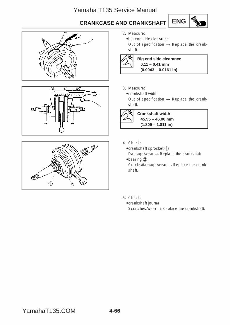
ENG
4-66
CRANKCASE AND CRANKSHAFT
2. Measure:9big end side clearanceOut of specification → Replace the crank-shaft.
3. Measure:9crankshaft widthOut of specification → Replace the crank-shaft.
4. Check:9crankshaft sprocket 1Damage/wear → Replace the crankshaft.9bearing 2Cracks/damage/wear → Replace the crank-shaft.
5. Check:9crankshaft journalScratches/wear → Replace the crankshaft.
Big end side clearance0.11 – 0.41 mm(0.0043 – 0.0161 in)
Crankshaft width45.95 – 46.00 mm(1.809 – 1.811 in)
5YP-F8197-E0_4_1 05.6.27 19:33 Page 66
Yamaha T135 Service Manual
YamahaT135.COM
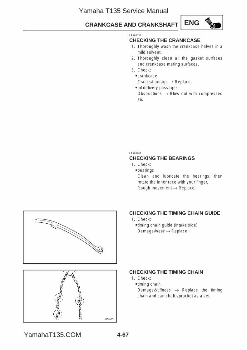
ENG
4-67
CRANKCASE AND CRANKSHAFT
EAS00399
CHECKING THE CRANKCASE1. Thoroughly wash the crankcase halves in a
mild solvent.2. Thoroughly clean all the gasket surfaces
and crankcase mating surfaces.3. Check:9crankcaseCracks/damage → Replace.9oil delivery passagesObstructions → Blow out with compressedair.
EAS00401
CHECKING THE BEARINGS1. Check:9bearingsClean and lubricate the bearings, thenrotate the inner race with your finger.Rough movement → Replace.
CHECKING THE TIMING CHAIN GUIDE1. Check:9timing chain guide (intake side)Damage/wear → Replace.
CHECKING THE TIMING CHAIN1. Check:9timing chainDamage/stiffness → Replace the timingchain and camshaft sprocket as a set.
5YP-F8197-E0_4_1 05.6.27 19:33 Page 67
Yamaha T135 Service Manual
YamahaT135.COM
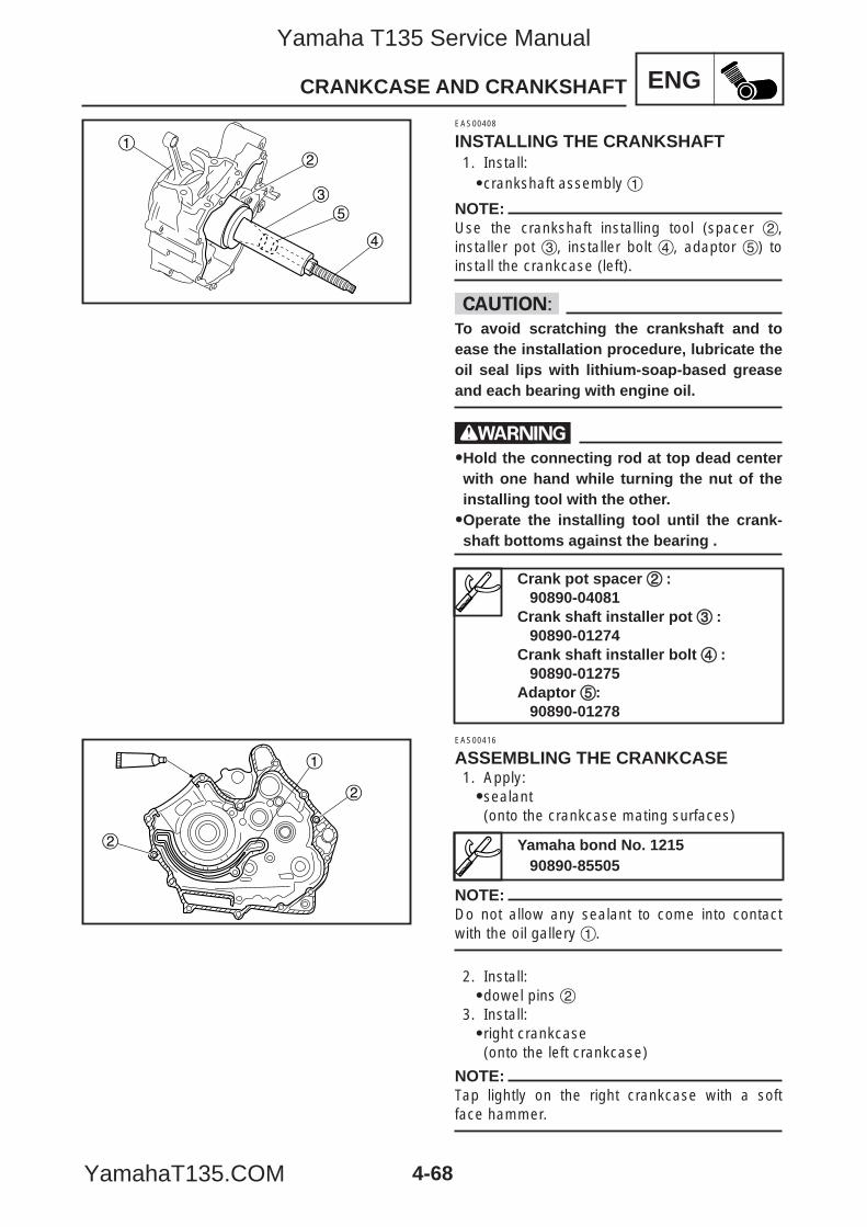
ENG
12
3
4
5
2
2
1
4-68
CRANKCASE AND CRANKSHAFT
EAS00408
INSTALLING THE CRANKSHAFT1. Install:9crankshaft assembly 1
NOTE:Use the crankshaft installing tool (spacer 2,installer pot 3, installer bolt 4, adaptor 5) toinstall the crankcase (left).
cCTo avoid scratching the crankshaft and toease the installation procedure, lubricate theoil seal lips with lithium-soap-based greaseand each bearing with engine oil.
w99Hold the connecting rod at top dead centerwith one hand while turning the nut of theinstalling tool with the other.99Operate the installing tool until the crank-shaft bottoms against the bearing .
EAS00416
ASSEMBLING THE CRANKCASE1. Apply:99sealant(onto the crankcase mating surfaces)
NOTE:Do not allow any sealant to come into contactwith the oil gallery 1.
2. Install:9dowel pins 2
3. Install:9right crankcase(onto the left crankcase)
NOTE:Tap lightly on the right crankcase with a softface hammer.
Yamaha bond No. 121590890-85505
Crank pot spacer 22 :90890-04081
Crank shaft installer pot 33 :90890-01274
Crank shaft installer bolt 44 :90890-01275
Adaptor 55:90890-01278
5YP-F8197-E0_4_1 05.6.27 19:33 Page 68
Yamaha T135 Service Manual
YamahaT135.COM
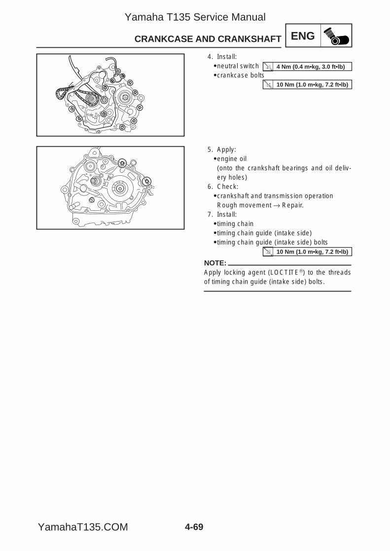
ENG
4-69
CRANKCASE AND CRANKSHAFT
4. Install:9neutral switch9crankcase bolts
5. Apply:9engine oil(onto the crankshaft bearings and oil deliv-ery holes)
6. Check:9crankshaft and transmission operationRough movement → Repair.
7. Install:9timing chain9timing chain guide (intake side)9timing chain guide (intake side) bolts
NOTE:Apply locking agent (LOCTITER) to the threadsof timing chain guide (intake side) bolts.
10 Nm (1.0 m•kg, 7.2 ft•lb)
4 Nm (0.4 m•kg, 3.0 ft•lb)
10 Nm (1.0 m•kg, 7.2 ft•lb)
5YP-F8197-E0_4_1 05.6.27 19:33 Page 69
Yamaha T135 Service Manual
YamahaT135.COM
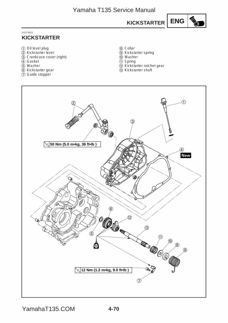
ENG
1
3
2
4
w
5
6
e
q
8
9
0
7
12 Nm (1.2 m•kg, 9.0 ft•lb )
M
50 Nm (5.0 m•kg, 36 ft•lb )
4-70
1 Oil level plug2 Kickstarter lever3 Crankcase cover (right)4 Gasket5 Washer6 Kickstarter gear7 Guide stopper
8 Collar9 Kickstarter spring0 Washerq Springw Kickstarter ratchet geare Kickstarter shaft
ENGKICKSTARTER
EASF0033
KICKSTARTER
5YP-F8197-E0_4_1 05.6.27 19:33 Page 70
Yamaha T135 Service Manual
YamahaT135.COM
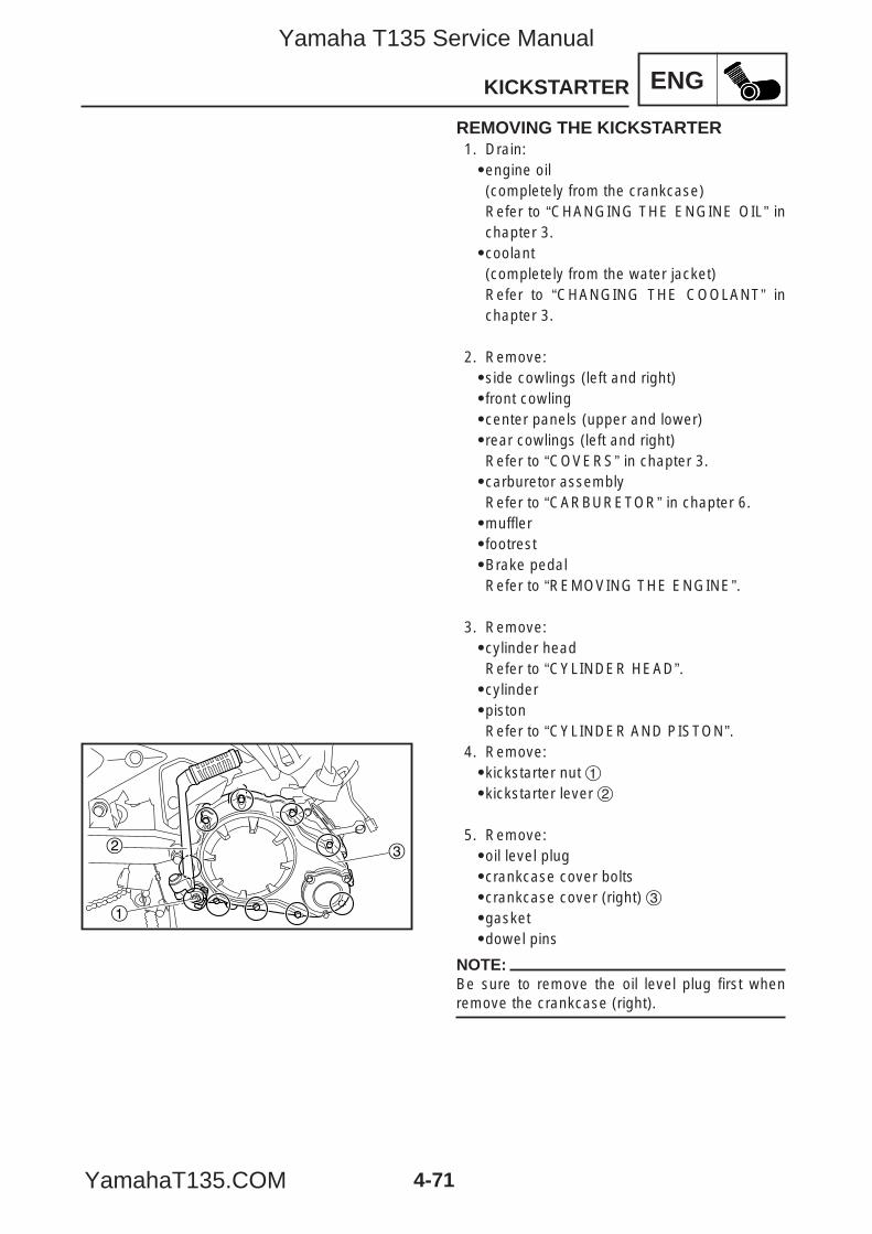
ENG
4-71
1
2 3
KICKSTARTER
REMOVING THE KICKSTARTER1. Drain:9engine oil(completely from the crankcase)Refer to “CHANGING THE ENGINE OIL” inchapter 3.9coolant(completely from the water jacket)Refer to “CHANGING THE COOLANT” inchapter 3.
2. Remove:9side cowlings (left and right)9front cowling9center panels (upper and lower)9rear cowlings (left and right)Refer to “COVERS” in chapter 3.9carburetor assemblyRefer to “CARBURETOR” in chapter 6.9muffler9footrest9Brake pedalRefer to “REMOVING THE ENGINE”.
3. Remove:9cylinder headRefer to “CYLINDER HEAD”.9cylinder9pistonRefer to “CYLINDER AND PISTON”.
4. Remove:9kickstarter nut 19kickstarter lever 2
5. Remove:9oil level plug9crankcase cover bolts9crankcase cover (right) 39gasket9dowel pins
NOTE:Be sure to remove the oil level plug first whenremove the crankcase (right).
5YP-F8197-E0_4_1 05.6.27 19:33 Page 71
Yamaha T135 Service Manual
YamahaT135.COM
ENGKICKSTARTER
4-72
6. Remove:9clutchRefer to “CLUTCH”.9shift shaftRefer to “SHIFT SHAFT”.9oil pump assemblyRefer to “SOIL PUMP”.9generator9starter clutchRefer to “GENERATOR AND STARTERCLUTCH.
7. Remove:9starter motor (T135SE)Refer to “STARTER MOTOR” in chapter 8.
8. Remove:9engineRefer to “REMOVING THE ENGINE”.
9. Separate:9crankcaseRefer to “CRANKCASE”.
10. Remove:9guide stopper9kickstarter shaft assembly
5YP-F8197-E0_4_1 05.6.27 19:33 Page 72
Yamaha T135 Service Manual
YamahaT135.COM
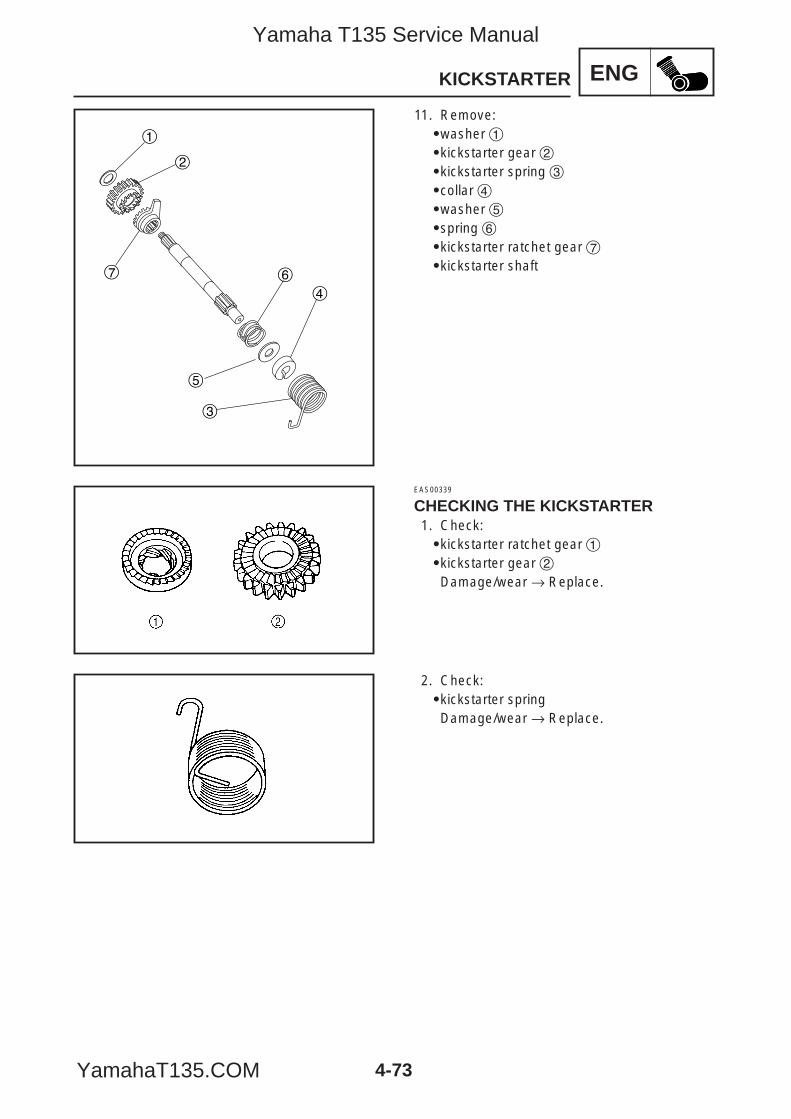
ENG
4-73
KICKSTARTER
1
2
3
4
5
67
11. Remove:9washer 19kickstarter gear 29kickstarter spring 39collar 49washer 59spring 69kickstarter ratchet gear 79kickstarter shaft
EAS00339
CHECKING THE KICKSTARTER1. Check:9kickstarter ratchet gear 19kickstarter gear 2Damage/wear → Replace.
2. Check:9kickstarter springDamage/wear → Replace.
5YP-F8197-E0_4_1 05.6.27 19:33 Page 73
Yamaha T135 Service Manual
YamahaT135.COM
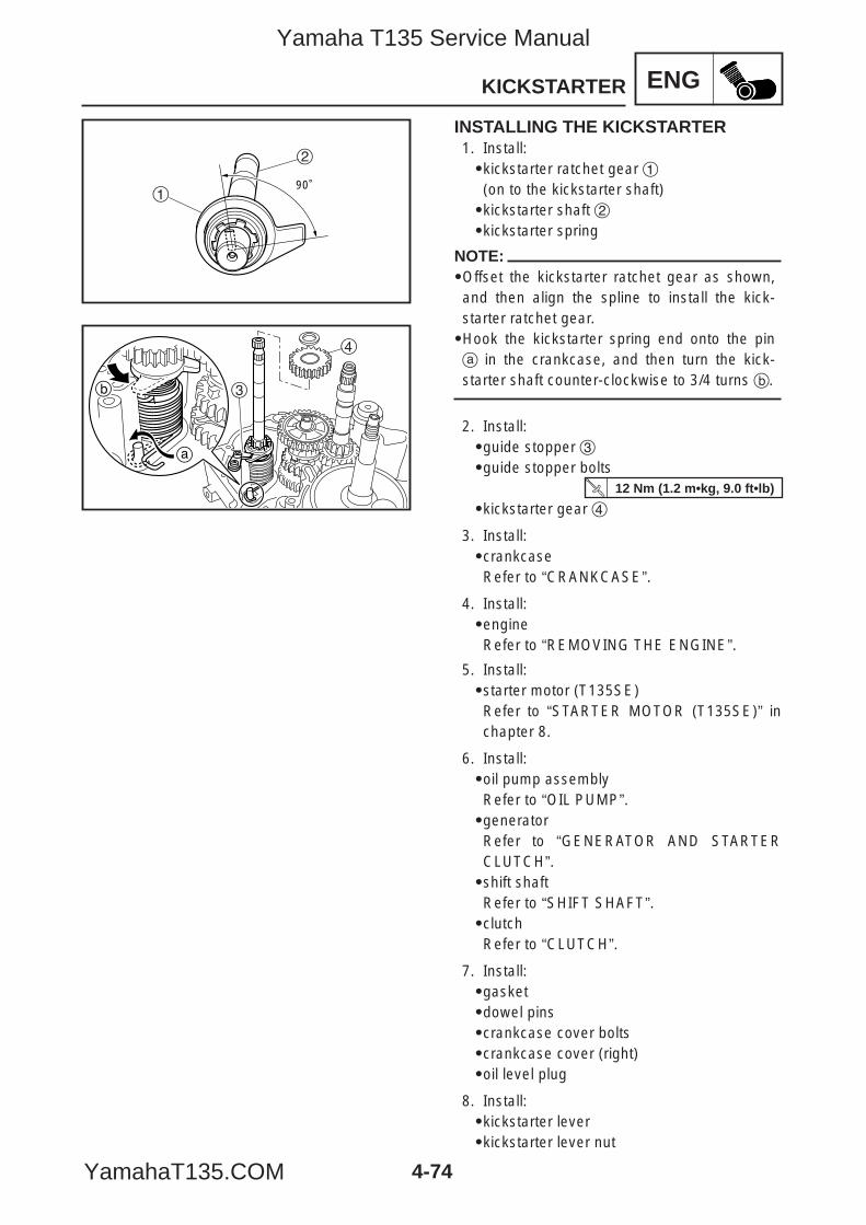
ENG
4-74
90˚1
2
a
b
4
3
KICKSTARTER
INSTALLING THE KICKSTARTER1. Install:9kickstarter ratchet gear 1(on to the kickstarter shaft)9kickstarter shaft 29kickstarter spring
NOTE:9Offset the kickstarter ratchet gear as shown,and then align the spline to install the kick-starter ratchet gear.9Hook the kickstarter spring end onto the pina in the crankcase, and then turn the kick-starter shaft counter-clockwise to 3/4 turns b.
2. Install:9guide stopper 39guide stopper bolts
9kickstarter gear 4
3. Install:9crankcaseRefer to “CRANKCASE”.
4. Install:9engine Refer to “REMOVING THE ENGINE”.
5. Install:9starter motor (T135SE)Refer to “STARTER MOTOR (T135SE)” inchapter 8.
6. Install:9oil pump assemblyRefer to “OIL PUMP”.9generatorRefer to “GENERATOR AND STARTERCLUTCH”.9shift shaftRefer to “SHIFT SHAFT”.9clutchRefer to “CLUTCH”.
7. Install:9gasket9dowel pins9crankcase cover bolts9crankcase cover (right)9oil level plug
8. Install:9kickstarter lever9kickstarter lever nut
12 Nm (1.2 m•kg, 9.0 ft•lb)
5YP-F8197-E0_4_1 05.6.27 19:33 Page 74
Yamaha T135 Service Manual
YamahaT135.COM
ENGKICKSTARTER
4-75
9. Install:9piston9cylinderRefer to “CYLINDER AND PISTON”.9cylinder headRefer to “CYLINDER HEAD”.9radiator assemblyRefer to “RADIATOR” in chapter 5.9cylinder headRefer to “CYLINDER HEAD”.
10. Install:9muffler9footrest9brake pedalRefer to “REMOVING THE ENGINE”.9inner panel9center panels (left and right)9front cowling9side cowlings (left and right)Refer to “COVERS” in chapter 3.
11. Fill:9coolant(completely from the water jacket)Refer to “CHANGING THE COOLANT” inchapter 3.9engine oil(completely from the crankcase)Refer to “CHANGING THE ENGINE OIL” inchapter 3.
5YP-F8197-E0_4_1 05.6.27 19:33 Page 75
Yamaha T135 Service Manual
YamahaT135.COM
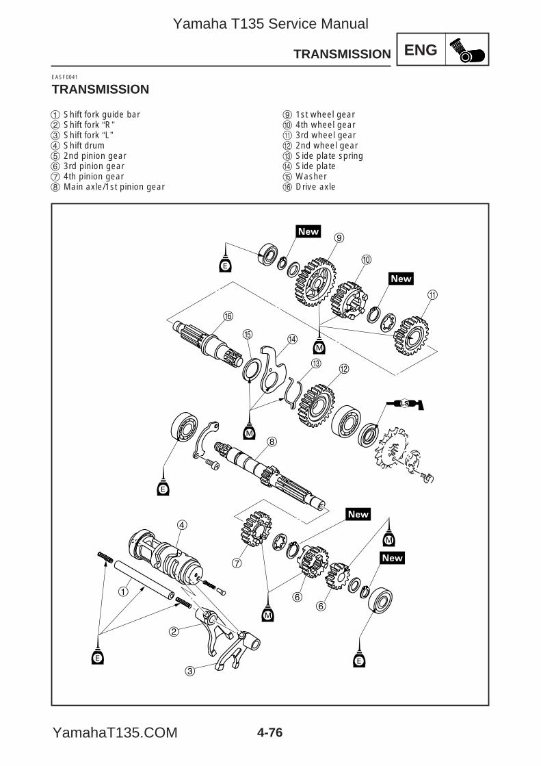
ENG
4-76
TRANSMISSION
9
0
q
y
rt
ew
8
7
66
4
1
2
3
M
M
M
M
E
E
EE
EASF0041
TRANSMISSION
1 Shift fork guide bar2 Shift fork “R”3 Shift fork “L”4 Shift drum5 2nd pinion gear6 3rd pinion gear7 4th pinion gear8 Main axle/1st pinion gear
9 1st wheel gear0 4th wheel gearq 3rd wheel gearw 2nd wheel geare Side plate springr Side platet Washery Drive axle
5YP-F8197-E0_4_1 05.6.27 19:33 Page 76
Yamaha T135 Service Manual
YamahaT135.COM
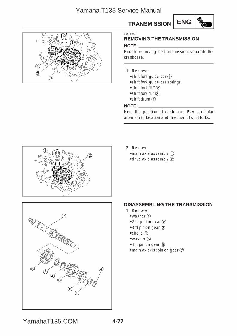
ENG
4-77
TRANSMISSION
4
23
1
12
12
34
45
6
7
EASF0042
REMOVING THE TRANSMISSIONNOTE:Prior to removing the transmission, separate thecrankcase.
1. Remove:9shift fork guide bar 19shift fork guide bar springs9shift fork “R” 29shift fork “L” 39shift drum 4
NOTE:Note the position of each part. Pay particularattention to location and direction of shift forks.
2. Remove:9main axle assembly 19drive axle assembly 2
DISASSEMBLING THE TRANSMISSION1. Remove:9washer 192nd pinion gear 293rd pinion gear 39circlip 49washer 594th pinion gear 69main axle/1st pinion gear 7
5YP-F8197-E0_4_1 05.6.27 19:33 Page 77
Yamaha T135 Service Manual
YamahaT135.COM
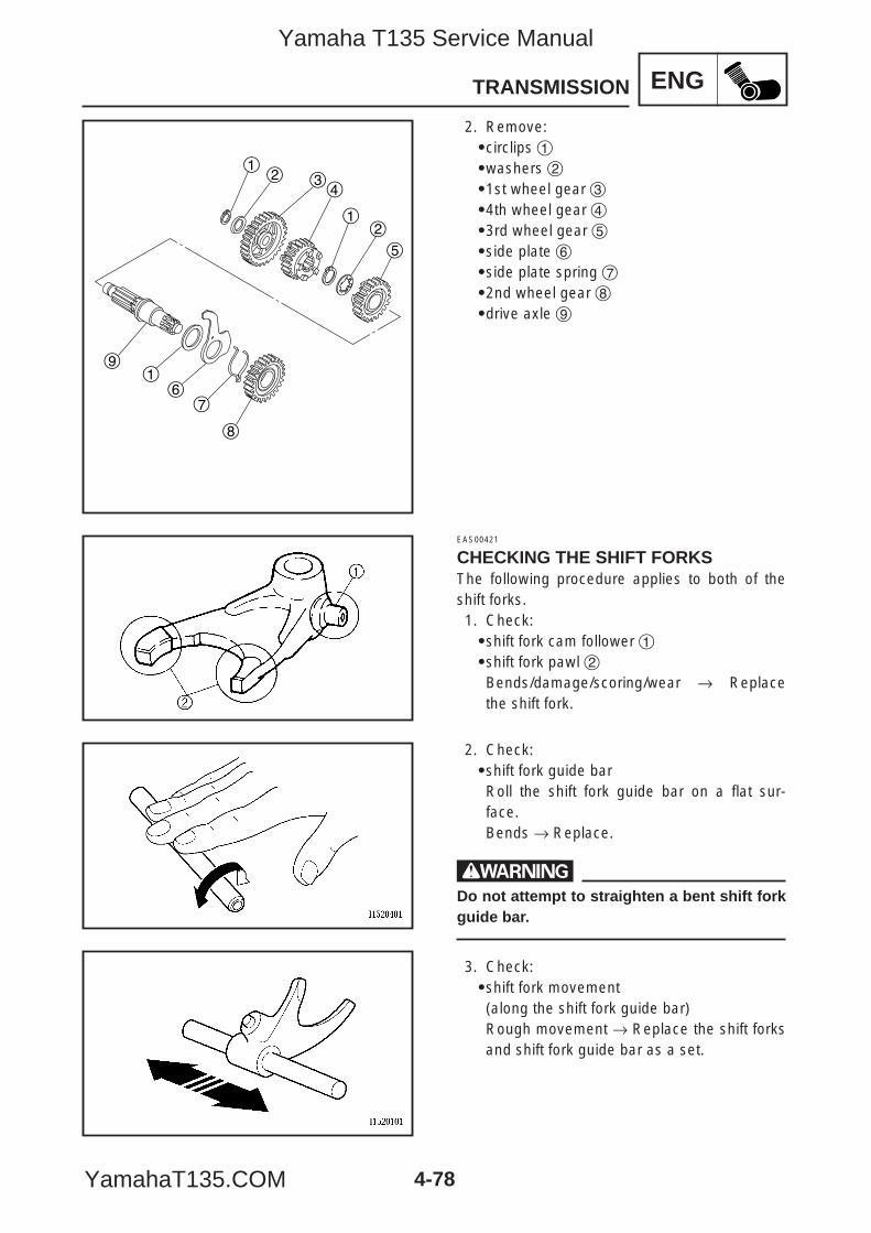
ENG
4-78
TRANSMISSION
12
12
1
34
5
67
8
9
2. Remove:9circlips 19washers 291st wheel gear 394th wheel gear 493rd wheel gear 59side plate 69side plate spring 792nd wheel gear 89drive axle 9
EAS00421
CHECKING THE SHIFT FORKSThe following procedure applies to both of theshift forks.1. Check:9shift fork cam follower 19shift fork pawl 2Bends/damage/scoring/wear → Replacethe shift fork.
2. Check:9shift fork guide barRoll the shift fork guide bar on a flat sur-face.Bends → Replace.
wDo not attempt to straighten a bent shift forkguide bar.
3. Check:9shift fork movement(along the shift fork guide bar)Rough movement → Replace the shift forksand shift fork guide bar as a set.
5YP-F8197-E0_4_1 05.6.27 19:33 Page 78
Yamaha T135 Service Manual
YamahaT135.COM
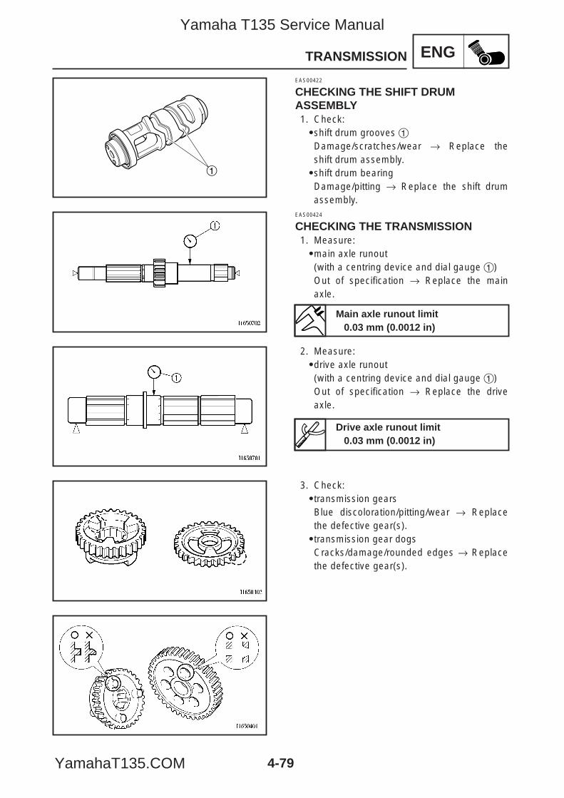
ENG
1
4-79
TRANSMISSION
EAS00422
CHECKING THE SHIFT DRUMASSEMBLY1. Check:9shift drum grooves 1Damage/scratches/wear → Replace theshift drum assembly.9shift drum bearingDamage/pitting → Replace the shift drumassembly.
EAS00424
CHECKING THE TRANSMISSION1. Measure:9main axle runout(with a centring device and dial gauge 1)Out of specification → Replace the mainaxle.
2. Measure:9drive axle runout(with a centring device and dial gauge 1)Out of specification → Replace the driveaxle.
3. Check:9transmission gearsBlue discoloration/pitting/wear → Replacethe defective gear(s).9transmission gear dogsCracks/damage/rounded edges → Replacethe defective gear(s).
Main axle runout limit0.03 mm (0.0012 in)
Drive axle runout limit0.03 mm (0.0012 in)
5YP-F8197-E0_4_1 05.6.27 19:33 Page 79
Yamaha T135 Service Manual
YamahaT135.COM
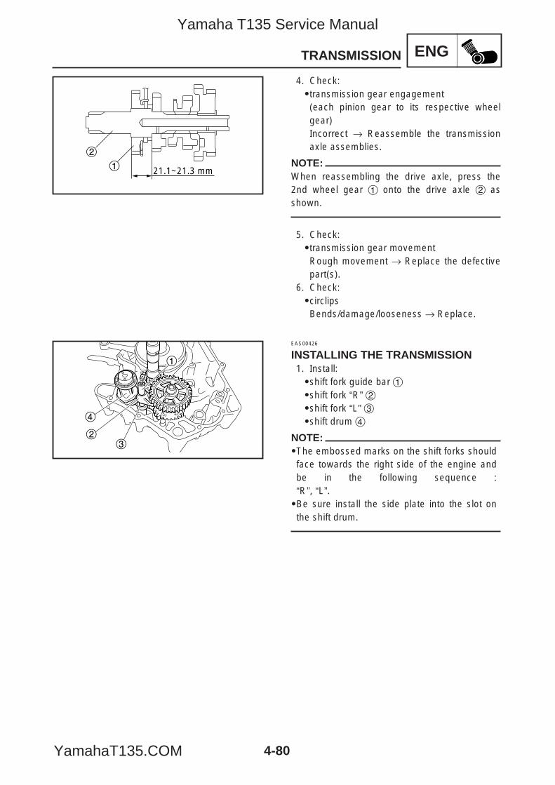
ENG
4-80
TRANSMISSION
21.1~21.3 mm1
2
4
23
1
4. Check:9transmission gear engagement(each pinion gear to its respective wheelgear)Incorrect → Reassemble the transmissionaxle assemblies.
NOTE:When reassembling the drive axle, press the2nd wheel gear 1 onto the drive axle 2 asshown.
5. Check:9transmission gear movementRough movement → Replace the defectivepart(s).
6. Check:9circlipsBends/damage/looseness → Replace.
EAS00426
INSTALLING THE TRANSMISSION1. Install:9shift fork guide bar 19shift fork “R” 29shift fork “L” 39shift drum 4
NOTE:9The embossed marks on the shift forks shouldface towards the right side of the engine andbe in the following sequence : “R”, “L”.9Be sure install the side plate into the slot onthe shift drum.
5YP-F8197-E0_4_1 05.6.27 19:33 Page 80
Yamaha T135 Service Manual
YamahaT135.COM
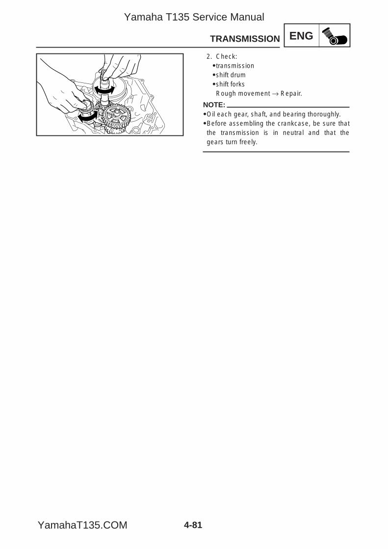
ENG
4-81
TRANSMISSION
2. Check:9transmission9shift drum9shift forksRough movement → Repair.
NOTE:9Oil each gear, shaft, and bearing thoroughly.9Before assembling the crankcase, be sure thatthe transmission is in neutral and that thegears turn freely.
5YP-F8197-E0_4_1 05.6.27 19:33 Page 81
Yamaha T135 Service Manual
YamahaT135.COM

ENG
5YP-F8197-E0_4_1 05.6.27 19:33 Page 82
Yamaha T135 Service Manual
YamahaT135.COM
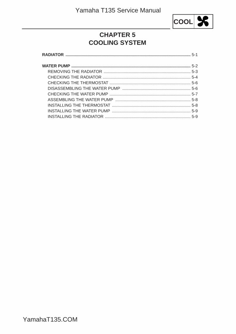
COOL
CHAPTER 5COOLING SYSTEM
RADIATOR ............................................................................................................ 5-1
WATER PUMP ....................................................................................................... 5-2REMOVING THE RADIATOR ........................................................................... 5-3CHECKING THE RADIATOR ............................................................................ 5-4CHECKING THE THERMOSTAT ...................................................................... 5-6DISASSEMBLING THE WATER PUMP ........................................................... 5-6CHECKING THE WATER PUMP ...................................................................... 5-7ASSEMBLING THE WATER PUMP ................................................................. 5-8INSTALLING THE THERMOSTAT .................................................................... 5-8INSTALLING THE WATER PUMP .................................................................... 5-9INSTALLING THE RADIATOR .......................................................................... 5-9
5YP-F8197-E0_5_1 05.6.27 19:34 Page A
Yamaha T135 Service Manual
YamahaT135.COM

COOL
5YP-F8197-E0_5_1 05.6.27 19:34 Page B
Yamaha T135 Service Manual
YamahaT135.COM
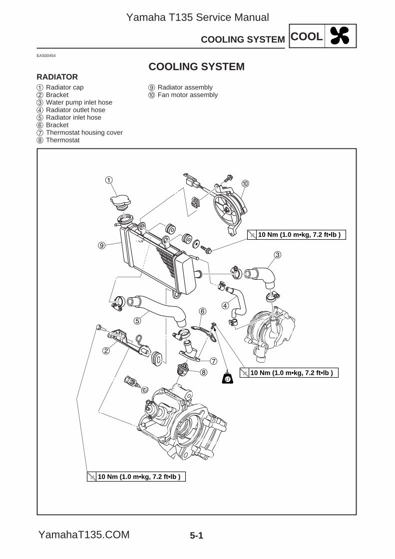
5-1
COOLCOOLING SYSTEM
EAS00454
COOLING SYSTEMRADIATOR
0
3
1
9
5
2
7
6
8
4
10 Nm (1.0 m•kg, 7.2 ft•lb )
10 Nm (1.0 m•kg, 7.2 ft•lb )
10 Nm (1.0 m•kg, 7.2 ft•lb )
1 Radiator cap2 Bracket3 Water pump inlet hose4 Radiator outlet hose5 Radiator inlet hose6 Bracket7 Thermostat housing cover8 Thermostat
9 Radiator assembly0 Fan motor assembly
5YP-F8197-E0_5_1 05.6.27 19:34 Page 1
Yamaha T135 Service Manual
YamahaT135.COM
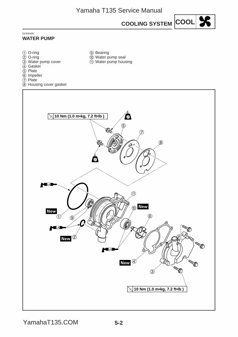
5-2
COOLCOOLING SYSTEM
EAS00468
WATER PUMP
5
7
8
6
0
q
1 9
2
4
3
LS
LS
LS
10 Nm (1.0 m•kg, 7.2 ft•lb )
10 Nm (1.0 m•kg, 7.2 ft•lb )
1 O-ring2 O-ring3 Water pump cover4 Gasket5 Plate6 Impeller7 Plate8 Housing cover gasket
9 Bearing 0 Water pump sealq Water pump housing
5YP-F8197-E0_5_1 05.6.27 19:34 Page 2
Yamaha T135 Service Manual
YamahaT135.COM
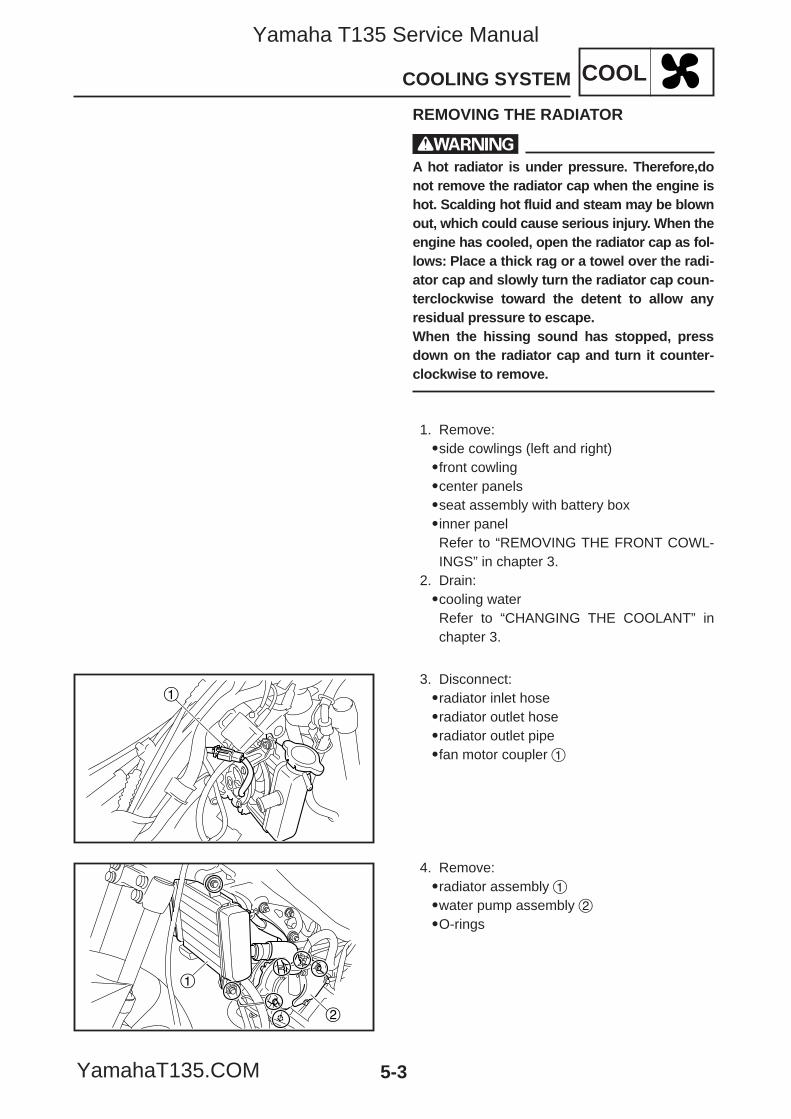
5-3
COOLCOOLING SYSTEM
REMOVING THE RADIATOR
wA hot radiator is under pressure. Therefore,donot remove the radiator cap when the engine ishot. Scalding hot fluid and steam may be blownout, which could cause serious injury. When theengine has cooled, open the radiator cap as fol-lows: Place a thick rag or a towel over the radi-ator cap and slowly turn the radiator cap coun-terclockwise toward the detent to allow anyresidual pressure to escape.When the hissing sound has stopped, pressdown on the radiator cap and turn it counter-clockwise to remove.
1. Remove:9side cowlings (left and right)9front cowling9center panels9seat assembly with battery box9inner panelRefer to “REMOVING THE FRONT COWL-INGS” in chapter 3.
2. Drain:9cooling waterRefer to “CHANGING THE COOLANT” inchapter 3.
3. Disconnect:9radiator inlet hose9radiator outlet hose9radiator outlet pipe9fan motor coupler 1
4. Remove:9radiator assembly 19water pump assembly 29O-rings
1
1
2
5YP-F8197-E0_5_1 05.6.27 19:34 Page 3
Yamaha T135 Service Manual
YamahaT135.COM
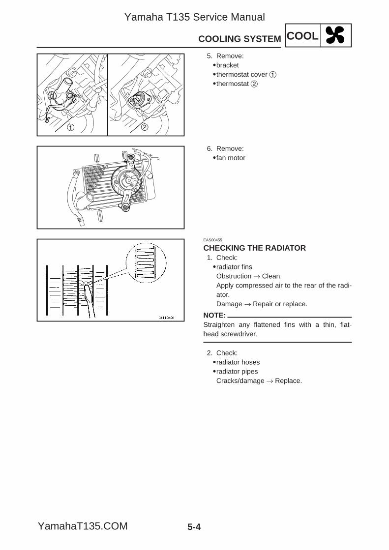
5-4
COOLCOOLING SYSTEM
1 2
5. Remove:9bracket9thermostat cover 19thermostat 2
6. Remove:9fan motor
EAS00455
CHECKING THE RADIATOR1. Check:9radiator finsObstruction → Clean.Apply compressed air to the rear of the radi-ator.Damage → Repair or replace.
NOTE:Straighten any flattened fins with a thin, flat-head screwdriver.
2. Check:9radiator hoses9radiator pipesCracks/damage → Replace.
5YP-F8197-E0_5_1 05.6.27 19:34 Page 4
Yamaha T135 Service Manual
YamahaT135.COM
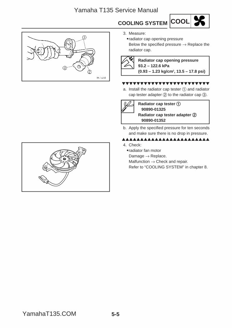
5-5
COOLCOOLING SYSTEM
3. Measure:9radiator cap opening pressureBelow the specified pressure → Replace theradiator cap.
a. Install the radiator cap tester 1 and radiatorcap tester adapter 2 to the radiator cap 3.
b. Apply the specified pressure for ten secondsand make sure there is no drop in pressure.
4. Check:9radiator fan motorDamage → Replace.Malfunction → Check and repair.Refer to “COOLING SYSTEM” in chapter 8.
Radiator cap opening pressure93.2 – 122.6 kPa(0.93 – 1.23 kg/cm2, 13.5 – 17.8 psi)
Radiator cap tester 1190890-01325
Radiator cap tester adapter 2290890-01352
5YP-F8197-E0_5_1 05.6.27 19:34 Page 5
Yamaha T135 Service Manual
YamahaT135.COM
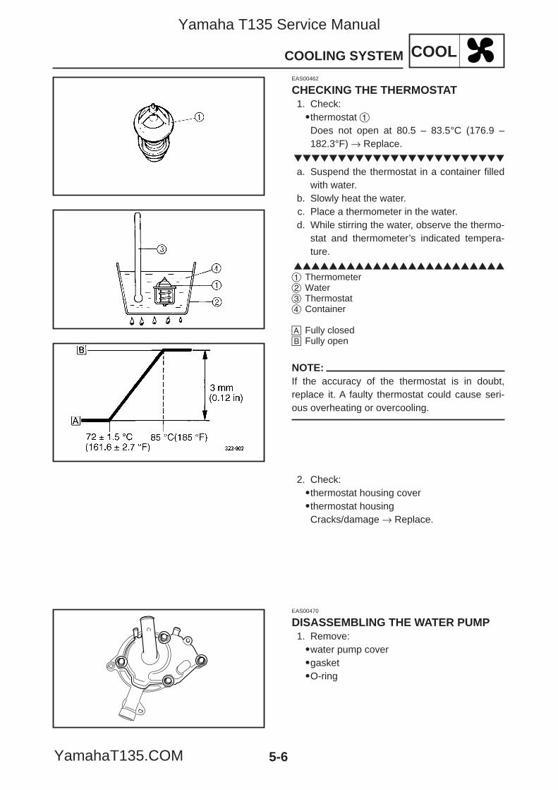
5-6
COOLCOOLING SYSTEM
EAS00462
CHECKING THE THERMOSTAT1. Check:9thermostat 1Does not open at 80.5 – 83.5°C (176.9 –182.3°F) → Replace.
a. Suspend the thermostat in a container filledwith water.
b. Slowly heat the water.c. Place a thermometer in the water.d. While stirring the water, observe the thermo-
stat and thermometer’s indicated tempera-ture.
1 Thermometer2 Water3 Thermostat4 Container
å Fully closed∫ Fully open
NOTE:If the accuracy of the thermostat is in doubt,replace it. A faulty thermostat could cause seri-ous overheating or overcooling.
2. Check:9thermostat housing cover9thermostat housingCracks/damage → Replace.
EAS00470
DISASSEMBLING THE WATER PUMP1. Remove:9water pump cover9gasket9O-ring
5YP-F8197-E0_5_1 05.6.27 19:34 Page 6
Yamaha T135 Service Manual
YamahaT135.COM
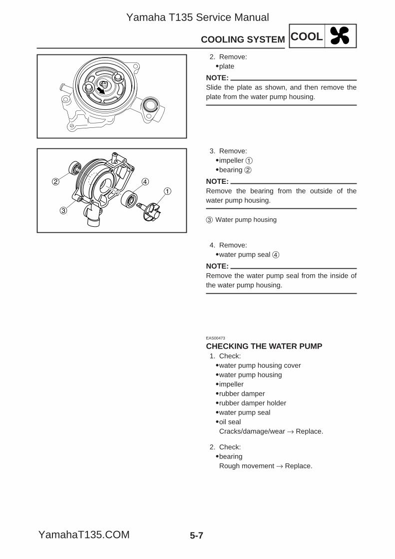
5-7
COOLCOOLING SYSTEM
2
1
4
3
3. Remove:9impeller 19bearing 2
NOTE:Remove the bearing from the outside of thewater pump housing.
3 Water pump housing
EAS00473
CHECKING THE WATER PUMP1. Check:9water pump housing cover9water pump housing9impeller9rubber damper9rubber damper holder9water pump seal9oil sealCracks/damage/wear → Replace.
4. Remove:9water pump seal 4
NOTE:Remove the water pump seal from the inside ofthe water pump housing.
2. Check:9bearingRough movement → Replace.
2. Remove:9plate
NOTE:Slide the plate as shown, and then remove theplate from the water pump housing.
5YP-F8197-E0_5_1 05.6.27 19:34 Page 7
Yamaha T135 Service Manual
YamahaT135.COM
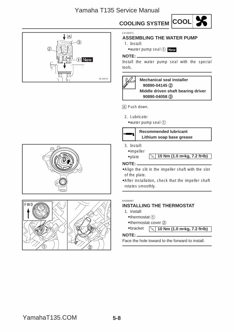
EAS00467
INSTALLING THE THERMOSTAT1. Install:9thermostat 19thermostat cover 29bracket
NOTE:Face the hole toward to the forward to install.
5-8
COOLCOOLING SYSTEM
21
FWD
10 Nm (1.0 m•kg, 7.2 ft•lb)
EAS00475
ASSEMBLING THE WATER PUMP1. Install:9water pump seal 1
NOTE:Install the water pump seal with the specialtools.
å Push down.
2. Lubricate:9water pump seal 1
Mechanical seal installer90890-04145 22
Middle driven shaft bearing driver90890-04058 33
Recommended lubricantLithium soap base grease
3. Install:9impeller9plate
NOTE:9Align the slit in the impeller shaft with the slotof the plate.9After installation, check that the impeller shaftrotates smoothly.
10 Nm (1.0 m•kg, 7.2 ft•lb)
5YP-F8197-E0_5_1 05.6.27 19:34 Page 8
Yamaha T135 Service Manual
YamahaT135.COM
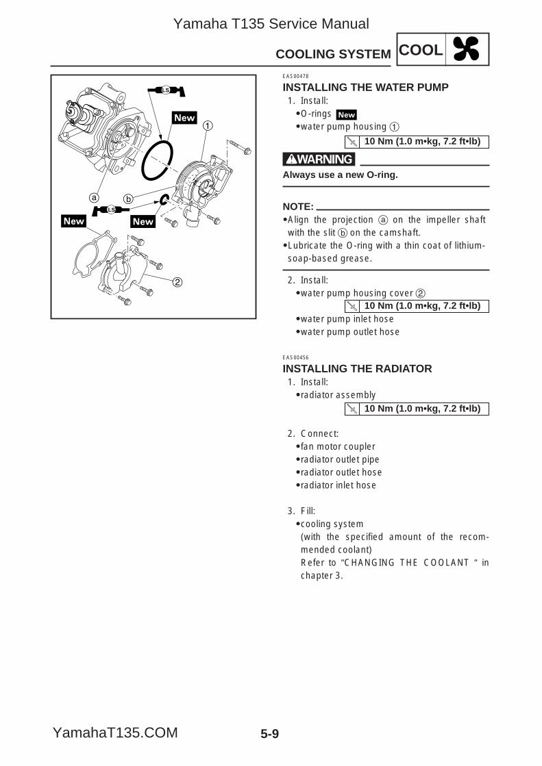
EAS00456
INSTALLING THE RADIATOR1. Install:9radiator assembly
2. Connect:9fan motor coupler9radiator outlet pipe9radiator outlet hose9radiator inlet hose
3. Fill:9cooling system(with the specified amount of the recom-mended coolant)Refer to “CHANGING THE COOLANT “ inchapter 3.
5-9
COOLCOOLING SYSTEM
1
2
a b
LS
LS
EAS00478
INSTALLING THE WATER PUMP1. Install:9O-rings9water pump housing 1
wAlways use a new O-ring.
NOTE:9Align the projection a on the impeller shaftwith the slit b on the camshaft.9Lubricate the O-ring with a thin coat of lithium-soap-based grease.
2. Install:9water pump housing cover 2
9water pump inlet hose9water pump outlet hose
10 Nm (1.0 m•kg, 7.2 ft•lb)
10 Nm (1.0 m•kg, 7.2 ft•lb)
10 Nm (1.0 m•kg, 7.2 ft•lb)
5YP-F8197-E0_5_1 05.6.27 19:34 Page 9
Yamaha T135 Service Manual
YamahaT135.COM
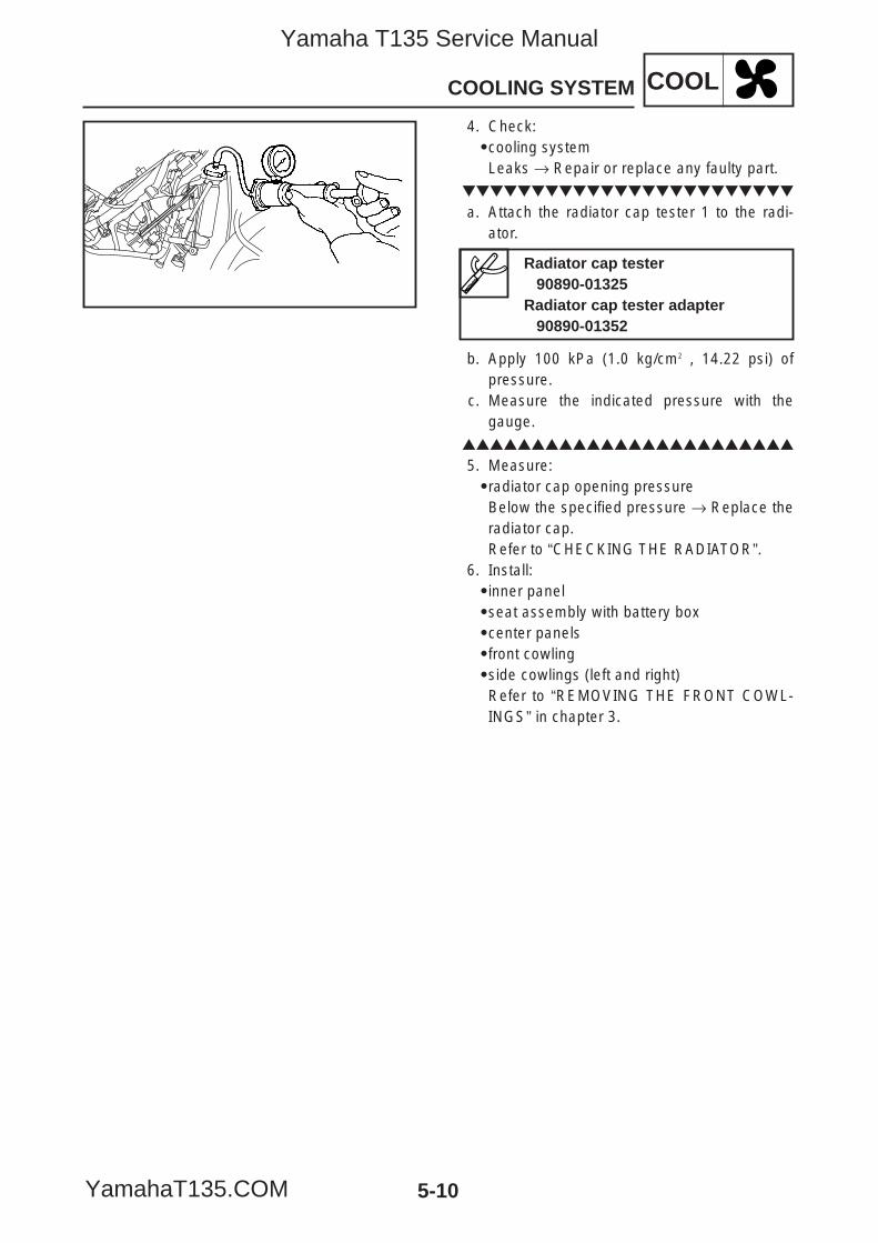
5-10
COOLCOOLING SYSTEM
4. Check:9cooling systemLeaks → Repair or replace any faulty part.
a. Attach the radiator cap tester 1 to the radi-ator.
b. Apply 100 kPa (1.0 kg/cm2 , 14.22 psi) ofpressure.
c. Measure the indicated pressure with thegauge.
5. Measure:9radiator cap opening pressureBelow the specified pressure → Replace theradiator cap.Refer to “CHECKING THE RADIATOR”.
6. Install:9inner panel9seat assembly with battery box9center panels9front cowling9side cowlings (left and right)Refer to “REMOVING THE FRONT COWL-INGS” in chapter 3.
Radiator cap tester90890-01325
Radiator cap tester adapter90890-01352
5YP-F8197-E0_5_1 05.6.27 19:34 Page 10
Yamaha T135 Service Manual
YamahaT135.COM
CARB
CHAPTER 6CARBURETOR
CARBURETOR ......................................................................................................6-1REMOVING THE CARBURETOR .....................................................................6-2DISASSEMBLING THE CARBURETOR ...........................................................6-5CHECKING THE CARBURETOR......................................................................6-6ASSEMBLING THE CARBURETOR .................................................................6-9INSTALLING THE CARBURETOR....................................................................6-10CHECKING AND ADJUSTING THE THROTTLE POSITION SENSOR............6-11CHECKING THE FUEL COCK OPERATION ....................................................6-13
AIR INDUCTION SYSTEM.....................................................................................6-14AIR INJECTION.................................................................................................6-14AIR CUT-OFF VALVE ........................................................................................6-14AIR INDUCTION SYSTEM DIAGRAMS............................................................6-15REMOVING THE AIR INDUCTION SYSTEM....................................................6-16CHECKING THE AIR INDUCTION SYSTEM ....................................................6-16INSTALLING THE AIR INDUCTION SYSTEM ..................................................6-16
5YP-F8197-E0_6 05.6.27 19:31 Page A
Yamaha T135 Service Manual
YamahaT135.COM

CARB
5YP-F8197-E0_6 05.6.27 19:31 Page B
Yamaha T135 Service Manual
YamahaT135.COM
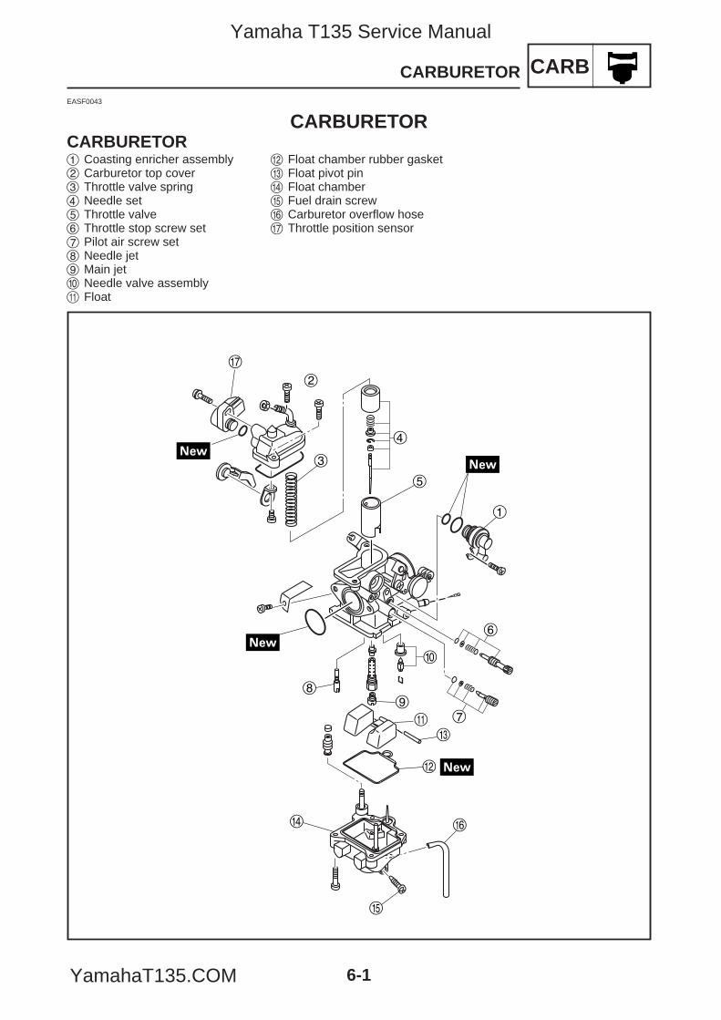
CARBCARBURETOR
6-1
EASF0043
CARBURETORCARBURETOR
t
1
4
5
3
2
6
7
0
9
q
8
e
w
r y
u
1 Coasting enricher assembly2 Carburetor top cover 3 Throttle valve spring 4 Needle set 5 Throttle valve 6 Throttle stop screw set 7 Pilot air screw set 8 Needle jet 9 Main jet 0 Needle valve assemblyq Float
w Float chamber rubber gaskete Float pivot pin r Float chambert Fuel drain screw y Carburetor overflow hoseu Throttle position sensor
5YP-F8197-E0_6 05.6.27 19:31 Page 1
Yamaha T135 Service Manual
YamahaT135.COM
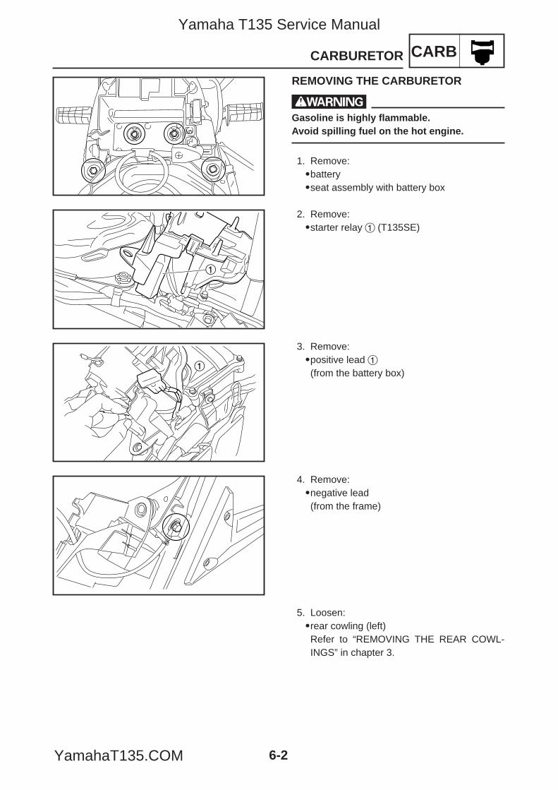
CARBCARBURETOR
6-2
REMOVING THE CARBURETOR
wGasoline is highly flammable.Avoid spilling fuel on the hot engine.
1. Remove:9battery9seat assembly with battery box
2. Remove:9starter relay 1 (T135SE)
3. Remove:9positive lead 1(from the battery box)
1
1
4. Remove:9negative lead(from the frame)
5. Loosen:9rear cowling (left)Refer to “REMOVING THE REAR COWL-INGS” in chapter 3.
5YP-F8197-E0_6 05.6.27 19:31 Page 2
Yamaha T135 Service Manual
YamahaT135.COM
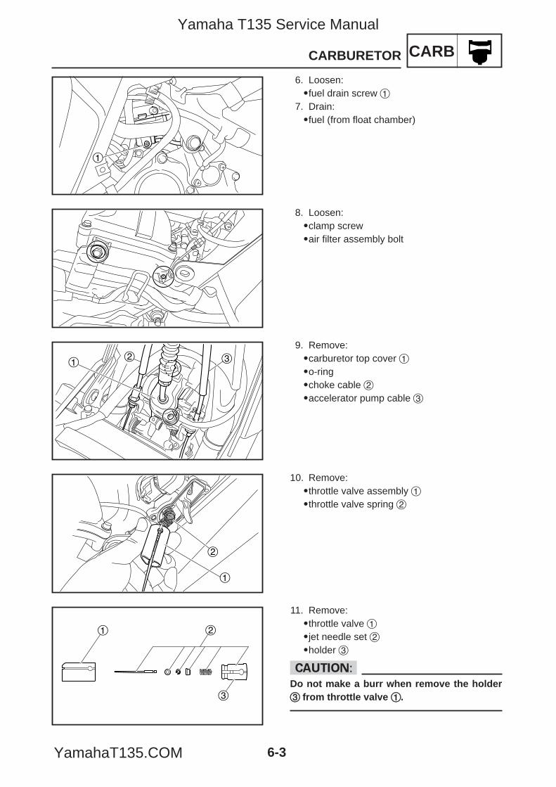
CARBCARBURETOR
6-3
6. Loosen:9fuel drain screw 1
7. Drain:9fuel (from float chamber)
1
12 3
2
1
8. Loosen:9clamp screw9air filter assembly bolt
9. Remove:9carburetor top cover 19o-ring9choke cable 29accelerator pump cable 3
10. Remove:9throttle valve assembly 19throttle valve spring 2
11. Remove:9throttle valve 19jet needle set 29holder 3
cCDo not make a burr when remove the holder33 from throttle valve 11.
1 2
3
5YP-F8197-E0_6 05.6.27 19:31 Page 3
Yamaha T135 Service Manual
YamahaT135.COM
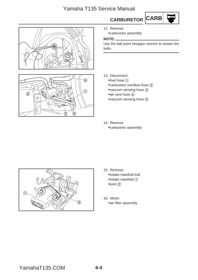
CARBCARBURETOR
6-4
12. Remove:9carburetor assembly
NOTE:Use the ball point hexagon wrench to loosen thebolts.
2
31
5
4
14. Remove:9carburetor assembly
13. Disconnect:9fuel hose 19carburetor overflow hose 29vacuum sensing hose 39air vent hose 49vacuum sensing hose 5
1
2
15. Remove:9intake manifold bolt9intake manifold 19joint 2
16. Move:9air filter assembly
5YP-F8197-E0_6 05.6.27 19:31 Page 4
Yamaha T135 Service Manual
YamahaT135.COM
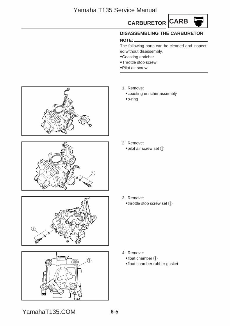
CARBCARBURETOR
6-5
1
1
1. Remove:9coasting enricher assembly9o-ring
2. Remove:9pilot air screw set 1
3. Remove:9throttle stop screw set 1
DISASSEMBLING THE CARBURETORNOTE:The following parts can be cleaned and inspect-ed without disassembly.9Coasting enricher9Throttle stop screw9Pilot air screw
1
4. Remove:9float chamber 19float chamber rubber gasket
5YP-F8197-E0_6 05.6.27 19:31 Page 5
Yamaha T135 Service Manual
YamahaT135.COM
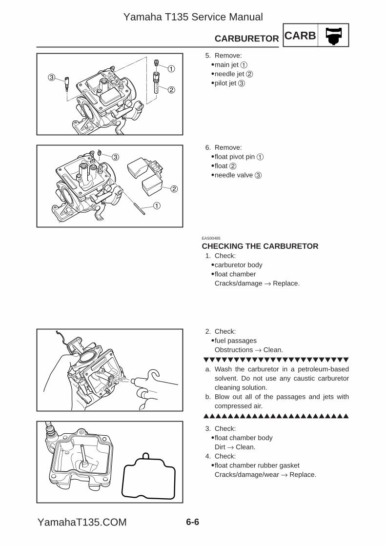
CARBCARBURETOR
6-6
3. Check:9float chamber bodyDirt → Clean.
4. Check:9float chamber rubber gasketCracks/damage/wear → Replace.
1
2
3
5. Remove:9main jet 19needle jet 29pilot jet 3
3
1
2
6. Remove:9float pivot pin 19float 29needle valve 3
EAS00485
CHECKING THE CARBURETOR1. Check:9carburetor body9float chamberCracks/damage → Replace.
2. Check:9fuel passagesObstructions → Clean.
a. Wash the carburetor in a petroleum-basedsolvent. Do not use any caustic carburetorcleaning solution.
b. Blow out all of the passages and jets withcompressed air.
5YP-F8197-E0_6 05.6.27 19:31 Page 6
Yamaha T135 Service Manual
YamahaT135.COM
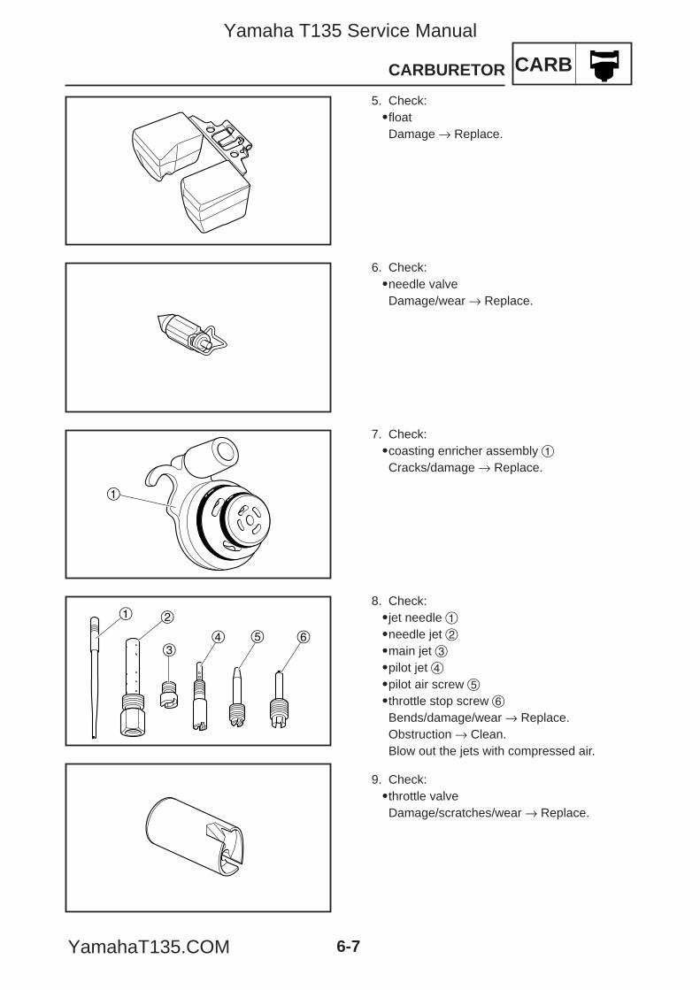
CARBCARBURETOR
6-7
1
1 2
34 5 6
6. Check:9needle valveDamage/wear → Replace.
7. Check:9coasting enricher assembly 1Cracks/damage → Replace.
8. Check:9jet needle 19needle jet 29main jet 39pilot jet 49pilot air screw 59throttle stop screw 6Bends/damage/wear → Replace.Obstruction → Clean.Blow out the jets with compressed air.
5. Check:9floatDamage → Replace.
9. Check:9throttle valveDamage/scratches/wear → Replace.
5YP-F8197-E0_6 05.6.27 19:31 Page 7
Yamaha T135 Service Manual
YamahaT135.COM
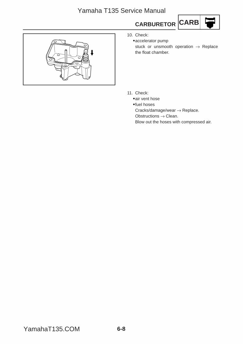
CARBCARBURETOR
6-8
10. Check:9accelerator pumpstuck or unsmooth operation → Replacethe float chamber.
11. Check:9air vent hose9fuel hosesCracks/damage/wear → Replace.Obstructions → Clean.Blow out the hoses with compressed air.
5YP-F8197-E0_6 05.6.27 19:31 Page 8
Yamaha T135 Service Manual
YamahaT135.COM
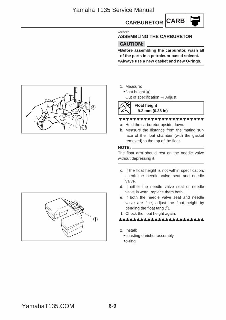
CARBCARBURETOR
6-9
EAS00487
ASSEMBLING THE CARBURETOR
cC99Before assembling the carburetor, wash allof the parts in a petroleum-based solvent.99Always use a new gasket and new O-rings.
1. Measure:9float height aOut of specification → Adjust.
a. Hold the carburetor upside down.b. Measure the distance from the mating sur-
face of the float chamber (with the gasketremoved) to the top of the float.
NOTE:The float arm should rest on the needle valvewithout depressing it.
c. If the float height is not within specification,check the needle valve seat and needlevalve.
d. If either the needle valve seat or needlevalve is worn, replace them both.
e. If both the needle valve seat and needlevalve are fine, adjust the float height bybending the float tang 1.
f. Check the float height again.
2. Install:9coasting enricher assembly9o-ring
Float height9.2 mm (0.36 in)
a
1
5YP-F8197-E0_6 05.6.27 19:31 Page 9
Yamaha T135 Service Manual
YamahaT135.COM
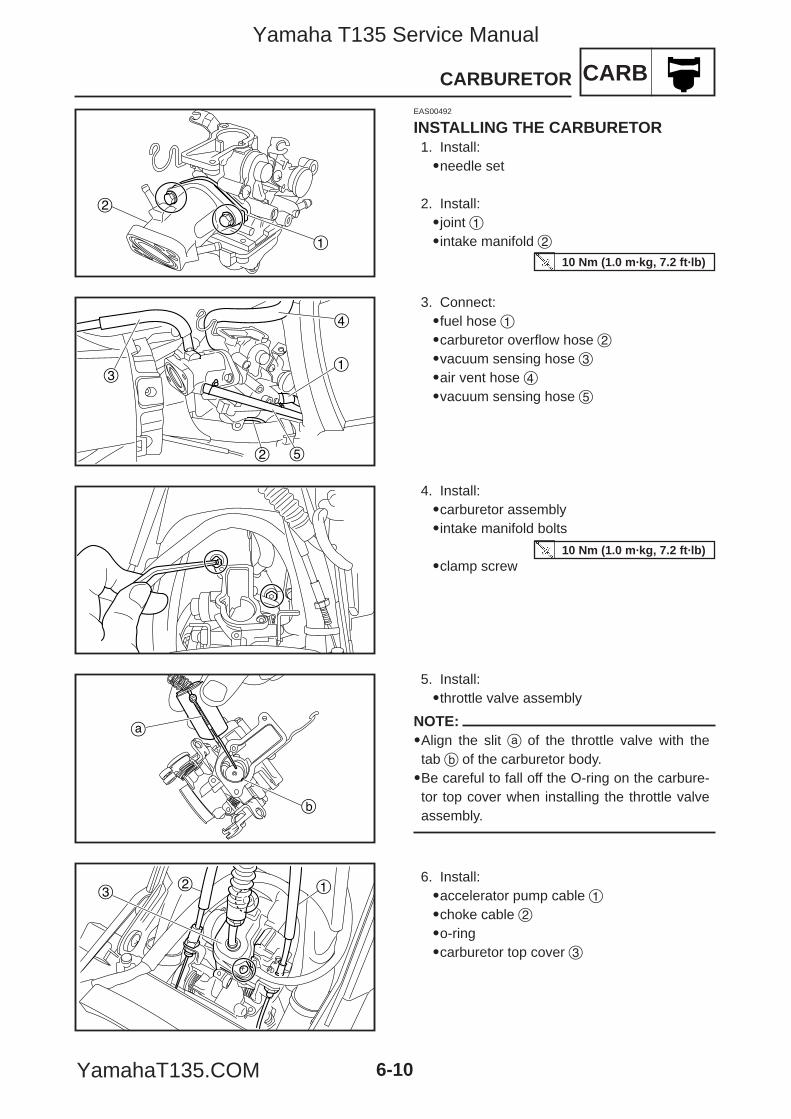
CARBCARBURETOR
6-10
2
1
2
31
5
4
a
b
32 1
EAS00492
INSTALLING THE CARBURETOR1. Install:9needle set
2. Install:9joint 19intake manifold 2
3. Connect:9fuel hose 19carburetor overflow hose 29vacuum sensing hose 39air vent hose 49vacuum sensing hose 5
4. Install:9carburetor assembly9intake manifold bolts
9clamp screw
5. Install:9throttle valve assembly
NOTE:9Align the slit a of the throttle valve with thetab b of the carburetor body.9Be careful to fall off the O-ring on the carbure-tor top cover when installing the throttle valveassembly.
6. Install:9accelerator pump cable 19choke cable 29o-ring9carburetor top cover 3
10 Nm (1.0 m·kg, 7.2 ft·lb)
10 Nm (1.0 m·kg, 7.2 ft·lb)
5YP-F8197-E0_6 05.6.27 19:31 Page 10
Yamaha T135 Service Manual
YamahaT135.COM
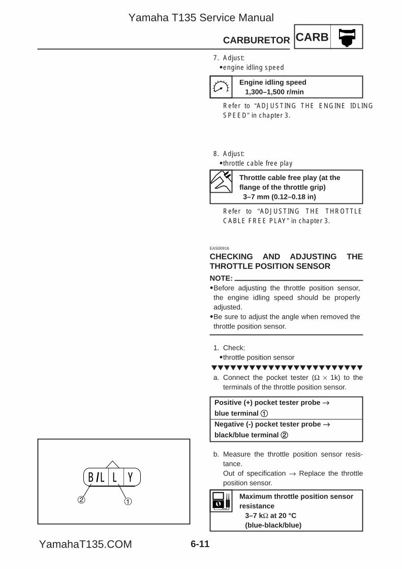
CARBCARBURETOR
6-11
EAS00916
CHECKING AND ADJUSTING THETHROTTLE POSITION SENSORNOTE:9Before adjusting the throttle position sensor,the engine idling speed should be properlyadjusted.9Be sure to adjust the angle when removed thethrottle position sensor.
1. Check:9throttle position sensor
a. Connect the pocket tester (Ω × 1k) to theterminals of the throttle position sensor.
b. Measure the throttle position sensor resis-tance.Out of specification → Replace the throttleposition sensor.B /L L Y
2 1Maximum throttle position sensorresistance
3–7 kΩ at 20 °C(blue-black/blue)
Positive (+) pocket tester probe →→blue terminal 11
Negative (-) pocket tester probe →→black/blue terminal 22
8. Adjust:9throttle cable free play
Refer to “ADJUSTING THE THROTTLECABLE FREE PLAY” in chapter 3.
Throttle cable free play (at theflange of the throttle grip)3–7 mm (0.12–0.18 in)
7. Adjust:9engine idling speed
Refer to “ADJUSTING THE ENGINE IDLINGSPEED” in chapter 3.
Engine idling speed1,300–1,500 r/min
5YP-F8197-E0_6 05.6.27 19:31 Page 11
Yamaha T135 Service Manual
YamahaT135.COM
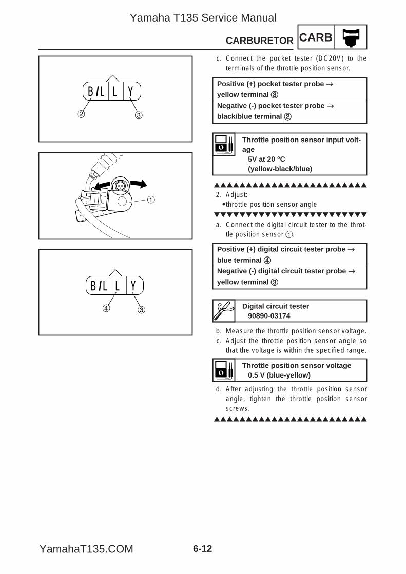
CARBCARBURETOR
6-12
c. Connect the pocket tester (DC20V) to theterminals of the throttle position sensor.
2. Adjust:9throttle position sensor angle
a. Connect the digital circuit tester to the throt-tle position sensor 1.
b. Measure the throttle position sensor voltage.c. Adjust the throttle position sensor angle so
that the voltage is within the specified range.
d. After adjusting the throttle position sensorangle, tighten the throttle position sensorscrews.
B /L L Y
2 3
1
B /L L Y
4 3
Throttle position sensor voltage0.5 V (blue-yellow)
Digital circuit tester90890-03174
Positive (+) digital circuit tester probe →→blue terminal 44
Negative (-) digital circuit tester probe →→yellow terminal 33
Throttle position sensor input volt-age
5V at 20 °C(yellow-black/blue)
Positive (+) pocket tester probe →→yellow terminal 33
Negative (-) pocket tester probe →→black/blue terminal 22
5YP-F8197-E0_6 05.6.27 19:31 Page 12
Yamaha T135 Service Manual
YamahaT135.COM
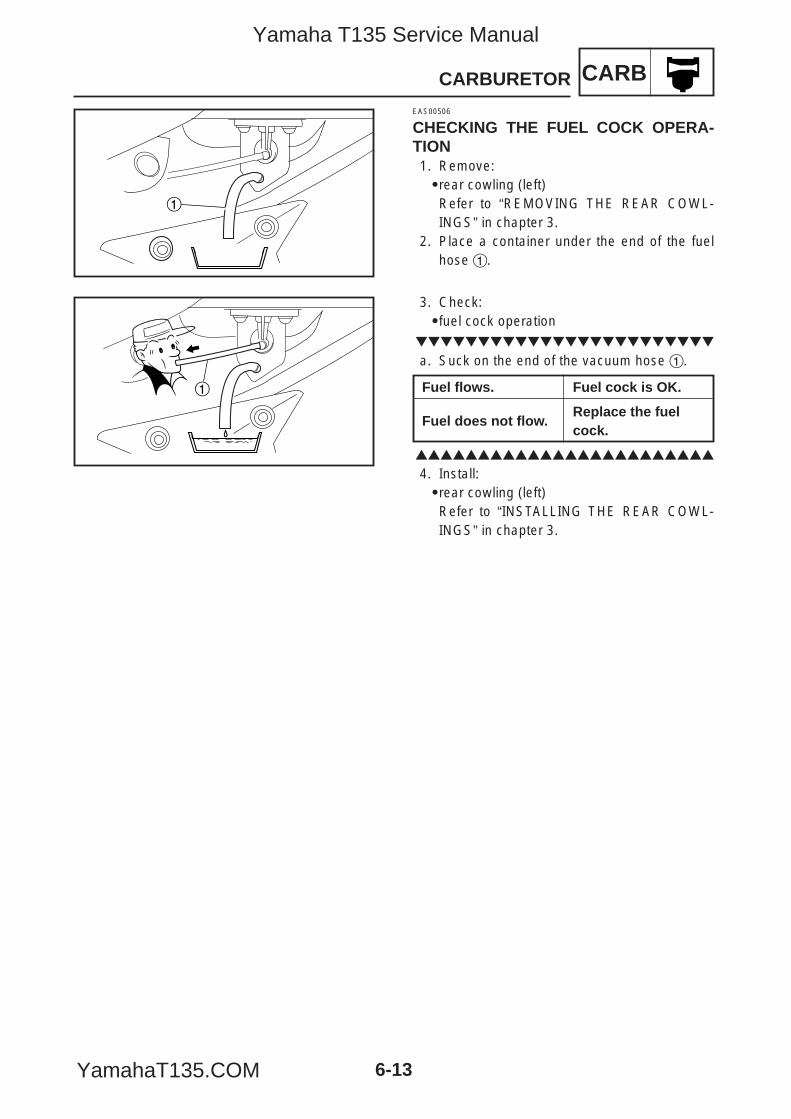
CARBCARBURETOR
6-13
1
EAS00506
CHECKING THE FUEL COCK OPERA-TION1. Remove:9rear cowling (left)Refer to “REMOVING THE REAR COWL-INGS” in chapter 3.
2. Place a container under the end of the fuelhose 1.
1
3. Check:9fuel cock operation
a. Suck on the end of the vacuum hose 1.
4. Install:9rear cowling (left)Refer to “INSTALLING THE REAR COWL-INGS” in chapter 3.
Fuel flows. Fuel cock is OK.
Fuel does not flow.Replace the fuel cock.
5YP-F8197-E0_6 05.6.27 19:31 Page 13
Yamaha T135 Service Manual
YamahaT135.COM
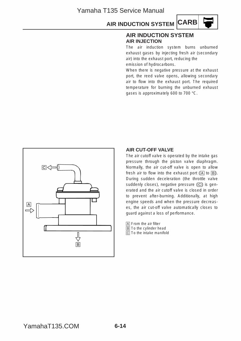
CARBAIR INDUCTION SYSTEM
6-14
AIR INDUCTION SYSTEMAIR INJECTIONThe air induction system burns unburnedexhaust gases by injecting fresh air (secondaryair) into the exhaust port, reducing theemission of hydrocarbons.When there is negative pressure at the exhaustport, the reed valve opens, allowing secondaryair to flow into the exhaust port. The requiredtemperature for burning the unburned exhaustgases is approximately 600 to 700 °C.
AIR CUT-OFF VALVEThe air cutoff valve is operated by the intake gaspressure through the piston valve diaphragm.Normally, the air cut-off valve is open to allowfresh air to flow into the exhaust port (å to ∫).During sudden deceleration (the throttle valvesuddenly closes), negative pressure (ç) is gen-erated and the air cutoff valve is closed in orderto prevent after-burning. Additionally, at highengine speeds and when the pressure decreas-es, the air cut-off valve automatically closes toguard against a loss of performance.
å From the air filter∫ To the cylinder headç To the intake manifold
å
∫
ç
5YP-F8197-E0_6 05.6.27 19:31 Page 14
Yamaha T135 Service Manual
YamahaT135.COM
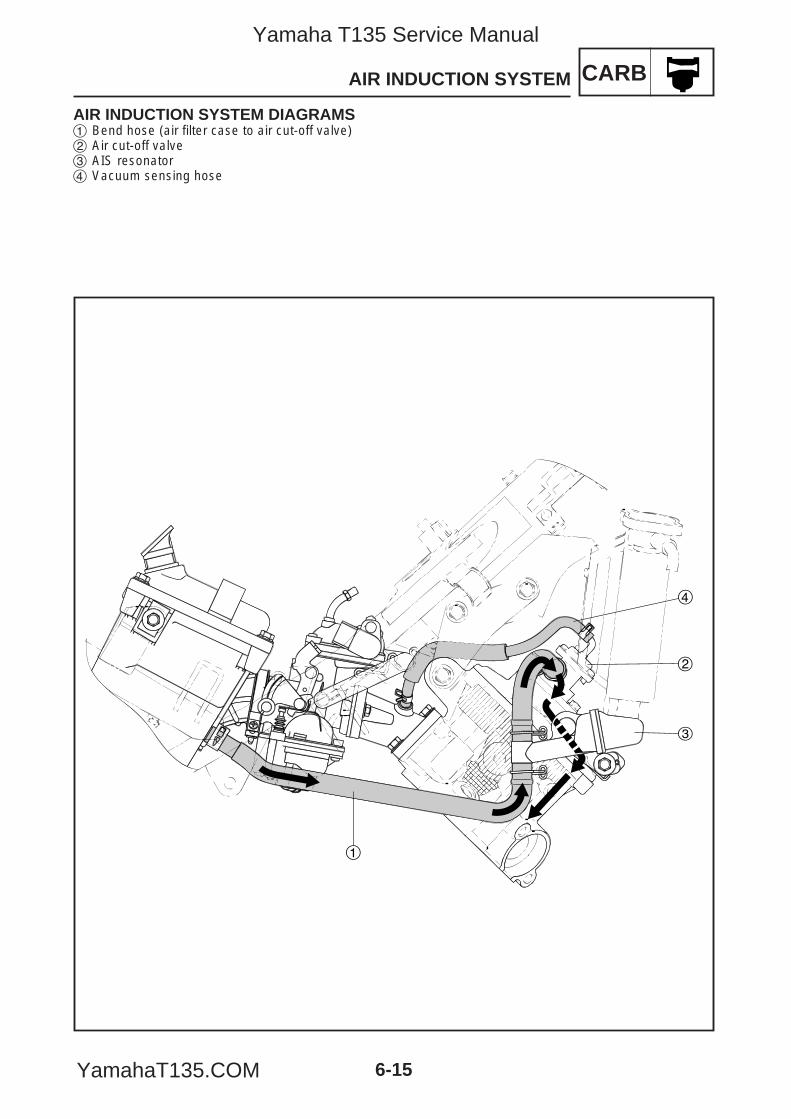
CARBAIR INDUCTION SYSTEM
6-15
AIR INDUCTION SYSTEM DIAGRAMS1 Bend hose (air filter case to air cut-off valve)2 Air cut-off valve3 AIS resonator4 Vacuum sensing hose
1
2
3
4
5YP-F8197-E0_6 05.6.27 19:31 Page 15
Yamaha T135 Service Manual
YamahaT135.COM
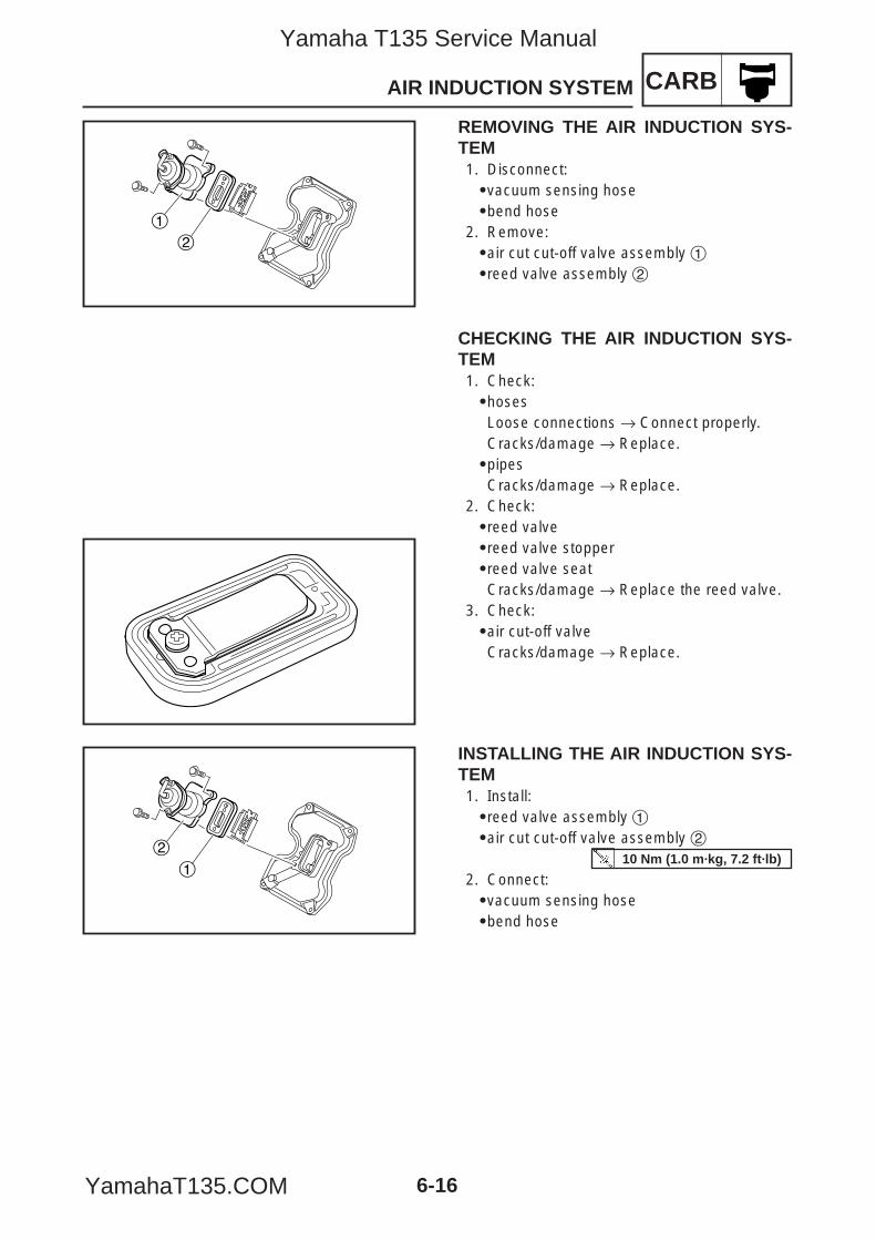
CARBAIR INDUCTION SYSTEM
6-16
CHECKING THE AIR INDUCTION SYS-TEM1. Check:9hosesLoose connections → Connect properly.Cracks/damage → Replace.9pipesCracks/damage → Replace.
2. Check:9reed valve9reed valve stopper9reed valve seatCracks/damage → Replace the reed valve.
3. Check:9air cut-off valveCracks/damage → Replace.
2
1
1
2
REMOVING THE AIR INDUCTION SYS-TEM1. Disconnect:9vacuum sensing hose9bend hose
2. Remove:9air cut cut-off valve assembly 19reed valve assembly 2
INSTALLING THE AIR INDUCTION SYS-TEM1. Install:9reed valve assembly 19air cut cut-off valve assembly 2
2. Connect:9vacuum sensing hose9bend hose
10 Nm (1.0 m·kg, 7.2 ft·lb)
5YP-F8197-E0_6 05.6.27 19:31 Page 16
Yamaha T135 Service Manual
YamahaT135.COM
CHAS
CHAPTER 7CHASSIS
FRONT WHEEL AND BRAKE DISC .....................................................................7-1REMOVING THE FRONT WHEEL ....................................................................7-2CHECKING THE FRONT WHEEL.....................................................................7-3CHECKING THE BRAKE DISC.........................................................................7-5CHECKING THE SPEEDOMETER GEAR UNIT...............................................7-6INSTALLING THE FRONT WHEEL...................................................................7-7
REAR WHEEL AND BRAKE .................................................................................7-8REMOVING THE REAR WHEEL ......................................................................7-9DISASSEMBLING THE BRAKE SHOE PLATE.................................................7-11CHECKING THE REAR WHEEL.......................................................................7-11CHECKING THE REAR WHEEL DRIVE HUB...................................................7-12CHECKING THE BRAKE...................................................................................7-13ASSEMBLING THE BRAKE SHOE PLATE.......................................................7-14INSTALLING THE REAR WHEEL .....................................................................7-14
FRONT BRAKE......................................................................................................7-16FRONT BRAKE CALIPER.................................................................................7-16REPLACING THE FRONT BRAKE PADS.........................................................7-17DISASSEMBLING THE FRONT BRAKE CALIPER ..........................................7-19CHECKING THE FRONT BRAKE CALIPER.....................................................7-21ASSEMBLING AND INSTALLING THE FRONT BRAKE CALIPER ..................7-22FRONT BRAKE MASTER CYLINDER ..............................................................7-24DISASSEMBLING THE FRONT BRAKE MASTER CYLINDER........................7-25CHECKING THE FRONT BRAKE MASTER CYLINDER ..................................7-26ASSEMBLING AND INSTALLING THE FRONT BRAKE MASTER CYLINDER......................................................7-27
FRONT FORK ........................................................................................................7-30REMOVING THE FRONT FORK LEGS ............................................................7-31DISASSEMBLING THE FRONT FORK LEGS ..................................................7-32CHECKING THE FRONT FORK LEGS.............................................................7-34ASSEMBLING THE FRONT FORK LEGS ........................................................7-35INSTALLING THE FRONT FORK LEGS ...........................................................7-37
HANDLEBAR.........................................................................................................7-39REMOVING THE HANDLEBAR ........................................................................7-40CHECKING THE HANDLEBAR.........................................................................7-42INSTALLING THE HANDLEBAR .......................................................................7-42
STEERING HEAD ..................................................................................................7-45REMOVING THE LOWER BRACKET...............................................................7-46CHECKING THE STEERING HEAD .................................................................7-46INSTALLING THE STEERING HEAD................................................................7-48
5YP-F8197-E0_7_1 05.6.27 19:29 Page A
Yamaha T135 Service Manual
YamahaT135.COM
CHAS
REAR SHOCK ABSORBER ASSEMBLY AND SWINGARM................................7-49REMOVING THE REAR SHOCK ABSORBER ASSEMBLIES AND SWINGARM ..............................................................................................7-50CHECKING THE REAR SHOCK ABSORBER ASSEMBLIES...........................7-52CHECKING THE SWINGARM...........................................................................7-53INSTALLING THE REAR SHOCK ABSORBER ASSEMBLIES AND SWINGARM ..............................................................................................7-53
DRIVE CHAIN AND SPROCKETS ........................................................................7-55REMOVING THE DRIVE CHAIN AND SPROCKETS .......................................7-56CHECKING THE DRIVE CHAIN........................................................................7-57INSTALLING THE DRIVE CHAIN AND SPROCKETS ......................................7-58
5YP-F8197-E0_7_1 05.6.27 19:29 Page B
Yamaha T135 Service Manual
YamahaT135.COM
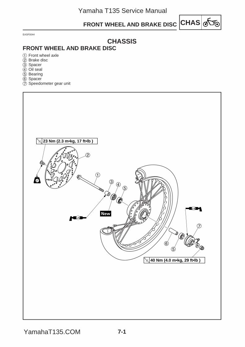
CHAS
7-1
FRONT WHEEL AND BRAKE DISC
EASF0044
CHASSISFRONT WHEEL AND BRAKE DISC
1
23 Nm (2.3 m•kg, 17 ft•lb )
LS
LS
40 Nm (4.0 m•kg, 29 ft•lb )
2
34
5
6
5
7
1 Front wheel axle2 Brake disc3 Spacer4 Oil seal5 Bearing6 Spacer7 Speedometer gear unit
5YP-F8197-E0_7_1 05.6.27 19:29 Page 1
Yamaha T135 Service Manual
YamahaT135.COM
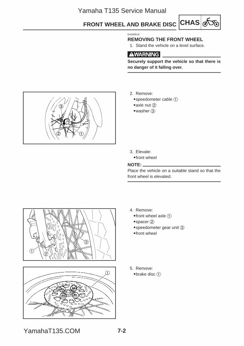
CHASFRONT WHEEL AND BRAKE DISC
7-2
1
3
2
12
3
EAS00519
REMOVING THE FRONT WHEEL1. Stand the vehicle on a level surface.
wSecurely support the vehicle so that there isno danger of it falling over.
2. Remove:9speedometer cable 19axle nut 29washer 3
3. Elevate:9front wheel
NOTE:Place the vehicle on a suitable stand so that thefront wheel is elevated.
4. Remove:9front wheel axle 19spacer 29speedometer gear unit 39front wheel
5. Remove:9brake disc 1
5YP-F8197-E0_7_1 05.6.27 19:29 Page 2
Yamaha T135 Service Manual
YamahaT135.COM
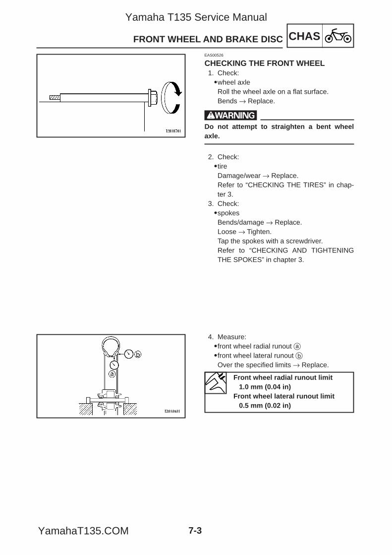
CHASFRONT WHEEL AND BRAKE DISC
7-3
EAS00526
CHECKING THE FRONT WHEEL1. Check:9wheel axleRoll the wheel axle on a flat surface.Bends → Replace.
wDo not attempt to straighten a bent wheelaxle.
2. Check:9tireDamage/wear → Replace.Refer to “CHECKING THE TIRES” in chap-ter 3.
3. Check:9spokesBends/damage → Replace.Loose → Tighten.Tap the spokes with a screwdriver.Refer to “CHECKING AND TIGHTENINGTHE SPOKES” in chapter 3.
4. Measure:9front wheel radial runout a9front wheel lateral runout bOver the specified limits → Replace.
Front wheel radial runout limit1.0 mm (0.04 in)
Front wheel lateral runout limit0.5 mm (0.02 in)
5YP-F8197-E0_7_1 05.6.27 19:29 Page 3
Yamaha T135 Service Manual
YamahaT135.COM
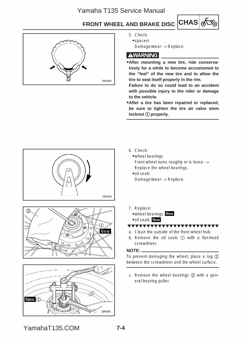
CHASFRONT WHEEL AND BRAKE DISC
7-4
New1
2
5. Check:9spacersDamage/wear → Replace.
w99After mounting a new tire, ride conserva-tively for a while to become accustomed tothe “feel” of the new tire and to allow thetire to seat itself properly in the rim. Failure to do so could lead to an accidentwith possible injury to the rider or damageto the vehicle.99After a tire has been repaired or replaced,be sure to tighten the tire air valve stemlocknut 11 properly.
6. Check:9wheel bearingsFront wheel turns roughly or is loose →Replace the wheel bearings.9oil sealsDamage/wear → Replace.
7. Replace:9wheel bearings 9oil seals
a. Clean the outside of the front wheel hub.b. Remove the oil seals 1 with a flat-head
screwdriver.
NOTE:To prevent damaging the wheel, place a rag 2between the screwdriver and the wheel surface.
c. Remove the wheel bearings 3 with a gen-eral bearing puller.
5YP-F8197-E0_7_1 05.6.27 19:29 Page 4
Yamaha T135 Service Manual
YamahaT135.COM
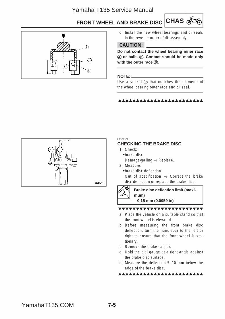
CHASFRONT WHEEL AND BRAKE DISC
7-5
d. Install the new wheel bearings and oil sealsin the reverse order of disassembly.
cCDo not contact the wheel bearing inner race44 or balls 55. Contact should be made onlywith the outer race 66.
NOTE:Use a socket 7 that matches the diameter ofthe wheel bearing outer race and oil seal.
EAS00527
CHECKING THE BRAKE DISC1. Check:9brake discDamage/galling → Replace.
2. Measure:9brake disc deflectionOut of specification → Correct the brakedisc deflection or replace the brake disc.
a. Place the vehicle on a suitable stand so thatthe front wheel is elevated.
b. Before measuring the front brake discdeflection, turn the handlebar to the left orright to ensure that the front wheel is sta-tionary.
c. Remove the brake caliper.d. Hold the dial gauge at a right angle against
the brake disc surface.e. Measure the deflection 5–10 mm below the
edge of the brake disc.
Brake disc deflection limit (maxi-mum)
0.15 mm (0.0059 in)
5YP-F8197-E0_7_1 05.6.27 19:29 Page 5
Yamaha T135 Service Manual
YamahaT135.COM
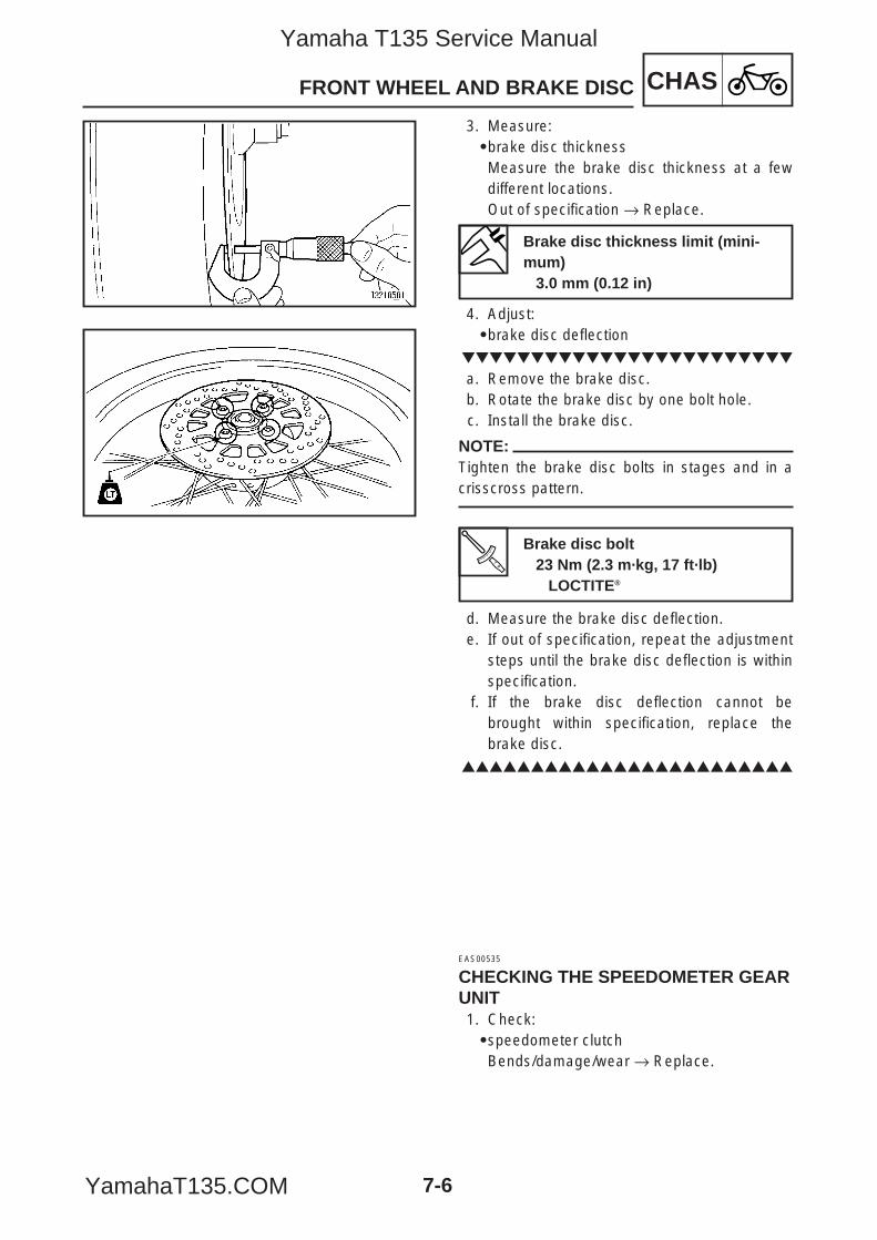
CHASFRONT WHEEL AND BRAKE DISC
7-6
3. Measure:9brake disc thicknessMeasure the brake disc thickness at a fewdifferent locations.Out of specification → Replace.
4. Adjust:9brake disc deflection
a. Remove the brake disc.b. Rotate the brake disc by one bolt hole.c. Install the brake disc.
NOTE:Tighten the brake disc bolts in stages and in acrisscross pattern.
d. Measure the brake disc deflection.e. If out of specification, repeat the adjustment
steps until the brake disc deflection is withinspecification.
f. If the brake disc deflection cannot bebrought within specification, replace thebrake disc.
EAS00535
CHECKING THE SPEEDOMETER GEARUNIT1. Check:9speedometer clutchBends/damage/wear → Replace.
Brake disc thickness limit (mini-mum)
3.0 mm (0.12 in)
Brake disc bolt23 Nm (2.3 m·kg, 17 ft·lb)
LOCTITE®
5YP-F8197-E0_7_1 05.6.27 19:29 Page 6
Yamaha T135 Service Manual
YamahaT135.COM
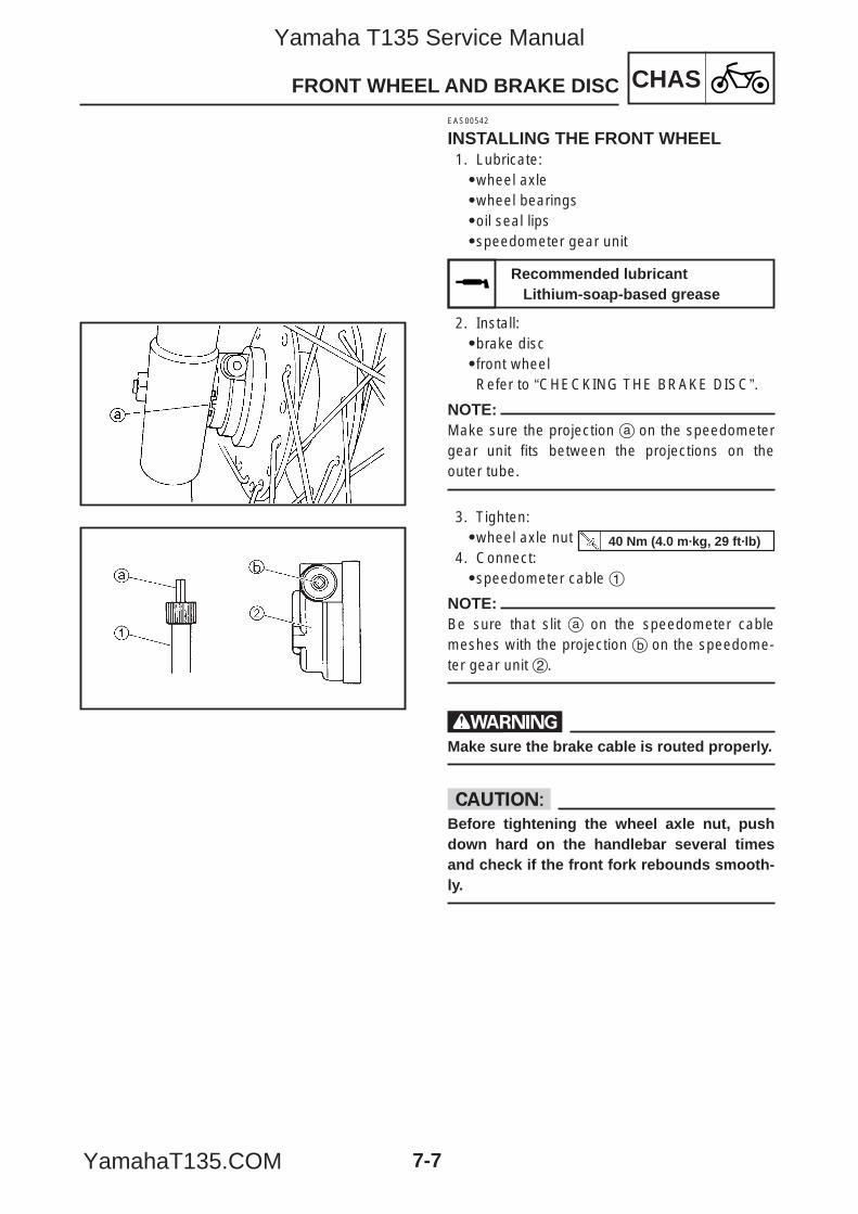
CHASFRONT WHEEL AND BRAKE DISC
7-7
EAS00542
INSTALLING THE FRONT WHEEL1. Lubricate:9wheel axle9wheel bearings9oil seal lips9speedometer gear unit
2. Install:9brake disc9front wheelRefer to “CHECKING THE BRAKE DISC”.
NOTE:Make sure the projection a on the speedometergear unit fits between the projections on theouter tube.
3. Tighten:9wheel axle nut
4. Connect:9speedometer cable 1
NOTE:Be sure that slit a on the speedometer cablemeshes with the projection b on the speedome-ter gear unit 2.
wMake sure the brake cable is routed properly.
cCBefore tightening the wheel axle nut, pushdown hard on the handlebar several timesand check if the front fork rebounds smooth-ly.
Recommended lubricantLithium-soap-based grease
40 Nm (4.0 m·kg, 29 ft·lb)
5YP-F8197-E0_7_1 05.6.27 19:29 Page 7
Yamaha T135 Service Manual
YamahaT135.COM
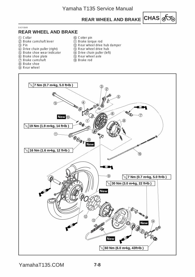
CHASREAR WHEEL AND BRAKE
7-8
EASF0049
REAR WHEEL AND BRAKE
LS
LS
7 Nm (0.7 m•kg, 5.0 ft•lb )
t
19 Nm (1.9 m•kg, 14 ft•lb )
16 Nm (1.6 m•kg, 12 ft•lb )
7 Nm (0.7 m•kg, 5.0 ft•lb )
60 Nm (6.0 m•kg, 43ft•lb )
30 Nm (3.0 m•kg, 22 ft•lb )
0
0
8
LS
4
7
y
9
1
32
5
6
q
LS
we r
LS
1 Collar2 Brake camshaft lever 3 Pin 4 Drive chain puller (right) 5 Brake shoe wear indicator 6 Brake shoe plate 7 Brake camshaft 8 Brake shoe9 Rear wheel
0 Cotter pinq Brake torque rodw Rear wheel drive hub dampere Rear wheel drive hubr Drive chain puller (left)t Rear wheel axley Brake rod
5YP-F8197-E0_7_1 05.6.27 19:29 Page 8
Yamaha T135 Service Manual
YamahaT135.COM
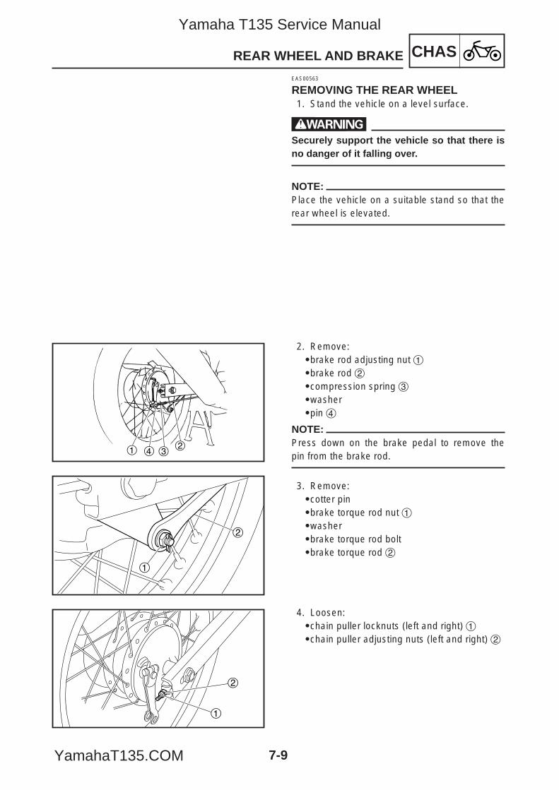
CHASREAR WHEEL AND BRAKE
7-9
1 4 32
1
2
1
2
EAS00563
REMOVING THE REAR WHEEL1. Stand the vehicle on a level surface.
wSecurely support the vehicle so that there isno danger of it falling over.
NOTE:Place the vehicle on a suitable stand so that therear wheel is elevated.
2. Remove:9brake rod adjusting nut 19brake rod 29compression spring 39washer9pin 4
NOTE:Press down on the brake pedal to remove thepin from the brake rod.
3. Remove:9cotter pin9brake torque rod nut 19washer9brake torque rod bolt9brake torque rod 2
4. Loosen:9chain puller locknuts (left and right) 19chain puller adjusting nuts (left and right) 2
5YP-F8197-E0_7_1 05.6.27 19:29 Page 9
Yamaha T135 Service Manual
YamahaT135.COM
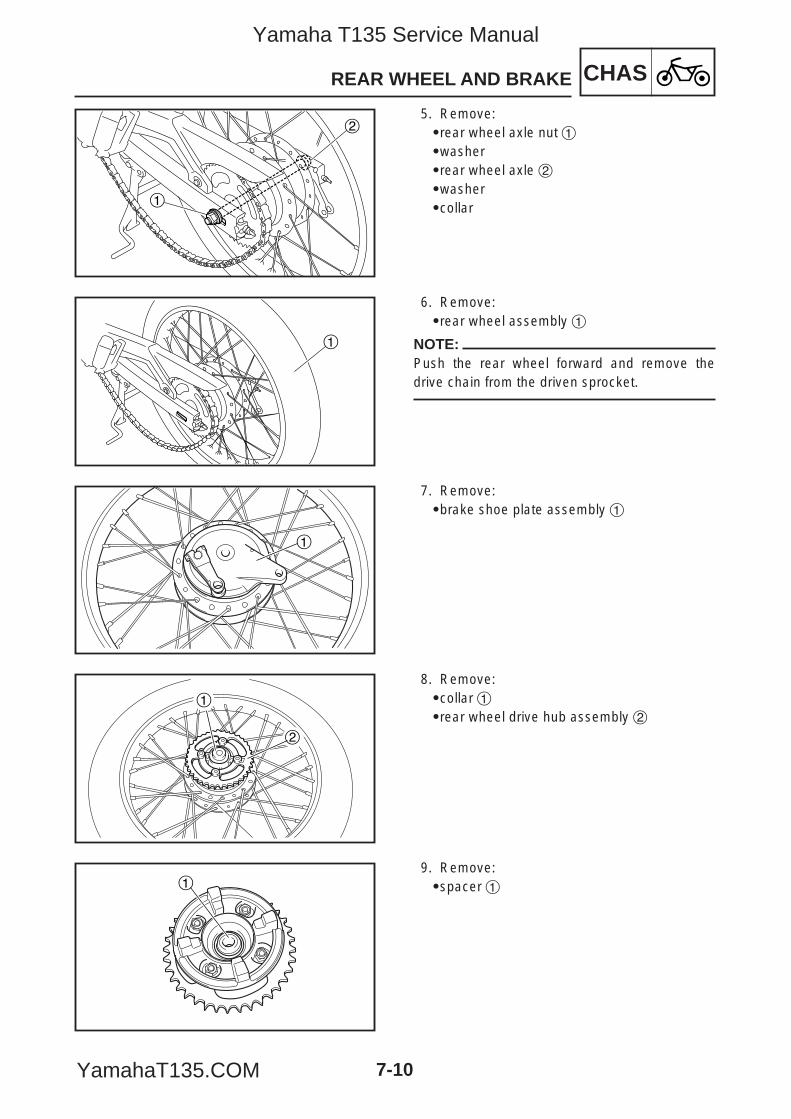
CHASREAR WHEEL AND BRAKE
7-10
1
2
1
1
1
2
1
5. Remove:9rear wheel axle nut 19washer9rear wheel axle 29washer9collar
6. Remove:9rear wheel assembly 1
NOTE:Push the rear wheel forward and remove thedrive chain from the driven sprocket.
7. Remove:9brake shoe plate assembly 1
8. Remove:9collar 19rear wheel drive hub assembly 2
9. Remove:9spacer 1
5YP-F8197-E0_7_1 05.6.27 19:29 Page 10
Yamaha T135 Service Manual
YamahaT135.COM
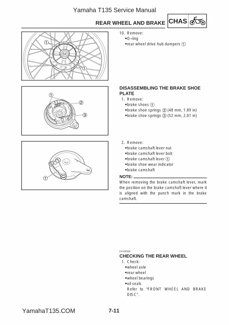
CHASREAR WHEEL AND BRAKE
7-11
1
1
1
3
2
1
10. Remove:9O-ring9rear wheel drive hub dampers 1
DISASSEMBLING THE BRAKE SHOEPLATE1. Remove:9brake shoes 19brake shoe springs 2 (48 mm, 1.89 in)9brake shoe springs 3 (52 mm, 2.01 in)
2. Remove:9brake camshaft lever nut9brake camshaft lever bolt9brake camshaft lever 19brake shoe wear indicator9brake camshaft
NOTE:When removing the brake camshaft lever, markthe position on the brake camshaft lever where itis aligned with the punch mark in the brakecamshaft.
EAS00566
CHECKING THE REAR WHEEL1. Check:9wheel axle9rear wheel9wheel bearings9oil sealsRefer to “FRONT WHEEL AND BRAKEDISC”.
5YP-F8197-E0_7_1 05.6.27 19:29 Page 11
Yamaha T135 Service Manual
YamahaT135.COM
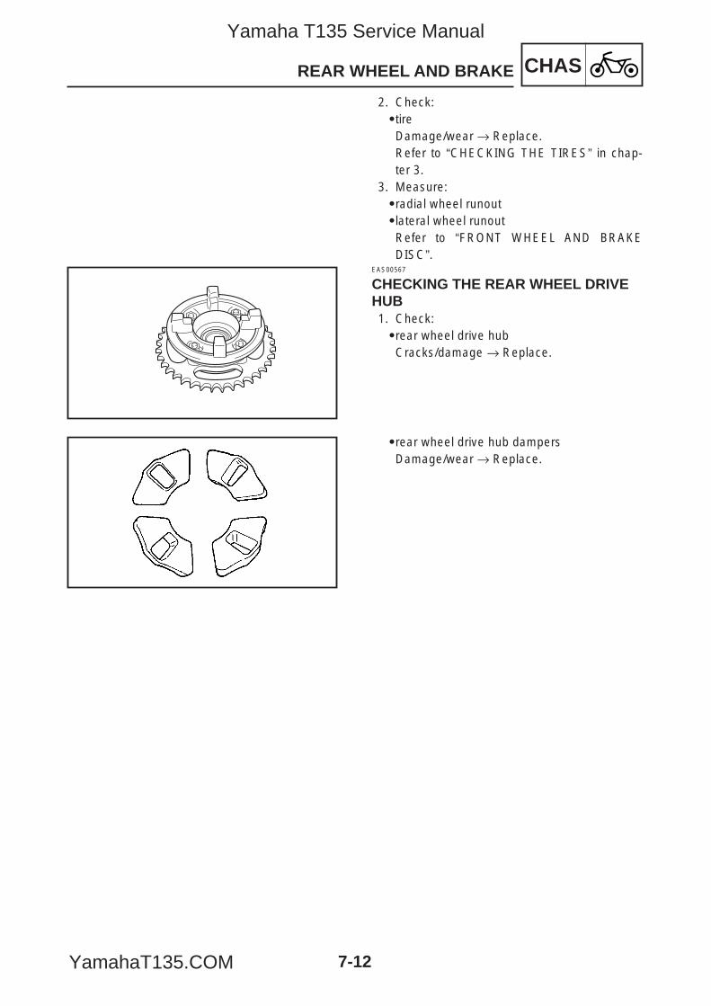
CHASREAR WHEEL AND BRAKE
7-12
2. Check:9tireDamage/wear → Replace.Refer to “CHECKING THE TIRES” in chap-ter 3.
3. Measure:9radial wheel runout9lateral wheel runoutRefer to “FRONT WHEEL AND BRAKEDISC”.
EAS00567
CHECKING THE REAR WHEEL DRIVEHUB1. Check:9rear wheel drive hubCracks/damage → Replace.
9rear wheel drive hub dampersDamage/wear → Replace.
5YP-F8197-E0_7_1 05.6.27 19:29 Page 12
Yamaha T135 Service Manual
YamahaT135.COM
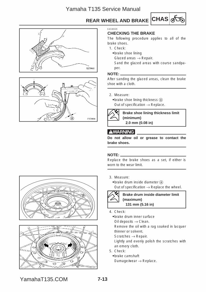
CHASREAR WHEEL AND BRAKE
7-13
a
EAS00539
CHECKING THE BRAKEThe following procedure applies to all of thebrake shoes.1. Check:9brake shoe liningGlazed areas → Repair.Sand the glazed areas with course sandpa-per.
NOTE:After sanding the glazed areas, clean the brakeshoe with a cloth.
2. Measure:9brake shoe lining thickness aOut of specification → Replace.
wDo not allow oil or grease to contact thebrake shoes.
NOTE:Replace the brake shoes as a set, if either isworn to the wear limit.
3. Measure:9brake drum inside diameter aOut of specification → Replace the wheel.
4. Check:9brake drum inner surfaceOil deposits → Clean.Remove the oil with a rag soaked in lacquerthinner or solvent.Scratches → Repair.Lightly and evenly polish the scratches withan emery cloth.
5. Check:9brake camshaftDamage/wear → Replace.
Brake shoe lining thickness limit(minimum)
2.0 mm (0.08 in)
Brake drum inside diameter limit(maximum)
131 mm (5.16 in)
5YP-F8197-E0_7_1 05.6.27 19:29 Page 13
Yamaha T135 Service Manual
YamahaT135.COM
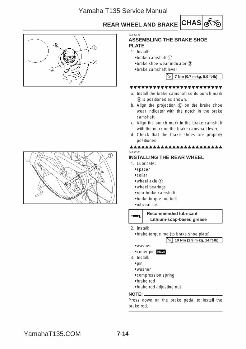
CHASREAR WHEEL AND BRAKE
7-14
1
EAS00570
ASSEMBLING THE BRAKE SHOEPLATE1. Install:9brake camshaft 19brake shoe wear indicator 29brake camshaft lever
a. Install the brake camshaft so its punch marka is positioned as shown.
b. Align the projection b on the brake shoewear indicator with the notch in the brakecamshaft.
c. Align the punch mark in the brake camshaftwith the mark on the brake camshaft lever.
d. Check that the brake shoes are properlypositioned.
EAS00571
INSTALLING THE REAR WHEEL1. Lubricate:9spacer9collar9wheel axle 19wheel bearings9rear brake camshaft9brake torque rod bolt9oil seal lips
2. Install:9brake torque rod (to brake shoe plate)
9washer9cotter pin
3. Install:9pin9washer9compression spring9brake rod9brake rod adjusting nut
NOTE:Press down on the brake pedal to install thebrake rod.
Recommended lubricantLithium-soap-based grease
19 Nm (1.9 m·kg, 14 ft·lb)
7 Nm (0.7 m·kg, 5.0 ft·lb)
5YP-F8197-E0_7_1 05.6.27 19:29 Page 14
Yamaha T135 Service Manual
YamahaT135.COM
CHASREAR WHEEL AND BRAKE
7-15
4. Adjust:9drive chain slack
Refer to “ADJUSTING THE DRIVE CHAINSLACK” in chapter 3.
5. Tighten:9wheel axle nut
cCDo not loosen the wheel axle nut after tight-ening it to the specified torque.
Drive chain slack25–35 mm (0.98–1.38 in)
60 Nm (6.0 m·kg, 43 ft·lb)
5YP-F8197-E0_7_1 05.6.27 19:29 Page 15
Yamaha T135 Service Manual
YamahaT135.COM
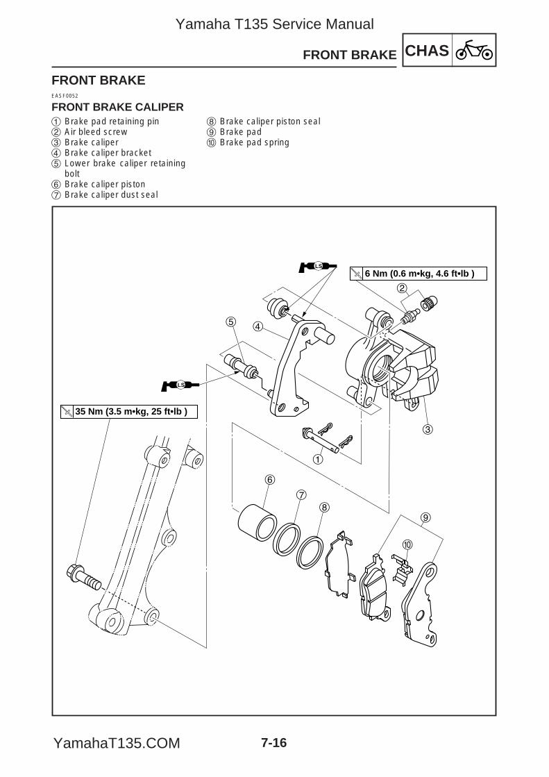
7-16
CHASFRONT BRAKE
FRONT BRAKEEASF0052
FRONT BRAKE CALIPER
35 Nm (3.5 m•kg, 25 ft•lb )
3
2
LS
4
1
5
LS
6 Nm (0.6 m•kg, 4.6 ft•lb )
6
7
89
0
1 Brake pad retaining pin2 Air bleed screw 3 Brake caliper 4 Brake caliper bracket5 Lower brake caliper retaining
bolt6 Brake caliper piston7 Brake caliper dust seal
8 Brake caliper piston seal9 Brake pad0 Brake pad spring
5YP-F8197-E0_7_1 05.6.27 19:29 Page 16
Yamaha T135 Service Manual
YamahaT135.COM
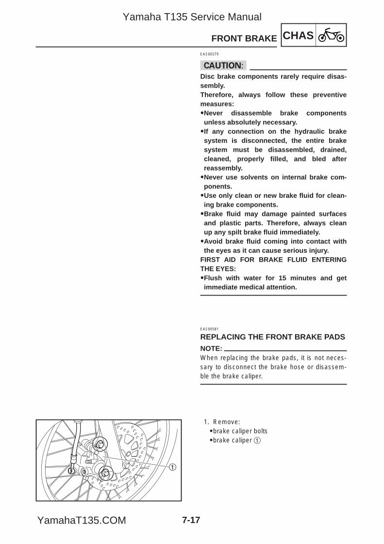
CHASFRONT BRAKE
7-17
1
EAS00579
cCDisc brake components rarely require disas-sembly.Therefore, always follow these preventivemeasures:99Never disassemble brake componentsunless absolutely necessary.99If any connection on the hydraulic brakesystem is disconnected, the entire brakesystem must be disassembled, drained,cleaned, properly filled, and bled afterreassembly.99Never use solvents on internal brake com-ponents.99Use only clean or new brake fluid for clean-ing brake components.99Brake fluid may damage painted surfacesand plastic parts. Therefore, always cleanup any spilt brake fluid immediately.99Avoid brake fluid coming into contact withthe eyes as it can cause serious injury.
FIRST AID FOR BRAKE FLUID ENTERINGTHE EYES:99Flush with water for 15 minutes and getimmediate medical attention.
EAS00581
REPLACING THE FRONT BRAKE PADSNOTE:When replacing the brake pads, it is not neces-sary to disconnect the brake hose or disassem-ble the brake caliper.
1. Remove:9brake caliper bolts9brake caliper 1
5YP-F8197-E0_7_1 05.6.27 19:29 Page 17
Yamaha T135 Service Manual
YamahaT135.COM
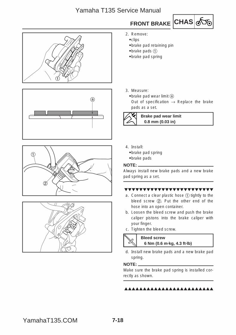
CHASFRONT BRAKE
7-18
1
a
1
2
2. Remove:9clips9brake pad retaining pin9brake pads 19brake pad spring
3. Measure:9brake pad wear limit aOut of specification → Replace the brakepads as a set.
4. Install:9brake pad spring9brake pads
NOTE:Always install new brake pads and a new brakepad spring as a set.
a. Connect a clear plastic hose 1 tightly to thebleed screw 2. Put the other end of thehose into an open container.
b. Loosen the bleed screw and push the brakecaliper pistons into the brake caliper withyour finger.
c. Tighten the bleed screw.
d. Install new brake pads and a new brake padspring.
NOTE:Make sure the brake pad spring is installed cor-rectly as shown.
Brake pad wear limit0.8 mm (0.03 in)
Bleed screw6 Nm (0.6 m·kg, 4.3 ft·lb)
5YP-F8197-E0_7_1 05.6.27 19:29 Page 18
Yamaha T135 Service Manual
YamahaT135.COM
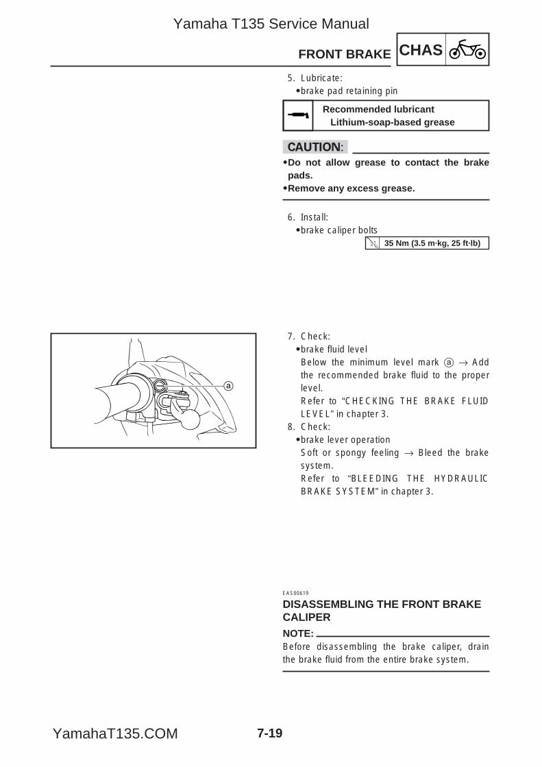
CHASFRONT BRAKE
7-19
a
5. Lubricate:9brake pad retaining pin
cC9Do not allow grease to contact the brakepads.9Remove any excess grease.
6. Install:9brake caliper bolts
7. Check:9brake fluid levelBelow the minimum level mark a → Addthe recommended brake fluid to the properlevel.Refer to “CHECKING THE BRAKE FLUIDLEVEL” in chapter 3.
8. Check:9brake lever operationSoft or spongy feeling → Bleed the brakesystem.Refer to “BLEEDING THE HYDRAULICBRAKE SYSTEM” in chapter 3.
EAS00619
DISASSEMBLING THE FRONT BRAKECALIPERNOTE:Before disassembling the brake caliper, drainthe brake fluid from the entire brake system.
Recommended lubricantLithium-soap-based grease
35 Nm (3.5 m·kg, 25 ft·lb)
5YP-F8197-E0_7_1 05.6.27 19:29 Page 19
Yamaha T135 Service Manual
YamahaT135.COM
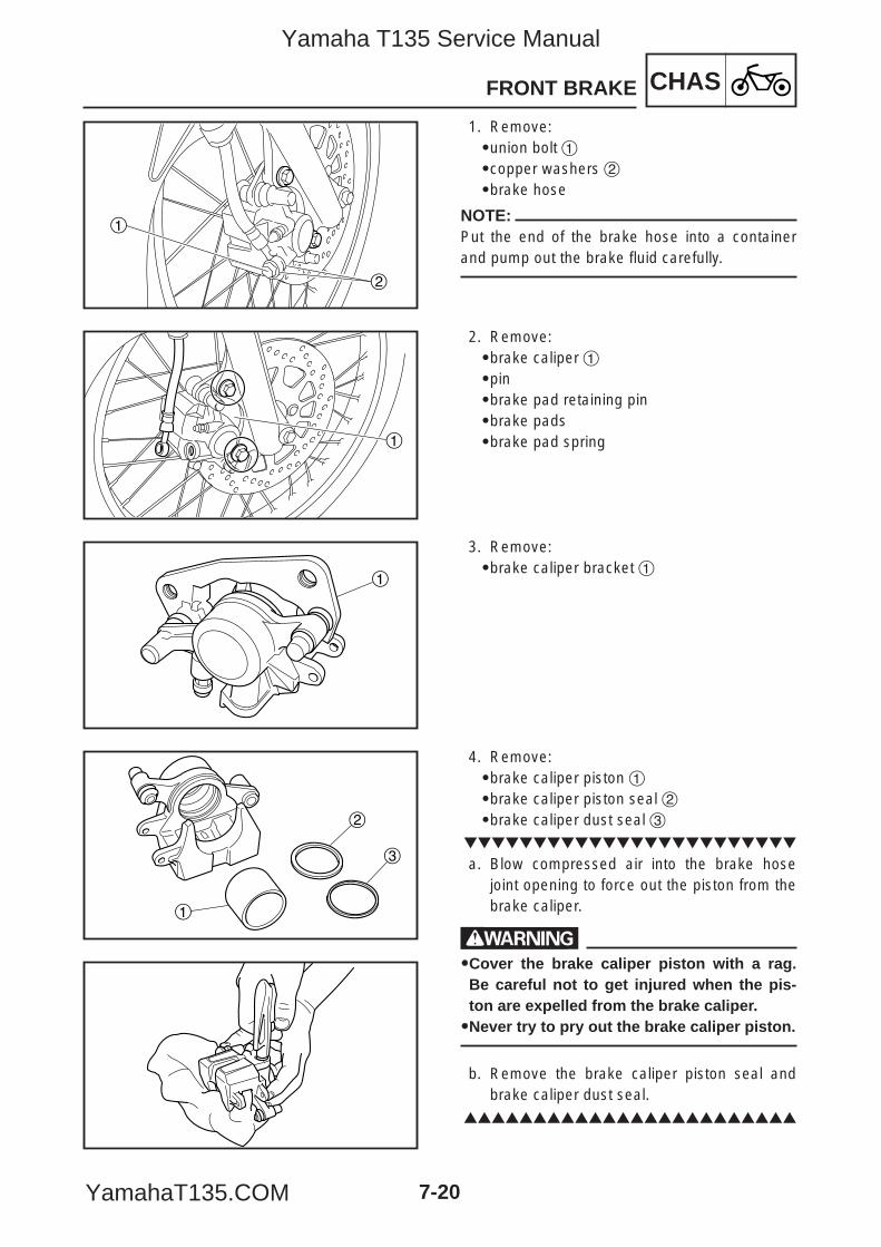
CHASFRONT BRAKE
7-20
1
2
1
1
2
3
1
1. Remove:9union bolt 19copper washers 29brake hose
NOTE:Put the end of the brake hose into a containerand pump out the brake fluid carefully.
2. Remove:9brake caliper 19pin9brake pad retaining pin9brake pads9brake pad spring
3. Remove:9brake caliper bracket 1
4. Remove:9brake caliper piston 19brake caliper piston seal 29brake caliper dust seal 3
a. Blow compressed air into the brake hosejoint opening to force out the piston from thebrake caliper.
w99Cover the brake caliper piston with a rag.Be careful not to get injured when the pis-ton are expelled from the brake caliper.99Never try to pry out the brake caliper piston.
b. Remove the brake caliper piston seal andbrake caliper dust seal.
5YP-F8197-E0_7_1 05.6.27 19:29 Page 20
Yamaha T135 Service Manual
YamahaT135.COM
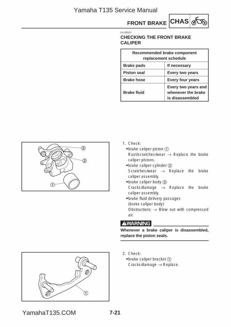
CHASFRONT BRAKE
7-21
1
2
3
1
EAS00631
CHECKING THE FRONT BRAKECALIPER
Recommended brake componentreplacement schedule
Brake pads If necessary
Piston seal Every two years
Brake hose Every four years
Every two years and Brake fluid whenever the brake
is disassembled
1. Check:9brake caliper piston 1Rust/scratches/wear → Replace the brakecaliper pistons.9brake caliper cylinder 2Scratches/wear → Replace the brakecaliper assembly.9brake caliper body 3Cracks/damage → Replace the brakecaliper assembly.9brake fluid delivery passages (brake caliper body)Obstructions → Blow out with compressedair.
wWhenever a brake caliper is disassembled,replace the piston seals.
2. Check:9brake caliper bracket 1Cracks/damage → Replace.
5YP-F8197-E0_7_1 05.6.27 19:29 Page 21
Yamaha T135 Service Manual
YamahaT135.COM
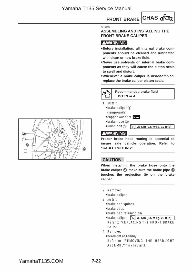
CHASFRONT BRAKE
7-22
3
2
ab
1
EAS00634
ASSEMBLING AND INSTALLING THEFRONT BRAKE CALIPER
w99Before installation, all internal brake com-ponents should be cleaned and lubricatedwith clean or new brake fluid.99Never use solvents on internal brake com-ponents as they will cause the piston sealsto swell and distort.99Whenever a brake caliper is disassembled,replace the brake caliper piston seals.
1. Install:9brake caliper 1(temporarily)9copper washers 9brake hose 29union bolt 3
wProper brake hose routing is essential toinsure safe vehicle operation. Refer to“CABLE ROUTING”.
cCWhen installing the brake hose onto thebrake caliper 11, make sure the brake pipe aatouches the projection bb on the brakecaliper.
2. Remove:9brake caliper
3. Install:9brake pad springs9brake pads9brake pad retaining pin9brake caliperRefer to “REPLACING THE FRONT BRAKEPADS”.
4. Remove:9headlight assemblyRefer to “REMOVING THE HEADLIGHTASSEMBLY” in chapter 3.
Recommended brake fluidDOT 3 or 4
26 Nm (2.6 m·kg, 19 ft·lb)
35 Nm (3.5 m·kg, 25 ft·lb)
5YP-F8197-E0_7_1 05.6.27 19:29 Page 22
Yamaha T135 Service Manual
YamahaT135.COM
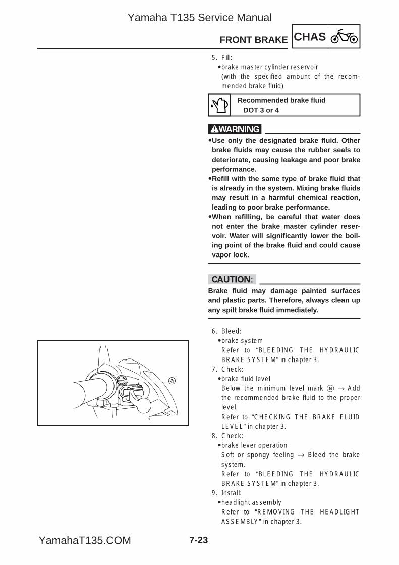
CHASFRONT BRAKE
7-23
a
5. Fill:9brake master cylinder reservoir(with the specified amount of the recom-mended brake fluid)
w99Use only the designated brake fluid. Otherbrake fluids may cause the rubber seals todeteriorate, causing leakage and poor brakeperformance.99Refill with the same type of brake fluid thatis already in the system. Mixing brake fluidsmay result in a harmful chemical reaction,leading to poor brake performance.99When refilling, be careful that water doesnot enter the brake master cylinder reser-voir. Water will significantly lower the boil-ing point of the brake fluid and could causevapor lock.
cCBrake fluid may damage painted surfacesand plastic parts. Therefore, always clean upany spilt brake fluid immediately.
6. Bleed:9brake systemRefer to “BLEEDING THE HYDRAULICBRAKE SYSTEM” in chapter 3.
7. Check:9brake fluid levelBelow the minimum level mark a → Addthe recommended brake fluid to the properlevel.Refer to “CHECKING THE BRAKE FLUIDLEVEL” in chapter 3.
8. Check:9brake lever operationSoft or spongy feeling → Bleed the brakesystem.Refer to “BLEEDING THE HYDRAULICBRAKE SYSTEM” in chapter 3.
9. Install:9headlight assemblyRefer to “REMOVING THE HEADLIGHTASSEMBLY” in chapter 3.
Recommended brake fluidDOT 3 or 4
5YP-F8197-E0_7_1 05.6.27 19:29 Page 23
Yamaha T135 Service Manual
YamahaT135.COM
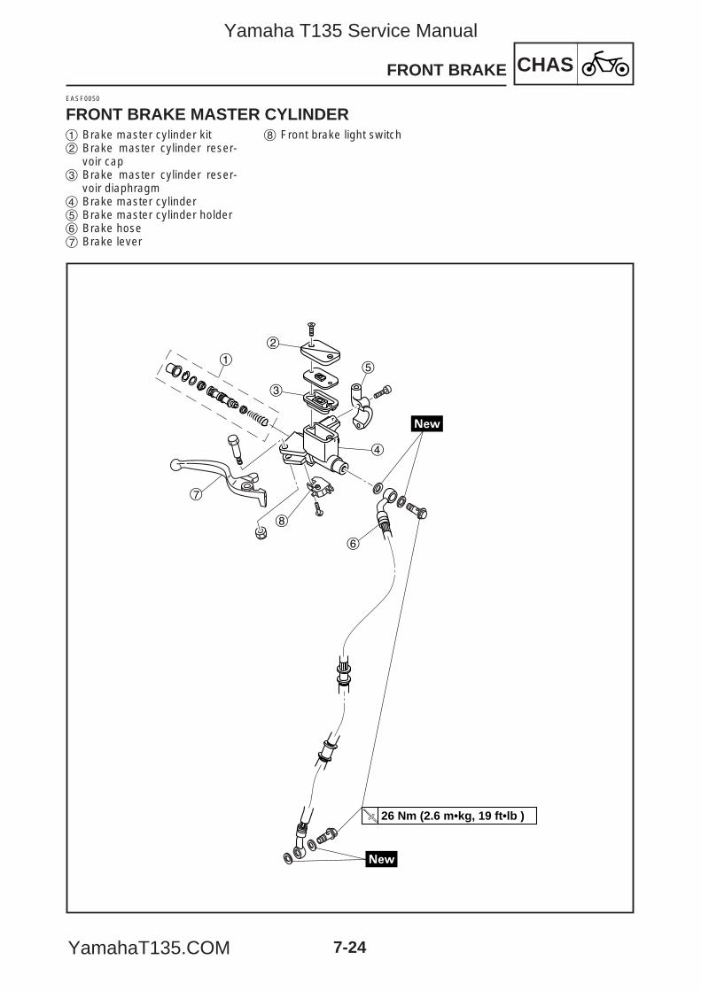
CHAS
7-24
FRONT BRAKE
EASF0050
FRONT BRAKE MASTER CYLINDER
26 Nm (2.6 m•kg, 19 ft•lb )
1
2
3
5
4
6
8
7
1 Brake master cylinder kit2 Brake master cylinder reser-
voir cap3 Brake master cylinder reser-
voir diaphragm4 Brake master cylinder5 Brake master cylinder holder6 Brake hose7 Brake lever
8 Front brake light switch
5YP-F8197-E0_7_1 05.6.27 19:29 Page 24
Yamaha T135 Service Manual
YamahaT135.COM
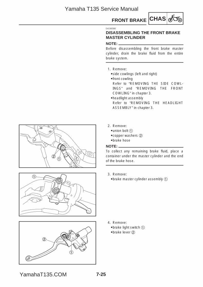
CHASFRONT BRAKE
7-25
12
1
2
1
EAS00588
DISASSEMBLING THE FRONT BRAKEMASTER CYLINDERNOTE:Before disassembling the front brake mastercylinder, drain the brake fluid from the entirebrake system.
1. Remove:9side cowlings (left and right)9front cowling Refer to “REMOVING THE SIDE COWL-INGS” and “REMOVING THE FRONTCOWLING” in chapter 3.9headlight assemblyRefer to “REMOVING THE HEADLIGHTASSEMBLY” in chapter 3.
2. Remove:9union bolt 19copper washers 29brake hose
NOTE:To collect any remaining brake fluid, place acontainer under the master cylinder and the endof the brake hose.
3. Remove:9brake master cylinder assembly 1
4. Remove:9brake light switch 19brake lever 2
5YP-F8197-E0_7_1 05.6.27 19:29 Page 25
Yamaha T135 Service Manual
YamahaT135.COM
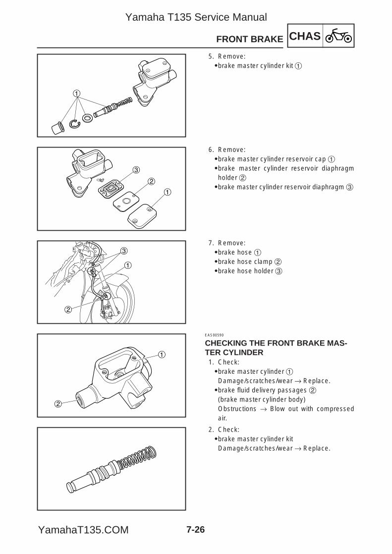
CHASFRONT BRAKE
7-26
1
1
2
3
2
1
3
1
2
5. Remove:9brake master cylinder kit 1
6. Remove:9brake master cylinder reservoir cap 19brake master cylinder reservoir diaphragmholder 29brake master cylinder reservoir diaphragm 3
7. Remove:9brake hose 19brake hose clamp 29brake hose holder 3
EAS00590
CHECKING THE FRONT BRAKE MAS-TER CYLINDER1. Check:9brake master cylinder 1Damage/scratches/wear → Replace.9brake fluid delivery passages 2(brake master cylinder body)Obstructions → Blow out with compressedair.
2. Check:9brake master cylinder kitDamage/scratches/wear → Replace.
5YP-F8197-E0_7_1 05.6.27 19:29 Page 26
Yamaha T135 Service Manual
YamahaT135.COM
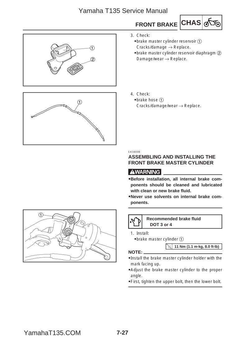
CHASFRONT BRAKE
7-27
1
2
1
1
3. Check:9brake master cylinder reservoir 1Cracks/damage → Replace.9brake master cylinder reservoir diaphragm 2Damage/wear → Replace.
4. Check:9brake hose 1Cracks/damage/wear → Replace.
EAS00598
ASSEMBLING AND INSTALLING THEFRONT BRAKE MASTER CYLINDER
w99Before installation, all internal brake com-ponents should be cleaned and lubricatedwith clean or new brake fluid.99Never use solvents on internal brake com-ponents.
1. Install:9brake master cylinder 1
NOTE:9Install the brake master cylinder holder with themark facing up.9Adjust the brake master cylinder to the properangle.9First, tighten the upper bolt, then the lower bolt.
Recommended brake fluidDOT 3 or 4
11 Nm (1.1 m·kg, 8.0 ft·lb)
5YP-F8197-E0_7_1 05.6.27 19:29 Page 27
Yamaha T135 Service Manual
YamahaT135.COM
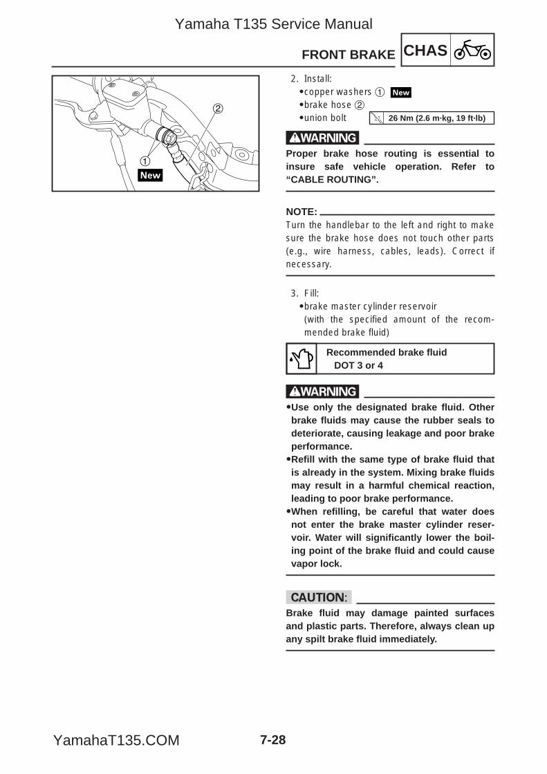
CHASFRONT BRAKE
7-28
1
2
2. Install:9copper washers 1
9brake hose 29union bolt
wProper brake hose routing is essential toinsure safe vehicle operation. Refer to“CABLE ROUTING”.
NOTE:Turn the handlebar to the left and right to makesure the brake hose does not touch other parts(e.g., wire harness, cables, leads). Correct ifnecessary.
3. Fill:9brake master cylinder reservoir(with the specified amount of the recom-mended brake fluid)
w99Use only the designated brake fluid. Otherbrake fluids may cause the rubber seals todeteriorate, causing leakage and poor brakeperformance.99Refill with the same type of brake fluid thatis already in the system. Mixing brake fluidsmay result in a harmful chemical reaction,leading to poor brake performance.99When refilling, be careful that water doesnot enter the brake master cylinder reser-voir. Water will significantly lower the boil-ing point of the brake fluid and could causevapor lock.
cCBrake fluid may damage painted surfacesand plastic parts. Therefore, always clean upany spilt brake fluid immediately.
Recommended brake fluidDOT 3 or 4
26 Nm (2.6 m·kg, 19 ft·lb)
5YP-F8197-E0_7_1 05.6.27 19:29 Page 28
Yamaha T135 Service Manual
YamahaT135.COM
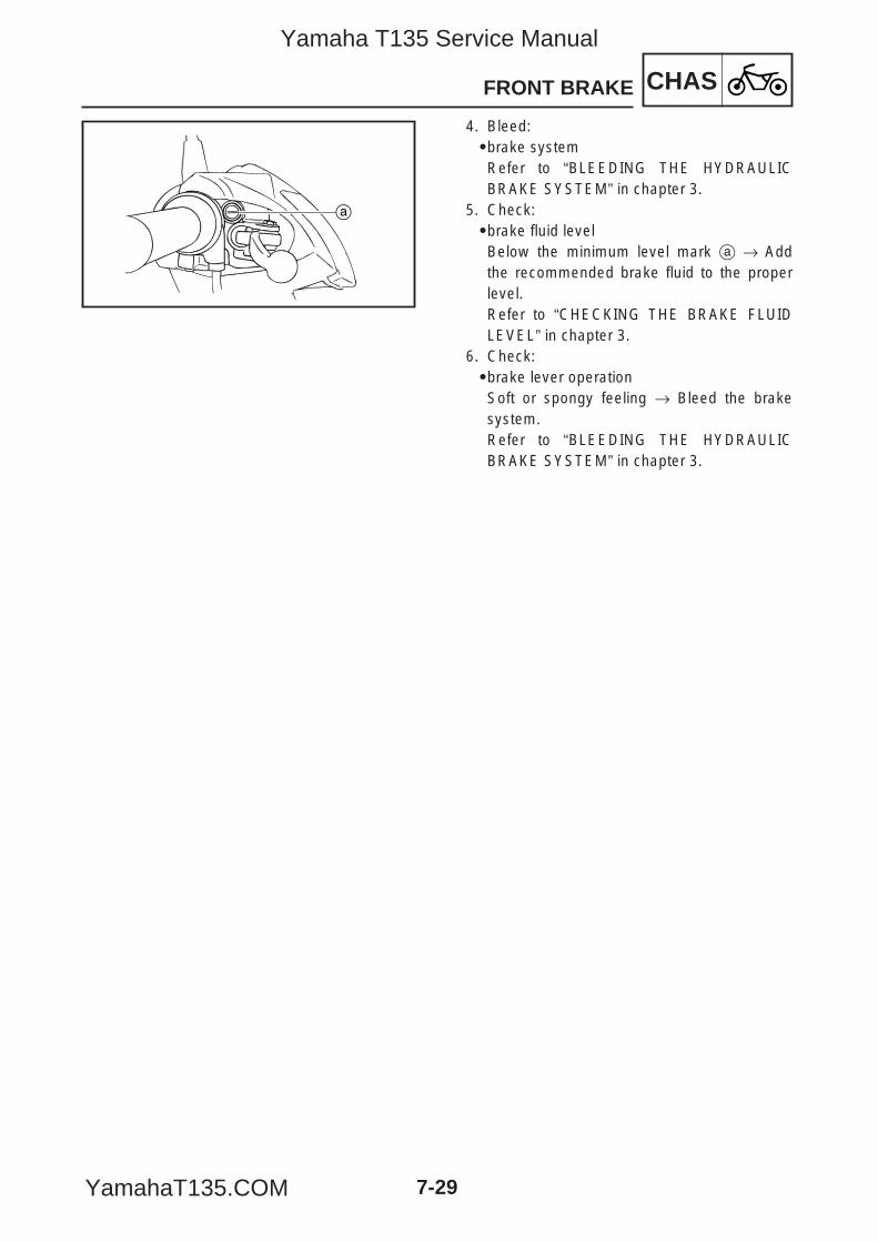
CHASFRONT BRAKE
7-29
a
4. Bleed:9brake systemRefer to “BLEEDING THE HYDRAULICBRAKE SYSTEM” in chapter 3.
5. Check:9brake fluid levelBelow the minimum level mark a → Addthe recommended brake fluid to the properlevel.Refer to “CHECKING THE BRAKE FLUIDLEVEL” in chapter 3.
6. Check:9brake lever operationSoft or spongy feeling → Bleed the brakesystem.Refer to “BLEEDING THE HYDRAULICBRAKE SYSTEM” in chapter 3.
5YP-F8197-E0_7_1 05.6.27 19:29 Page 29
Yamaha T135 Service Manual
YamahaT135.COM

7-30
CHASFRONT FORK
EASF0054
FRONT FORK
23 Nm (2.3 m•kg, 17 ft•lb )
143 Nm (4.3 m•kg, 31 ft•lb )
5
6
9
8
4
3
2
7
1 Front fork cap bolt 2 Dust seal 3 Oil seal clip4 Oil seal5 Fork spring6 Damper rod7 Inner tube8 Outer tube9 Damper rod bolt
5YP-F8197-E0_7_1 05.6.27 19:29 Page 30
Yamaha T135 Service Manual
YamahaT135.COM
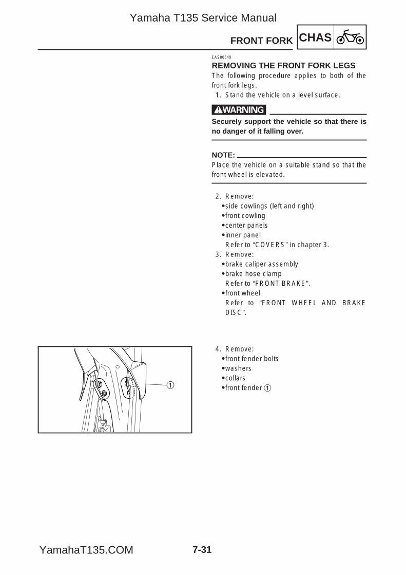
CHASFRONT FORK
7-31
1
EAS00649
REMOVING THE FRONT FORK LEGSThe following procedure applies to both of thefront fork legs.1. Stand the vehicle on a level surface.
wSecurely support the vehicle so that there isno danger of it falling over.
NOTE:Place the vehicle on a suitable stand so that thefront wheel is elevated.
2. Remove:9side cowlings (left and right)9front cowling9center panels9inner panelRefer to “COVERS” in chapter 3.
3. Remove:9brake caliper assembly9brake hose clampRefer to “FRONT BRAKE”.9front wheelRefer to “FRONT WHEEL AND BRAKEDISC”.
4. Remove:9front fender bolts9washers9collars9front fender 1
5YP-F8197-E0_7_1 05.6.27 19:29 Page 31
Yamaha T135 Service Manual
YamahaT135.COM
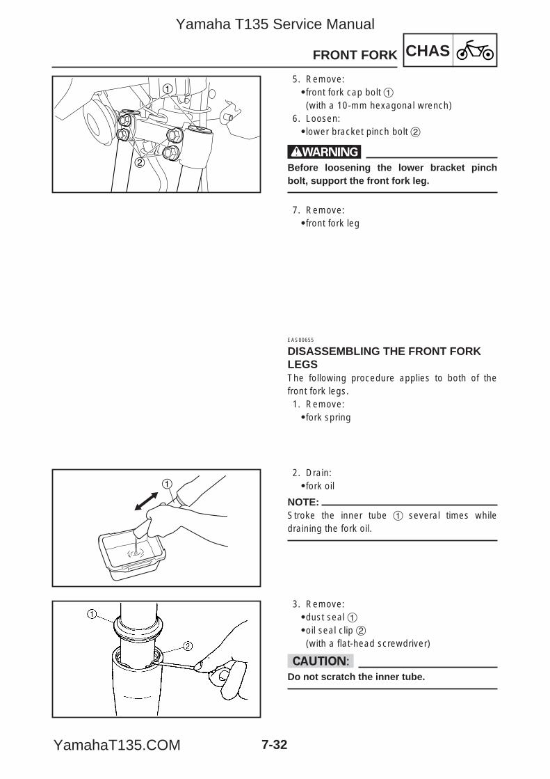
CHASFRONT FORK
7-32
2
1
1
5. Remove:9front fork cap bolt 1(with a 10-mm hexagonal wrench)
6. Loosen:9lower bracket pinch bolt 2
wBefore loosening the lower bracket pinchbolt, support the front fork leg.
7. Remove:9front fork leg
EAS00655
DISASSEMBLING THE FRONT FORKLEGSThe following procedure applies to both of thefront fork legs.1. Remove:9fork spring
2. Drain:9fork oil
NOTE:Stroke the inner tube 1 several times whiledraining the fork oil.
3. Remove:9dust seal 19oil seal clip 2(with a flat-head screwdriver)
cCDo not scratch the inner tube.
5YP-F8197-E0_7_1 05.6.27 19:29 Page 32
Yamaha T135 Service Manual
YamahaT135.COM

CHASFRONT FORK
7-33
4. Remove:9damper rod assembly bolt9copper washer
NOTE:While holding the damper rod assembly with a10 mm hexagon nut/socket wrench 1 and the T-handle 2, loosen the damper rod assembly bolt3.
5. Remove:9inner tube9rebound spring9damper rod
NOTE:Pull out the inner tube and damper rod together.
6. Remove:9oil seal 1
2 Rag
T-handle90890-01326
5YP-F8197-E0_7_1 05.6.27 19:29 Page 33
Yamaha T135 Service Manual
YamahaT135.COM
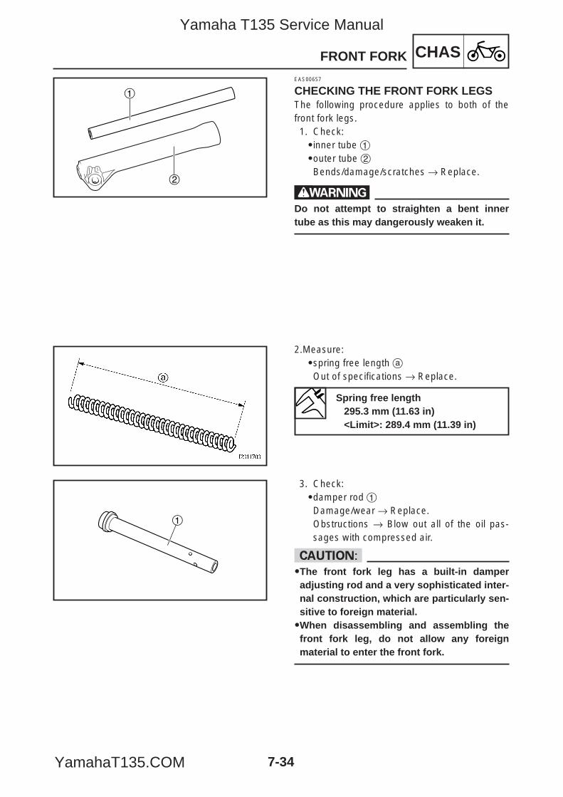
CHASFRONT FORK
7-34
1
2
1
EAS00657
CHECKING THE FRONT FORK LEGSThe following procedure applies to both of thefront fork legs.1. Check:9inner tube 19outer tube 2Bends/damage/scratches → Replace.
wDo not attempt to straighten a bent innertube as this may dangerously weaken it.
2.Measure:9spring free length aOut of specifications → Replace.
3. Check:9damper rod 1Damage/wear → Replace.Obstructions → Blow out all of the oil pas-sages with compressed air.
cC99The front fork leg has a built-in damperadjusting rod and a very sophisticated inter-nal construction, which are particularly sen-sitive to foreign material.99When disassembling and assembling thefront fork leg, do not allow any foreignmaterial to enter the front fork.
Spring free length295.3 mm (11.63 in)<Limit>: 289.4 mm (11.39 in)
5YP-F8197-E0_7_1 05.6.27 19:29 Page 34
Yamaha T135 Service Manual
YamahaT135.COM
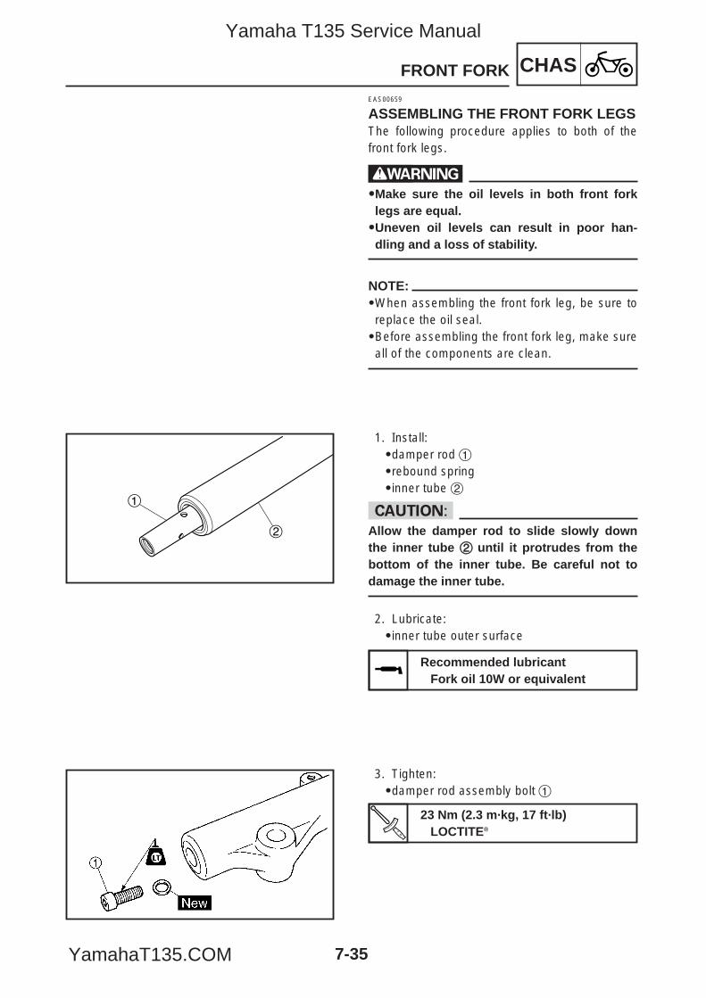
CHASFRONT FORK
7-35
1
2
EAS00659
ASSEMBLING THE FRONT FORK LEGSThe following procedure applies to both of thefront fork legs.
w99Make sure the oil levels in both front forklegs are equal.99Uneven oil levels can result in poor han-dling and a loss of stability.
NOTE:9When assembling the front fork leg, be sure toreplace the oil seal.9Before assembling the front fork leg, make sureall of the components are clean.
1. Install:9damper rod 19rebound spring 9inner tube 2
cCAllow the damper rod to slide slowly downthe inner tube 22 until it protrudes from thebottom of the inner tube. Be careful not todamage the inner tube.
2. Lubricate:9inner tube outer surface
3. Tighten:9damper rod assembly bolt 1
Recommended lubricantFork oil 10W or equivalent
23 Nm (2.3 m·kg, 17 ft·lb)LOCTITE®
5YP-F8197-E0_7_1 05.6.27 19:29 Page 35
Yamaha T135 Service Manual
YamahaT135.COM
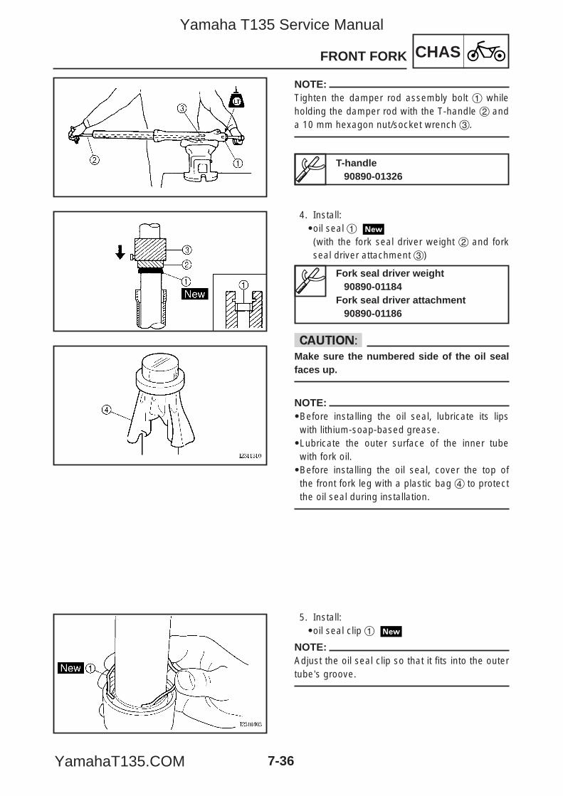
CHASFRONT FORK
7-36
NOTE:Tighten the damper rod assembly bolt 1 whileholding the damper rod with the T-handle 2 anda 10 mm hexagon nut/socket wrench 3.
4. Install:9oil seal 1
(with the fork seal driver weight 2 and forkseal driver attachment 3)
cCMake sure the numbered side of the oil sealfaces up.
NOTE:9Before installing the oil seal, lubricate its lipswith lithium-soap-based grease.9Lubricate the outer surface of the inner tubewith fork oil.9Before installing the oil seal, cover the top ofthe front fork leg with a plastic bag 4 to protectthe oil seal during installation.
5. Install:9oil seal clip 1
NOTE:Adjust the oil seal clip so that it fits into the outertube’s groove.
T-handle90890-01326
Fork seal driver weight90890-01184
Fork seal driver attachment90890-01186
5YP-F8197-E0_7_1 05.6.27 19:29 Page 36
Yamaha T135 Service Manual
YamahaT135.COM
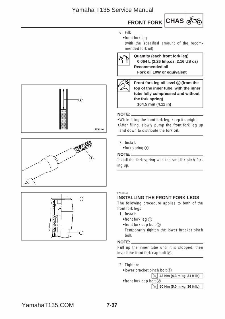
CHASFRONT FORK
7-37
6. Fill:9front fork leg(with the specified amount of the recom-mended fork oil)
NOTE:9While filling the front fork leg, keep it upright.9After filling, slowly pump the front fork leg upand down to distribute the fork oil.
7. Install:9fork spring 1
NOTE:Install the fork spring with the smaller pitch fac-ing up.
EAS00662
INSTALLING THE FRONT FORK LEGSThe following procedure applies to both of thefront fork legs.1. Install:9front fork leg 19front fork cap bolt 2Temporarily tighten the lower bracket pinchbolt.
NOTE:Pull up the inner tube until it is stopped, theninstall the front fork cap bolt 2.
2. Tighten:9lower bracket pinch bolt 1
9front fork cap bolt 2
Quantity (each front fork leg)0.064 L (2.26 Imp.oz, 2.16 US oz)
Recommended oilFork oil 10W or equivalent
Front fork leg oil level aa (from thetop of the inner tube, with the innertube fully compressed and withoutthe fork spring)
104.5 mm (4.11 in)
43 Nm (4.3 m·kg, 31 ft·lb)
50 Nm (5.0 m·kg, 36 ft·lb)
5YP-F8197-E0_7_1 05.6.27 19:30 Page 37
Yamaha T135 Service Manual
YamahaT135.COM
CHASFRONT FORK
7-38
3. Install:9front fender
4. Install:9front wheelRefer to “FRONT WHEEL AND BRAKEDISC”.9brake hose clamp9brake caliper assemblyRefer to “FRONT BRAKE”.
10 Nm (1.0 m·kg, 7.2 ft·lb)
5YP-F8197-E0_7_1 05.6.27 19:30 Page 38
Yamaha T135 Service Manual
YamahaT135.COM
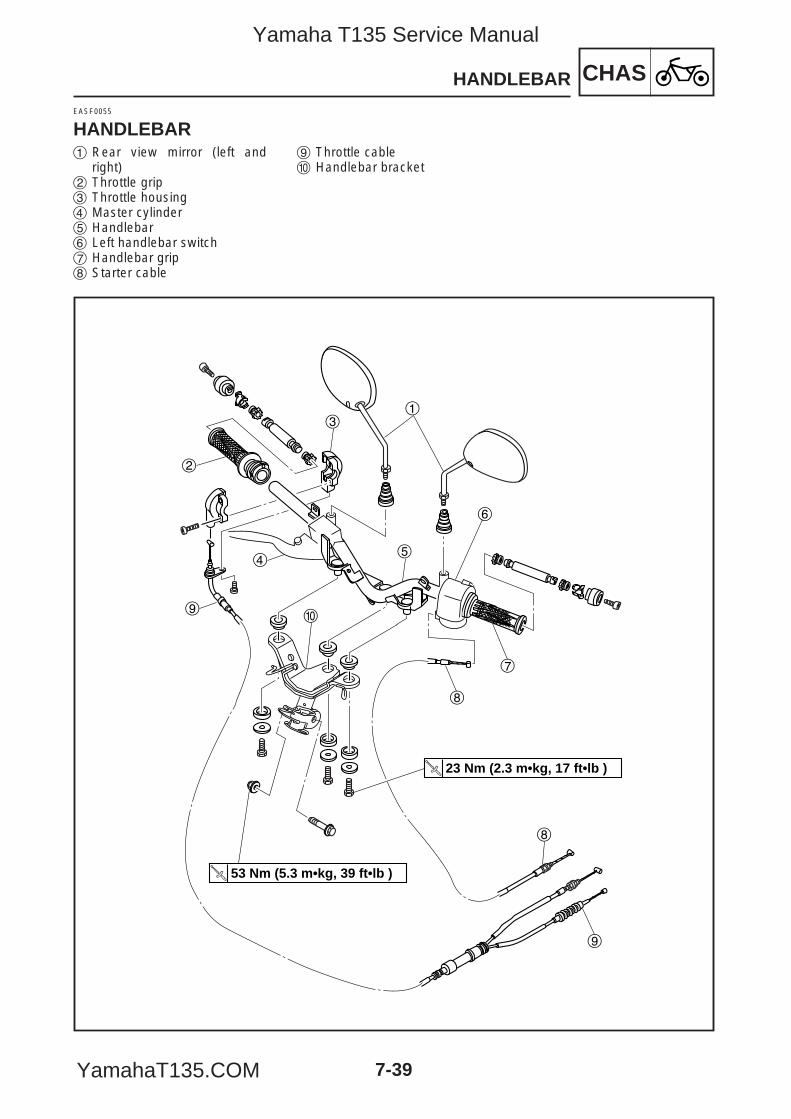
7-39
CHASHANDLEBAR
EASF0055
HANDLEBAR
53 Nm (5.3 m•kg, 39 ft•lb )
23 Nm (2.3 m•kg, 17 ft•lb )
1
2
3
45
6
7
8
8
90
9
1 Rear view mirror (left andright)
2 Throttle grip3 Throttle housing4 Master cylinder5 Handlebar6 Left handlebar switch7 Handlebar grip8 Starter cable
9 Throttle cable0 Handlebar bracket
5YP-F8197-E0_7_1 05.6.27 19:30 Page 39
Yamaha T135 Service Manual
YamahaT135.COM
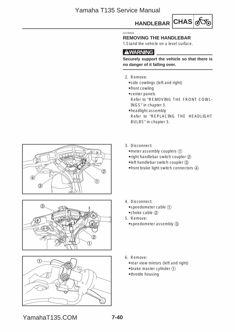
CHASHANDLEBAR
7-40
2
31
4
1
2
3
1
EAS00666
REMOVING THE HANDLEBAR1.Stand the vehicle on a level surface.
wSecurely support the vehicle so that there isno danger of it falling over.
2. Remove:9side cowlings (left and right)9front cowling9center panelsRefer to “REMOVING THE FRONT COWL-INGS” in chapter 3.9headlight assemblyRefer to “REPLACING THE HEADLIGHTBULBS” in chapter 3.
3. Disconnect:9meter assembly couplers 19right handlebar switch coupler 29left handlebar switch coupler 39front brake light switch connectors 4
4. Disconnect:9speedometer cable 19choke cable 2
5. Remove:9speedometer assembly 3
6. Remove:9rear view mirrors (left and right) 9brake master cylinder 19throttle housing
5YP-F8197-E0_7_1 05.6.27 19:30 Page 40
Yamaha T135 Service Manual
YamahaT135.COM
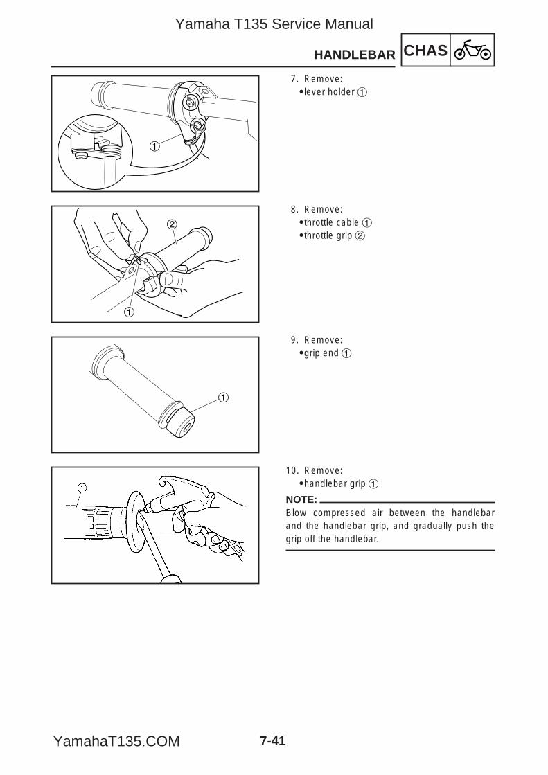
CHASHANDLEBAR
7-41
1
2
1
1
7. Remove:9lever holder 1
8. Remove:9throttle cable 19throttle grip 2
9. Remove:9grip end 1
10. Remove:9handlebar grip 1
NOTE:Blow compressed air between the handlebarand the handlebar grip, and gradually push thegrip off the handlebar.
5YP-F8197-E0_7_1 05.6.27 19:30 Page 41
Yamaha T135 Service Manual
YamahaT135.COM
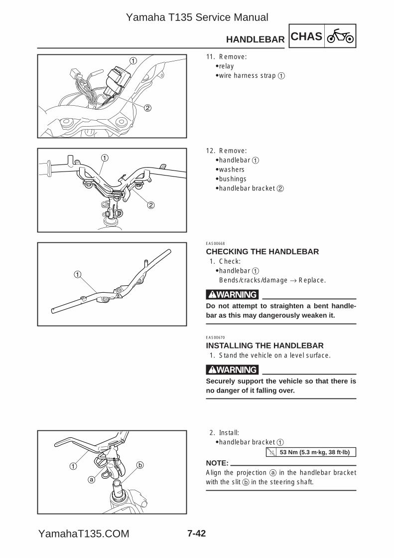
CHASHANDLEBAR
7-42
1
2
1
2
1
1
a
b
11. Remove:9relay9wire harness strap 1
12. Remove:9handlebar 19washers9bushings9handlebar bracket 2
EAS00668
CHECKING THE HANDLEBAR1. Check:9handlebar 1Bends/cracks/damage → Replace.
wDo not attempt to straighten a bent handle-bar as this may dangerously weaken it.
EAS00670
INSTALLING THE HANDLEBAR1. Stand the vehicle on a level surface.
wSecurely support the vehicle so that there isno danger of it falling over.
2. Install:9handlebar bracket 1
NOTE:Align the projection a in the handlebar bracketwith the slit b in the steering shaft.
53 Nm (5.3 m·kg, 38 ft·lb)
5YP-F8197-E0_7_1 05.6.27 19:30 Page 42
Yamaha T135 Service Manual
YamahaT135.COM
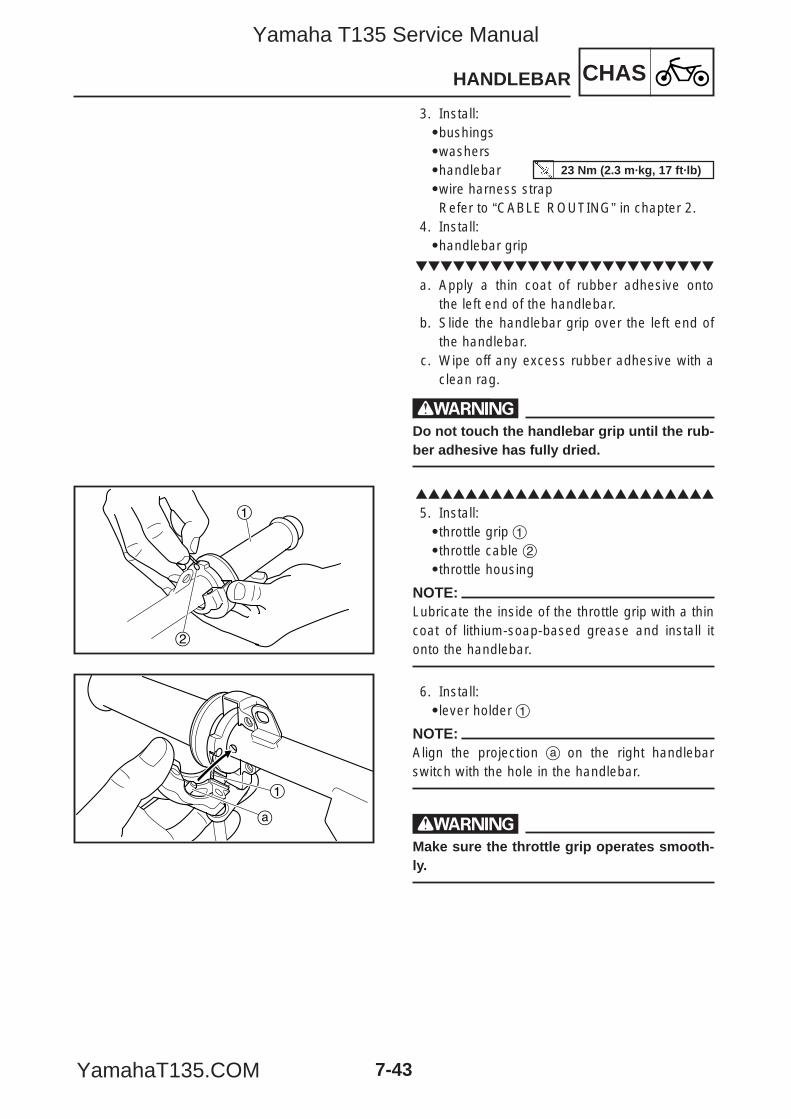
CHASHANDLEBAR
7-43
a
1
1
2
3. Install:9bushings9washers9handlebar9wire harness strapRefer to “CABLE ROUTING” in chapter 2.
4. Install:9handlebar grip
a. Apply a thin coat of rubber adhesive ontothe left end of the handlebar.
b. Slide the handlebar grip over the left end ofthe handlebar.
c. Wipe off any excess rubber adhesive with aclean rag.
wDo not touch the handlebar grip until the rub-ber adhesive has fully dried.
5. Install:9throttle grip 19throttle cable 29throttle housing
NOTE:Lubricate the inside of the throttle grip with a thincoat of lithium-soap-based grease and install itonto the handlebar.
6. Install:9lever holder 1
NOTE:Align the projection a on the right handlebarswitch with the hole in the handlebar.
wMake sure the throttle grip operates smooth-ly.
23 Nm (2.3 m·kg, 17 ft·lb)
5YP-F8197-E0_7_1 05.6.27 19:30 Page 43
Yamaha T135 Service Manual
YamahaT135.COM
CHASHANDLEBAR
7-44
7. Install:9brake master cylinder
Refer to “FRONT BRAKE”.8. Install:9plastic locking tiesRefer to “CABLE ROUTING” in chapter 2.
9. Adjust:9throttle cable free playRefer to “ADJUSTING THE THROTTLECABLE FREE PLAY” in chapter 3.
Throttle cable free play (at theflange of the throttle grip)
3–7 mm (0.12–0.28 in)
11 Nm (1.1 m·kg, 8.0 ft·lb)
5YP-F8197-E0_7_1 05.6.27 19:30 Page 44
Yamaha T135 Service Manual
YamahaT135.COM
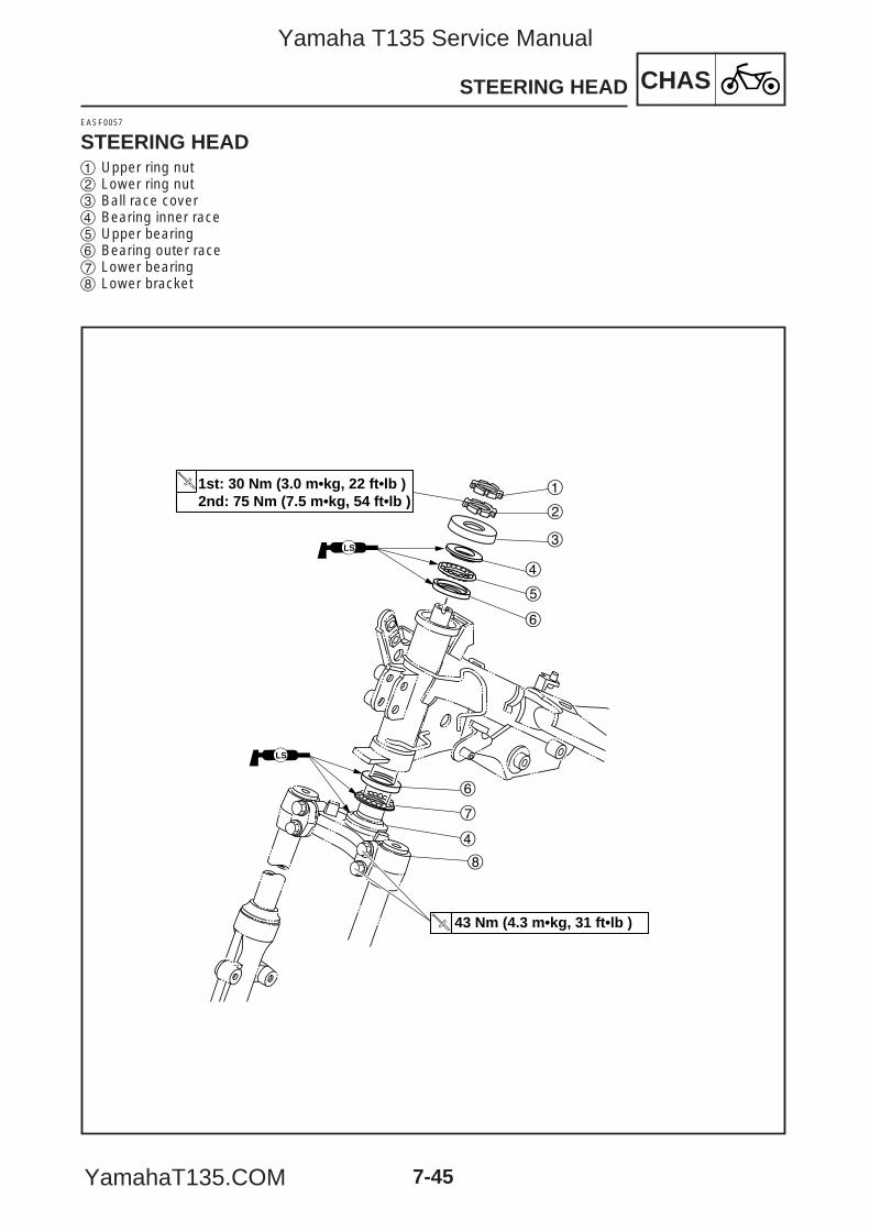
STEERING HEAD CHAS
7-45
EASF0057
STEERING HEAD
1st: 30 Nm (3.0 m•kg, 22 ft•lb )2nd: 75 Nm (7.5 m•kg, 54 ft•lb )
LS
1
43 Nm (4.3 m•kg, 31 ft•lb )
LS
2
3
4
5
6
6
7
4
8
1 Upper ring nut2 Lower ring nut3 Ball race cover4 Bearing inner race5 Upper bearing6 Bearing outer race7 Lower bearing8 Lower bracket
5YP-F8197-E0_7_1 05.6.27 19:30 Page 45
Yamaha T135 Service Manual
YamahaT135.COM
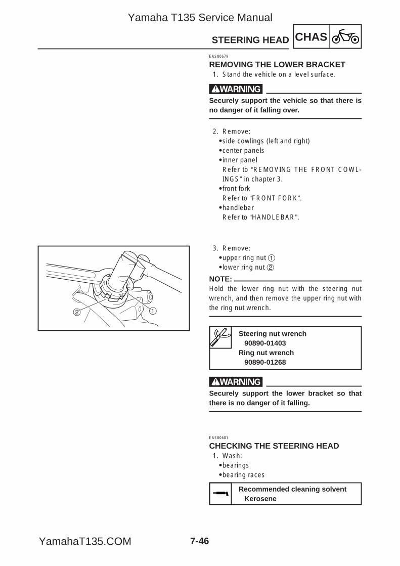
CHASSTEERING HEAD
7-46
2 1
EAS00679
REMOVING THE LOWER BRACKET1. Stand the vehicle on a level surface.
wSecurely support the vehicle so that there isno danger of it falling over.
2. Remove:9side cowlings (left and right)9center panels9inner panelRefer to “REMOVING THE FRONT COWL-INGS” in chapter 3.9front forkRefer to “FRONT FORK”.9handlebarRefer to “HANDLEBAR”.
3. Remove:9upper ring nut 19lower ring nut 2
NOTE:Hold the lower ring nut with the steering nutwrench, and then remove the upper ring nut withthe ring nut wrench.
wSecurely support the lower bracket so thatthere is no danger of it falling.
EAS00681
CHECKING THE STEERING HEAD1. Wash:9bearings9bearing races
Steering nut wrench90890-01403
Ring nut wrench90890-01268
Recommended cleaning solventKerosene
5YP-F8197-E0_7_1 05.6.27 19:30 Page 46
Yamaha T135 Service Manual
YamahaT135.COM
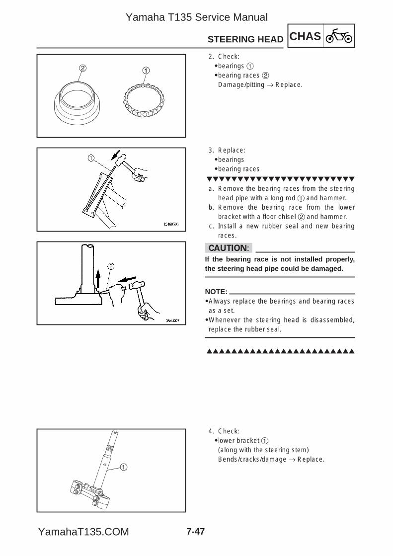
CHASSTEERING HEAD
7-47
2 1
1
2. Check:9bearings 19bearing races 2Damage/pitting → Replace.
3. Replace:9bearings9bearing races
a. Remove the bearing races from the steeringhead pipe with a long rod 1 and hammer.
b. Remove the bearing race from the lowerbracket with a floor chisel 2 and hammer.
c. Install a new rubber seal and new bearingraces.
cCIf the bearing race is not installed properly,the steering head pipe could be damaged.
NOTE:9Always replace the bearings and bearing racesas a set.9Whenever the steering head is disassembled,replace the rubber seal.
4. Check:9lower bracket 1(along with the steering stem)Bends/cracks/damage → Replace.
5YP-F8197-E0_7_1 05.6.27 19:30 Page 47
Yamaha T135 Service Manual
YamahaT135.COM
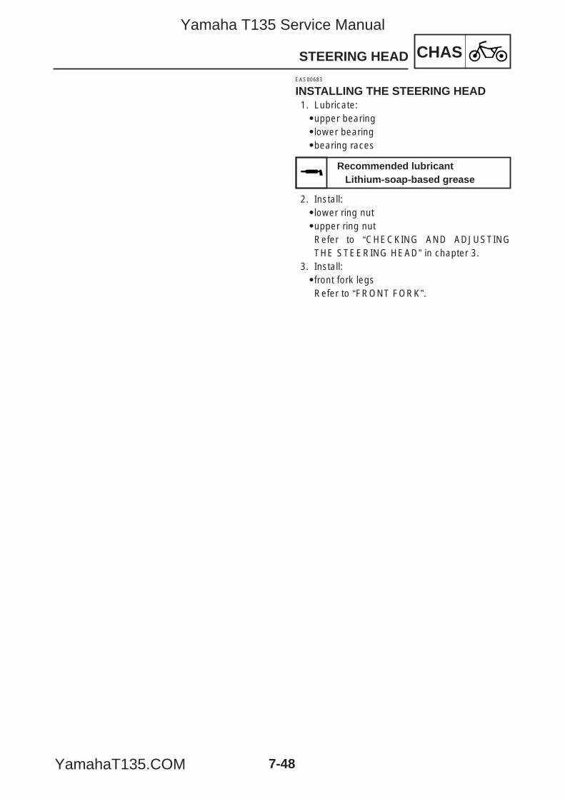
CHASSTEERING HEAD
7-48
EAS00683
INSTALLING THE STEERING HEAD1. Lubricate:9upper bearing9lower bearing9bearing races
2. Install:9lower ring nut9upper ring nutRefer to “CHECKING AND ADJUSTINGTHE STEERING HEAD” in chapter 3.
3. Install:9front fork legsRefer to “FRONT FORK”.
Recommended lubricantLithium-soap-based grease
5YP-F8197-E0_7_1 05.6.27 19:30 Page 48
Yamaha T135 Service Manual
YamahaT135.COM
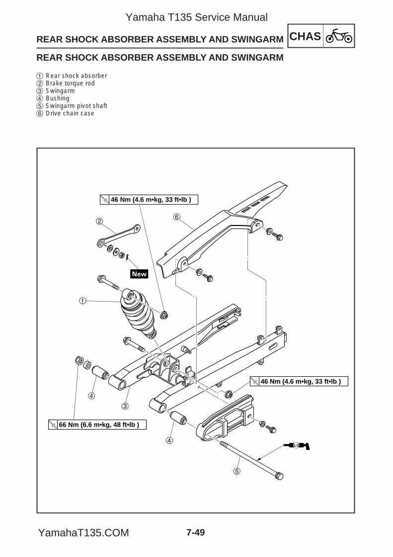
REAR SHOCK ABSORBER ASSEMBLY AND SWINGARM CHAS
7-49
REAR SHOCK ABSORBER ASSEMBLY AND SWINGARM
46 Nm (4.6 m•kg, 33 ft•lb )
LS
46 Nm (4.6 m•kg, 33 ft•lb )
66 Nm (6.6 m•kg, 48 ft•lb )
1
2
3
4
4
5
6
1 Rear shock absorber2 Brake torque rod3 Swingarm4 Bushing5 Swingarm pivot shaft6 Drive chain case
5YP-F8197-E0_7_1 05.6.27 19:30 Page 49
Yamaha T135 Service Manual
YamahaT135.COM
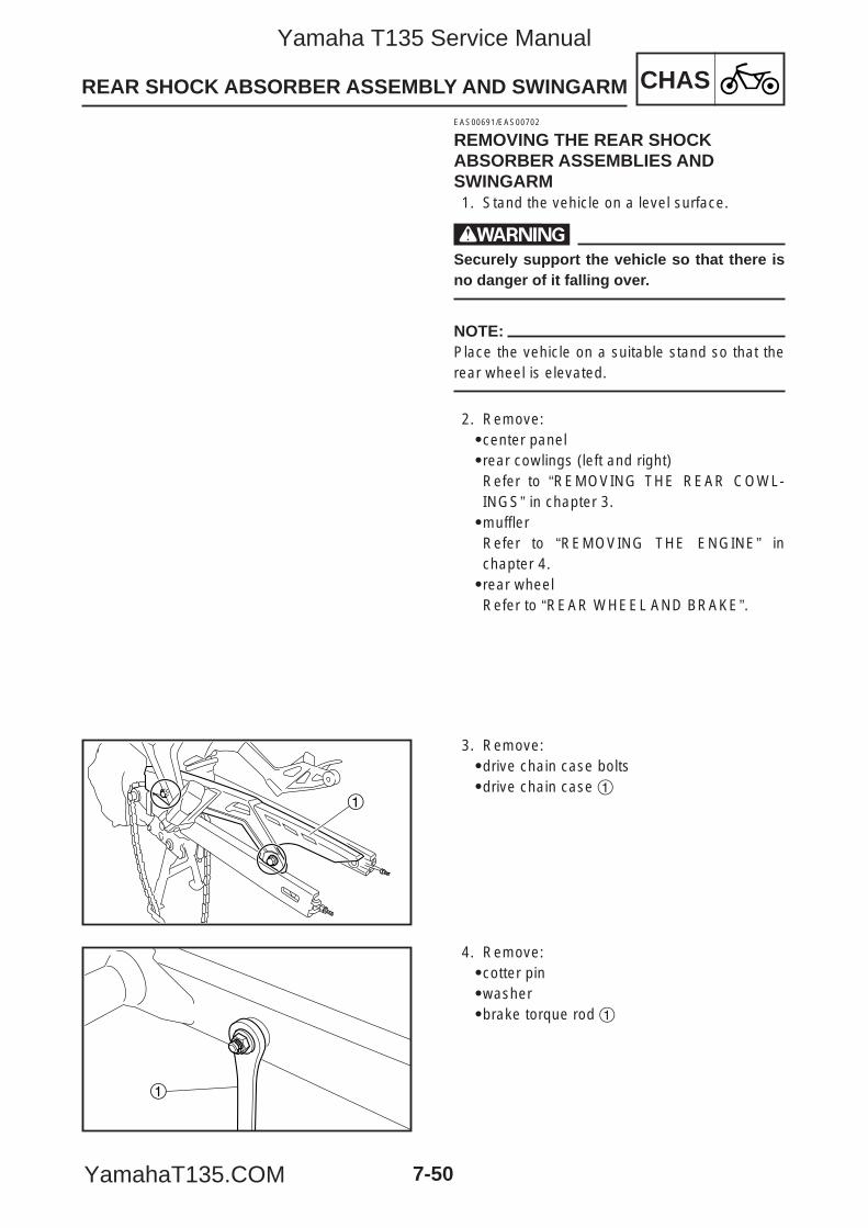
CHASREAR SHOCK ABSORBER ASSEMBLY AND SWINGARM
7-50
EAS00691/EAS00702
REMOVING THE REAR SHOCKABSORBER ASSEMBLIES ANDSWINGARM1. Stand the vehicle on a level surface.
wSecurely support the vehicle so that there isno danger of it falling over.
NOTE:Place the vehicle on a suitable stand so that therear wheel is elevated.
2. Remove:9center panel9rear cowlings (left and right)Refer to “REMOVING THE REAR COWL-INGS” in chapter 3.9mufflerRefer to “REMOVING THE ENGINE” inchapter 4.9rear wheelRefer to “REAR WHEEL AND BRAKE”.
1
3. Remove:9drive chain case bolts9drive chain case 1
1
4. Remove:9cotter pin9washer9brake torque rod 1
5YP-F8197-E0_7_1 05.6.27 19:30 Page 50
Yamaha T135 Service Manual
YamahaT135.COM
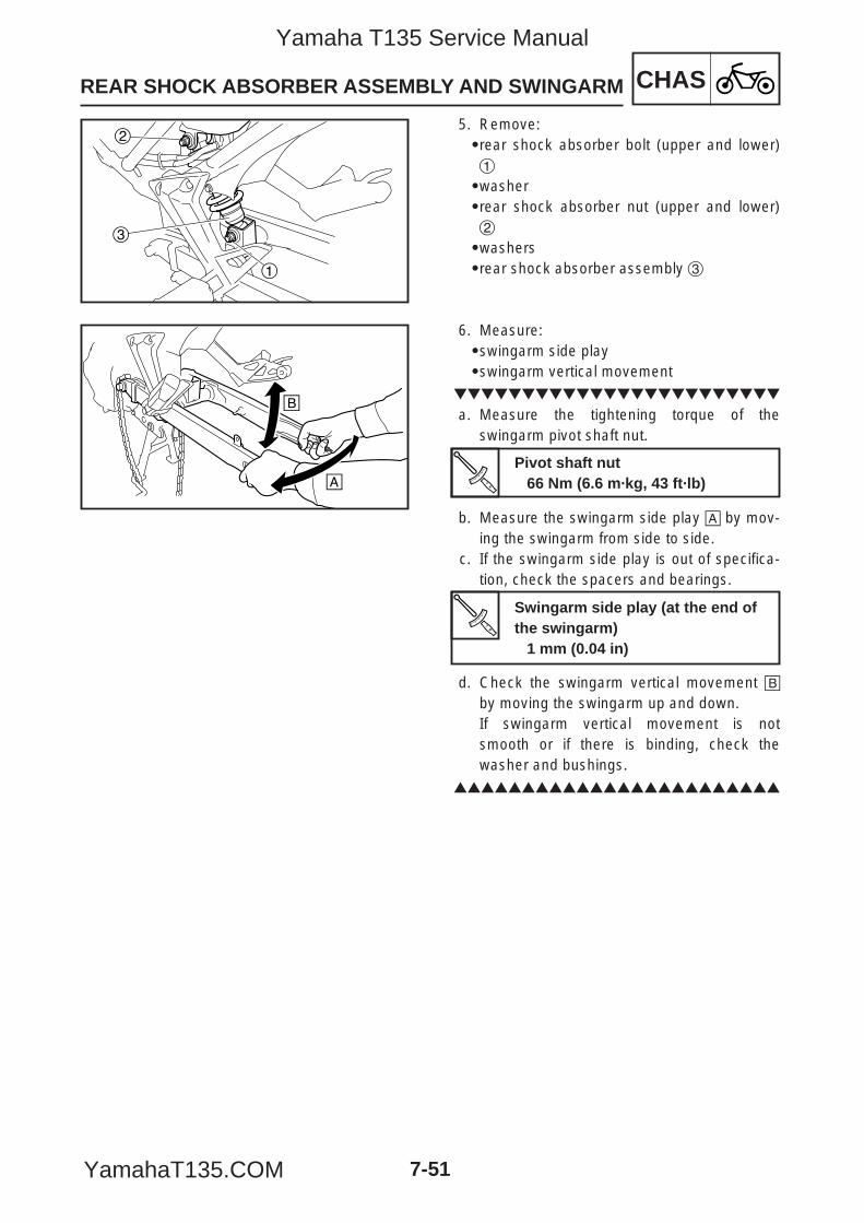
CHASREAR SHOCK ABSORBER ASSEMBLY AND SWINGARM
7-51
2
1
3
5. Remove:9rear shock absorber bolt (upper and lower)1
9washer9rear shock absorber nut (upper and lower)2
9washers9rear shock absorber assembly 3
å
∫
6. Measure:9swingarm side play9swingarm vertical movement
a. Measure the tightening torque of theswingarm pivot shaft nut.
b. Measure the swingarm side play å by mov-ing the swingarm from side to side.
c. If the swingarm side play is out of specifica-tion, check the spacers and bearings.
d. Check the swingarm vertical movement ∫by moving the swingarm up and down.If swingarm vertical movement is notsmooth or if there is binding, check thewasher and bushings.
Swingarm side play (at the end ofthe swingarm)
1 mm (0.04 in)
Pivot shaft nut66 Nm (6.6 m·kg, 43 ft·lb)
5YP-F8197-E0_7_1 05.6.27 19:30 Page 51
Yamaha T135 Service Manual
YamahaT135.COM
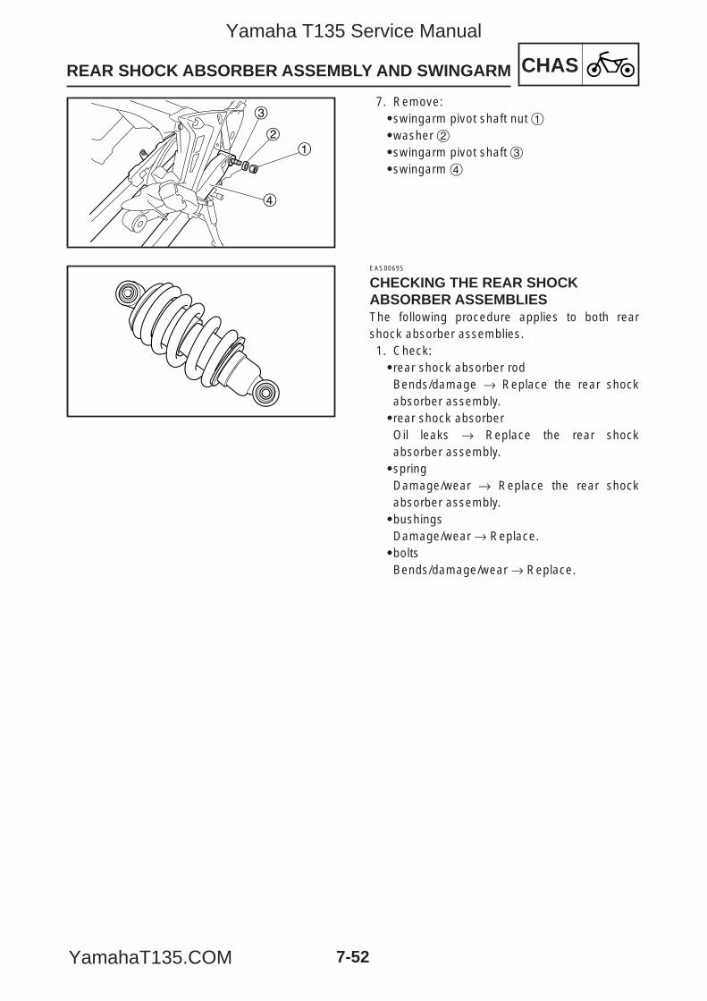
CHASREAR SHOCK ABSORBER ASSEMBLY AND SWINGARM
7-52
12
3
4
7. Remove:9swingarm pivot shaft nut 19washer 29swingarm pivot shaft 39swingarm 4
EAS00695
CHECKING THE REAR SHOCKABSORBER ASSEMBLIESThe following procedure applies to both rearshock absorber assemblies.1. Check:9rear shock absorber rodBends/damage → Replace the rear shockabsorber assembly.9rear shock absorberOil leaks → Replace the rear shockabsorber assembly.9springDamage/wear → Replace the rear shockabsorber assembly.9bushingsDamage/wear → Replace.9boltsBends/damage/wear → Replace.
5YP-F8197-E0_7_1 05.6.27 19:30 Page 52
Yamaha T135 Service Manual
YamahaT135.COM
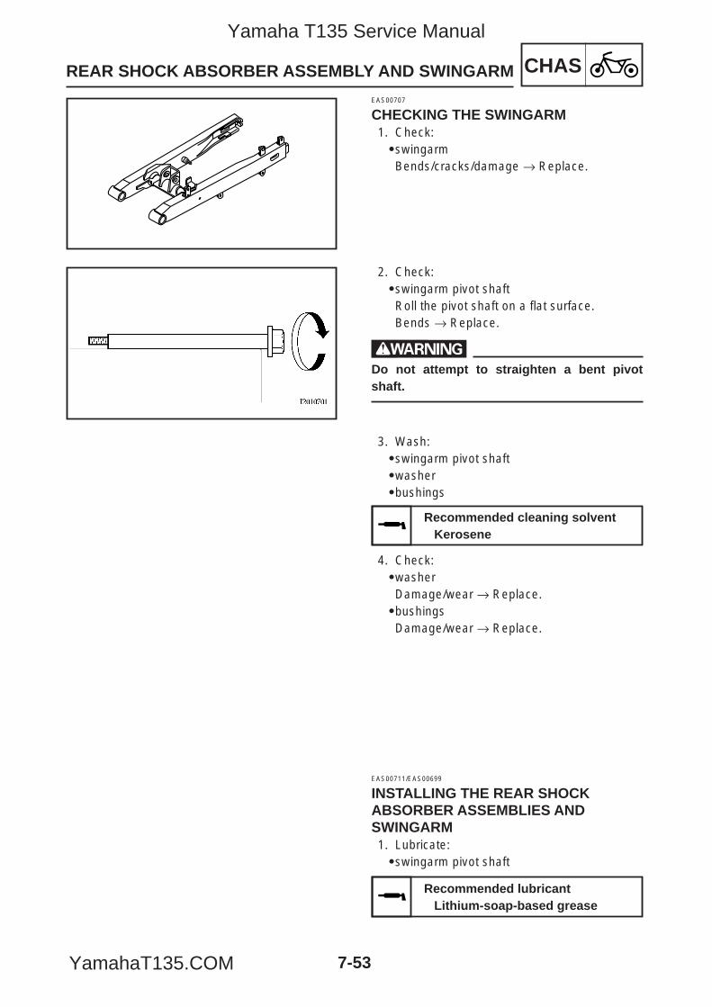
CHASREAR SHOCK ABSORBER ASSEMBLY AND SWINGARM
7-53
EAS00707
CHECKING THE SWINGARM1. Check:9swingarmBends/cracks/damage → Replace.
2. Check:9swingarm pivot shaftRoll the pivot shaft on a flat surface.Bends → Replace.
wDo not attempt to straighten a bent pivotshaft.
3. Wash:9swingarm pivot shaft9washer9bushings
4. Check:9washerDamage/wear → Replace.9bushingsDamage/wear → Replace.
EAS00711/EAS00699
INSTALLING THE REAR SHOCKABSORBER ASSEMBLIES ANDSWINGARM1. Lubricate:9swingarm pivot shaft
Recommended cleaning solventKerosene
Recommended lubricantLithium-soap-based grease
5YP-F8197-E0_7_1 05.6.27 19:30 Page 53
Yamaha T135 Service Manual
YamahaT135.COM
CHASREAR SHOCK ABSORBER ASSEMBLY AND SWINGARM
7-54
2. Install:9swingarm9swingarm pivot shaft9collar9swingarm pivot shaft nut
3. Install:9rear shock absorber assemblies9rear shock absorber nuts9rear shock absorber bolts
4. Install:9brake torque rod (to swingarm)
5. Install:9drive chain case
6. Install:9rear wheelRefer to “REAR WHEEL AND BRAKE”.9mufflerRefer to “REMOVING THE ENGINE” inchapter 4.9rear cowlings (left and right)Refer to “INSTALLING THE REAR COWL-INGS” in chapter 3.
66 Nm (6.6 m·kg, 48 ft·lb)
46 Nm (4.6 m·kg, 33 ft·lb)
16 Nm (1.6 m·kg, 12 ft·lb)
10 Nm (1.0 m·kg, 7.2 ft·lb)
5YP-F8197-E0_7_1 05.6.27 19:30 Page 54
Yamaha T135 Service Manual
YamahaT135.COM
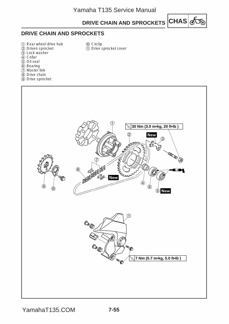
DRIVE CHAIN AND SPROCKETS CHAS
7-55
DRIVE CHAIN AND SPROCKETS
7 Nm (0.7 m•kg, 5.0 ft•lb )
30 Nm (3.0 m•kg, 20 ft•lb )
LS
7
1
23
46
5
8
q
90
1 Rear wheel drive hub 2 Driven sprocket3 Lock washer4 Collar5 Oil seal6 Bearing7 Master link8 Drive chain9 Drive sprocket
0 Circlipq Drive sprocket cover
5YP-F8197-E0_7_1 05.6.27 19:30 Page 55
Yamaha T135 Service Manual
YamahaT135.COM
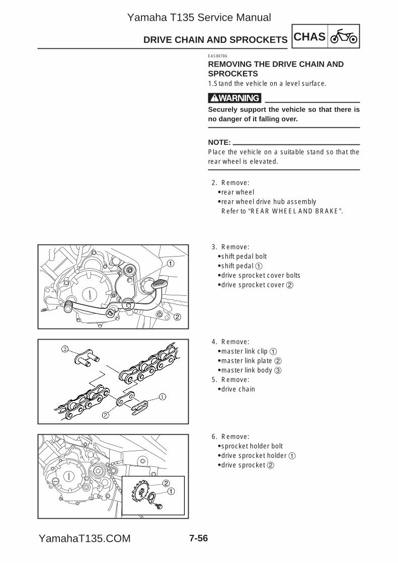
CHASDRIVE CHAIN AND SPROCKETS
7-56
EAS00706
REMOVING THE DRIVE CHAIN ANDSPROCKETS1.Stand the vehicle on a level surface.
wSecurely support the vehicle so that there isno danger of it falling over.
NOTE:Place the vehicle on a suitable stand so that therear wheel is elevated.
2. Remove:9rear wheel9rear wheel drive hub assemblyRefer to “REAR WHEEL AND BRAKE”.
2
1
3. Remove:9shift pedal bolt9shift pedal 19drive sprocket cover bolts9drive sprocket cover 2
4. Remove:9master link clip 19master link plate 29master link body 3
5. Remove:9drive chain
12
6. Remove:9sprocket holder bolt9drive sprocket holder 19drive sprocket 2
5YP-F8197-E0_7_1 05.6.27 19:30 Page 56
Yamaha T135 Service Manual
YamahaT135.COM
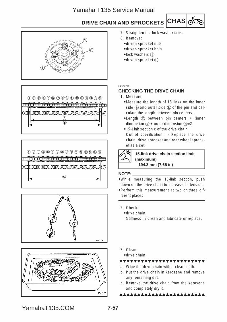
CHASDRIVE CHAIN AND SPROCKETS
7-57
1
1
2
7. Straighten the lock washer tabs.8. Remove:9driven sprocket nuts9driven sprocket bolts9lock washers 19driven sprocket 2
1 2 3 4 5 6 7 8 9 0 q w e r t
b
y
a
1 2 3 4 5 6 7 8 9 0 q w e r t
c
y
EAS00710
CHECKING THE DRIVE CHAIN1. Measure:9Measure the length of 15 links on the innerside a and outer side b of the pin and cal-culate the length between pin centers.9Length c between pin centers = (innerdimension a + outer dimension b)/2915-Link section c of the drive chainOut of specification → Replace the drivechain, drive sprocket and rear wheel sprock-et as a set.
NOTE:9While measuring the 15-link section, pushdown on the drive chain to increase its tension.9Perform this measurement at two or three dif-ferent places.
2. Check:9drive chainStiffness → Clean and lubricate or replace.
3. Clean:9drive chain
a. Wipe the drive chain with a clean cloth.b. Put the drive chain in kerosene and remove
any remaining dirt.c. Remove the drive chain from the kerosene
and completely dry it.
15-link drive chain section limit(maximum)
194.3 mm (7.65 in)
5YP-F8197-E0_7_1 05.6.27 19:30 Page 57
Yamaha T135 Service Manual
YamahaT135.COM
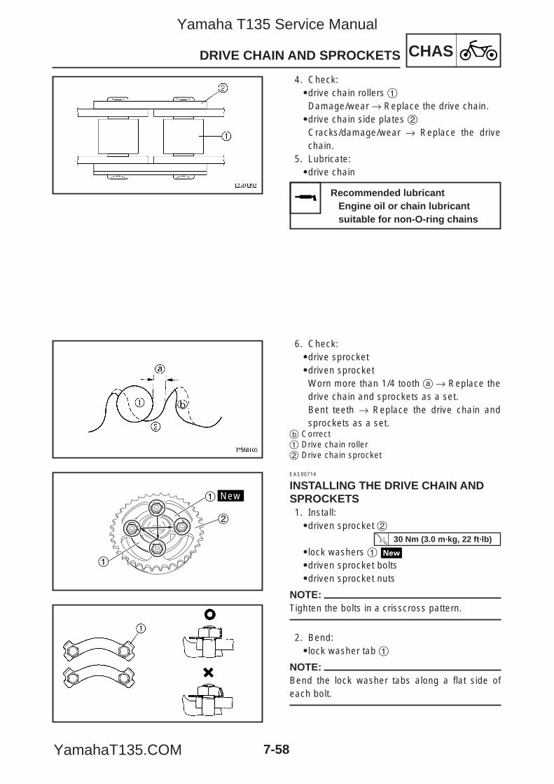
CHASDRIVE CHAIN AND SPROCKETS
7-58
4. Check:9drive chain rollers 1Damage/wear → Replace the drive chain.9drive chain side plates 2Cracks/damage/wear → Replace the drivechain.
5. Lubricate:9drive chain
6. Check:9drive sprocket9driven sprocketWorn more than 1/4 tooth a → Replace thedrive chain and sprockets as a set.Bent teeth → Replace the drive chain andsprockets as a set.
b Correct1 Drive chain roller2 Drive chain sprocket
New1
2
1
EAS00714
INSTALLING THE DRIVE CHAIN ANDSPROCKETS1. Install:9driven sprocket 2
9lock washers 19driven sprocket bolts9driven sprocket nuts
NOTE:Tighten the bolts in a crisscross pattern.
2. Bend:9lock washer tab 1
NOTE:Bend the lock washer tabs along a flat side ofeach bolt.
Recommended lubricantEngine oil or chain lubricant suitable for non-O-ring chains
30 Nm (3.0 m·kg, 22 ft·lb)
5YP-F8197-E0_7_1 05.6.27 19:30 Page 58
Yamaha T135 Service Manual
YamahaT135.COM
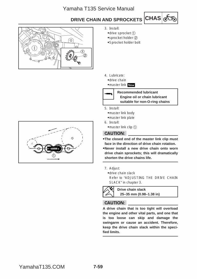
CHASDRIVE CHAIN AND SPROCKETS
7-59
21
3. Install:9drive sprocket 19sprocket holder 29Sprocket holder bolt
4. Lubricate:9drive chain9master link
5. Install:9master link body9master link plate
6. Install:9master link clip 1
cC99The closed end of the master link clip mustface in the direction of drive chain rotation.99Never install a new drive chain onto worndrive chain sprockets; this will dramaticallyshorten the drive chains life.
7. Adjust:9drive chain slackRefer to “ADJUSTING THE DRIVE CHAINSLACK” in chapter 3.
cCA drive chain that is too tight will overloadthe engine and other vital parts, and one thatis too loose can skip and damage theswingarm or cause an accident. Therefore,keep the drive chain slack within the speci-fied limits.
Recommended lubricantEngine oil or chain lubricant suitable for non-O-ring chains
Drive chain slack25–35 mm (0.98–1.38 in)
5YP-F8197-E0_7_1 05.6.27 19:30 Page 59
Yamaha T135 Service Manual
YamahaT135.COM

CHAS
5YP-F8197-E0_7_1 05.6.27 19:30 Page 60
Yamaha T135 Service Manual
YamahaT135.COM
ELEC
CHAPTER 8ELECTRICAL SYSTEM
ELECTRICAL COMPONENTS .............................................................................. 8-1
CHECKING SWITCH CONTINUITY ...................................................................... 8-3
CHECKING THE SWITCHES ................................................................................ 8-5
CHECKING THE BULBS AND BULB SOCKETS ................................................. 8-7TYPES OF BULBS ........................................................................................... 8-7CHECKING THE CONDITION OF THE BULBS ............................................... 8-8CHECKING THE CONDITION OF THE BULB SOCKETS ............................... 8-9
IGNITION SYSTEM ............................................................................................... 8-10CIRCUIT DIAGRAM .......................................................................................... 8-10TROUBLESHOOTING ...................................................................................... 8-11
ELECTRIC STARTING SYSTEM (T135SE) .......................................................... 8-15CIRCUIT DIAGRAM .......................................................................................... 8-15TROUBLESHOOTING ...................................................................................... 8-16
STARTER MOTOR (T135SE) ................................................................................ 8-18REMOVING THE STARTER MOTOR .............................................................. 8-19DISASSEMBLING THE STARTER MOTOR ..................................................... 8-19CHECKING THE STARTER MOTOR ............................................................... 8-19ASSEMBLING THE STARTER MOTOR ........................................................... 8-21INSTALLING THE STARTER MOTOR ............................................................. 8-21
CHARGING SYSTEM ............................................................................................ 8-22CIRCUIT DIAGRAM .......................................................................................... 8-22TROUBLESHOOTING ...................................................................................... 8-23
LIGHTING SYSTEM ............................................................................................... 8-25CIRCUIT DIAGRAM .......................................................................................... 8-25TROUBLESHOOTING ...................................................................................... 8-26CHECKING THE LIGHTING SYSTEM ............................................................. 8-27
SIGNALING SYSTEM ............................................................................................ 8-30CIRCUIT DIAGRAM .......................................................................................... 8-30TROUBLESHOOTING ...................................................................................... 8-32CHECKING THE SIGNALING SYSTEM .......................................................... 8-33
COOLING SYSTEM ................................................................................................8-40CIRCUIT DIAGRAM...........................................................................................8-40TROUBLESHOOTING.......................................................................................8-41
SELF-DIAGNOSIS ..................................................................................................8-44TROUBLESHOOTING.......................................................................................8-46
5YP-F8197-E0_8_1 05.6.27 19:27 Page A
Yamaha T135 Service Manual
YamahaT135.COM

ELEC
5YP-F8197-E0_8_1 05.6.27 19:27 Page B
Yamaha T135 Service Manual
YamahaT135.COM
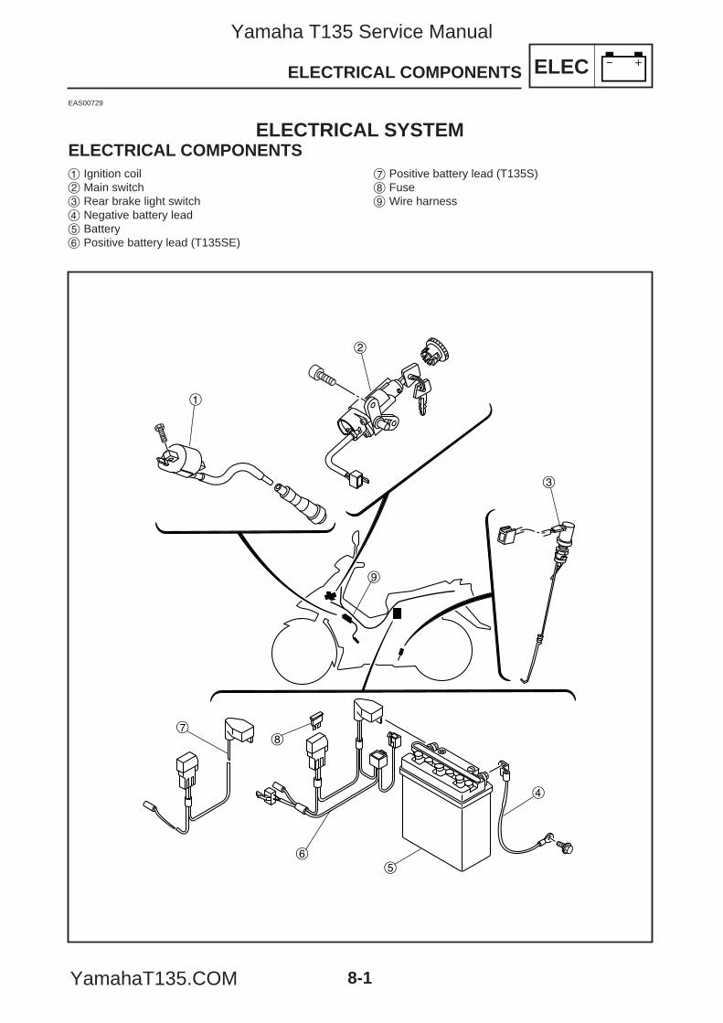
EAS00729
ELECTRICAL SYSTEMELECTRICAL COMPONENTS1 Ignition coil2 Main switch3 Rear brake light switch4 Negative battery lead5 Battery6 Positive battery lead (T135SE)
7 Positive battery lead (T135S)8 Fuse9 Wire harness
1
2
3
4
56
78
9
ELECELECTRICAL COMPONENTS
8-1
5YP-F8197-E0_8_1 05.6.27 19:27 Page 1
Yamaha T135 Service Manual
YamahaT135.COM
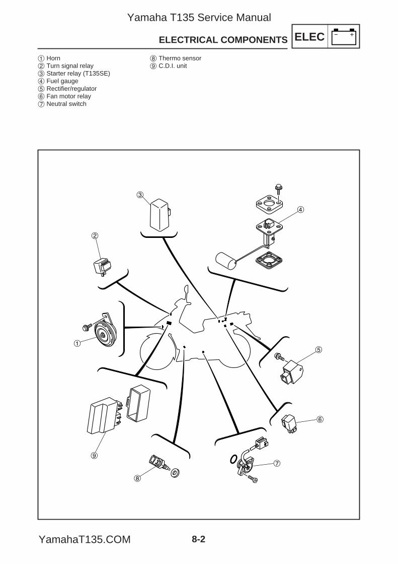
ELECELECTRICAL COMPONENTS
8-2
1 Horn2 Turn signal relay3 Starter relay (T135SE)4 Fuel gauge5 Rectifier/regulator6 Fan motor relay7 Neutral switch
8 Thermo sensor9 C.D.I. unit
2
1
3
4
5
6
7
8
9
5YP-F8197-E0_8_1 05.6.27 19:27 Page 2
Yamaha T135 Service Manual
YamahaT135.COM
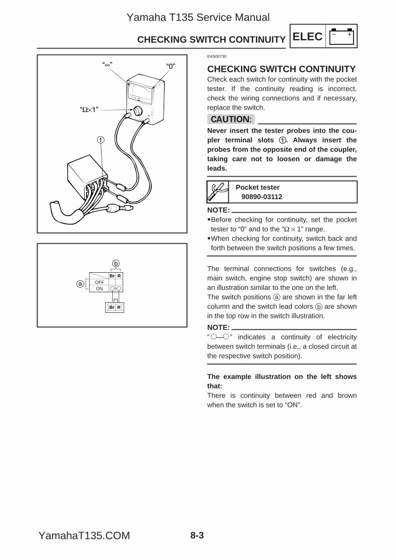
8-3
ELECCHECKING SWITCH CONTINUITY
1
OFFON
Br R
a
b
Br R
EAS00730
CHECKING SWITCH CONTINUITYCheck each switch for continuity with the pockettester. If the continuity reading is incorrect,check the wiring connections and if necessary,replace the switch.
cCNever insert the tester probes into the cou-pler terminal slots 11. Always insert theprobes from the opposite end of the coupler,taking care not to loosen or damage theleads.
NOTE:9Before checking for continuity, set the pockettester to “0” and to the “Ω × 1” range.9When checking for continuity, switch back andforth between the switch positions a few times.
The terminal connections for switches (e.g.,main switch, engine stop switch) are shown inan illustration similar to the one on the left.The switch positions a are shown in the far leftcolumn and the switch lead colors b are shownin the top row in the switch illustration.
NOTE:“1—1” indicates a continuity of electricitybetween switch terminals (i.e., a closed circuit atthe respective switch position).
The example illustration on the left showsthat:There is continuity between red and brownwhen the switch is set to “ON”.
Pocket tester90890-03112
5YP-F8197-E0_8_1 05.6.27 19:27 Page 3
Yamaha T135 Service Manual
YamahaT135.COM
ELECCHECKING SWITCH CONTINUITY
8-4
5YP-F8197-E0_8_1 05.6.27 19:27 Page 4
Yamaha T135 Service Manual
YamahaT135.COM
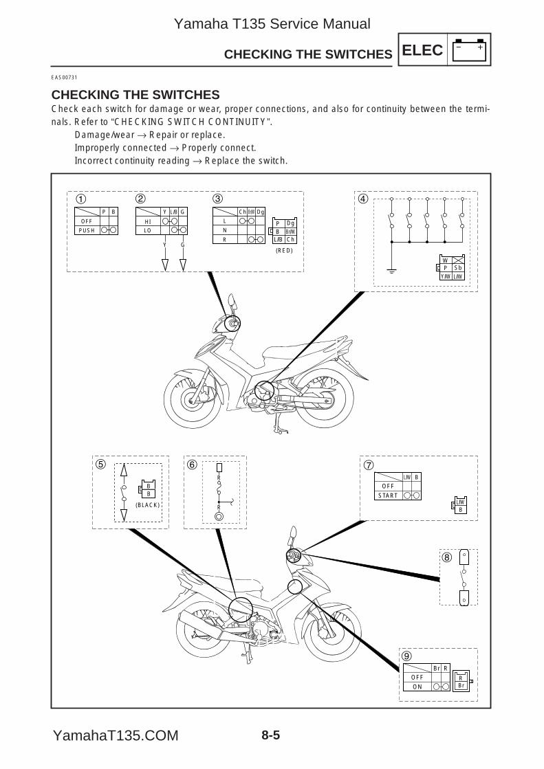
L
N
R
Ch Br/W Dg
HI
LO
Y L /B G
OFF
P B
PUSH
GY
RBr
OFFBr R
ON
OFFL/W B
START
BL/W
Br/WCh
BDg
L/B
P
(RED)
Y/W L/W
WSbP
(BLACK)
BB
R
R
1 2 3 4
5 6 7
8
9
CHECKING THE SWITCHES
EAS00731
CHECKING THE SWITCHESCheck each switch for damage or wear, proper connections, and also for continuity between the termi-nals. Refer to “CHECKING SWITCH CONTINUITY”.
Damage/wear → Repair or replace.Improperly connected → Properly connect.Incorrect continuity reading → Replace the switch.
ELEC
8-5
5YP-F8197-E0_8_1 05.6.27 19:27 Page 5
Yamaha T135 Service Manual
YamahaT135.COM
ELEC
8-6
CHECKING THE SWITCHES
1 Horn switch2 Dimmer switch3 Turn signal switch4 Neutral switch5 Rear brake light switch6 Fuse7 Start switch8 Front brake light switch9 Main switch
5YP-F8197-E0_8_1 05.6.27 19:27 Page 6
Yamaha T135 Service Manual
YamahaT135.COM
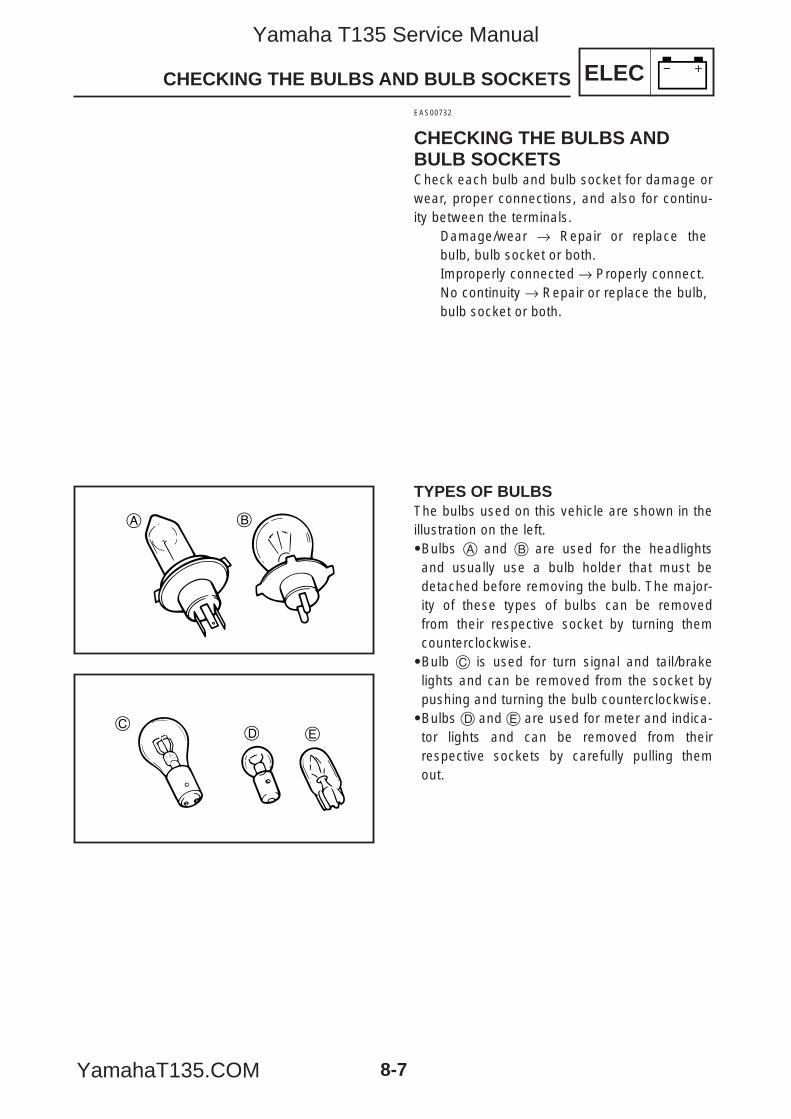
ELEC
8-7
CHECKING THE BULBS AND BULB SOCKETS
EAS00732
CHECKING THE BULBS ANDBULB SOCKETSCheck each bulb and bulb socket for damage orwear, proper connections, and also for continu-ity between the terminals.
Damage/wear → Repair or replace thebulb, bulb socket or both.Improperly connected → Properly connect.No continuity → Repair or replace the bulb,bulb socket or both.
TYPES OF BULBSThe bulbs used on this vehicle are shown in theillustration on the left.9Bulbs A and B are used for the headlightsand usually use a bulb holder that must bedetached before removing the bulb. The major-ity of these types of bulbs can be removedfrom their respective socket by turning themcounterclockwise.9Bulb C is used for turn signal and tail/brakelights and can be removed from the socket bypushing and turning the bulb counterclockwise.9Bulbs D and E are used for meter and indica-tor lights and can be removed from theirrespective sockets by carefully pulling themout.
A B
CD E
5YP-F8197-E0_8_1 05.6.27 19:27 Page 7
Yamaha T135 Service Manual
YamahaT135.COM
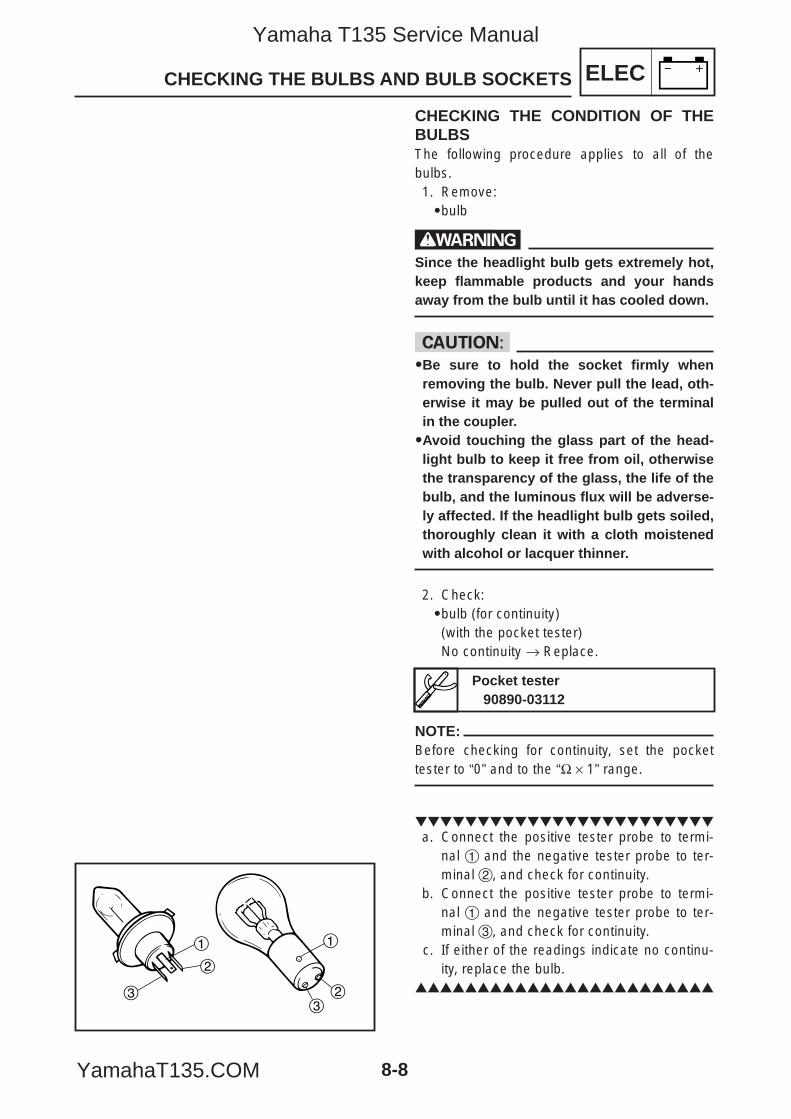
ELEC
8-8
CHECKING THE BULBS AND BULB SOCKETS
CHECKING THE CONDITION OF THEBULBSThe following procedure applies to all of thebulbs.1. Remove:9bulb
wSince the headlight bulb gets extremely hot,keep flammable products and your handsaway from the bulb until it has cooled down.
cC99Be sure to hold the socket firmly whenremoving the bulb. Never pull the lead, oth-erwise it may be pulled out of the terminalin the coupler.99Avoid touching the glass part of the head-light bulb to keep it free from oil, otherwisethe transparency of the glass, the life of thebulb, and the luminous flux will be adverse-ly affected. If the headlight bulb gets soiled,thoroughly clean it with a cloth moistenedwith alcohol or lacquer thinner.
2. Check:9bulb (for continuity)(with the pocket tester)No continuity → Replace.
NOTE:Before checking for continuity, set the pockettester to “0” and to the “Ω × 1” range.
a. Connect the positive tester probe to termi-
nal 1 and the negative tester probe to ter-minal 2, and check for continuity.
b. Connect the positive tester probe to termi-nal 1 and the negative tester probe to ter-minal 3, and check for continuity.
c. If either of the readings indicate no continu-ity, replace the bulb.
Pocket tester90890-03112
1
2
3
1
23
5YP-F8197-E0_8_1 05.6.27 19:27 Page 8
Yamaha T135 Service Manual
YamahaT135.COM
ELECCHECKING THE BULBS AND BULB SOCKETS
8-9
CHECKING THE CONDITION OF THEBULB SOCKETSThe following procedure applies to all of thebulb sockets.1. Check:9bulb socket (for continuity)(with the pocket tester)No continuity → Replace.
NOTE:Check each bulb socket for continuity in thesame manner as described in the bulb section;however, note the following.
a. Install a good bulb into the bulb socket.b. Connect the pocket tester probes to the
respective leads of the bulb socket.c. Check the bulb socket for continuity. If any
of the readings indicate no continuity,replace the bulb socket.
Pocket tester90890-03112
5YP-F8197-E0_8_1 05.6.27 19:27 Page 9
Yamaha T135 Service Manual
YamahaT135.COM
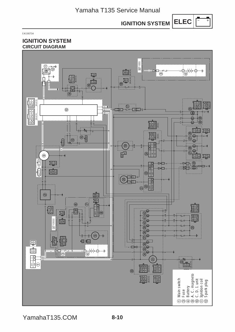
ELEC
8-10
IGNITION SYSTEM
EAS00734
IGNITION SYSTEMCIRCUIT DIAGRAM
R Br
WW
OF
F
ON
Br
R
R
OF
F
ST
AR
T
B
L/W
L/W
B
BS
bW
PY
/W
Y/W
L/W
L/W
Sb
WP
G G
LD
gC
hB
r
BG
RBr
Br
RBr
L/W
L/W
R/W
R/W
R/W
Y
Sb
Y/W
PL/
WW
L/W
G/W
G/W
Sb W
Y/W
P
Br
L Dg
GB
Ch
Dg B
Br
Ch
L
G
(BLA
CK
)
(BLA
CK
)(B
LAC
K)
(BLA
CK
)(B
LAC
K)
(BLA
CK
) (BLA
CK
)(B
LAC
K)
(BLA
CK
)
Y/W
L/WSb
Y/W
L/W
WW
Sb
PP
RR
B
WB
Br
Br
Br
L/Y
W
B
BB
R
R
OO
W Y/R B
Y BW
Br
L/W
Br
L/W
BBL/W
L/W
B/L
G/R
G/R
G/W
B
Br
G/Y
G/Y
G/Y
Br
Br/
W
Br/
W
Br/
W Br
Y/R
L N R
Ch
Dg
LG
/Y
P
B
YG G
YY
P
HI
LO
OF
F
PU
SH
Br/W
Ch
BD
g
L/B
W/Y
Y
PB Y/R
Br/W
P
Ch
Dg (RE
D)
(RE
D)
Br
BB
B
Ch
Dg
Ch
Dg BLL
B BL L
BL Y
Ch
Dg
G/Y Dg
BL
Ch
RW
WR
B/L
B/L
LY
G B
LP W
Br
B O
Y/R
Y/R
Y/R
WW
RR/W
BrR
BLBL
BB
R/W
R
L YY
L L
PL
Br
B/L
B/L
B/L
Br
G/W
Y/W
Y/W
G/R
G/R
G/W
B
B
Ch
Dg
Ch
Dg
LL
Br
Br
1
2
3 4
5
6 7
8
9
0
q
w
er
y
t
u
ip
o
a sd
f
gj
j
hh
kk
l
;
z
x
v
c
bn
m,
./
!@
RR
3 4
åT
135S
E
∫T
135S
R
L/W
R Br
R/W
L/W
R Br
R/W
1M
ain
switc
h3
Fus
e4
Bat
tery
9A
. C. m
agne
to0
C. D
. I. u
nit
qIg
nitio
n co
ilw
Spa
rk p
lug
5YP-F8197-E0_8_1 05.6.27 19:27 Page 10
Yamaha T135 Service Manual
YamahaT135.COM
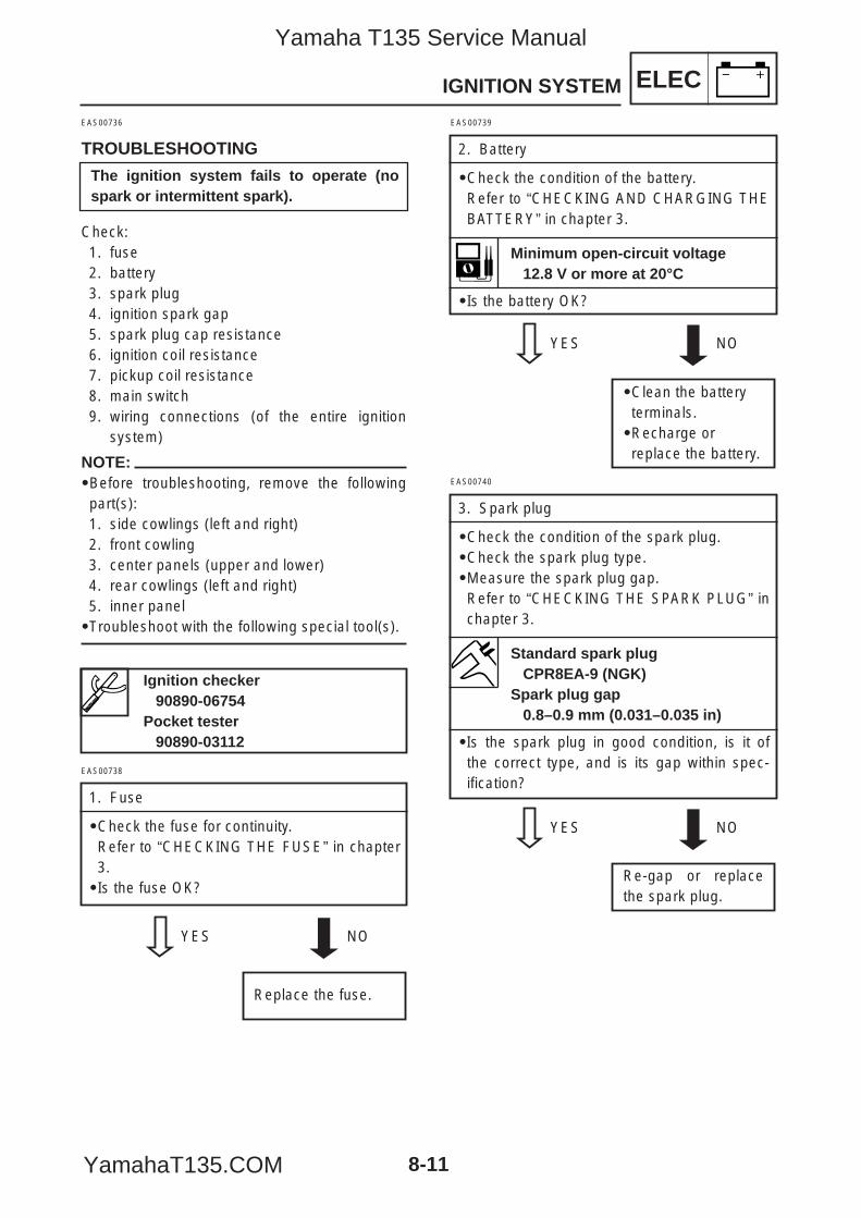
ELEC
8-11
IGNITION SYSTEM
EAS00736
TROUBLESHOOTING
Check:1. fuse2. battery3. spark plug4. ignition spark gap5. spark plug cap resistance6. ignition coil resistance7. pickup coil resistance8. main switch9. wiring connections (of the entire ignition
system)
NOTE:9Before troubleshooting, remove the followingpart(s):1. side cowlings (left and right)2. front cowling3. center panels (upper and lower)4. rear cowlings (left and right)5. inner panel9Troubleshoot with the following special tool(s).
Ignition checker90890-06754
Pocket tester90890-03112
The ignition system fails to operate (nospark or intermittent spark).
EAS00738
1. Fuse
9Check the fuse for continuity.Refer to “CHECKING THE FUSE” in chapter3.9Is the fuse OK?
YES NO
Replace the fuse.
EAS00739
2. Battery
9Check the condition of the battery.Refer to “CHECKING AND CHARGING THEBATTERY” in chapter 3.
9Is the battery OK?
YES NO
9Clean the batteryterminals.9Recharge orreplace the battery.
Minimum open-circuit voltage12.8 V or more at 20°C
EAS00740
3. Spark plug
9Check the condition of the spark plug.9Check the spark plug type.9Measure the spark plug gap.Refer to “CHECKING THE SPARK PLUG” inchapter 3.
9Is the spark plug in good condition, is it ofthe correct type, and is its gap within spec-ification?
YES NO
Re-gap or replacethe spark plug.
Standard spark plugCPR8EA-9 (NGK)
Spark plug gap0.8–0.9 mm (0.031–0.035 in)
5YP-F8197-E0_8_1 05.6.27 19:27 Page 11
Yamaha T135 Service Manual
YamahaT135.COM
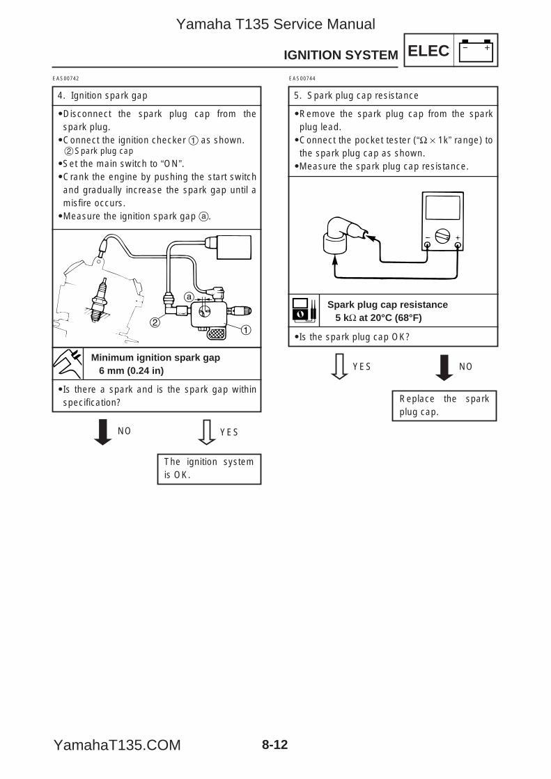
ELEC
8-12
IGNITION SYSTEM
EAS00744
5. Spark plug cap resistance
9Remove the spark plug cap from the sparkplug lead.9Connect the pocket tester (“Ω × 1k” range) tothe spark plug cap as shown.9Measure the spark plug cap resistance.
9Is the spark plug cap OK?
YES NO
Replace the sparkplug cap.
Spark plug cap resistance5 kΩ at 20°C (68°F)
EAS00742
4. Ignition spark gap
9Disconnect the spark plug cap from thespark plug.9Connect the ignition checker 1 as shown.2Spark plug cap
9Set the main switch to “ON”.9Crank the engine by pushing the start switchand gradually increase the spark gap until amisfire occurs.9Measure the ignition spark gap a.
9Is there a spark and is the spark gap withinspecification?
YESNO
The ignition systemis OK.
2
a
1
Minimum ignition spark gap6 mm (0.24 in)
5YP-F8197-E0_8_1 05.6.27 19:27 Page 12
Yamaha T135 Service Manual
YamahaT135.COM
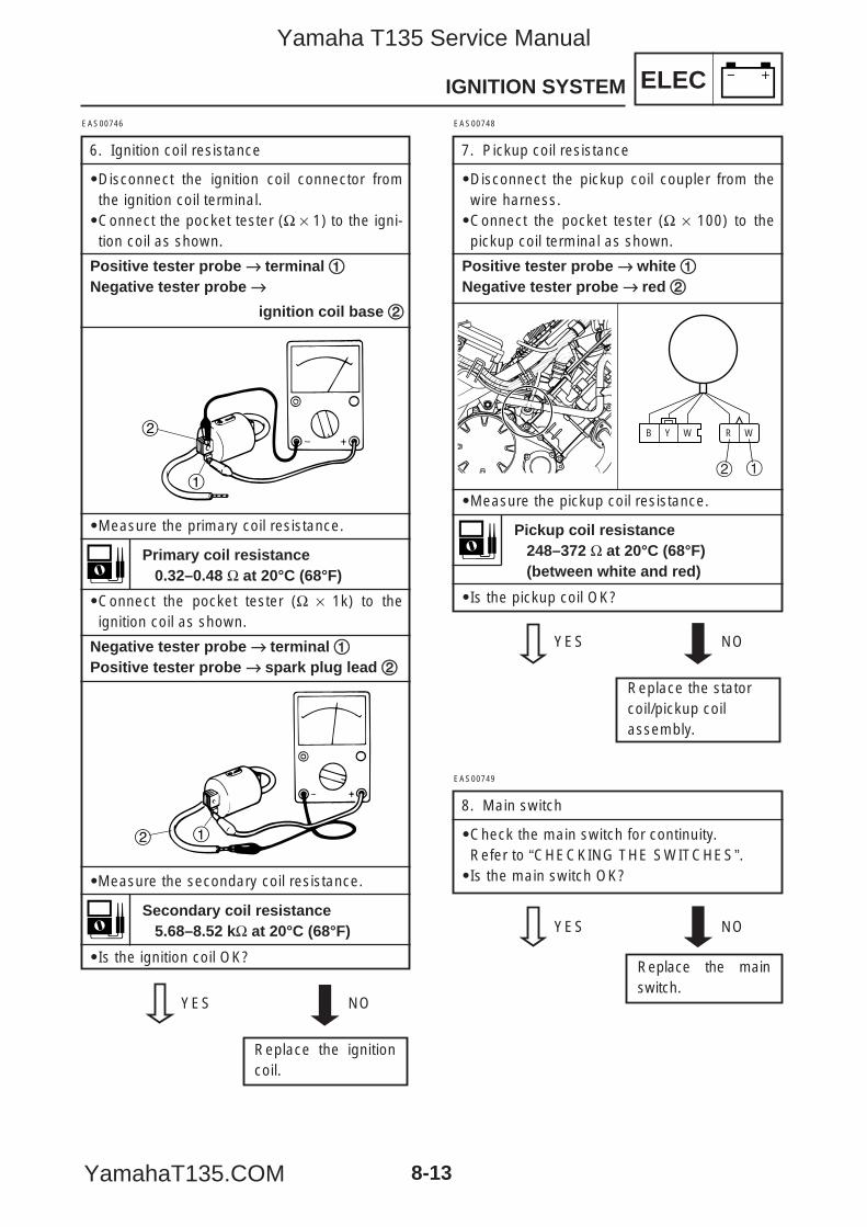
ELEC
8-13
IGNITION SYSTEM
EAS00749
8. Main switch
9Check the main switch for continuity.Refer to “CHECKING THE SWITCHES”.9Is the main switch OK?
YES NO
Replace the mainswitch.
EAS00746
6. Ignition coil resistance
9Disconnect the ignition coil connector fromthe ignition coil terminal.9Connect the pocket tester (Ω × 1) to the igni-tion coil as shown.
Positive tester probe →→ terminal 11Negative tester probe →→
ignition coil base 22
9Measure the primary coil resistance.
9Connect the pocket tester (Ω × 1k) to theignition coil as shown.
Negative tester probe →→ terminal 11Positive tester probe →→ spark plug lead 22
9Measure the secondary coil resistance.
9Is the ignition coil OK?
1
2
12
Primary coil resistance0.32–0.48 Ω at 20°C (68°F)
EAS00748
7. Pickup coil resistance
9Disconnect the pickup coil coupler from thewire harness.9Connect the pocket tester (Ω × 100) to thepickup coil terminal as shown.
Positive tester probe →→ white 11Negative tester probe →→ red 22
9Measure the pickup coil resistance.
9Is the pickup coil OK?
WRWYB
12
Pickup coil resistance248–372 Ω at 20°C (68°F)(between white and red)
Secondary coil resistance5.68–8.52 kΩ at 20°C (68°F)
YES NO
Replace the ignitioncoil.
YES NO
Replace the statorcoil/pickup coilassembly.
5YP-F8197-E0_8_1 05.6.27 19:27 Page 13
Yamaha T135 Service Manual
YamahaT135.COM
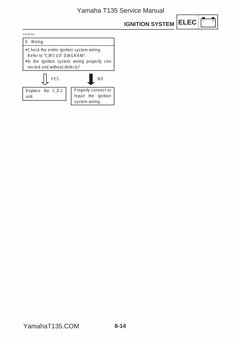
ELECIGNITION SYSTEM
8-14
EAS00754
9. Wiring
9Check the entire ignition system wiring.Refer to “CIRCUIT DIAGRAM”.9Is the ignition system wiring properly con-nected and without defects?
YES NO
Properly connect orrepair the ignitionsystem wiring.
Replace the C.D.I.unit.
5YP-F8197-E0_8_1 05.6.27 19:27 Page 14
Yamaha T135 Service Manual
YamahaT135.COM
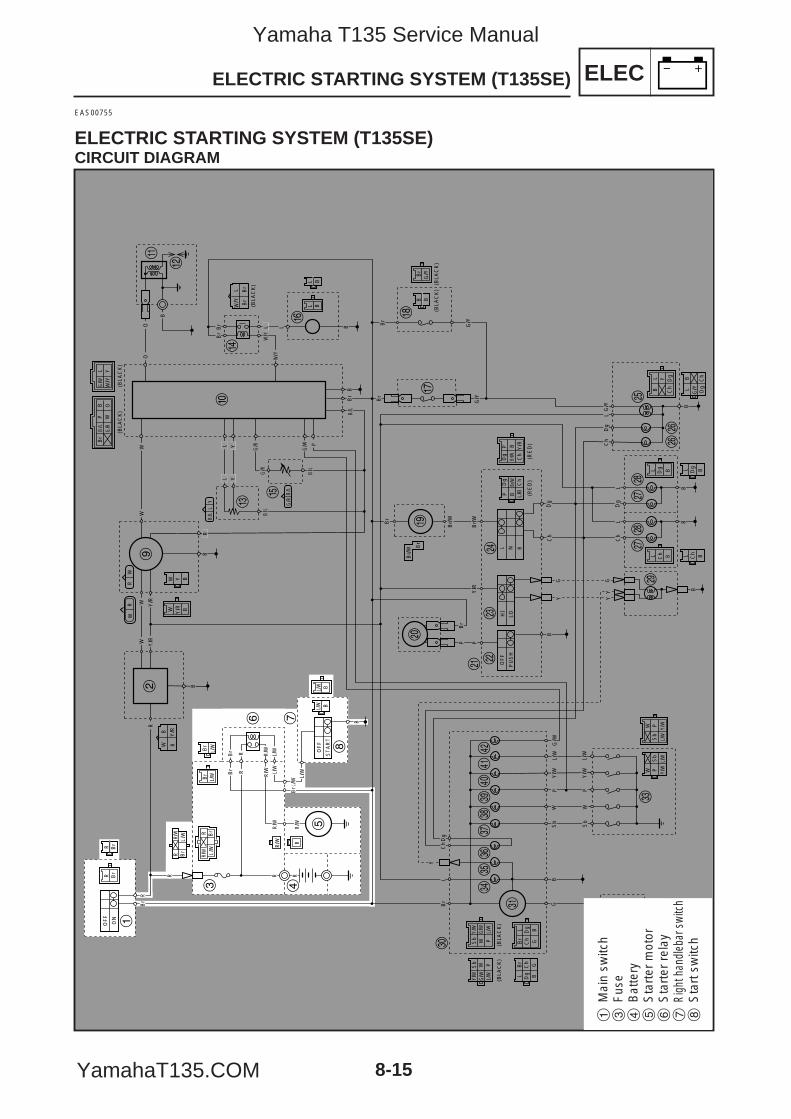
EAS00755
ELECTRIC STARTING SYSTEM (T135SE)CIRCUIT DIAGRAM
R Br
WW
OF
F
ON
Br
R
R
OF
F
ST
AR
T
B
L/W
L/W
B
BS
bW
PY
/W
Y/W
L/W
L/W
Sb
WP
G G
LD
gC
hB
r
BG
RBr
Br
RBr
L/W
L/W
R/W
R/W
R/W
Y
Sb
Y/W
PL/
WW
L/W
G/W
G/W
Sb W
Y/W
P
Br
L Dg
GB
Ch
Dg B
Br
Ch
L
G
(BLA
CK
)
(BLA
CK
)(B
LAC
K)
(BLA
CK
)(B
LAC
K)
(BLA
CK
) (BLA
CK
)(B
LAC
K)
(BLA
CK
)
Y/W
L/WSb
Y/W
L/W
WW
Sb
PP
RR
B
WB
Br
Br
Br
L/Y
W
B
BB
R
R
OO
W Y/R B
Y BW
Br
L/W
Br
L/W
BBL/W
L/W
B/L
G/R
G/R
G/W
B
Br
G/Y
G/Y
G/Y
Br
Br/
W
Br/
W
Br/
W Br
Y/R
L N R
Ch
Dg
LG
/Y
P
B
YG G
YY
P
HI
LO
OF
F
PU
SH
Br/W Ch
BD
g
L/B
W/Y
Y
PB Y/R
Br/W
P
Ch
Dg (R
ED
)(R
ED
)
Br
BB
B
Ch
Dg
Ch
Dg BLL
B BL L
BL Y
Ch
Dg
G/Y Dg
BL
Ch
RW
WR
B/L
B/L
LY
G B
LP W
Br
B O
Y/R
Y/R
Y/R
WW
RR/W
BrR
BLBL
BB
R/W
R
L YY
L L
PL
Br
B/L
B/L
B/L
Br
G/W
Y/W
Y/W
G/R
G/R
G/W
B
B
Ch
Dg
Ch
Dg
LL
Br
Br
L/W
R Br
R/W
L/W
R Br
R/W
1
2
3 4
5
6 7
8
9
0
q
w
er
y
t
u
ip
o
a sd
f
gj
j
hh
kk
l
;
z
x
v
c
bn
m,
./
!@
ELECELECTRIC STARTING SYSTEM (T135SE)
8-15
1M
ain
switc
h3
Fus
e4
Bat
tery
5S
tart
er m
otor
6S
tart
er r
elay
7Ri
ght h
andl
ebar
swi
tch
8S
tart
sw
itch
5YP-F8197-E0_8_1 05.6.27 19:27 Page 15
Yamaha T135 Service Manual
YamahaT135.COM
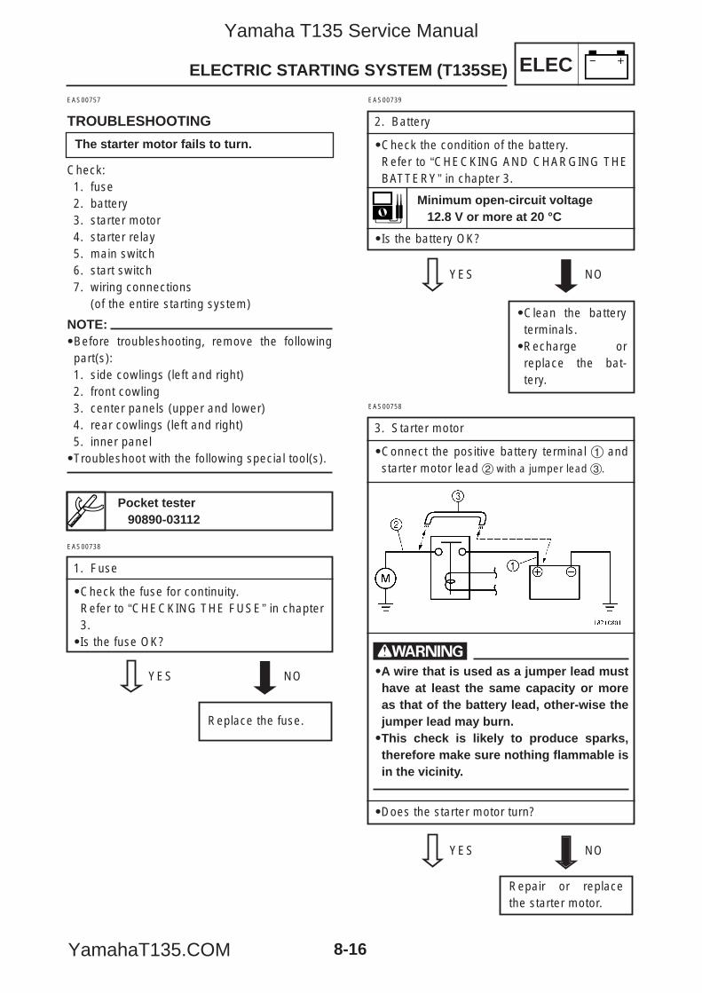
ELECELECTRIC STARTING SYSTEM (T135SE)
8-16
EAS00758
3. Starter motor
9Connect the positive battery terminal 1 andstarter motor lead 2 with a jumper lead 3.
w9A wire that is used as a jumper lead musthave at least the same capacity or moreas that of the battery lead, other-wise thejumper lead may burn.9This check is likely to produce sparks,therefore make sure nothing flammable isin the vicinity.
9Does the starter motor turn?
YES NO
Repair or replacethe starter motor.
EAS00757
TROUBLESHOOTING
Check:1. fuse2. battery3. starter motor4. starter relay5. main switch6. start switch7. wiring connections
(of the entire starting system)
NOTE:9Before troubleshooting, remove the followingpart(s):1. side cowlings (left and right)2. front cowling3. center panels (upper and lower)4. rear cowlings (left and right)5. inner panel9Troubleshoot with the following special tool(s).
EAS00739
2. Battery
9Check the condition of the battery.Refer to “CHECKING AND CHARGING THEBATTERY” in chapter 3.
9Is the battery OK?
YES NO
9Clean the batteryterminals.9Recharge orreplace the bat-tery.
Pocket tester90890-03112
Minimum open-circuit voltage12.8 V or more at 20 °C
EAS00738
1. Fuse
9Check the fuse for continuity.Refer to “CHECKING THE FUSE” in chapter3.9Is the fuse OK?
YES NO
Replace the fuse.
The starter motor fails to turn.
5YP-F8197-E0_8_1 05.6.27 19:27 Page 16
Yamaha T135 Service Manual
YamahaT135.COM
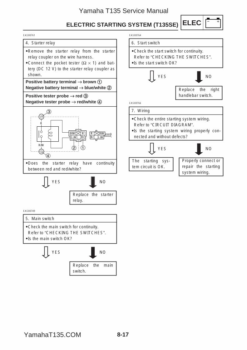
ELECELECTRIC STARTING SYSTEM (T135SE)
8-17
EAS00761
4. Starter relay
9Remove the starter relay from the starterrelay coupler on the wire harness.9Connect the pocket tester (Ω × 1) and bat-tery (DC 12 V) to the starter relay coupler asshown.
Positive battery terminal →→ brown 11Negative battery terminal →→ blue/white 22
Positive tester probe →→ red 33Negative tester probe →→ red/white 44
9Does the starter relay have continuitybetween red and red/white?
YES NO
Replace the starterrelay.
R
R/W
3
4
2 1
L /WRBr
R/WL /W
RBr
R/W
Properly connect orrepair the startingsystem wiring.
The starting sys-tem circuit is OK.
EAS00766
7. Wiring
9Check the entire starting system wiring.Refer to “CIRCUIT DIAGRAM”.9Is the starting system wiring properly con-nected and without defects?
YES NO
EAS00749
5. Main switch
9Check the main switch for continuity.Refer to “CHECKING THE SWITCHES”.9Is the main switch OK?
YES NO
Replace the mainswitch.
EAS00764
6. Start switch
9Check the start switch for continuity.Refer to “CHECKING THE SWITCHES”.9Is the start switch OK?
YES NO
Replace the righthandlebar switch.
5YP-F8197-E0_8_1 05.6.27 19:27 Page 17
Yamaha T135 Service Manual
YamahaT135.COM
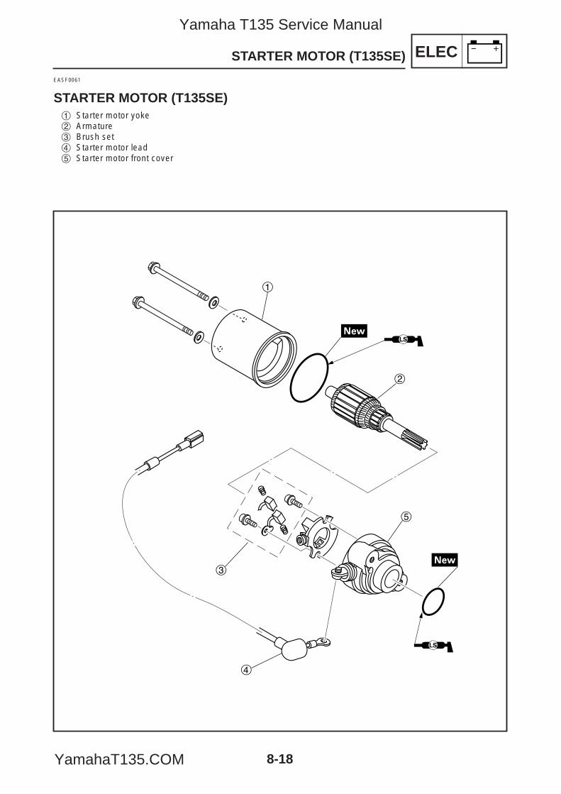
ELECSTARTER MOTOR (T135SE)
8-18
EASF0061
STARTER MOTOR (T135SE)1 Starter motor yoke2 Armature3 Brush set4 Starter motor lead5 Starter motor front cover
1
2
3
5
4
5YP-F8197-E0_8_1 05.6.27 19:27 Page 18
Yamaha T135 Service Manual
YamahaT135.COM
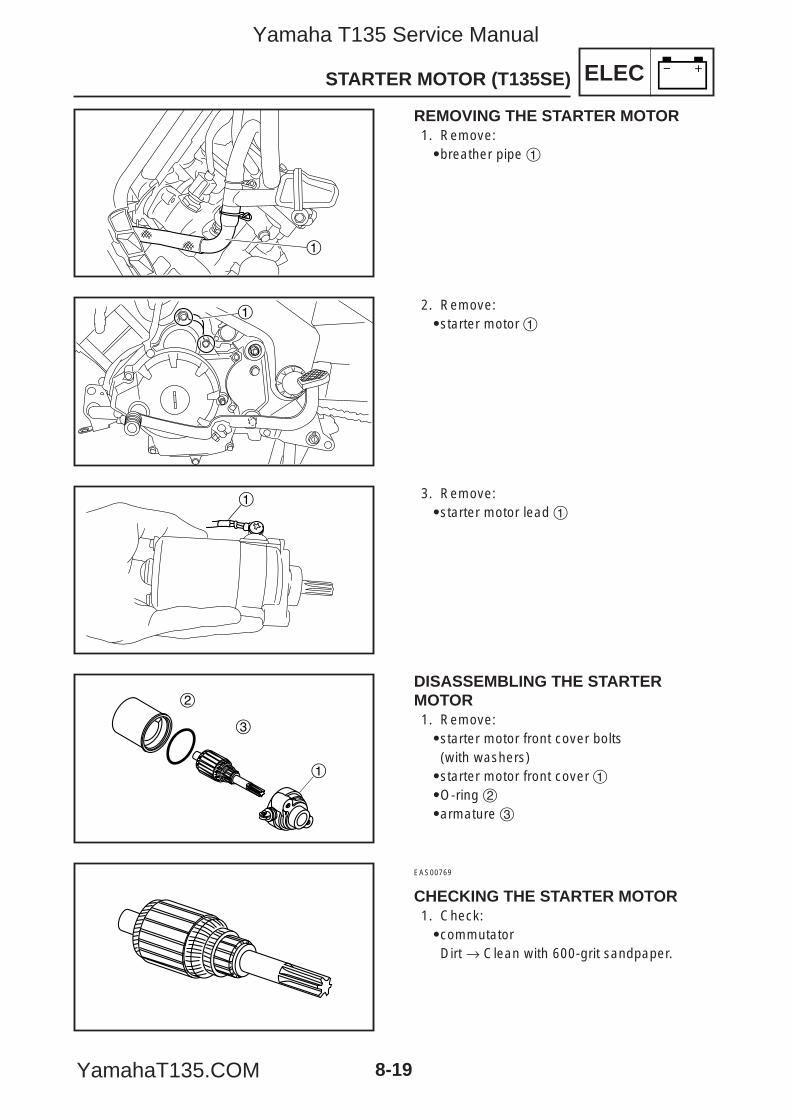
ELECSTARTER MOTOR (T135SE)
8-19
1
1
1
2
3
REMOVING THE STARTER MOTOR1. Remove:9breather pipe 1
2. Remove:9starter motor 1
3. Remove:9starter motor lead 1
DISASSEMBLING THE STARTER MOTOR1. Remove:9starter motor front cover bolts(with washers)9starter motor front cover 19O-ring 29armature 3
EAS00769
CHECKING THE STARTER MOTOR1. Check:9commutatorDirt → Clean with 600-grit sandpaper.
1
5YP-F8197-E0_8_1 05.6.27 19:27 Page 19
Yamaha T135 Service Manual
YamahaT135.COM
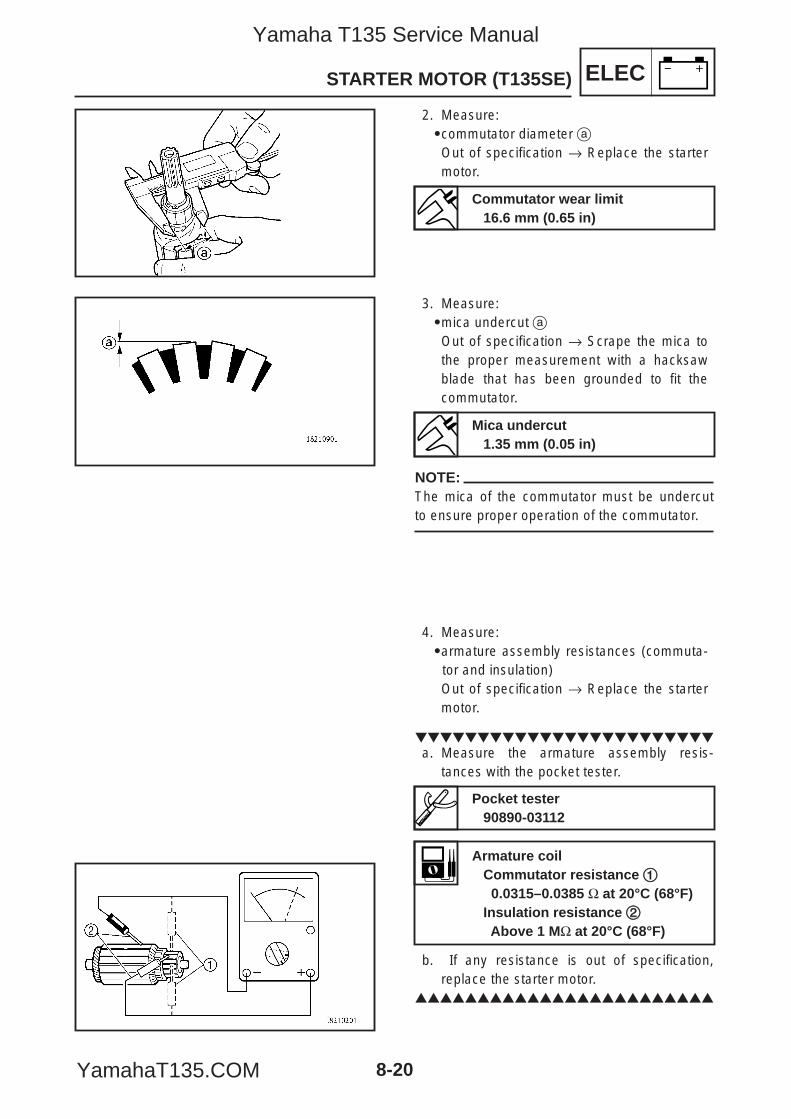
ELECSTARTER MOTOR (T135SE)
8-20
2. Measure:9commutator diameter aOut of specification → Replace the startermotor.
3. Measure:9mica undercut aOut of specification → Scrape the mica tothe proper measurement with a hacksawblade that has been grounded to fit thecommutator.
NOTE:The mica of the commutator must be undercutto ensure proper operation of the commutator.
4. Measure:9armature assembly resistances (commuta-
tor and insulation)Out of specification → Replace the startermotor.
a. Measure the armature assembly resis-
tances with the pocket tester.
b. If any resistance is out of specification,replace the starter motor.
Commutator wear limit16.6 mm (0.65 in)
Mica undercut1.35 mm (0.05 in)
Pocket tester90890-03112
Armature coilCommutator resistance 11
0.0315–0.0385 Ω at 20°C (68°F)Insulation resistance 22Above 1 MΩ at 20°C (68°F)
5YP-F8197-E0_8_1 05.6.27 19:27 Page 20
Yamaha T135 Service Manual
YamahaT135.COM
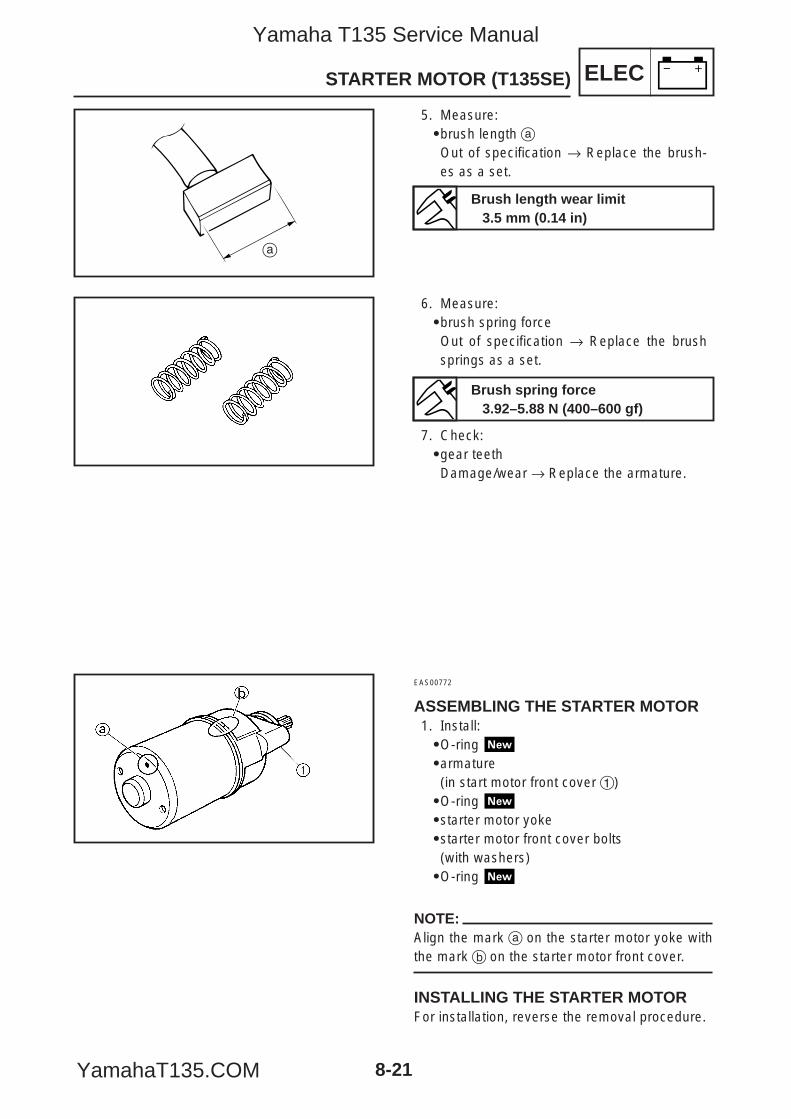
ELECSTARTER MOTOR (T135SE)
8-21
a
5. Measure:9brush length aOut of specification → Replace the brush-es as a set.
6. Measure:9brush spring force Out of specification → Replace the brushsprings as a set.
7. Check:9gear teethDamage/wear → Replace the armature.
EAS00772
ASSEMBLING THE STARTER MOTOR1. Install:9O-ring 9armature(in start motor front cover 1)9O-ring 9starter motor yoke9starter motor front cover bolts(with washers)9O-ring
NOTE:Align the mark a on the starter motor yoke withthe mark b on the starter motor front cover.
INSTALLING THE STARTER MOTORFor installation, reverse the removal procedure.
Brush length wear limit3.5 mm (0.14 in)
Brush spring force3.92–5.88 N (400–600 gf)
5YP-F8197-E0_8_1 05.6.27 19:27 Page 21
Yamaha T135 Service Manual
YamahaT135.COM
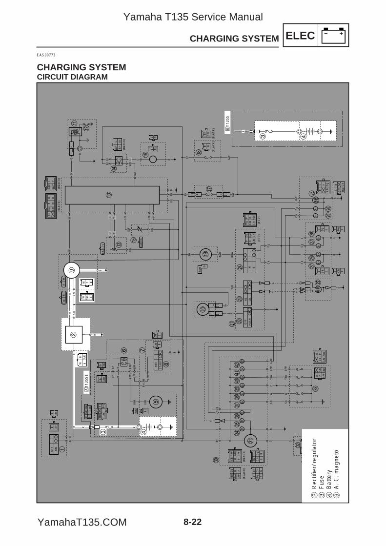
ELECCHARGING SYSTEM
8-22
EAS00773
CHARGING SYSTEMCIRCUIT DIAGRAM
R Br
WW
OF
F
ON
Br
R
R
OF
F
ST
AR
T
B
L/W
L/W
B
BS
bW
PY
/W
Y/W
L/W
L/W
Sb
WP
G G
LD
gC
hB
r
BG
RBr
Br
RBr
L/W
L/W
R/W
R/W
R/W
Y
Sb
Y/W
PL/
WW
L/W
G/W
G/W
Sb W
Y/W
P
Br
L Dg
GB
Ch
Dg B
Br
Ch
L
G
(BLA
CK
)
(BLA
CK
)(B
LAC
K)
(BLA
CK
)(B
LAC
K)
(BLA
CK
) (BLA
CK
)(B
LAC
K)
(BLA
CK
)
Y/W
L/WSb
Y/W
L/W
WW
Sb
PP
RR
B
WB
Br
Br
Br
L/Y
W
B
BB
R
R
OO
W Y/R B
Y BW
Br
L/W
Br
L/W
BBL/W
L/W
B/L
G/R
G/R
G/W
B
Br
G/Y
G/Y
G/Y
Br
Br/
W
Br/
W
Br/
W Br
Y/R
L N R
Ch
Dg
LG
/Y
P
B
YG G
YY
P
HI
LO
OF
F
PU
SH
Br/W Ch
BD
g
L/B
W/Y
Y
PB Y/R
Br/W
P
Ch
Dg (R
ED
)(R
ED
)
Br
BB
B
Ch
Dg
Ch
Dg BLL
B BL L
BL Y
Ch
Dg
G/Y Dg
BL
Ch
RW
WR
B/L
B/L
LY
G B
LP W
Br
B O
Y/R
Y/R
Y/R
WW
RR/W
BrR
BLBL
BB
R/W
R
L YY
L L
PL
Br
B/L
B/L
B/L
Br
G/W
Y/W
Y/W
G/R
G/R
G/W
B
B
Ch
Dg
Ch
Dg
LL
Br
Br
1
2
3 4
5
6 7
8
9
0
q
w
er
y
t
u
ip
o
a sd
f
gj
j
hh
kk
l
;
z
x
v
c
bn
m,
./
!@
R RR
3 4
åT
135S
E
∫T
135S
L/W
R Br
R/W
L/W
R Br
R/W
2R
ectif
ier/
reg
ulat
or3
Fus
e4
Bat
tery
9A
. C. m
agne
to
5YP-F8197-E0_8_1 05.6.27 19:27 Page 22
Yamaha T135 Service Manual
YamahaT135.COM
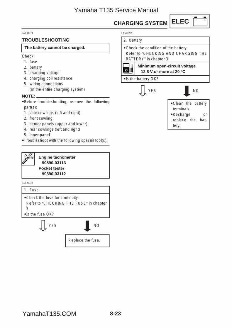
CHARGING SYSTEM ELEC
8-23
EAS00774
TROUBLESHOOTING
Check:1. fuse2. battery3. charging voltage4. charging coil resistance5. wiring connections
(of the entire charging system)
NOTE:9Before troubleshooting, remove the followingpart(s):1. side cowlings (left and right)2. front cowling3. center panels (upper and lower)4. rear cowlings (left and right)5. inner panel9Troubleshoot with the following special tool(s).
EAS00739
2. Battery
9Check the condition of the battery.Refer to “CHECKING AND CHARGING THEBATTERY” in chapter 3.
9Is the battery OK?
YES NO
9Clean the batteryterminals.9Recharge orreplace the bat-tery.
Engine tachometer90890-03113
Pocket tester90890-03112
Minimum open-circuit voltage12.8 V or more at 20 °C
EAS00738
1. Fuse
9Check the fuse for continuity.Refer to “CHECKING THE FUSE” in chapter3.9Is the fuse OK?
YES NO
Replace the fuse.
The battery cannot be charged.
5YP-F8197-E0_8_1 05.6.27 19:27 Page 23
Yamaha T135 Service Manual
YamahaT135.COM
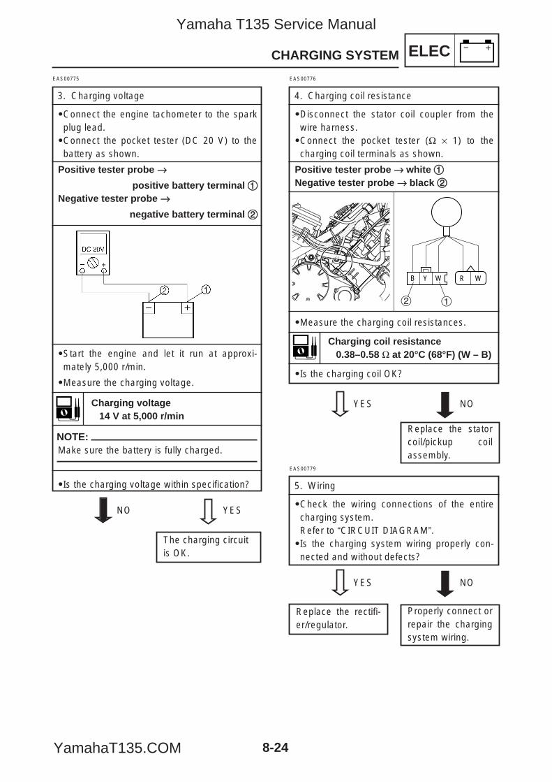
ELEC
8-24
CHARGING SYSTEM
EAS00775
3. Charging voltage
9Connect the engine tachometer to the sparkplug lead.9Connect the pocket tester (DC 20 V) to thebattery as shown.
Positive tester probe →→
positive battery terminal 11Negative tester probe →→
negative battery terminal 22
9Start the engine and let it run at approxi-mately 5,000 r/min.
9Measure the charging voltage.
NOTE:Make sure the battery is fully charged.
9Is the charging voltage within specification?
Charging voltage14 V at 5,000 r/min
The charging circuitis OK.
NO YES
EAS00776
4. Charging coil resistance
9Disconnect the stator coil coupler from thewire harness.9Connect the pocket tester (Ω × 1) to thecharging coil terminals as shown.
Positive tester probe →→ white 11Negative tester probe →→ black 22
9Measure the charging coil resistances.
9Is the charging coil OK?
YES NO
WB Y R W
12
EAS00779
5. Wiring
9Check the wiring connections of the entirecharging system.Refer to “CIRCUIT DIAGRAM”.9Is the charging system wiring properly con-nected and without defects?
YES NO
Properly connect orrepair the chargingsystem wiring.
Replace the statorcoil/pickup coilassembly.
Replace the rectifi-er/regulator.
Charging coil resistance0.38–0.58 Ω at 20°C (68°F) (W – B)
5YP-F8197-E0_8_1 05.6.27 19:27 Page 24
Yamaha T135 Service Manual
YamahaT135.COM
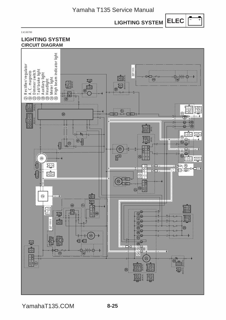
ELECLIGHTING SYSTEM
8-25
EAS00780
LIGHTING SYSTEMCIRCUIT DIAGRAM
R Br
WW
OF
F
ON
Br
R
R
OF
F
ST
AR
T
B
L/W
L/W
B
BS
bW
PY
/W
Y/W
L/W
L/W
Sb
WP
G G
LD
gC
hB
r
BG
RBr
Br
RBr
L/W
L/W
R/W
R/W
R/W
Y
Sb
Y/W
PL/
WW
L/W
G/W
G/W
Sb W
Y/W
P
Br
L Dg
GB
Ch
Dg B
Br
Ch
L
G
(BLA
CK
)
(BLA
CK
)(B
LAC
K)
(BLA
CK
)(B
LAC
K)
(BLA
CK
) (BLA
CK
)(B
LAC
K)
(BLA
CK
)
Y/W
L/WSb
Y/W
L/W
WW
Sb
PP
RR
B
WB
Br
Br
Br
L/Y
W
B
BB
R
R
OO
W Y/R B
Y BW
Br
L/W
Br
L/W
BBL/W
L/W
B/L
G/R
G/R
G/W
B
Br
G/Y
G/Y
G/Y
Br
Br/
W
Br/
W
Br/
W Br
Y/R
L N R
Ch
Dg
LG
/Y
P
B
YG G
YY
P
HI
LO
OF
F
PU
SH
Br/W Ch
BD
g
L/B
W/Y
Y
PB Y/R
Br/W
P
Ch
Dg (R
ED
)(R
ED
)
Br
BB
B
Ch
Dg
Ch
Dg BLL
B BL L
BL Y
Ch
Dg
G/Y Dg
BL
Ch
RW
WR
B/L
B/L
LY
G B
LP W
Br
B O
Y/R
Y/R
Y/R
WW
RR/W
BrR
BLBL
BB
R/W
R
L YY
L L
PL
Br
B/L
B/L
B/L
Br
G/W
Y/W
Y/W
G/R
G/R
G/W
B
B
Ch
Dg
Ch
Dg
LL
Br
Br
1
2
3 4
5
6 7
8
9
0
q
w
er
y
t
u
ip
o
a sd
f
gj
j
hh
kk
l
;
z
x
v
c
bn
m,
./
!@
R RR
3 4
åT
135S
E
∫T
135S
L/W
R Br
R/W
L/W
R Br
R/W
2R
ectif
ier/
reg
ulat
or9
A. C
. mag
neto
dD
imm
er s
witc
hg
Tai
l/ br
ake
light
kA
uxili
ary
light
lH
eadl
ight
vM
eter
ligh
tb
Hig
h be
am in
dica
tor
light
5YP-F8197-E0_8_1 05.6.27 19:27 Page 25
Yamaha T135 Service Manual
YamahaT135.COM
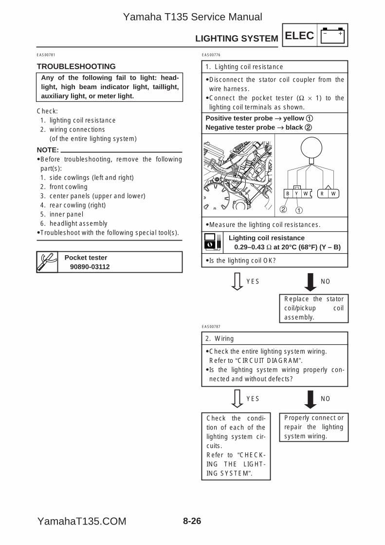
ELEC
8-26
LIGHTING SYSTEM
EAS00781
TROUBLESHOOTING
Check:1. lighting coil resistance2. wiring connections
(of the entire lighting system)
NOTE:9Before troubleshooting, remove the followingpart(s):1. side cowlings (left and right)2. front cowling3. center panels (upper and lower)4. rear cowling (right)5. inner panel6. headlight assembly9Troubleshoot with the following special tool(s).
Pocket tester90890-03112
Any of the following fail to light: head-light, high beam indicator light, taillight,auxiliary light, or meter light.
EAS00776
1. Lighting coil resistance
9Disconnect the stator coil coupler from thewire harness.9Connect the pocket tester (Ω × 1) to thelighting coil terminals as shown.
Positive tester probe →→ yellow 11Negative tester probe →→ black 22
9Measure the lighting coil resistances.
9Is the lighting coil OK?
YES NO
WB Y R W
12
EAS00787
2. Wiring
9Check the entire lighting system wiring.Refer to “CIRCUIT DIAGRAM”.9Is the lighting system wiring properly con-nected and without defects?
YES NO
Properly connect orrepair the lightingsystem wiring.
Replace the statorcoil/pickup coilassembly.
Check the condi-tion of each of thelighting system cir-cuits.Refer to “CHECK-ING THE LIGHT-ING SYSTEM”.
Lighting coil resistance0.29–0.43 Ω at 20°C (68°F) (Y – B)
5YP-F8197-E0_8_1 05.6.27 19:27 Page 26
Yamaha T135 Service Manual
YamahaT135.COM
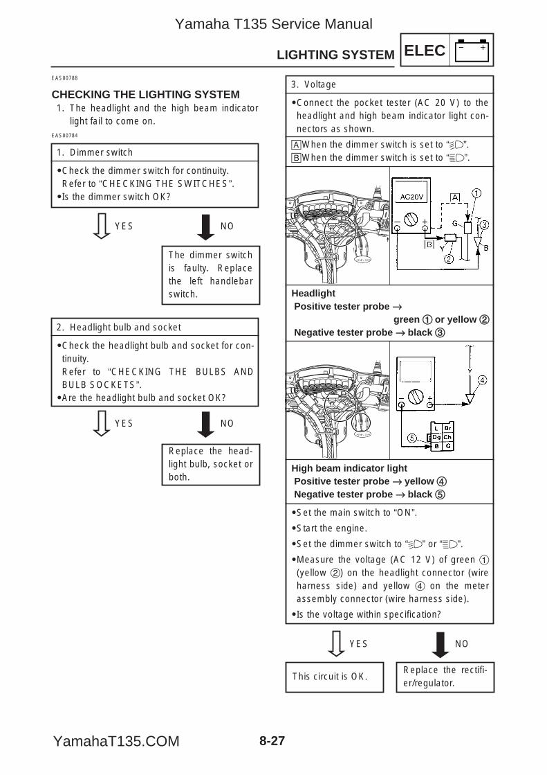
ELEC
8-27
LIGHTING SYSTEM
EAS00788
CHECKING THE LIGHTING SYSTEM1. The headlight and the high beam indicator
light fail to come on.
The dimmer switchis faulty. Replacethe left handlebarswitch.
EAS00784
1. Dimmer switch
9Check the dimmer switch for continuity.Refer to “CHECKING THE SWITCHES”.9Is the dimmer switch OK?
YES NO
2. Headlight bulb and socket
9Check the headlight bulb and socket for con-tinuity.Refer to “CHECKING THE BULBS ANDBULB SOCKETS”.9Are the headlight bulb and socket OK?
YES NO
Replace the head-light bulb, socket orboth.
3. Voltage
9Connect the pocket tester (AC 20 V) to theheadlight and high beam indicator light con-nectors as shown.
åWhen the dimmer switch is set to “%”.∫When the dimmer switch is set to “&”.
HeadlightPositive tester probe →→
green 11 or yellow 22Negative tester probe →→ black 33
High beam indicator lightPositive tester probe →→ yellow 44Negative tester probe →→ black 55
9Set the main switch to “ON”.
9Start the engine.
9Set the dimmer switch to “%” or “&”.
9Measure the voltage (AC 12 V) of green 1(yellow 2) on the headlight connector (wireharness side) and yellow 4 on the meterassembly connector (wire harness side).
9Is the voltage within specification?
YES NO
Replace the rectifi-er/regulator.
This circuit is OK.
5YP-F8197-E0_8_1 05.6.27 19:27 Page 27
Yamaha T135 Service Manual
YamahaT135.COM
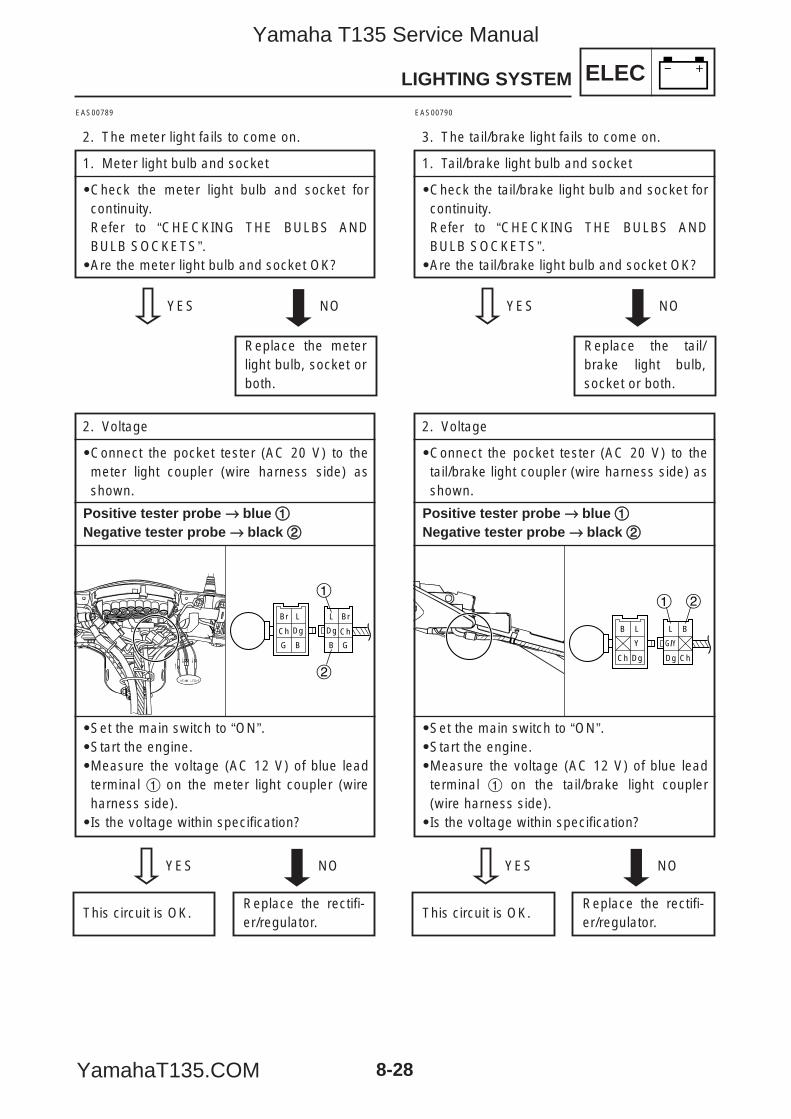
ELECLIGHTING SYSTEM
8-28
EAS00789
2. The meter light fails to come on.
1. Meter light bulb and socket
9Check the meter light bulb and socket forcontinuity.Refer to “CHECKING THE BULBS ANDBULB SOCKETS”.9Are the meter light bulb and socket OK?
YES NO
Replace the meterlight bulb, socket orboth.
EAS00790
3. The tail/brake light fails to come on.
1. Tail/brake light bulb and socket
9Check the tail/brake light bulb and socket forcontinuity.Refer to “CHECKING THE BULBS ANDBULB SOCKETS”.9Are the tail/brake light bulb and socket OK?
YES NO
Replace the tail/brake light bulb,socket or both.
2. Voltage
9Connect the pocket tester (AC 20 V) to themeter light coupler (wire harness side) asshown.
Positive tester probe →→ blue 11Negative tester probe →→ black 22
9Set the main switch to “ON”.9Start the engine.9Measure the voltage (AC 12 V) of blue leadterminal 1 on the meter light coupler (wireharness side).9Is the voltage within specification?
Br
G
Ch
L
B
Dg
L
B
Br
Dg
G
Ch
1
2
YES NO
Replace the rectifi-er/regulator.
This circuit is OK.
2. Voltage
9Connect the pocket tester (AC 20 V) to thetail/brake light coupler (wire harness side) asshown.
Positive tester probe →→ blue 11Negative tester probe →→ black 22
9Set the main switch to “ON”.9Start the engine.9Measure the voltage (AC 12 V) of blue leadterminal 1 on the tail/brake light coupler(wire harness side).9Is the voltage within specification?
B
Ch
L
Dg
Y
L
Dg
B
G/Y
Ch
1 2
YES NO
Replace the rectifi-er/regulator.
This circuit is OK.
5YP-F8197-E0_8_1 05.6.27 19:27 Page 28
Yamaha T135 Service Manual
YamahaT135.COM
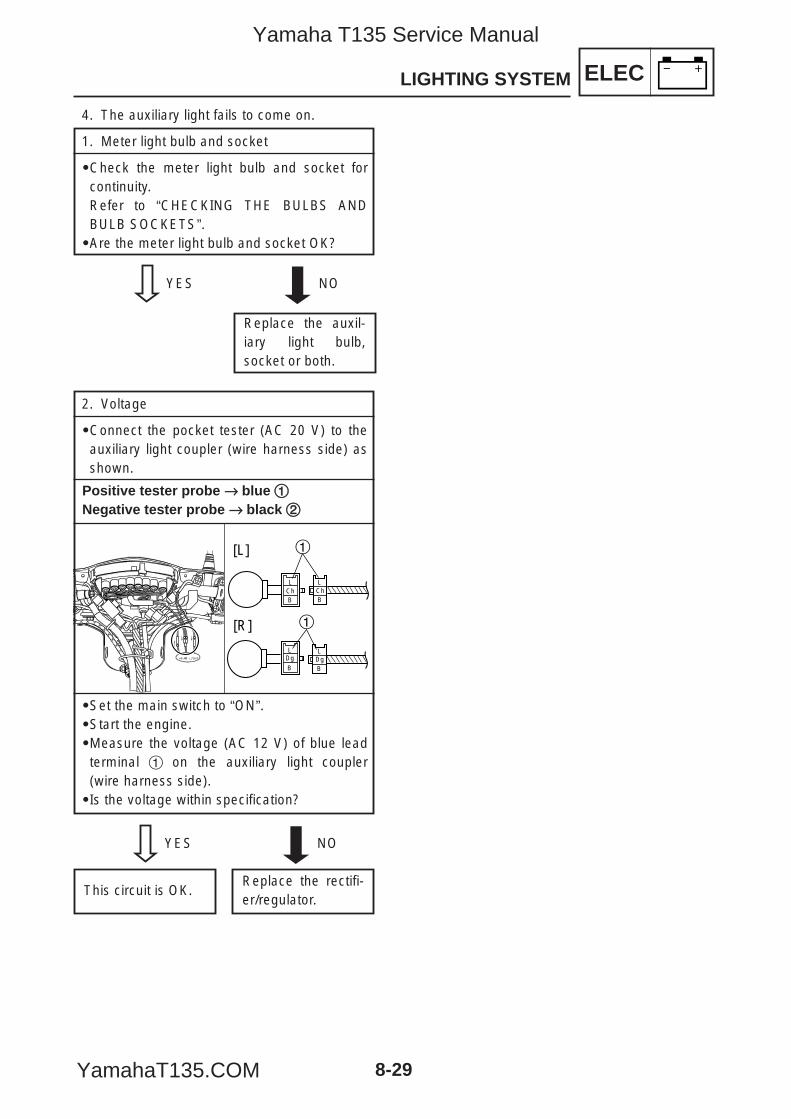
ELECLIGHTING SYSTEM
8-29
4. The auxiliary light fails to come on.
1. Meter light bulb and socket
9Check the meter light bulb and socket forcontinuity.Refer to “CHECKING THE BULBS ANDBULB SOCKETS”.9Are the meter light bulb and socket OK?
YES NO
Replace the auxil-iary light bulb,socket or both.
2. Voltage
9Connect the pocket tester (AC 20 V) to theauxiliary light coupler (wire harness side) asshown.
Positive tester probe →→ blue 11Negative tester probe →→ black 22
9Set the main switch to “ON”.9Start the engine.9Measure the voltage (AC 12 V) of blue leadterminal 1 on the auxiliary light coupler(wire harness side).9Is the voltage within specification?
BDgDg
B
LL
ChChB B
L L
1
1
[L]
[R]
YES NO
Replace the rectifi-er/regulator.
This circuit is OK.
5YP-F8197-E0_8_1 05.6.27 19:27 Page 29
Yamaha T135 Service Manual
YamahaT135.COM
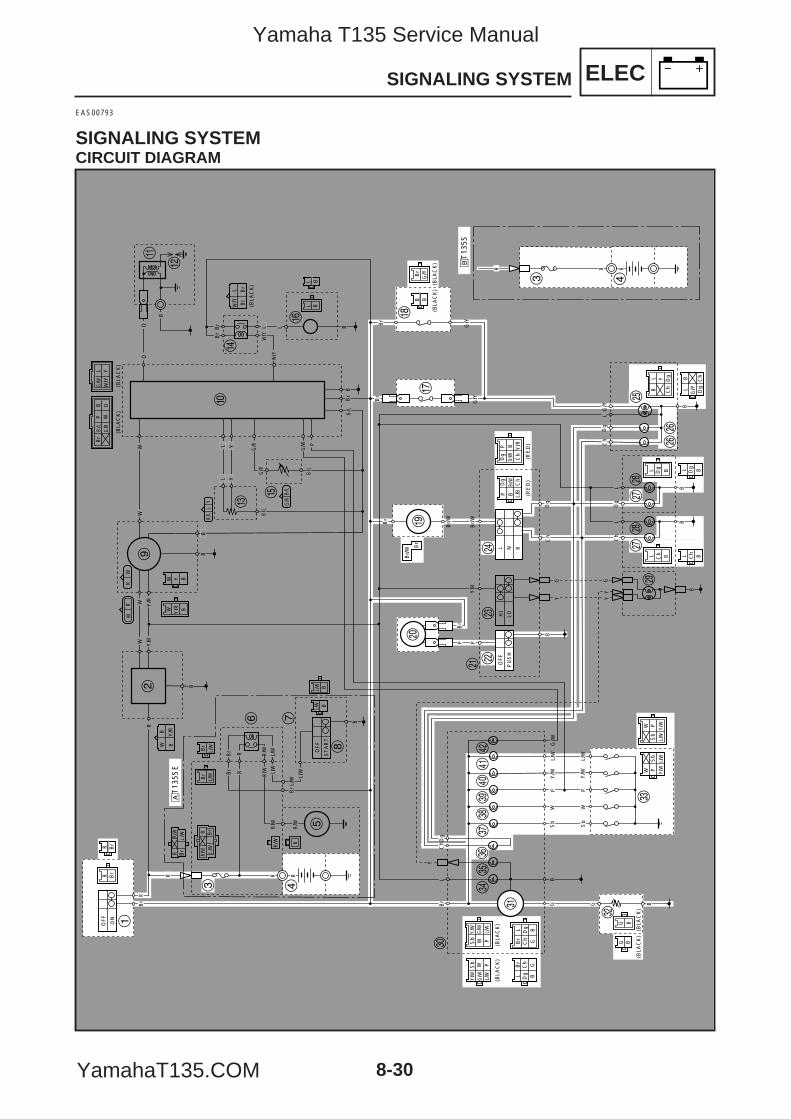
ELEC
8-30
SIGNALING SYSTEM
EAS00793
SIGNALING SYSTEMCIRCUIT DIAGRAM
R Br
WW
OF
F
ON
Br
R
R
OF
F
ST
AR
T
B
L/W
L/W
B
BS
bW
PY
/W
Y/W
L/W
L/W
Sb
WP
G G
LD
gC
hB
r
BG
RBr
Br
RBr
L/W
L/W
R/W
R/W
R/W
Y
Sb
Y/W
PL/
WW
L/W
G/W
G/W
Sb W
Y/W
P
Br
L Dg
GB
Ch
Dg B
Br
Ch
L
G
(BLA
CK
)
(BLA
CK
)(B
LAC
K)
(BLA
CK
)(B
LAC
K)
(BLA
CK
) (BLA
CK
)(B
LAC
K)
(BLA
CK
)
Y/W
L/WSb
Y/W
L/W
WW
Sb
PP
RR
B
WB
Br
Br
Br
L/Y
W
B
BB
R
R
OO
W Y/R B
Y BW
Br
L/W
Br
L/W
BBL/W
L/W
B/L
G/R
G/R
G/W
B
Br
G/Y
G/Y
G/Y
Br
Br/
W
Br/
W
Br/
W Br
Y/R
L N R
Ch
Dg
LG
/Y
P
B
YG G
YY
P
HI
LO
OF
F
PU
SH
Br/W Ch
BD
g
L/B
W/Y
Y
PB Y/R
Br/W
P
Ch
Dg (R
ED
)(R
ED
)
Br
BB
B
Ch
Dg
Ch
Dg BLL
B BL L
BL Y
Ch
Dg
G/Y Dg
BL
Ch
RW
WR
B/L
B/L
LY
G B
LP W
Br
B O
Y/R
Y/R
Y/R
WW
RR/W
BrR
BLBL
BB
R/W
R
L YY
L L
PL
Br
B/L
B/L
B/L
Br
G/W
Y/W
Y/W
G/R
G/R
G/W
B
B
Ch
Dg
Ch
Dg
LL
Br
Br
1
2
3 4
5
6 7
8
9
0
q
w
er
y
t
u
ip
o
a sd
f
gj
j
hh
kk
l
;
z
x
v
c
bn
m,
./
!@
RR
3 4
åT
135S
E
∫T
135S
R
L/W
R Br
R/W
L/W
R Br
R/W
5YP-F8197-E0_8_1 05.6.27 19:27 Page 30
Yamaha T135 Service Manual
YamahaT135.COM
ELEC
8-31
SIGNALING SYSTEM
1 Main switch3 Fuse4 Batteryu Front brake light switchi Rear brake light switcho Turn signal relayp Horns Horn switchf Turn signal switchg Tail/brake lighth Rear turn signal lightj Front turn signal lightz Fuel gaugex Fuel senderc Neutral switchn Turn signal indicator lightm Neutral indicator light, 1st gear position indicator light. 2nd gear position indicator light/ 3rd gear position indicator light! 4th gear position indicator light
5YP-F8197-E0_8_1 05.6.27 19:27 Page 31
Yamaha T135 Service Manual
YamahaT135.COM
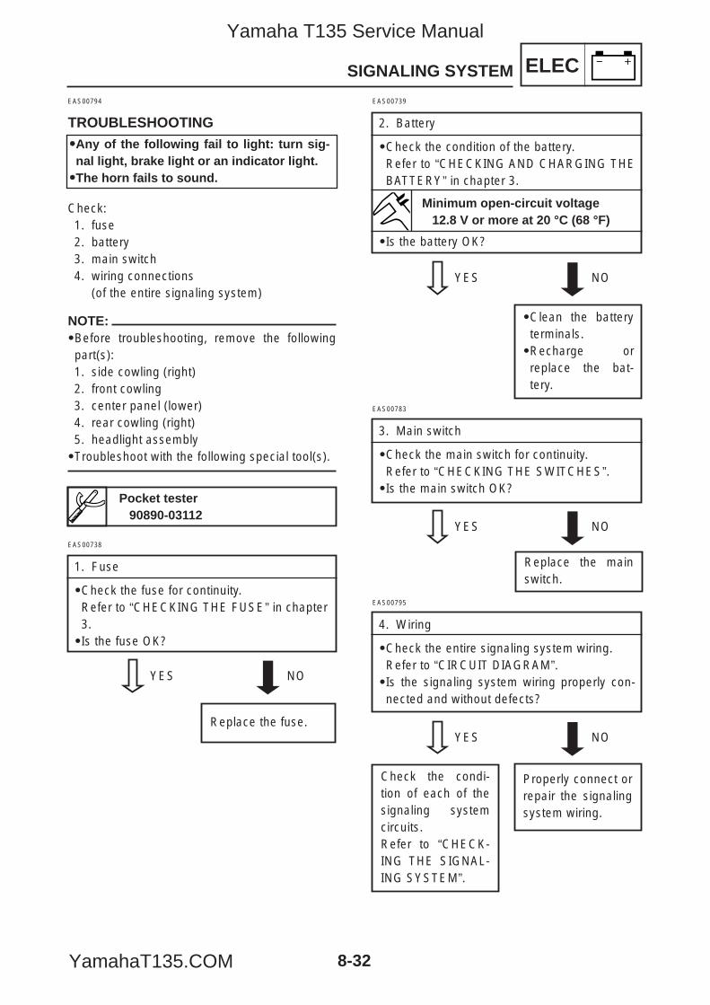
ELEC
8-32
SIGNALING SYSTEM
NOTE:9Before troubleshooting, remove the followingpart(s):1. side cowling (right)2. front cowling3. center panel (lower)4. rear cowling (right)5. headlight assembly9Troubleshoot with the following special tool(s).
EAS00794
TROUBLESHOOTING
Check:1. fuse2. battery3. main switch4. wiring connections
(of the entire signaling system)
EAS00738
1. Fuse
9Check the fuse for continuity.Refer to “CHECKING THE FUSE” in chapter3.9Is the fuse OK?
YES NO
Replace the fuse.
EAS00739
2. Battery
9Check the condition of the battery.Refer to “CHECKING AND CHARGING THEBATTERY” in chapter 3.
9Is the battery OK?
YES NO
9Clean the batteryterminals.9Recharge orreplace the bat-tery.
Pocket tester90890-03112
Minimum open-circuit voltage12.8 V or more at 20 °C (68 °F)
99Any of the following fail to light: turn sig-nal light, brake light or an indicator light.99The horn fails to sound.
Replace the mainswitch.
EAS00783
3. Main switch
9Check the main switch for continuity.Refer to “CHECKING THE SWITCHES”.9Is the main switch OK?
YES NO
EAS00795
4. Wiring
9Check the entire signaling system wiring.Refer to “CIRCUIT DIAGRAM”.9Is the signaling system wiring properly con-nected and without defects?
YES NO
Properly connect orrepair the signalingsystem wiring.
Check the condi-tion of each of thesignaling systemcircuits.Refer to “CHECK-ING THE SIGNAL-ING SYSTEM”.
5YP-F8197-E0_8_1 05.6.27 19:27 Page 32
Yamaha T135 Service Manual
YamahaT135.COM
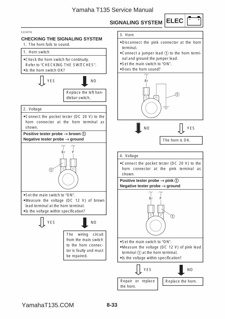
ELEC
8-33
4. Voltage
9Connect the pocket tester (DC 20 V) to thehorn connector at the pink terminal asshown.
Positive tester probe →→ pink 11Negative tester probe →→ ground
9Set the main switch to “ON”.9Measure the voltage (DC 12 V) of pink leadterminal 1 at the horn terminal.9Is the voltage within specification?
YES NO
Replace the horn.Repair or replacethe horn.
1
Br P
SIGNALING SYSTEM
EAS00796
CHECKING THE SIGNALING SYSTEM1. The horn fails to sound.
1. Horn switch
9Check the horn switch for continuity.Refer to “CHECKING THE SWITCHES”.9Is the horn switch OK?
YES NO
Replace the left han-dlebar switch.
2. Voltage
9Connect the pocket tester (DC 20 V) to thehorn connector at the horn terminal asshown.
Positive tester probe →→ brown 11Negative tester probe →→ ground
9Set the main switch to “ON”.9Measure the voltage (DC 12 V) of brownlead terminal at the horn terminal.9Is the voltage within specification?
YES NO
The wiring circuitfrom the main switchto the horn connec-tor is faulty and mustbe repaired.
3. Horn
9Disconnect the pink connector at the hornterminal.9Connect a jumper lead 1 to the horn termi-nal and ground the jumper lead.9Set the main switch to “ON”.9Does the horn sound?
NO YES
The horn is OK.
Br P
1
1
Br
5YP-F8197-E0_8_1 05.6.27 19:27 Page 33
Yamaha T135 Service Manual
YamahaT135.COM
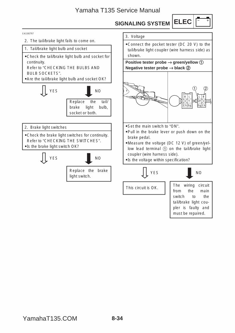
ELEC
8-34
SIGNALING SYSTEM
EAS00797
2. The tail/brake light fails to come on.
1. Tail/brake light bulb and socket
9Check the tail/brake light bulb and socket forcontinuity.Refer to “CHECKING THE BULBS ANDBULB SOCKETS”.9Are the tail/brake light bulb and socket OK?
3. Voltage
9Connect the pocket tester (DC 20 V) to thetail/brake light coupler (wire harness side) asshown.
Positive tester probe →→ green/yellow 11Negative tester probe →→ black 22
9Set the main switch to “ON”.9Pull in the brake lever or push down on thebrake pedal.9Measure the voltage (DC 12 V) of green/yel-low lead terminal 1 on the tail/brake lightcoupler (wire harness side).9Is the voltage within specification?
2. Brake light switches
9Check the brake light switches for continuity.Refer to “CHECKING THE SWITCHES”.9Is the brake light switch OK?
YES NO
Replace the tail/brake light bulb,socket or both.
YES NO
Replace the brakelight switch.
YES NO
The wiring circuitfrom the mainswitch to thetail/brake light cou-pler is faulty andmust be repaired.
This circuit is OK.
B
Ch
L
Dg
Y
L
Dg
B
G/Y
Ch
1 2
5YP-F8197-E0_8_1 05.6.27 19:27 Page 34
Yamaha T135 Service Manual
YamahaT135.COM
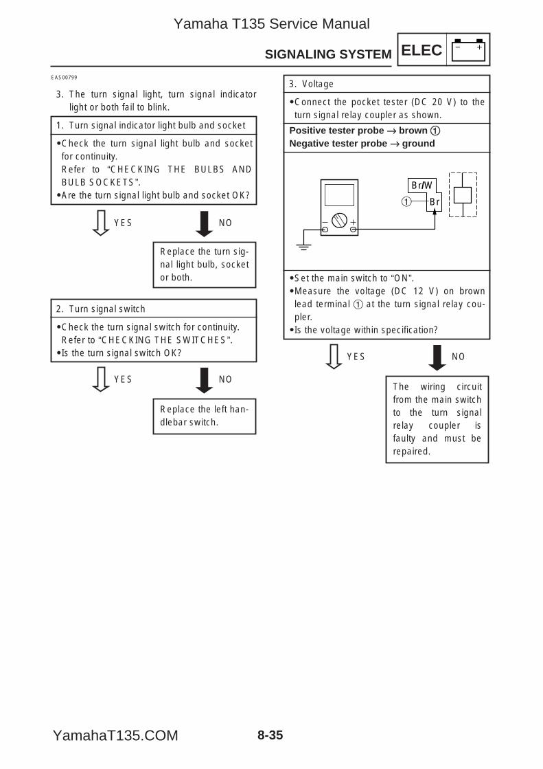
ELEC
8-35
SIGNALING SYSTEM
EAS00799
3. The turn signal light, turn signal indicatorlight or both fail to blink.
1. Turn signal indicator light bulb and socket
9Check the turn signal light bulb and socketfor continuity.Refer to “CHECKING THE BULBS ANDBULB SOCKETS”.9Are the turn signal light bulb and socket OK?
2. Turn signal switch
9Check the turn signal switch for continuity.Refer to “CHECKING THE SWITCHES”.9Is the turn signal switch OK?
YES NO
Replace the turn sig-nal light bulb, socketor both.
YES NO
Replace the left han-dlebar switch.
3. Voltage
9Connect the pocket tester (DC 20 V) to theturn signal relay coupler as shown.
Positive tester probe →→ brown 11Negative tester probe →→ ground
9Set the main switch to “ON”.9Measure the voltage (DC 12 V) on brownlead terminal 1 at the turn signal relay cou-pler.9Is the voltage within specification?
YES NO
The wiring circuitfrom the main switchto the turn signalrelay coupler isfaulty and must berepaired.
Br/W
Br1
5YP-F8197-E0_8_1 05.6.27 19:27 Page 35
Yamaha T135 Service Manual
YamahaT135.COM
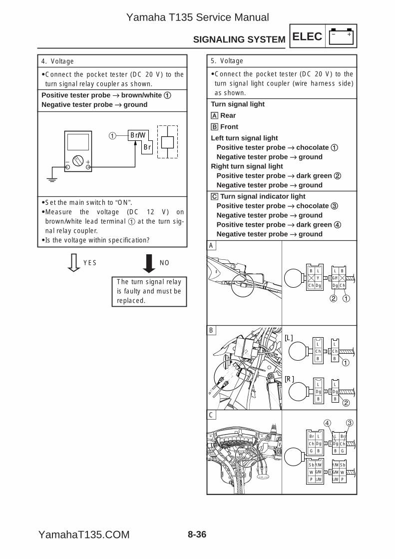
ELEC
8-36
SIGNALING SYSTEM
5. Voltage
9Connect the pocket tester (DC 20 V) to theturn signal light coupler (wire harness side)as shown.
Turn signal light
åå Rear
∫∫ Front
Left turn signal lightPositive tester probe →→ chocolate 11Negative tester probe →→ ground
Right turn signal lightPositive tester probe →→ dark green 22Negative tester probe →→ ground
çç Turn signal indicator lightPositive tester probe →→ chocolate 33Negative tester probe →→ groundPositive tester probe →→ dark green 44Negative tester probe →→ ground
B
Ch
L
Dg
Y
L
Dg
B
G/Y
Ch
2 1
4. Voltage
9Connect the pocket tester (DC 20 V) to theturn signal relay coupler as shown.
Positive tester probe →→ brown/white 11Negative tester probe →→ ground
9Set the main switch to “ON”.9Measure the voltage (DC 12 V) onbrown/white lead terminal 1 at the turn sig-nal relay coupler.9Is the voltage within specification?
YES NO
The turn signal relayis faulty and must bereplaced.
Br/W
Br
1
A
L
B
Ch
L
B
Ch
1
L
B
Dg
L
B
Dg
2
[L]
[R]
B
L
B
Br
Dg
G
Ch
Sb
P
W
Y/W
L/W
Y/W
L/W
Sb
P
W
Br
G
Ch
L
B
Dg
4 3
G/W G/W
C
5YP-F8197-E0_8_1 05.6.27 19:28 Page 36
Yamaha T135 Service Manual
YamahaT135.COM
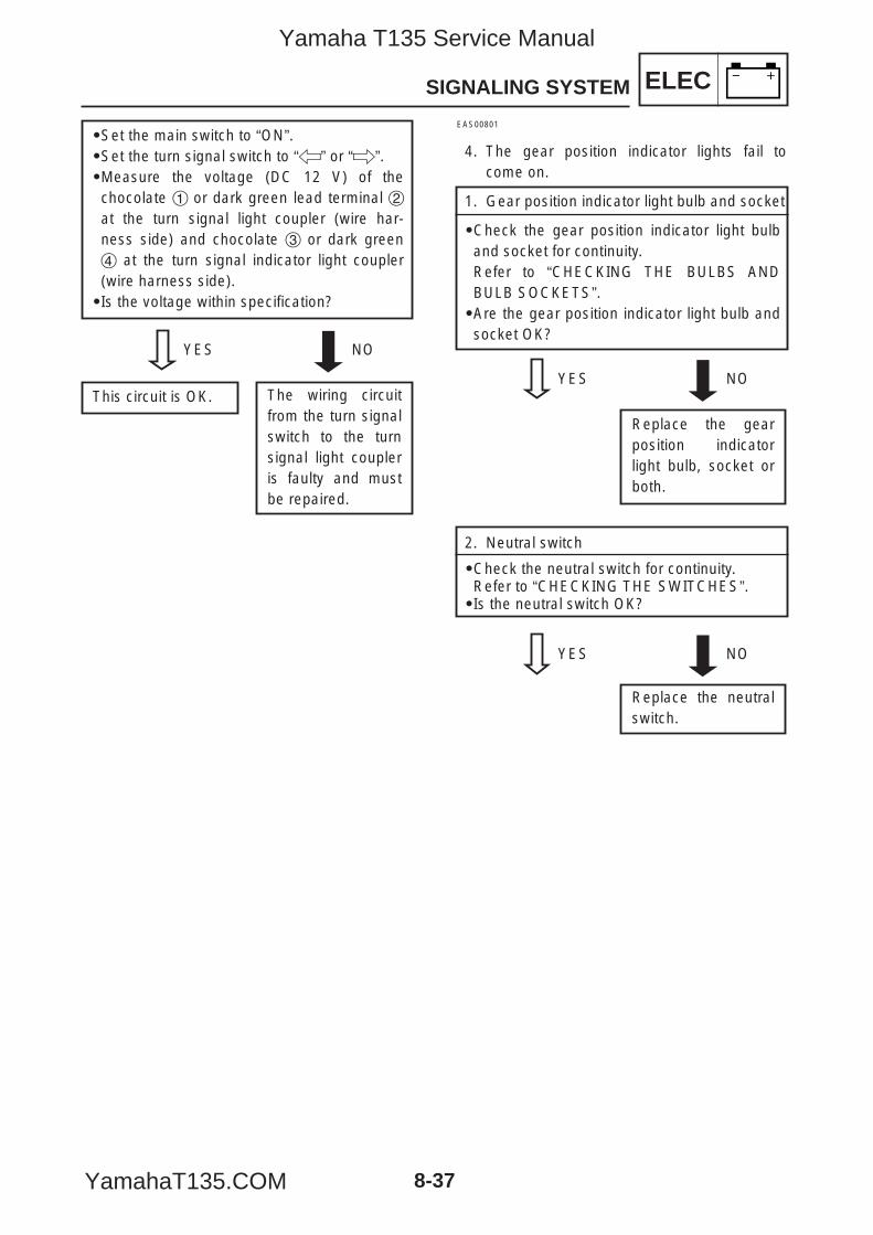
ELEC
8-37
SIGNALING SYSTEM
EAS00801
4. The gear position indicator lights fail tocome on.
1. Gear position indicator light bulb and socket
9Check the gear position indicator light bulband socket for continuity.Refer to “CHECKING THE BULBS ANDBULB SOCKETS”.9Are the gear position indicator light bulb andsocket OK?
YES NO
Replace the gearposition indicatorlight bulb, socket orboth.
2. Neutral switch
9Check the neutral switch for continuity.Refer to “CHECKING THE SWITCHES”.9Is the neutral switch OK?
YES NO
Replace the neutralswitch.
YES NO
This circuit is OK. The wiring circuitfrom the turn signalswitch to the turnsignal light coupleris faulty and mustbe repaired.
9Set the main switch to “ON”.9Set the turn signal switch to “4” or “6”.9Measure the voltage (DC 12 V) of thechocolate 1 or dark green lead terminal 2at the turn signal light coupler (wire har-ness side) and chocolate 3 or dark green4 at the turn signal indicator light coupler(wire harness side).9Is the voltage within specification?
5YP-F8197-E0_8_1 05.6.27 19:28 Page 37
Yamaha T135 Service Manual
YamahaT135.COM
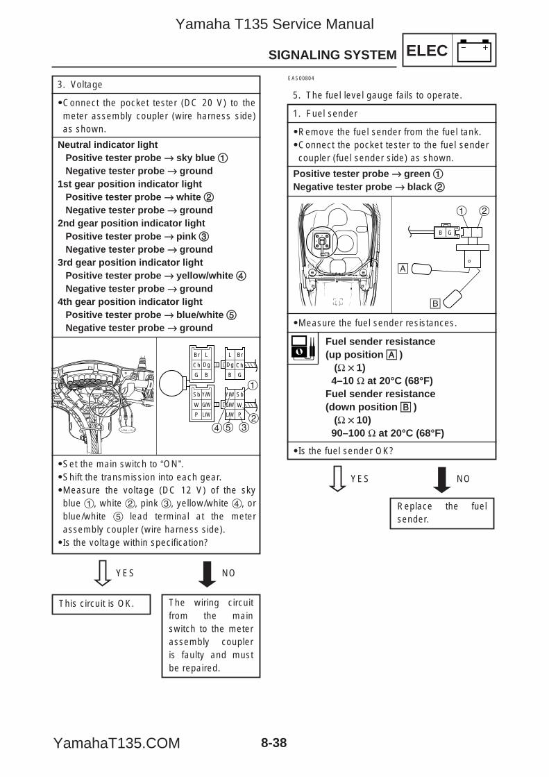
L
B
Br
Dg
G
Ch
Sb
P
W
Y/W
L/W
Y/W
L/W
Sb
P
W
Br
G
Ch
L
B
Dg
1
2354
G/W G/W
3. Voltage
9Connect the pocket tester (DC 20 V) to themeter assembly coupler (wire harness side)as shown.
Neutral indicator lightPositive tester probe →→ sky blue 11Negative tester probe →→ ground
1st gear position indicator lightPositive tester probe →→ white 22Negative tester probe →→ ground
2nd gear position indicator lightPositive tester probe →→ pink 33Negative tester probe →→ ground
3rd gear position indicator lightPositive tester probe →→ yellow/white 44Negative tester probe →→ ground
4th gear position indicator lightPositive tester probe →→ blue/white 55Negative tester probe →→ ground
9Set the main switch to “ON”.9Shift the transmission into each gear.9Measure the voltage (DC 12 V) of the skyblue 1, white 2, pink 3, yellow/white 4, orblue/white 5 lead terminal at the meterassembly coupler (wire harness side).9Is the voltage within specification?
ELEC
8-38
SIGNALING SYSTEM
YES NO
This circuit is OK. The wiring circuitfrom the mainswitch to the meterassembly coupleris faulty and mustbe repaired.
EAS00804
5. The fuel level gauge fails to operate.
1. Fuel sender
9Remove the fuel sender from the fuel tank.9Connect the pocket tester to the fuel sendercoupler (fuel sender side) as shown.
Positive tester probe →→ green 11Negative tester probe →→ black 22
9Measure the fuel sender resistances.
9Is the fuel sender OK?
1 2
å
∫
B G
Fuel sender resistance(up position åå )
(Ω ×× 1)4–10 Ω at 20°C (68°F)
Fuel sender resistance(down position ∫∫ )
(Ω ×× 10)90–100 Ω at 20°C (68°F)
YES NO
Replace the fuelsender.
5YP-F8197-E0_8_1 05.6.27 19:28 Page 38
Yamaha T135 Service Manual
YamahaT135.COM
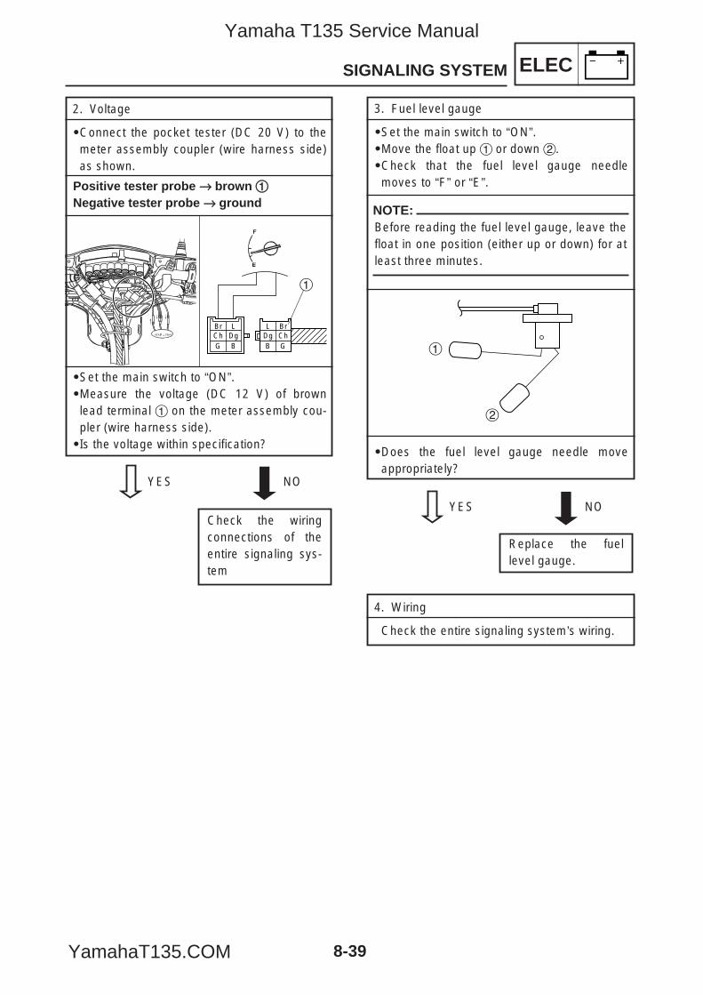
2. Voltage
9Connect the pocket tester (DC 20 V) to themeter assembly coupler (wire harness side)as shown.
Positive tester probe →→ brown 11Negative tester probe →→ ground
9Set the main switch to “ON”.9Measure the voltage (DC 12 V) of brownlead terminal 1 on the meter assembly cou-pler (wire harness side).9Is the voltage within specification?
Br LDg
G BCh Dg
B
BrCh
L
G
1
ELEC
8-39
SIGNALING SYSTEM
YES NO
Check the wiringconnections of theentire signaling sys-tem
YES NO
Replace the fuellevel gauge.
3. Fuel level gauge
9Set the main switch to “ON”.9Move the float up 1 or down 2.9Check that the fuel level gauge needlemoves to “F” or “E”.
NOTE:Before reading the fuel level gauge, leave thefloat in one position (either up or down) for atleast three minutes.
9Does the fuel level gauge needle moveappropriately?
1
2
4. Wiring
Check the entire signaling system’s wiring.
5YP-F8197-E0_8_1 05.6.27 19:28 Page 39
Yamaha T135 Service Manual
YamahaT135.COM
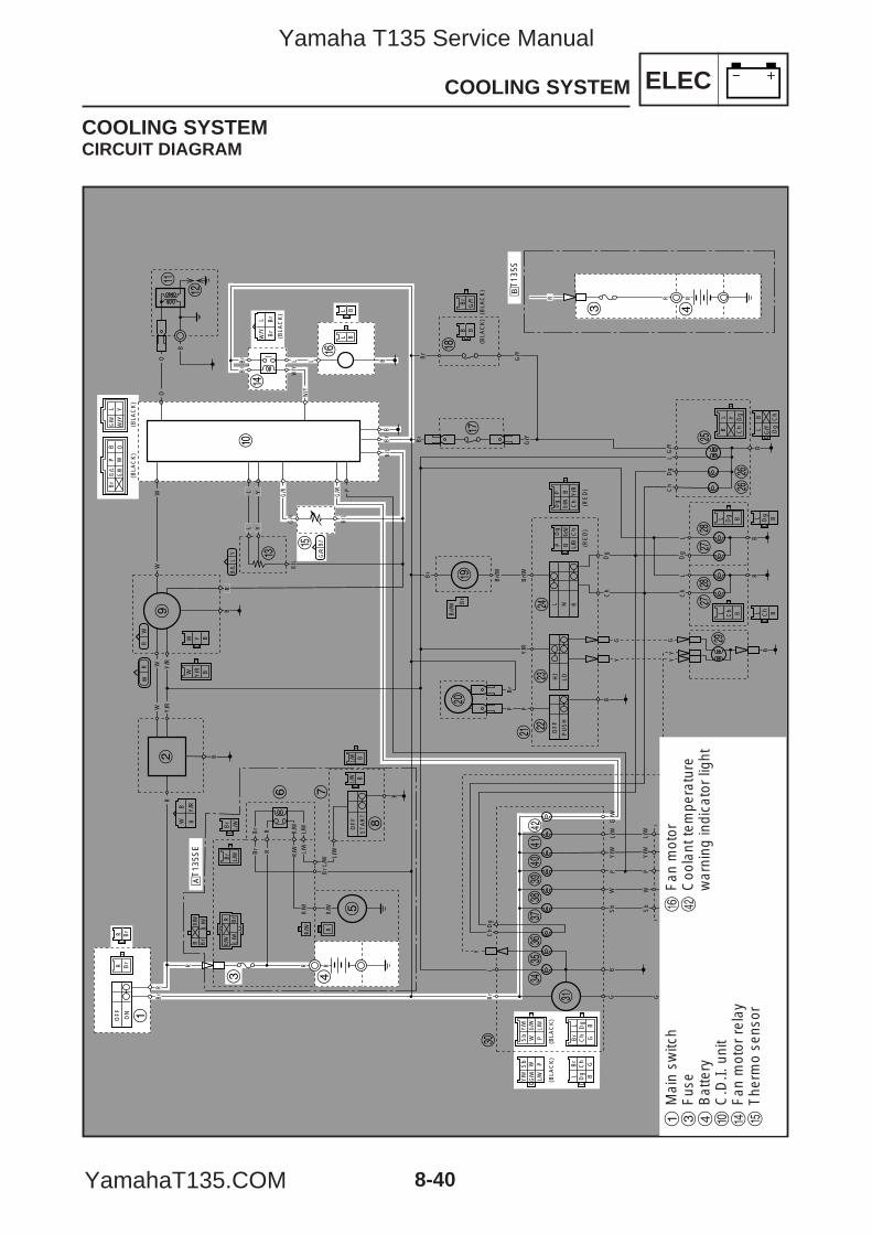
ELECCOOLING SYSTEM
8-40
COOLING SYSTEMCIRCUIT DIAGRAM
R Br
WW
OF
F
ON
Br
R
R
OF
F
ST
AR
T
B
L/W
L/W
B
BS
bW
PY
/W
Y/W
L/W
L/W
Sb
WP
G G
LD
gC
hB
r
BG
RBr
Br
RBr
L/W
L/W
R/W
R/W
R/W
Y
Sb
Y/W
PL/
WW
L/W
G/W
G/W
Sb W
Y/W
P
Br
L Dg
GB
Ch
Dg B
Br
Ch
L
G
(BLA
CK
)
(BLA
CK
)(B
LAC
K)
(BLA
CK
)(B
LAC
K)
(BLA
CK
) (BLA
CK
)(B
LAC
K)
(BLA
CK
)
Y/W
L/WSb
Y/W
L/W
WW
Sb
PP
RR
B
WB
Br
Br
Br
L/Y
W
B
BB
R
R
OO
W Y/R B
Y BW
Br
L/W
Br
L/W
BBL/W
L/W
B/L
G/R
G/R
G/W
B
Br
G/Y
G/Y
G/Y
Br
Br/
W
Br/
W
Br/
W Br
Y/R
L N R
Ch
Dg
LG
/Y
P
B
YG G
YY
P
HI
LO
OF
F
PU
SH
Br/W Ch
BD
g
L/B
W/Y
Y
PB Y/R
Br/W
P
Ch
Dg (R
ED
)(R
ED
)
Br
BB
B
Ch
Dg
Ch
Dg BLL
B BL L
BL Y
Ch
Dg
G/Y Dg
BL
Ch
RW
WR
B/L
B/
LY
G B
LP W
Br
B O
Y/R
Y/R
Y/R
WW
RR/W
BrR
BLBL
BB
R/W
R
L YY
L L
PL
Br
B/L
LB
/
B/L
Br
G/W
Y/W
Y/W
G/R
G/R
G/W
B
B
Ch
Dg
Ch
Dg
LL
Br
Br
1
2
3 4
5
6 7
8
9
0
q
w
er
y
t
u
ip
o
a sd
f
gj
j
hh
kk
l
;
z
x
v
c
bn
m,
./
!@
R RR
3 4
åT
135S
E
∫T
135S
L/W
R Br
R/W
L/W
R Br
R/W
1M
ain
switc
h3
Fus
e4
Bat
tery
0C
.D.I.
uni
tr
Fan
mot
or r
elay
tT
herm
o se
nsor
yF
an m
otor
@C
oola
nt te
mpe
ratu
rew
arni
ng in
dica
tor
light
5YP-F8197-E0_8_1 05.6.27 19:28 Page 40
Yamaha T135 Service Manual
YamahaT135.COM
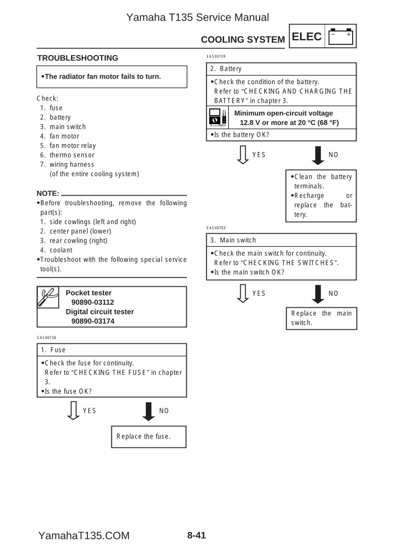
ELECCOOLING SYSTEM
8-41
NOTE:9Before troubleshooting, remove the followingpart(s):1. side cowlings (left and right)2. center panel (lower)3. rear cowling (right)4. coolant9Troubleshoot with the following special servicetool(s).
TROUBLESHOOTING
Check:1. fuse2. battery3. main switch4. fan motor5. fan motor relay6. thermo sensor7. wiring harness
(of the entire cooling system)
EAS00738
1. Fuse
9Check the fuse for continuity.Refer to “CHECKING THE FUSE” in chapter3.9Is the fuse OK?
YES NO
Replace the fuse.
EAS00739
2. Battery
9Check the condition of the battery.Refer to “CHECKING AND CHARGING THEBATTERY” in chapter 3.
9Is the battery OK?
YES NO
9Clean the batteryterminals.9Recharge orreplace the bat-tery.
Pocket tester90890-03112
Digital circuit tester90890-03174
Minimum open-circuit voltage12.8 V or more at 20 °C (68 °F)
9The radiator fan motor fails to turn.
Replace the mainswitch.
EAS00783
3. Main switch
9Check the main switch for continuity.Refer to “CHECKING THE SWITCHES”.9Is the main switch OK?
YES NO
5YP-F8197-E0_8_1 05.6.27 19:28 Page 41
Yamaha T135 Service Manual
YamahaT135.COM
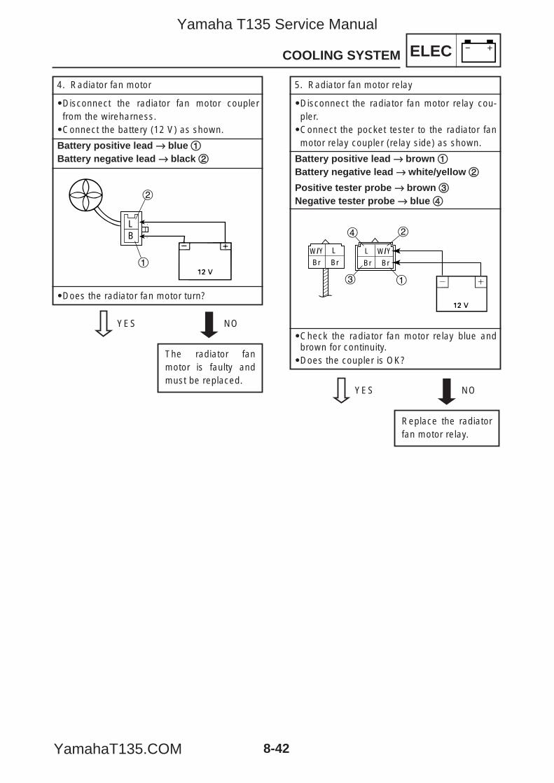
ELECCOOLING SYSTEM
8-42
4. Radiator fan motor
9Disconnect the radiator fan motor couplerfrom the wireharness.9Connect the battery (12 V) as shown.
Battery positive lead →→ blue 11Battery negative lead →→ black 22
9Does the radiator fan motor turn?
YES NO
The radiator fanmotor is faulty andmust be replaced.
BL
2
1
5. Radiator fan motor relay
9Disconnect the radiator fan motor relay cou-pler.9Connect the pocket tester to the radiator fanmotor relay coupler (relay side) as shown.
Battery positive lead →→ brown 11Battery negative lead →→ white/yellow 22
Positive tester probe →→ brown 33Negative tester probe →→ blue 44
9Check the radiator fan motor relay blue andbrown for continuity.9Does the coupler is OK?
YES NO
Replace the radiatorfan motor relay.
BrBr
L/YW
Br Br
L /YW
1
24
3
5YP-F8197-E0_8_1 05.6.27 19:28 Page 42
Yamaha T135 Service Manual
YamahaT135.COM
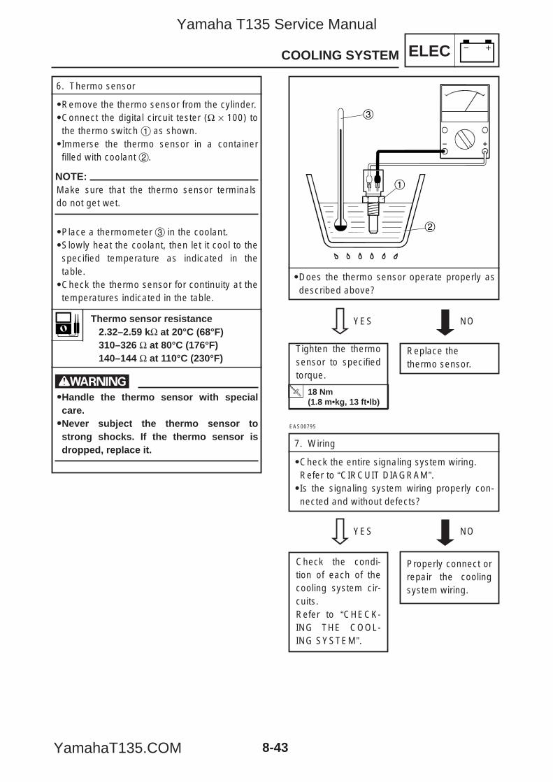
ELECCOOLING SYSTEM
8-43
6. Thermo sensor
9Remove the thermo sensor from the cylinder.9Connect the digital circuit tester (Ω × 100) tothe thermo switch 1 as shown.9Immerse the thermo sensor in a containerfilled with coolant 2.
NOTE:Make sure that the thermo sensor terminalsdo not get wet.
9Place a thermometer 3 in the coolant.9Slowly heat the coolant, then let it cool to thespecified temperature as indicated in thetable.9Check the thermo sensor for continuity at thetemperatures indicated in the table.
w99Handle the thermo sensor with specialcare.99Never subject the thermo sensor tostrong shocks. If the thermo sensor isdropped, replace it.
9Does the thermo sensor operate properly asdescribed above?
1
3
2
YES NO
Replace the thermo sensor.
Tighten the thermosensor to specifiedtorque.
EAS00795
7. Wiring
9Check the entire signaling system wiring.Refer to “CIRCUIT DIAGRAM”.9Is the signaling system wiring properly con-nected and without defects?
YES NO
Properly connect orrepair the coolingsystem wiring.
Check the condi-tion of each of thecooling system cir-cuits.Refer to “CHECK-ING THE COOL-ING SYSTEM”.
Thermo sensor resistance2.32–2.59 kΩ at 20°C (68°F)310–326 Ω at 80°C (176°F)140–144 Ω at 110°C (230°F)
18 Nm (1.8 m•kg, 13 ft•lb)
5YP-F8197-E0_8_1 05.6.27 19:28 Page 43
Yamaha T135 Service Manual
YamahaT135.COM
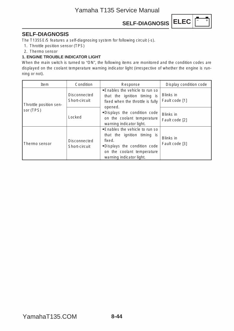
ELECSELF-DIAGNOSIS
8-44
SELF-DIAGNOSISThe T135SE/S features a self-diagnosing system for following circuit (-s).1. Throttle position sensor (TPS)2. Thermo sensor
1. ENGINE TROUBLE INDICATOR LIGHTWhen the main switch is turned to “ON”, the following items are monitored and the condition codes aredisplayed on the coolant temperature warning indicator light (irrespective of whether the engine is run-ning or not).
Item Condition Response Display condition code 9Enables the vehicle to run sothat the ignition timing isfixed when the throttle is fullyopened.9Displays the condition codeon the coolant temperaturewarning indicator light.9Enables the vehicle to run sothat the ignition timing isfixed.9Displays the condition codeon the coolant temperaturewarning indicator light.
Throttle position sen-sor (TPS)
Thermo sensor
DisconnectedShort-circuit
Blinks inFault code [1]
Blinks inFault code [2]
Locked
Disconnected Short-circuit
Blinks inFault code [3]
5YP-F8197-E0_8_1 05.6.27 19:28 Page 44
Yamaha T135 Service Manual
YamahaT135.COM
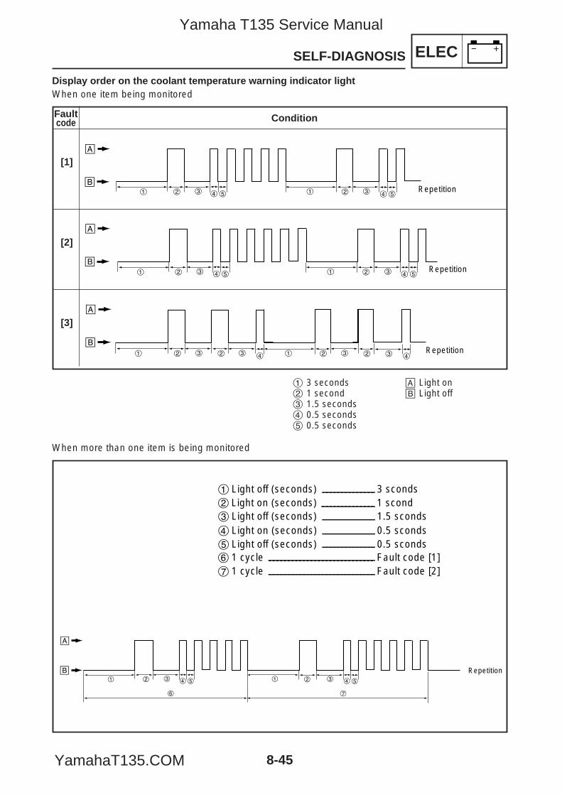
ELECSELF-DIAGNOSIS
8-45
Display order on the coolant temperature warning indicator lightWhen one item being monitored
Condition
[1]
[2]
[3]
2 3 4 5 1 2 3
å
∫Repetition1 4 5
2 3 4 5 1 2 3
å
∫Repetition1 4 5
2 3 2 3 4 1 2 3 2
å
∫Repetition1 3 4
1 3 seconds2 1 second3 1.5 seconds4 0.5 seconds5 0.5 seconds
å Light on∫ Light off
When more than one item is being monitored
2 3 4 5 1
å
∫ Repetition2 3 4 5
2 Light on (seconds) 1 scond 3 Light off (seconds) 1.5 sconds4 Light on (seconds) 0.5 sconds5 Light off (seconds) 0.5 sconds6 1 cycle Fault code [1] 7 1 cycle Fault code [2]
1
1 Light off (seconds) 3 sconds
76
Faultcode
5YP-F8197-E0_8_1 05.6.27 19:28 Page 45
Yamaha T135 Service Manual
YamahaT135.COM
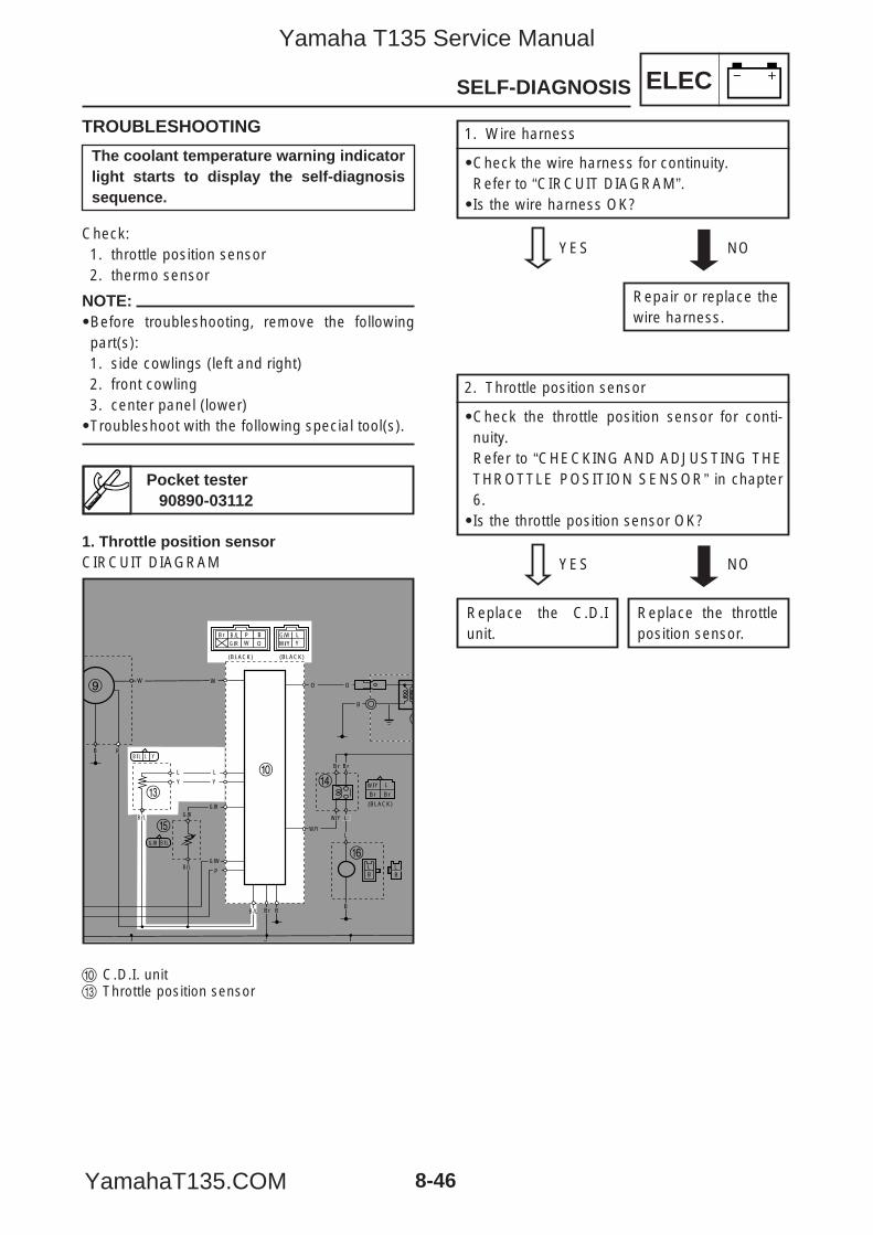
ELECSELF-DIAGNOSIS
8-46
TROUBLESHOOTING
Check:1. throttle position sensor2. thermo sensor
NOTE:9Before troubleshooting, remove the followingpart(s):1. side cowlings (left and right)2. front cowling3. center panel (lower)9Troubleshoot with the following special tool(s).
1. Wire harness
9Check the wire harness for continuity.Refer to “CIRCUIT DIAGRAM”.9Is the wire harness OK?
YES NO
Repair or replace thewire harness.
Pocket tester90890-03112
The coolant temperature warning indicatorlight starts to display the self-diagnosissequence.
1. Throttle position sensorCIRCUIT DIAGRAM
0 C.D.I. unite Throttle position sensor
(BLACK)(BLACK)
(BLACK)
BrBr
L/YW
B
BB
O O
B /LG /R
G /R
G /W
B
W/Y Y
B /L
B /L
L Y
LPW
Br BO
W W
BL
BL
R
L
Y Y
L
L
P
L
Br
B /L
B /L
B /L Br
G /W
Y/W
Y/W
G /RG /R
BrBr
9
0
w
er
y
t
2. Throttle position sensor
9Check the throttle position sensor for conti-nuity.Refer to “CHECKING AND ADJUSTING THETHROTTLE POSITION SENSOR” in chapter6.9Is the throttle position sensor OK?
YES NO
Replace the throttleposition sensor.
Replace the C.D.Iunit.
5YP-F8197-E0_8_1 05.6.27 19:28 Page 46
Yamaha T135 Service Manual
YamahaT135.COM
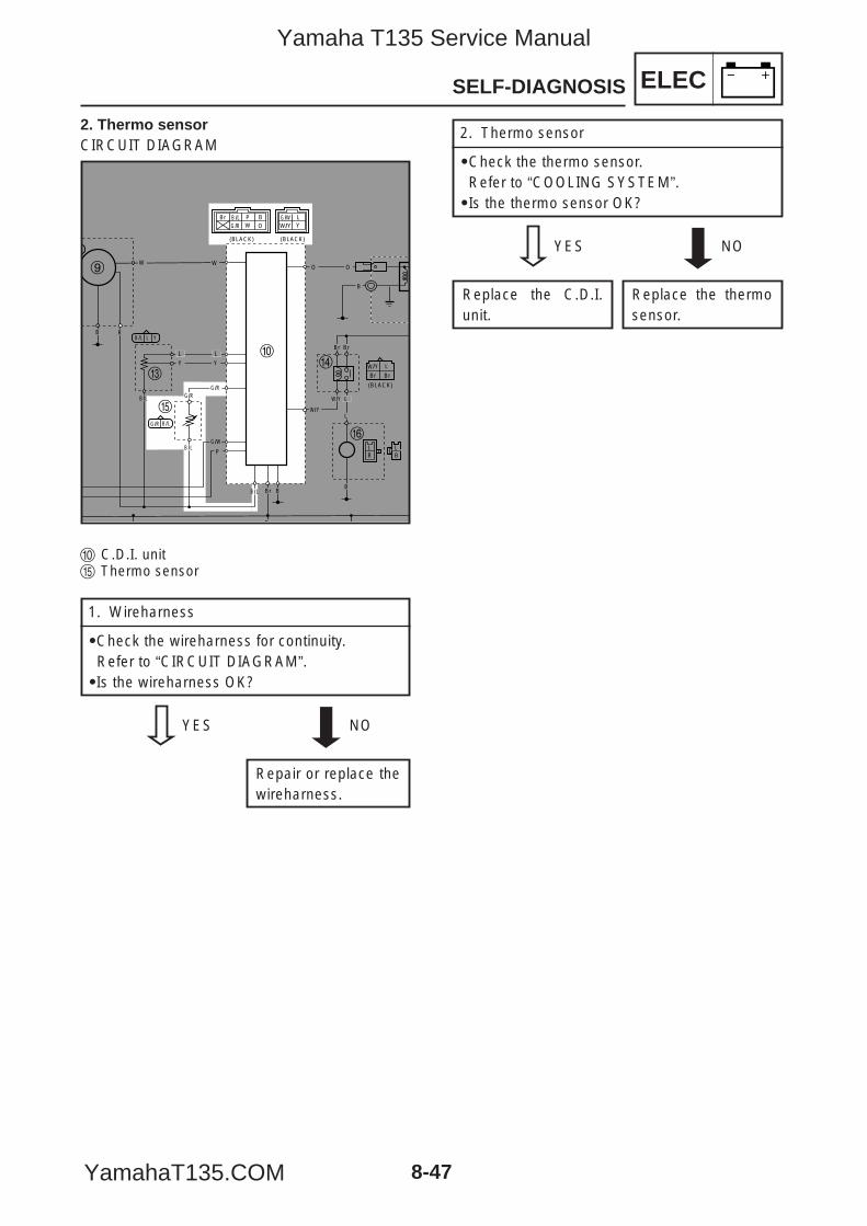
ELECSELF-DIAGNOSIS
8-47
2. Thermo sensorCIRCUIT DIAGRAM
0 C.D.I. unitt Thermo sensor
(BLACK)(BLACK)
(BLACK)
BrBr
L/YW
B
BB
O O
B /LG /R
G /R
G /W
B
W/Y Y
B /L
B /L
L Y
LPW
Br BO
W W
BL
BL
R
L
Y Y
L
L
P
L
Br
B /L
B /L
B /L Br
G /W
Y/W
Y/W
G /RG /R
BrBr
9
0
er
y
t
1. Wireharness
9Check the wireharness for continuity.Refer to “CIRCUIT DIAGRAM”.9Is the wireharness OK?
YES NO
Repair or replace thewireharness.
2. Thermo sensor
9Check the thermo sensor.Refer to “COOLING SYSTEM”.9Is the thermo sensor OK?
YES NO
Replace the thermosensor.
Replace the C.D.I.unit.
5YP-F8197-E0_8_1 05.6.27 19:28 Page 47
Yamaha T135 Service Manual
YamahaT135.COM

ELEC
5YP-F8197-E0_8_1 05.6.27 19:28 Page 48
Yamaha T135 Service Manual
YamahaT135.COM
TRBLSHTG
CHAPTER 9TROUBLESHOOTING
TROUBLESHOOTING ...........................................................................................9-1ELECTRICAL SYSTEM ....................................................................................9-1COMPRESSION SYSTEM ...............................................................................9-2INTAKE AND EXHAUST SYSTEM ...................................................................9-3
5YP-F8197-E0_9 05.5.4 13:14 Page 1
Yamaha T135 Service Manual
YamahaT135.COM
TRBLSHTG
5YP-F8197-E0_9 05.5.4 13:14 Page 2
Yamaha T135 Service Manual
YamahaT135.COM
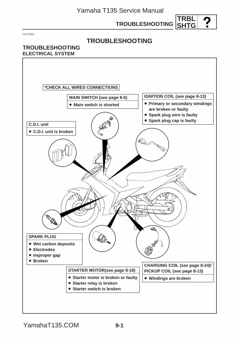
TRBLSHTGTROUBLESHOOTING
9-1
*CHECK ALL WIRES CONNECTIONS
MAIN SWITCH (see page 8-5)
8 Main switch is shorted
IGNITION COIL (see page 8-13)
8 Primary or secondary windingsare broken or faulty
8 Spark plug wire is faulty8 Spark plug cap is faulty
C.D.I. unit
8 C.D.I. unit is broken
CHARGING COIL (see page 8-24)/PICKUP COIL (see page 8-13)
8 Windings are broken
SPARK PLUG
8 Wet carbon deposits8 Electrodes8 Improper gap8 Broken
EASF0062
TROUBLESHOOTINGTROUBLESHOOTINGELECTRICAL SYSTEM
STARTER MOTOR(see page 8-18)
8 Starter motor is broken or faulty8 Starter relay is broken8 Starter switch is broken
5YP-F8197-E0_9 05.5.4 13:14 Page 3
Yamaha T135 Service Manual
YamahaT135.COM
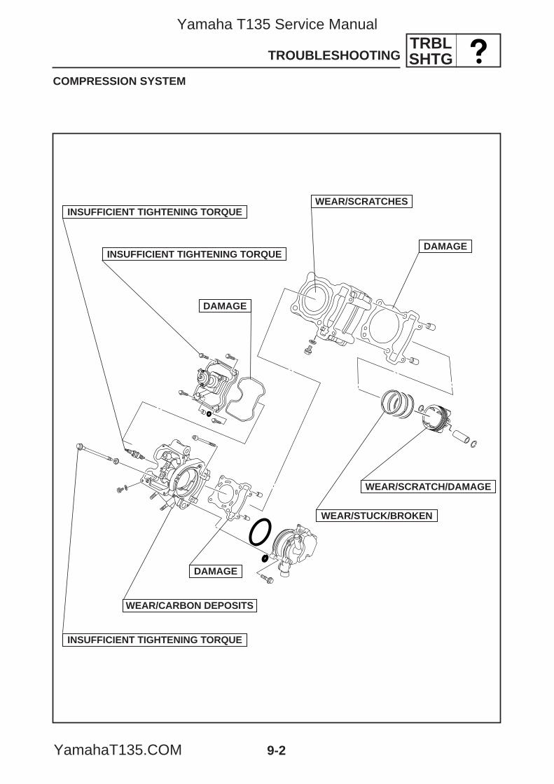
TRBLSHTGTROUBLESHOOTING
9-2
COMPRESSION SYSTEM
WEAR/SCRATCH/DAMAGE
WEAR/STUCK/BROKEN
DAMAGE
DAMAGE
WEAR/SCRATCHES
INSUFFICIENT TIGHTENING TORQUE
INSUFFICIENT TIGHTENING TORQUE
WEAR/CARBON DEPOSITS
DAMAGE
INSUFFICIENT TIGHTENING TORQUE
5YP-F8197-E0_9 05.5.4 13:14 Page 4
Yamaha T135 Service Manual
YamahaT135.COM
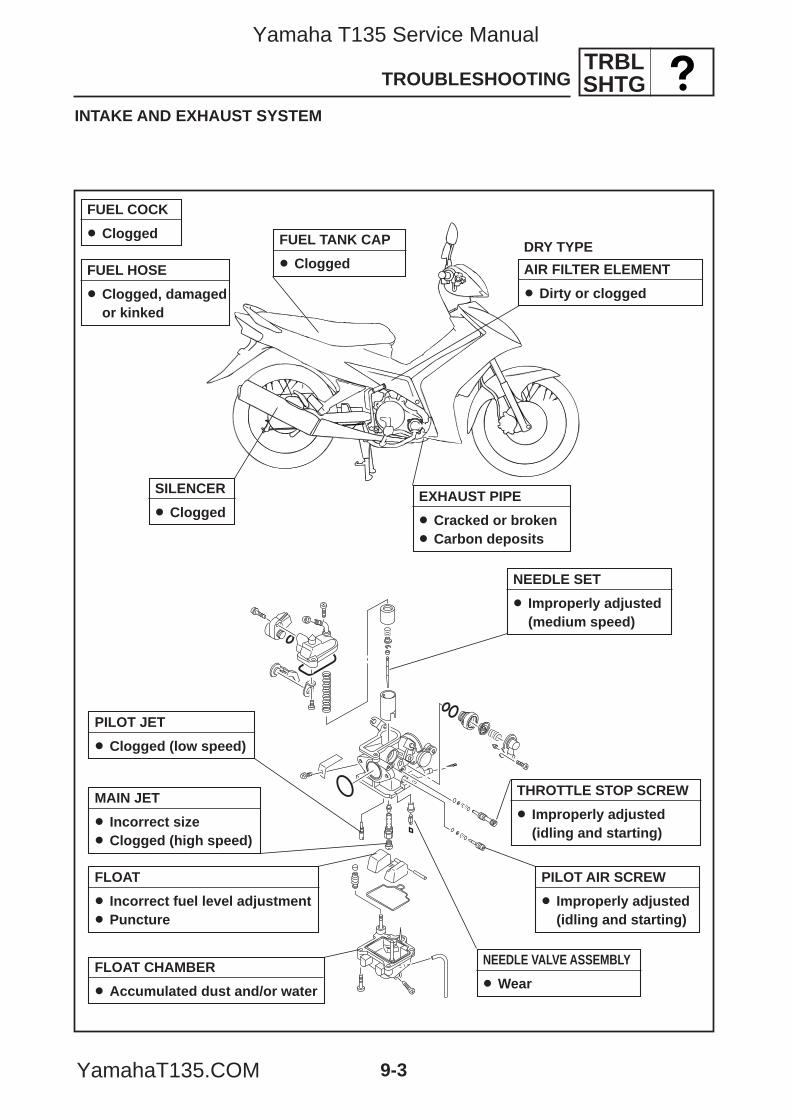
TRBLSHTGTROUBLESHOOTING
9-3
INTAKE AND EXHAUST SYSTEM
FUEL COCK
8 Clogged
FUEL HOSE
8 Clogged, damagedor kinked
FUEL TANK CAP
8 Clogged AIR FILTER ELEMENT
8 Dirty or clogged
DRY TYPE
THROTTLE STOP SCREW
8 Improperly adjusted(idling and starting)
NEEDLE VALVE ASSEMBLY
8 Wear
PILOT JET
8 Clogged (low speed)
FLOAT CHAMBER
8 Accumulated dust and/or water
FLOAT
8 Incorrect fuel level adjustment8 Puncture
MAIN JET
8 Incorrect size8 Clogged (high speed)
PILOT AIR SCREW
8 Improperly adjusted(idling and starting)
EXHAUST PIPE
8 Cracked or broken8 Carbon deposits
SILENCER
8 Clogged
NEEDLE SET
8 Improperly adjusted(medium speed)
5YP-F8197-E0_9 05.5.4 13:14 Page 5
Yamaha T135 Service Manual
YamahaT135.COM

TRBLSHTG
5YP-F8197-E0_9 05.5.4 13:14 Page 6
Yamaha T135 Service Manual
YamahaT135.COM

Yamaha T135 Service Manual
YamahaT135.COM
YAMAHA MOTOR CO., LTD.2500 SHINGAI IWATA SHIZUOKA JAPAN
5YP-F8197-E0_ cover 05.5.9 17:35 Page 2
Yamaha T135 Service Manual
YamahaT135.COM
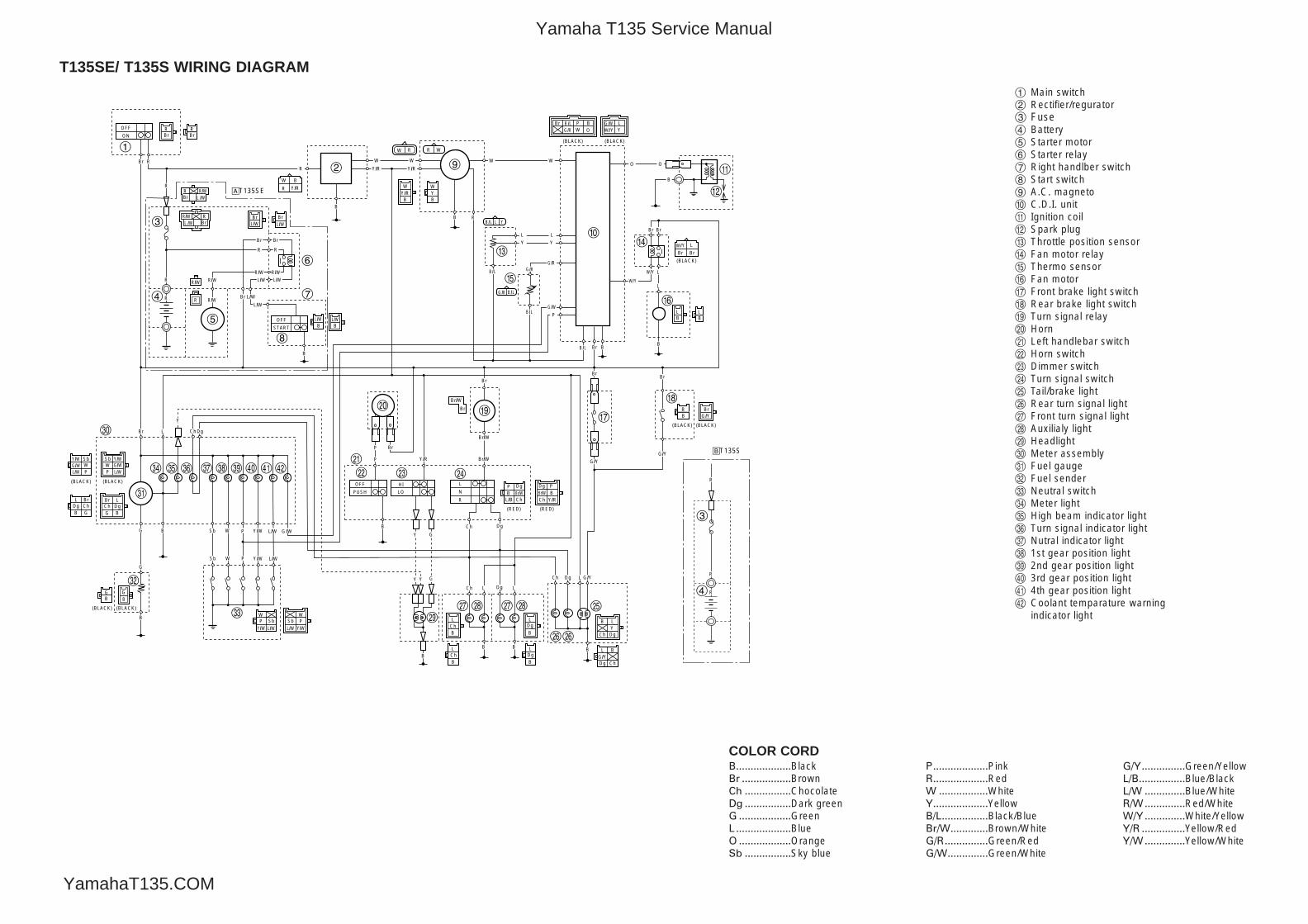
1 Main switch2 Rectifier/regurator3 Fuse4 Battery5 Starter motor6 Starter relay7 Right handlber switch8 Start switch9 A.C. magneto0 C.D.I. unitq Ignition coilw Spark pluge Throttle position sensorr Fan motor relayt Thermo sensory Fan motoru Front brake light switchi Rear brake light switcho Turn signal relayp Horna Left handlebar switchs Horn switchd Dimmer switchf Turn signal switchg Tail/brake lighth Rear turn signal lightj Front turn signal lightk Auxilialy lightl Headlight; Meter assemblyz Fuel gaugex Fuel senderc Neutral switchv Meter lightb High beam indicator lightn Turn signal indicator lightm Nutral indicator light, 1st gear position light. 2nd gear position light/ 3rd gear position light! 4th gear position light@ Coolant temparature warning
indicator light
T135SE/ T135S WIRING DIAGRAM
B...................BlackBr .................BrownCh ................ChocolateDg ................Dark greenG ..................GreenL ...................BlueO ..................OrangeSb ................Sky blue
P...................PinkR...................RedW .................WhiteY...................YellowB/L................Black/BlueBr/W.............Brown/WhiteG/R...............Green/RedG/W..............Green/White
G/Y...............Green/YellowL/B................Blue/BlackL/W ..............Blue/WhiteR/W..............Red/WhiteW/Y..............White/YellowY/R ...............Yellow/RedY/W..............Yellow/White
COLOR CORD
RBr
W W
OFF
ON
Br R
R
OFF
START
B
L/W
L/W
B
B Sb W P Y/W L/W
Sb W P Y/W L/W
G
G
L DgChBr
BG
R
Br
Br
R
Br
L/WL/W
R/WR/W
R/W
Y
Sb Y/W
P L/WW
L/WG/W G/W
SbW
Y/W
P
Br LDg
G BChDg
B
BrCh
L
G
(BLACK)
(BLACK) (BLACK)
(BLACK)(BLACK)
(BLACK)
(BLACK)(BLACK)
(BLACK)
Y/WL/WSb
Y/W L/W
W WSbP P
R
R
B
W B
Br
Br
Br
L/YW
B
BB
R
R
O O
WY/RB
YB
W
BrL/W
BrL/W
BBL/W L/W
B /LG /R
G /R
G /W
B
Br
G/Y
G/Y
G/Y
Br
Br/W
Br/W
Br/W
Br
Y/R
L
N
R
Ch Dg L G/Y
P
B
Y G
GYY
P
HI
LO
OFF
PUSH Br/WCh
BDg
L/B
W/Y Y
PB
Y/RBr/W
P
Ch
Dg
(RED)(RED)
Br
B B
B
Ch Dg
Ch Dg
B
L
L
B
B
L
L
B LY
Ch Dg
G/YDg
BL
Ch
RW WR
B /L
B /L
L Y
GB
LPW
Br BO
Y/RY/R
Y/R
W W
R
R/W
BrR
BL
BL
BB
R/W
R
L
Y Y
L
L
P
L
Br
B /L
B /L
B /L Br
G /W
Y/W
Y/W
G /RG /R
G /W
B
B
Ch Dg
Ch DgL L
BrBr
L /WRBr
R/W
L /WR
BrR/W
1
2
3
4
5
6
7
8
9
0
q
w
er
y
t
u
ip o
a
s d f
gj j
hh
k kl
;
z
x
v
c
b n m , . / ! @
R
R
3
4
åT135SE
∫T135S
R
5YP-F8197-E0_A3yoko 05.5.9 18:02 Page 1
Yamaha T135 Service Manual
YamahaT135.COM