Embed Size (px)
Citation preview
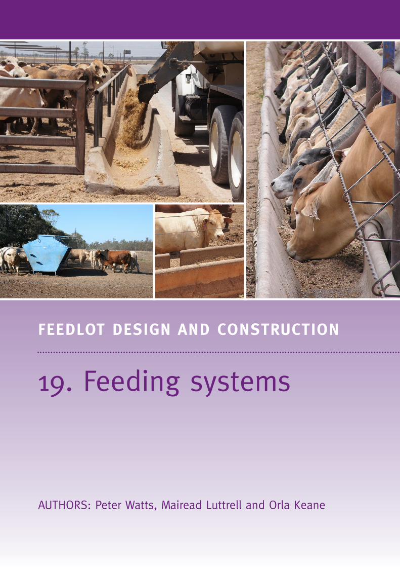
19. Feeding systems
AUTHORS: Peter Watts, Mairead Luttrell and Orla Keane
FEEDLOT DESIGN AND CONSTRUCTION
2
FEEDLOT DESIGN AND CONSTRUCTION
19. Feeding systems
IntroductionThe feeding system must be well designed to achieve good cattle performance, efficient feedlot operation and for maintaining high environmental standards.
Design objectivesFeeding systems should• provide livestock with free and continual access to feed• maintain fresh and palatable feed• minimise waste, spilled feed and spoilage• prevent all classes of cattle from fouling the feed and escaping
from the pens• allow easy delivery of feed• allow for easy cleaning and removal of spoiled feed after rainfall• not inhibit pen cleaning• minimise environmental impacts (odour, flies, dust)• minimise ongoing maintenance costs• provide a safe working environment for pen riders and other
feedlot personnel.
Mandatory requirementsCompliance with• Australian Animal Standards and Guidelines for Cattle
(DAFF, 2013).• National Guidelines for Beef Cattle Feedlots in Australia
(MLA, 2012a).• National Beef Cattle Feedlot Environmental Code of Practice
(MLA, 2012b).• NFAS standards (AUS-MEAT, 2011).
Design choicesThe feeding system can use either self-feeder bins or open feed bunks.
Self-feeders
Self-feeders are best suited to small and/or opportunity feedlots which do not prepare their own rations or where rations are milled and mixed off site.
Advantages of self-feeders include that they• have their own storage bins and so need filling only once or
twice a week• are readily transportable, can be installed quickly, can be used
as a temporary feed-out system • can be used elsewhere on the farm or in a small paddock or
yard to form a temporary feedlot for drought feeding• can be moved around within pens.
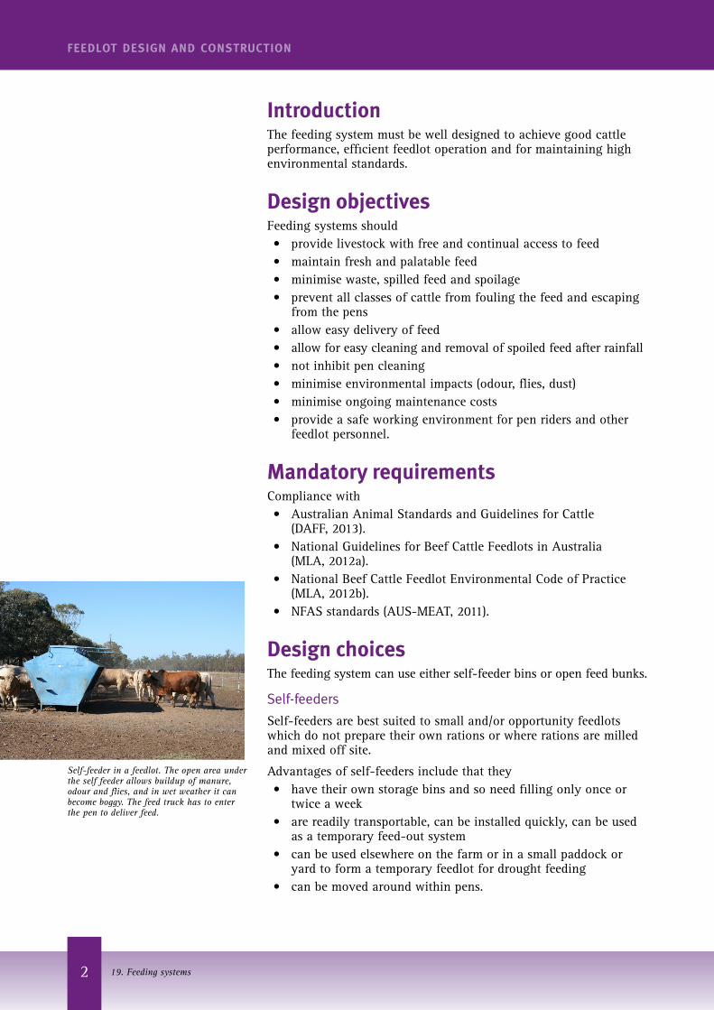
Self-feeder in a feedlot. The open area under the self feeder allows buildup of manure, odour and flies, and in wet weather it can become boggy. The feed truck has to enter the pen to deliver feed.
3
FEEDLOT DESIGN AND CONSTRUCTION
19. Feeding systems
Problems with self-feeders in feedlots include• Rations that are moist, contain large amounts of roughage
(particularly coarse roughage) or contain molasses or oils may bridge and restrict feed supply.
• If a self-feeder bridges or is allowed to empty completely, cattle are likely to gorge on feed when it is delivered. This can result in acidosis and deaths.
• Hay racks often need to be used with self-feeders, particularly during the introductory feeding phase.
• Moist feeds tend to ‘go off’ or spoil when stored in self-feeders for several days.
• Manure and spilt feed accumulate under the feeder generating odour and fly breeding sites, unless the feeder is designed well and the area cleaned frequently.
• Self-feeders must be located so that they can be filled during all weather conditions, preferably from outside the pens. This is possible only where the feed trough is on one side and they can be placed parallel to and up against the top fence.
• Self-feeders with feed troughs on both sides must be placed at right angles to the top fence and are therefore more difficult to fill from outside the pens.
• They should be located at the top side of pens so that they have minimal impact on pen drainage.
The size and number of self-feeders depends on the number and estimated feed intake of cattle being fed, the frequency of filling and the type of ration. Self-feeders typically have capacities of 3.5 tonne, 5.5 tonne and 7.5 tonne. Based on an average dry matter intake (DMI) of 12 kg DM/head/day and a moisture content of 12%, the as-fed intake would be about 13.4 kg/head/day. Table 1 calculates the number of self-feeders needed for pens of different capacity.
Table 1. Number of self feeders/pen for weekly feeding
SCU/pen
100 150 200
Self feeder capacity (kg) No. of self feeders
3500 3 5 6
5500 2 3 4
7500 2 2 3
Feed bunks and aprons
Most commercial feedlots use open feed bunks (troughs). They generally process their own feed and can feed-out more than once a day. All types of rations, including those moist or containing large amounts of coarsely chopped fibre, can be fed in troughs.
Location
Feed bunks should always be located along the fence line, never within the pen, so that they can be filled during all weather conditions. They should be located along the higher end of the pen with drainage away from the bunk on both the feed road and pen sides. This minimises boggy conditions on the pen side of the bunk and keeps the feed road firm and accessible.
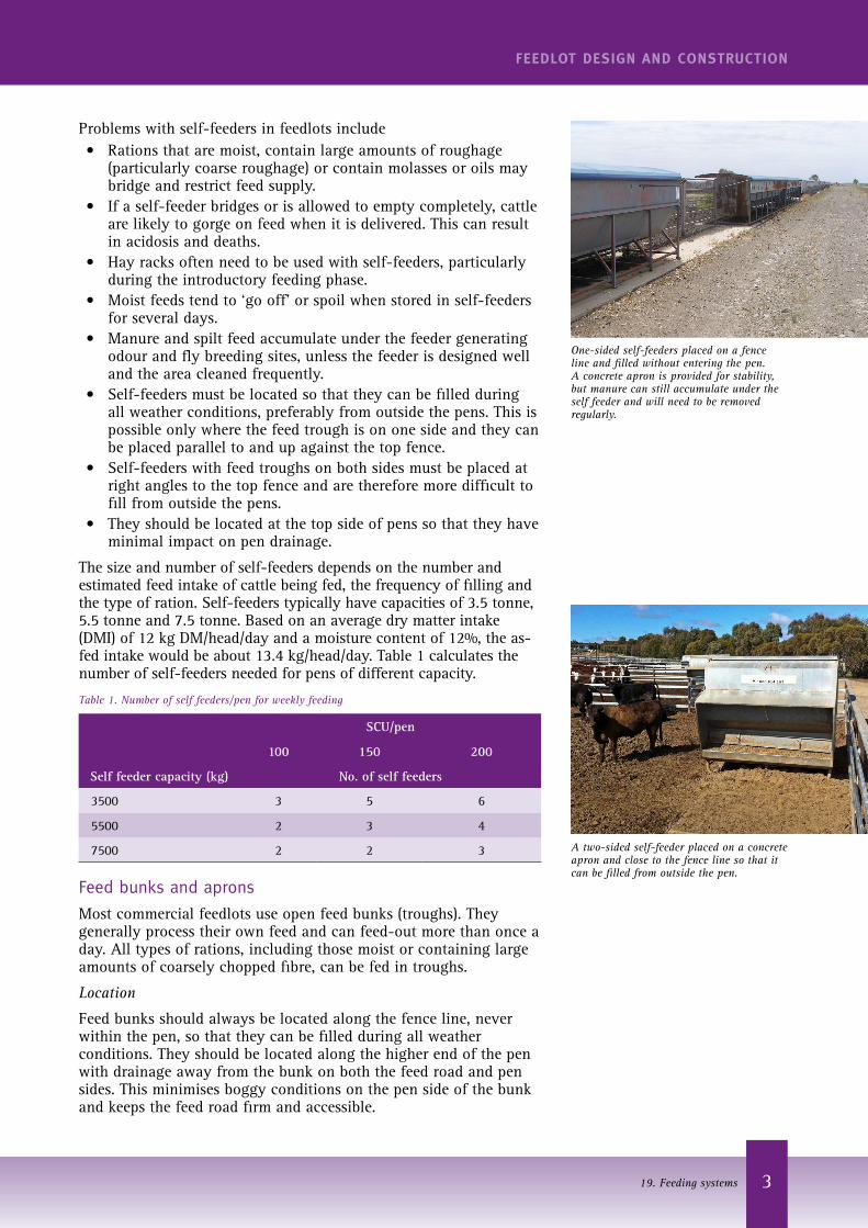
One-sided self-feeders placed on a fence line and filled without entering the pen. A concrete apron is provided for stability, but manure can still accumulate under the self feeder and will need to be removed regularly.
A two-sided self-feeder placed on a concrete apron and close to the fence line so that it can be filled from outside the pen.
4
FEEDLOT DESIGN AND CONSTRUCTION
19. Feeding systems
Bunk length
The length of a bunk depends on the number of cattle in the pen and the dimensions of the pen. Bunks usually run the entire length of the pen although some feedlots provide access gates in the top end of their pens. The type of feed ration (bulkiness), size of the cattle and desired feeding frequency must also be considered.
Bunk length per head
Most lot feeders would require 250 mm to 300 mm per head of bunk space.
The temptation to design for 200 mm of bunk space per head in order to minimise building costs may be false economy if 50 or 100 mm extra space would enhance cattle performance.
A shorter bunk space may restrict the opportunity of shy feeders to feed, particularly during the introductory phase. In these cases, some cattle will take longer to adapt to the high energy ration, there may be more cases of acidosis, less uniform finishing of cattle within pens and lower average daily weight gain of cattle within the pen.
Fence posts
Fence posts along the feed bunk may be cast into the bunk itself (for bunks that are cast on site), located against the vertical wall of the bunk on the pen side or on the inside of the feed bunk (for either pre-cast or cast on site). The posts can be built into a feed bunk wall of uniform thickness or with a locally thickened wall around the post.
A feed bunk wall of uniform thickness will make it easier to remove accumulated waste but the wall must be thicker to prevent it from cracking or from damage during pen cleaning; this will add substantially to the capital cost.
Local thickening of concrete around the posts, or having the posts on the outside of the feed bunk, will make it difficult to clean around them to remove manure that has built up against the bunk wall and to clean along the feed trough apron. Posts that are cast into the concrete wall need to be treated with epoxy or equivalent to prevent corrosion at the steel/concrete joint and subsequent failure.
All steel posts need to be capped top and bottom to prevent water entry and subsequent rusting. Top rails are highly recommended along feed trough posts as these help to strengthen the whole feed-bunk fence system which is continually being pushed by feeding cattle. An expansion joint every 25 m in long cattle rails will prevent buckling.
Restraint devices
Cattle must be prevented from entering the feed bunk and possibly escaping. This has been achieved using a system of cables strung out over the feed bunk, but this can make it difficult to maintain and clean the trough. In most modern feedlots, cattle are constrained by the design of the feed bunk back wall and a single cattle rail.
An adjustable height cable below the cattle rail or an adjustable rail will restrain a range of cattle sizes in a pen.
The judicious use of an electric wire adjacent the cattle rail or top cable can help teach cattle not to press against the restraint system.
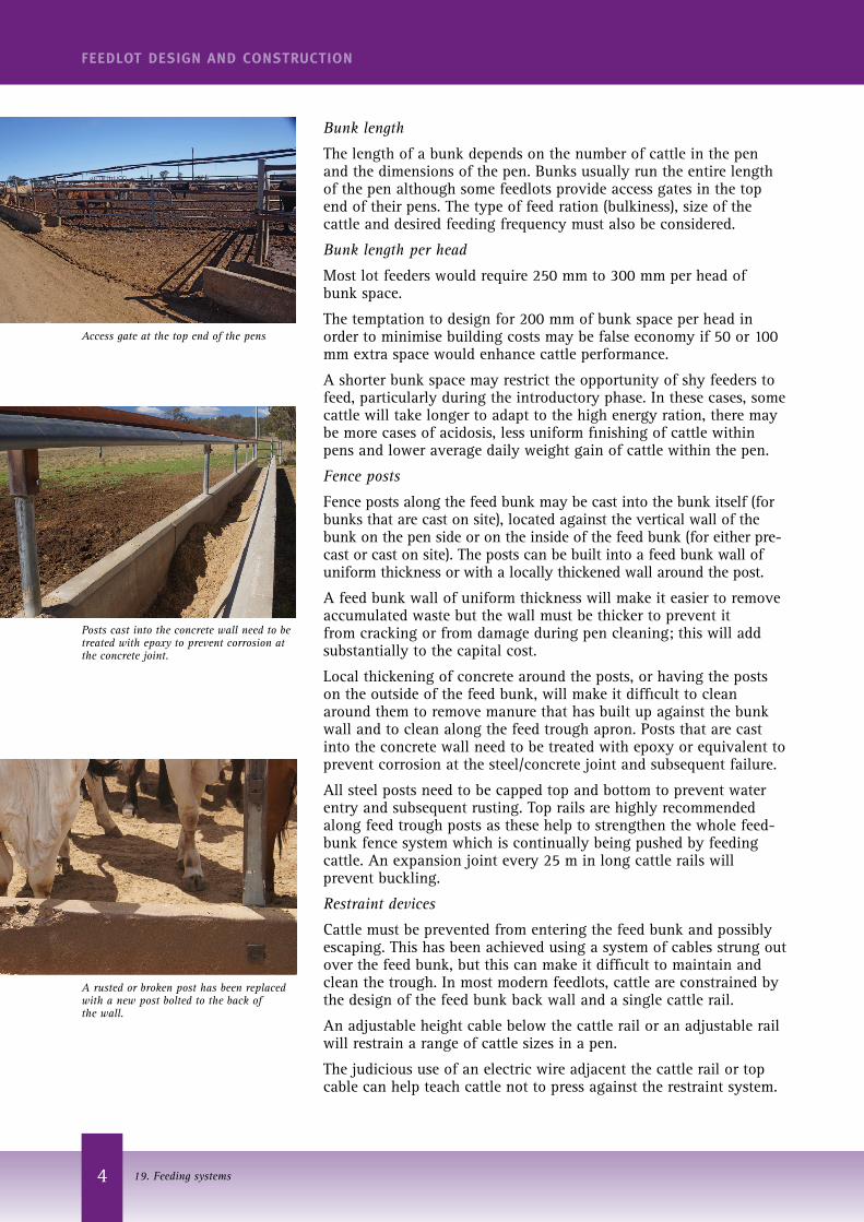
Access gate at the top end of the pens
Posts cast into the concrete wall need to be treated with epoxy to prevent corrosion at the concrete joint.
A rusted or broken post has been replaced with a new post bolted to the back of the wall.
5
FEEDLOT DESIGN AND CONSTRUCTION
19. Feeding systems
Cross-sectional dimensions
The cross-sectional area of the trough determines the amount of feed that can fit into the trough per unit length. If the cross-sectional area is too small frequent filling will be necessary, particularly if silage or other bulky ingredients are fed. If the feed bunk is too wide, feed pushed to the back of the bunk is less accessible and cattle are tempted to step into the trough to try to reach it.
Feed bunks should have vertical external faces on either side for ease of removing built-up manure and spilt grain. Outwardly sloping sides make wastes trapped around them difficult to remove, but may reduce damage by the feed truck.
The inside of the feed bunks should be smooth with rounded corners. Square inner corners will trap inaccessible feed allowing it to become mouldy or stale, and are also difficult to clean.
Feed bunks should allow rainwater to drain, preferably by having drain holes or slots at intervals along the length of the trough. These drainage points need to be large enough that they do not get blocked. Water can also drain if a shorter feed bunk is left open at the end. Adequate slope (>1%) longitudinally along the feed road and bunk enhances drainage after storms.
Feed bunks must be designed for easy filling. They should be readily fillable from the feed road side without opening and closing gates. Feed alleys should be straight and not curved to minimise spillages and damage by the feed truck; the approach should have a straight section so the truck is moving parallel to the trough when unloading.
Over the years, a wide range of different feed bunk dimensions have been used.
Table 2 gives the dimensions of several different types. Important dimensions are
H1 – the height of the back wall above the feed apron. This should be 500 mm high to prevent cattle stepping into the feed bunk.
H2 – the height of the front wall above the feed road. This needs to be higher than the back wall but not so high that it interferes with feed delivery. Experience indicates that this should be 700-750 mm high.
H3 – the height of the cattle restraint rail above the apron. In conjunction with H1, these dimensions allow cattle free access to feed without rubbing or awkward bending but prevent cattle from stepping out of the pen into the trough. H3 should be lower for smaller cattle and therefore a restraint system where H3 can be varied is desirable. Typically, H3 should be about 1000–1150 mm above the feed apron.
W1 – the width of the feed storage area of the bunk. In conjunction with other dimensions, it determines the volume of feed that can be held. If W1 is too large, cattle cannot reach feed without straining.
W2 and W3 – the thicknesses of the front and back walls. Greater thickness provides more bunk strength but adds to the volume and cost of concrete required.
A1 – the cross-sectional area of feed per metre length of bunk. The Type D bunk is an old design that provided only 0.15 m2 of feed, and has been found to be inadequate. Newer bunks provide over 0.2 m2 of feed per unit length, which is 30% more than Type D.
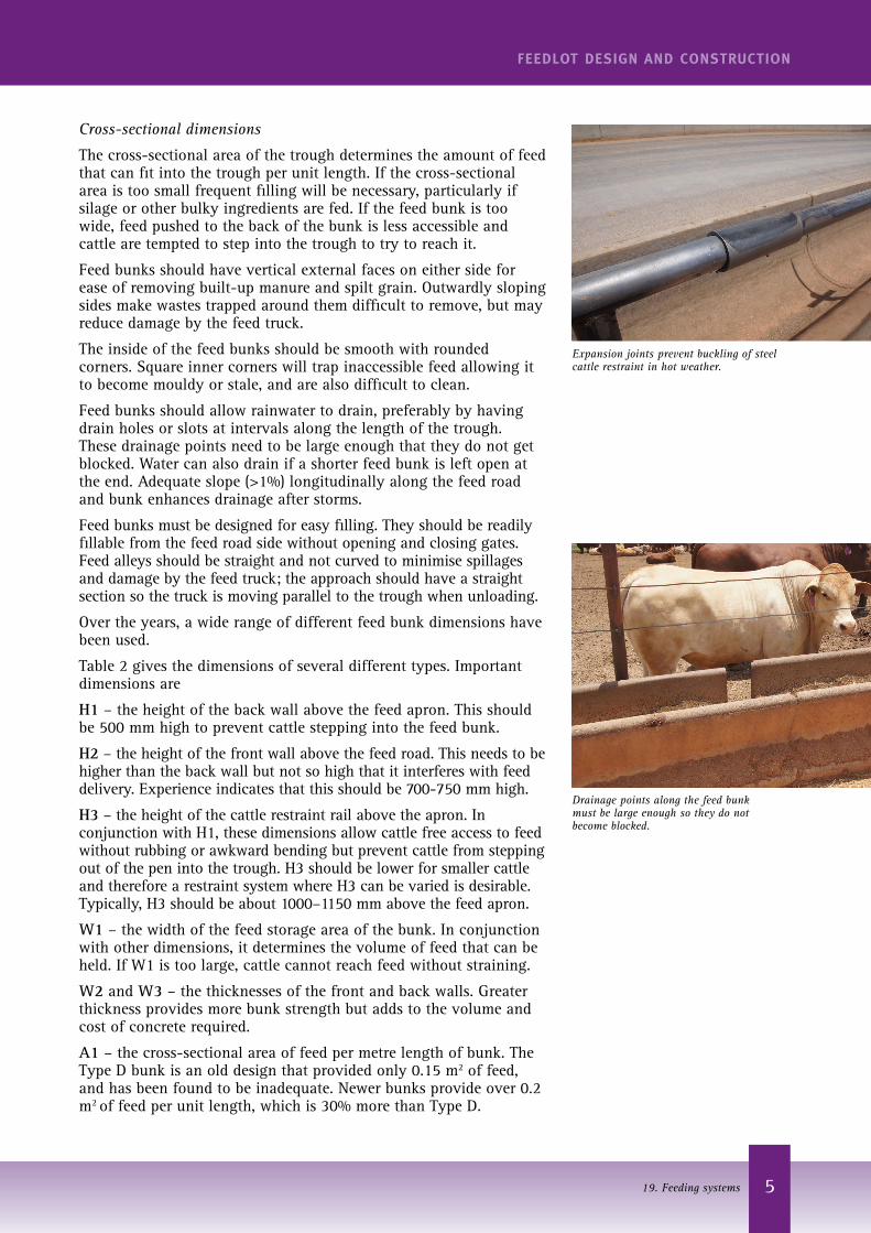
Drainage points along the feed bunk must be large enough so they do not become blocked.
Expansion joints prevent buckling of steel cattle restraint in hot weather.
6
FEEDLOT DESIGN AND CONSTRUCTION
19. Feeding systems
A2 – the cross-sectional area of concrete for the bunk. This dimension has a large bearing on capital cost. The old Type D trough has less than half of the concrete per unit length than the new bunk, but this is at the expense of feed volume and cattle constraint.
The following sections show most of these sample feed bunks.
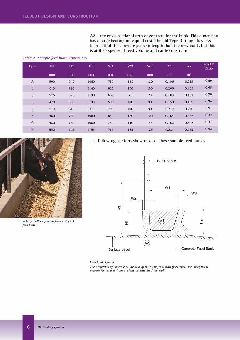
Table 2. Sample feed bunk dimensions
Type H1 H2 H3 W1 W2 W3 A1 A2 A1/A2 Ratio
mm mm mm mm mm mm m2 m2
A 500 545 1080 715 135 120 0.196 0.219 0.89
B 610 790 1140 825 150 100 0.266 0.409 0.65
C 575 625 1190 662 75 70 0.183 0.187 0.98
D 429 550 1100 590 100 90 0.150 0.159 0.94
E 519 619 1110 790 100 90 0.219 0.240 0.91
F 480 750 1080 840 160 100 0.164 0.386 0.42
G 480 760 1000 780 140 70 0.162 0.347 0.47
H 550 725 1155 715 125 125 0.221 0.239 0.92
Feed bunk Type AThe projection of concrete at the base of the bunk front wall (feed road) was designed to prevent feed trucks from pushing against the front wall.
A large bullock feeding from a Type A feed bunk
7
FEEDLOT DESIGN AND CONSTRUCTION
19. Feeding systems
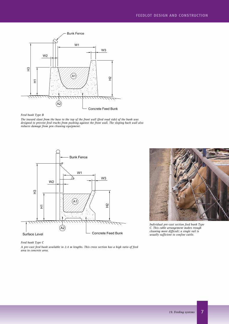
Feed bunk Type CA pre-cast feed bunk available in 2.4 m lengths. This cross section has a high ratio of feed area to concrete area.
Individual pre-cast section feed bunk Type C. This cable arrangement makes trough cleaning more difficult; a single rail is usually sufficient to confine cattle.
Feed bunk Type BThe inward slant from the base to the top of the front wall (feed road side) of the bunk was designed to prevent feed trucks from pushing against the front wall. The sloping back wall also reduces damage from pen cleaning equipment.
8
FEEDLOT DESIGN AND CONSTRUCTION
19. Feeding systems
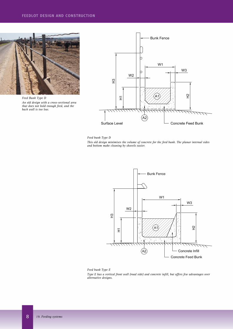
Feed bunk Type DThis old design minimises the volume of concrete for the feed bunk. The planar internal sides and bottom make cleaning by shovels easier.
Feed Bunk Type DAn old design with a cross-sectional area that does not hold enough feed, and the back wall is too low.
Feed bunk Type EType E has a vertical front wall (road side) and concrete infill, but offers few advantages over alternative designs.
9
FEEDLOT DESIGN AND CONSTRUCTION
19. Feeding systems
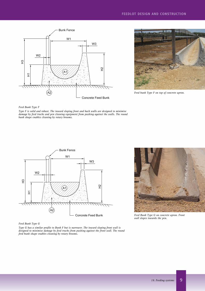
Feed Bunk Type FType F is solid and robust. The inward sloping front and back walls are designed to minimise damage by feed trucks and pen cleaning equipment from pushing against the walls. The round bunk shape enables cleaning by rotary brooms.
Feed bunk Type F on top of concrete apron.
Feed Bunk Type GType G has a similar profile to Bunk F but is narrower. The inward sloping front wall is designed to minimise damage by feed trucks from pushing against the front wall. The round feed bunk shape enables cleaning by rotary brooms.
Feed Bunk Type G on concrete apron. Front wall slopes towards the pen.
10
FEEDLOT DESIGN AND CONSTRUCTION
19. Feeding systems
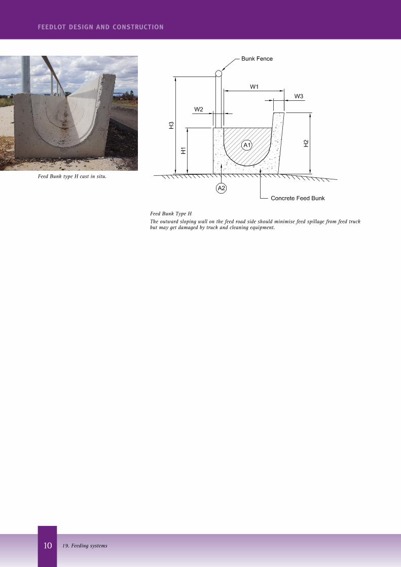
Feed Bunk Type HThe outward sloping wall on the feed road side should minimise feed spillage from feed truck but may get damaged by truck and cleaning equipment.
Feed Bunk type H cast in situ.
11
FEEDLOT DESIGN AND CONSTRUCTION
19. Feeding systems
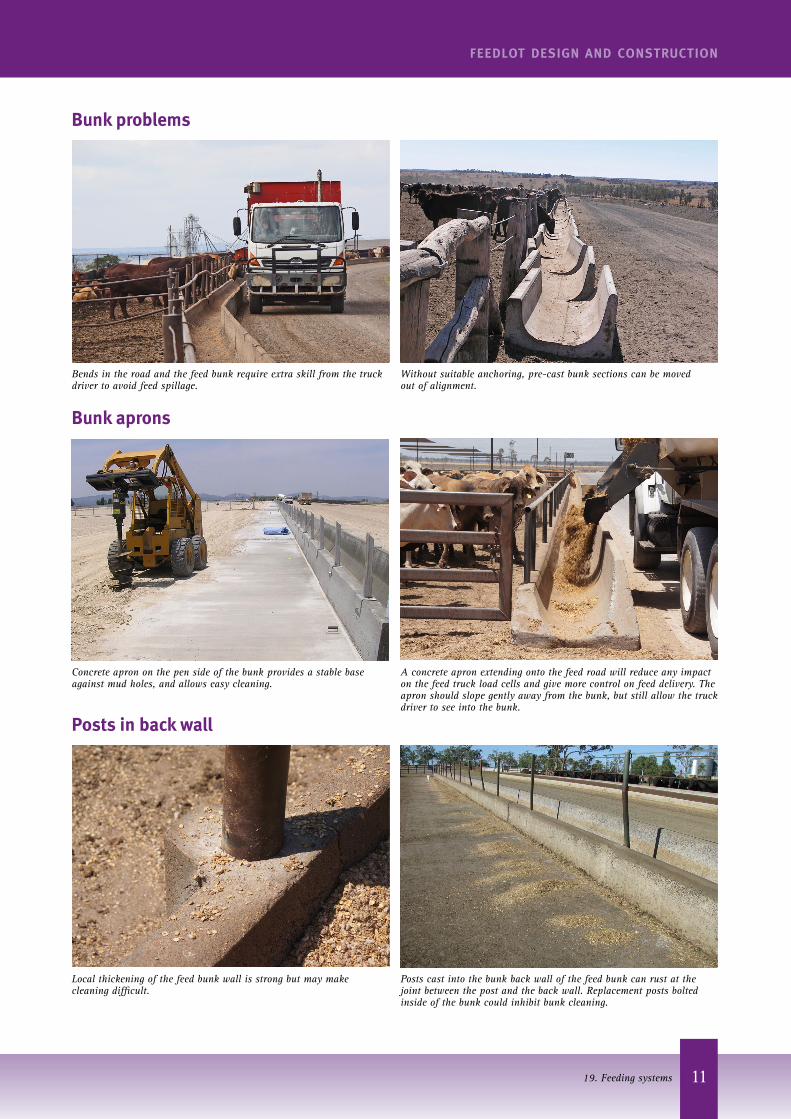
Bends in the road and the feed bunk require extra skill from the truck driver to avoid feed spillage.
Without suitable anchoring, pre-cast bunk sections can be moved out of alignment.
Bunk problems
Concrete apron on the pen side of the bunk provides a stable base against mud holes, and allows easy cleaning.
A concrete apron extending onto the feed road will reduce any impact on the feed truck load cells and give more control on feed delivery. The apron should slope gently away from the bunk, but still allow the truck driver to see into the bunk.
Bunk aprons
Local thickening of the feed bunk wall is strong but may make cleaning difficult.
Posts cast into the bunk back wall of the feed bunk can rust at the joint between the post and the back wall. Replacement posts bolted inside of the bunk could inhibit bunk cleaning.
Posts in back wall
12
FEEDLOT DESIGN AND CONSTRUCTION
19. Feeding systems
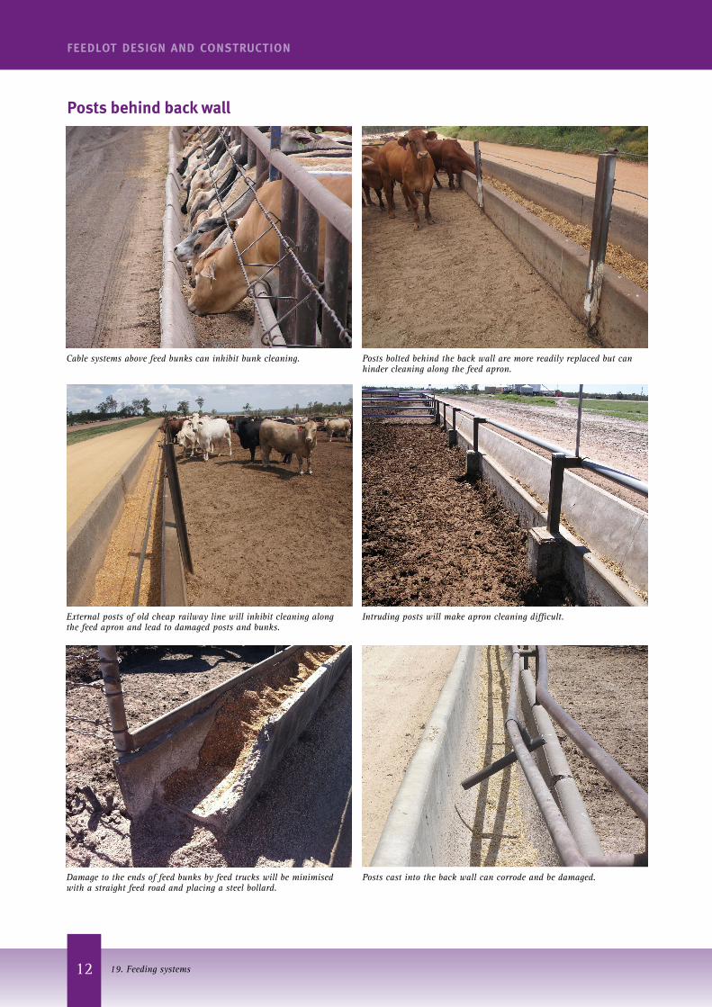
Cable systems above feed bunks can inhibit bunk cleaning.
External posts of old cheap railway line will inhibit cleaning along the feed apron and lead to damaged posts and bunks.
Damage to the ends of feed bunks by feed trucks will be minimised with a straight feed road and placing a steel bollard.
Posts behind back wall
Posts bolted behind the back wall are more readily replaced but can hinder cleaning along the feed apron.
Intruding posts will make apron cleaning difficult.
Posts cast into the back wall can corrode and be damaged.
13
FEEDLOT DESIGN AND CONSTRUCTION
19. Feeding systems
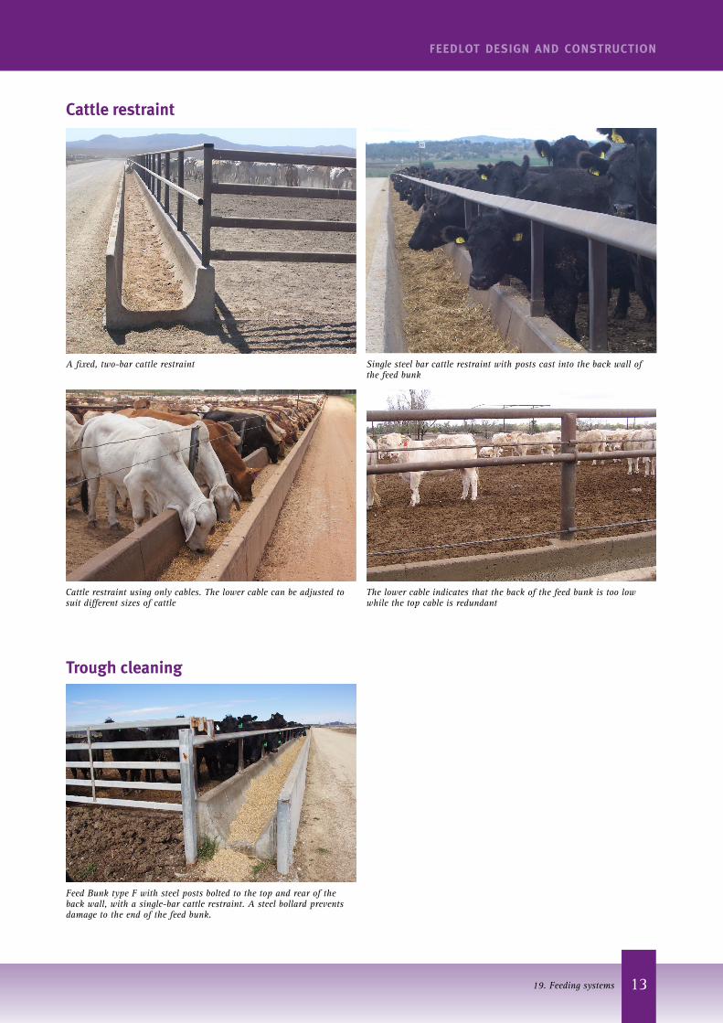
A fixed, two-bar cattle restraint
Cattle restraint using only cables. The lower cable can be adjusted to suit different sizes of cattle
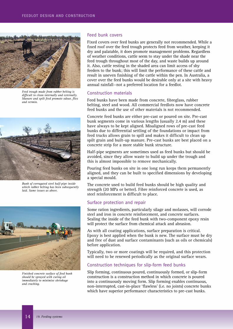
Feed Bunk type F with steel posts bolted to the top and rear of the back wall, with a single-bar cattle restraint. A steel bollard prevents damage to the end of the feed bunk.
The lower cable indicates that the back of the feed bunk is too low while the top cable is redundant
Single steel bar cattle restraint with posts cast into the back wall of the feed bunk
Trough cleaning
Cattle restraint
14
FEEDLOT DESIGN AND CONSTRUCTION
19. Feeding systems
Feed bunk covers
Fixed covers over feed bunks are generally not recommended. While a fixed roof over the feed trough protects feed from weather, keeping it dry and palatable, it does promote management problems. Regardless of weather conditions, cattle seem to stay under the shade near the feed trough throughout most of the day, and waste builds up around it. Also, cattle resting in the shaded area can limit access of shy feeders to the bunk; this will limit the performance of these cattle and result in uneven finishing of the cattle within the pen. In Australia, a cover over the feed bunks would be desirable only at a site with heavy annual rainfall—not a preferred location for a feedlot.
Construction materials
Feed bunks have been made from concrete, fibreglass, rubber belting, steel and wood. All commercial feedlots now have concrete feed bunks and the use of other materials is not recommended.
Concrete feed bunks are either pre-cast or poured on site. Pre-cast bunk segments come in various lengths (usually 2.4 m) and these have always to be kept aligned. Misaligned rows of pre-cast feed bunks due to differential settling of the foundations or impact from feed trucks allows grain to spill and makes it difficult to clean up spilt grain and built-up manure. Pre-cast bunks are best placed on a concrete strip for a more stable bunk structure.
Half-pipe segments are sometimes used as feed bunks but should be avoided, since they allow waste to build up under the trough and this is almost impossible to remove mechanically.
Pouring feed bunks on site in one long run keeps them permanently aligned, and they can be built to specified dimensions by developing a special mould.
The concrete used to build feed bunks should be high quality and strength (20 MPa or better). Fibre reinforced concrete is used, as steel reinforcement is difficult to place.
Surface protection and repair
Some ration ingredients, particularly silage and molasses, will corrode steel and iron in concrete reinforcement, and concrete surfaces. Sealing the inside of the feed bunk with two-component epoxy resin will protect the surface from chemical attack and abrasion.
As with all coating applications, surface preparation is critical. Epoxy is best applied when the bunk is new. The surface must be dry and free of dust and surface contaminants (such as oils or chemicals) before application.
Typically, two or more coatings will be required, and this protection will need to be renewed periodically as the original surface wears.
Construction techniques for slip-form feed bunks
Slip forming, continuous poured, continuously formed, or slip-form construction is a construction method in which concrete is poured into a continuously moving form. Slip forming enables continuous, non-interrupted, cast-in-place ‘flawless’ (i.e. no joints) concrete bunks which have superior performance characteristics to pre-cast bunks.
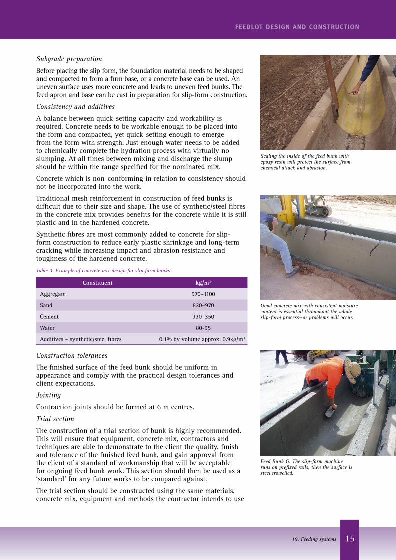
Finished concrete surface of feed bunk should be sprayed with curing oil immediately to minimise shrinkage and cracking.
Feed trough made from rubber belting is difficult to clean internally and externally.Manure and spilt feed promote odour, flies and vermin.
Bunk of corrugated steel half-pipe inside which rubber belting has been subsequently laid. Same issues as above.
15
FEEDLOT DESIGN AND CONSTRUCTION
19. Feeding systems
Subgrade preparation
Before placing the slip form, the foundation material needs to be shaped and compacted to form a firm base, or a concrete base can be used. An uneven surface uses more concrete and leads to uneven feed bunks. The feed apron and base can be cast in preparation for slip-form construction.
Consistency and additives
A balance between quick-setting capacity and workability is required. Concrete needs to be workable enough to be placed into the form and compacted, yet quick-setting enough to emerge from the form with strength. Just enough water needs to be added to chemically complete the hydration process with virtually no slumping. At all times between mixing and discharge the slump should be within the range specified for the nominated mix.
Concrete which is non-conforming in relation to consistency should not be incorporated into the work.
Traditional mesh reinforcement in construction of feed bunks is difficult due to their size and shape. The use of synthetic/steel fibres in the concrete mix provides benefits for the concrete while it is still plastic and in the hardened concrete.
Synthetic fibres are most commonly added to concrete for slip-form construction to reduce early plastic shrinkage and long-term cracking while increasing impact and abrasion resistance and toughness of the hardened concrete.
Table 3. Example of concrete mix design for slip form bunks
Constituent kg/m3
Aggregate 970–1100
Sand 820–970
Cement 330–350
Water 80-95
Additives – synthetic/steel fibres 0.1% by volume approx. 0.9kg/m3
Construction tolerances
The finished surface of the feed bunk should be uniform in appearance and comply with the practical design tolerances and client expectations.
Jointing
Contraction joints should be formed at 6 m centres.
Trial section
The construction of a trial section of bunk is highly recommended. This will ensure that equipment, concrete mix, contractors and techniques are able to demonstrate to the client the quality, finish and tolerance of the finished feed bunk, and gain approval from the client of a standard of workmanship that will be acceptable for ongoing feed bunk work. This section should then be used as a ‘standard’ for any future works to be compared against.
The trial section should be constructed using the same materials, concrete mix, equipment and methods the contractor intends to use
Feed Bunk G. The slip-form machine runs on prefixed rails, then the surface is steel trowelled.
Good concrete mix with consistent moisture content is essential throughout the whole slip-form process—or problems will occur.
Sealing the inside of the feed bunk with epoxy resin will protect the surface from chemical attack and abrasion.
16
FEEDLOT DESIGN AND CONSTRUCTION
19. Feeding systems
for the remaining work. The contractor needs to demonstrate the methods proposed to be used for texturing, the application of curing compound and construction of joints.
The trial should also be used to demonstrate that the contractor’s allowances for concrete strength, compaction and slab thickness are adequate to achieve the minimum requirements specified.
Only after acceptance by the client of the trial section should the contractor proceed with placing concrete.
Selection of contractor
An experienced slip-form contractor and concrete supplier should be engaged. Slip-form systems require a small but highly skilled workforce on site.
Timing of construction
The quality of work will depend upon the weather conditions. It is best to avoid slip-form construction of feed bunks during the extreme heat conditions that commonly prevail during the summer months. Work should be programmed outside the summer months where possible.
Aprons
Without an apron, the pad near the bunks will wear and form bog holes. Aprons provide a stable surface for cattle to stand on and allow for easier removal of wastes.
Concrete or compacted gravel aprons should be 2.5–3.0 m wide, allowing pen cleaning machinery to fit along them. Wider aprons also minimise damage to the pad from cattle hooves.
Aprons should slope uniformly away from the trough at the same slope as the pen slope. Concrete aprons should be properly reinforced, and a moulded rough surface can reduce slippage by the cattle. Damage to the edge of the apron will be minimised by building a short rat baffle on the pen side of the apron.
Installing gates across the aprons at the top of each fence line allows pen cleaning machinery a smooth straight run, and allows pen riders to move more freely between pens.
A 1 m apron on the feed road side improves consistent feed delivery.
Feed delivery vehicles
Feed delivery vehicles may be self-propelled feed trucks or tractor-drawn wagons. As a guideline, allow one feed truck with a 5 t load capacity for each 7000 head in the feedlot. As any machine may suffer a breakdown, even a small feedlot should never rely on having only one feed truck. See Section 35 – Feed mixing and delivery for further information on feed delivery vehicles.
Feed-out trucks deliver feed only from one side, either left hand or right hand. This determines the direction of movement of the feed trucks when delivering feed to the bunk. To avoid spillage, the truck needs to be aligned straight with the bunk before and as the feed is delivered. This will require an adequate length of straight feed road leading onto a feed bunk section.
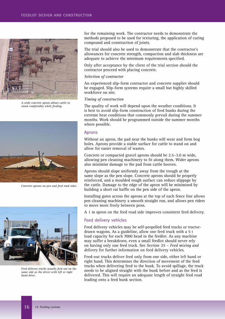
A wide concrete apron allows cattle to stand comfortably while feeding.
Feed delivery trucks usually feed out on the same side as the driver with left or right hand drive.
Concrete aprons on pen and feed road sides
17
FEEDLOT DESIGN AND CONSTRUCTION
19. Feeding systems
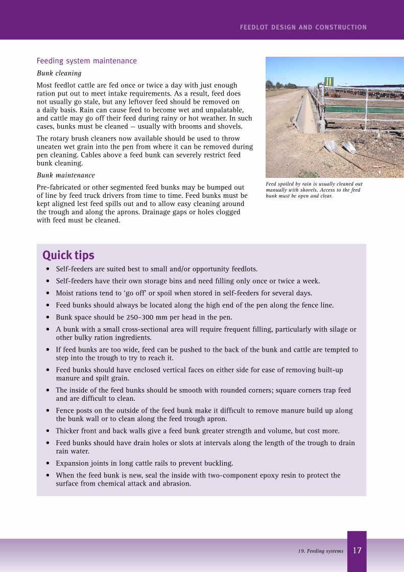
Feed spoiled by rain is usually cleaned out manually with shovels. Access to the feed bunk must be open and clear.
Feeding system maintenance
Bunk cleaning
Most feedlot cattle are fed once or twice a day with just enough ration put out to meet intake requirements. As a result, feed does not usually go stale, but any leftover feed should be removed on a daily basis. Rain can cause feed to become wet and unpalatable, and cattle may go off their feed during rainy or hot weather. In such cases, bunks must be cleaned — usually with brooms and shovels.
The rotary brush cleaners now available should be used to throw uneaten wet grain into the pen from where it can be removed during pen cleaning. Cables above a feed bunk can severely restrict feed bunk cleaning.
Bunk maintenance
Pre-fabricated or other segmented feed bunks may be bumped out of line by feed truck drivers from time to time. Feed bunks must be kept aligned lest feed spills out and to allow easy cleaning around the trough and along the aprons. Drainage gaps or holes clogged with feed must be cleaned.
Quick tips• Self-feeders are suited best to small and/or opportunity feedlots.
• Self-feeders have their own storage bins and need filling only once or twice a week.
• Moist rations tend to ‘go off’ or spoil when stored in self-feeders for several days.
• Feed bunks should always be located along the high end of the pen along the fence line.
• Bunk space should be 250–300 mm per head in the pen.
• A bunk with a small cross-sectional area will require frequent filling, particularly with silage or other bulky ration ingredients.
• If feed bunks are too wide, feed can be pushed to the back of the bunk and cattle are tempted to step into the trough to try to reach it.
• Feed bunks should have enclosed vertical faces on either side for ease of removing built-up manure and spilt grain.
• The inside of the feed bunks should be smooth with rounded corners; square corners trap feed and are difficult to clean.
• Fence posts on the outside of the feed bunk make it difficult to remove manure build up along the bunk wall or to clean along the feed trough apron.
• Thicker front and back walls give a feed bunk greater strength and volume, but cost more.
• Feed bunks should have drain holes or slots at intervals along the length of the trough to drain rain water.
• Expansion joints in long cattle rails to prevent buckling.
• When the feed bunk is new, seal the inside with two-component epoxy resin to protect the surface from chemical attack and abrasion.
18
FEEDLOT DESIGN AND CONSTRUCTION
19. Feeding systems
Further readingAUS-MEAT, 2011, NFAS Rules & Standards (April 2011), AUS-MEAT Limited, Brisbane, Qld.
DAFF, 2013, Australian Animal Standards and Guidelines for Cattle, Department of Agriculture, Forestry and Fisheries, Australian Government, Canberra, ACT.
MLA, 2012a, National Guidelines for Beef Cattle Feedlots in Australia. Meat & Livestock Australia, Sydney, NSW.
MLA, 2012b National Beef Cattle Feedlot Environmental Code of Practice. Meat & Livestock Australia, Sydney, NSW.
Guidelines for the establishment and operation of cattle feedlots in South Australia, Department of Primary Industries and Resources (SA) and Environment Protection Authority, 2006, Adelaide.
Victorian code for cattle feedlots, August 1995, Victorian Feedlot Commitee, Department of Agriculture, Energy & Minerals, Melbourne.
Skerman, A 2000, Reference manual for the establishment and operation of beef cattle feedlots in Queensland, Information Series QI99070, Queensland Cattle Feedlot Advisory Committee (FLAC), Department of Primary Industries, Toowoomba, QLD.
Guidelines for the Environmental Management of Beef Cattle Feedlots in Western Australia, Bulletin 4550, 2002, WADo Agriculture (ed.), Western Australia Department of Agriculture, Perth, WA.
The New South Wales Feedlot Manual, 1997, NSW Agriculture, NSW Agriculture, Department of Land and Water Conservation, Department of Urban Affairs and Planning & Environment Protection Authority, Orange.