Embed Size (px)
Citation preview

190
www.british-gypsum.com
5
Shaf
tWal
l ShaftWall
Shaft and duct encasement system
ShaftWall provides a lightweight,non-loadbearing fire-resistant structure to protect elements withinthe service cores of modern fast-track developments. It is alsoused to protect all forms of shaftsand ducts in conventional buildings.The system provides a protectivestructure which can be incorporatedat an early stage of the buildingbefore the building envelope issealed. The system can also be builthorizontally to provide a fire-ratedmembrane. StairWall is a derivativeof the ShaftWall system which is used to protect stairwells.

191
Technical support: T 0844 800 1991 F 0844 561 8816 E [email protected]
Shaf
tWal
l
5
Key facts
● Lightweight, fast-track construction
● Provides fire protective shaft enclosures,
stairwells and horizontal membranes
● Shaft enclosures built from one side only
● Horizontal membranes built entirely from below
● Can be installed prior to making the building
envelope weather-tight
● Minimal wall thickness from 80mm
1
Gypframe MF5 Ceiling Section
Gypframe Floor & Ceiling Channel
Gypframe 'I' Stud, Gypframe Retaining Channel
1
2
2
3
3

Take-offquantities1
as required
as required
as required
as required
Take-offquantities1
as required
as required
as required
www.british-gypsum.com
ComponentsGyproc and Glasroc board products
Gyproc FireLineThickness 12.5, 15mmWidth 1200mm
Gyproc FireLine MR
Thickness 12.5, 15mmWidth 1200mm
Gyproc CoreBoardThickness 19mmWidth 598mm
Gyproc DuraLineThickness 15mmWidth 1200mm
Gypframe Starter ChannelWidths 60 - 70, 92- 146mmLengths 3600 - 6000mmCodes 60 SC 55, 70 SC 70 and
92 SC 90, 146 TSC 90
Gypframe 'J' ChannelWidth 62mmLength 3600mmCodes 62 JC 70
Gypframe metal products
Gypframe 'I' StudsWidths 60 - 70, 92 - 146mmLengths 3600 - 6000mmCodes 60 I 70, 70 I 70 and
92 I 90, 146 TI 90
Gyp
Wal
l™ C
LASSIC
192
5
Shaf
tWal
l
1 The quantities required for ShaftWall vary significantly depending onthe dimensions of the installation and the performance specification ofthe system. Refer to section 11 - Quantity take-off details.
Gyp
Lyn
er™
UN
IVER
SA
L
193
Technical support: T 0844 800 1991 F 0844 561 8816 E [email protected]
Shaf
tWal
l
5
Gypframe metal products Gypframe metal poductsTake-off
quantities1
as required
as required
as required
as required
as required
Take-offquantities1
as required
as required
as required
as required
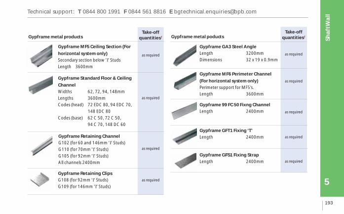
Gypframe Standard Floor & Ceiling
ChannelWidths 62, 72, 94, 148mmLengths 3600mmCodes (head) 72 EDC 80, 94 EDC 70,
148 EDC 80Codes (base) 62 C 50, 72 C 50,
94 C 70, 148 DC 60
Gypframe Retaining ClipsG108 (for 92mm 'I' Studs)G109 (for 146mm 'I' Studs)
Gypframe Retaining ChannelG102 (for 60 and 146mm 'I' Studs)G110 (for 70mm 'I' Studs)G105 (for 92mm 'I' Studs)All channels 2400mm
Gypframe GA3 Steel AngleLength 3200mmDimensions 32 x 19 x 0.9mm
Gypframe 99 FC 50 Fixng ChannelLength 2400mm
Gypframe GFT1 Fixing ‘T’Length 2400mm
Gypframe GFS1 Fixing StrapLength 2400mm
Gypframe MF5 Ceiling Section (For
horizontal system only)Secondary section below 'I' StudsLength 3600mm
Gypframe MF6 Perimeter Channel
(For horizontal system only)Perimeter support for MF5’s.Length 3600mm

Take-offquantities1
as required
as required
as required
as required
as required
Take-offquantities1
as required
as required
as required
10m2 per
25kg bag
10m2 per
25kg bag
11m2 per
25kg bag
www.british-gypsum.com
ComponentsFixing and finishing products Fixing and finishing products
Thistle Multi-Finish or Thistle Board Finish To provide a plaster skim finish.or
Gyp
Wal
l™ C
LASSIC
194
5
Shaf
tWal
l
Gyproc Drywall ScrewsFor fixing boards to stud framing up to0.79mm thick.
Gyproc Jack-Point ScrewsFor fixing boards to stud framing0.8mm thick or greater and ‘I’ studsgreather than 0.55mm thick.
Gypframe Wafer Head Jack-PointScrewsFor metal-to-metal fixing 0.8mm thickor greater and ‘I’ studs greather than0.55mm thick.
Isover APR 1200For enhanced acoustic performance.
Gyproc CoreBoard Dimensions 19 x 68 x 598mm
and 19 x 122 x 598mm
Gyproc SealantSealing air paths to achieve optimumsound insulation and sealing air shafts.
Gyproc jointing materialsFor a seamless finish.
Thistle Durafinish To provide improved resistance toaccidental damage.or
Thistle Spray FinishGypsum finish plaster for spray orhand application.
1 The quantities required for ShaftWall vary significantly depending onthe dimensions of the insulation and the performance specification ofthe system. Refer to section 11 - Quantity take-off details.
Gyproc FireStripFor sealing deflection heads.

Technical support: T 0844 800 1991 F 0844 561 8816 E [email protected]
Gyp
Lyn
er™
UN
IVER
SA
L
195
Shaf
tWal
l
5
Construction tips
● The following points should be considered in addition to the construction tips for GypWall CLASSIC
● The estimated construction time is 1.5m2 - 2m2 / man hour (single layer wall with deflection head) or 1m2 - 1.5m2 / man
hour (double layer wall with deflection head) ready for finishing
● If the building envelope is left unsealed while ShaftWall is under construction, Gyproc FireLine MR should be used for
the lining
● The use of pressure conditions in various types of shaft / duct requires that the boards should be sealed into the
framing members using Gyproc Sealant in addition to the normal sealing of the framing to adjoining structures. It is
essential that these areas are identified at a very early stage of the contract and that other trades are instructed to
recognise the need for application of sealant and its replacement if subsequently damaged or removed
● If possible, plan the ShaftWall layout off the line of structural steelwork. This avoids special detailing such as fire
protected Z bars
● The floor track must have continuous support from the structure

www.british-gypsum.com
Installation
Construction tips (cont’d)
● In high usage areas the face lining of Gyproc FireLine can be substituted
by Gyproc DuraLine to provide a high impact resistant lining. Fire
resistance will not be compromised provided that an equivalent
minimum thickness of board is used
● If required for aesthetic reasons, it is permitted to fix an additional layer
of 12.5mm Gyproc WallBoard to the exposed stud flanges on the shaft
side to provide a smooth, seamless surface
The following procedure relates to a60mm framework, with a 15mmdeflection head. Specific references aremade where the procedure for 70mm,92mm or 146mm frameworks differsfrom this. The wall is installed from theroom side in one direction.
Gyp
Wal
l™ C
LASSIC
196
5
Shaf
tWal
l
1
Technical support: T 0844 800 1991 F 0844 561 8816 E [email protected]
Gyp
Lyn
er™
UN
IVER
SA
L
197
Shaf
tWal
l
5
4
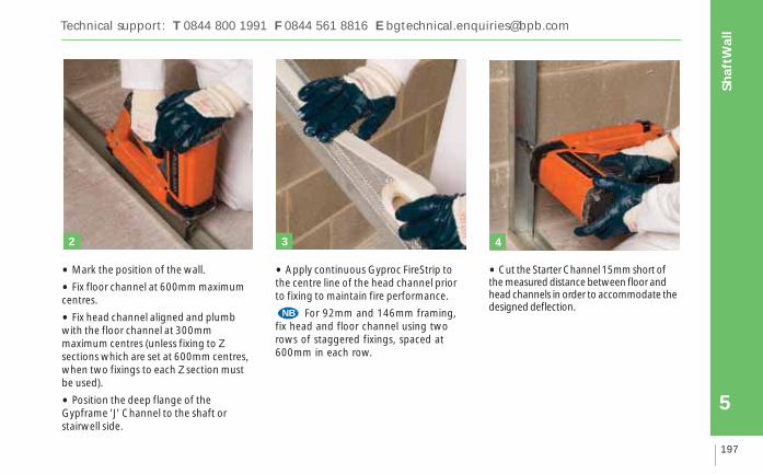
• Mark the position of the wall.
• Fix floor channel at 600mm maximumcentres.
• Fix head channel aligned and plumbwith the floor channel at 300mmmaximum centres (unless fixing to Zsections which are set at 600mm centres,when two fixings to each Z section mustbe used).
• Position the deep flange of theGypframe 'J' Channel to the shaft orstairwell side.
• Apply continuous Gyproc FireStrip tothe centre line of the head channel priorto fixing to maintain fire performance.
For 92mm and 146mm framing,fix head and floor channel using tworows of staggered fixings, spaced at600mm in each row.
•Cut the Starter Channel 15mm short ofthe measured distance between floor andhead channels in order to accommodate thedesigned deflection.
NB
2 3
www.british-gypsum.comG
ypW
all™
CLA
SSIC
198
5
Shaf
tWal
l
7
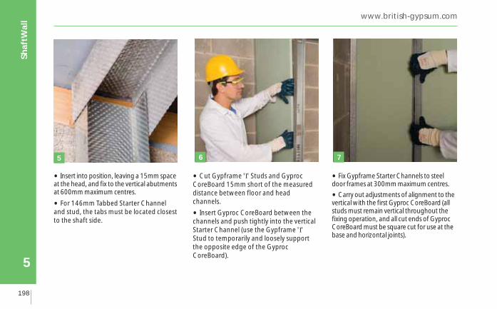
• Insert into position, leaving a 15mm spaceat the head, and fix to the vertical abutmentsat 600mm maximum centres.
• For 146mm Tabbed Starter Channeland stud, the tabs must be located closestto the shaft side.
• Cut Gypframe 'I' Studs and GyprocCoreBoard 15mm short of the measureddistance between floor and headchannels.
• Insert Gyproc CoreBoard between thechannels and push tightly into the verticalStarter Channel (use the Gypframe 'I'Stud to temporarily and loosely supportthe opposite edge of the GyprocCoreBoard).
• Fix Gypframe Starter Channels to steeldoor frames at 300mm maximum centres.
•Carry out adjustments of alignment to thevertical with the first Gyproc CoreBoard (allstuds must remain vertical throughout thefixing operation, and all cut ends of GyprocCoreBoard must be square cut for use at thebase and horizontal joints).
5 6

8
Technical support: T 0844 800 1991 F 0844 561 8816 E [email protected]
9
Gyp
Lyn
er™
UN
IVER
SA
L
199
Shaf
tWal
l
5
• Fix two 19mm x 122mm GyprocCoreBoard fire-stops (cut on site) betweenthe webs and behind the vertical flangesof the studs and into the head channel(see Junction details – deflectionheads).
• For 92mm and 146mm frameworkstwo head details are available for each.The simplified detail incorporating aGypframe Retaining Clip accommodatesdeflection in respect of initial buildingsettlement. Fix as follows:
• Friction fit a Retaining Clip into the topflanges of each Gypframe 'I' Stud so as toretain a single Gyproc CoreBoard fire-stopwithin the head channel. Use theGypframe G108 component with 92mmframing and Gypframe G109 with146mm framing.
• The alternative head detail canaccommodate deflection due to liveloads. This adopts a dropped soffit anduses two Gyproc CoreBoard fire-stops (cuton site) fixed horizontally to the web ofthe head channel. Use 19mm x 50mmwith a 70mm framework, use 19mm x68mm fire-stops with a 92mm frameworkand 19mm x 122mm fire-stops with a146mm framework (see Junction details– deflection heads).
Retaining Clip
Temporarylocating screw

www.british-gypsum.comG
ypW
all™
CLA
SSIC
200
5
Shaf
tWal
l
11
• Position Gypframe G102 RetainingChannel in the Starter Channel (useGypframe G110 Retaining Channel in thecase of a 70mm framework andGypframe G105 Retaining Channel in thecase of a 92mm framework).
• Ensure that the Gypframe G102Retaining Channel is securely located inthe tabs when using 146mm framing.
• Push the Gypframe 'I' Stud into itspermanent position to secure the firstsection of core boards.
• To simplify the installation of the finalGyproc CoreBoard when workingbetween fixed points, cut boards to therequired width, (minimum 300mm), less10mm fitting tolerance. Insert the boardsby twisting the flange of the last stud.
10
Tabs in 'I' stud
‘turned down’

1412
Technical support: T 0844 800 1991 F 0844 561 8816 E [email protected]
13
Gyp
Lyn
er™
UN
IVER
SA
L
201
Shaf
tWal
l
5
• Fire-stop horizontal joints betweenGyproc CoreBoard using a 19mm x122mm Gyproc CoreBoard fire-stop (cuton site). Fix the fire-stop to Gypframe GA3Steel Angle using three Gyproc Jack-PointScrews, and beads of sealant top andbottom.
Before lining board fixing commences, inspect the GyprocCoreBoard to ensure that all componentsincluding fire-stops are correctly located.Apply Gyproc Sealant in the angle formedby the perimeter framing structure.
Board fixing
• Screw-fix tapered edge Gyproc FireLinebase layer boards at 300mm centres to allframing members.
• Screw-fix outer layer boards to allframing members at 300mm centres(200mm at external angles) and staggerboard joints between layers.
NB
Fire-stopping to horizontal Gyproc
CoreBoard joints - Mechanical fix
Gypframe
GA3
Steel Angle

www.british-gypsum.comG
ypW
all™
CLA
SSIC
202
5
Shaf
tWal
l
1615
• Where there is a horizontal joint in thelining boards, stagger end joints by600mm minimum between layers.
• Cut lining boards 15mm short to allowfor the deflection. Do not fix into theflange of the head channel (see Junctiondetails – deflection heads)
• Install Gypframe GFT1 Fixing 'T' tosupport the end joints of single layerboards. Fix Gypframe GFS1 Fixing Strapinstead in double layer boarding betweenboard layers.
• Insert screws at 300mm centres.

18
Technical support: T 0844 800 1991 F 0844 561 8816 E [email protected]
17
Gyp
Lyn
er™
UN
IVER
SA
L
203
Shaf
tWal
l
5
Services
• Penetrations of ShaftWall by services,ducts, control joints and general openingswill require careful detailing. This is toensure that the penetration does notimpair the fire resistance of the wall or actas a mechanism of fire spread. Specificconstruction details should be determinedby the designer.
Airshafts
Where ShaftWall is used to enclose airpressure ducts, Gyproc Sealant is used toseal potential airpaths (see Junctiondetails – Sealing air shafts and serviceducts).
• Apply sealant to the inside face of therear flanges of Gypframe 'I' Studs, headchannel, floor channel and GypframeStarter Channels.
• Seal Gyproc CoreBoard fire-stops,which are located over the horizontaljoints in Gyproc CoreBoard, by applyingbeads of Gyproc Sealant prior to fixing.
• Seal the first layer lining boards to theframework, applying Gyproc Sealant onlyto the face flange of the perimeterchannels.
www.british-gypsum.comG
ypW
all™
CLA
SSIC
204
5
Shaf
tWal
l
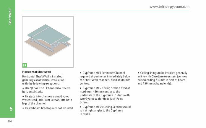
Horizontal ShaftWall
Horizontal ShaftWall is installedgenerally as for vertical installation with the following exceptions.
• Use 'JC' or 'EDC' Channels to receivehorizontal studs.
• Fix studs into channels using GyprocWafer Head Jack-Point Screws, into bothlegs of the channel.
• Plasterboard fire-stops are not required.
• Gypframe MF6 Perimeter Channelrequired at perimeter, immediately belowthe ShaftWall channels, fixed at 600mmcentres.
• Gypframe MF5 Ceiling Section fixed atmaximum 450mm centres to theunderside of the Gypframe 'I' Studs withtwo Gyproc Wafer Head Jack-PointScrews.
• Gypframe MF5’s Ceiling Section shouldrun at right angles to the Gypframe 'I' Studs.
• Ceiling linings to be installed generallyin line with CasoLine MF system (centresnot exceeding 230mm in field of boardand 150mm at board ends).
19

Technical support: T 0844 800 1991 F 0844 561 8816 E [email protected]
Gyp
Lyn
er™
UN
IVER
SA
L
205
Shaf
tWal
l
5
Junction details - general
2
1
3
Gypframe 'I' StudGyproc CoreBoardGypframe Retaining Channel
Gyproc FireLine / Gyproc DuraLine123
4
20 Intermediate stud 21 Abutting partition (on stud)
4
2
1
3
4
21
3
5
4
Gyp
Wal
l™ C
LASSIC
206
5
Shaf
tWal
l www.british-gypsum.com
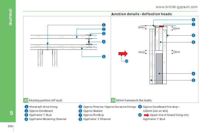
Metal self-drive fixingGyproc CoreBoardGypframe 'I' StudGypframe Retaining Channel
Gyproc FireLine / Gyproc DuraLine liningsGyproc SealantGyproc FireStripGypframe 'J' Channel
Gyproc CoreBoard fire-stop –122mm (cut on site)
Upper line of board fixing intoGypframe 'I' Stud
1234
5
22 Abutting partition (off stud) 23 60mm framework (live loads).
15mm
15mm
15mm
15mm
Junction details - deflection heads
6
678
9
7
5
8
9
4
10
10

Technical support: T 0844 800 1991 F 0844 561 8816 E [email protected]
Gyp
Lyn
er™
UN
IVER
SA
L
207
Shaf
tWal
l
5
24 70mm framework (live loads). 25 92mm framework (not suitable for live loads).
Gyproc SealantGyproc FirestripGypframe Extra Deep Flange Floor & Ceiling ChannelGyproc CoreBoard fire-stop 122mm
deep (cut on site)Gyproc CoreBoardGypframe Retaining ChannelGyproc FireLine / Gyproc DuraLine linings
Upper line of board fixing into
Gypframe 'I' StudGypframe G108 Retaining ClipGyproc CoreBoard fire-stop nominally50mm wide (cut on site)Gyproc CoreBoard as dropped soffit
123
4
5
78
15mm
15mm
15mm
15mm
8
2
1
3
9
4
9
5
6
7
6
3
6
7
15mm
15mm
15mm
15mm
21
8
10
11
5
11
10

Gyp
Wal
l™ C
LASSIC
208
5
Shaf
tWal
l www.british-gypsum.com
26 92mm framework (live loads). 27 146mm framework (not suitable for live loads).
10
Gyproc SealantGyproc FireStripGyproc CoreBoard as dropped soffitGypframe Extra Deep Flange Floor &Ceiling Channel
Gyproc CoreBoard fire-stop –122mm deep (cut on site) Gyproc Core BoardGypframe Retaining ChannelGyproc FireLine / Gyproc DuraLine linings
Gypframe G109 Retaining ClipUpper line of board fixing into
Gypframe 'I' StudGyproc CoreBoard fire-stops nominally68mm wide (cut on site)
123
5
8
610
74
9
15mm
15mm
15mm
15mm 15mm 15mm
15mm10
1
23
4
11
6
7
8
1
2
5
4
69
7
8
Junction details - deflection heads (cont’d)
15mm
11

Technical support: T 0844 800 1991 F 0844 561 8816 E [email protected]
Gyp
Lyn
er™
UN
IVER
SA
L
209
Shaf
tWal
l
5
28 146mm framework (live loads).
9
Gyproc SealantGyproc FireStripGyproc CoreBoard as dropped soffitGyproc CoreBoard fire-stop –122mm (cut on site)
Gypframe Extra Deep Flange Floor &Ceiling ChannelGyproc CoreBoardGypframe Retaining Channel
Gyproc FireLine / Gyproc DuraLine liningsUpper line of board fixing into
Gypframe 'I' Stud
1234
5
67
89
1
2
34
5
6
7
8
15mm
15mm
15mm
15mm

Gyp
Wal
l™ C
LASSIC
210
5
Shaf
tWal
l www.british-gypsum.com
Gypframe 'J' Channel (to frame theopening)Gyproc Profilex Access Panel
Gypframe 'I' StudsGyproc CoreBoardGyproc FireLine / Gyproc DuraLine lining
Gypframe Retaining Channel1
2
34
29 Opening between studs
Section YY
Section ZZ
Y
Y
Z Z
5
6
3
4
6
1
2
5
Junction details - Gyproc Profilex Access Panel
Technical support: T 0844 800 1991 F 0844 561 8816 E [email protected]
Gyp
Lyn
er™
UN
IVER
SA
L
211
Shaf
tWal
l
5
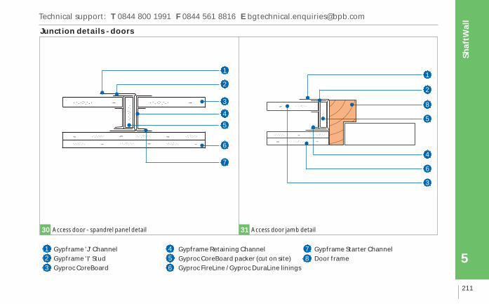
Junction details - doors
1
3
2
5
4
1
8
2
Gypframe 'J' ChannelGypframe 'I' StudGyproc CoreBoard
Gypframe Retaining ChannelGyproc CoreBoard packer (cut on site)Gyproc FireLine / Gyproc DuraLine linings
Gypframe Starter ChannelDoor frame
123
45
30 Access door - spandrel panel detail 31 Access door jamb detail
6
78
6
7
5
4
6
3

Gyp
Wal
l™ C
LASSIC
212
5
Shaf
tWal
l www.british-gypsum.com
7
2
4
5
1
1
6
3
32 Lift door (Gypframe Starter Channel mechanically fixed to frame). 33 Sealing head (pressurised system).
Gyproc SealantGyproc CoreBoardGypframe Retaining Channel
Gypframe Starter ChannelGyproc FireLine / Gyproc DuraLine liningsGyproc FireStrip
Gypframe 'J' ChannelGyproc CoreBoard fire-stop (cut on site)
123
456
78
8
2
5
3
Junction details - sealing air shafts & service ducts

Technical support: T 0844 800 1991 F 0844 561 8816 E [email protected]
Gyp
Lyn
er™
UN
IVER
SA
L
213
Shaf
tWal
l
5
6
4
2
3
5
1
2
5
Gypframe 'I' StudGyproc CoreBoardGyproc FireLine / Gyproc DuraLine linings
Gypframe Floor & Ceiling ChannelGyproc SealantGypframe Retaining Channel
123
45
34Base detail (Gyproc CoreBoard only requires sealing into channelfor pressurised system). 35
Sealing of Gyproc CoreBoards to Gypframe 'I' Stud (pressurised system).
6
6
3
5
Gyp
Wal
l™ C
LASSIC
214
5
Shaf
tWal
l www.british-gypsum.com
6
2
1
4
3
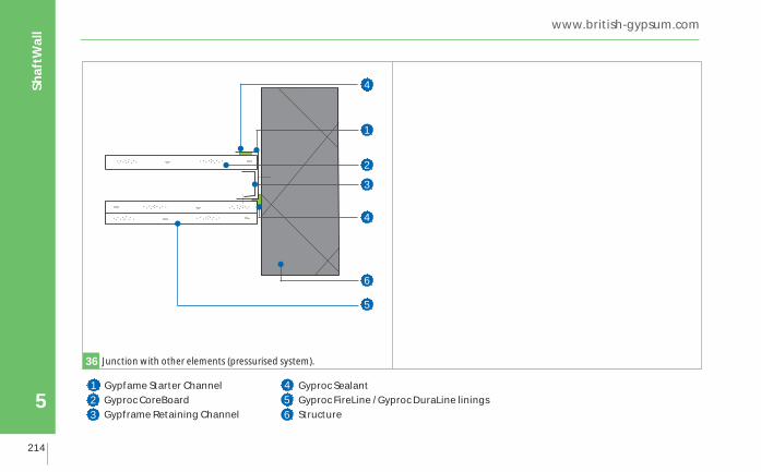
Gypfame Starter ChannelGyproc CoreBoardGypframe Retaining Channel
Gyproc SealantGyproc FireLine / Gyproc DuraLine liningsStructure
123
45
36 Junction with other elements (pressurised system).
6
4
5

Technical support: T 0844 800 1991 F 0844 561 8816 E [email protected]
Gyp
Lyn
er™
UN
IVER
SA
L
215
Shaf
tWal
l
5