Embed Size (px)
Citation preview
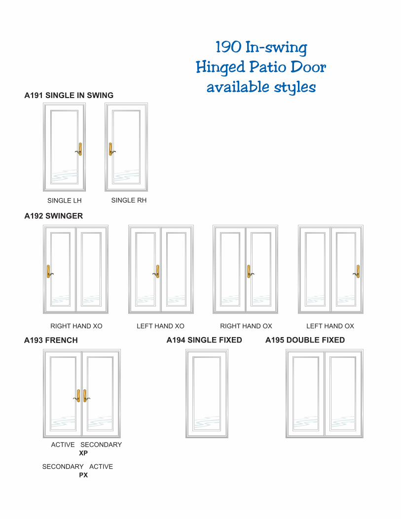
190 In-swing Hinged Patio Door
available styles
Manufacturer of Alpine Window Products
SINGLE RHSINGLE LH
A191 SINGLE IN SWING
RIGHT HAND XO
ACTIVE
A192 SWINGER
A193 FRENCH
LEFT HAND XO RIGHT HAND OX LEFT HAND OX
SECONDARY
XP
SECONDARY ACTIVE
PX
A194 SINGLE FIXED A195 DOUBLE FIXED
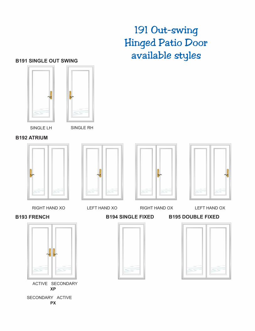
191 Out-swing Hinged Patio Door
available styles
Manufacturer of Alpine Window Products
SINGLE RHSINGLE LH
B191 SINGLE OUT SWING
RIGHT HAND XO
ACTIVE
B192 ATRIUM
B193 FRENCH
LEFT HAND XO RIGHT HAND OX LEFT HAND OX
SECONDARY
XP
SECONDARY ACTIVE
PX
B194 SINGLE FIXED B195 DOUBLE FIXED
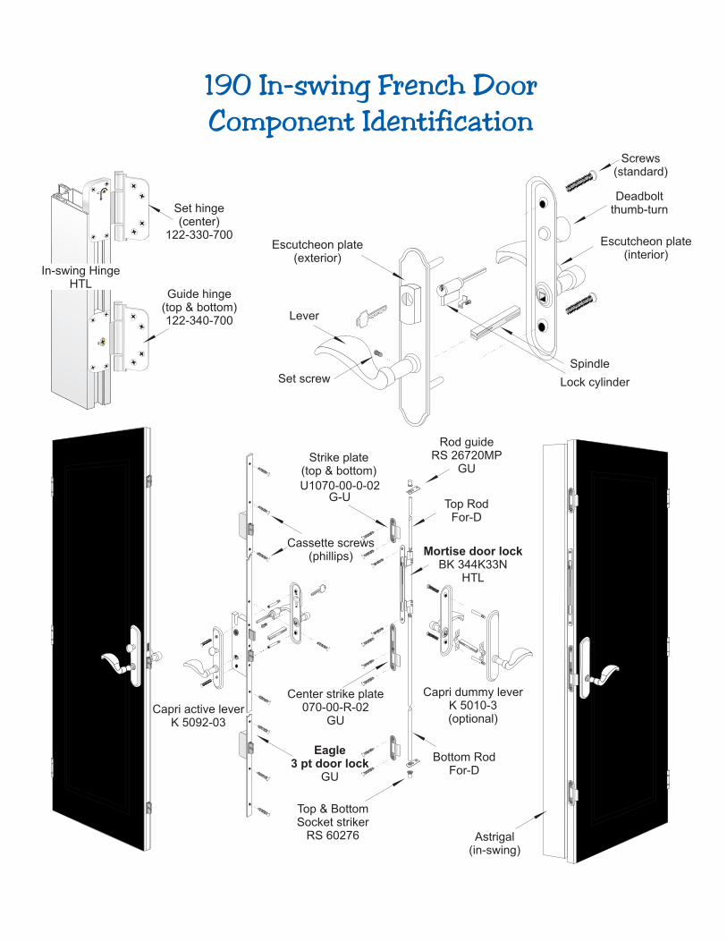
Top & BottomSocket striker
RS 60276
Center strike plate070-00-R-02
GU
Strike plate(top & bottom)
U1070-00-0-02G-U
Mortise door lockBK 344K33N
HTL
Rod guideRS 26720MP
GU
Top RodFor-D
Eagle3 pt door lock
GU
Guide hinge(top & bottom)122-340-700
Set hinge(center)
122-330-700
In-swing HingeHTL
Bottom RodFor-D
Capri dummy leverK 5010-3(optional)
Capri active leverK 5092-03
Cassette screws(phillips)
Astrigal(in-swing)
190 In-swing French DoorComponent Identification
Escutcheon plate(exterior)
Deadboltthumb-turn
Lock cylinder
Escutcheon plate(interior)
Lever
Spindle
Screws(standard)
Set screw
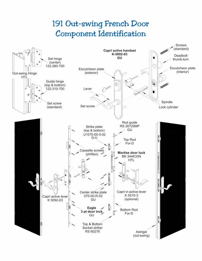
Set hinge(center)
122-280-700
Guide hinge(top & bottom)122-310-700
Strike plate(top & bottom)
U1070-00-0-02G-U
Rod guideRS 26720MP
GU
Top RodFor-D
Mortise door lockBK 344K33N
HTL
Top & BottomSocket striker
RS 60276
Bottom RodFor-D
Capri active handsetK-5092-03
GU
Out-swing HingeHTL
Capri in-active leverK 5010-3(optional)
Capri active leverK 5092-03
Set screw(standard)
Cassette screws(phillips)
Center strike plate070-00-R-02
GU
Astrigal(out-swing)
Eagle3 pt door lock
GU
191 Out-swing French DoorComponent Identification
Escutcheon plate(exterior)
Deadboltthumb-turn
Lock cylinder
Escutcheon plate(interior)
Lever
Spindle
Screws(standard)
Set screw
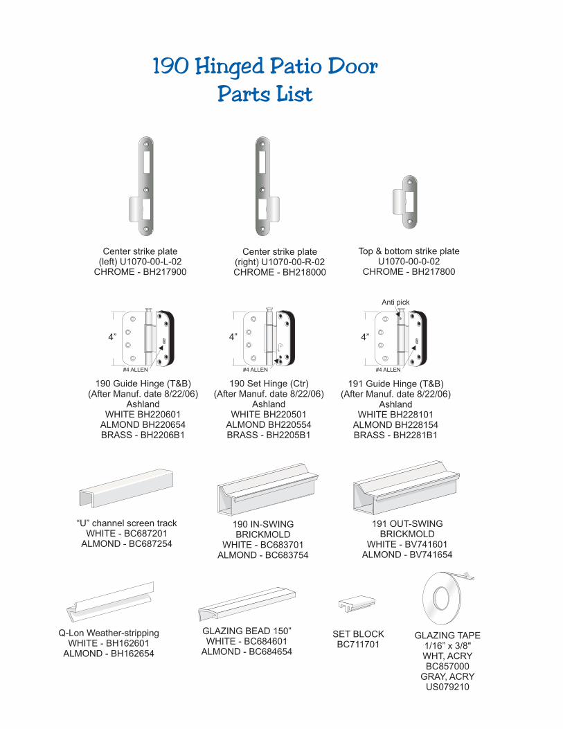
190 Hinged Patio DoorParts List
Center strike plate(left) U1070-00-L-02
CHROME - BH217900
Center strike plate(right) U1070-00-R-02CHROME - BH218000
Top & bottom strike plateU1070-00-0-02
CHROME - BH217800
191 OUT-SWINGBRICKMOLD
WHITE - BV741601ALMOND - BV741654
Q-Lon Weather-strippingWHITE - BH162601
ALMOND - BH162654
GLAZING BEAD 150”WHITE - BC684601
ALMOND - BC684654
190 IN-SWING BRICKMOLD
WHITE - BC683701ALMOND - BC683754
“U” channel screen trackWHITE - BC687201
ALMOND - BC687254
SET BLOCKBC711701
4” 4”
190 Guide Hinge (T&B)(After Manuf. date 8/22/06)
AshlandWHITE BH220601
ALMOND BH220654BRASS - BH2206B1
190 Set Hinge (Ctr)(After Manuf. date 8/22/06)
AshlandWHITE BH220501
ALMOND BH220554BRASS - BH2205B1
#4 ALLEN #4 ALLEN
4”
191 Guide Hinge (T&B)(After Manuf. date 8/22/06)
AshlandWHITE BH228101
ALMOND BH228154BRASS - BH2281B1
#4 ALLEN
Anti pick
GLAZING TAPE1/16” x 3/8"WHT, ACRYBC857000
GRAY, ACRYUS079210
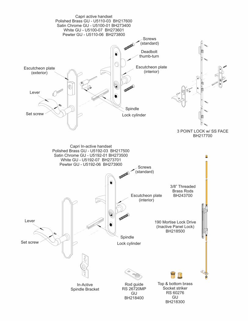
Escutcheon plate(exterior)
Deadboltthumb-turn
Lock cylinder
Escutcheon plate(interior)
Lever
Spindle
Screws(standard)
Capri active handsetPolished Brass GU - U5110-03 BH217600Satin Chrome GU - U5100-01 BH273400
White GU - U5100-07 BH273601Pewter GU - U5110-06 BH273800
Set screw
3 POINT LOCK w/ SS FACEBH217700
190 Mortise Lock Drive(Inactive Panel Lock)
BH218500
3/8” ThreadedBrass RodsBH243700
Lock cylinder
Escutcheon plate(interior)
Lever
Spindle
Screws(standard)
Set screw
Capri active handsetPolished Brass GU - U5192-03 BH217500Satin Chrome GU - U5192-01 BH273500
White GU - U5192-07 BH273701Pewter GU - U5192-06 BH273900
In-
In-ActiveSpindle Bracket
Rod guideRS 26720MP
GUBH218400
Top & bottom brassSocket striker
RS 60276GU
BH218300
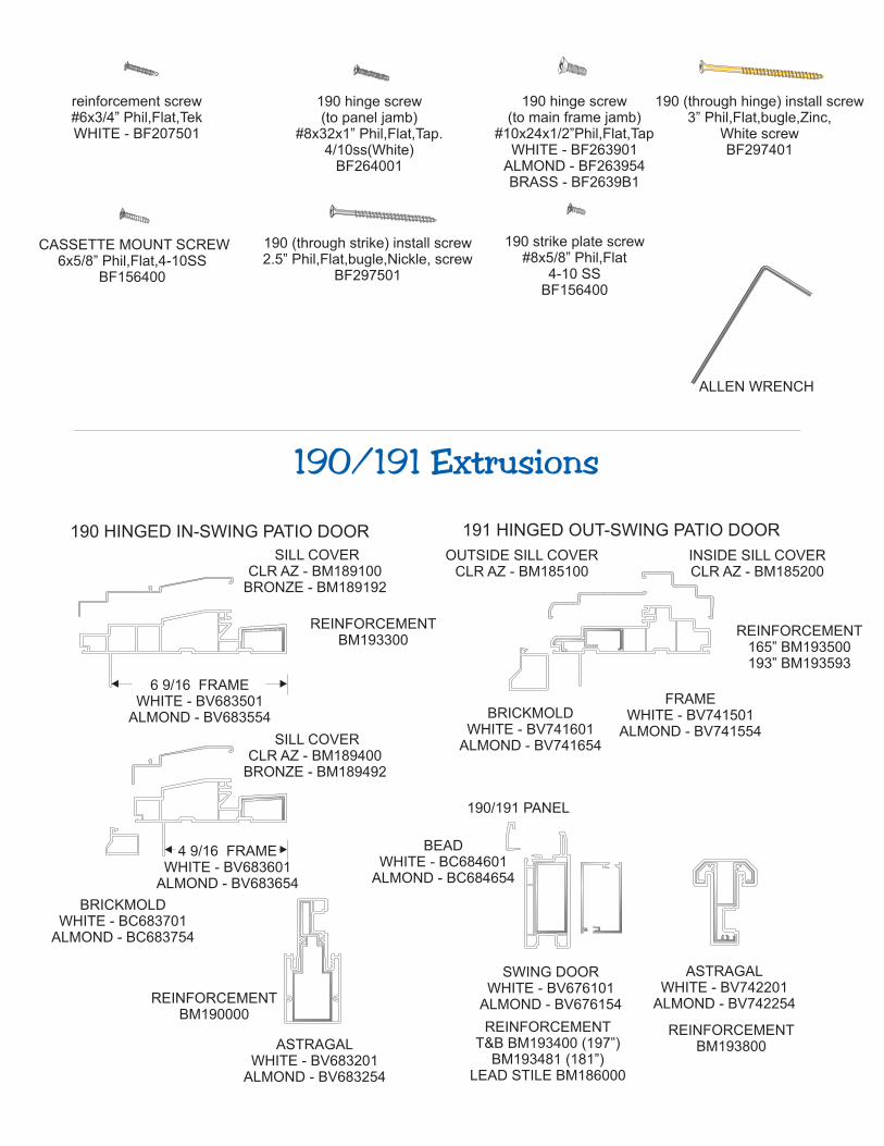
reinforcement screw#6x3/4” Phil,Flat,TekWHITE - BF207501
CASSETTE MOUNT SCREW6x5/8” Phil,Flat,4-10SS
BF156400
190 hinge screw(to panel jamb)
#8x32x1” Phil,Flat,Tap.4/10ss(White)
BF264001
190 (through hinge) install screw3” Phil,Flat,bugle,Zinc,
White screwBF297401
190 (through strike) install screw2.5” Phil,Flat,bugle,Nickle, screw
BF297501
190 hinge screw (to main frame jamb)
#10x24x1/2”Phil,Flat,TapWHITE - BF263901
ALMOND - BF263954BRASS - BF2639B1
6 9/16 FRAMEWHITE - BV683501
ALMOND - BV683554
4 9/16 FRAMEWHITE - BV683601
ALMOND - BV683654
BRICKMOLDWHITE - BC683701
ALMOND - BC683754
ASTRAGALWHITE - BV683201
ALMOND - BV683254
BRICKMOLDWHITE - BV741601
ALMOND - BV741654
ASTRAGALWHITE - BV742201
ALMOND - BV742254
FRAMEWHITE - BV741501
ALMOND - BV741554
SWING DOORWHITE - BV676101
ALMOND - BV676154
BEADWHITE - BC684601
ALMOND - BC684654
191 HINGED OUT-SWING PATIO DOOR190 HINGED IN-SWING PATIO DOOR
190/191 Extrusions
OUTSIDE SILL COVERCLR AZ - BM185100
INSIDE SILL COVERCLR AZ - BM185200
SILL COVERCLR AZ - BM189100
BRONZE - BM189192
SILL COVERCLR AZ - BM189400
BRONZE - BM189492
190/191 PANEL
ALLEN WRENCH
190 strike plate screw#8x5/8” Phil,Flat
4-10 SSBF156400
REINFORCEMENTBM193300
REINFORCEMENTT&B BM193400 (197”)
BM193481 (181”)LEAD STILE BM186000
REINFORCEMENT165” BM193500193” BM193593
REINFORCEMENTBM193800
REINFORCEMENTBM190000
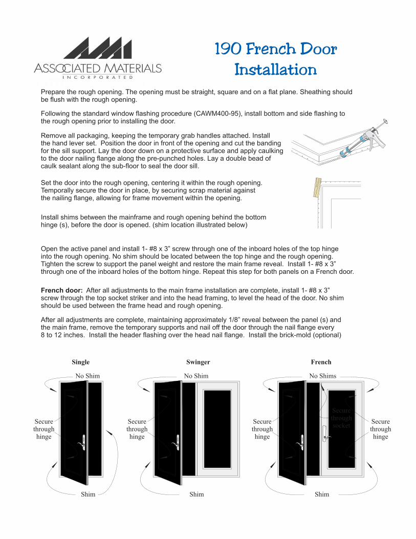
Prepare the rough opening. The opening must be straight, square and on a flat plane. Sheathing shouldbe flush with the rough opening.
Install shims between the mainframe and rough opening behind the bottom hinge (s), before the door is opened. (shim location illustrated below)
Remove all packaging, keeping the temporary grab handles attached. Install the hand lever set. Position the door in front of the opening and cut the banding for the sill support. Lay the door down on a protective surface and apply caulking to the door nailing flange along the pre-punched holes. Lay a double bead ofcaulk sealant along the sub-floor to seal the door sill.
Following the standard window flashing procedure (CAWM400-95), install bottom and side flashing tothe rough opening prior to installing the door.
Set the door into the rough opening, centering it within the rough opening. Temporally secure the door in place, by securing scrap material against the nailing flange, allowing for frame movement within the opening.
French door: After all adjustments to the main frame installation are complete, install 1- #8 x 3”screw through the top socket striker and into the head framing, to level the head of the door. No shimshould be used between the frame head and rough opening.
After all adjustments are complete, maintaining approximately 1/8” reveal between the panel (s) andthe main frame, remove the temporary supports and nail off the door through the nail flange every 8 to 12 inches. Install the header flashing over the head nail flange. Install the brick-mold (optional)
Open the active panel and install 1- #8 x 3” screw through one of the inboard holes of the top hinge into the rough opening. No shim should be located between the top hinge and the rough opening. Tighten the screw to support the panel weight and restore the main frame reveal. Install 1- #8 x 3” through one of the inboard holes of the bottom hinge. Repeat this step for both panels on a French door.
Shim
FrenchSwingerSingle
No Shims
Securethroughhinge
Securethroughhinge
Securethroughsocket
Shim
No Shim
Securethroughhinge
Shim
No Shim
Securethroughhinge
Manufacturer of Alpine Window Products
190 French DoorInstallation
Shim
Shim
No Shim
Center Hinge
Top & Bottom Hinge
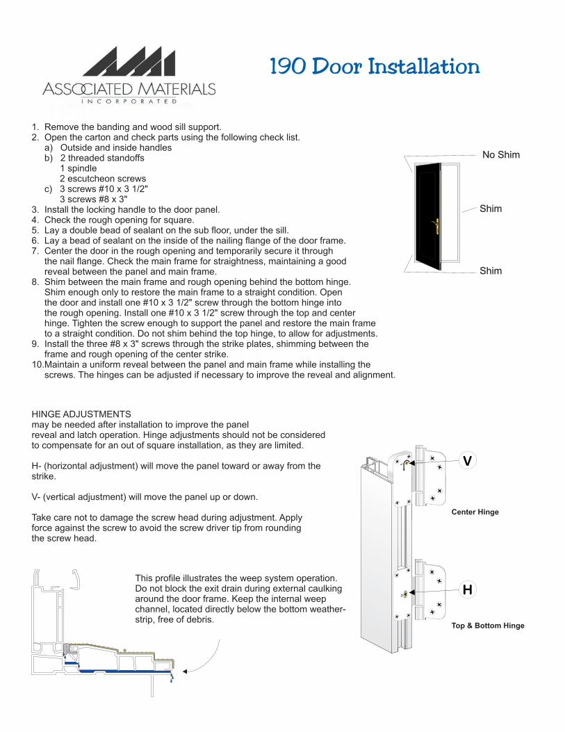
HINGE ADJUSTMENTSmay be needed after installation to improve the panelreveal and latch operation. Hinge adjustments should not be consideredto compensate for an out of square installation, as they are limited.
H- (horizontal adjustment) will move the panel toward or away from thestrike.
V- (vertical adjustment) will move the panel up or down.
Take care not to damage the screw head during adjustment. Applyforce against the screw to avoid the screw driver tip from roundingthe screw head.
This profile illustrates the weep system operation.Do not block the exit drain during external caulkingaround the door frame. Keep the internal weepchannel, located directly below the bottom weather-strip, free of debris.
1. Remove the banding and wood sill support.2. Open the carton and check parts using the following check list. a) Outside and inside handles b) 2 threaded standoffs 1 spindle 2 escutcheon screws c) 3 screws #10 x 3 1/2" 3 screws #8 x 3"3. Install the locking handle to the door panel.4. Check the rough opening for square.5. Lay a double bead of sealant on the sub floor, under the sill.6. Lay a bead of sealant on the inside of the nailing flange of the door frame.7. Center the door in the rough opening and temporarily secure it through the nail flange. Check the main frame for straightness, maintaining a good reveal between the panel and main frame.8. Shim between the main frame and rough opening behind the bottom hinge. Shim enough only to restore the main frame to a straight condition. Open the door and install one #10 x 3 1/2" screw through the bottom hinge into the rough opening. Install one #10 x 3 1/2" screw through the top and center hinge. Tighten the screw enough to support the panel and restore the main frame to a straight condition. Do not shim behind the top hinge, to allow for adjustments.9. Install the three #8 x 3" screws through the strike plates, shimming between the frame and rough opening of the center strike.10.Maintain a uniform reveal between the panel and main frame while installing the screws. The hinges can be adjusted if necessary to improve the reveal and alignment.
Manufacturer of Alpine Window Products
190 Door Installation
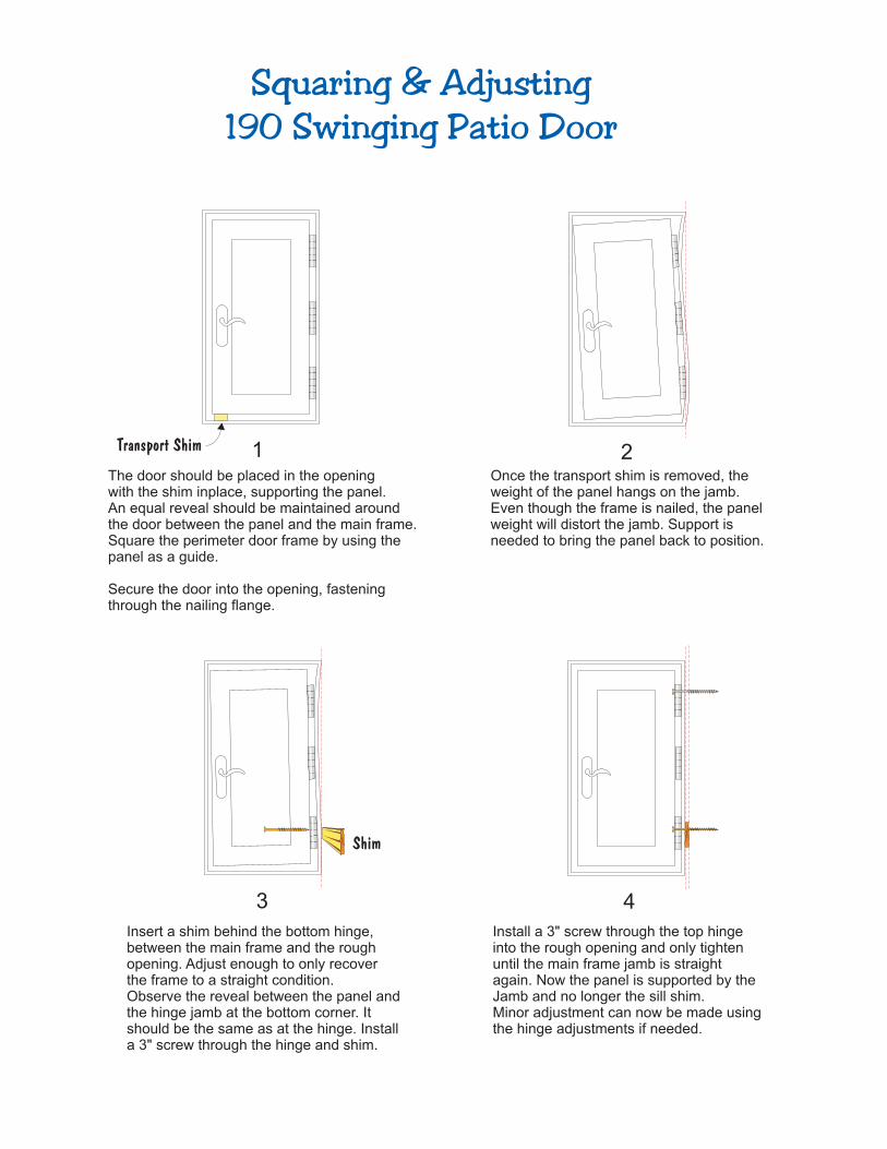
1The door should be placed in the openingwith the shim inplace, supporting the panel.An equal reveal should be maintained aroundthe door between the panel and the main frame.Square the perimeter door frame by using the panel as a guide.
Secure the door into the opening, fasteningthrough the nailing flange.
2Once the transport shim is removed, theweight of the panel hangs on the jamb.Even though the frame is nailed, the panelweight will distort the jamb. Support isneeded to bring the panel back to position.
4
Install a 3" screw through the top hingeinto the rough opening and only tightenuntil the main frame jamb is straightagain. Now the panel is supported by theJamb and no longer the sill shim.Minor adjustment can now be made using the hinge adjustments if needed.
3
Insert a shim behind the bottom hinge, between the main frame and the rough opening. Adjust enough to only recover the frame to a straight condition.Observe the reveal between the panel andthe hinge jamb at the bottom corner. Itshould be the same as at the hinge. Installa 3" screw through the hinge and shim.
Squaring & Adjusting190 Swinging Patio Door
Manufacturer of Alpine Window Products
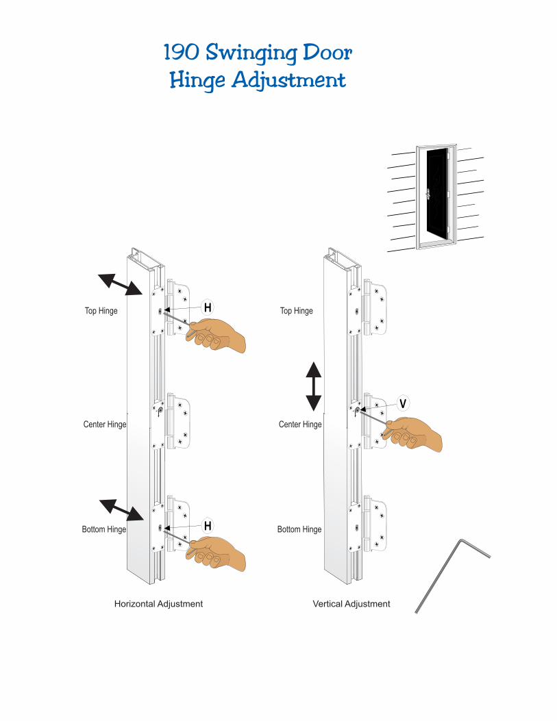
Bottom Hinge Bottom Hinge
Top Hinge Top Hinge
Center Hinge Center Hinge
Horizontal Adjustment Vertical Adjustment
190 Swinging DoorHinge Adjustment
Manufacturer of Alpine Window Products
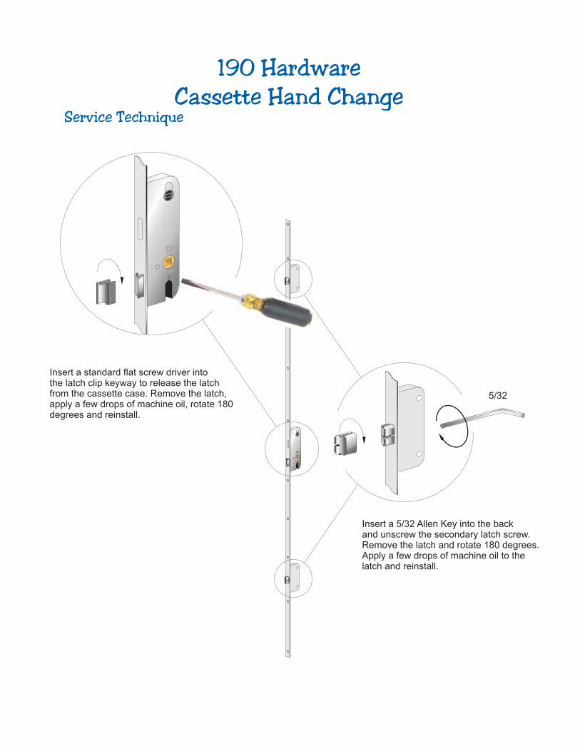
190 HardwareCassette Hand Change
Manufacturer of Alpine Window Products
5/32
Insert a 5/32 Allen Key into the back and unscrew the secondary latch screw. Remove the latch and rotate 180 degrees. Apply a few drops of machine oil to the latch and reinstall.
Insert a standard flat screw driver intothe latch clip keyway to release the latchfrom the cassette case. Remove the latch, apply a few drops of machine oil, rotate 180degrees and reinstall.
Service Technique
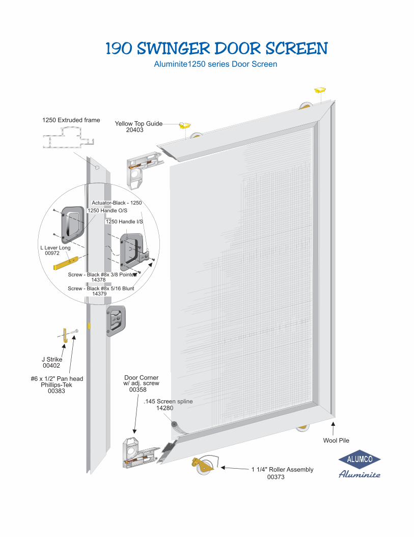
.145 Screen spline14280
1 1/4" Roller Assembly
Yellow Top Guide20403
00373
Door Corner
00358w/ adj. screw
1250 Extruded frame
00402J Strike
#6 x 1/2" Pan head
Screw - Black #8x 3/8 Pointed
Screw - Black #8x 5/16 Blunt
L Lever Long
Actuator-Black - 1250
1250 Handle I/S
Phillips-Tek00383
1250 Handle O/S
00972
14379
14378
Wool Pile
Aluminite1250 series Door Screen
190 SWINGER DOOR SCREEN
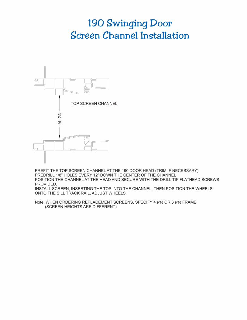
TOP SCREEN CHANNEL
ALIG
N
PREFIT THE TOP SCREEN CHANNEL AT THE 190 DOOR HEAD (TRIM IF NECESSARY)PREDRILL 1/8” HOLES EVERY 12” DOWN THE CENTER OF THE CHANNELPOSITION THE CHANNEL AT THE HEAD AND SECURE WITH THE DRILL TIP FLATHEAD SCREWSPROVIDED.INSTALL SCREEN, INSERTING THE TOP INTO THE CHANNEL, THEN POSITION THE WHEELSONTO THE SILL TRACK RAIL, ADJUST WHEELS.
Note: WHEN ORDERING REPLACEMENT SCREENS, SPECIFY 4 9/16 OR 6 9/16 FRAME (SCREEN HEIGHTS ARE DIFFERENT)
190 Swinging DoorScreen Channel Installation