Embed Size (px)
Citation preview
-C:-'
1900/65A General Purpose Equipment Monitor
Description
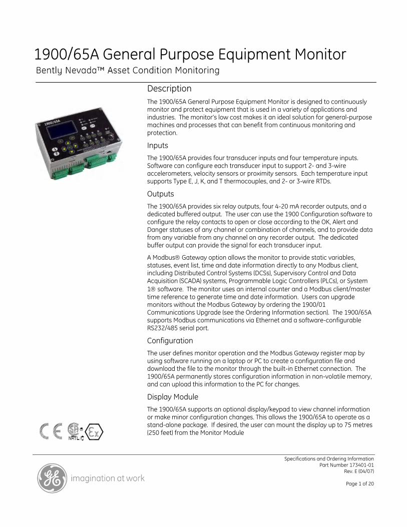
The 1900/65A General Purpose Equipment Monitor is designed to continuously monitor and protect equipment that is used in a variety of applications and industries. The monitor’s low cost makes it an ideal solution for general-purpose machines and processes that can benefit from continuous monitoring and protection.
Inputs The 1900/65A provides four transducer inputs and four temperature inputs. Software can configure each transducer input to support 2- and 3-wire accelerometers, velocity sensors or proximity sensors. Each temperature input supports Type E, J, K, and T thermocouples, and 2- or 3-wire RTDs.
Outputs
The 1900/65A provides six relay outputs, four 4-20 mA recorder outputs, and a dedicated buffered output. The user can use the 1900 Configuration software to configure the relay contacts to open or close according to the OK, Alert and Danger statuses of any channel or combination of channels, and to provide data from any variable from any channel on any recorder output. The dedicated buffer output can provide the signal for each transducer input.
A Modbus Gateway option allows the monitor to provide static variables, statuses, event list, time and date information directly to any Modbus client, including Distributed Control Systems (DCSs), Supervisory Control and Data Acquisition (SCADA) systems, Programmable Logic Controllers (PLCs), or System 1 software. The monitor uses an internal counter and a Modbus client/master time reference to generate time and date information. Users can upgrade monitors without the Modbus Gateway by ordering the 1900/01 Communications Upgrade (see the Ordering Information section). The 1900/65A supports Modbus communications via Ethernet and a software-configurable RS232/485 serial port.
Configuration The user defines monitor operation and the Modbus Gateway register map by using software running on a laptop or PC to create a configuration file and download the file to the monitor through the built-in Ethernet connection. The 1900/65A permanently stores configuration information in non-volatile memory, and can upload this information to the PC for changes.
Display Module The 1900/65A supports an optional display/keypad to view channel information or make minor configuration changes. This allows the 1900/65A to operate as a stand-alone package. If desired, the user can mount the display up to 75 metres (250 feet) from the Monitor Module
Specifications and Ordering Information Part Number 173401-01
Rev. E (04/07)
Page 1 of 20
Feature List • Continuous monitoring and protection is suitable
for auto-shutdown applications
• Stand-alone operation on general-purpose equipment
• Optional Modbus communications via 10BaseT/100BaseTX Ethernet, or software-configurable 485/232 serial port
• Small package. Monitor Module: 196.9 mm x 149.4 mm x 74.4 mm (7.75” x 5.88” x 2.93”). Monitor Module with attached Display Module: 196.9 mm x 149.4 mm x 97.8 mm (7.75” x 5.88” x 3.85)”
• DIN rail or bulkhead mounting options
• 18 to 36 Vdc power input. (optional 110-220 Vac external supply)
• 24-bit ADC conversion
• Four vibration/position/speed inputs
• Four temperature inputs
• Configurable scale factors and full scale ranges
• Up to four processed variables per channel with independent integration and filter control
• Internal OK checking with status
• Independent Alert and Danger setpoints
• 200-entry event list
• Six relay outputs. Relay operation is programmable
• Buffered outputs for each transducer channel
• Four configurable 4-20 mA recorder outputs
• Optional NEMA 4X/IP66 fiberglass housing with window for display
• Painted or stainless steel weatherproof door for panel-mount display
• Hazardous area approvals
• Maritime Approvals
Specifications Inputs
Transducer Inputs
Users can configure Channels 1 through 4 to accept input from acceleration, velocity or displacement transducers.
Transducer Channel Types Channel Types define the functionality for processing that will be applied to an input signal and the kind of variables or measurement values that will be derived from this input. Channel Types also define the kind of sensor that must be used. Transducer Channel Types include:
• Acceleration or Reciprocating Acceleration
• Velocity or Reciprocating Velocity
• Radial Vibration (shaft vibration)
• Thrust (shaft axial displacement)
• Position
• Speed
Acceleration and Reciprocating Acceleration Channel Types
The Acceleration Channel Type and Reciprocating Acceleration Channel Type support two- and three-wire acceleration sensors. The Reciprocating Acceleration channel type has timed OK channel defeat disabled.
Acceleration Variables and Reciprocating Acceleration Variables
Acceleration Variables and Reciprocating Acceleration Variables are filtered and processed measurements from
Specifications and Ordering Information Part Number 173401-01
Rev. E (04/07)
Page 2 of 20
raw transducer signals. The Acceleration Channel Type and Reciprocating Acceleration Channel Type continuously processes up to four variables per channel.
Enveloping High-Pass:
25 Hz to 5 kHz, configurable 4-pole
Enveloping Low-Pass:
Vibration: 125 Hz to 25 kHz, configurable 2-pole Up to three bandpass filtered
amplitude measurements. Enveloped Variable High-Pass:
Acceleration Enveloping:
Users can apply the acceleration enveloping algorithm to one Acceleration or Reciprocating Acceleration Variable.
0.1 Hz min., but greater than Enveloped Variable low-pass 2-pole
Enveloped Variable Low-Pass:
Bias Voltage:
Users may assign the value of the transducer bias voltage to any of the variables. Greater than Enveloped Variable
high-pass and less than Enveloping high-pass 4-pole Configuration
Options Bias Filter:
Each variable is independently configured with the following options.
0.01 Hz 1-pole low-pass
OK Filter:
2.4 kHz 1-pole low-pass Vibration Variables: Full Scale Range
Peak or RMS Vibration:
Metric or English units 20 to 500 m/s2 (2 to 50 g) peak and RMS Filter corner frequencies
Full scale range Enveloped:
Acceleration integrated to velocity
20 to 500 m/s2 (2 to 50 g) peak and RMS
Enveloped Variable:
Integrated: Filter corner frequencies 10 to 100 mm/s (0.4 to 4 in/s)
peak and RMS Standard or Enhanced demodulation
Bias Voltage: Filters -24 V
Vibration Variable:
Accuracy
Vibration Variables:
0.5 Hz – 25 kHz configurable 4-pole high-pass, 4-pole low-pass
±1% of full scale range
Specifications and Ordering Information Part Number 173401-01
Rev. E (04/07)
Page 3 of 20
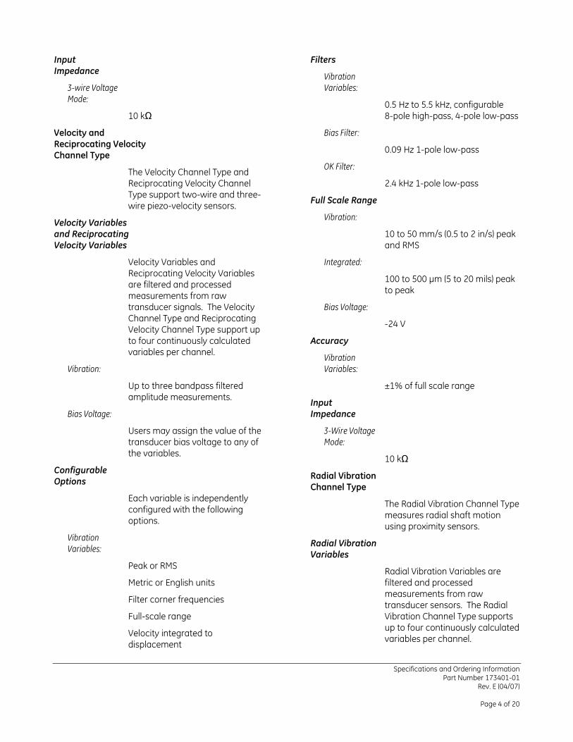
Filters Input Impedance
Vibration Variables: 3-wire Voltage
Mode: 0.5 Hz to 5.5 kHz, configurable 8-pole high-pass, 4-pole low-pass 10 kΩ
Velocity and Reciprocating Velocity Channel Type
Bias Filter:
0.09 Hz 1-pole low-pass
OK Filter: The Velocity Channel Type and Reciprocating Velocity Channel Type support two-wire and three-wire piezo-velocity sensors.
2.4 kHz 1-pole low-pass
Full Scale Range
Vibration: Velocity Variables and Reciprocating Velocity Variables
10 to 50 mm/s (0.5 to 2 in/s) peak and RMS
Velocity Variables and Reciprocating Velocity Variables are filtered and processed measurements from raw transducer signals. The Velocity Channel Type and Reciprocating Velocity Channel Type support up to four continuously calculated variables per channel.
Integrated:
100 to 500 µm (5 to 20 mils) peak to peak
Bias Voltage:
-24 V
Accuracy
Vibration Variables: Vibration:
±1% of full scale range Up to three bandpass filtered amplitude measurements. Input
Impedance Bias Voltage:
Users may assign the value of the transducer bias voltage to any of the variables.
3-Wire Voltage Mode:
10 kΩ Configurable Options Radial Vibration
Channel Type Each variable is independently configured with the following options.
The Radial Vibration Channel Type measures radial shaft motion using proximity sensors.
Vibration Variables:
Radial Vibration Variables
Peak or RMS Radial Vibration Variables are filtered and processed measurements from raw transducer sensors. The Radial Vibration Channel Type supports up to four continuously calculated variables per channel.
Metric or English units
Filter corner frequencies
Full-scale range
Velocity integrated to displacement
Specifications and Ordering Information
Part Number 173401-01 Rev. E (04/07)
Page 4 of 20

Full Scale Range Direct:
Up to three bandpass filtered amplitude measurements
Direct:
100 to 500 µm (3 to 20 mils) peak-to-peak Gap:
Gap voltage Gap:
-24 V Vibration:
Up to three bandpass filtered amplitude measurements
Accuracy
Vibration Variables: Configurable
Options ±1% of full-scale range Each variable is independently configured with the following options.
Input Impedance
Non-configurable:
Vibration Variables:
10 kΩ Metric or English units Thrust Channel Type Filter corner frequencies
Number of filter poles The Thrust Channel Type measures axial shaft motion using proximity sensors.
Full-cale range
Filters Thrust Variables
Direct Filter 1: Thrust Variables are filtered and processed measurements from raw transducer signals.
4 to 4000 Hz (240 to 240,000 RPM)
Direct Filter 2:
1 to 600 Hz (60 to 36,000 RPM) Position:
Axial position of shaft Direct Filter Characteristics:
Gap: High-pass set by attack and decay, 1-pole low-pass Gap, voltage or position
Configurable Options Gap Filter:
0.09 Hz 1-pole low-pass Each variable is independently configured with the following options.
Vibration Variables:
0.5 Hz to 4 kHz, configurable Position Variables: 1-, 2-, or 4-pole high-pass and
low-pass, configurable Metric or English units
Full-scale range OK Filter:
2.4 kHz 1-pole low-pass Filters
Direct Filter:
1.2 Hz 1-pole low-pass
Specifications and Ordering Information Part Number 173401-01
Rev. E (04/07)
Page 5 of 20
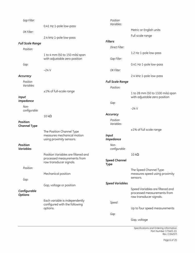
Position Variables:
Gap Filter:
0.41 Hz 1-pole low-pass Metric or English units
OK Filter: Full scale range 2.4 kHz 1-pole low-pass
Filters Full Scale Range Direct Filter:
Position: 1.2 Hz 1-pole low-pass 1 to 4 mm (50 to 150 mils) span
with adjustable zero position Gap Filter:
0.41 Hz 1-pole low-pass Gap:
–24 V OK Filter:
2.4 kHz 1-pole low-pass Accuracy
Full Scale Range Position Variables:
Position: ±1% of full-scale range 1 to 28 mm (50 to 1100 mils) span
with adjustable zero position Input Impedance
Gap: Non-configurable:
-24 V
Accuracy 10 kΩ Position Variables:
Position Channel Type
±1% of full scale range The Position Channel Type measures mechanical motion using proximity sensors.
Input Impedance
Position Variables
Non-configurable:
10 kΩ Position Variables are filtered and processed measurements from raw transducer signals. Speed Channel
Type Position: The Speed Channel Type
measures speed using proximity sensors.
Mechanical position
Gap: Speed Variables Gap, voltage or position
Speed Variables are filtered and processed measurements from raw transducer signals.
Configurable Options
Each variable is independently configured with the following options.
Speed:
Up to four speed measurements
Gap:
Gap, voltage
Specifications and Ordering Information Part Number 173401-01
Rev. E (04/07)
Page 6 of 20
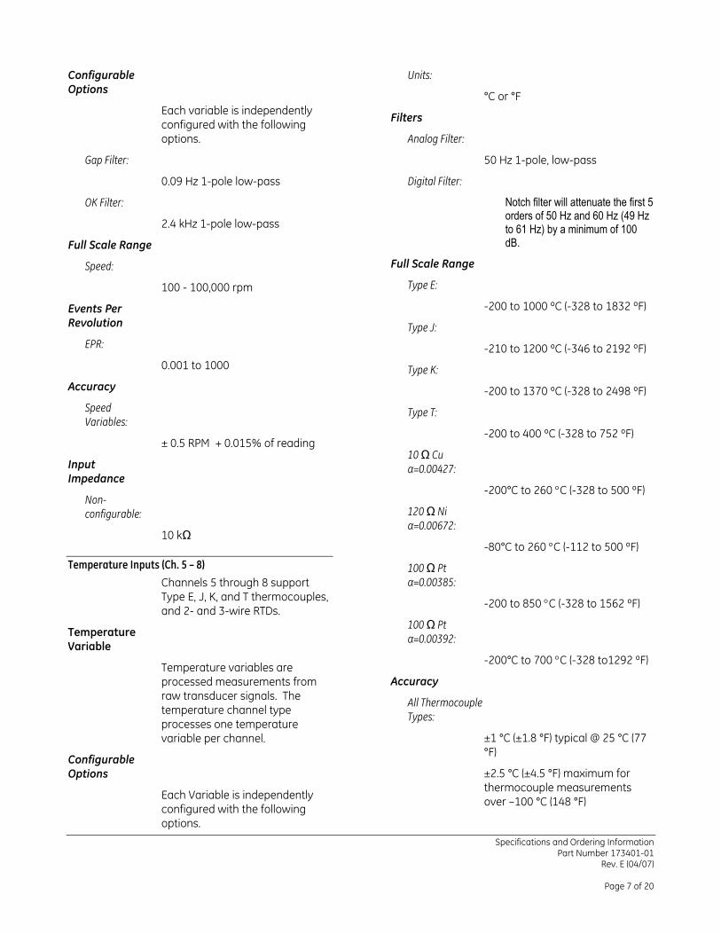
Configurable Options
Units:
°C or °F Each variable is independently configured with the following options.
Filters
Analog Filter:
50 Hz 1-pole, low-pass Gap Filter:
0.09 Hz 1-pole low-pass Digital Filter:
Notch filter will attenuate the first 5 orders of 50 Hz and 60 Hz (49 Hz to 61 Hz) by a minimum of 100 dB.
OK Filter:
2.4 kHz 1-pole low-pass
Full Scale Range
Full Scale Range Speed:
Type E: 100 - 100,000 rpm
-200 to 1000 ºC (-328 to 1832 ºF) Events Per Revolution Type J:
EPR: -210 to 1200 ºC (-346 to 2192 ºF) 0.001 to 1000 Type K:
Accuracy -200 to 1370 ºC (-328 to 2498 ºF) Speed Variables:
Type T:
-200 to 400 ºC (-328 to 752 ºF) ± 0.5 RPM + 0.015% of reading
10 Ω Cu α=0.00427: Input
Impedance -200°C to 260 °C (-328 to 500 ºF)
Non-configurable: 120 Ω Ni
α=0.00672: 10 kΩ
-80°C to 260 °C (-112 to 500 ºF) Temperature Inputs (Ch. 5 – 8) 100 Ω Pt
α=0.00385: Channels 5 through 8 support Type E, J, K, and T thermocouples, and 2- and 3-wire RTDs.
-200 to 850 °C (-328 to 1562 ºF)
100 Ω Pt α=0.00392: Temperature
Variable -200°C to 700 °C (-328 to1292 ºF)
Temperature variables are processed measurements from raw transducer signals. The temperature channel type processes one temperature variable per channel.
Accuracy
All Thermocouple Types:
±1 °C (±1.8 °F) typical @ 25 °C (77 °F)
Configurable Options ±2.5 °C (±4.5 °F) maximum for
thermocouple measurements over –100 °C (148 °F) Each Variable is independently
configured with the following options.
Specifications and Ordering Information Part Number 173401-01
Rev. E (04/07)
Page 7 of 20
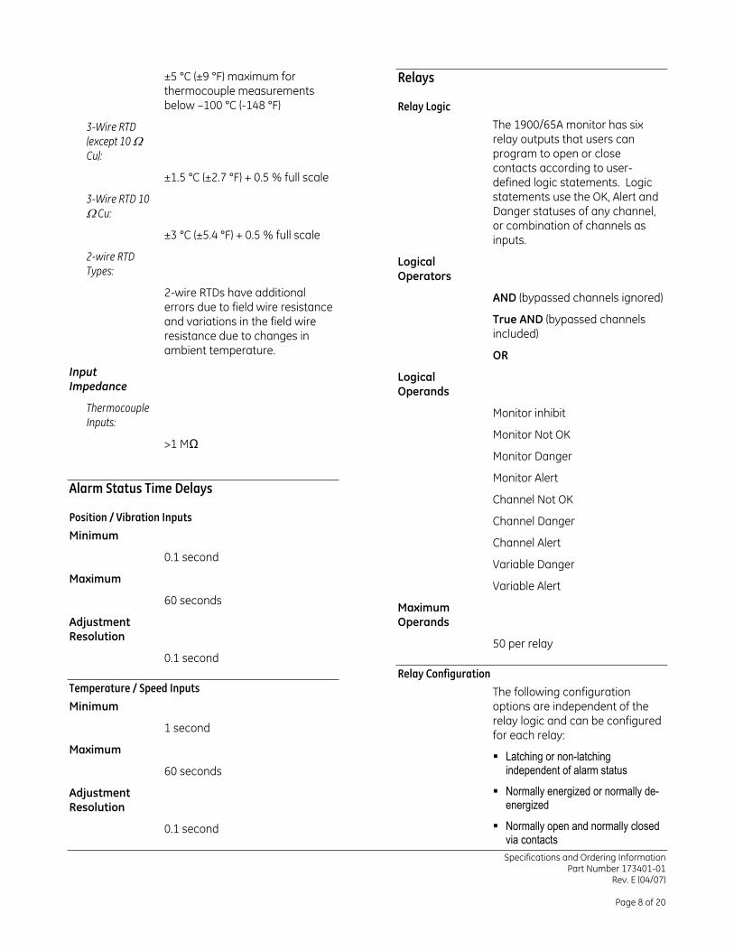
Relays ±5 °C (±9 °F) maximum for thermocouple measurements below –100 °C (-148 °F) Relay Logic
The 1900/65A monitor has six relay outputs that users can program to open or close contacts according to user-defined logic statements. Logic statements use the OK, Alert and Danger statuses of any channel, or combination of channels as inputs.
3-Wire RTD (except 10 Ω Cu):
±1.5 °C (±2.7 °F) + 0.5 % full scale
3-Wire RTD 10 Ω Cu:
±3 °C (±5.4 °F) + 0.5 % full scale
2-wire RTD Types:
Logical Operators
2-wire RTDs have additional errors due to field wire resistance and variations in the field wire resistance due to changes in ambient temperature.
AND (bypassed channels ignored)
True AND (bypassed channels included)
OR Input Impedance
Logical Operands
Thermocouple Inputs:
Monitor inhibit
Monitor Not OK >1 MΩ
Monitor Danger
Monitor Alert Alarm Status Time Delays
Channel Not OK Position / Vibration Inputs Channel Danger Minimum Channel Alert
0.1 second Variable Danger Maximum Variable Alert
60 seconds Maximum Operands Adjustment
Resolution 50 per relay 0.1 second
Relay Configuration Temperature / Speed Inputs The following configuration
options are independent of the relay logic and can be configured for each relay:
Minimum
1 second
Maximum Latching or non-latching
independent of alarm status 60 seconds
Normally energized or normally de-energized
Adjustment Resolution
Normally open and normally closed via contacts
0.1 second
Specifications and Ordering Information Part Number 173401-01
Rev. E (04/07)
Page 8 of 20
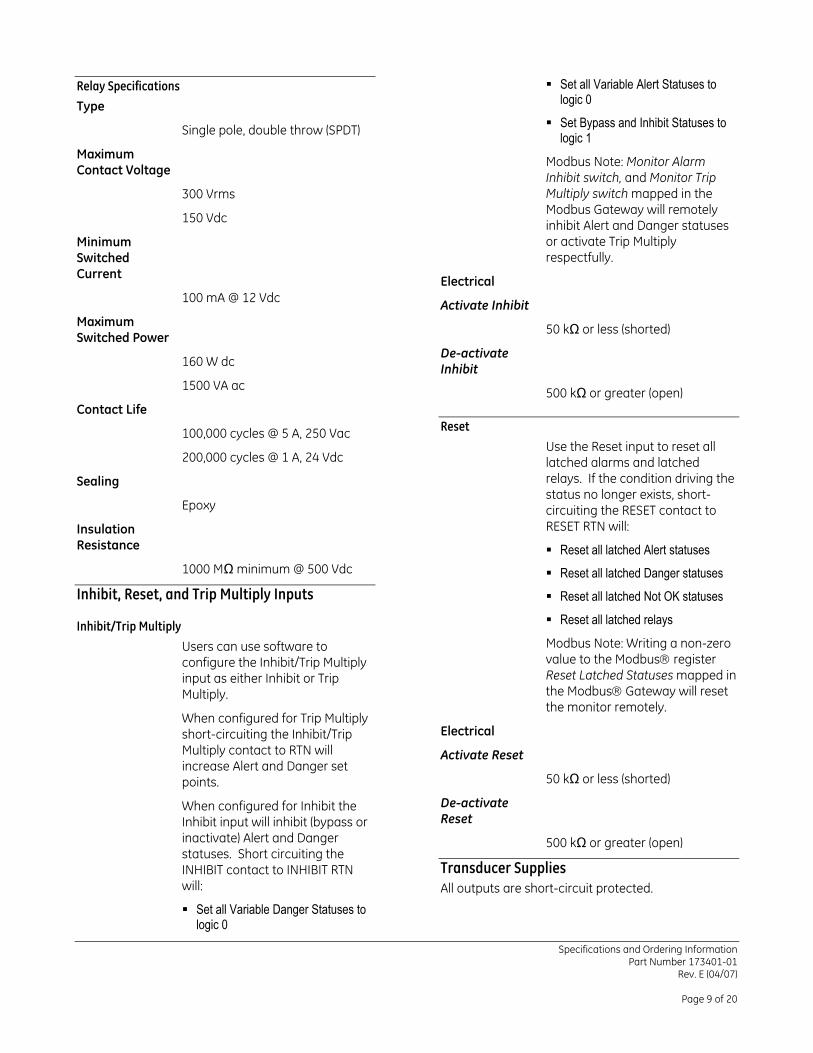
Set all Variable Alert Statuses to logic 0
Relay Specifications
Type Set Bypass and Inhibit Statuses to
logic 1 Single pole, double throw (SPDT)
Maximum Contact Voltage
Modbus Note: Monitor Alarm Inhibit switch, and Monitor Trip Multiply switch mapped in the Modbus Gateway will remotely inhibit Alert and Danger statuses or activate Trip Multiply respectfully.
300 Vrms
150 Vdc
Minimum Switched Current Electrical
100 mA @ 12 Vdc Activate Inhibit Maximum Switched Power
50 kΩ or less (shorted)
De-activate Inhibit 160 W dc
1500 VA ac 500 kΩ or greater (open) Contact Life
Reset 100,000 cycles @ 5 A, 250 Vac Use the Reset input to reset all latched alarms and latched relays. If the condition driving the status no longer exists, short-circuiting the RESET contact to RESET RTN will:
200,000 cycles @ 1 A, 24 Vdc
Sealing
Epoxy
Insulation Resistance Reset all latched Alert statuses
1000 MΩ minimum @ 500 Vdc Reset all latched Danger statuses Inhibit, Reset, and Trip Multiply Inputs Reset all latched Not OK statuses
Reset all latched relays Inhibit/Trip Multiply Modbus Note: Writing a non-zero value to the Modbus register Reset Latched Statuses mapped in the Modbus Gateway will reset the monitor remotely.
Users can use software to configure the Inhibit/Trip Multiply input as either Inhibit or Trip Multiply.
When configured for Trip Multiply short-circuiting the Inhibit/Trip Multiply contact to RTN will increase Alert and Danger set points.
Electrical
Activate Reset
50 kΩ or less (shorted)
De-activate Reset
When configured for Inhibit the Inhibit input will inhibit (bypass or inactivate) Alert and Danger statuses. Short circuiting the INHIBIT contact to INHIBIT RTN will:
500 kΩ or greater (open)
Transducer Supplies All outputs are short-circuit protected.
Set all Variable Danger Statuses to logic 0
Specifications and Ordering Information Part Number 173401-01
Rev. E (04/07)
Page 9 of 20
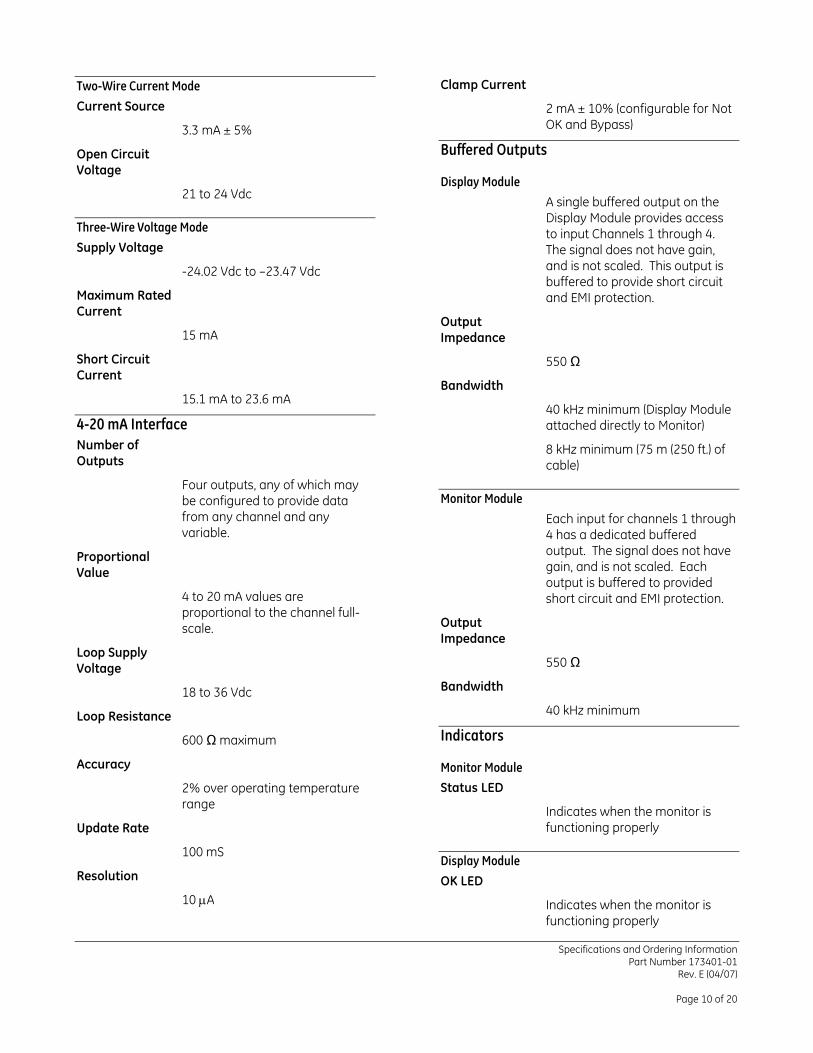
Clamp Current Two-Wire Current Mode
Current Source 2 mA ± 10% (configurable for Not OK and Bypass) 3.3 mA ± 5%
Buffered Outputs Open Circuit Voltage
Display Module 21 to 24 Vdc A single buffered output on the
Display Module provides access to input Channels 1 through 4. The signal does not have gain, and is not scaled. This output is buffered to provide short circuit and EMI protection.
Three-Wire Voltage Mode
Supply Voltage
-24.02 Vdc to –23.47 Vdc
Maximum Rated Current
Output Impedance 15 mA
Short Circuit Current
550 Ω
Bandwidth 15.1 mA to 23.6 mA
40 kHz minimum (Display Module attached directly to Monitor) 4-20 mA Interface
Number of Outputs
8 kHz minimum (75 m (250 ft.) of cable)
Four outputs, any of which may be configured to provide data from any channel and any variable.
Monitor Module
Each input for channels 1 through 4 has a dedicated buffered output. The signal does not have gain, and is not scaled. Each output is buffered to provided short circuit and EMI protection.
Proportional Value
4 to 20 mA values are proportional to the channel full-scale. Output
Impedance Loop Supply Voltage 550 Ω
Bandwidth 18 to 36 Vdc 40 kHz minimum Loop Resistance
Indicators 600 Ω maximum
Accuracy Monitor Module Status LED 2% over operating temperature
range Indicates when the monitor is functioning properly Update Rate
100 mS Display Module
Resolution OK LED 10 µA Indicates when the monitor is
functioning properly
Specifications and Ordering Information Part Number 173401-01
Rev. E (04/07)
Page 10 of 20
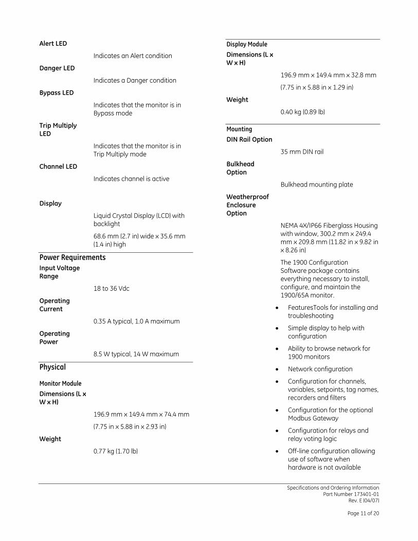
Alert LED Display Module
Dimensions (L x W x H)
Indicates an Alert condition
Danger LED 196.9 mm x 149.4 mm x 32.8 mm
Indicates a Danger condition (7.75 in x 5.88 in x 1.29 in)
Bypass LED Weight
Indicates that the monitor is in Bypass mode 0.40 kg (0.89 lb)
Trip Multiply LED
Mounting
DIN Rail Option Indicates that the monitor is in Trip Multiply mode 35 mm DIN rail
Bulkhead Option
Channel LED
Indicates channel is active Bulkhead mounting plate
Weatherproof Enclosure Option
Display
Liquid Crystal Display (LCD) with backlight NEMA 4X/IP66 Fiberglass Housing
with window, 300.2 mm x 249.4 mm x 209.8 mm (11.82 in x 9.82 in x 8.26 in)
68.6 mm (2.7 in) wide x 35.6 mm (1.4 in) high
Power Requirements The 1900 Configuration Software package contains everything necessary to install, configure, and maintain the 1900/65A monitor.
Input Voltage Range
18 to 36 Vdc
Operating Current • FeaturesTools for installing and
troubleshooting 0.35 A typical, 1.0 A maximum
• Simple display to help with configuration Operating
Power • Ability to browse network for
1900 monitors 8.5 W typical, 14 W maximum
Physical • Network configuration
• Configuration for channels, variables, setpoints, tag names, recorders and filters
Monitor Module
Dimensions (L x W x H)
• Configuration for the optional Modbus Gateway 196.9 mm x 149.4 mm x 74.4 mm
(7.75 in x 5.88 in x 2.93 in) • Configuration for relays and relay voting logic Weight
• Off-line configuration allowing use of software when hardware is not available
0.77 kg (1.70 lb)
Specifications and Ordering Information Part Number 173401-01
Rev. E (04/07)
Page 11 of 20
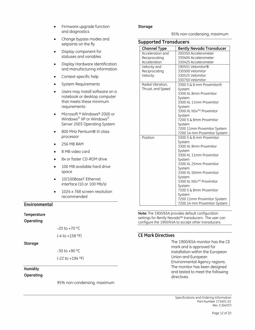
• Firmware upgrade function and diagnostics
Storage
95% non-condensing, maximum • Change bypass modes and
setpoints on the fly Supported Transducers Channel Type Bently Nevada Transducer Acceleration and Reciprocating Acceleration
200350 Accelerometer 330400 Accelerometer 330425 Accelerometer
Velocity and Reciprocating Velocity
190501 Velomitor® 330500 Velomitor 330525 Velomitor 330750 Velomitor
Radial Vibration, Thrust, and Speed
3300 5 & 8 mm Proximitor System 3300 XL 8mm Proximitor System 3300 XL 11mm Proximitor System 3300 XL NSvTM Proximitor System 7200 5 & 8mm Proximitor System 7200 11mm Proximitor System 7200 14 mm Proximitor System
Position 3300 5 & 8 mm Proximitor System 3300 XL 8mm Proximitor System 3300 XL 11mm Proximitor System 3300 XL 25mm Proximitor System 3300 XL 50mm Proximitor System 3300 XL NSvTM Proximitor System 7200 5 & 8mm Proximitor System 7200 11mm Proximitor System 7200 14 mm Proximitor System
• Display component for statuses and variables
• Display Hardware Identification and manufacturing information
• Context-specific help
• System Requirements
• Users may install software on a notebook or desktop computer that meets these minimum requirements:
• Microsoft ® Windows® 2000 or Windows XP or Windows Server 2003 Operating System
• 800 MHz Pentium® III class processor
• 256 MB RAM
• 8 MB video card
• 8x or faster CD-ROM drive
• 100 MB available hard drive space
• 10/100BaseT Ethernet interface (10 or 100 Mb/s)
• 1024 x 768 screen resolution recommended
Environmental Note: The 1900/65A provides default configuration settings for Bently Nevada™ transducers. The user can configure the 1900/65A to accept other transducers.
Temperature
Operating
-20 to +70 ºC
CE Mark Directives (-4 to +158 ºF) The 1900/65A monitor has the CE mark and is approved for installation within the European Union and European Environmental Agency regions. The monitor has been designed and tested to meet the following directives.
Storage
-30 to +90 ºC
(-22 to +194 ºF)
Humidity
Operating
95% non-condensing, maximum
Specifications and Ordering Information Part Number 173401-01
Rev. E (04/07)
Page 12 of 20
EMC Standards EMC Directives
This product is tested to meet Council Directive 89/336/EEC Electromagnetic Compatibility (EMC) and the listed standards, in whole or in part, documented in a technical construction file. EN61000-6-4 Generic emission standard, Part 2, Industrial Environment. EN61000-6-2 EMC Generic Immunity standard, Part 2, Industrial Environment.
EN61000-604
Radiated Emissions
EN 55011, Class A
Conducted Emissions
EN 55011, Class A
EN61000-6-2
Electrostatic Discharge
Hazardous Area Approvals EN 61000-4-2, Criteria B This monitor is not certified for installation in Class 1 Div 1 locations, but it will support transducers installed in Div 1 locations via the use of galvanic isolators and barriers. If galvanic isolators are used, no change is necessary to the installation. A removable ground jumper allows the monitor to support zener barrier installations. Removing the jumper will disconnect circuit common from chassis at the monitor so that chassis can be connected at the barrier.
Radiated Susceptibility
EN61000-4-3, Criteria A
Electrical Fast Transient
EN 61000-4-4, Criteria B
Surge Capability
EN 61000-4-5, Criteria B
Conducted Susceptibility
EN61000-4-6, Criteria A North American Low Frequency Conducted Susceptibility
Ex/AEx nA [L] IIC
Class I Division 2 Groups A B C D
T4 @ -20 °C ≤ Ta ≤ 70 ºC IEC 60945, Criteria A
Vn = 18 to 36 Vdc @ Imax = 1A per drawing 173089
Low Voltage Directives
The 1900/65A Monitor meets Council Directive 73/23/EEC Low Voltage when the 24 Vdc power source is approved to the Low Voltage Directive. Our power supply P/N 02200794 meets this requirement.
European
II 3G Ex nA [nL] IIC T4
@-20 °C ≤ Ta ≤ 70 °C
Sira 06 ATEX 4053X
IECEx SIR 06.0012X per drawing 173089 EN 61010-1
Safety Requirements
Maritime
DNV Cert A-9974 Safety Requirements for Measurement, Control, and Laboratory Use
Specifications and Ordering Information Part Number 173401-01
Rev. E (04/07)
Page 13 of 20
Ordering Information
1900/65A General Purpose Equipment Monitor 1900/65A-AXX-BXX-CXX-DXX-EXX
A: Power Option 0 0 18 to 36 Vdc 0 1 110 to 220 Vac @ 50 to 60 Hz
(external supply) B: Display Option
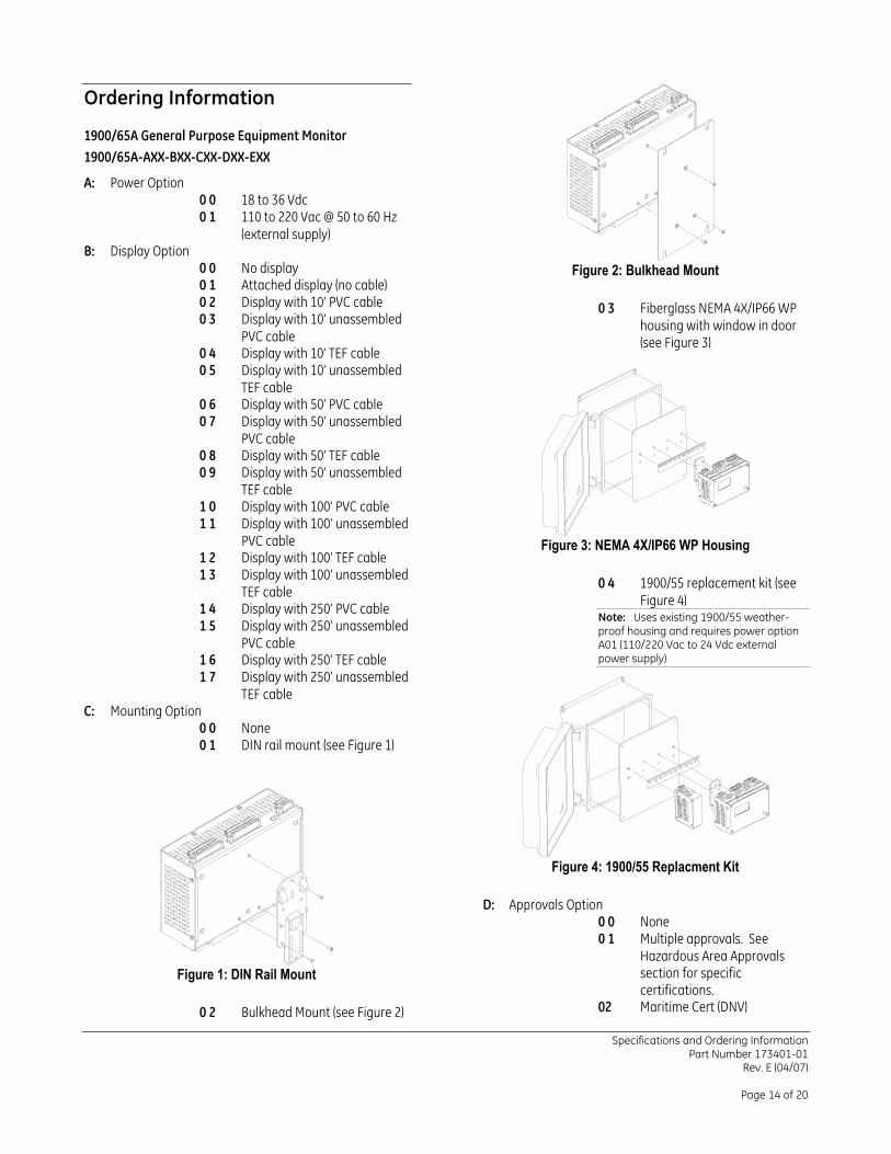
0 0 No display Figure 2: Bulkhead Mount 0 1 Attached display (no cable) 0 2 Display with 10’ PVC cable 0 3 Fiberglass NEMA 4X/IP66 WP
housing with window in door (see Figure 3)
0 3 Display with 10’ unassembled PVC cable
0 4 Display with 10’ TEF cable 0 5 Display with 10’ unassembled
TEF cable
0 6 Display with 50’ PVC cable 0 7 Display with 50’ unassembled
PVC cable 0 8 Display with 50’ TEF cable 0 9 Display with 50’ unassembled
TEF cable 1 0 Display with 100’ PVC cable 1 1 Display with 100’ unassembled
PVC cable Figure 3: NEMA 4X/IP66 WP Housing 1 2 Display with 100’ TEF cable
1 3 Display with 100’ unassembled TEF cable
0 4 1900/55 replacement kit (see Figure 4) 1 4 Display with 250’ PVC cable
Note: Uses existing 1900/55 weather-proof housing and requires power option A01 (110/220 Vac to 24 Vdc external power supply)
1 5 Display with 250’ unassembled PVC cable
1 6 Display with 250’ TEF cable 1 7 Display with 250’ unassembled
TEF cable
C: Mounting Option 0 0 None 0 1 DIN rail mount (see Figure 1)
Figure 4: 1900/55 Replacment Kit
D: Approvals Option 0 0 None 0 1 Multiple approvals. See
Hazardous Area Approvals section for specific certifications.
Figure 1: DIN Rail Mount
02 Maritime Cert (DNV) 0 2 Bulkhead Mount (see Figure 2)
Specifications and Ordering Information Part Number 173401-01
Rev. E (04/07)
Page 14 of 20
E: Communications Option 168547-0010-01-02 0 0 None
3 m (10 ft) PVC cable, unassembled
0 1 Modbus communications
1900/01 – 1900/65A General Communications Monitor, Communications Upgrade
168547-0010-02-01
3 m (10 ft) TEF cable, assembled 1900/01-AXX-BXX-CXX-DXX
168547-0010-02-02 A: Order Type Option
3 m (10 ft) TEF cable, unassembled
0 1 New order (CD, key, and binder)
9 8 Replacement licenses (key) 168547-0050-01-01 9 9 Update (CD)
15 m (50 ft) PVC cable, assembled B: Communications Option 0 1 Modbus communications 168547-0050-01-02 C: License Key Type Option 0 0 None 15 m (50 ft) PVC cable,
unassembled 0 1 USB license key 0 2 Floppy disk license key
168547-0050-02-01 D: License Quantity Option X X Total licenses (1 to 99) 15 m (50 ft) TEF cable, assembled
Accessories 168547-0050-02-02
15 m (50 ft) TEF cable, unassembled
167699-02
1900/65A Display Module 168547-0100-01-01
173400-01 30 m (100 ft) PVC cable, assembled 1900/65A Product Manual
172250-01 168547-0100-01-02
1900/65 Modbus Gateway Users Guide
30 m (100 ft) PVC cable, unassembled
173089-01 168547-0100-02-01
1900/65A Field Wiring Diagrams 30 m (100 ft) TEF cable, assembled 02200794
168547-0100-02-02
Power supply, 110/220 Vac to 24 Vdc 2.5 A DIN rail mount
30 m (100 ft) TEF cable, unassembled
02200121
DIN rail end bracket 168547-0250-01-01 168374
35mm DIN rail mounting clip for 1900/65A Monitor Module
75 m (250 ft) PVC cable, assembled
168495 168547-0250-01-02 Bulkhead mounting plate
75 m (250 ft) PVC cable, unassembled
168547-0010-01-01
3 m (10 ft) PVC cable, assembled
Specifications and Ordering Information
Part Number 173401-01 Rev. E (04/07)
Page 15 of 20
168944 168547-0250-02-01 Fiberglass NEMA 4X/IP66
weatherproof housing with window in door
75 m (250 ft) TEF cable, assembled
02295055 168547-0250-02-02 MTL 728(-) barrier
75 m (250 ft) TEF cable, unassembled 02245002
MTL 796(-) barrier 168628 172555 Stainless steel NEMA 4X
weatherproof door for panel-mount display assembly
Modbus/TCP (Ethernet) to Modbus/RTU (Serial) Converter
169825-01 168629
Training CD Painted steel NEMA 4 weatherproof door for panel-mount display assembly
Specifications and Ordering Information Part Number 173401-01
Rev. E (04/07)
Page 16 of 20
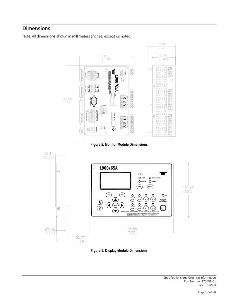
Dimensions Note: All dimensions shown in millimeters (inches) except as noted.
Figure 5: Monitor Module Dimensions
Figure 6: Display Module Dimensions
Specifications and Ordering Information Part Number 173401-01
Rev. E (04/07)
Page 17 of 20
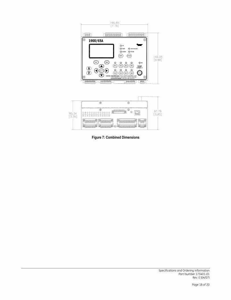
Figure 7: Combined Dimensions
Specifications and Ordering Information Part Number 173401-01
Rev. E (04/07)
Page 18 of 20
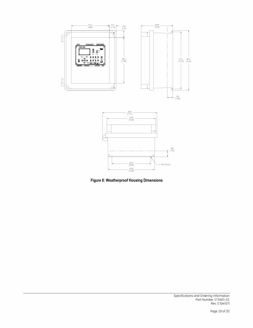
Figure 8: Weatherproof Housing Dimensions
Specifications and Ordering Information Part Number 173401-01
Rev. E (04/07)
Page 19 of 20
Specifications and Ordering Information Part Number 173401-01
Rev. E (04/07)
Page 20 of 20
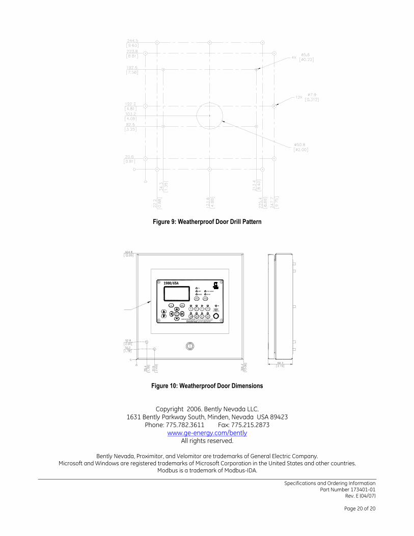
Figure 9: Weatherproof Door Drill Pattern
Figure 10: Weatherproof Door Dimensions
Copyright 2006. Bently Nevada LLC. 1631 Bently Parkway South, Minden, Nevada USA 89423
Phone: 775.782.3611 Fax: 775.215.2873 www.ge-energy.com/bently
All rights reserved.
Bently Nevada, Proximitor, and Velomitor are trademarks of General Electric Company. Microsoft and Windows are registered trademarks of Microsoft Corporation in the United States and other countries.
Modbus is a trademark of Modbus-IDA.