Embed Size (px)
Citation preview

MAF-10100 FORD MUSTANG 1965-1970 MAGNUM Installation, Rev A 05/08/17
1965 – 1970 FORD MUSTANG
T56 MAGNUM 6-SPEED INSTALLATION MANUAL
FOLLOW FACTORY SERVICE MANUAL (FSM) RECOMMENDED SAFETY PRECAUTIONS. TRANSMISSION REMOVAL AND INSTALLATION IS A LABOR INTENSIVE JOB, WHICH CAN RESULT IN SERIOUS INJURY OR DEATH IF CAUTION IS NOT TAKEN. PLEASE BE CAREFUL PERFORMING THIS JOB, OR HAVE A PROFESSIONAL PERFORM THE JOB FOR YOU. REFER TO FSM FOR ADDITIONAL DETAILS OF THE PROCEDURES BELOW, AS REQUIRED.
The material herein is the intellectual property of Silver Sport Transmissions (“SST”) and is to be used by SST customers or their authorized installers for the sole purpose of installing SST-supplied transmissions and related parts. Under no circumstances shall the manual or any portion thereof be copied, duplicated, distributed or incorporated in any written or printed document without the
express written approval of Silver Sport Transmissions.
2 MAF-10100 FORD MUSTANG 1965-1970 MAGNUM Installation, Rev A 05/08/17
Before you start:
Test drive the vehicle, if possible, before you begin. Pay attention to noise and vibration and record your observations. At the end of the installation, perform another test drive to compare results. It is also a good idea to measure engine driveline angle and driveshaft operating angles for your existing transmission to use as a comparison to the new angles after the T56 Magnum is installed. You should also verify the parts you received. Compare the received items to the detailed invoice provided in your shipment.
PLEASE READ ALL INSTRUCTIONS BEFORE INSTALLATION
In addition to these instructions, you should receive the following instructions based on your order, if applicable:
1. All kits – MAA-00101 Inspection and Correction of Bellhousing to Crankshaft Runout 2. MAM-00201 Hydraulic Kit Instructions for FORD 3. MAA-00801 T56 Magnum Installation General Guidelines
A. REMOVE EXISTING EQUIPMENT 1. Disconnect negative (-) battery cable. 2. Remove breather assembly and fan shroud. 3. Remove distributor cap if the engine is a small block. 4. Place shifter in neutral. Remove shift boot and lever. 5. Remove console, if equipped. 6. Raise car securely on lift or jack stands. 18 inches or more of working room is
recommended. 7. Remove exhaust, as required, for working clearance. 8. Unbolt starter and set aside. 9. Remove clutch linkage at torque arm to clutch fork. 10. Remove bellhousing dust cover.
NOTE: Transmission must be test shifted before installation. Due to jostling during shipping, some transmissions will not shift properly when removed from the box. Please
make sure that the gear selector will move into each of the shift gate positions while rotating the input shaft and checking for output shaft rotation. If the input shaft will not turn, slide a
clutch disc over the input shaft and jerk the clutch disc left and right to break it free. If this does not correct the issue, call Silver Sport Transmissions at 888-609-0094 for help.
THIS CANNOT BE CORRECTED WITH THE TRANSMISSION INSTALLED IN THE CAR! TEST SHIFT FIRST!
3 MAF-10100 FORD MUSTANG 1965-1970 MAGNUM Installation, Rev A 05/08/17
11. Disconnect driveshaft from differential and remove from car. 12. Remove shifter assembly. 13. Remove speedometer cable. 14. Disconnect reverse lamp wiring. 15. Secure rear of engine with a hydraulic jack. 16. Unbolt transmission isolator from the crossmember and remove crossmember. 17. Secure transmission (jack recommended) and unbolt from bellhousing, then move
rearward and remove from vehicle. 18. Remove bellhousing and clutch unit. 19. Inspect flywheel ring gear teeth (no cracks, chips, wear), and friction surface (no
cracks). Silver Sport Transmissions strongly suggests removing flywheel and having it resurfaced, then dynamically balanced at a reputable automotive machine shop unless the engine was externally balanced with the flywheel installed.
20. Remove manual transmission pilot bushing. B. TUNNEL MODIFICATION
Because the T56 Magnum transmission is longer than factory original manual or automatic transmission, some tunnel modification will be required to install the T56 Magnum transmission to the proper driveline angle to obtain acceptable driveshaft operating angles. Your SST Mustang T56 Magnum kit includes special adjustable motor mounts and the “Uni-Cross” universal fit crossmember from Ron Morris Performance (RMP). These components will allow installation of the T56 Magnum with minimal modification to the tunnel floor area. Refer to the RMP instructions included with these components.
1. Remove the front seats and carpet.
2. Temporarily attach bell housing (without clutch components) to the engine.
3. From rear face of bell housing (transmission mounting face), measure 21.125” on driveline centerline and mark tower center location on underside of tunnel. Drill 1/8” dia shifter locating hole thru tunnel.
4. Cut out the paper tunnel cutting template TMG-10205. Place the paper template on the top of tunnel to align with the 1/8” dia shifter locating hole and tape to tunnel.
5. Mark the area to be cut for the desired lower body boot by tracing around the
template cross hatched area.
6. Carefully cut the opening area.
4 MAF-10100 FORD MUSTANG 1965-1970 MAGNUM Installation, Rev A 05/08/17
C. TEST FITMENT
1. Once your floor support crossmember has been modified and the new crossmember modified per the RPM instructions, a trial fit for T56 Magnum tunnel clearance should be done.
2. Lower engine and install transmission to bellhousing using bolts from hardware pack HWM-PACK AT56. Support the transmission with a jack.
3. Attach isolator mount to transmission using Hardware Pack HWF-Pack C.
4. Raise the transmission enough to be able to install the new crossmember under
the isolator mount. For added clearance for shifter stub to clear tunnel hole when transmission is being installed, place transmission into 5th or REV gear.
NOTE: DO NOT REMOVE SHIFTER TOWER FROM SHIFTER BASE PLATE to gain clearance for installation. Shift stub seal in shifter base plate could be damaged or not properly fitted on lower stub lever if tower is reinstalled on shifter base plate.
5. Verify 1/8 to 1/4” minimum clearance between T56 Magnum and tunnel. An
easy way to check areas that you cannot see is to use a length of rubber hose that is 1/4” outside diameter. Loop it over the transmission at the bellhousing and see if you can slide it all the way to the tail housing. If the transmission has less than 1/4” clearance at any point in the tunnel, you may be able to “massage” the tunnel with a hammer and dolly to prevent cutting the tunnel.
6. This would be a good time to take the driveline measurement per the driveline
instruction sheet so that the new SST driveshaft can be ordered. See MAA-00100 form in the customer info pack.
7. Once proper tunnel to Magnum transmission clearance has been verified, remove crossmember, transmission, and the bell housing to gain underside access to complete final tunnel sheet metal modification by painting exposed sheet metal surfaces for corrosion protection.
5 MAF-10100 FORD MUSTANG 1965-1970 MAGNUM Installation, Rev A 05/08/17
D. INSTALL NEW EQUIPMENT
1) Clean all mating engine surfaces and dowel pins. Verify dowel pin full diameter exposed length is greater than 3/8” to assure that Quick Time bell housing will be accurately positioned with the Quick Time engine backing plate installed. Reposition or replace with longer dowel pins BHM-15945 if necessary.
2) For Quick Time bell housing, be sure to install engine backing plate prior to installing flywheel. Install new flywheel and flywheel bolts torqued to factory spec. Be sure to tighten bolts in alternating cross pattern sequence.
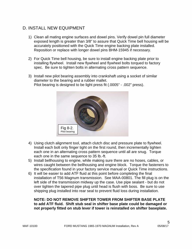
3) Install new pilot bearing assembly into crankshaft using a socket of similar
diameter to the bearing and a rubber mallet. Pilot bearing is designed to be light press fit (.0005” - .002” press).
4) Using clutch alignment tool, attach clutch disc and pressure plate to flywheel. Install each bolt only finger tight on the first round, then incrementally tighten each one in an alternating cross pattern sequence until all are snug. Torque each one in the same sequence to 35 lb.-ft.
5) Install bellhousing to engine, while making sure there are no hoses, cables, or wires caught between the bellhousing and engine block. Torque the fasteners to the specification found in your factory service manual or Quick Time instructions.
6) It will be easier to add ATF fluid at this point before completing the final installation of T56 Magnum transmission. See MAA-00801. The fill plug is on the left side of the transmission midway up the case. Use pipe sealant - but do not over tighten the tapered pipe plug until head is flush with boss. Be sure to use shipping plug installed into rear seal to prevent fluid loss during installation. NOTE: DO NOT REMOVE SHIFTER TOWER FROM SHIFTER BASE PLATE to add ATF fluid. Shift stub seal in shifter base plate could be damaged or not properly fitted on stub lever if tower is reinstalled on shifter baseplate.
Fig 8-2. Pilot bearing
6 MAF-10100 FORD MUSTANG 1965-1970 MAGNUM Installation, Rev A 05/08/17
7) At this point, install a SST Hydraulic system (available separately) following instructions provided, MAM-00201.
8) When installing T56 Magnum transmission, use caution when inserting the input shaft into the clutch disc and pilot bearing. Do not allow weight of transmission to rest on assembly until fully engaged (doing so can misalign disc or damage pilot bearing).
DO NOT UNDER ANY CIRCUMSTANCES use the transmission-to-bellhousing bolts to draw/pull the transmission up to the bellhousing! This could damage the input shaft of the transmission and is not covered by Silver Sport Transmissions’ Warranty. If the transmission will not slide up to the bellhousing, there is a problem. Stop and call Silver Sport Transmissions for a consultation.
9) Once the transmission is fully seated by hand against the bellhousing, fasten with bolts provided (HWG-PACK A T56).
10) Raise up engine/transmission until transmission contacts the top of the tunnel. 11) Re-install crossmember, lower the transmission fully onto crossmember, and
attach to isolator mount with washers and nuts from Hardware Pack HWF-Pack A. Confirm no interference to car body or noise will occur as the driveline moves under load.
12) Remove shipping plug, and insert drive shaft slip yoke fully until touching transmission seal rubber dust boot. Set driveshaft into position at differential and seat u-joints into differential pinion yoke. Make certain all parts are clean and properly assembled.
13) Install straps and torque to factory specs: 17 lb-ft for 1310/1330 U-bolts; 24 lb-ft for 1350 U-bolts (excessive torque can distort bearing cap leading to premature failure). Double check your assembly.
14) This would be a good time to double check driveline operating angles to confirm front and rear angles are within recommended values. Adjust as necessary.
15) Install E-brake cables. Adjust tension per factory specs. 16) Reinstall starter if removed. 17) Splice backup light harness into original harness. The backup light switch is on
the right side of the main case.
NOTE: If the transmission stops approximately 1/2” away from seating fully against the bellhousing, install and finger-tighten bellhousing to transmission bolts. Connect clutch
linkage and depress pedal lightly while pushing transmission forward to facilitate alignment of clutch disk to input shaft and pilot bearing. DO NOT force the transmission
into engagement – damage to the pilot bearing may result. Tighten bellhousing to engine bolts once the transmission is seated against the bellhousing.
7 MAF-10100 FORD MUSTANG 1965-1970 MAGNUM Installation, Rev A 05/08/17
18) The reverse lockout solenoid needs to be wired to be energized when shifting into REV. This can be done in one of two ways: a. Wire solenoid pigtail into the brake light circuit so the reverse lockout solenoid is
energized when the brakes are applied. The reverse solenoid is at the rear of the transmission near the top of the extension housing. One wire from the reverse lockout solenoid pigtail must be grounded and can be connected to the crossmember.
b. Wire solenoid pigtail into the optional ELAP-T56RLO lockout control module. See instructions included with the module kit.
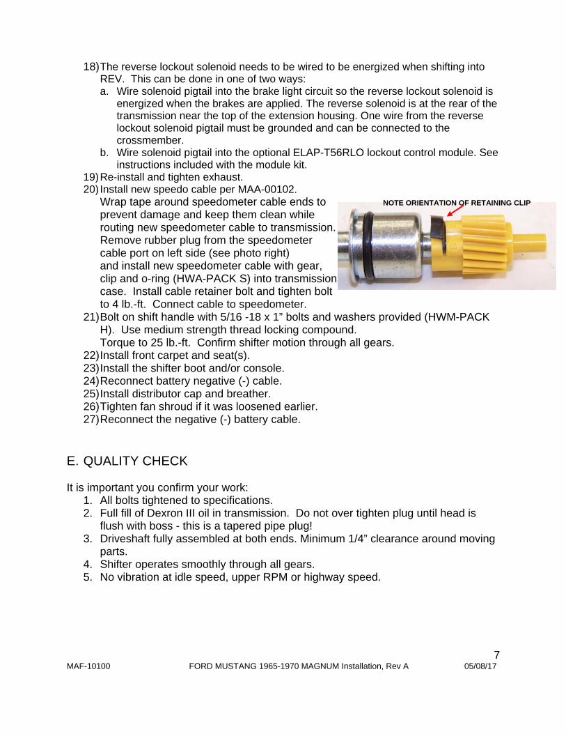
19) Re-install and tighten exhaust. 20) Install new speedo cable per MAA-00102.
Wrap tape around speedometer cable ends to prevent damage and keep them clean while routing new speedometer cable to transmission. Remove rubber plug from the speedometer cable port on left side (see photo right) and install new speedometer cable with gear, clip and o-ring (HWA-PACK S) into transmission case. Install cable retainer bolt and tighten bolt to 4 lb.-ft. Connect cable to speedometer.
21) Bolt on shift handle with 5/16 -18 x 1” bolts and washers provided (HWM-PACK H). Use medium strength thread locking compound. Torque to 25 lb.-ft. Confirm shifter motion through all gears.
22) Install front carpet and seat(s). 23) Install the shifter boot and/or console. 24) Reconnect battery negative (-) cable. 25) Install distributor cap and breather. 26) Tighten fan shroud if it was loosened earlier. 27) Reconnect the negative (-) battery cable.
E. QUALITY CHECK It is important you confirm your work:
1. All bolts tightened to specifications. 2. Full fill of Dexron III oil in transmission. Do not over tighten plug until head is
flush with boss - this is a tapered pipe plug! 3. Driveshaft fully assembled at both ends. Minimum 1/4” clearance around moving
parts. 4. Shifter operates smoothly through all gears. 5. No vibration at idle speed, upper RPM or highway speed.
NOTE ORIENTATION OF RETAINING CLIP
8 MAF-10100 FORD MUSTANG 1965-1970 MAGNUM Installation, Rev A 05/08/17
F. FINAL INSPECTION AND START UP PROCEDURE
Start engine and let idle for 2 minutes. Slowly rev engine in neutral and listen for odd noises. Feel for vibration in
driveline. With clutch disengaged, shift through all gears. Do not shift into reverse at
RPM higher than idle. Test drive at low speeds and low RPMs. Gradually test higher RPMs, then
higher speeds. If you experience a vibration at cruising speeds, it may be necessary to adjust
the rear end angle to achieve the correct driveshaft angle. Please refer to factory manuals for measurement and adjustment methods.
If you experience a vibration at zero speed, as you rev up engine with clutch released, a faulty flywheel/clutch plate balance may exist. If vibration occurs when depressing the clutch pedal only a release bearing may be faulty.
Reverse is synchronized and uses a reverse lockout solenoid wired into the brake light wiring to ensure the vehicle is stopped prior to engaging reverse.
Drive easy for 500 mile break-in period. Change oil at 30,000 miles. Spare parts are available from SST
or an authorized TREMEC distributor.
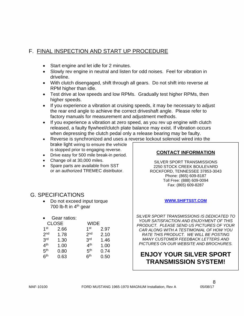
G. SPECIFICATIONS
Do not exceed input torque 700 lb-ft in 4th gear
Gear ratios: CLOSE WIDE
1st 2.66 1st 2.97 2nd 1.78 2nd 2.10 3rd 1.30 3rd 1.46 4th 1.00 4th 1.00 5th 0.80 5th 0.74 6th 0.63 6th 0.50
CONTACT INFORMATION
SILVER SPORT TRANSMISSIONS 2250 STOCK CREEK BOULEVARD
ROCKFORD, TENNESSEE 37853-3043 Phone: (865) 609-8187
Toll Free: (888) 609-0094 Fax: (865) 609-8287
WWW.SHIFTSST.COM
SILVER SPORT TRANSMISSIONS IS DEDICATED TO YOUR SATISFACTION AND ENJOYMENT OF THIS
PRODUCT. PLEASE SEND US PICTURES OF YOUR CAR ALONG WITH A TESTIMONIAL OF HOW YOU
RATE THIS PRODUCT. WE WILL BE POSTING MANY CUSTOMER FEEDBACK LETTERS AND
PICTURES ON OUR WEBSITE AND BROCHURES.
ENJOY YOUR SILVER SPORT TRANSMISSION SYSTEM!