Embed Size (px)
Citation preview

Classic Instruments
1965 – 1966 Ford Mustang
Installation Manual
Revised: December 18, 2018 Page 2
TableofContentsWelcome from the Team at Classic Instruments! .............................................................................................................. 3
Mounting the Gauges ......................................................................................................................................................... 4
Speedometer Wiring ........................................................................................................................................................... 6
Speedometer Wiring Diagram ........................................................................................................................................................ 6
Optional Pulse Signal Generator [SN16F] Wiring ........................................................................................................................... 7
Speedometer Calibration .................................................................................................................................................... 7
Entering Calibration Mode: ............................................................................................................................................................ 8
Speedometer “Instant” Calibration: ............................................................................................................................................... 8
Speedometer “Real‐Time” Calibration: .......................................................................................................................................... 9
Speedometer “Measured Mile” Calibration: ................................................................................................................................ 10
Reset Gauge Calibration to Factory Defaults: ............................................................................................................................... 10
Ultimate Speedometer (Speedo / Tach Combo) Wiring ................................................................................................... 11
Ultimate Speedometer Wiring Diagram ....................................................................................................................................... 12
Ultimate Speedometer Calibration ................................................................................................................................... 12
Entering Calibration Mode: .......................................................................................................................................................... 13
Tachometer Cylinder Setup: ......................................................................................................................................................... 13
Tachometer Signal Type Setup: .................................................................................................................................................... 14
Speedometer “Instant” Calibration: ............................................................................................................................................. 14
Speedometer “Real‐Time” Calibration: ........................................................................................................................................ 15
Speedometer “Measured Mile” Calibration: ................................................................................................................................ 15
Optional Shift Indicator Setup: ..................................................................................................................................................... 16
Reset Gauge Calibration to Factory Defaults: ............................................................................................................................... 16
Fuel, Oil Pressure, Temperature & Volt Gauge Wiring ................................................................................................... 17
Oil Pressure Sender Installation ....................................................................................................................................... 18
Temperature Sender Installation ...................................................................................................................................... 18

Revised: December 18, 2018 Page 3
Welcome from the Team at Classic Instruments! Our congratulations and appreciation for your purchase of one of the finest quality sets of specialty instruments
ever produced! Your instrument set has been conceived, designed, and manufactured by Classic Instruments, Inc. in the U.S.A. Each instrument has been tested and certified for accuracy and quality before packaging and shipping.
For trouble-free installation and operation follow the instructions exactly as outlined. Your instruments were assembled to precise specifications and although each has a seven (7) year warranty covering defective parts and workmanship – this warranty will not cover instruments or sender units which have been installed incorrectly.
Follow our recommended procedures for installation and proper hookup to maintain the value and appearance of your instrument set during many future years of accurate and dependable service!
LIMITED WARRANTY
Classic Instruments, Inc. (CI) warrants to the original purchaser that any CI product manufactured or supplied by CI will be free from defects in material and workmanship under normal use and service for a period of seven (7) years from date of purchase.
Improper installation, use of sending units other than CI’s or attempted repair or adjustments by other than CI shall void this warranty. Disassembly of any instruments or senders for whatever reason shall specifically void this warranty.
It’s always easy to look to a part for an issue with your set. Before you conclude that a part may be bad, thoroughly check your work. Today’s semiconductors and passive components have reached incredibly high reliability levels, but there is still room for error in our human construction skills. However, on rare occasions a sour part can slip through. Please be aware that testing can usually determine if the part was truly defective or damaged by assembly or usage. Don’t be afraid of telling us that you “blew it”, we’re all human and in most cases, replacement parts are very reasonably priced.
Purchaser requesting a product to be repaired or replaced under warranty must first call CI at 1-800-575-0461 before the return of defective part. Send defective part to 826 Moll Drive, Boyne City, MI 49712, USA. Include a written description of the failure with defective part.
Purchaser agrees and accepts that under no circumstances will a warranty replacement be furnished until CI has first received, inspected, and tested the returned part.
All other warranties expressed or implied are hereby excluded including any implied warranty of merchandise and implied warranty of fitness for a particular purpose. The sole and exclusive remedy for breach of this warranty is limited to the replacement set forth above.
It is expressly agreed that there shall be no further remedy for consequential or other type of damage, including any claim for loss of profit, engine damage or injury.
TECHNICAL ASSISTANCE 1-800-575-0461
OR Visit our website for the latest in gauge design and updates to our installation manual
www.classicinstruments.com

Revised: December 18, 2018 Page 4
Mounting the Gauges Required Parts:
Classic Instruments 1965-66 Mustang 5 gauge kit or Ultimate Speedometer kit Mustang Adapter Panels 1965-66 Ford Mustang Gauge Bezel
Required Tools: #1 Phillips screwdriver #2 Phillips screwdriver 11/32” nut driver or socket and ratchet Side cutters
Required Hardware: Four 6-32 x 1/2” F-type self-tapping screws Four 6-32 x 1” F-type self-tapping screws Ten 10-32 x 1” machine screws Four 10-32 x ¼” machine screws Four 7/16” Aluminum Spacers One 3 ½” rubber O-ring
Steps: 1. Place the gauge bezel face down. 2. Remove the plastic pin at the top of the speedometer
opening with side cutters or pliers. See Figure 1. 3. Place the gauges face down in the desired locations on
the gauge bezel. 4. Put the supplied 3 ½” o-ring around the speedometer
housing if using a Scott Drake reproduction housing. If using an OEM housing the o-ring is not required.
5. Place the aluminum adapter panel over the gauges. The panel will only fit correctly one way. The passenger side of the panel has one half-circle notch and the bottom has two half-circle notches. See Figure 2.
VIEW FROMBACK
Notch on passenger side
BOTTOM
Figure 2: Aluminum Adapter Panel
Figure 1
Revised: December 18, 2018 Page 5
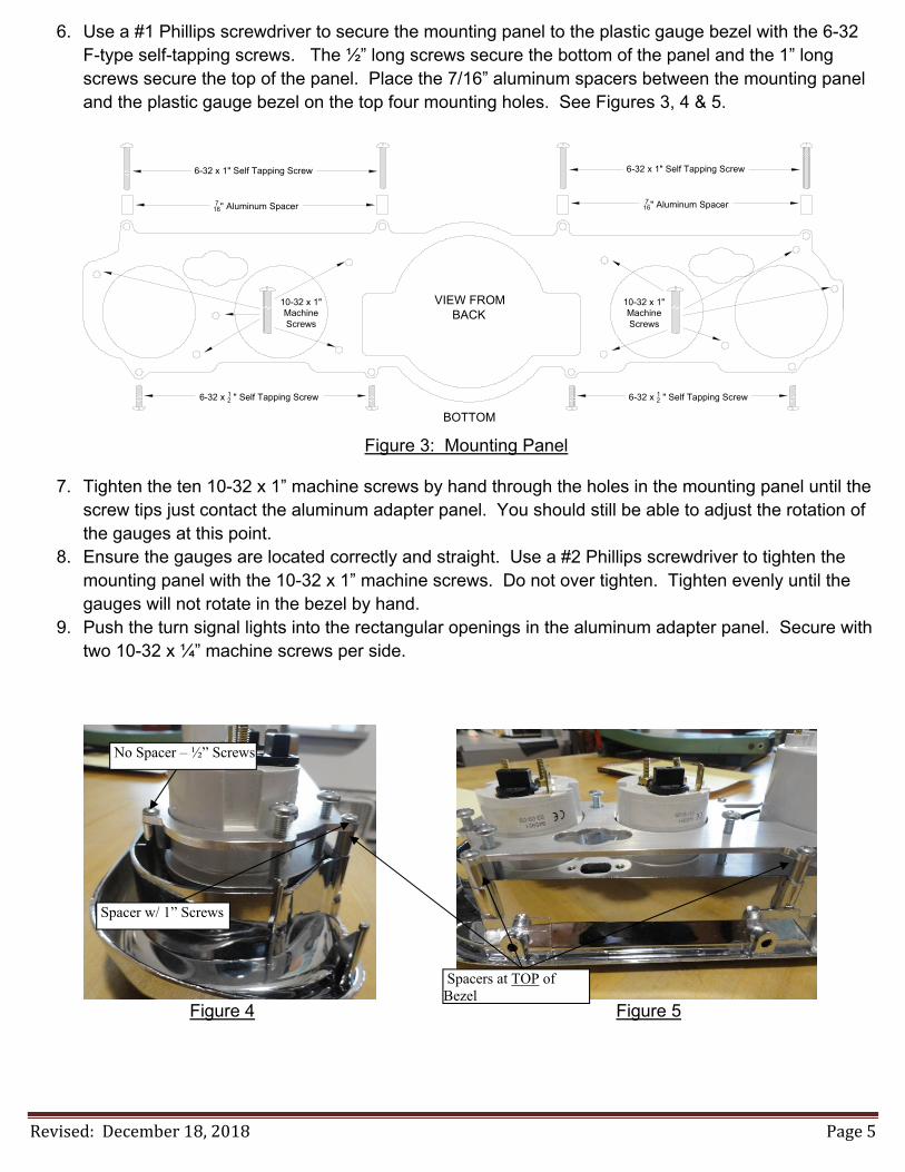
6. Use a #1 Phillips screwdriver to secure the mounting panel to the plastic gauge bezel with the 6-32 F-type self-tapping screws. The ½” long screws secure the bottom of the panel and the 1” long screws secure the top of the panel. Place the 7/16” aluminum spacers between the mounting panel and the plastic gauge bezel on the top four mounting holes. See Figures 3, 4 & 5.
VIEW FROMBACK
BOTTOM
6-32 x 1" Self Tapping Screw
716" Aluminum Spacer
6-32 x 1" Self Tapping Screw
716" Aluminum Spacer
6-32 x 12 " Self Tapping Screw 6-32 x 12 " Self Tapping Screw
10-32 x 1"MachineScrews
10-32 x 1"MachineScrews
Figure 3: Mounting Panel
7. Tighten the ten 10-32 x 1” machine screws by hand through the holes in the mounting panel until the
screw tips just contact the aluminum adapter panel. You should still be able to adjust the rotation of the gauges at this point.
8. Ensure the gauges are located correctly and straight. Use a #2 Phillips screwdriver to tighten the mounting panel with the 10-32 x 1” machine screws. Do not over tighten. Tighten evenly until the gauges will not rotate in the bezel by hand.
9. Push the turn signal lights into the rectangular openings in the aluminum adapter panel. Secure with two 10-32 x ¼” machine screws per side.
Figure 4 Figure 5
Spacers at TOP of Bezel
No Spacer – ½” Screws
Spacer w/ 1” Screws

Revised: December 18, 2018 Page 6
Speedometer Wiring
1) Always disconnect the ground lead from the vehicle battery before wiring any gauge. 2) Connect a switched +12VDC power source to the Pink wire of the gauge harness. We
recommend using a dedicated power source for the speedometer to avoid possible problems caused by interference.
3) Connect a good chassis ground to the Black wire of the gauge harness. We recommend using a dedicated chassis ground (not stacked with other ground wires) to avoid possible problems caused by a bad ground.
4) Connect dash light power to the Grey wire of the gauge harness. 5) Connect a speed signal to the Purple wire of the gauge harness:
a. White signal wire from a Classic Instruments pulse signal generator (SN16F) i. Connect the Black wire of the pulse signal generator to a good chassis ground. ii. Connect the Red wire of the pulse signal generator to the Red wire of the gauge
harness. [OR]
b. One (either) wire of an electronic transmission’s 2-wire vehicle speed sensor [VSS]. i. Connect the other VSS wire to the same ground used for the gauge.
[OR] c. Speedometer Signal wire of the vehicle computer [PCM].
i. Also set the filter switch next to the gauge plug to ON. 6) Connect one wire of the speedometer calibration button to the Brown wire of the gauge
harness. a. Connect the other wire of the calibration button to a good chassis ground.
7) Connect high beam indicator power to the Lt. Green wire of the gauge harness. 8) The Blue / White, Purple / White, White, Blue and Yellow wires of the gauge harness
are NOT USED.
Speedometer Wiring Diagram
Filter Switch
ON: ECM or SN16 SpeedSignals
OFF: VSS or SN96 SpeedSignals
OFF ON
5VDC Output for SN16 (if used) [RED]+Dash Lights Power [GREY]
Speedometer Signal [PURPLE]
Not Used [BLUE / WHITE]
Good Chassis Ground [BLACK]
High Beam Indicator [LT. GREEN]
Not Used [PURPLE / WHITE]
Setup Button Connection [BROWN]
Not Used [WHITE]
Not Used [BLUE]ACC
+12VDC Switched Power [PINK]
Not Used [YELLOW]
Revised: December 18, 2018 Page 7
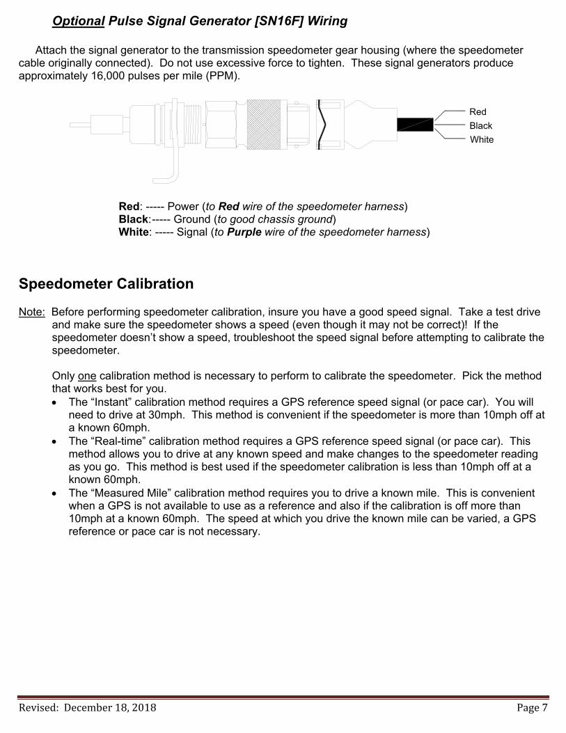
Optional Pulse Signal Generator [SN16F] Wiring
Attach the signal generator to the transmission speedometer gear housing (where the speedometer cable originally connected). Do not use excessive force to tighten. These signal generators produce approximately 16,000 pulses per mile (PPM).
Red
Black
White
Red: ----- Power (to Red wire of the speedometer harness) Black: ----- Ground (to good chassis ground) White: ----- Signal (to Purple wire of the speedometer harness)
Speedometer Calibration Note: Before performing speedometer calibration, insure you have a good speed signal. Take a test drive
and make sure the speedometer shows a speed (even though it may not be correct)! If the speedometer doesn’t show a speed, troubleshoot the speed signal before attempting to calibrate the speedometer.
Only one calibration method is necessary to perform to calibrate the speedometer. Pick the method
that works best for you. The “Instant” calibration method requires a GPS reference speed signal (or pace car). You will
need to drive at 30mph. This method is convenient if the speedometer is more than 10mph off at a known 60mph.
The “Real-time” calibration method requires a GPS reference speed signal (or pace car). This method allows you to drive at any known speed and make changes to the speedometer reading as you go. This method is best used if the speedometer calibration is less than 10mph off at a known 60mph.
The “Measured Mile” calibration method requires you to drive a known mile. This is convenient when a GPS is not available to use as a reference and also if the calibration is off more than 10mph at a known 60mph. The speed at which you drive the known mile can be varied, a GPS reference or pace car is not necessary.
Revised: December 18, 2018 Page 8
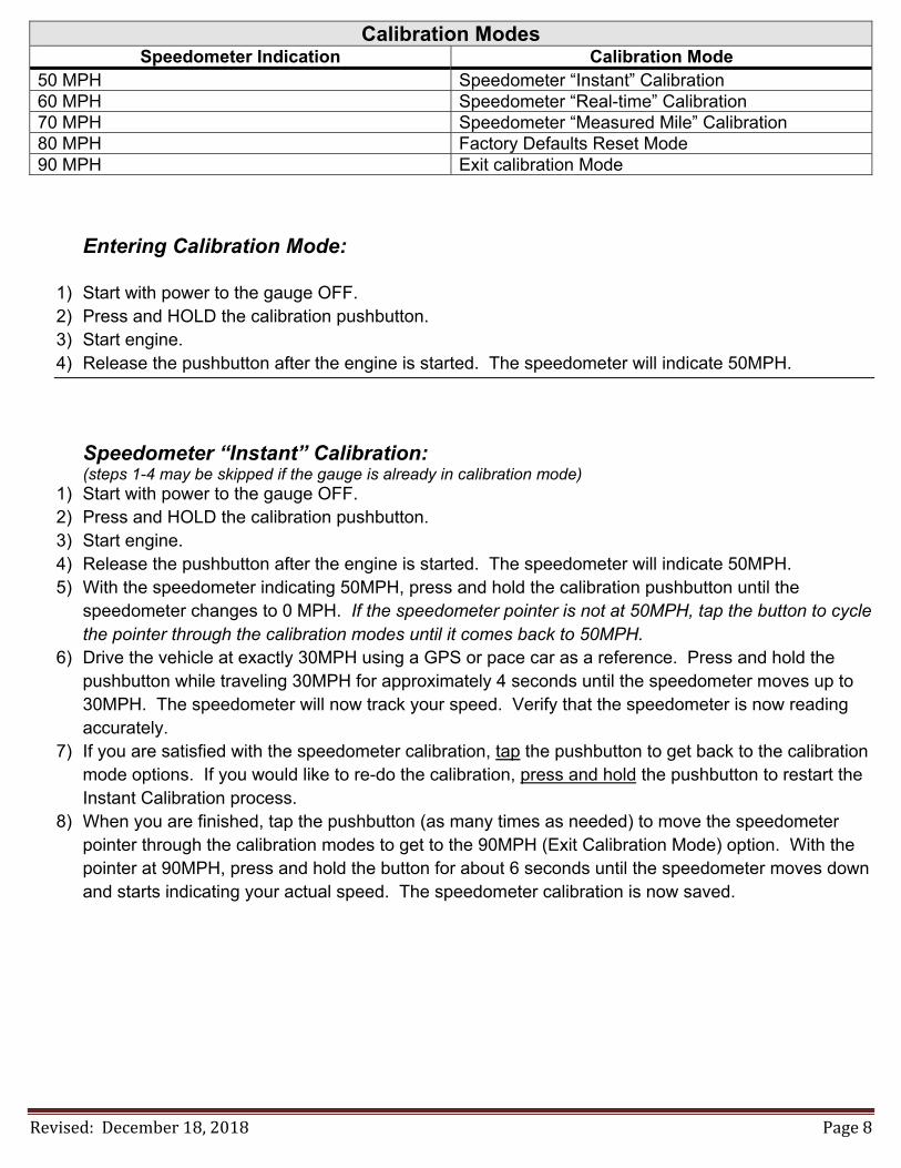
Calibration Modes Speedometer Indication Calibration Mode
50 MPH Speedometer “Instant” Calibration 60 MPH Speedometer “Real-time” Calibration 70 MPH Speedometer “Measured Mile” Calibration 80 MPH Factory Defaults Reset Mode 90 MPH Exit calibration Mode
Entering Calibration Mode:
1) Start with power to the gauge OFF. 2) Press and HOLD the calibration pushbutton. 3) Start engine. 4) Release the pushbutton after the engine is started. The speedometer will indicate 50MPH.
Speedometer “Instant” Calibration: (steps 1-4 may be skipped if the gauge is already in calibration mode)
1) Start with power to the gauge OFF. 2) Press and HOLD the calibration pushbutton. 3) Start engine. 4) Release the pushbutton after the engine is started. The speedometer will indicate 50MPH. 5) With the speedometer indicating 50MPH, press and hold the calibration pushbutton until the
speedometer changes to 0 MPH. If the speedometer pointer is not at 50MPH, tap the button to cycle the pointer through the calibration modes until it comes back to 50MPH.
6) Drive the vehicle at exactly 30MPH using a GPS or pace car as a reference. Press and hold the pushbutton while traveling 30MPH for approximately 4 seconds until the speedometer moves up to 30MPH. The speedometer will now track your speed. Verify that the speedometer is now reading accurately.
7) If you are satisfied with the speedometer calibration, tap the pushbutton to get back to the calibration mode options. If you would like to re-do the calibration, press and hold the pushbutton to restart the Instant Calibration process.
8) When you are finished, tap the pushbutton (as many times as needed) to move the speedometer pointer through the calibration modes to get to the 90MPH (Exit Calibration Mode) option. With the pointer at 90MPH, press and hold the button for about 6 seconds until the speedometer moves down and starts indicating your actual speed. The speedometer calibration is now saved.

Revised: December 18, 2018 Page 9
Speedometer “Real-Time” Calibration: (steps 1-4 may be skipped if the gauge is already in calibration mode)
1) Start with power to the gauge OFF. 2) Press and HOLD the calibration pushbutton. 3) Start engine. 4) Release the pushbutton after the engine is started. The speedometer will indicate 50MPH. 5) Tap the calibration pushbutton once to move the speedometer pointer up to 60MPH. If you missed
stopping the pointer at 60MPH, continue to tap the button to cycle the pointer through the calibration modes until it comes back to 60MPH.
6) With the speedometer indicating 60MPH, press and hold the calibration pushbutton until the speedometer changes to 0 MPH.
7) Begin driving a known speed using a GPS or pace vehicle as a reference. 8) Press and hold the pushbutton to slowly change the indicated speed. The first time the button is
pressed will increase the speedometer reading. The next time the button is pressed will decrease the speedometer reading. The speedometer will alternate between increasing and decreasing speed each time the button is pressed and held.
9) Continue to press and hold the pushbutton until the speedometer is indicating the correct speed. 10) Once the correct speed is dialed in on the speedometer, wait 8 seconds without pressing the
pushbutton to have the current calibration saved. If you still need to adjust the speed after this 8 second timeout, press and hold the button to re-enter the “Real Time” calibration mode again.
11) If you are satisfied with the speedometer calibration, tap the pushbutton (as many times as needed) to move the speedometer pointer through the calibration modes to get to the 90MPH (Exit Calibration Mode) option. With the pointer at 90MPH, press and hold the button for about 6 seconds until the speedometer moves down and starts indicating your actual speed. The speedometer calibration is now saved.
Revised: December 18, 2018 Page 10
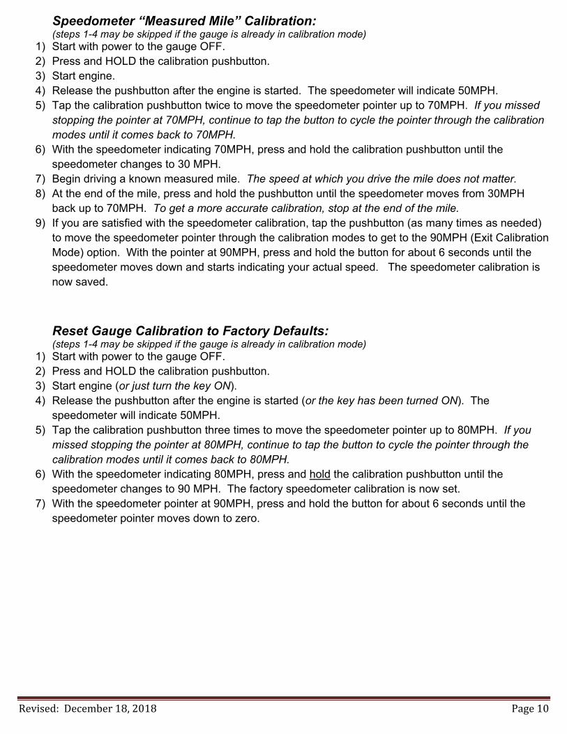
Speedometer “Measured Mile” Calibration: (steps 1-4 may be skipped if the gauge is already in calibration mode)
1) Start with power to the gauge OFF. 2) Press and HOLD the calibration pushbutton. 3) Start engine. 4) Release the pushbutton after the engine is started. The speedometer will indicate 50MPH. 5) Tap the calibration pushbutton twice to move the speedometer pointer up to 70MPH. If you missed
stopping the pointer at 70MPH, continue to tap the button to cycle the pointer through the calibration modes until it comes back to 70MPH.
6) With the speedometer indicating 70MPH, press and hold the calibration pushbutton until the speedometer changes to 30 MPH.
7) Begin driving a known measured mile. The speed at which you drive the mile does not matter. 8) At the end of the mile, press and hold the pushbutton until the speedometer moves from 30MPH
back up to 70MPH. To get a more accurate calibration, stop at the end of the mile. 9) If you are satisfied with the speedometer calibration, tap the pushbutton (as many times as needed)
to move the speedometer pointer through the calibration modes to get to the 90MPH (Exit Calibration Mode) option. With the pointer at 90MPH, press and hold the button for about 6 seconds until the speedometer moves down and starts indicating your actual speed. The speedometer calibration is now saved.
Reset Gauge Calibration to Factory Defaults: (steps 1-4 may be skipped if the gauge is already in calibration mode)
1) Start with power to the gauge OFF. 2) Press and HOLD the calibration pushbutton. 3) Start engine (or just turn the key ON). 4) Release the pushbutton after the engine is started (or the key has been turned ON). The
speedometer will indicate 50MPH. 5) Tap the calibration pushbutton three times to move the speedometer pointer up to 80MPH. If you
missed stopping the pointer at 80MPH, continue to tap the button to cycle the pointer through the calibration modes until it comes back to 80MPH.
6) With the speedometer indicating 80MPH, press and hold the calibration pushbutton until the speedometer changes to 90 MPH. The factory speedometer calibration is now set.
7) With the speedometer pointer at 90MPH, press and hold the button for about 6 seconds until the speedometer pointer moves down to zero.
Revised: December 18, 2018 Page 11
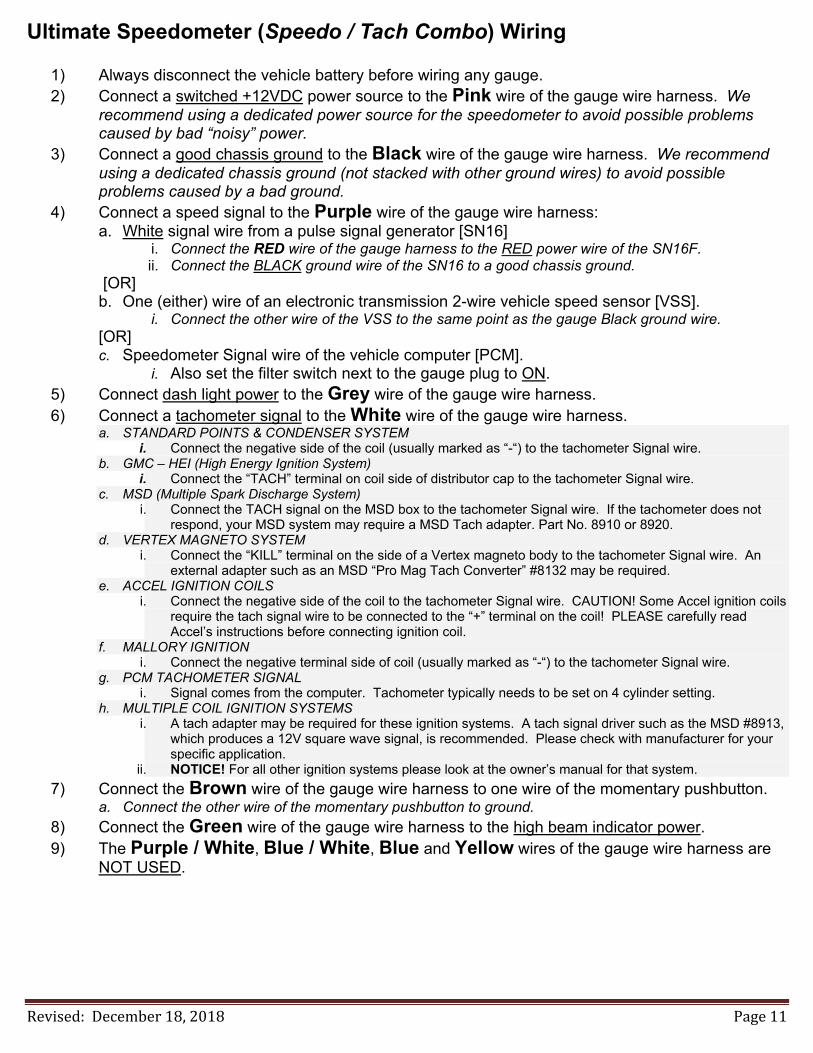
Ultimate Speedometer (Speedo / Tach Combo) Wiring
1) Always disconnect the vehicle battery before wiring any gauge. 2) Connect a switched +12VDC power source to the Pink wire of the gauge wire harness. We
recommend using a dedicated power source for the speedometer to avoid possible problems caused by bad “noisy” power.
3) Connect a good chassis ground to the Black wire of the gauge wire harness. We recommend using a dedicated chassis ground (not stacked with other ground wires) to avoid possible problems caused by a bad ground.
4) Connect a speed signal to the Purple wire of the gauge wire harness: a. White signal wire from a pulse signal generator [SN16]
i. Connect the RED wire of the gauge harness to the RED power wire of the SN16F. ii. Connect the BLACK ground wire of the SN16 to a good chassis ground.
[OR] b. One (either) wire of an electronic transmission 2-wire vehicle speed sensor [VSS].
i. Connect the other wire of the VSS to the same point as the gauge Black ground wire. [OR] c. Speedometer Signal wire of the vehicle computer [PCM].
i. Also set the filter switch next to the gauge plug to ON. 5) Connect dash light power to the Grey wire of the gauge wire harness. 6) Connect a tachometer signal to the White wire of the gauge wire harness.
a. STANDARD POINTS & CONDENSER SYSTEM i. Connect the negative side of the coil (usually marked as “-“) to the tachometer Signal wire.
b. GMC – HEI (High Energy Ignition System) i. Connect the “TACH” terminal on coil side of distributor cap to the tachometer Signal wire.
c. MSD (Multiple Spark Discharge System) i. Connect the TACH signal on the MSD box to the tachometer Signal wire. If the tachometer does not
respond, your MSD system may require a MSD Tach adapter. Part No. 8910 or 8920. d. VERTEX MAGNETO SYSTEM
i. Connect the “KILL” terminal on the side of a Vertex magneto body to the tachometer Signal wire. An external adapter such as an MSD “Pro Mag Tach Converter” #8132 may be required.
e. ACCEL IGNITION COILS i. Connect the negative side of the coil to the tachometer Signal wire. CAUTION! Some Accel ignition coils
require the tach signal wire to be connected to the “+” terminal on the coil! PLEASE carefully read Accel’s instructions before connecting ignition coil.
f. MALLORY IGNITION i. Connect the negative terminal side of coil (usually marked as “-“) to the tachometer Signal wire.
g. PCM TACHOMETER SIGNAL i. Signal comes from the computer. Tachometer typically needs to be set on 4 cylinder setting.
h. MULTIPLE COIL IGNITION SYSTEMS i. A tach adapter may be required for these ignition systems. A tach signal driver such as the MSD #8913,
which produces a 12V square wave signal, is recommended. Please check with manufacturer for your specific application.
ii. NOTICE! For all other ignition systems please look at the owner’s manual for that system.
7) Connect the Brown wire of the gauge wire harness to one wire of the momentary pushbutton. a. Connect the other wire of the momentary pushbutton to ground.
8) Connect the Green wire of the gauge wire harness to the high beam indicator power. 9) The Purple / White, Blue / White, Blue and Yellow wires of the gauge wire harness are
NOT USED.
Revised: December 18, 2018 Page 12
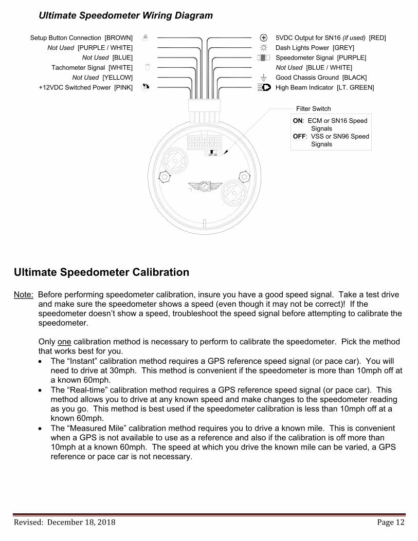
Ultimate Speedometer Wiring Diagram
Filter Switch
ON: ECM or SN16 SpeedSignals
OFF: VSS or SN96 SpeedSignals
OFF ON
5VDC Output for SN16 (if used) [RED]+Dash Lights Power [GREY]
Speedometer Signal [PURPLE]
Not Used [BLUE / WHITE]
Good Chassis Ground [BLACK]
High Beam Indicator [LT. GREEN]
Not Used [PURPLE / WHITE]
Setup Button Connection [BROWN]
Tachometer Signal [WHITE]
Not Used [BLUE]
ACC
+12VDC Switched Power [PINK]
Not Used [YELLOW]
Ultimate Speedometer Calibration
Note: Before performing speedometer calibration, insure you have a good speed signal. Take a test drive and make sure the speedometer shows a speed (even though it may not be correct)! If the speedometer doesn’t show a speed, troubleshoot the speed signal before attempting to calibrate the speedometer.
Only one calibration method is necessary to perform to calibrate the speedometer. Pick the method
that works best for you. The “Instant” calibration method requires a GPS reference speed signal (or pace car). You will
need to drive at 30mph. This method is convenient if the speedometer is more than 10mph off at a known 60mph.
The “Real-time” calibration method requires a GPS reference speed signal (or pace car). This method allows you to drive at any known speed and make changes to the speedometer reading as you go. This method is best used if the speedometer calibration is less than 10mph off at a known 60mph.
The “Measured Mile” calibration method requires you to drive a known mile. This is convenient when a GPS is not available to use as a reference and also if the calibration is off more than 10mph at a known 60mph. The speed at which you drive the known mile can be varied, a GPS reference or pace car is not necessary.

Revised: December 18, 2018 Page 13
Ultimate Speedometer Calibration Modes Tachometer Indication Calibration Mode
1000 RPM Tachometer Cylinder Setup 2000 RPM Tachometer Signal Type Setup 3000 RPM Speedometer “Instant” Calibration 4000 RPM Speedometer “Real-time” Calibration 5000 RPM Speedometer “Measured Mile” Calibration 6000 RPM Shift Indicator Setup (if equipped) 7000 RPM Factory Defaults Reset Mode 8000 RPM Exit calibration Mode
Entering Calibration Mode: 1) Start with power to the gauge OFF. 2) Press and HOLD the calibration pushbutton. 3) Start engine. 4) Release the pushbutton after the engine is started. The gauge will indicate 70MPH and 1000RPM.
Tachometer Cylinder Setup: (steps 1-4 may be skipped if the gauge is already in calibration mode)
1) Start with power to the gauge OFF. 2) Press and HOLD the calibration pushbutton. 3) Start engine. 4) Release the pushbutton after the engine is started. The gauge will indicate 70MPH and 1000RPM. 5) If necessary, tap the calibration pushbutton to index the tachometer pointer until the tachometer
indicates 1000RPM. 6) With the tachometer indicating 1000RPM, press and hold the calibration pushbutton for 6 seconds.
The speedometer pointer will move to indicate the current cylinder setting. (10MPH=1cylinder, 20MPH=2cylinder, 30MPH=3cylinder, 40MPH=4cylinder, 50MPH=5cylinder, 60MPH=6cylinder, 80MPH=8cylinder, 100MPH=10cylinder and 120MPH=12cylinder)
7) Tap the pushbutton to change the cylinder setting. The speedometer will cycle through the available settings each time the pushbutton is tapped.
8) With the speedometer indicating the desired cylinder setting, press and hold the pushbutton for 6 seconds. The gauge will indicate 70MPH and 8000RPM.
9) If you are finished calibrating the gauge, press and hold the pushbutton while the tachometer is indicating 8000RPM for 6 seconds. This will exit the calibration mode. If you want to calibrate another function of the gauge, tap the pushbutton to index the tachometer to the desired calibration mode.

Revised: December 18, 2018 Page 14
Tachometer Signal Type Setup: (steps 1-4 may be skipped if the gauge is already in calibration mode)
1) Start with power to the gauge OFF. 2) Press and HOLD the calibration pushbutton. 3) Start engine. 4) Release the pushbutton after the engine is started. The gauge will indicate 70MPH and 1000RPM. 5) Tap the calibration pushbutton to index the tachometer pointer until the tachometer indicates
2000RPM. 6) With the tachometer indicating 2000RPM, press and hold the calibration pushbutton for 6 seconds.
The speedometer pointer will move to indicate the current signal type setting. 7) Tap the pushbutton to change the signal type setting. The speedometer will cycle between the two
options each time the pushbutton is tapped. (50MPH=5V Signal, 120MPH=12V Signal) 8) Set the signal type to 5V if using a computer generated tachometer signal. Set the signal type to
12V for all other tachometer signals. 9) With the speedometer indicating the desired signal type setting, press and hold the pushbutton for 6
seconds. The gauge will indicate 70MPH and 8000RPM. 10) If you are finished calibrating the gauge, press and hold the pushbutton while the tachometer is
indicating 8000RPM for 6 seconds. This will exit the calibration mode. If you want to calibrate another function of the gauge, tap the pushbutton to index the tachometer to the desired calibration mode.
Speedometer “Instant” Calibration: (steps 1-4 may be skipped if the gauge is already in calibration mode)
1) Start with power to the gauge OFF. 2) Press and HOLD the calibration pushbutton. 3) Start engine. 4) Release the pushbutton after the engine is started. The gauge will indicate 70MPH and 1000RPM. 5) Tap the calibration pushbutton to index the tachometer pointer until the tachometer indicates
3000RPM. 6) With the tachometer indicating 3000RPM, press and hold the calibration pushbutton for 6 seconds.
The speedometer pointer will move to 0MPH. 7) Drive the vehicle at exactly 30MPH. Press and hold the pushbutton while traveling 30MPH. When
the calibration is completed, the speedometer will move to indicate 30MPH at which point the pushbutton may be released.
8) If you are satisfied with the speedometer calibration, tap the pushbutton once to get back into the main gauge calibration mode. The gauge will indicate 70MPH and 8000RPM. If you would like to re-do the calibration, simply press and hold the pushbutton while traveling 30MPH and hold the pushbutton until the speedometer indicates 30MPH at which point the pushbutton may be released.
9) When you are finished calibrating the gauge, tap the pushbutton and the gauge will indicate 70MPH and 8000RPM. Then, Press and old the pushbutton for 6 seconds. This will exit the calibration mode. If you want to calibrate another function of the gauge, tap the pushbutton to index the tachometer to the desired calibration mode.
Revised: December 18, 2018 Page 15
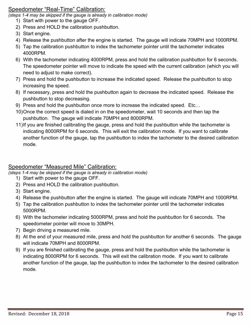
Speedometer “Real-Time” Calibration: (steps 1-4 may be skipped if the gauge is already in calibration mode)
1) Start with power to the gauge OFF. 2) Press and HOLD the calibration pushbutton. 3) Start engine. 4) Release the pushbutton after the engine is started. The gauge will indicate 70MPH and 1000RPM. 5) Tap the calibration pushbutton to index the tachometer pointer until the tachometer indicates
4000RPM. 6) With the tachometer indicating 4000RPM, press and hold the calibration pushbutton for 6 seconds.
The speedometer pointer will move to indicate the speed with the current calibration (which you will need to adjust to make correct).
7) Press and hold the pushbutton to increase the indicated speed. Release the pushbutton to stop increasing the speed.
8) If necessary, press and hold the pushbutton again to decrease the indicated speed. Release the pushbutton to stop decreasing.
9) Press and hold the pushbutton once more to increase the indicated speed. Etc… 10) Once the correct speed is dialed in on the speedometer, wait 10 seconds and then tap the
pushbutton. The gauge will indicate 70MPH and 8000RPM. 11) If you are finished calibrating the gauge, press and hold the pushbutton while the tachometer is
indicating 8000RPM for 6 seconds. This will exit the calibration mode. If you want to calibrate another function of the gauge, tap the pushbutton to index the tachometer to the desired calibration mode.
Speedometer “Measured Mile” Calibration: (steps 1-4 may be skipped if the gauge is already in calibration mode)
1) Start with power to the gauge OFF. 2) Press and HOLD the calibration pushbutton. 3) Start engine. 4) Release the pushbutton after the engine is started. The gauge will indicate 70MPH and 1000RPM. 5) Tap the calibration pushbutton to index the tachometer pointer until the tachometer indicates
5000RPM. 6) With the tachometer indicating 5000RPM, press and hold the pushbutton for 6 seconds. The
speedometer pointer will move to 30MPH. 7) Begin driving a measured mile. 8) At the end of your measured mile, press and hold the pushbutton for another 6 seconds. The gauge
will indicate 70MPH and 8000RPM. 9) If you are finished calibrating the gauge, press and hold the pushbutton while the tachometer is
indicating 8000RPM for 6 seconds. This will exit the calibration mode. If you want to calibrate another function of the gauge, tap the pushbutton to index the tachometer to the desired calibration mode.

Revised: December 18, 2018 Page 16
Optional Shift Indicator Setup: (steps 1-4 may be skipped if the gauge is already in calibration mode)
1) Start with power to the gauge OFF. 2) Press and HOLD the calibration pushbutton. 3) Start engine. 4) Release the pushbutton after the engine is started. The gauge will indicate 70MPH and 1000RPM. 5) Tap the calibration pushbutton to index the tachometer pointer until the tachometer indicates
6000RPM. 6) With the tachometer indicating 6000RPM, press and hold the pushbutton for 6 seconds. The
tachometer pointer will move to 0RPM. The shift light trigger RPM can now be set. 7) Press and hold the pushbutton to increase the tachometer reading. Release the pushbutton to stop
increasing the tachometer reading. 8) If necessary, push and hold the pushbutton again to decrease the tachometer reading. Release the
pushbutton to stop decreasing the tachometer reading. 9) Press and hold the pushbutton once more to increase the tachometer reading. Etc… 10) When the desired shift light trigger RPM is indicated on the tachometer, release the pushbutton and
wait 10 seconds. After 10 seconds of no pushbutton activity, the trigger point will be stored; the tachometer will indicate 8000RPM.
11) If you are finished calibrating the gauge, press and hold the pushbutton while the tachometer is indicating 8000RPM for 6 seconds. This will exit the calibration mode. If you want to calibrate another function of the gauge, tap the pushbutton to index the tachometer to the desired calibration mode.
Reset Gauge Calibration to Factory Defaults: (steps 1-4 may be skipped if the gauge is already in calibration mode)
1) Start with power to the gauge OFF. 2) Press and HOLD the calibration pushbutton. 3) Start engine. 4) Release the pushbutton after the engine is started. The gauge will indicate 70MPH and 1000RPM. 5) Tap the calibration pushbutton to index the tachometer pointer until the tachometer indicates
7000RPM. 6) With the tachometer indicating 7000RPM, press and hold the pushbutton for 6 seconds. The
tachometer will move to 8000RPM. 7) If you are finished calibrating the gauge, press and hold the pushbutton while the tachometer is
indicating 8000RPM for 6 seconds. This will exit the calibration mode. If you want to calibrate another function of the gauge, tap the pushbutton to index the tachometer to the desired calibration mode.
Revised: December 18, 2018 Page 17
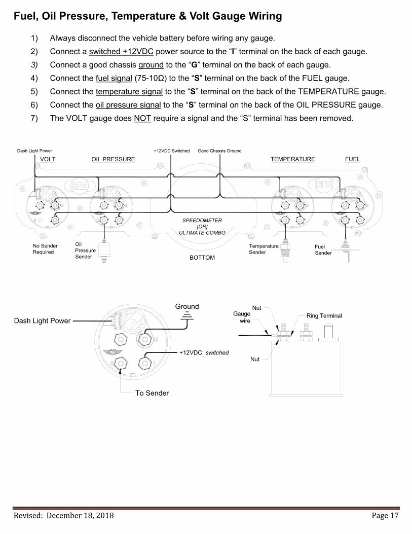
Fuel, Oil Pressure, Temperature & Volt Gauge Wiring
1) Always disconnect the vehicle battery before wiring any gauge.
2) Connect a switched +12VDC power source to the “I” terminal on the back of each gauge.
3) Connect a good chassis ground to the “G” terminal on the back of each gauge.
4) Connect the fuel signal (75-10Ω) to the “S” terminal on the back of the FUEL gauge.
5) Connect the temperature signal to the “S” terminal on the back of the TEMPERATURE gauge.
6) Connect the oil pressure signal to the “S” terminal on the back of the OIL PRESSURE gauge.
7) The VOLT gauge does NOT require a signal and the “S” terminal has been removed.
FuelSender
TemperatureSender
BOTTOM
OilPressureSender
No SenderRequired
VOLT OIL PRESSURE TEMPERATURE FUEL
SPEEDOMETER[OR]
ULTIMATE COMBO
+12VDC Switched Good Chassis GroundDash Light Power
Dash Light Power
+12VDC switched
Ground
To Sender
NutRing Terminal
Nut
Gaugewire
Revised: December 18, 2018 Page 18
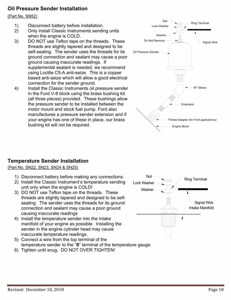
Oil Pressure Sender Installation (Part No. SN52)
1) Disconnect battery before installation. 2) Only install Classic Instruments sending units
when the engine is COLD. 3) DO NOT use Teflon tape on the threads. These
threads are slightly tapered and designed to be self-sealing. The sender uses the threads for its ground connection and sealant may cause a poor ground causing inaccurate readings. If supplemental sealant is needed, we recommend using Loctite C5-A anti-seize. This is a copper based anti-seize which will allow a good electrical connection for the sender ground.
4) Install the Classic Instruments oil pressure sender in the Ford V-8 block using the brass bushing kit (all three pieces) provided. These bushings allow the pressure sender to be installed between the motor mount and stock fuel pump. Ford also manufactures a pressure sender extension and if your engine has one of these in place, our brass bushing kit will not be required.
Temperature Sender Installation (Part No. SN22, SN23, SN24 & SN25)
1) Disconnect battery before making any connections. 2) Install the Classic Instrument’s temperature sending
unit only when the engine is COLD! 3) DO NOT use Teflon tape on the threads. These
threads are slightly tapered and designed to be self-sealing. The sender uses the threads for its ground connection and sealant may cause a poor ground causing inaccurate readings
4) Install the temperature sender into the intake manifold of your engine as possible. Installing the sender in the engine cylinder head may cause inaccurate temperature readings.
5) Connect a wire from the top terminal of the temperature sender to the “S” terminal of the temperature gauge.
6) Tighten until snug. DO NOT OVER TIGHTEN!
Signal Wire
Lock Washer
Nut
Washer
Ring Terminal
Intake Manifold
Nut
Lock Washer
Washer
Signal Wire
Oil Pressure Sender
Ring Terminal
45° Elbow
Entension
Thread Adapter (for Ford applications)
Engine Block
Do Not Remove