Embed Size (px)
Citation preview

1969-70 FORD MUSTANGWITHOUT FACTORY AIR
551170
901271 REV F 12/20/17, 1969-70 MUSTANG wo AC EVAP INST PG 1 OF 26
an ISO 9001:2015 Registered Company
18865 Goll St. San Antonio, TX 78266 Phone: 800-862-6658
Sales: [email protected] Support: [email protected]
www.vintageair.com

2901271 REV F 12/20/17, 1969-70 MUSTANG wo AC EVAP INST PG 2 OF 26
PAGES
1. 2. 3. 4. 5. 6. 7.
8. 9.
10.
11.
12. 13.
14.
15.
16.
17. 18.19. 20. 21.22.23.24.25.26.
COVERTABLE OF CONTENTSPACKING LIST/ PARTS DISCLAIMERINFORMATION PAGEWIRING NOTICE ENGINE COMPARTMENT / PASSENGER COMPARTMENT FIGURES 1 & 2DEFROST DUCT / FRESH AIR CAP & DRIVER AND PASSENGER SIDE LOUVER INSTALLATION FIGURES 3 & 4, 4aEVAPORATOR INSTALLATION FIGURES 5,5a & 6FIREWALL COVER INSTALLATION FIGURES 7 & 7a CENTER LOUVER INSTALLATION FIGURES 8 & 8aDRAIN HOSE INSTALLATION & LUBRICATING O-RINGS, STANDARD HOSE KIT & MODIFIED A/C HOSE KIT FIGURES 9 & 10HEATER HOSE & HEATER CONTROL VALVE INSTALLATION FIGURE 11 A/C & HEATER HOSE ROUTING FIGURE 12FINAL STEPS & GLOVE BOX INSTALLATION FIGURES 13 & 13a DUCT HOSE ROUTING FIGURE 14EVAPORATOR HARD LINE AND BRACKET INSTALLATION FIGURE 15 WIRING DIAGRAM
OPERATION OF CONTROLS.TROUBLE SHOOTINGTROUBLE SHOOTING CONT.DRIVER SIDE LOUVER TEMPLATEPASSENGER SIDE LOUVER TEMPLATECENTER LOUVER TEMPLATEFIREWALL COVER HOLE TEMPLATEEVAPORATOR KIT PACKING LIST
GEN IV WIRING CONNECTION INSTRUCTIONS
Table of Contents

3901271 REV F 12/20/17, 1969-70 MUSTANG wo AC EVAP INST PG 3 OF 26
FAN
DASHFLR
DEFHOT
COLD
** BEFORE BEGINNING INSTALLATION OPEN ALL PACKAGES AND CHECK CONTENTS OF SHIPMENT. PLEASE REPORT ANY SHORTAGES DIRECTLY TO VINTAGE AIR WITHIN 15 DAYS. AFTER 15 DAYS, VINTAGE AIR WILL NOT BE RESPONSIBLE FOR MISSING OR DAMAGED ITEMS.
EVAPORATOR KIT551170
1.2.
11
744004-VUE781069
GEN IV 4-VENT EVAPORATOR SUB CASE with 204 ECU 1969-70 MUSTANG without A/C GEN IV ACCESSORY KIT
NO. QTY. PART NO. DESCRIPTION
EVAPORATOR KIT PACKING LIST
1
2
GEN IV 4-VENTEVAPORATOR SUB CASE
with 204 ECU744004-VUE
ACCESSORY KIT781069 NOTE: IMAGES MAY NOT DEPICT ACTUAL PARTS AND QUANTITIES.
REFER TO PACKING LIST FOR ACTUAL PARTS AND QUANTITIES.

4901271 REV F 12/20/17, 1969-70 MUSTANG wo AC EVAP INST PG 4 OF 26
Important Notice—Please ReadFor Maximum System Performance, Vintage Air Recommends the Following:
New Vintage Air-supplied Sanden Compressor: No additional oil needed (Compressor is shipped with proper oil charge).All Other Compressors: Consult manufacturer (Some compressors are shipped dry and will need oil added).
NOTE: Vintage Air systems are designed to operate with R134a refrigerant only. Use of any other refrigerant could damage your A/C system and/or vehicle, and possibly cause a fire, in addition to potentially voiding the warranties of the A/C system and its components.
Refrigerant Capacities:Vintage Air System: 1.8 lbs. (1 lb., 12 oz.) of R134a, charged by weight with a quality charging station or scale. NOTE: Use of the proper type and amount of refrigerant is critical to system operation and performance.Other Systems: Consult manufacturer’s guidelines.
Lubricant Capacities:
Safety Switches
Service Info:Protect Your Investment: Prior to assembly, it is critical that the compressor, evaporator, A/C hoses and fittings, hardlines, condenser and receiver/drier remained capped. Removing caps prior to assembly will allow moisture, insects and debris into the components, possibly leading to reduced performance and/or premature failure of your A/C system. This is especially important with the receiver/drier. Additionally, when caps are removed for assembly, BE CAREFUL! Some components are shipped under pressure with dry nitrogen.Evacuate the System for 35-45 Minutes: Ensure that system components (Drier, compressor, evaporator and condenser) are at a temperature of at least 85° F. On a cool day, the components can be heated with a heat gun or by running the engine with the heater on before evacuating. Leak check and charge to specifications.
Your Vintage Air system is equipped with a binary pressure safety switch. A binary switch disengages the compressor clutch in cases of extreme low pressure conditions (Refrigerant Loss) or excessively high head pressure (406 PSI) to prevent compressor damage or hose rupture. A trinary switch combines Hi/Lo pressure protection with an electric fan operation signal at 254 PSI, and should be substituted for use with electric fans. Compressor safety switches are extremely important since an A/C system relies on refrigerant to circulate lubricant.
Bolts Passing Through Cowl and/or Firewall:To ensure a watertight seal between the passenger compartment and the vehicle exterior, for all bolts passing through the cowl and/or firewall, Vintage Air recommends coating the threads with silicone prior to installation.
Heater Hose (Not Included With This Kit):Heater hose may be purchased from Vintage Air (Part# 31800-VUD) or your local parts retailer. Routing and required length will vary based on installer preference.

5901271 REV F 12/20/17, 1969-70 MUSTANG wo AC EVAP INST PG 5 OF 26
Important Wiring Notice—Please Read
Some Vehicles May Have Had Some or All of Their Radio Interference Capacitors Removed. There Should Be a Capacitor Found At Each of the Following Locations:
1. On the positive terminal of the ignition coil.2. If there is a generator, on the armature terminal of the generator.3. If there is a generator, on the battery terminal of the voltage regulator.
Most alternators have a capacitor installed internally to eliminate what is called “whining” as the engine is revved. If whining is heard in the radio, or just to be extra cautious, a radio interference capacitor can be added to the battery terminal of the alternator.
It is also important that the battery lead is in good shape and that the ground leads are not compromised. There should be a heavy ground from the battery to the engine block, and additional grounds to the body and chassis.
If these precautions are not observed, it is possible for voltage spikes to be present on the battery leads. These spikes come from ignition systems, charging systems, and from switching some of the vehicle’s other systems on and off. Modern computer-operated equipment can be sensitive to voltage spikes on the power leads, which can cause unexpected resets, strange behavior, and/or permanent damage.
Vintage Air strives to harden our products against these types of electrical noise, but there is a point where a vehicle’s electrical system can be degraded so much that nothing can help.
Radio interference capacitors should be available at most auto and truck parts suppliers. They typically are cylindrical in shape, a little over an inch long, a little over a half inch in diameter, and they have a single lead coming from one end of the cylinder with a terminal on the end of the wire, as well as a mounting clip which is screwed into a good ground on the vehicle. The specific value of the capacitance is not too significant in comparison to ignition capacitors that are matched with the coil to reduce pitting of the points.
Care must be taken, when installing the compressor lead, not to short it to ground. The compressor lead must not be connected to a condenser fan or to any other auxiliary device. Shorting to ground or connecting to a condenser fan or any other auxiliary device may damage wiring, the compressor relay, and/or cause a malfunction.
When installing ground leads on Gen IV systems, the blower control ground and ECU ground must be connected directly to the negative battery post.
For proper system operation, the heater control valve must be connected to the ECU.
•
•
•

6901271 REV F 12/20/17, 1969-70 MUSTANG wo AC EVAP INST PG 6 OF 26
BEFORE STARTING THE INSTALLATION, CHECK THE FUNCTION
OF THE VEHICLE (HORN, LIGHTS,ETC.) FOR PROPER OPERATIONS. STUDY THE INSTRUCTIONS, ILLUSTRATIONS, & DIAGRAMS.
BATTERY (RETAIN).DRAIN RADIATOROEM HEATER HOSES (DISCARD).
ENGINE COMPARTMENT
REMOVE THE FOLLOWING:
REFER TO SEPARATE INSTRUCTIONS INCLUDED WITHTHE CONDENSER KIT TO INSTALL THE CONDENSER.BINARY SWITCH INSTALLATION (REFER TO CONDENSER INSTRUCTIONS)
REFER TO SEPARATE INSTRUCTIONS INCLUDED WITHTHE BRACKET KIT TO INSTALL THE COMPRESSOR BRACKET.
CONDENSER ASSEMBLY & INSTALLATION
COMPRESSOR & BRACKETS
NOTE: REMOVAL OF DASHBOARD REQUIRED TO INSTALL THE EVAPORATOR. VINTAGE AIR RECOMMENDS THAT YOU UTILIZE THE FACTORY SERVICE MANUAL WHEN YOU DISASSEMBLE AND REASSEMBLE THE DASHBOARD.
REMOVE DASH PAD, INSTRUMENT PANEL, PASSENGER SIDE PANEL AND LOWER PASSENGER SIDEDASHBOARD (RETAIN SCREWS) SEE FIGURE 1.GLOVE BOX (REATIN) SEE FIGURE 1.HEATER ASSEMBLY AND ALL RELATED DUCTING (DISCARD), RETAIN SCREWS. SEE FIGURE 2.CONTROL PANEL ASSEMBLY (RETAIN CONTROL PANEL) SEE FIGURE 1.REFER TO CONTROL PANEL CONVERSION KIT INSTRUCTIONS FOR INSTALLATION OF CONTROLS.REMOVE OEM DEFROST DUCT ASM SEE FIGURE 2.
INSTRUMENTPANEL
CONTROLPANEL
DEFROST DUCTASM
HEATER ASSMEBLY
FIGURE 1
FIGURE 2
DASH PAD
GLOVE BOX
PASSENGER SIDEPANEL
LOWER PASSENGERSIDE DASHBOARD
PASSENGER COMPARTMENT
REMOVE THE FOLLOWING:

7901271 REV F 12/20/17, 1969-70 MUSTANG wo AC EVAP INST PG 7 OF 26
TEMPLATE
SILICONE
DRILL 2 ¾”HOLE
DRIVER SIDE
PASSENGER SIDE
DRILL 2 ¾”HOLE
LOUVER490535
LOUVER BEZEL605181
LOUVER BRKT642075
2 ½” HOSEADAPTER
DASH
TEMPLATE
DEFROSTDUCT
605169
(3) 3/16”SAE FLATWASHERS
(3) OEMSTAR NUTS
DRILLHOLES
FRESH AIRCAP
605174
(3) 10 X 1/2”SHEET METAL
SCREW
INSTALL DEFROST DUCT UNDER DASH AS SHOWN IN FIGURE 3 BELOW. SECURE USING OEM NUTSw/ (3) 3/16” SAE FLAT WASHERS.HOLD FRESH AIR CAP UNDER DASH AND MARK THE (3) MOUNTING HOLES.DRILL (3) 1/8” MOUNTING HOLES UNDER DASH.APPLY A 1/4” BEAD OF SILICONE AROUND THE BACK SIDE OF THE FRESH AIR CAP AS SHOWN INFIGURE 3, BELOW.SECURE FRESH AIR CAP TO FRESH AIR HOLE USING (3) #10 x 1/2” SHEET METAL SCREWS AS SHOWNIN FIGURE 3 BELOW.
CUT OUT TEMPLATE PROVIDED ON PAGE 22. PLACE THE DRIVER SIDE TEMPLATE ON THE DASH BYALIGNING THE LEFT SIDE OF THE TEMPLATE AGAINST THE EDGE OF THE DASH, THEN ALIGN THEBOTTOM OF THE TEMPLATE TO BOTTOM OF DASH AS SHOWN IN FIGURE 4.CUT OUT TEMPLATE PROVIDED ON PAGE 23. PLACE THE PASSENGER SIDE TEMPLATE ON THE DASHBY ALIGNING THE RIGHT SIDE OF THE TEMPLATE AGAINST THE EDGE OF THE DASH, THEN ALIGNTHE BOTTOM OF THE TEMPLATE TO BOTTOM OF DASH AS SHOWN IN FIGURE 4.ONCE TEMPLATE IS ALIGNED CORRECTLY, USE A CENTER PUNCH TO MARK THE HOLE ON THEDASH. REMOVE TEMPLATE. USE A 2 ¾” HOLE SAW TO CUT HOLE IN DASH, SEE FIGURE 4 BELOW.INSTALL LOUVERS IN DASH AS SHOWN IN FIGURE 4a BELOW.
FIGURE 3
FIGURE 3 FIGURE 4a
DEFROST DUCT/ FRESH AIR CAP INSTALLATION
DRIVER AND PASSENGER SIDE LOUVER INSTALLATION

8901271 REV F 12/20/17, 1969-70 MUSTANG wo AC EVAP INST PG 8 OF 26
EVAPORATOR INSTALLATION
S B
Y
1969-70 MUSTANG w/o AC
FIREWALL COVER
HOLE TEMPLATE
THIS SIDE INSIDE OF CAR
(6) 3/16
HOLES
OEM HEATER
HOLE
BLOWER MOTOR
MOUNTING
HOLEBLOWER
MOTOR
MOUNTING
HOLE
BLOWER
MOTOR
MOUNTING
HOLE
BLOWER
MOTOR
MOUNTING
HOLE
(4) ALIGNMENT HOLES
USE TEMPLATE PROVIDED ON PAGE 25. ALIGN TEMPLATE WITH OEM BLOWER MOTOR MOUNTINGHOLES & DRILL (6) 3/16” HOLES IN FIREWALL FROM INSIDE UNDER DASH, SEE FIGURE 5a.ON A WORK BENCH, INSTALL EVAPORATOR REAR BRACKET AND HARDLINES WITH PROPERLY LUBRICATEDO-RINGS. SEE FIGURE 10, PAGE 11 AND FIGURE 15, PAGE 16.REMOVE 2 OEM HEATER PLUGS IN FIREWALL, SEE FIGURE 7, PAGE 9.INSTALL FRONT MOUNTING BRACKET ON EVAPORATOR USING (2) 1/4-20 x 1/2” HEX BOLTS AND TIGHTEN AS SHOWN IN FIGURE 5 BELOW.LIFT EVAPORATOR UNIT UP UNDER THE DASHBOARD SEE FIGURE 6. SECURE LOOSELY TO THE FIREWALL FROM THE ENGINE COMPARTMENT SIDE USING (2) 1/4-20 NUT AND WASHER, SEE FIGURE 6 BELOW.USING (2) #14 x 3/4” SHEET METAL SCREWS w/ 1/4” FLAT WASHER SECURE THE FRONT EVAPORATOR MOUNTING BRACKET TO THE INNER COWL. SEE FIGURE 6 BELOW.VERIFY THAT EVAPORATOR UNIT IS LEVEL AND SQUARE TO THE DASH, THEN TIGHTEN ALL MOUNTING BOLTS. (NOTE: TIGHTEN THE BOLT ON FIREWALL FIRST, THEN THE FRONT MOUNTING BRACKET SCREWS.)
EVAP FRONTBRKT
641271
DRIVER SIDE EVAPMOUNTING HOLE
DRIVER SIDE EVAPMOUNTING HOLE
(2) #14 x 3/4”SHEET METAL
SCREWw/ 1/4”
FLAT WASHER
PASSENGER SIDE EVAPMOUNTING HOLE
PASSENGER SIDE EVAPMOUNTING HOLE
OEM HEATERLINE HOLES
FIGURE 5
FIGURE 5a
FIGURE 6

9901271 REV F 12/20/17, 1969-70 MUSTANG wo AC EVAP INST PG 9 OF 26
SILICONE
FIREWALLCOVER642071
(6) #14 X 3/4”SHEET METAL
SCREWS
GROMMET33144-VUI
GROMMET33137-VUI
GROMMET33135-VUI
OEMHOLES
OEMHEATER HOLEIN FIREWALL
OEM HEATERLINE HOLES
(REMOVE PLUG)
(4) OEMBLOWER MOTOR
MOUNTING HOLES
INSTALL (3) GROMMETS ON FIREWALL COVER AS SHOWN IN FIGURE 7, BELOW.
APPLY A 1/4” BEAD OF SILICONE AROUND THE BACK SIDE OF THE FIREWALL COVER AS SHOWN INFIGURE 7a, BELOW.
SECURE FIREWALL COVER TO FIREWALL USING (6) #14 x 3/4” SHEET METAL SCREWS, SEE FIGURE 7,BELOW. (NOTE: FIREWALL COVER INSTALLS ON ENGINE SIDE OF FIREWALL.)
FIREWALL COVER INSTALLTION
ENGINECOMPARTMENT
SIDE OFFIREWALL
FIGURE 7a
FIGURE 7

10901271 REV F 12/20/17, 1969-70 MUSTANG wo AC EVAP INST PG 10 OF 26
ASSEMBLED VIEW
INSTALL UNDER DASH LOUVERS USING (3) #8 x 1/2” PAN HEAD SCREWS.
TEMPLATE
CUT OUT
CENTER LOUVERASM
590070
UNDER DASH LOUVER
CUT OUT CENTER LOUVER TEMPLATE PROVIDED ON PAGE 24. ALIGN CENTER LOUVER TEMPLATE ON DASH PAD AS SHOWN IN FIGURE 8a.MARK CENTER LOUVER OPENING ON DASH PAD. ONCE CENTER LOUVER OPENING IS MARKED REMOVE TEMPLATE AND CAREFULLY CUT OUT OPENING IN DASH PAD.INSTALL CENTER LOUVER ASM AS SHOWN IN FIGURE 8.
CENTER LOUVER INSTALLATION (OPTION 1)
UNDER DASH CENTER LOUVER INSTALLATION (OPTION 2)
FIGURE 8a
FIGURE 8

11901271 REV F 12/20/17, 1969-70 MUSTANG wo AC EVAP INST PG 11 OF 26
LOCATE EVAPORATOR DRAIN ON BOTTOM OF EVAPORATOR CASE.IN-LINE WITH THE DRAIN, LIGHTLY MAKE A MARK ONTHE FIREWALL. MEASURE ONE INCH DOWN AND DRILLA 5/8” HOLE THROUGH THE FIREWALL. SEE FIGURE 9.INSTALL DRAIN HOSE TO BOTTOM OF EVAPORATORUNIT AND ROUTE THROUGH FIREWALL.SEE FIGURE 9.
DRAIN HOSE INSTALLATION
DRAINFIGURE 9
DRAINHOSE
1”
LUBRICATING O-RINGS
TWIST WITHTHIS
WRENCH
HOLD WITHTHIS
WRENCH
FOR A PROPER SEAL OF FITTINGS:INSTALL SUPPLIED O-RINGS AS SHOWNAND LUBRICATE WITH SUPPLIED OIL.
FEMALENUT
MALEINSERT
SUPPLIED OILFOR O-RINGS
#6 O-RING
#8 O-RING #10 O-RING
FIGURE 10
O-RING,SLIDE OVERMALE INSERT TO SWAGED LIP
O-RING
O-RING
STANDARD HOSE KIT
MODIFIED A/C HOSE KIT
LOCATE THE #8 COMPRESSOR A/C HOSE. LUBRICATE (2) #8 O-RINGS (SEE FIGURE 10, ABOVE) AND CONNECTTHE 45° FITTING TO THE #8 DISCHARGE PORT ON THE COMPRESSOR. ROUTE THE STR FEMALE w/ 134aSERVICE PORT FITTING TO THE #8 CONDENSER HARDLINE COMING THROUGH THE RADIATOR CORE SUPPORT.SEE FIGURE 12, PAGE 13. TIGHTEN EACH FITTING CONNECTION AS SHOWN IN FIGURE 10 ABOVE.
LOCATE THE #10 COMPRESSOR A/C HOSE. LUBRICATE (2) #10 O-RINGS AND CONNECT THE 90° FEMALEw/ 134a SERVICE PORT FITTING TO THE #10 SUCTION PORT ON THE COMPRESSOR, ROUTE THE 135° FEMALEFITTING TO THE #10 EVAPORATOR HARDLINE COMING THROUGH THE FIREWALL. SEE FIGURES 11, PAGE 12 &FIGURE 12, PAGE 13. TIGHTEN EACH FITTING CONNECTION AS SHOWN IN FIGURE 10 ABOVE.(NOTE: WRAP THE #10 FITTING CONNECTIONS WITH PRESS TAPE. SEE FIGURE 11, PAGE 12 & FIGURE 12, PAGE 13.)
LOCATE THE #6 EVAP/DRIER A/C HOSE. LUBRICATE (2) #6 O-RINGS AND CONNECT THE STR FEMALE FITTINGTO THE #6 DRIER HARDLINE COMING THROUGH THE RADIATOR CORE SUPPORT. ROUTE THE 90° FEMALEFITTING TO THE #6 EVAPORATOR HARDLINE COMING THROUGH THE FIREWALL. SEE FIGURES 11, PAGE 12 &FIGURE 12, PAGE 13. TIGHTEN EACH FITTING CONNECTION AS SHOWN IN FIGURE 10, ABOVE.
USE (6) TIE WRAPS TO SECURE THE #6 A/C HOSE TO THE EXPORT BRACE AS SHOWN IN FIGURE 12, PAGE 13.
REFER TO SEPARATE INSTRUCTIONS INCLUDED WITH MODIFIED HOSE KIT.

12901271 REV F 12/20/17, 1969-70 MUSTANG wo AC EVAP INST PG 12 OF 26
HEATER HOSE & HEATER CONTROL VALVE INSTALLATION
ROUTE A PIECE OF HEATER HOSE FROM THE WATER PUMP TO THE HEATER LINE COMING THROUGH THE FIREWALLAS SHOWN IN FIGURE 11, BELOW. SECURE USING HOSE CLAMPS.
ROUTE A PIECE OF HEATER HOSE FROM THE INTAKE TO THE HEATER LINE COMING THROUGH THE FIREWALLAS SHOWN IN FIGURE 11 BELOW. NOTE: INSTALL HEATER CONTROL VALVE IN-LINE WITH INTAKE MANIFOLD(PRESSURE SIDE) HEATER HOSE, SECURE USING HOSE CLAMPS AS SHOWN IN FIGURE 11 BELOW.(NOTE PROPER FLOW DIRECTION.)
FIREWALLCOVER
642071 #6 A/C HOSE
#10 SUCTIONHOSE
O-RINGS
PRESSTAPE
FIREWALL
ECUMODULE
#10 SUCTIONLINE (INSULATED)
EXPANSIONVALVE
FIGURE 11
FROM EVAPORATOR
TO WATER PUMP
FROM INTAKEMANIFOLD
FROM HTR CNTRL VLV
TO EVAPORATOR
HEATERHOSE

13901271 REV F 12/20/17, 1969-70 MUSTANG wo AC EVAP INSTR PG 13 OF 26
OU
TIN
AC
& H
EATE
R H
OSE
RO
UTI
NG
NO
TE:
VIN
TAG
E A
IR S
YSTE
MS
REQ
UIR
E(2
) 5
/8 H
OSE
NIP
PLES
(N
OT
SUPP
LIED
)
#1
0SU
CTI
ON
H
OSE
(6)
TIE
WRA
P
HEA
TER
HO
SE(H
EATE
R C
NTR
LVA
LVE/
INTA
KE)
#8
DIS
CH
ARG
EH
OSE
INN
ER
FEN
DER
WEL
L
#8 C
ON
DEN
SER
TOC
ORE
SU
PPO
RTH
ARD
LIN
E081096
#6 D
RIER
TO
CO
RE S
UPP
ORT
HA
RDLI
NE
081095
CO
MPR
ESSO
RSA
FETY
SW
ITC
H(B
INA
RY T
YPE)
SCRE
W O
N D
RIER
(REF
ER T
OC
ON
DEN
SER
INST
RUC
TIO
NS)
CO
RESU
PPRO
RT
FIG
UR
E 12
PRES
STA
PE
HEA
TER
HO
SE(H
EATE
R C
ORE
/W
ATE
R PU
MP)
#6
HO
SE

14901271 REV F 12/20/17, 1969-70 MUSTANG wo AC EVAP INST PG 14 OF 26
GLOVE BOX
INSTALL DUCT HOSES AS SHOWN IN FIGURE 14, PAGE 15.ROUTE A/C WIRES THROUGH 3/8” GROMMET AS SHOWN IN FIGURE 13a(12 VOLT/ GROUND/ BINARY SWITCH/ HEATER VALVE).INSTALL CONTROL PANEL ASM.PLUG THE WIRING HARNESS IN THE ECU MODULE ON SUB CASE AS SHOWN IN FIGURE 14, PAGE 15(WIRE ACCORDING TO WIRING DIAGRAM ON PAGE 17 AND 18)GLOVE BOX INSTALLATION (SEE FIGURE 13)REINSTALL ALL PREVIOUSLY REMOVED ITEMS (BATTERY).FILL RADIATOR WITH AT LEAST A 50/50 MIXTURE OF APPROVED ANTIFREEZE AND DISTILLED WATER. IT IS THE OWNERS RESPONSIBILTY TO KEEP THE FREEZE PROTECTION AT THE PROPER LEVEL FOR THE CLIMATE IN WHICH THE VEHICLE IS OPERATED. FAILURE TO FOLLOW ANTIFREEZE RECOMMENDATIONS WILL CAUSE HEATER CORE TO CORRODE PREMATURELY AND POSSIBLY BURST IN AC MODE AND/ OR FREEZING WEATHER, VOIDING YOUR WARRANTY.DOUBLE CHECK ALL FITTING, BRACKETS AND BELTS FOR TIGHTNESS.VINTAGE AIR RECOMMENDS THAT ALL AC SYSTEMS BE SERVICED BY A CERTIFIED AUTOMOTIVE AIR CONDITIONING TECHNICIAN.EVACUATE THE SYSTEM FOR A MINIMUM OF 45 MINUTES PRIOR RO CHARGING AND LEAK CHECK PRIOR TO SERVICING.CHARGE THE SYSTEM TO THE CAPACITIES STATED ON THE INFORMATION PAGE (PAGE 4) OF THISINSTRUCTION MANUAL.SEE OPERATION OF CONTROLS PROCEDURES PAGE 19.
INSTALL GLOVE BOX WITH OEM SCREWS. SEE FIGURE 13.
FIGURE 13FIGURE 13a
FIREWALLCOVER
FINAL STEPS
GLOVE BOX INSTALLATION
GROMMET

15901271 REV F 12/20/17, 1969-70 MUSTANG wo AC EVAP INST PG 15 OF 26
DUCT HOSE ROUTINGS B
Y
DRIVER SIDEDEF. DUCT2” x 14”
DRIVER SIDELOUVER
2 ½” x 30”
CENTER LOUVERDRIVER SIDE2 ½” x 32”
CENTER LOUVERPASS. SIDE2 ½” x 32”
PASS. SIDEDEF. DUCT2” x 12”
PASS. SIDELOUVER
2 ½” x 32” PLUGFROM
CONTROLWIRING
HARNESS232002-VUA
PLUGFROM
WIRINGHARNESS
232600-VUA
CONTROL PANELHARNESS TO ECU
FIGURE 14

16901271 REV F 12/20/17, 1969-70 MUSTANG wo AC EVAP INSTR PG 16 OF 26
1/4
” PU
SH N
UT
BO
LT R
ETA
INER
18
91
25
-MU
R
1/4
-20
X 1
”C
OA
RSE
BO
LT1
82
89
-VU
B
BRA
CK
ET
#6
LI
QU
ID L
INE
08
10
91
EVA
PO
RA
TOR
HA
RD
LIN
E IN
STA
LLA
TIO
N
HEA
TER
LIN
E(E
VA
P TO
WA
TER
PUM
P)081094
NO
TE:
AFT
ER IN
STA
LLIN
G#
10
SU
CTI
ON
LIN
EW
RAP
ALL
EXP
OSE
D M
ETA
LFI
TTIN
GS
& T
UBE
WIT
H S
UPP
LIED
PRES
S TA
PE.
PRES
S TA
PE
F
HO
LD W
ITH
THIS
WRE
NC
H
1/4-
20 X
1/2
”BO
LT
(LO
CAT
ED O
NSU
B C
ASE
)
TWIS
T W
ITH
THIS
WRE
NC
H
#10 O
-RIN
G33859-V
UF
HEA
TER
LIN
E(E
VA
P TO
INTA
KE)
081093
ECU
MO
DU
LE
LUBR
ICAT
E O
-RIN
G(S
EE F
IGU
RE 1
0,PA
GE
11.)
#1
0 S
UC
TIO
NLI
NE
08
10
92
#6
O-R
ING
33857-V
UF
PASS
SID
E EV
AP
REA
R BR
KT6
41
27
2
DRI
VER
SID
E EV
AP
REA
R BR
KT6
41
27
3
#1
0 O
-RIN
G3
38
59
-VU
F
FIG
UR
E 16

17901271 REV F 12/20/17, 1969-70 MUSTANG wo AC EVAP INST PG 17 OF 26
WHT/GRN
WHT/YELWHT/RED
RED
WHTBACKLIGHT NEG
FAN WIPER
MODE WIPER
TEMP WIPER
5V-SW
GND
BACKLIGHT POS
AC ANNUNCIATOR
PRE-WIRED
GEN IV WIRING DIAGRAMREV D, 5/6/2014
GEN IV ECU
PROGRAM
Wiring Diagram
TEMP
MODE
FAN
A/C(IF USED)
232007-VUR
232002-VUA
** CIRCUITBREAKER30 AMP
*** WIDE OPENTHROTTLESWITCH
(OPTIONAL)
* DASH LAMP(IF USED)
Dash Lamp Is Used Only With Type 232007-VUR Harness.Warning: Always Mount Circuit Breaker As Close to the Battery As Possible. (NOTE: Wire BetweenBattery and Circuit Breaker Is Unprotected and Should Be Carefully Routed to Avoid a ShortCircuit).Wide Open Throttle Switch Contacts Close Only at Full Throttle, Which Disables A/C Compressor.
JF8
BLK
ORA
TAN
VIEWED FROM WIRE SIDE
• ••
•••
HEATERCONTROL VALVE
REVISION C 10/06/17

18901271 REV F 12/20/17, 1969-70 MUSTANG wo AC EVAP INST PG 18 OF 26
RED
CIRCUIT BREAKER30 AMP
+
+
-
BLACK
REDWHITE
RED
CHASSIS GROUND
A/CCOMPRESSOR
RELAY
Ignition Switch:
Dash Light:
NOTE: MOUNT RELAYIN DESIRED LOCATION
UNDER DASH
GREEN
FIREWALL
BLUE
BLUE
RED &
WHITE
VIOLET
(IGNITION HOTTERMINAL)
IGNITION SWITCH
DASH BACK LIGHT+0-12vTAN
GRAY
BLUE
WHITE
WHITE
REDRED
WHITE
COMPRESSOR
BATTERY
NOTE: CONNECT WHITEWIRES DIRECTLY TO
(-) BATTERY TERMINAL
BATRUN
12V
RED GREEN
RED
RED
BLUE
LATCH
BLACK
BINARYSAFETYSWITCH
YELLOW
ORANGE
WIRING HARNESS
Violet 12V Ign Switch Source (Key On Accessory) Position Must Be Switched.
Tan Wire Used Only With Vintage Air Supplied Control Panel With LED Back Light.
Binary: Connect As Shown (Typical Compressor Wiring). Be Sure Compressor Body Is Grounded.
Trinary Switch: Connect According To Trinary Switch Wiring Diagram.
Install With Servo Motor Facing Down, As Shown. Note Flow Direction Arrow Molded Into Valve Body, And Install Accordingly.
White Must Run To (-) Battery. Red May Run To (+) Battery Or Starter. Mount Circuit Breaker As Close to Battery As Possible.
Heater Control Valve:
Binary/Trinary & Compressor:
Circuit Breaker/Battery:
CONTROL WIRING HARNESS
NOTE: YELLOW & ORANGE
COMING FROM HARNESS ARE NOT
USED.
WIRING HARNESS
GRAY WIRE IS USED FOR PROGRAMING CONTROLS
IF APPLICABLE
WIRING HARNESS
Gen IV Wiring Connection Instruction
HEATERCONTROL VALVE
WARNING: ALWAYS MOUNT CIRCUIT BREAKER
AS CLOSE TO THE BATTERY AS POSSIBLE. (NOTE: WIRE BETWEEN BATTERY AND CIRCUIT BREAKER IS UNPROTECTED
AND SHOULD BE CAREFULLY ROUTED TO AVOID A SHORT CIRCUIT).
NOTE: HEATER CONTROL VALVE CONNECTION AND CHASSIS GROUND MAY BE LOCATED ON EITHER SIDE OF THE FIREWALL. ENSURECONNECTOR IS LATCHED
FIRMLY.

19901271 REV F 12/20/17, 1969-70 MUSTANG wo AC EVAP INST PG 19 OF 26
FLR
FLR
DASH
DASH
COLD
COLD
FAN
FAN
DEF
DEF
HOT
HOTFLRDASH
COLD
FAN
DEFHOT
OPERATION OF CONTROLS
BLOWER SPEED A/C THERMOSTAT LEVER
MODE LEVER
A/C MODEMODE LEVER
BLOWERSPEED
THERMOSTATLEVER
HEAT MODE DEFROST/ DE-FOG MODE
THIS LEVER CONTROLSTHE BLOWER SPEED,
FROM OFF TO HI
SLIDE THE LEVER TOTHE DASH POSITION
IN A/C MODE SLIDE THE THERMOSTAT LEVER ALL THE
WAY LEFT TO THE COLD POISTION, TO ENGAGE COMPRESSORFOR MAXIMUM COOLING
(SLIDE LEVER LEFT OR RIGHT TO ADJUSTDESIRED TEMPERATURE)
NOTE: WHEN BATTERY POWER IS FIRST CONNECTED TO THE ECU, THE COMPUTER GOES THROUGH AN INITIALIZATION SEQUENCE. THIS INITIALIZATION MAY TAKE UP TO 30 SECONDS. DURING INITIALIZATION THE BLOWER WILL NOT OPERATE, BUT THE DOORS INSIDE THE UNIT WILL BE OPERATING. A LOW BATTERY OR DISCONNECTING THE BATTERY MAY ALSO TRIGGER A RE-INITIALIZATION. DURING START UP, A LOW BATTERY MAY DROP BELOW 7 VOLTS, TRIGGERING RE-INITIALIZATION.
BLOWER SPEEDSLIDE LEVER UP TO
DESIRED BLOWER SPEED,FROM OFF TO HI
BLOWER SPEEDSLIDE LEVER UP TO
DESIRED BLOWER SPEED,FROM OFF TO HI
MODE LEVERSLIDE THE LEVER TOTHE DEF POSITION
A/C THERMOSTAT LEVER
MODE LEVERSLIDE THE LEVER TOTHE FLR POSITION
IN HEAT MODE SLIDE THE THERMOSTAT LEVER ALL THE WAY RIGHT TO THE
HOT POISTION, FOR MAXIMUM HEATING. (SLIDE LEVER LEFT OR
RIGHT TO ADJUST DESIRED TEMPERATURE)
A/C THERMOSTAT LEVERIN DEF MODE SLIDE THE THERMOSTAT LEVER ALL THE WAY LEFT TO THE COLD POISTION TO
ENGAGE COMPRESSOR. FOR MAXIMUM COOLING.
(SLIDE LEVER LEFT OR RIGHT TO ADJUST DESIRED
TEMPERATURE)

20901271 REV F 12/20/17, 1969-70 MUSTANG wo AC EVAP INSTR PG 20 OF 26
Sym
pto
m
C
on
dit
ion
C
heck
s
Act
ion
s
N
ote
s
Blo
wer
sta
ys o
n
hig
h s
pee
d w
hen
ig
nitio
n is
on.
1a.
No o
ther
funct
ions
work
.
Chec
k fo
r dam
aged
pin
s or
wires
in c
ontr
ol hea
d p
lug.
Ver
ify
that
all
pin
s ar
e in
sert
ed into
plu
g.
Ensu
re t
hat
no
pin
s ar
e ben
t or
dam
aged
in E
CU
.
Chec
k fo
r dam
aged
gro
und
wire
(white)
in c
ontr
ol hea
d
har
nes
s.
Ver
ify
continuity
to c
has
sis
gro
und w
ith w
hite
contr
ol
hea
d w
ire
at v
ario
us
poin
ts.
Loss
of gro
und o
n t
his
wire
render
s co
ntr
ol hea
d
inoper
able
.
All
oth
er f
unct
ions
work
.Chec
k fo
r dam
aged
blo
wer
sw
itch
or
pote
ntiom
eter
and
asso
ciat
ed w
irin
g.
Blo
wer
sta
ys o
n
hig
h s
pee
d w
hen
ig
nitio
n is
on o
r off.
Unplu
g 3
-wire
BSC c
ontr
ol
connec
tor
from
ECU
. If
blo
wer
sh
uts
off,
ECU
is
eith
er
impro
per
ly w
ired
or
dam
aged
.
Be
sure
the
smal
l, 2
0 G
A w
hite
gro
und w
ire
is c
onnec
ted
to t
he
bat
tery
gro
und p
ost
. If
it
is,
repla
ce t
he
ECU
.
Unplu
g 3
-wire
BSC c
ontr
ol
connec
tor
from
ECU
. If
blo
wer
st
ays
runnin
g,
BSC is
eith
er
impro
per
ly w
ired
or
dam
aged
.
Chec
k to
ensu
re t
hat
no B
SC w
irin
g is
dam
aged
or
short
ed t
o v
ehic
le g
round.
The
BSC o
per
ates
the
blo
wer
by
gro
und s
ide
puls
e w
idth
modula
tion s
witch
ing.
The
posi
tive
wire
to t
he
blo
wer
will
alw
ays
be
hot.
If th
e “g
round”
side
of
the
blo
wer
is
short
ed t
o c
has
sis
gro
und,
the
blo
wer
will
run o
n H
I.
Rep
lace
BSC (
This
will
req
uire
rem
oval
of ev
apora
tor
from
veh
icle
).N
o o
ther
par
t re
pla
cem
ents
sh
ould
be
nec
essa
ry.
Com
pre
ssor
will
not
turn
on
(All
oth
er funct
ions
work
).
2.
Sys
tem
is
not
char
ged
.Sys
tem
must
be
char
ged
for
com
pre
ssor
to e
ngag
e.Char
ge
syst
em o
r byp
ass
pre
ssure
sw
itch
.
Dan
ger:
Never
byp
ass
sa
fety
sw
itch
wit
h
en
gin
e r
un
nin
g.
Seri
ou
s in
jury
can
resu
lt.
Sys
tem
is
char
ged
.
1b
.
Tro
ub
lesh
oo
tin
g G
uid
e
Chec
k fo
r fa
ulty
A/C
pote
ntiom
eter
or
asso
ciat
ed
wirin
g (
Not
applic
able
to 3
-pot
contr
ols
).
Chec
k fo
r dis
connec
ted o
r fa
ulty
ther
mis
tor.
Chec
k co
ntinuity
to g
round o
n w
hite
contr
ol hea
d w
ire.
Chec
k fo
r 5V o
n r
ed c
ontr
ol hea
d w
ire.
Chec
k 2-p
in c
onnec
tor
at E
CU
housi
ng.
To c
hec
k fo
r pro
per
pot
funct
ion,
chec
k vo
ltag
e at
w
hite/
blu
e w
ire.
Voltag
e sh
ould
be
bet
wee
n 0
V a
nd
5V,
and w
ill v
ary
with p
ot
leve
r posi
tion.
Dis
connec
ted o
r fa
ulty
ther
mis
tor
will
cau
se
com
pre
ssor
to b
e dis
able
d.
Red
wire
at A
/C p
ot
should
hav
e ap
pro
xim
atel
y 5V
with ignitio
n o
n.
White
wire
will
hav
e co
ntinuity
to
chas
sis
gro
und.
White/
Blu
e w
ire
should
var
y bet
wee
n 0
V a
nd 5
V w
hen
le
ver
is m
oved
up o
r dow
n.
3. Com
pre
ssor
will
not
turn
off
(A
ll oth
er funct
ions
work
).
Chec
k fo
r fa
ulty
A/C
pote
ntiom
eter
or
asso
ciat
ed
wirin
g.
Chec
k fo
r fa
ulty
A/C
rel
ay.
Rep
air
or
repla
ce p
ot/
contr
ol w
irin
g.
Rep
lace
rel
ay.
See
blo
wer
sw
itch
chec
k pro
cedure
.

21901271 REV F 12/20/17, 1969-70 MUSTANG wo AC EVAP INSTR PG 21 OF 26
Sym
pto
m
C
on
dit
ion
Ch
eck
s
Act
ion
s
N
ote
s
Sys
tem
will
not
turn
on,
or
runs
inte
rmitte
ntly.
4.
Work
s w
hen
engin
e is
not
runnin
g;
shuts
off w
hen
en
gin
e is
sta
rted
(T
ypic
ally
ear
ly G
en I
V,
but
poss
ible
on a
ll ve
rsio
ns)
.
Nois
e in
terf
eren
ce f
rom
either
ig
nitio
n o
r al
tern
ator.
Inst
all ca
pac
itors
on ignitio
n c
oil
and a
lter
nat
or. E
nsu
re
good g
round a
t al
l poin
ts.
Rel
oca
te c
oil
and a
ssoci
ated
w
irin
g a
way
fro
m E
CU
and E
CU
wirin
g.
Chec
k fo
r burn
edor
loose
plu
g w
ires
.
Ver
ify
connec
tions
on p
ow
er
lead
, ig
nitio
n lea
d,
and b
oth
white
gro
und w
ires
.
Ver
ify
pro
per
met
er f
unct
ion b
y ch
ecki
ng t
he
conditio
n o
f a
know
n g
ood b
atte
ry.
Ignitio
n n
ois
e (r
adia
ted o
rco
nduct
ed)
will
cau
se t
he
syst
em t
o s
hut
dow
n d
ue
tohig
h v
oltag
e sp
ikes
. If
this
is s
usp
ecte
d,
chec
k w
ith a
qual
ity
osc
illosc
ope.
Spik
esgre
ater
than
16V w
ill s
hut
dow
n t
he
ECU
. In
stal
l a
radio
cap
acitor
at t
he
posi
tive
post
of th
e ig
nitio
nco
il (S
ee r
adio
cap
acitor
inst
alla
tion b
ulle
tin).
A
faulty
alte
rnat
or
or
worn
out
bat
tery
can
als
o r
esult
in t
his
conditio
n.
Will
not
turn
on u
nder
an
y co
nditio
ns.
Ver
ify
bat
tery
voltag
e is
gre
ater
than
10 v
olts
and les
sth
an 1
6.
Loss
of m
ode
door
funct
ion.
No m
ode
chan
ge
at a
ll.Chec
k fo
r dam
aged
mode
switch
or
pote
ntiom
eter
and
asso
ciat
ed w
irin
g.
Part
ial fu
nct
ion o
f m
ode
doors
.
Typic
ally
cau
sed b
y ev
apora
tor
housi
ng
inst
alle
d in a
bin
d in t
he
vehic
le.
Be
sure
all
mounting loca
tions
line
up
and d
on’t h
ave
to b
e fo
rced
in
to p
osi
tion.
Blo
wer
turn
s on
and o
ff r
apid
ly.
6.
Bat
tery
voltag
e is
at
leas
t 12V.
Chec
k fo
r at
lea
st 1
2V a
t ci
rcuit b
reak
er.
Ensu
re a
ll sy
stem
gro
unds
and p
ow
er c
onnec
tions
are
clea
n a
nd t
ight.
Bat
tery
voltag
e is
les
s th
an 1
2V.
5.
Tro
ub
lesh
oo
tin
g G
uid
e (
Co
nt.
)
Chec
k fo
r fa
ulty
bat
tery
or
alte
rnat
or.
Char
ge
bat
tery
.
Sys
tem
shuts
off b
low
er a
t 10V.
Poor
connec
tions
or
wea
k bat
tery
can
cau
se
shutd
ow
n a
t up t
o 1
1V.
7. When
ignitio
n is
turn
ed o
n,
blo
wer
m
om
enta
rily
co
mes
on,
then
sh
uts
off.
This
occ
urs
with t
he
blo
wer
sw
itch
in
the
OFF
posi
tion.
This
is
an indic
ator
that
the
syst
em h
as b
een r
eset
. Be
sure
the
red p
ow
er w
ire
is o
nth
e bat
tery
post
, an
d n
ot
on a
sw
itch
ed s
ourc
e. A
lso,
if
the
syst
em is
pulle
d b
elow
7V f
or
even
a s
plit
sec
ond,
the
syst
em w
ill r
eset
.
Run r
ed p
ow
er w
ire
direc
tly
to b
atte
ry.
Chec
k fo
r posi
tive
pow
er a
t hea
ter
valv
e gre
en w
ire
and
blo
wer
red
wire.
Chec
k fo
r gro
und o
n c
ontr
ol hea
d w
hite
wire.
Chec
k fo
r obst
ruct
ed o
r bin
din
g m
ode
doors
.
Chec
k fo
r dam
aged
ste
pper
m
oto
r or
wirin
g.
Err
atic
funct
ions
of
blo
wer
, m
ode,
te
mp,
etc.
Chec
k fo
r dam
aged
sw
itch
or
pot
and a
ssoci
ated
wirin
g.
Rep
air
or
repla
ce.
8.


22901271 REV F 12/20/17, 1969-70 MUSTANG wo AC EVAP INST PG 22 OF 26
DRIVER SIDE LOUVER TEMPLATE
CU
T ALO
NG
DO
TTED LIN
E
CENTER PUNCH
&DRILL
2 3/4 HOLE
1969-70 MUSTANG w/o ACDRIVER SIDE LOUVER
TEMPLATE


23901271 REV F 12/20/17, 1969-70 MUSTANG wo AC EVAP INST PG 23 OF 26
PASSENGER SIDE LOUVER TEMPLATE
CU
T ALO
NG
DO
TTED LIN
E
1969-70 MUSTANG w/o ACPASSENGER SIDE LOUVER
TEMPLATE
CENTER PUNCH
&DRILL
2 3/4 HOLE

24901271 REV F 12/20/17, 1969-70 MUSTANG wo AC EVAP INST PG 24 OF 26
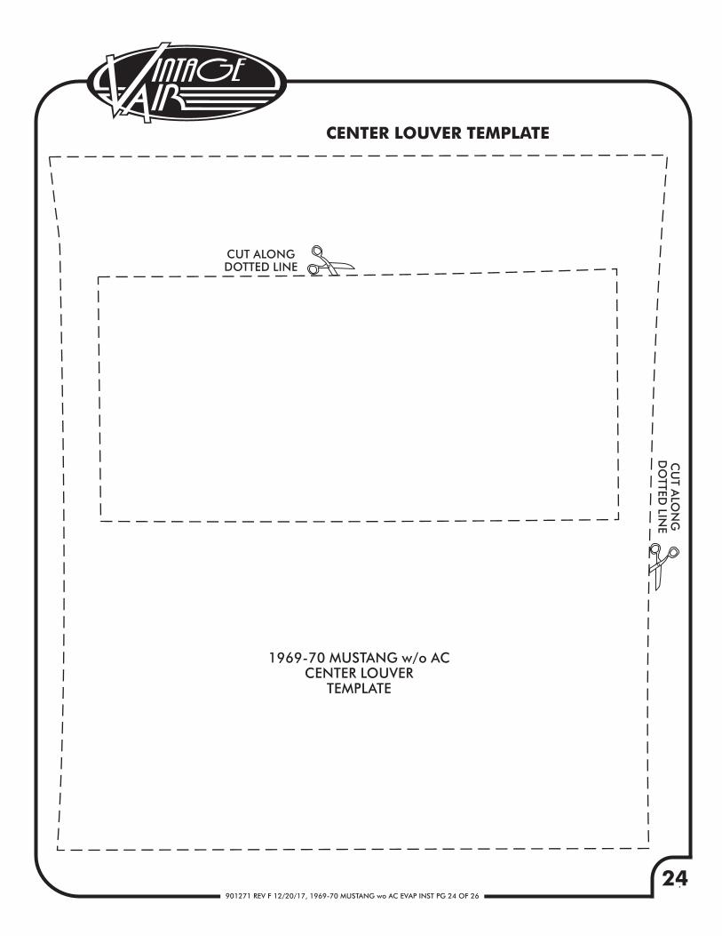
CENTER LOUVER TEMPLATE
1969-70 MUSTANG w/o ACCENTER LOUVER
TEMPLATE
CUT ALONGDOTTED LINE
CU
T ALO
NG
DO
TTED LIN
E


25901271 REV F 12/20/17, 1969-70 MUSTANG wo AC EVAP INST PG 25 OF 26
19
69
-70 M
USTA
NG
w/o A
CFIREW
ALL C
OV
ER H
OLE TEM
PLATE
THIS SID
E INSID
E OF C
AR
(6) 3
/16
HO
LES
OEM
HEA
TERH
OLE
BLOW
ER MO
TOR
MO
UN
TING
H
OLE
BLOW
ER M
OTO
RM
OU
NTIN
G
HO
LE
BLOW
ER M
OTO
RM
OU
NTIN
G
HO
LE
BLOW
ER M
OTO
RM
OU
NTIN
G
HO
LE
(4) A
LIGN
MEN
T HO
LES
CUT ALON
G
DOTTED LIN
E
CU
T ALO
NG
DO
TTED LIN
E


901271 REV F 12/20/17, 1969-70 MUSTANG wo AC EVAP INST PG 26 OF 26
CHECKED BY:PACKED BY:
DATE:
EVAPORATOR KIT551170
1.2.
11
744004-VUE781069
GEN IV 4-VENT EVAPORATOR SUB CASE with 204 ECU 1969-70 MUSTANG without A/C GEN IV ACCESSORY KIT
NO. QTY. PART NO. DESCRIPTION
EVAPORATOR KIT PACKING LIST
1
2
ACCESSORY KIT781069 NOTE: IMAGES MAY NOT DEPICT ACTUAL PARTS AND QUANTITIES.
REFER TO PACKING LIST FOR ACTUAL PARTS AND QUANTITIES.
GEN IV 4-VENTEVAPORATOR SUB CASE
with 204 ECU744004-VUE
FAN
DASHFLR
DEFHOT
COLD