Embed Size (px)
Citation preview

1971
1
• • a • • :
.. .. . " " to '
. ~. -
--- S#OP M~NUA,L

INTRODUCTION
This Manual has been prepared as a guide to maintenance, disassembly and assembly of the Polaris snowmobiles.
By reading this Manual carefully, you can obtain knowledge of the machine, which will be helpful in maintenance.
The meaning of maintenance is to perform preventive maintenance and adjustment of your snowmobile to keep it in top running condition. In accordance with the instructions supplied in this Manual, all machines should be inspected and serviced periodically.
This Manual is divided into sections showing detailed photographs, covering construction details, disassembly, inspection, maintenance, and assembly of specific parts of the machine.
POLARIS INDUSTRIES Division of textron II nc.
Service Department Roseau, Minn. ,.
j
c
c
c
TABLE OF CONTENTS
MODEL SPECIFICATIONS ... . . .................. . PLAYMATE - CHARGER - TX - MUSTANG - VOYAGER
ENGINE DATA ..... 175cc - 795cc
1 - 2
.. 3- 6
COMMON SPECIFICATIONS FOR ALL MODELS . .................. 7 TORQUE PATTERNS
CONDENSED SERVICE DATA ............................. 8
ELECTRICAL SYSTEM INFORMATION ..................... 9 - 10
WIRING SCHEMATICS .............................. 11 - 14
TROUBLE SHOOTING ................................. 15
INSTRUCTION FOR FUEL PUMP . ......... .... .......... 16 - 18 MODEL OF 62 - 24
INSTRUCTION FOR CARBURETOR ...................... 19 - 26 MODEL VM - 30
INSTRUCTION FOR POLARIS ENGINES ........ ... ......... 27 - 43 CONSTRUCTION .............................. 27 - 29 STARTING .................................... 30 REMOVAL OF ENGINE .......................... 31 - 32
. DISASSEMBLY OF ENGINE. . . . . . . . . . . . . . . . . . . . ... 33 - 36 RE - ASSEMBLY OF ENGINE ....................... 37 - 43
BODY AND TRIM ................................ 44 - 45 DISASSEMBLY OF BODY, TRIM & CONSOLE
DRIVE AND BRAKE ........... . DISASSEMBLY OF CHAINCASE
STEERING ............ . STEERING DISASSEMBLY STEERING ASSEMBLY
. .......... 46 - 47
. ................... 48
TRACK AND SUSPENSION . .............. ........... . 49 - 51 DISASSEMBLY OF TRACK & SUSPENSION ....... ........... .49 ASSEMBLY OF TRACK & SUSPENSION .................... 49 POWER SLIDE TRACK TENSION. . . . . . . . . . . . . . . . . . . . . . . 50 POWER SLIDE TRACK ALIGNMENT. . . . . . . . . . . . . . . . . . . .. 50 DRIFT SKIPPER - TRACK TENSION ........ . 51 DRIFT SKIPPER - TRACK ALIGNMENT .............. ... .. 51
en Z o ~ u u.. U W Q. en ...J W Q o :iE
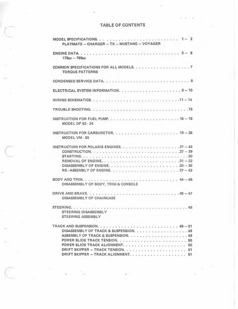
n PLAYMATE
Track Type - all rubber
Track Length on Ground - 32"
Track Width - 12"
Overall Length W/Ski - 92"
Width - 31 1/2"
Height W/Windshield - 41 1/2"
Height Less Windshield - 29"
Weight - approx. 290 Ibs.
Suspension - standard bogie
Transmission - Torque - 0 - Matic
Fuel Capacity - U.S. - 3.5 gal.
Engine - 175cc Polaris 1 cyl.
(' CHARGER
Track Type - all rubber
Track Length on Ground - 45"
Track Width - 15 1/2 "
Overall Length W/Ski - 107"
Width - 31 1/2"
Height W/VVindshield - 41"
Height Less Windshield - 29"
Weight - approx. 420 Ibs.
Suspension - Polaris Driftskipper
Transmission - Torque - 0 - Matic
Fuel Capacity - 5.9 gals.
Engine Options - 294 Polaris 2 cyl. 335 Polaris 2 cyl. 398 Polaris 2 cyl. 432 Polaris 2 cyl. 488 Polaris 2 cyl.
12 Volt electric start available on 398,432, & 488
n TX MODEL
Track Type - rubber w/steel talons
Track Length on Ground - 45"
Track Width - 15 1/2 "
Overall Length W /Ski - 107"
Width - 31 1/2"
Height W/Windshield - 40"
Height Less Eindshield - 34"
Weight - approx. 390 Ibs.
Suspension - Polaris Power Slide
Transmission - Torque - 0 . Matic
Fuel Capacity - 5.9 gal.
Engine Options - 294cc to 795cc
....
(/,)
z o le::( U u. U W 0-(/,)
..J W C o :2E
u
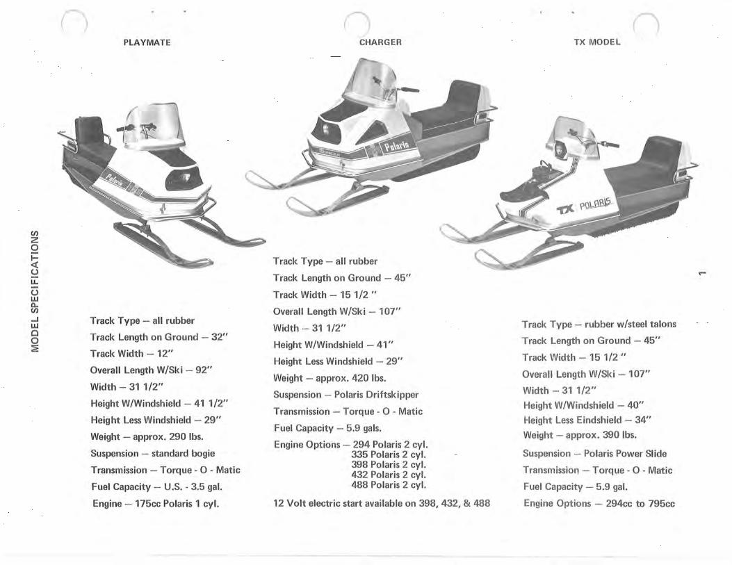
MUSTANG
Track Type - all rubber
Track Length on Ground - 45"
Track Width - 20"
Overall Length W/Ski - 110"
Width - 33"
Height W/Windshield - 45"
Height Less Windshield - 31 1/2"
Weight - approx. 475 Ibs.
Suspension - Driftskipper
Transmission - Torque - 0 - Matic
Fuel Capacity - 5.9 gals.
Engine Options - 398 Polaris 2 cyl. 488 Polaris 2 cyl.
Available with 12 volt electric start
u
VOYAGER
Track Type - rubber w/steel talons
Track Length on Ground - 45"
Track Width - 30"
Overall Length W/Ski - 108"
Width - 39 1/2"
Height W/Windshield - 49"
Height Less Windshield - 36 1/2"
Weight - approx. 590 Ibs.
Suspension - standard bogie
Transmission - forward reverse
Fuel Capacit y - 5.9 ga l.
Engine - 488cc Polaris Star 2 cycle w/electric start
o
N
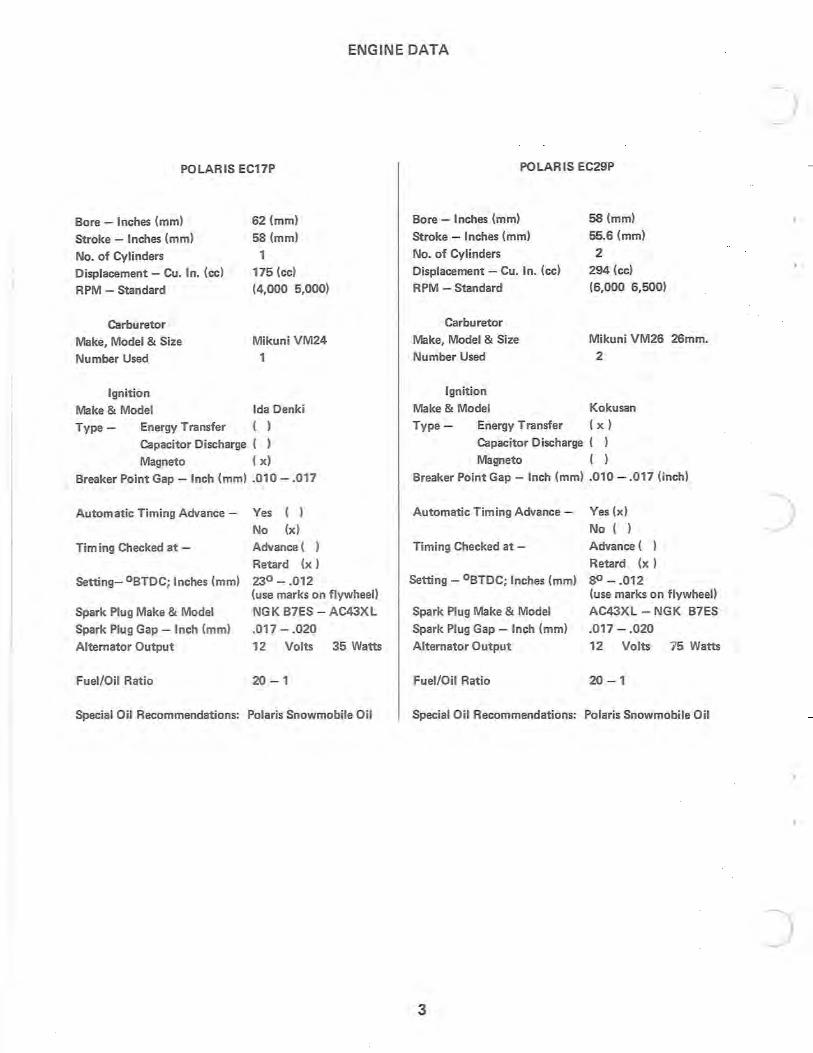
ENGINE DATA
POLARIS EC17P
Bore - Inches (mm)
Stroke - Inches (mm)
No. of Cylinders
Displacement - Cu. In. (cc)
RPM - Standard
Carburetor
Make, Model & Size
Number Used
Ignition
Make & Model
Type - Energy Transfer
62 (mm)
5S(mm)
1 175 (cc)
(4,000 5,000)
Mikuni VM24
1
Ida Denki ( )
Capacitor Discharge ( )
Magneto ( x)
Breaker Point Gap - Inch (mm) .010 - .017
Automatic Timing Advance - Yes ( ) No (x)
Tim ing Checked at -
Setting- °BTDC; Inches (mm)
Spark Plug Make & Model
Spark Plug Gap - Inch (mm)
Alternator Output
Fuel/Oil Ratio
Advance (
Retard (x)
23° - .012 (use marks on flywheel)
NGK B7ES - AC43XL
.017 - .020
12 Volts 35 Watts
20 - 1
Special Oil Recommendations: Polaris Snowmobile Oil
POLARIS EC29P
Bore - Inches (mm)
Stroke - Inches (mm)
No. of Cylinders
Displacement - Cu. In. (cc)
RPM - Standard
Carburetor
Make, Model & Size
Number Used
Ignition
5S(mm)
55.6 (mm)
2 294 (cc)
(6,000 6,500)
Mikuni VM26 26mm.
2
Make & Model Kokusan
Type - Energy Transfer ( x )
Capacitor Discharge ( )
Magneto ( )
Breaker Point Gap - Inch (mm) .010 - .017 (inch)
Automatic Timing Advance - Yes (x)
No ( )
Timing Checked at-
Setting - °BTDC; Inches (mm)
Spark Plug Make & Model
Spark Plug Gap - Inch (mm)
Alternator Output
Fuel/Oil Ratio
Advance (
Retard (x)
SO - .012 (use marks on flywheel)
AC43XL - NGK B7ES
.017 - .020
12 Volts 75 Watts
20 -1
Special Oil Recommendations: Polaris Snowmobile Oil
3
J
)
J
c
c
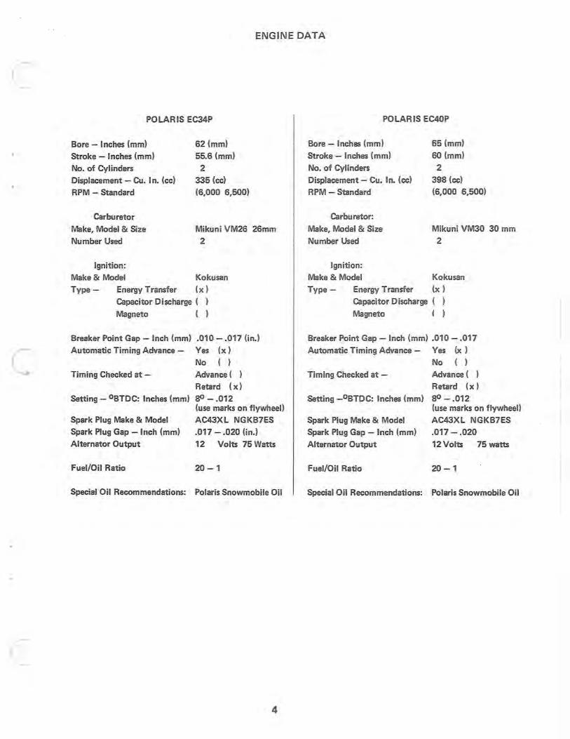
ENGINE DATA
POLARIS EC34P
Bore - Inches (mm)
Stroke - Inches (mm)
No. of Cylinders
Displacement - Cu. In. (cc)
RPM - Standard
Carburetor
Make, Model & Size
Number Used
Ignition:
62 (mm)
55.6 (mm)
2 335 (cc)
(6,000 6,500)
Mikuni VM26 26mm
2
Make & Model Kokusan
Type - Energy Transfer (x)
Capacitor Discharge ( )
Magneto ( )
Breaker Point Gap - Inch (mm) .010 - .017 (in.)
Automatic Timing Advance - Yes (x)
Timing Checked at -
Setting - °BTDC: Inches (mm)
Spark Plug Make & Model
Spark Plug Gap - Inch (mm)
Alternator Output
Fuel/Oil Ratio
Special Oil Recommendations:
No ( )
Advance (
Retard (x)
80 - .012 (use marks on flywheel)
AC43XL NGKB7ES
.017 - .020 (in.)
12 Volts 75 Watts
20 - 1
Polaris Snowmobile Oil
4
POLARIS EC40P
Bore - Inches (mm)
Stroke - Inches (mm)
No. of Cylinders
Displacement - Cu. In. (ee)
RPM - Standard
Carburetor:
Make, Model & Size
Number Used
Ignition:
Make & Model
65 (mm)
60 (mm)
2 398 (cc)
(6,000 6,500)
Mikuni VM30 30 mm
2
Kokusan
Type - Energy Transfer (x)
Capacitor Discharge ( )
Magneto ( )
Breaker Point Gap - Inch (mm) .010 - .017
Automatic Timing Advance - Yes (x)
Timing Checked at -
Setting _ oBTDC: Inches (mm)
Spark Plug Make & Model
Spark Plug Gap - Inch (mm)
Alternator Output
Fuel/Oil Ratio
Special Oil Recommendations:
No ( )
Advance (
Retard (x)
80 - .012 (use marks on flywheel)
AC43XL NGKB7ES
.017 - .020
12 Volts 75 watts
20 - 1
Polaris Snowmobile Oil
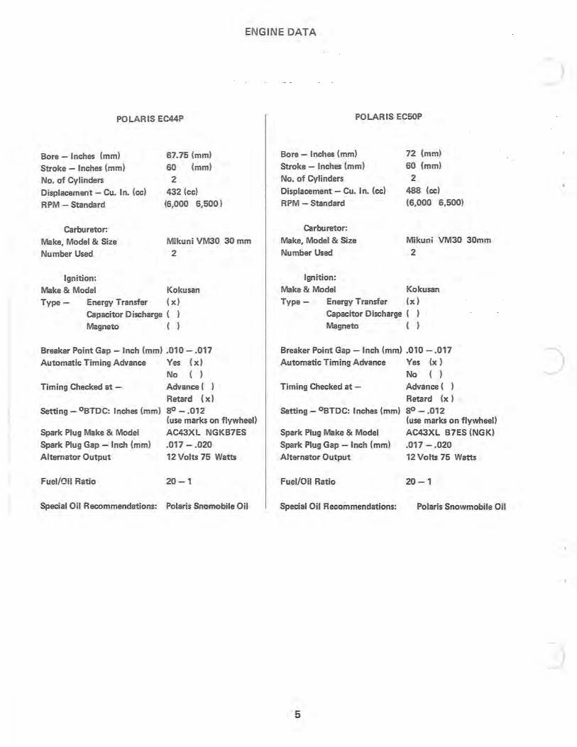
ENGINE DATA
POLARIS EC44P
Bore - Inches (mm)
Stroke - Inches (mm)
No. of Cylinders
Displacement - Cu. In. (cc)
RPM - Standard
Carburetor:
Make, Model & Size
Number Used
Ignition:
67.75 (mm)
60 (mm)
2 432 (cc)
(6,000 6,500 )
Mikuni VM30 30 mm
2
Make & Model Kokusan
Type - Energy Transfer ( x)
Capacitor Discharge ( )
Magneto ( )
Breaker Point Gap - Inch (mm) .010 - .017
Automatic Timing Advance Yes (x)
No ( )
Timing Checked at - Advance (
Retard (x)
Setting - °BTDC: Inches (mm) SO - .012 (use marks on flywheel)
Spark Plug Make & Model AC43XL NGKB7ES
Spark Plug Gap - Inch (mm) .017 - .020
Alternator Output 12 Volts 75 Watts
Fuel/Oil Ratio 20 - 1
Special Oil Recommendations: Polaris Snomobile Oil
POLARIS EC50P
Bore - Inches (mm)
Stroke - Inches (mm)
No. of Cylinders
Displacement - Cu. In. (cc)
RPM - Standard
Carburetor:
Make, Model & Size
Number Used
Ignition:
Make & Model
72 (mm)
60 (mm)
2 488 (cc)
(6,000 6,500)
Mikuni VM30 30mm
2
Kokusan
Type - Energy Transfer (x)
Capacitor Discharge ( )
Magneto ( )
Breaker Point Gap - Inch (mm) .010 - .017
Automatic Timing Advance Yes (x)
No ()
Timing Checked at - Advance (
Retard (x)
Setting - °BTDC: Inches (mm) SO - .012 (use marks on flywheel)
Spark Plug Make & Model AC43XL B7ES (NGK)
Spark Plug Gap - Inch (mm) .017 - .020
Alternator Output 12 Volts 75 Watts
Fuel/Oil Ratio 20 - 1
Special Oil Recommendations: Polaris Snowmobile Oil
5
)
)
)
c
c
c
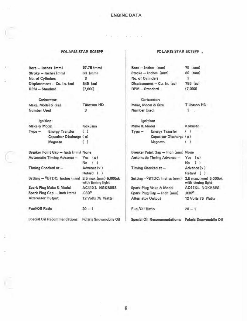
ENGINE DATA
POLARIS STAR EC65PF
Bore - Inches (mm)
Stroke - Inches (mm)
No. of Cylinders
Displacement - Cu. In. (ee)
RPM - Standard
Carburetor:
Make, Model & Size
Number Used
Ignition:
67.75 (mm)
60 (mm)
3 649 (cc)
(7,000)
Tillotson HD
3
Make & Model Kokusan
Type - Energy Transfer ()
Capacitor Discharge ( x)
Magneto ( )
Breaker Point Gap - Inch (mm) None
Automatic Timing Advance - Yes (x)
Timing Checked at -
No ( )
Advance (x )
Retard ( )
Setting - °BTDC: Inches (mm) 3.5 max.(mm) 5,00Ock
Spark Plug Make & Model
Spark Plug Gap - Inch (mm)
with timing light
AC41XL NGKB8ES
.0300
Alternator Output 12 Volts 75 Watts
Fuel/Oil Ratio 20 - 1
Special Oil Recommendations: Polaris Snowmobile Oil
6
POLARIS STAR EC79PF _
Bore - Inches (mm)
Stroke - Inches (mm)
No. of Cylinders
Displacement - Cu. In. (cc)
RPM - Standard
Carburetor:
Make, Model & Size
Number Used
Ignition:
75 (mm)
60 (mm)
3 795 (cc)
(7,000)
Tillotson HD
3
Make & Model Kokusan
Type - Energy Transfer ()
Capacitor Discharge (x)
Magneto ( )
Breaker Point Gap - Inch (mm) None
Automatic Timing Advance - Yes (x)
No ( )
Timing Checked at - Advance (x)
Retard ( )
Setting _oBTDC: Inches (mm) 3.5 max.(mm) 5,000ck with timing light
Spark Plug Make & Model
Spark Plug Gap - Inch (mm)
AC41XL NGKB8ES
.0300
Alternator Output 12 Volts 75 Watts
Fuel/Oil Ratio 20 - 1
Special Oil Recommendations: Polaris Snowmobile Oil
2 0: w I-
~ Q.
W ::::> a 0: o I-o 2 e:( en 2 o le:( U u.. U W Q. en 2 o ~ ~ o u
n
Cyl. Oisp. (CC)
175
294
335
398
436
488
648
795
Engine Year Models Built
EC17P 1969·1970
EC29P 1969·1970
EC35P 1969·1970
EC40P 1969·1970
EC44P 1969·1970
EC50P 1969·1970
EC65P 1969··1970
EC79P 1969·1970
CD
®
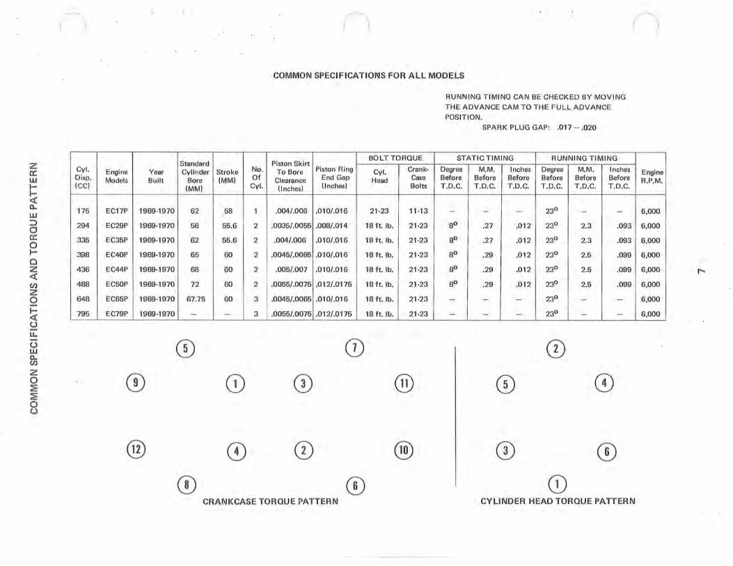
n COMMON SPECIFICATIOI\1S FOR ALL MODELS
BOLT TORQUE Standard Piston Skirt
No. Piston Ring Crank· Cylinder Stroke To Bore Cyl. Bore (MM) Of Clearance End Gap Head Case
(MM) Cyl. (Inches) (Inches) Bolts
62 58 1 .004/.006 .010/.016 21·23 11·13
58 55.6 2 .0035/.0055 .008/.014 18 ft. lb. 21·23
62 55.6 2 .004/.006 .010/.016 18 ft. lb. 21·23
65 60 2 .0045/.0065 .010/.016 18 ft. lb. 21 ·23
68 60 2 .005/.007 .010/.016 18 ft. lb. 21·23
72 60 2 .0055/.0075 .012/.0175 18 ft. lb. 21·23
67.75 60 3 .0045/.0065 .010/.016 18 ft. lb. 21·23
- - 3 .0055/.0075 .012/.0175 18 ft. lb. 21·23
CD 0)
CD CD @
CD CD ® CD CD
CRANKCASETORQUE?ATTERN
RUNNING T IMING CAN BE CHECKED BY MOVING
THE ADVANCE CAM TO THE FUL L ADVANCE
POSIT ION.
SPARK PLUG GAP: .017 - .020
STAT IC TIMING RUNNING TIMING
Degree M.M. Inches Degree M.M. Inches Before Before Before Before Before Before T.O.C. T.O.C. T.O.C. T.O.C. T.O.C. T .O.C.
- - - 230 - -80 .27 .012 230 2.3 .093
80 .27 .012 230 2.3 .093
80 .29 .012 230 2.5 .099
80 .29 .012 230 2.5 .099
80 .29 .012 230 2.5 .099
- - - 230 - -- - - 230 - -
CD CD CD
CD CD CD
CYLINDER HEAD TORQUE PATTER N
I
I I
R.P.M. Engine I
!
6,000 i
6,000
6,000
6,000
6,000
6,000
6,000
6,000
.....
z o le:( ~ a: o u. Z
w ()
> a: w en Cl w en Z w Cl Z o ()
Year
1971
1971 1971 1971 1971 1971
1971 1971
1971
1971 1971
1971 1971 1971 1971
u
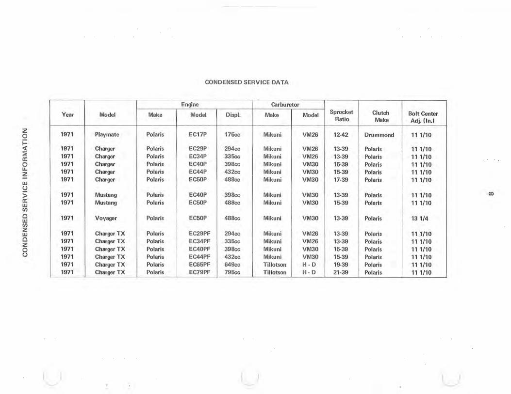
Model Make
Playmate Polaris
Charger Polaris Charger Polaris Charger Polaris Charger Polaris Charger Polaris
Mustang Polaris Mustang Polaris
Voyager Polaris
Charger TX Polaris Charger TX Polaris Charger TX Polaris Charger TX Polaris Charger TX Polaris Charger TX Polaris
CONDENSED SERVICE DATA
Engine Carburetor
Model Displ. Make
EC17P 175cc Mikuni
EC29P 294cc Mikuni EC34P 335cc Mikuni EC40P 398cc Mikuni EC44P 432cc Mikuni EC50P 488cc Mikuni
EC40P 398cc Mikuni EC50P 488cc Mikuni
EC50P 488cc Mikuni
EC29PF 294cc Mikuni EC34PF 335cc Mikuni EC40PF 398cc Mikuni EC44PF 432cc Mikuni EC65PF 649cc Tillotson EC79PF 795cc Tillotson
u
Model Sprocket Clutch Bolt Center Ratio Make Ad j. (I n. )
VM26 12·42 Drummond 11 1/ 10
VM26 13-39 Polaris 11 1/ 10 VM26 13-39 Polaris 11 1/ 10 VM30 15-39 Polaris 11 1/ 10 VM30 15-39 Polaris 11 1/ 10 VM30 17-39 Polaris 11 1/ 10
VM30 13-39 Polaris 11 1/ 10 co VM30 15-39 Polaris 11 1/ 10
VM30 13-39 Polaris 131 /4
VM26 13-39 Polaris 11 1/ 10 VM26 13-39 Polaris 111/ 10 VM30 15-39 Polaris 11 1/ 10 VM30 15-39 Polaris 111/ 10 H-D 19-39 Polaris 11 1/ 10 H-D 21-39 Polaris 11 1/ 10
u

ELECTRICAL SYSTEM INFORMATION
THE WIRE HARNESS
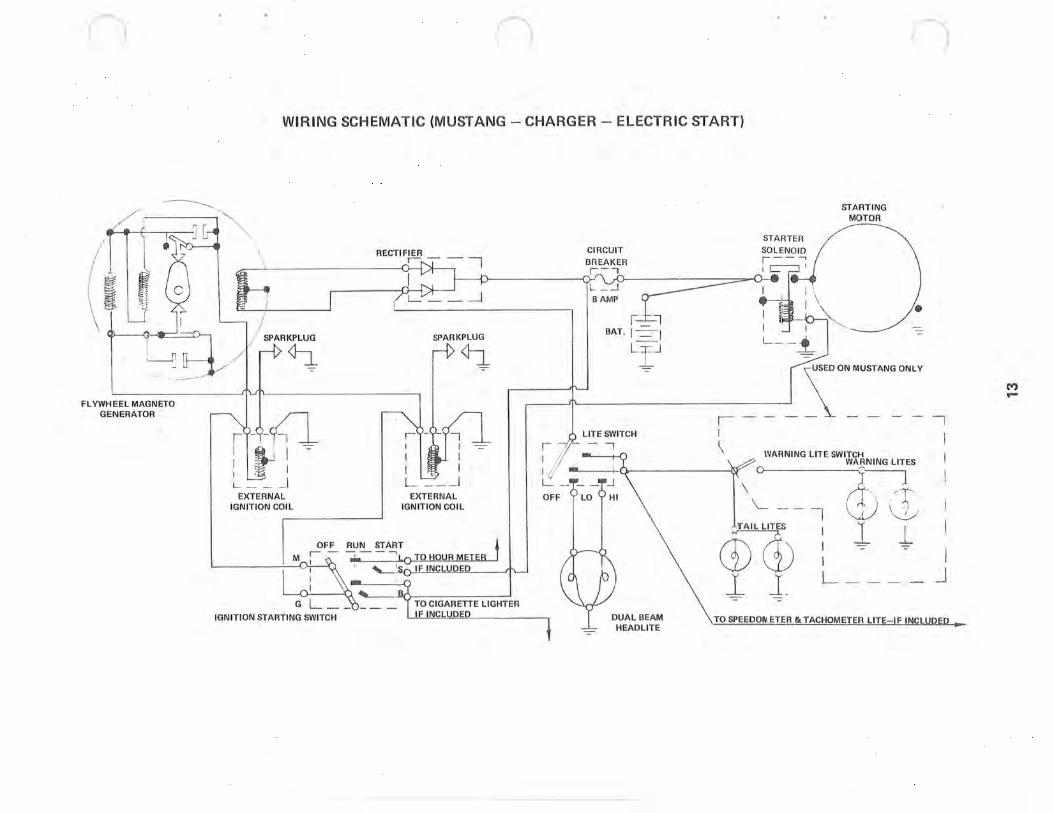
The Mustang and Charger have one standard wiring harness again this year which is designed for either electric or nonelectric start models using any engine . . . The TX models have their own harness, as does the Playmate.
All harnesses are protected by Grayline tubing. This is a high temperature tubing, but it will melt if allowed to touch the exhaust pipes and care should be taken to avoid this.
ELECTRIC START SYSTEMS
Electric start systems may be installed on all engines in the Charger and Mustang. The existing wiring harness is used, adding a circuit breaker, a rectifier, a lead wire, and a starter with solenoid, plus the needed battery cables, battery, and solenoid wire assembly to connect the solenoid to the main harness.
To charge the battery, the alternator's A.C. (alternating current) output must be rectified to D.C. (direct current) . This is accomplished by a pair of diodes mounted in parrallel in a square shaped rectifier. This rectifier is protected by an 8 amp circuit breaker, to protect the alternator coil, should one of these diodes fai l.
There are two alternator systems used this year. A 75 watt alternator system is found on all Chargers, Mustangs, and TX models, and a 35 watt system is on Playmate models. Each alternator coil has the capacity of producing three amperes of current going to the battery. With the lights off, all the current goes to the rectifier, from which it is tapped for lights, with the remaining current going to the battery. The lights will not operate with t he engine not running as they are connected off the alternator circuit, not the battery; hence they cannot discharge the battery. In the electric start system, the battery acts as a voltage regulator.
An 8 amp circuit breaker is included on the instrument panel in the electric start system to protect the wiring harness and eliminate the danger of fire due to a short circuit.
LIGHTING
The lighting system for the Charger and TX consists of a dual beam headlamp and two taillamps. On the Mustang, there is a dual beam headlamp, four taillamps, and two warning light lamps. The Playmate lighting system consists of a single beam headlamp and two taillight lamps.
The warning light on the Mustang is designed to warn a snowmobile driver behind, when the snowmobile in front hits rough going or slows down suddenly. The sensor is an inertia switch mounted in the instrument panel.
All Mustangs and Chargers use a 60 watt headlamp - Polaris Part No. 4030007 or G.E. No. 4454. The Playmate uses a 25 watt head lamp - Polaris Part No. 4030005 or G.E. No. 4568.
NOTE: When the hood is removed, the headlight becomes disconnected and all lighting circuits become open. This prevents excessive voltage from being applied to the instrument and taillights, should the li_hts be turned on when the hood is off.
ACCESSORIES
The electrical system is designed to accept the speedometer, tachometer, and cigafett lighter as standard options. The necessary wiring instructions are included with each option. If additional information is needed, consult the instrument panel wiring diagram or the applicable wiring harness drawing.
For special equipment, such as hourmeters, ammeters, etc., contact the Polaris Service Department.
9
)
)

c
c
c
TROUBLE SHOOTING HINTS (Electrical)
Manual Start Will Not Start 1. Check the ignition switch that it is in the run position. 2. Check auxiliary shut-off switch. 3. Check the fuel supply. 4. Check wiring from the engine to the coil(s), and to the spark plug(s). 5. Check the spark plug(s) . 6. Disconnect the engine connector to eliminate any shorts that may be in the main harness wiring.
Electric Start Will Not Start 1. Check the six items above. 2. If starter doesn't work:
a. Check the wires between the starter solenoid and battery. b. Check the battery cables and battery.
Battery Will Not Charge 1. Check for bad connections. 2. Check alternator output.
Lights Don't Work 1. The engine must be running before the lights will work. 2. Check to see that the headlight harness connector is connected, as th is cuts off all lights to prevent burning
them out from excessive voltage. 3. Check for burned out lamps. 4. Check for loose connections and shorted wires. 5. Disconnect the taillight connector. If the headlight works, this indicates a short in the wiring to the taillight.
10
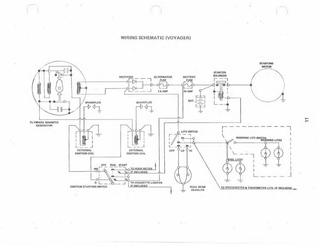
(~ FLYWHEEL MAGNETO
GENERATOR
EXTERNAL IGNITION COIL
IGNITION STARTING SWITCH
WIRING SCHEMATIC (VOYAGER)
EXTERNAL IGN ITION COIL
7.5 AMP
STARTING
STARTER MOTOR
SOLENOID f\ ..h tthl.::l
"AM' l iC-f • 'ATi-i : I \ J LIJ L-i ~~4
I I --------- 1
DUAL BEAM HEADLITE
\
{:'''.~' ~'~'.~ I -=-I L
I I I
1
I 1
I J
TO SPEEDOMETER It TACHOMETER LITE IF INCLUDEP •
.... ....
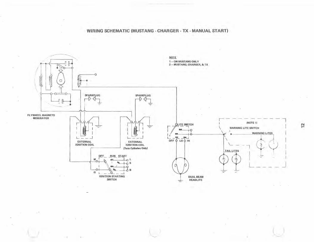
WIRING SCHEMATIC (MUSTANG - CHARG ER - TX - MANUAL START)
-----.--------------~ "./--- , ..... ,
........ _-
FLYWHEEL MAGNETO GENERATOR
SPARKPLUG
rf> ~ -:-
ir~-li -=- ___ J I LJr I L __ -' EXTERNAL
IGNITION CO~~
M
SPARKPLUG
~
EXTERNAL IGN IT ION COIL
(Twin Cylinders Only)
-=-
IGNITION STARTING SWITCH
u u
NQI~
1 - ON MUSTANG ONLY 2 - MUSTANG, CHARGER, & TX
LITE SWITCH
' 7' ''--' I h ' ------' 1/ L -"1"- _.,..J
OFF 0 LO 6 HI
DUAL BEAM HEADLITE
1---- - - -- I I (NOTE 1)
\ I WARNING LITE SWITCH
\ -' WARNING LI T ES I / ....
\1 . \ ( I
\ - - - [ ~( I T.&u~ I I
L (f I I
L _ _ _ _ J
u
N ...
n
('lit t3
\ ~ \~~
i L-,n I _ Li
FLYWHEEL MAGNETO GENERATOR
"- "---
n
WIRING SCHEMATIC (MUSTANG - CHARGER - ELECTR IC START)
"
", \
\ STARTER
RECTIFIER CIRCUIT
STARTING MOTOR
~--L-------------------~~-4 -- --- ~ BREAKER ,... r-,
i /
/ SP~R~
I ~ I L.. .-J
EXTERNAL IGNITION COIL
-:-
IGNITION STARTING SWITCH
SPARKPLUG
~
EXTERNAL IGNITION COIL
~ ::::::=- a---. !lAMP
r --=t::.-l BAT. I - I
• -=
LII - ......--\SED ON MUSTANG ONLY
~ ___ ~~ I __ ~ I -- "I
LITE SWITCH --,
DUAL BEAM HEADLITE
~- --------
I I \ WARN ING LITE o SWITCH
\ L I NG
"1' , ,"i""" I W(£,I dS(l) : l -1- i
l 1 L I .. J
TO SPEEDOI'I.ETER & TACHOMETER LITE-IF INCLUDED ..
(II) ...
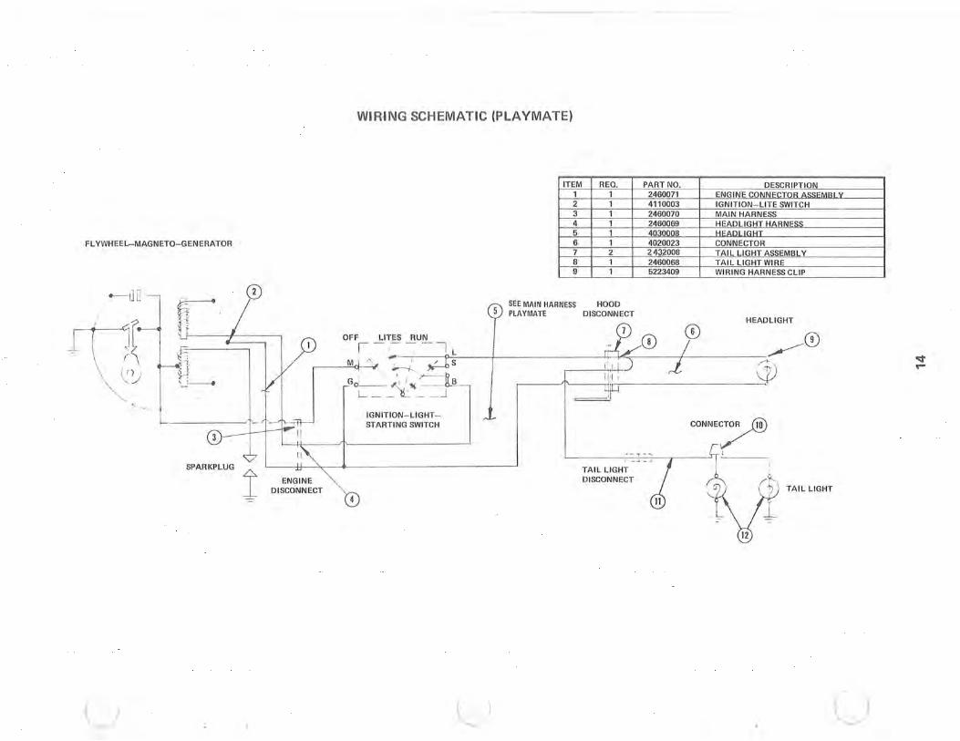
WI RING SCHEMATIC (PLAYMATE)
ITEM 1 2 3 4 5
FLYWHEEL- MAGNETO- GENERATOR 6 7 8 9
"-I] Q-, . CD
L f\1r1f ~ I }D - (, .;' I \ i I) , ;jJ ~,\..j 'L.~
p ~
... ~ ,
IGNITION-LIGHT -STARTING SWITCH
CD SPARKPLUG 1
ENG INE DISCONNECT
B
u u
REO, 1 1 1 1 1 1 2 1 1
I' 1-<
TAIL LIGHT DISCONNECT
PART NO, DESCR IPTION 2460071 ENG INE CONNECTOR ASSEMRI V 4110003 IGNITION-LITE SWITCH 2460070 MAIN HARNESS 2460069 HEADLIGHT HARNESS 4030008 HI'anllf1HT 4020023 CONNECTOR 2. 432008 TAIL LIGHT ASSEMBL Y 2460068 TAIL LIGHT WIRE 5223409 WIRING HARNESS CLIP
HEADLIGHT
/ .~CD <~l ~
o;t ....
CONNE~
,I
TAIL LIG HT
u

TROUBLE SHOOTING
1. Engine fails to start a. ignition switch off
b. out of fuel c. fuel line kinked d. fuel filter clogged e. fuel pump impulse hose cracked or leaking
f. choke on but throttle handle compressed g. chokes stuck open so engine flooded (Mikuni Carb.)
2. No spark a. spark plug fouled b. secondary coil dead or wires disconnected
c. primary coil shorted or dead d. ignition points dirty or pitted e. shorted ignition switch
3. No compression a. crankcase plug is out b. headgasket is blown c. bad rings or piston
4. Engine idles but fails to accelerate a. restricted fuel flow b. clogged main jet
5. Engine runs but fails to reach maximum R.P.M.
a. clogged fuel filter b. track tension (incorrectly sed c. incorrect main jet d. throttle slides not fully open e. chain in chain case too tight f. front hanger on drift skipper in wrong hole location
S. Engine runs but fails to idle a. incorrect air mixture setting b. throttle stop screw incorrectly adjusted c. dirt in pilot jet
7. Engine runs but overloads with fuel a. chokes are not seating (twisted cable) b. fuel pump diaphragm is ruptured (cause by backfire) c. carburetor slides are not synchronized
d. too large main jet e. needle and seat not seating properly f. incorrect float level
8. Engine runs but overheats a. incorrect main jet b. incorrect timing c. incorrect spark plug
9. Burned pistons a. Too hot a spark plug such as BSE. Never use these in Polaris Twin Engines. A loose plug can create a hot running condition. See service Bulletin No. 27. b. Lean carburetor mixture. This can happen from improper adjustment, loose carburetor, restricted fuel line, clogged fuel filter, loose impulse tube, repeated running out of gas, etc. c. Improperly mixed fuel and oil or poor grade of gasoline or oil. Regular grade gasoline should be used. Some two-cycle oil on the market mixes very poorly or with difficulty especially at low temperatures. The oil should be room temperature if possible and mixed vigorously. Mixture ratio should be 20 to 1. d. Overchoking. If engine is overchoked, fuel may accumulate in crankcase and throw air-fuel ratio out of balance resulting in erratic performance. Crankcase should be drained periodically or at any time erratic performance is noticed. Drains are located low on the front of the crankcase for draining purposes. This is especially important whenever starting problems are experienced. e. Incorrect timing of ignition spark. See Service Bulletin No. 27. Check timing whenever piston burning occurs. Correct timing after installing new piston.
15
c
c
c
INSTRUCTION FOR FUEL PUMP (MODEL DF 62 - 24)
1. Summary
Model 62-24 fuel pump is an air pressure type pump. In a 2-cycle engine, the pressure in the crank chamber changes as shown in fig. 1 by the up and down motions of the piston. The waves of pressure vary according to the rpms and the opening of the carburetor throttle valve. In either case, the wave has enough amplitude to make the fuel pump function. Our Model OF 62- 24 makes the diaphragm move up and down by the pressure in the crank chamber which creates the pumping function.
2. Functions and constructions. (Fig. 2)
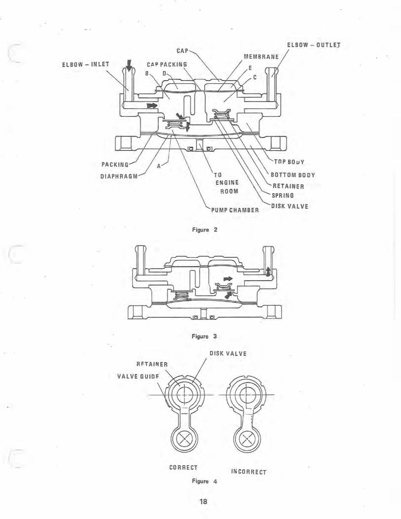
Model 62- 24 fuel pump is constructed with functional parts such as the bottom body, the top body, the cap, the diaphragm, the inlet valve, the outlet valve, the membrane etc., and is furnished with the wave motion pressure chamber A, the pump chamber, the fuel chambers Band C, the air chambers 0 and E.
2-1. Intake action (Fig. 2)
The pressure in the crank chamber is led to chamber A through the passage of the wave motion in the bottom body.
When the pressure in the crank chamber becomes negative, the diaphragm moves in the way shown in fig. 2, and the capacity of the pump chamber expands. At that moment, the inlet valve opens and the outlet valve closes, and the fuel is drawn into the pump chamber from fuel chamber B through the elbow on the side of intake.
2-2. Discharge action.(Fig. 3)
When the pressure in the crank chamber becomes positive, the diaphragm moves in the way shown in fig. 3, and the capacity of the chamber reduces. At that moment, the inlet valve closes and the outlet valve opens, and the fuel in the pump chamber is delivered by pressure from the elbow on the discharge side to the float chamber of the carburetor through fuel chamber C.
As mentioned above, intake actions and discharge actions are repeated alternately to make the pump function.
2- 3. Actions of principal functional parts.
(a) Inlet valve and outlet valve. The inlet valve opens on the intake stroke of the diaphragm and closes on the discharge stroke. Therefore, the outlet valve closes on the intake stroke and opens under the positive pressure, thus operating to prevent the backward flow of fuel. (b) Diaphragm. The diaphragm functions to increase or decrease the capacity of the pump chamber by its up and down motions. (c) Fuel chambers Band C, air chambers 0 and E, and membrane. Basically, pumping action is possible without fuel chambers Band C, the air chambers 0 and E, and the membrane provided. However, under such conditions there are some troubles such as:
(1) The flow of fuel tends to be intermittent, and the pumping efficiency drops. (2) Bubbles tend to occur in the fuel pipes. (3) The fuel level is not stable due to large pulsations of fuel pressure on the needle valve in the carburetor float chamber.
The fuel chambers Band C, the air chambers 0 and E, and the membrane perform to keep the flow of fuel as constant as possible, to keep the amplitude of the fuel pressure as small as possible on the needle valve of the carburetor float chamber, and to make the fuel level stable.
3. Disassembly and reassembly.
In disassembly and reassembly, care should be used to handle all parts with proper tools so that they will not be scratched or battered. When disassembled, all parts should be washed out in gasoline or kerosene, and blown dry with an air·
16
compressor.
3- 1. Instructions on disassembly.
(a) Whenever disassembled, the cap gasket, the membrane, the diaphragm, and the gasket should be replaced with new ones.
(b) Care should be used not to reassemble the cap gasket in a wrong order. (The membrane should be reassembled on the side of the top body.)
(c) As shown in fig. 4, reassemble the valve retainer at the center of the guide. Care should be used as to the valve retainer and set screws. A countersunk screw is used for the valve retainer which has a countersink on the side of the inlet, and a round screw is used for the valve retainer which has no countersink on the side of the outlet. Particularly, extreme care should be used to have the top of the countersunk screw on the side of inlet free from scratches for fear that they should damage the diaphragm.
(d) Be careful not to make mistakes in the order of reassembly of the diaphragm and the gasket. (Reassemble the gasket on the side of the bottom body). These parts should be replaced with new ones whenever reassembled.
(e) Pay particular attention to the joints which must be sealed tight. If they are scratched or battered, they will tend to cause leakage of fuel or air.
3-2. Inspection after reassembly.
Dip the pump in gasoline or kerosene and check that there are no bubbles at each joint by an air-tight test in which the elbow on the discharge side is closed with a finger and compressed air of 11 Ibs. is blown from the elbow on the intake side.
4. Causes of trouble and corrections.
Troubles of this pump show themselves in a reduction of discharge volume due to the fall of both discharge and intake pressure.
Causes of trouble
1.
2.
3.
4.
5.
6. 7.
LOQse attachment of the inlet valve and the outlet valve, or the damage or wear of the valve spring. Damage of the diaphragm or the membrane.
Leak of wave motion pressure.
Leak of fuel due to poor pieJing.
Other leaks.
Presence of dust and impurities. Clog of the filter.
17
Corrections
1.
2.
3.
4.
5.
6. 7.
Replacement by the pump assy.
Replacement with a new one. (When reassembled, the gasket and the gasket cap also should be replaced at the same time.) Check all joints of passage of the wave motion from the crank chamber to the bottom body. Check the fuel pipe and the elbow on the sides of intake and discharge. Make the air-tight test according to paragraph 3-2, and: (a) If the leak is due to the joint of the top body and the bottom body, replace the diaphragm and the gasket with new ones. (b) If the leak is due to the joint of the top body and the cap, replace the membrane and the cap gasket with new ones. Check the inlet valve and the outlet valve. Clean at regular interoals.
)
c ElBOW - IN LET
OIAPHRAGM
c
VALVE GUIDE
c
ELBOW - OUTlEJ CAP
MEMBRANE
ENGINE
ROOM
PUMP CHAMBER
Figure 2
Figure 3
DISK VALVE
CORRECT INCORRECT
Figure 4
18
TOPBOuY
INSTRUCTION FOR CARBURETOR (MODEL VM - 30)
This manual has been prepared for those who engage in maintenance and repair of Model VM-30 carburetor installed to Polaris Model EC-40, 44, 50 snowmobile so that they may work with proper understanding and knowledge of its
constructions and functions.
1. Constructions and functions.
Model VM-30 carburetor has varying constructions depending upon varying driving conditions, and is constructed with the float system, the pilot system, the main system, and the starter system (initial starting device!.
1-1. Float system (Fig. 11
The float system is designed to maintain a constant height of gasoline during operation.
When the fuel flowing from the fuel pump into the float chamber through the needle valve reaches the constant fuel level, the float rises. When the buoyancy of the float and the fuel pressure of the fuel pump balance, the needle valve sticks fast to the needle seat, preventing further delivery of gasoline, thereby holding the standard level of gasoline.
The standard level of gasoline is set at below 30 mlm ± 1 from the center of the main bore.
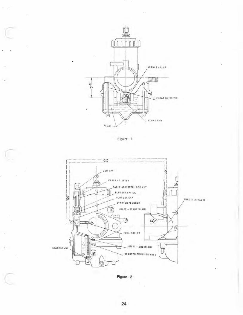
1- 2. Starter system - Choke system (Fig. 2)
The starter system is designed to make the engine start quickly in cold weather. It is constructed with functional parts such as a starter jet, a starter emulsion tube, and a starter plunger etc.
When the engine starts with the throttle valve closed and the starter plunger wide open, the intake negative pressure of the engine works on the fuel nozzle. By this negative pressure the fuel is measured by the starter jet, mixed with air in the starter emulsion tube, absorbed into the plunger chamber, mixed again with air from the starter air inlet, made the most suitable concentration of fuel-air mixture for initial starting, and delivered to the engine through the fuel nozzle.
In this starter system, you can be sure of initial starting without any skill of operation, since both fuel and air are measured and the constant fuel-air mixture ratio is always secured.
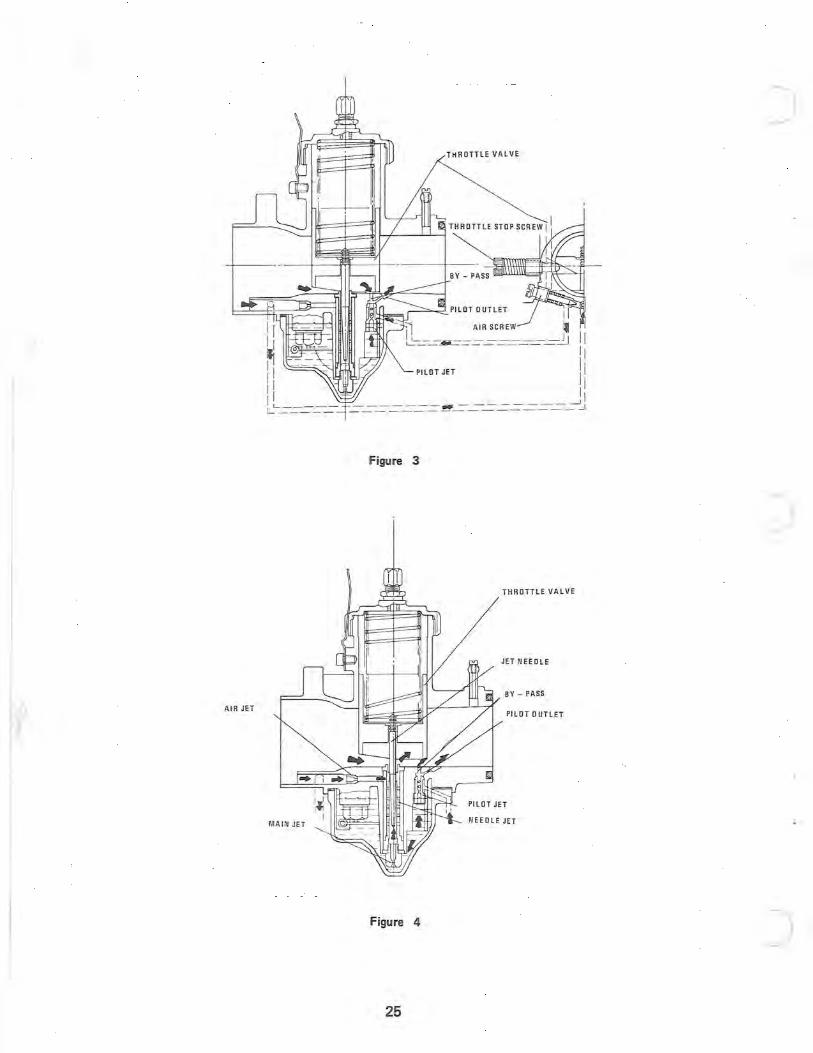
1-3. Pilot system (Fig. 3 & 4)
The pilot system is designed to deliver gasoline during idling and low-speed driving.
Fuel for idling is measured by the pilot-jet, mixed with the air regulated with the air-screw, mixed again with the air from the by-pass, and delivered to the engine through the pilot outlet. The concentration of fuel-air mixture for idling is determined by the air screw. When the air screw is closed the amount of air is reduced and the fuel -air mixture is enriched. When the air screw is opened the amount of air increases and the fuel -air mixture is lean.
When the throttle valve opens slightly during low-speed driving, gasoline injects through the by-pass in addition to the
fuel-air mixture from the pilot outlet to secure smooth operation of the engine. When the throttle valve opens wider, approximately above 1/8 of the diameter of the main bore, gasoline injects through the needle jet. The adjustment of the time and the amount of injection from the needle jet is chiefly performed by the cutaway furnished on the side of the air cleaner of the throttle valve.
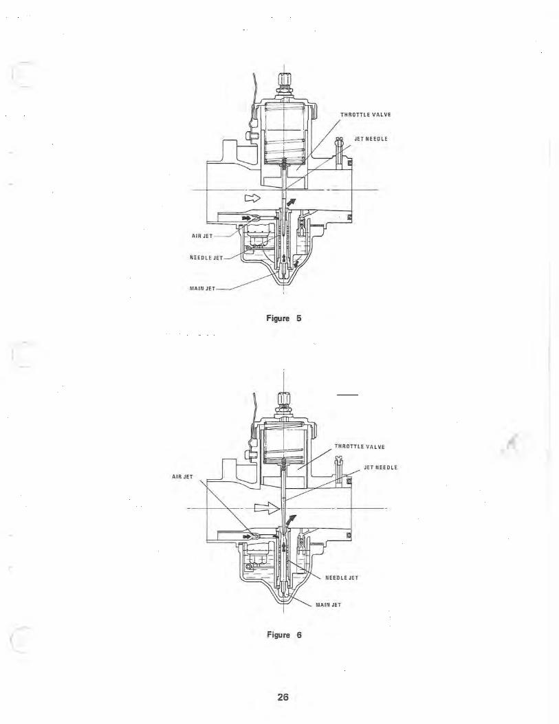
1-4. Main system (Fig. 5 & 6)
The main system is designed for delivering fuel between low·speed driving and high·speed driving.
The fuel during the low·speed driving is delivered, as shown in fig. 4, from the pilot system and the main system. During intermediate-speed driving (the opening of the throttle valve is above 1/4), the fuel is largely delivered from the main system. The fuel during intermediate-speed driving flows into the needle jet through the main jet and mixes with the air measured by the air-jet to make a fine spray of fuel-air mixture of good quality.
19 •
c
c
c
The point of the jet needle is tapered to adjust the flow of fuel-air mixture in accordance with the opening of the throttle valve. During high-speed driving (the opening of the throttle valve is above 3/4) the fuel is measured by the main jet and mixed with the air measured by the air jet to make a fine spray of fuel-air mixture of good quality for delivery to the engine.
2. Adjustments.
When the engine has dual carburetors, it is the prerequisite for full engine performance to maintain the equal operation of each carburetor. The following items should be followed cautiously and accurately.
2- 1. Adjustment of choke wire.
Make adjustment with some degree of play for the starter wire so that the starter plunger of each carburetor may not rise when fully closed. However, the play must be adjusted without excess and deficiency, since the concentration of the fuel-air mixture during the initial starting will get confused if the degree of play is so excessive that the starter plunger cannot be opened to its full width.
2- 2. Adjustment of throttle wire.
With your eye or plug gauge, adjust the opening of each throttle valve from the side of the air cleaner with the throttle wire attached and the throttle open. With your eye, you can adjust accurately by matching the corner of the cutaway of the throttle valve with the upper surface of the main bore. After adjustment, be sure to fasten the cable adjuster lock nuts as well as the starter wire.
2- 3. Adjustment of idling and synchronization.
(a) Set the air screw of each carburetor at the standard return number and then fasten the throttle stop screw of each carburetor evenly, setting the number at about 1,000 rpm which is a little higher than normal idling speed.
(b) Warm up the engine completely.
(c) Find out and set the position where the number of rpms of the engine becomes maximum by opening or clos-ing the air screws one by one about 1/2 each time. In this case, be sure to use a tachometer.
(d) Return each screw of the throttle valve evenly and set at the normal number of rotations of idling.
(e) Find out and set the position once more where engine rotation becomes maximum by opening or closing the air screws one by one about 1/16 each time.
(f) If the number of rotations has changed in the adjustment mentioned in paragraph (e), set once more at the normal number of rotations of idling by means of each throttle stop screw.
(g) Remove the plug cap of each cylinder and check whether the down percentage in the number of rotations of the engine is constant or not at that time. If not, return the throttle stop screw on the side where the down percentage is larger and adjust so as to make the down percentage constant.
(h) In the last step, operate for 5- 10 minutes by idling. If the rotations of the engine are normal during that time, the adjustment is complete. If abnormal, remove the ignition plug and check the condition of combustion. If the combustion seems to be somewhat over, return the air screw, and if somewhat under, fasten the air screw.
2-4. Adjustment in accordance to the altitude and the temperature.
The density of the air varies according to the altitude and the temperature. It is necessary that the delivery of the fuel in the carburetor should be changed according to the change of the density of the air.
During idling and low-speed driving, make adjustment according to the procedures mentioned in paragraph 2-3.
20
During intermediate and high speed driving, make adjustment by means of the main jet according to the following table.
Jetting 0-5000 ft. 5000- 10,000 ft. Inlet Needle & Seat 294 240-220 220-200 1.2 335 250-230 230-210 1.2 398 270-250 250-230 1.5 436 290-270 270-250 1.5 488 310- 280 280- 260 1.5
3. How to handle. Initial starting.
For initial starting in cold weather, start the engine with the choke full open. On this occasion, it is necessary to be careful not to open the throttle valve. If you open the throttle valve, the negative pressure working for the injection of the fuel for the starter drops and the intake of the fuel becomes weak. When the engine has started, warm up the en·
gine with the choke engaged. After warm up, return choke to normal position. When starting an engine that is already warm, activitate throttle slightly (about 1/3).
4. Overhaul service.
As you may have understood by the preceding explanations, a carburetor has little mechanical functions, and troubles
are mostly due to the wear of parts and the clog by dirt and dust. In overhaul service, use gasoline for washing out and blow dry with an air-compressor. Observe the following instructions.
4-1. Starter system.
(a) The starter jet is driven into the float chamber body. Jets should never be cleaned by drills or wire.
(b) Be careful in handling the starter plunger, since scratches on the circumference cause malfunctioning and
scratches on the base prevent a tight seal which may cause a fuel leak while driving.
(c) Since a damaged or worn rubber cap of the starter allows the invasion of water from outside, replace it with a new one.
4- 2. Pilot system.
(a) Be sure to use proper tools for overhauling the pilot jet, and be careful not to make scratches. Wash out in gas-oline and blow dry with an air-compressor.
(b) If the taper of the air screw is disfigured or worn, replace it with a new one.
(c) When the pilot jet and the air screw are disassembled, carefully clean the passages on the side of the body (the . pilot outlet and the by-pass etc.).
4-3. Main system.
(a) Be sure to use proper tools for disassembling the main jet and the needle jet, and be careful not to make scratches when reassembling. (Excessive tightening is a cause of disfigure or damage.)
4- 4. Float system.
(a) Be careful not to bend the float guide pin in handling. If bent, the pin causes malfunctioning of the float.
21
)

c
c
c
(b) The needle valve can be disassembled into the valve seat and the float valve. When it is replaced because of wear or scratches, use the complete needle valve assembly.
(c) Every time overhaul is performed, replace the float chamber packing with a new one.
5. Disorder and adjustment.
A carburetor is a vessel with a lot of precision jets and a constant fuel level. It is so constructed that when the negative pressure of intake of the engine functions, proper concentration of fuel-air mixture is obtained for the operation of the engine.
Accordingly, except for the mechanical disorders most carburetor problems are caused by an abnormal concentration of the fuel-air mixture due to accumulated dirt and dust and wear of parts.
Disorders of the engine due to an abnormal fuel-air mixture are as follows:
When the fuel-air mixture is too rich: (1) The rotations sound overwrapped and intermittent. (2) When the choke is opened, the condition becomes worse. (3) When the engine is warmed up, the condition becomes worse. (4) When the air cleaner is removed, the condition becomes better. (5) The ignition plug becomes dark and dusty, (6) Exhaust gas is rich.
When the fuel-air mixture is too lean: (1) The engine is over-heated. (2) When the choke is opened, the condition becomes better. (3) Acceleration is poor. (4) The ignition plug is burnt. (5) Rotations are irregular. (6) Exhaust gas is lean.
Our carburetor is so constructed that the parts to adjust vary according to the degree of throttle opening. After having checked whether the cause of disorder is due to an over-rich mixture or to an over-lean mixture, confirm what parts must be adjusted for a specific throttle opening.
The relation between the degree of the opening of the throttle valve and the functional systems and the parts to adjust is as follows:
Throttle valve Degree of opening 0-1/8 1/8 - 1/4 1/4-3/4 3/4 - Full open Fu nctional system Pilot system Pilot system Main system Main system
Main system Parts to adjust Air screw Throttle valve Jet Needle Main jet
Air screw
When the condition of disorder and the degree of opening have been confirmed, first check and clean the functional ·systems and then adjust the parts in question.
5- 1. Degree of opening: 0 - 1/8, air screw.
When the opening is closed, the amount of air reduces and the fuel-air mixture becomes rich.
When the opening is opened, the amount of air increases and the fuel-air mixture becomes lean.
5- 2. Degree of opening: 1/8 - 1/4, air screw, throttle valve.
When the cutaway of the throttle valve is made larger, the negative pressure which works on the needle jet reduces, and
22
the fuel-air mixture becomes lean.
When the cutaway of the throttle valve is made smaller, the negative pressure which works on the needle jet becomes rich. The cutaways are prepared at intervals of 0.5 m/m alternately.
(Note) The adjustment of the opening can be made either by the throttle valve or the air screw. However, so far as the idling is not in disorder, make adjustment by the air screw.
5- 3. The degree of opening: 1/4 - 3/4, jet needle.
The jet needle has 5 levels of groove. When the grip goes upward (2nd & 1st levels) the space between the jet needle and the needle jet becomes smaller and the fuel-air mixture becomes lean.
When the grip goes downward (4th & 5th levels), the space between the jet needle and the needle jet becomes larger and the fuel-air mixture becomes rich.
5-4. The degree of the opening: 3/4 - full open, main jet.
When the larger number is used, the fuel-air mixture becomes rich. When the smaller number is used, the fuel-air mixture becomes lean.
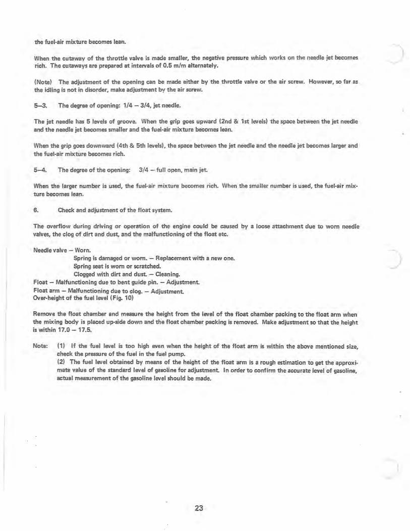
6. Check and adjustment of the float system.
The overflow during driving or operation of the engine could be caused by a loose attachment due to worn needle valves, the clog of dirt and dust, and the malfunctioning of the float etc.
Needle valve - Worn. Spring is damaged or worn. - Replacement with a new one. Spring seat is worn or scratched. Clogged with dirt and dust. - Cleaning.
Float - Malfunctioning due to bent guide pin. - Adjustment. Float arm - Malfunctioning due to clog. - Adjustment. Over-height of the fuel level (Fig. 10)
Remove the float chamber and measure the height from the level of the float chamber packing to the float arm when the mixing body is placed up-side down and the float chamber packing is removed. Make adjustment so that the height is within 17.0 - 17.5.
Note: (1) If the fuel level is too high even when the height of the float arm is within the above mentioned size, check the pressure of the fuel in the fuel pump. (2) The fuel level obtained by means of the height of the float arm is a rough estimation to get the approximate value of the standard level of gasoline for adjustment. In order to confirm the accurate level of gasoline, actual measurement of the gasoline level should be made.
23
)
)
c
c
c
FLOAT GU ID E PIN
FLOAT AR~.~
FLOAT
Figure 1
----- - ---- ----- --- , I-~--=-- -----~ ------------ -1 1 I I 1 I
I I GUM CAP I~
I I I I 1 II CABLE ADJUSTER I II I 1 CABLE ADJUSTER LOCK NUT 1~L-_---1 I I PLUNGER SPR I NG
~I 1 I I I I I 1 I IL
STARTER JET
PLUN GER CAP
STARTER PLUNGE R
INLET - STARTER AIR
INLET - BREEO A I R
STARTER EMULSION TUBE
Figure 2
24
THROTTlE VALVE
) THROTTlE VALVE
H '-------L.J'--; THROTTLE STOP SCREW I:
II
PILOT JET
Figure 3
)
THROTTlE VAL V E
JET NEEOLE
BY - PASS
AIR JET PILOT 0 UTlET
Figure 4 J 25
c THROTTLE VALVE
JET NEEDLE
A IR JET
NEEDLE JET
MAIN JET
Figure 5
c
THROTTLE VALVE
JET NEEDLE
AIR JET
NEEDLE JET
MAIN JET
c Figure 6
26
INSTRUCTION FOR POLARIS ENGINES
The Polaris Star Engines series was designed to be light weight, easy to start, quick to accelerate, dependable, and long lasting. This manual is intended to help you get full efficiency from your engine.
1. Star Engine Features
1) Simple construction, trouble-free operation. 2) Manipulation and adjustment has been reduced to a minimum. 3) Excelling in durability, withstanding long hours of severe operating conditions. 4) Light, compact and high power output. 5) Vertical 2-cylinder alternately firing type, makes vibration very slight. 6) A 2-cycle engine with the lubrication oil mixed in the fuel, no complicated lubrication system is required,
resulting in a very compact engine. 7) Two float type carburetors assure that the fuel supply to the cylinder is exact and positive. No cumbersome
fuel supply adjustment is required.
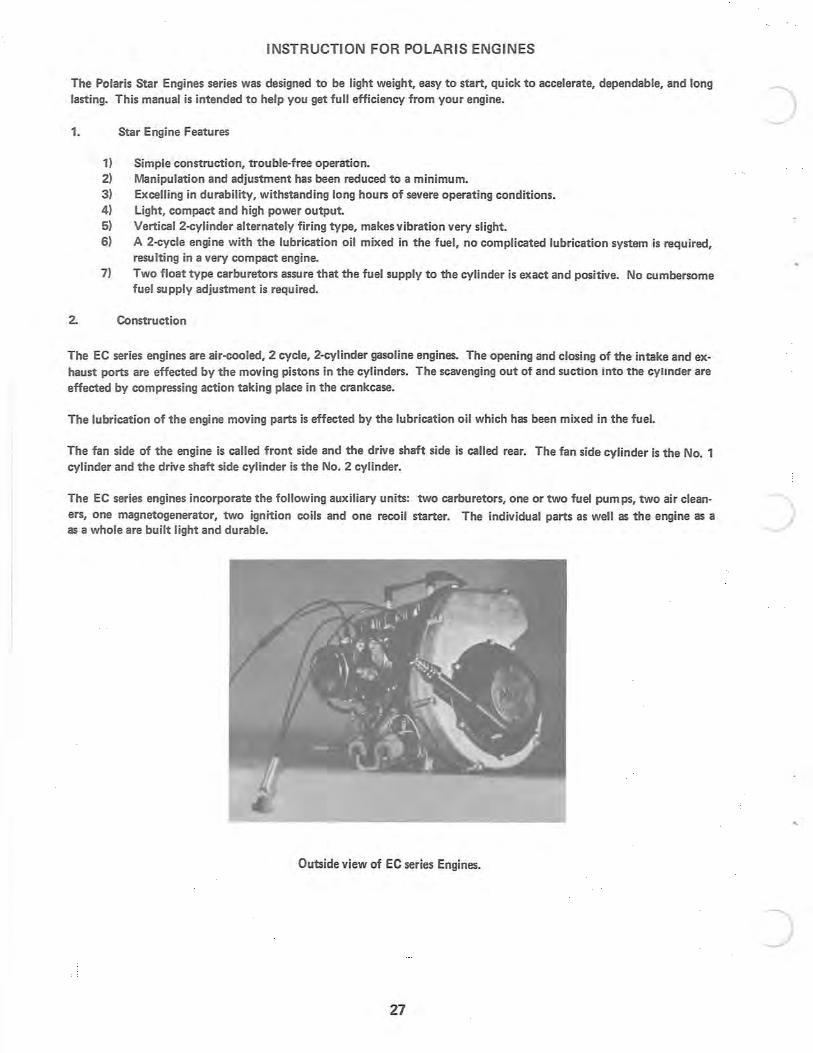
2. Construction
The EC series engines are air-cooled, 2 cycle, 2-cylinder gasoline engines. The opening and closing of the intake and exhaust ports are effected by the moving pistons in the cylinders. The scavenging out of and suction into the cylinder are effected by compressing action taking place in the crankcase.
The lubrication of the engine moving parts is effected by the lubrication oil which has been mixed in the fuel.
The fan side of the engine is called front side and the drive shaft side is called rear. The fan side cylinder is the No. 1 cylinder and the drive shaft side cylinder is the No.2 cylinder.
)
The EC series engines incorporate the following auxiliary units: two carburetors, one or two fuel pumps, two air clean- ) ers, one magnetogenerator, two ignition coils and one recoil starter. The individual parts as well as the engine as a as a whole are built light and durable.
Outside view of EC series Engines.
J 27
c
c
c
3. Cautions
3-1. Crankcase and Relating Parts
a) The crankcase is an aluminum alloy casting consisting of two halves, the upper and lower halves, fastened by 10 mm screws and 8 mm screws. The 10 mm screws should be tightened to 3.1·1.7 kg-m (22.4·26.8 ft· lb) torgue, while the 8 mm screws should be tightened to 2.3·2.7 kg·m (16.6 · 19.5 ft. - Ib.) . Be sure to tighten these screws to the correct torque values when re-assembling the engine.
b) The bore in the crankcase and some other parts have been machined at our factory after the upper and the lower casting halves have been clamped together. Never assemble two odd halves into one crankcase.
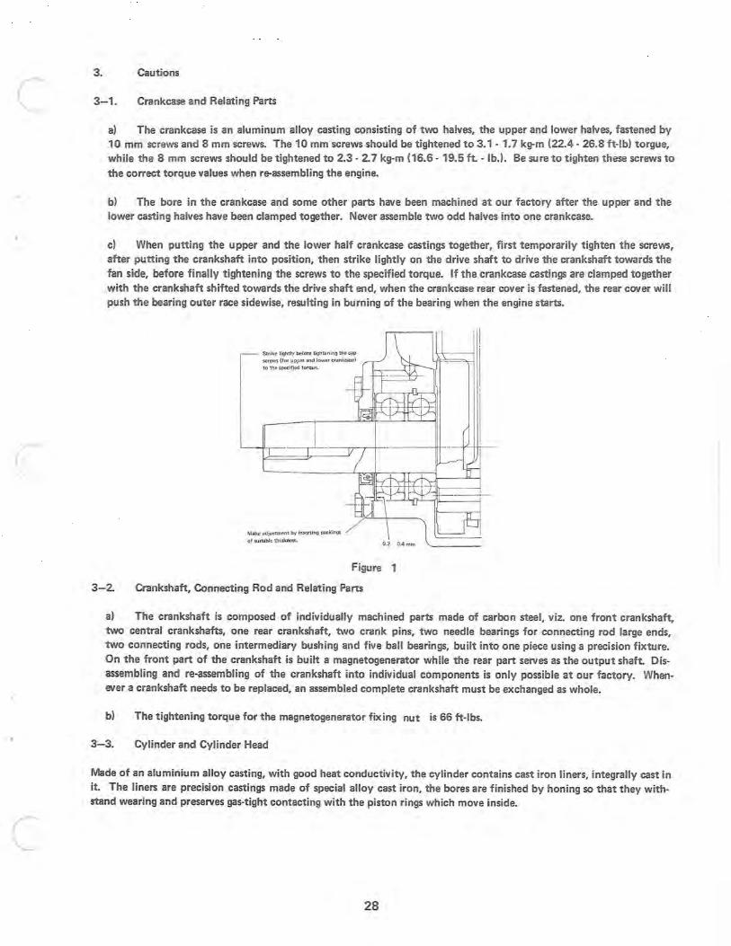
c) When putting the upper and the lower half crankcase castings together, first temporarily tighten the screws, after putting the crankshaft into position, then strike lightly on the drive shaft to drive the crankshaft towards the fan side, before finally tightening the screws to the specified torque. If the crankcase castings are clamped together with the crankshaft shifted towards the drive shaft end, when the crankcase rear cover is fastened, the rear cover will push the bearing outer race sidewise, resulting in burning of the bearing when the engine starts.
Strike lightly before tightening the cap screws (for upper and lower crankcase) to the specified torque.
Make adjustment by inserting packings
of suitable thickness.
Figure 1
3- 2. Crankshaft, Connecting Rod and Relating Pans
a) The crankshaft is composed of individually machined parts made of carbon steel, viz. one front crankshaft, two central crankshafts, one rear crankshaft, two crank pins, two needle bearings for connecting rod large ends, two connecting rods, one intermediary bushing and five ball bearings, built into one piece using a precision fixture. On the front part of the crankshaft is built a magnetogenerator while the rear part serves as the output shaft. Disassembling and re-assembling of the crankshaft into individual components is only possible at our factory. Whenever a crankshaft needs to be replaced, an assembled complete crankshaft must be exchanged as whole.
b) The tightening torque for the magnetogenerator fixing nut is 66 ft-Ibs.
3-3. Cylinder and Cylinder Head
Made of an aluminium alloy casting, with good heat conductivity, the cylinder contains cast iron liners, integrally cast in it. The liners are precision castings made of special alloy cast iron, the bores are finished by honing so that they withstand wearing and preserves gas-tight contacting with the piston rings which move inside.
28
a) Whenever the cylinder is to be disassembled and re-assembled, the cylinder mounting packing must also be re-placed. Tighten the four cylinder mounting screws to 3.1 - 3.7 kg-m (22.4 - 26.8 ft.-Ibl.
b) The cylinder head is made of an aluminum alloy casting, designed to have good cooling characteristics. The combustion chamber is shaped specially so that knocking is minimized and high output power is obtained. Whenever the cylinder head is disassembled, remove carbon deposit from the inside. Tighten the six tightening screws to 2.3 - 2.7 kg-m (16.6 - 19.5 ft-Ib).
3- 4. Piston and Piston Ring
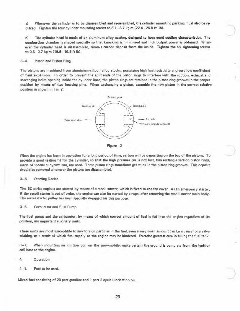
The pistons are machined from aluminium-silicon alloy stocks, possessing high heat resistivity and very low coefficient of heat expansion. In order to prevent the split ends of the piston rings to interfere with the suction, exhaust and scavenging holes opening inside the cylinder bore, the piston rings are retained in the piston ring grooves in the proper position by means of two locating pins. When exchanging a piston, assemble the new piston in the correct relative position as shown in Fig. 2.
Ex hau st port
locating pin ,.--- -.. ........
/' " locating pin
Drive shaft side -- ~ Fanside
"F" mark (stands for front)
Figure 2
When the engine has been in operation for a long period of time, carbon will be depositing on the top of the pistons. To provide a good sealing fit for the cylinder, so that the high pressure gas is not lost, two rectangle section piston rings, made of special alloycast iron, are used. These piston rings sometimes get stuck in the piston ring grooves. This deposit should be removed whenever the pistons are disassembled.
3-5. Starting Device
The EC series engines are started by means of a recoil starter, which is fixed to the fan cover. As an emergency starter, if the recoil starter is out of order, the engine can also be started by a rope, after removing the recoil-starter main body. The recoil starter pu~ley has been specially designed for this purpose.
3- 6. Carburetor and Fuel Pump
The . fuel pump and the carburetor, by means of which correct amount of fuel is fed into the engine regardless of its pOSition, are important auxiliary units.
These units are most susceptible to any foreign particles in the fuel, even a very small amount can be a cause for a valve sticking, as a result of which fuel supply to the engine may be hindered. Exercise greatest care in filling the fuel tank.
3- 7. When mounting an ignition coil on the snowmobile, make certain the ground is complete from the ignition coil base to the engine.
4. Operation
4-1. Fuel to be used.
Mixed fuel consisting of 20 part gasoline and 1 part 2 cycle lubrication oil.
29
)
J

c
c
c
4-2. Starting
Before starting the engine, close the throttle completely and pull the choke control completely out. When air-fuel mixture is too rich, push back the choke control partly.
a) Recoil Starting Pull the rope forcefully, after confirming the position where the cylinder compression starts.
b) Electric Starting 1. If the engine fails to start at the first attempt, repeat several times. (Engage the starter each time, only after the engine has completely stopped. 2. Never engage the starter while the engine is still rotating.
4- 3. Warming up
After starting the motor, idle the engine for 2 or 3 minutes, with the choke partially pulled out. Push back the choke control gradually as the engine gets warm. Never run the engine at high speed; without load the moving parts may lose lubrication and burn out.
4- 4. Stopping Engine
When stopping the engine, allow it to idle down before turning switch off.
4- 5. The electrode gap in the spark plug is .012 - .017 inch.
4- 6. Breaker points gap should be adjusted to .012 - .017 inch.
30
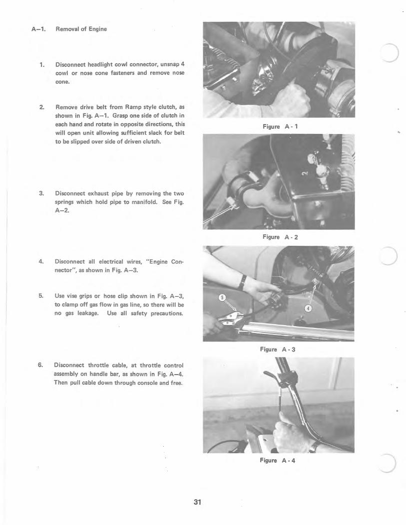
A-1. Removal of Engine
1. Disconnect headlight cowl connector, unsnap 4 cowl or nose cone fasteners and remove nose
cone.
2. Remove drive belt from Ramp style clutch, as shown in Fig. A-1. Grasp one side of clutch in each hand and rotate in opposite directions, this will open unit allowing sufficient slack for belt
to be slipped over side of driven clutch.
3. Disconnect exhaust pipe by removing the two springs which hold pipe to manifold. See Fig. A-2.
4. Disconnect all electrical wires, "Engine Connector", as shown in Fig. A-3.
5. Use vise grips or hose clip shown in Fig. A- 3,
to clamp off gas flow in gas line, so there will be no gas leakage. Use all safety precautions.
6. Disconnect throttle cable, at throttle control
assembly on handle bar, as shown in Fig. A- 4. Then pull cable down through console and free.
)
Figure A- 1 ..
Figure A- 2
)
Figure A- 3
Figure A - 4 J 31
c
c
c
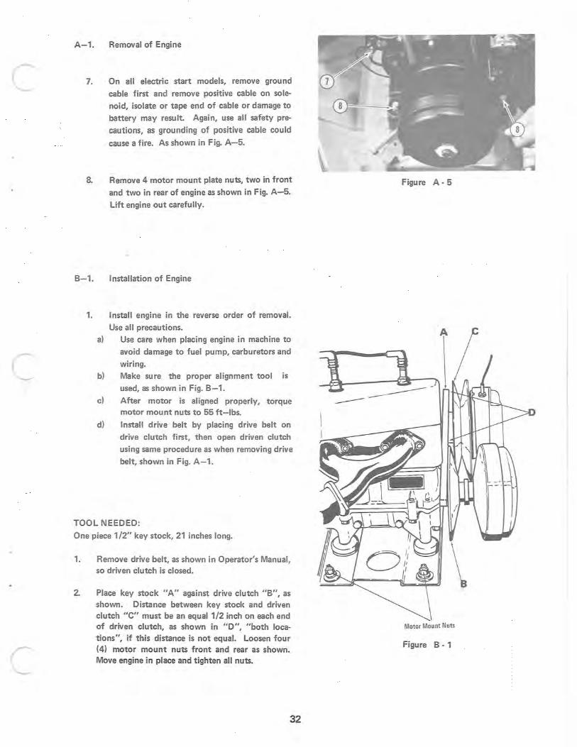
A-1. Removal of Engine
7.
8.
On all electric start models, remove ground cable first and remove positive cable on solenoid, isolate or tape end of cable or damage to battery may result. Again, use all safety pre
cautions, as grounding of positive cable could
cause a fire. As shown in Fig. A- 5.
Remove 4 motor mount plate nuts, two in front
and two in rear of engine as shown in Fig. A-5.
Lift engine out carefully.
B-1. Installation of Engine
1. Install engine in the reverse order of removal.
Use all precautions. a) Use care when placing engine in machine to
avoid damage to fuel pump, carb!Jretors and wiring.
b) Make sure the proper alignment tool is used, as shown in Fig. B-1.
c) After motor is aligned properly, torque motor mount nuts to 55 ft- Ibs.
d) Install drive belt by placing drive belt on drive clutch first, then open driven clutch
using same procedure as when removing drive belt, shown in Fig. A-1.
TOOL NEEDED:
One piece 1/2" key stock, 21 inches long.
1. Remove drive belt, as shown in Operator's Manual. so driven clutch is closed.
2. Place key stock "A" against drive clutch "B", as shown. Distance between key stock and driven clutch "e" must be an equal 1/2 inch on each end of driven clutch, as shown in "0", "both locations", if this distance is not equal. Loosen four (4) motor mo unt nuts front and rear as shown. Move engine in place and tighten all nuts.
32
Figure A - 5
Motor Mount Nuts
Figure B - 1
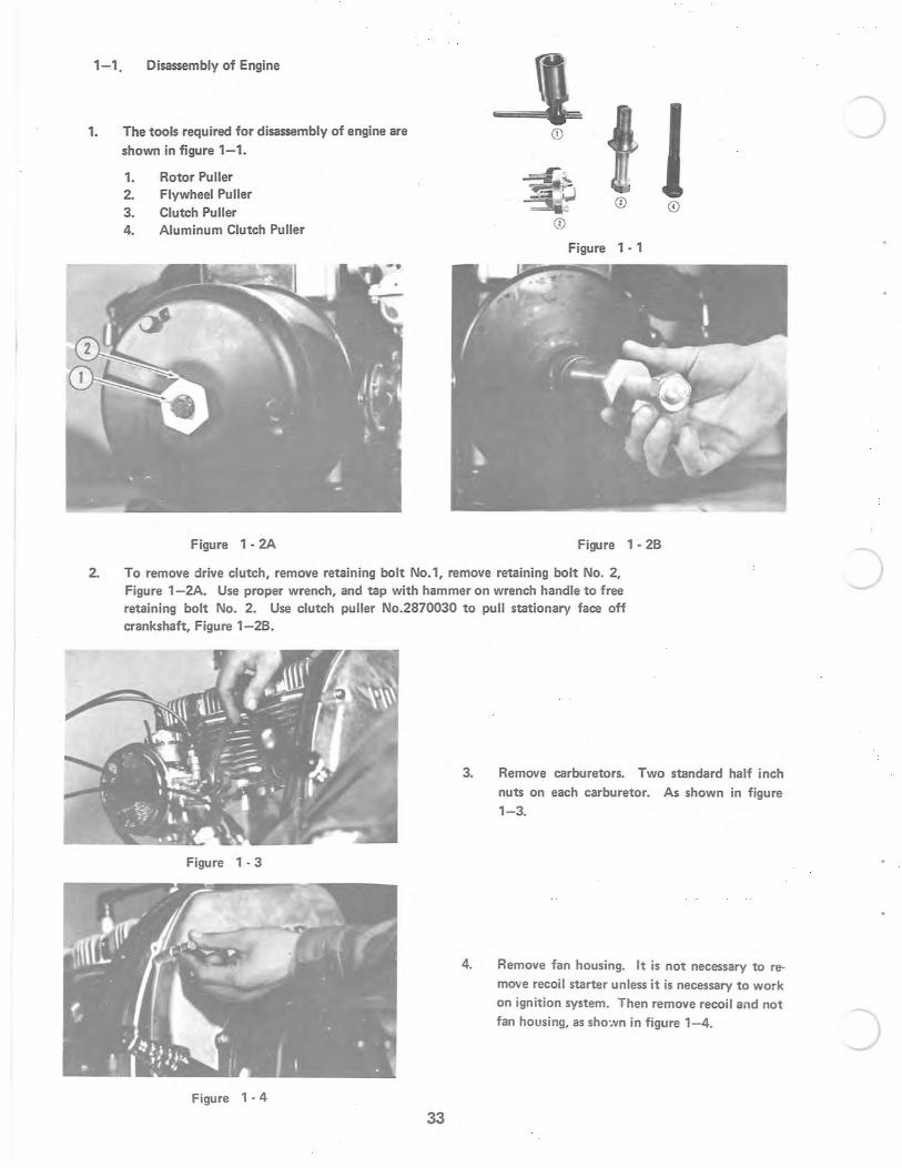
1-1 Disassembly of Engine
1. The tools required for disassembly of engine are shown in figure 1-1.
1. 2. 3. 4.
Rotor Puller Flywheel Puller Clutch Puller Aluminum Clutch Puller
Figure 1· 2A
Figure 1· 1
Figure 1 · 2B
2. To remove drive clutch, remove retaining bolt No.1, remove retaining bolt No.2, Figure 1-2A. Use proper wrench, and tap with hammer on wrench handle to free retaining bolt No.2. Use clutch puller No.2870030 to pull stationary face off crankshaft, Figure 1-2B.
Figure 1 ·3
Figure 1·4
33
3. Remove carburetors. Two standard half inch nuts on each carburetor. As shown in figure 1-3.
4. Remove fan housing. It is not necessary to reo move recoil starter unless it is necessary to work on ignition system. Then remove recoil and not fan housing, as sho".vn in figure 1-4.
J
c
c
c
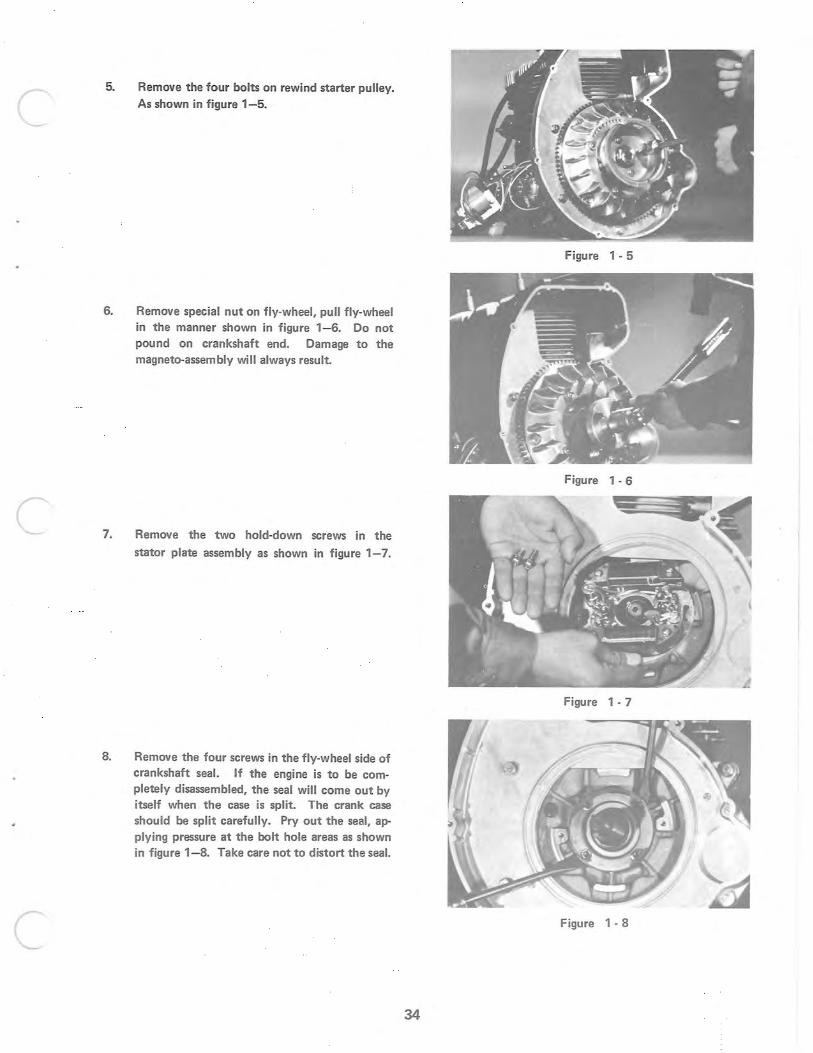
5. Remove the four bolts on rewind starter pulley. As shown in figure 1-5.
6. Remove special nut on fly-wheel, pull fly-wheel in the manner shown in figure 1- 6. Do not pound on crankshaft end. Damage to the magneto-assembly will always result.
7.
8.
Remove the two hold-down screws in the
stator plate assembly as shown in figure 1- 7.
Remove the four screws in the fly-wheel side of crankshaft seal. If the engine is to be completely disassembled, the seal will come out by itself when the case is split. The crank case should be split carefully. Pry out the seal, applying pressure at the bolt hole areas as shown in figure 1-8. Take care not to distort the seal.
Figure 1- 5
Figure 1 - 6
Figure 1 - 7
Figure 1 - 8
34
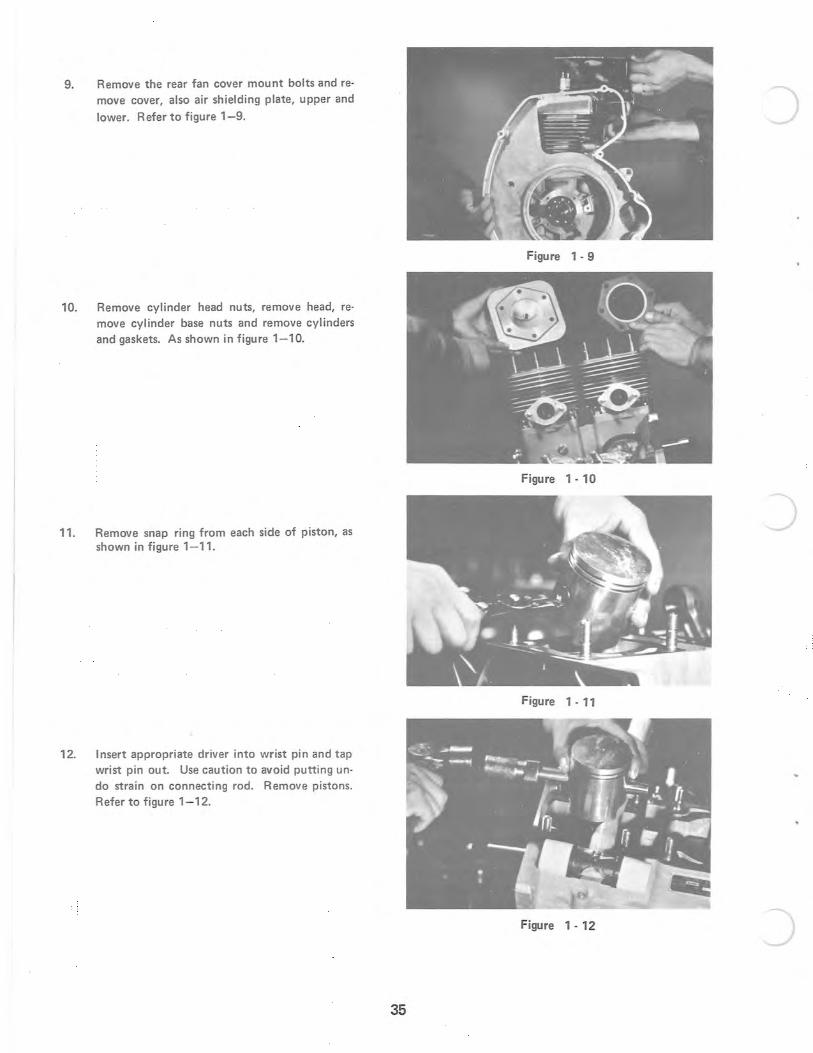
9. Remove the rear fan cover mount bolts and reo move cover, also air shielding plate, upper and
lower. Refer to figure 1- 9.
10. Remove cylinder head nuts, remove head, remove cylinder base nuts and remove cylinders and gaskets. As shown in figure 1-10.
11. Remove snap ring from each side of piston, as shown in figure 1-11.
12. Insert appropriate driver into wrist pin and tap wrist pin out. Use caution to avoid putting undo strain on connecting rod. Remove pistons. Refer to figure 1- 12.
35
)
Figure 1 - 9
Figure 1 - 10
)
Figure 1 - 11
Figure 1 - 12 )
c
c
c
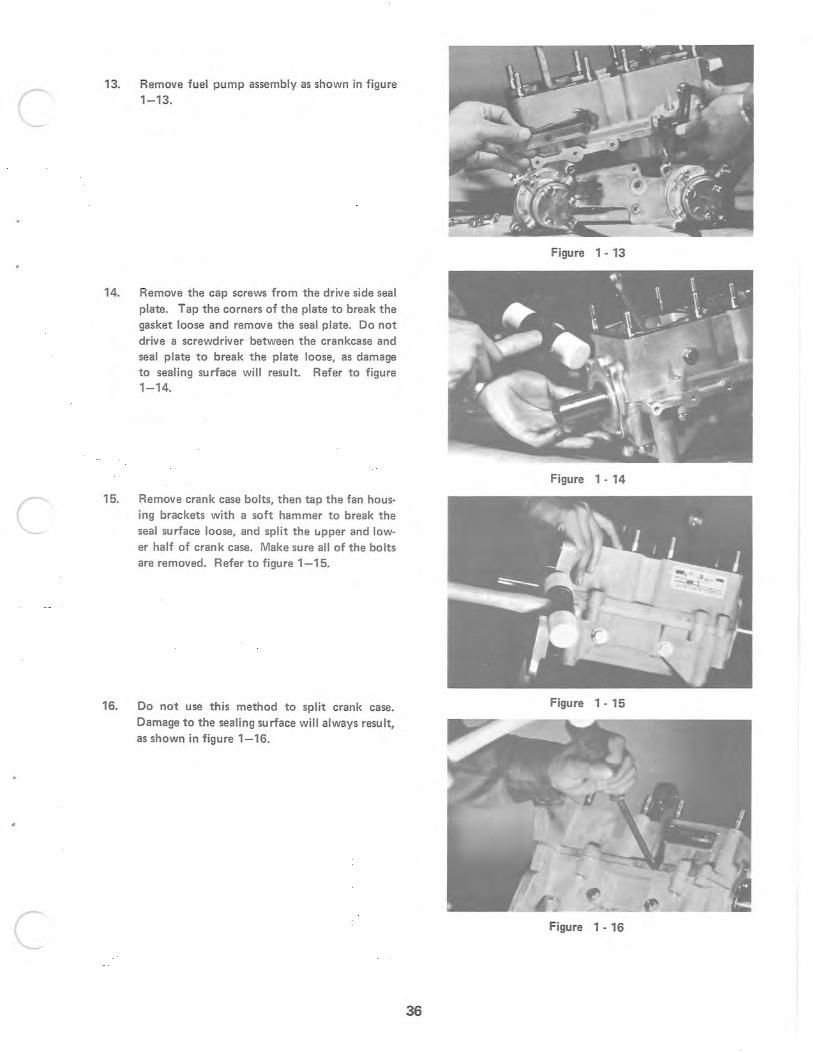
13. Remove fuel pump assembly as shown in figure 1-13.
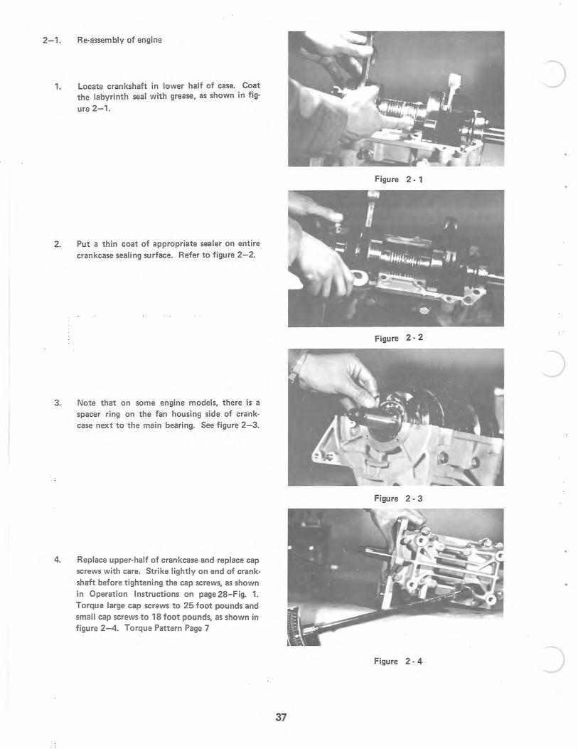
14. Remove the cap screws from the drive side seal plate. Tap the corners of the plate to break the gasket loose and remove the seal plate. Do not drive a screwdriver between the crankcase and seal plate to break the plate loose, as damage to sealing surface will result. Refer to figure 1-14.
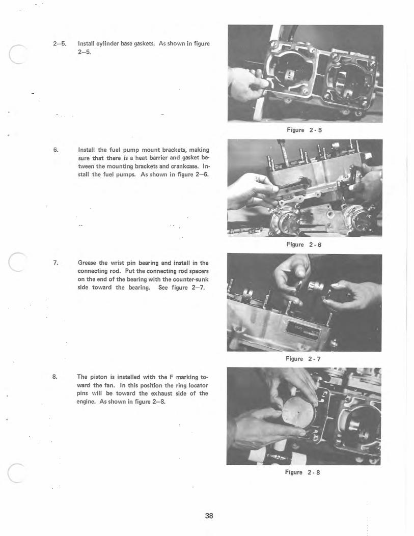
15. Remove crank case bolts, then tap the fan housing brackets with a soft hammer to break the seal surface loose, and split the lApper and lower half of crank case. Make sure all of the bolts are removed. Refer to figure 1- 15.
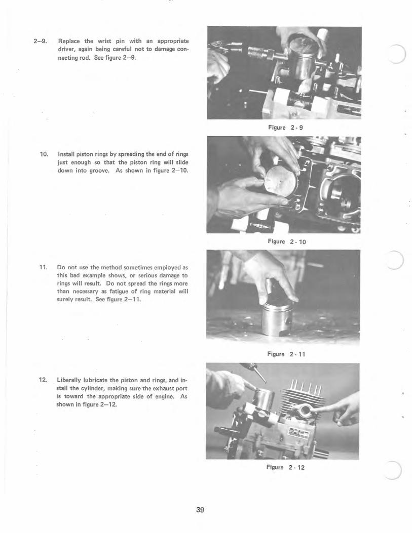
16. Do not use this method to split crank case. Damage to the sealing surface will always result, as shown in figure 1-16.
Figure 1 - 13
Figure 1 - 14
Figure 1 - 15
Figure 1 - 16
36
2-1 . Re-assembly of engine
1. Locate crankshaft in lower half of case. Coat the labyrinth seal with grease, as shown in fig-
ure 2- 1.
2. Put a thin coat of appropriate sealer on entire crankcase sealing surface. Refer to figure 2-2.
3. Note that on some engine model s, there is a spacer ring on the fan housing side of crankcase next to the main bearing. See figure 2- 3.
4. Replace upper-half of crankcase and replace cap screws with care. Strike lightly on end of crankshaft before tightening the cap screws, as shown in Operation Instructions on page 2a-Fig_ 1. Torque large cap screws to 25 foot pounds and small cap screws to 18 foot pounds, as shown in figure 2-4. Torque Pattern Page 7
37
J
Figure 2 - 1
Figure 2 - 2
J
Figure 2 - 3
Figure 2 - 4 )
c
c
c
2-5. Install cylinder base gaskets. As shown in figure
2- 5.
6. Install the fuel pump mount brackets, making sure that there is a heat barrier and gasket between the mounting brackets and crankcase. Install the fuel pumps. As shown in figure 2-6.
7. Grease the wrist pin bearing and install in the connecting rod . Put the connecting rod spacers on the end of the bearing with the counter-sunk side toward the bearing. See figure 2- 7_
8. The piston is installed with the F marking toward the fan. In this position the ring locator pins will be toward the exhaust side of the engine. As shown in figure 2-8.
38
Figure 2 - 5
Figure 2 - 6
Figure 2 - 7
Figure 2 - 8
2-9. Replace the wrist pin with an appropriate driver, again being careful not to damage connecting rod. See figure 2-9.
10. Install piston rings by spreading the end of rings just enough so that the piston ring will slide down into groove. As shown in figure 2-10.
11. Do not use the method sometimes employed as this bad example shows, or serious damage to rings will result. Do not spread the rings more than necessary as fatigue of ring material will surely result. See figure 2-11.
12. liberally lubricate the piston and rings, and install the cylinder, making sure the exhaust port is toward the appropriate side of engine. As shown in figure 2-12.
39
Figure 2 - 9
Figure 2 - 10
Figure 2 - 11
Figure 2 - 12 )
c
c
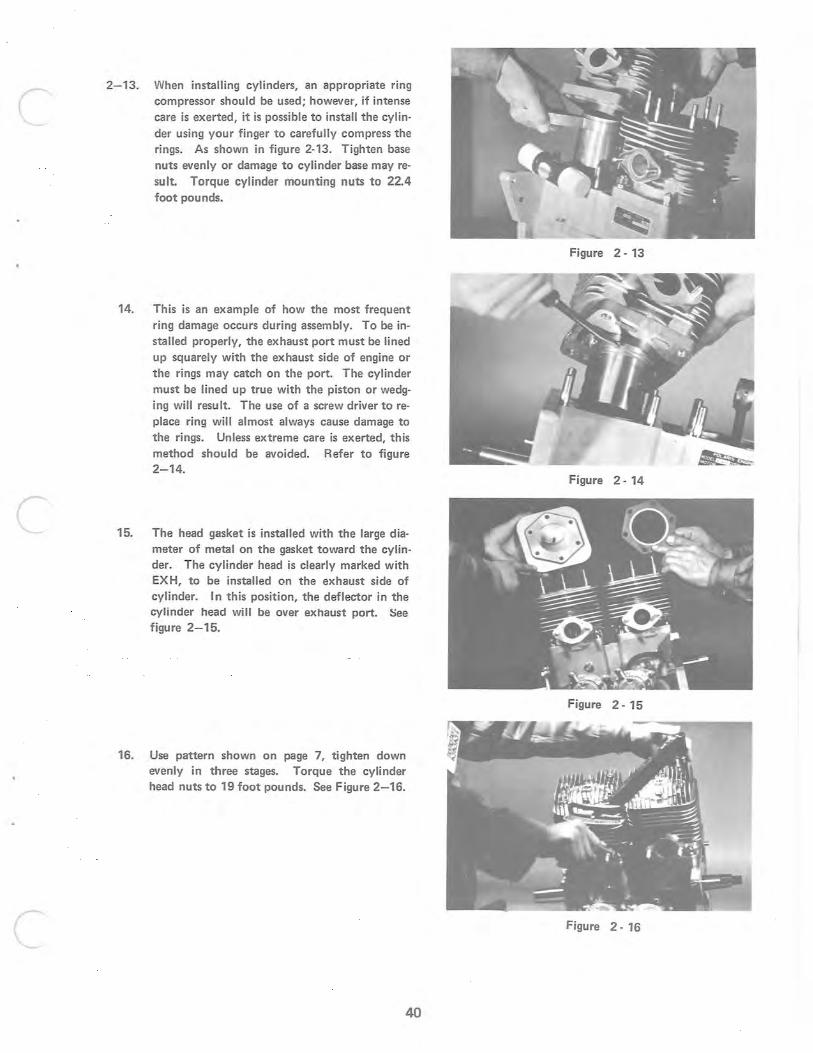
2-13. When installing cylinders, an appropriate ring compressor should be used; however, if intense care is exerted, it is possible to install the cylinder using your finger to carefully compress the rings. As shown in figure 2-13. Tighten base nuts evenly or damage to cylinder base may result. Torque cylinder mounting nuts to 22.4 foot pou nds.
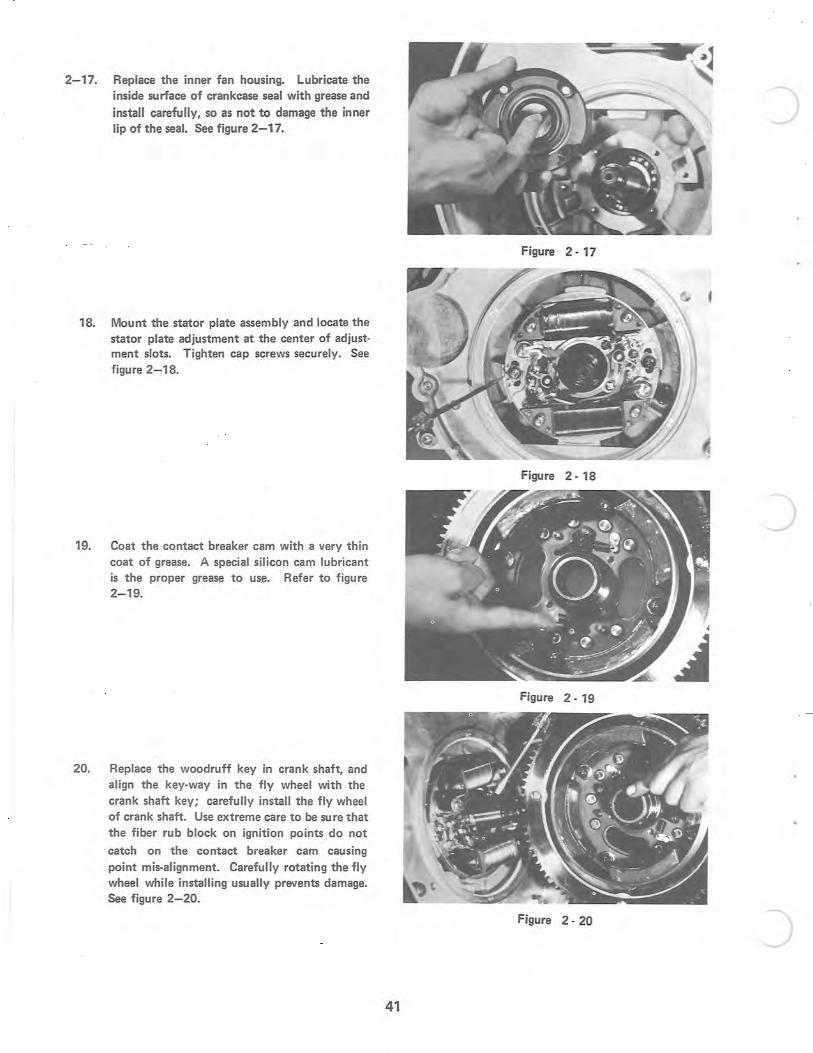
14. This is an example of how the most frequent ring damage occurs during assembly. To be installed properly, the exhaust port must be lined up squarely with the exhaust side of engine or the rings may catch on the port. The cylinder must be lined up true with the piston or wedging will result. The use of a screw driver to replace ring will almost always cause damage to the rings. Unless extreme care is exerted, this method should be avoided. Refer to figure 2- 14.
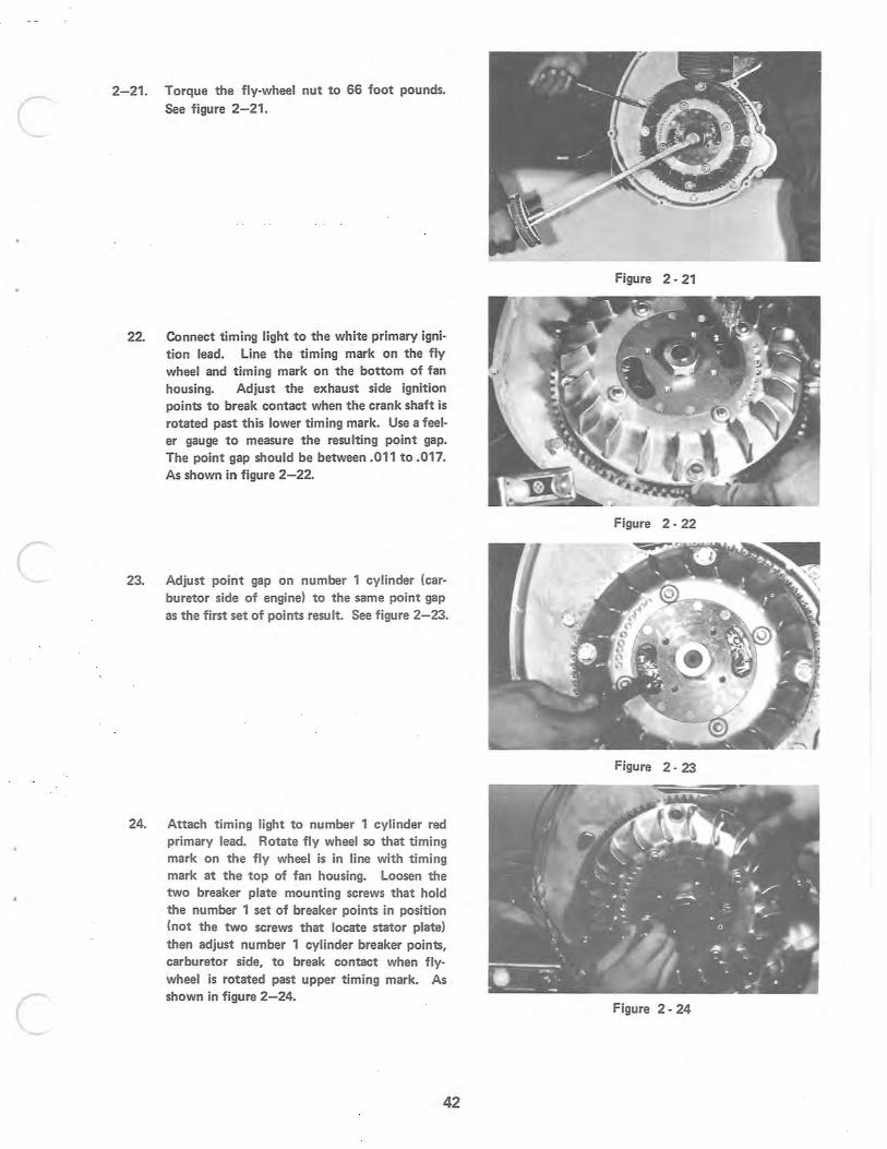
15. The head gasket is installed with the large diameter of metal on the gasket toward the cylinder. The cylinder head is clearly marked with EXH, to be installed on the exhaust side of cylinder. In this position, the deflector in the cylinder head will be over exhaust port. See figure 2-15.
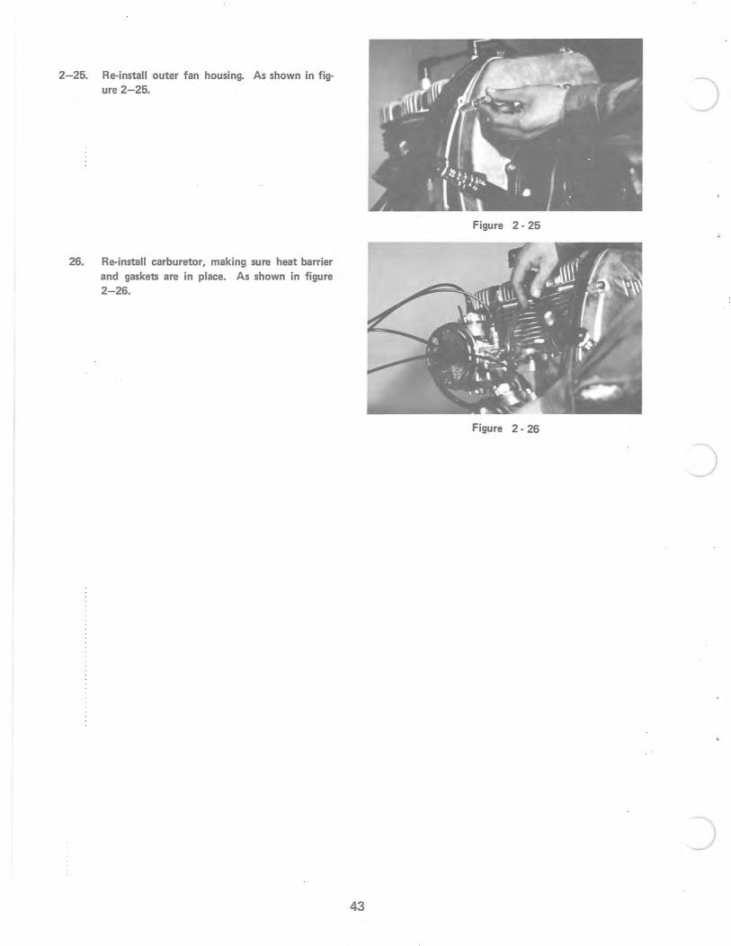
16. Use pattern shown on page 7, tighten down evenly in three stages. Torque the cylinder head nuts to 19 foot pounds. See Figure 2- 16.
Figure 2 - 13
Figure 2 - 14
Figure 2 - 15
C Figure 2 - 16
40
2- 17. Replace the inner fan housing. Lubricate the inside surface of crankcase seal with grease and install carefully, so as not to damage the inner lip of the seal. See figure 2-17.
18. Mount the stator plate assembly and locate the stator plate adjustment at the center of adjustment slots. Tighten cap screws securely. See figure 2-18.
19. Coat the contact breaker cam with a very thin coat of grease. A special silicon cam lubricant is the proper grease to use. Refer to figure 2-19.
20. Replace the woodruff key in crank shaft, and align the key-way in the fly wheel with the crank shaft key; carefully install the fly wheel of crank shaft. Use extreme care to be sure that the fiber rub block on ignition points do not
catch on the contact breaker cam causing point mis-alignment. Carefully rotating the fly wheel while installing usually prevents damage. See figure 2-20.
41
)
Figure 2 - 17
Figure 2 - 18
J
Figure 2 - 19
Figure 2 - 20 J
c
c
c
2-21. Torque the fly-wheel nut to 66 foot pounds. See figure 2-21.
22. Connect timing light to the white primary ignition lead. Line the timing mark on the fly wheel and timing mark on the bottom of fan housing. Adjust the exhaust side ignition points to break contact when the crank shaft is rotated past this lower timing mark. Use a feeler gauge to measure the resulting point gap. The point gap should be between .011 to .017. As shown in figure 2- 22.
23. Adjust point gap on number 1 cylinder (carburetor side of engine) to the same point gap as the first set of points result. See figure 2-23.
24. Attach timing light to number 1 cylinder red primary lead. Rotate fly wheel so that timing mark on the fly wheel is in line with timing mark at the top of fan housing. Loosen the two breaker plate mounting screws that hold the number 1 set of breaker points in position (not the two screws that locate stator plate) then adjust number 1 cylinder breaker points, carburetor side, to break contact when flywheel is rotated past upper timing mark. As shown in figure 2-24.
42
Figure 2 - 21
Figure 2 - 22
Figure 2 - 23
Figure 2 - 24
2-25. Re-install outer fan housing. As shown in figure 2-25.
26. Re-install carburetor, making sure heat barrier and gaskets are in place. As shown in figure 2-26.
43
J
Figure 2 - 25
Figure 2 - 26
J
)
c
c
c
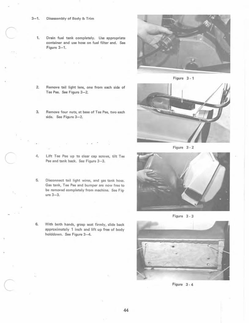
3-1. Disassembly of Body & Trim
1. Drain fuel tank completely. Use appropriate container and use hose on fuel filter end. See Figure 3-1.
2. Remove tail light lens, one from each side of Tee Pee. See Figure 3- 2.
3. Remove four nuts, at base of Tee Pee, two each side. See Figure 3-2.
4. Lift Tee Pee up to clear cap screws, tilt Tee Pee and tank back. See Figure 3-3.
5. Disconnect tail light wires, and gas tank hose. Gas tank, Tee Pee and bumper are now free to be removed completely from machine. See Figure 3-3.
6. With both hands, grasp seat firmly, slide back approximately 1 inch and lift up free of body holddown. See Figure 3 - 4.
44
Figure 3 - 1
Figure 3 - 2
Figure 3 - 3
•
Figure 3 - 4
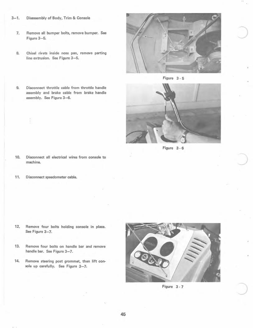
3-1. Disassembly of Body, Trim & Console
7. Remove all bumper bolts, remove bumper. See Figure 3-5.
8. Chisel rivets inside nose pan, remove parting line extrusion. See Figure 3 - 5.
9. Disconnect throttle cable from throttle handle assembly and brake cable from brake handle assembly. See Figure 3 - 6.
10. Disconnect all electrical wires from console to machine.
11. Disconnect speedometer cable.
12. Remove four bolts holding console in place. See Figure 3- 7.
13. Remove four bolts on handle bar and remove handle bar. See Figure 3- 7.
14. Remove steering post grommet, then lift console up carefully. See Figure 3- 7.
J
Figure 3 - 5
Figure 3 - 6
Figure 3 - 7 J 45
c
c
c
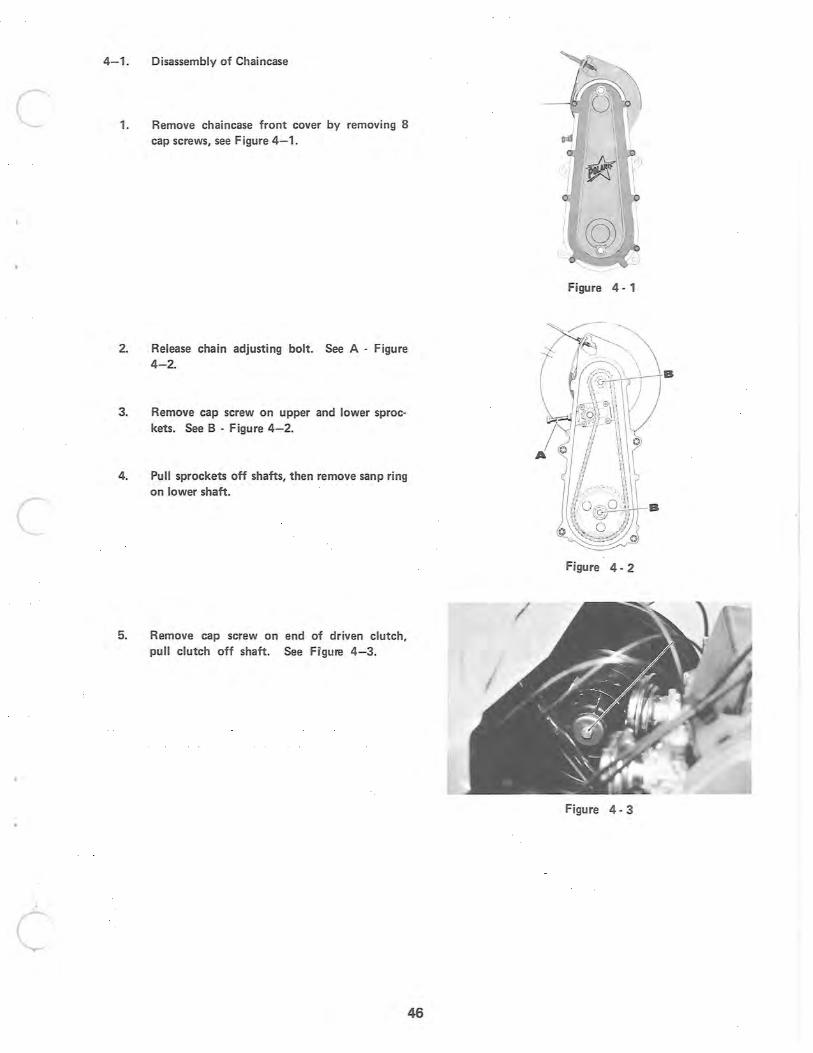
4-1. Disassembly of Chaincase
1. Remove chaincase front cover by removing 8 cap screws, see Figure 4 - 1.
2. Release chain adjusting bolt. See A - Figure 4-2.
3. Remove cap screw on upper and lower sprockets. See B - Figure 4- 2.
4. Pull sprockets off shafts, then remove sanp ring on lower shaft.
5. Remove cap screw on end of driven clutch, pull clutch off shaft. See Figure 4- 3.
46
Figure 4 - 1
Figure 4 - 2
Figure 4 - 3
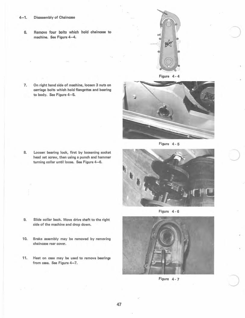
4- 1. Disassembly of Chaincase
6. Remove four bolts which hold chaincase to machine. See Figure 4-4.
7. On right hand side of machine, loosen 3 nuts on carriage bolts which hold flangettes and bearing to body. See Figure 4- 5.
8. Loosen" bearing lock, first by loosening socket head set screw, then using a punch and hammer turning collar until loose. See Figure 4-6.
9. Slide collar back. Move drive shaft to the right side of the machine and drop down.
10. Brake assembly may be removed by removing chaincase rear cover.
11. Heat on case may be used to remove bearings from case. See Figure 4- 7.
)
Figure 4 - 4
Figure 4 - 5
Figure 4 - 6
Figure 4 - 7
47
c
c
c
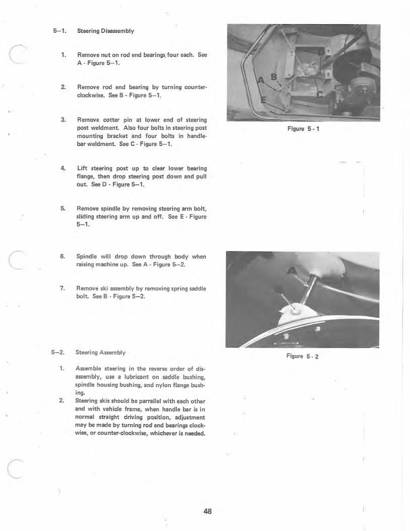
5- 1. Steering Disassembly
1. Remove nut on rod end bearings. four each. See A · Figure 5-1.
2. Remove rod end bearing by turning counter· clockwise. See B . Figure 5- 1.
3. Remove cotter pin at lower end of steering post weldment. Also four bolts in steering post mounting bracket and four bolts in handle· bar weldment. See C . Figure 5- 1.
4. lift steering post up to clear lower bearing flange, then drop steering post down and pull out. See D - Figure 5- 1.
5. Remove spindle by removing steering arm bolt, sliding steering arm up and off. See E · Figure 5-1 .
6. Spindle will drop down through body when raising machine up. See A . Figure 5- 2.
7. Remove ski assembly by removing spring saddle bolt. See B . Figure 5- 2.
5- 2. Steering Assembly
1. Assemble steering in the reverse order of dis· assembly, use a lubricant on saddle bushing, spind le housing bushing, and nylon flange bushing.
2. Steering skis should be parrallel with each other and with vehicle frame, when handle bar is in normal straight driving position, adjustment may be made by turning rod end bearings clockwise, or counter-clockwise, whichever is needed.
48
Figure 5 - 1
Figure 5 - 2
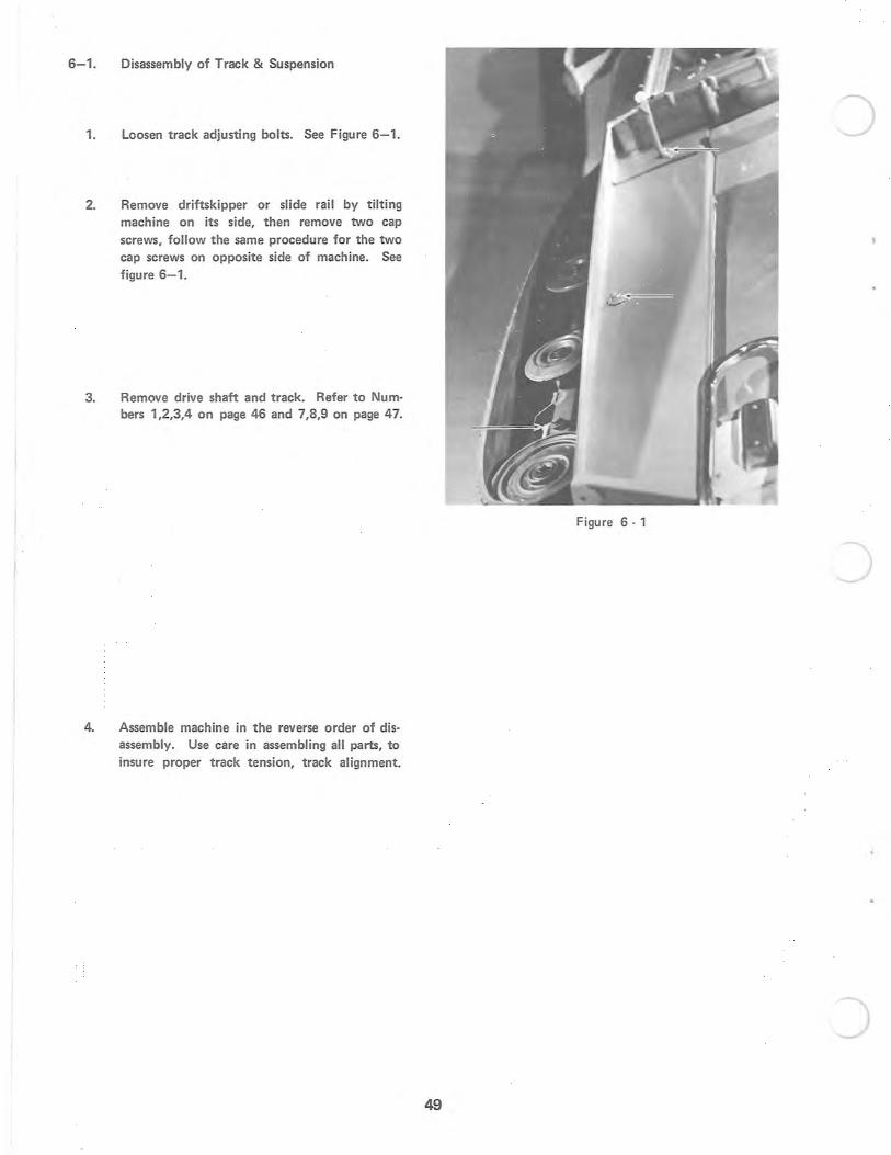
6- 1. Disassembly of Track & Suspension
1. Loosen track adjusting bolts. See Figure 6- 1.
2. Remove driftskipper or slide rail by tilting machine on its side, then remove two cap screws, follow the same procedure for the two cap screws on opposite side of machine. See figure 6- 1.
3. Remove drive shaft and track. Refer to Numbers 1,2,3,4 on page 46 and 7,8,9 on page 47.
4. Assemble machine in the reverse order of disassembly. Use care in assembling all parts, to insure proper track tension, track alignment.
Figure 6 · 1
49
c
c
c
6- 2. Power Slide
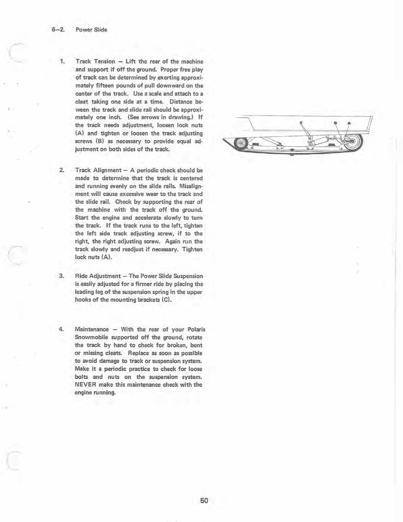
1. Track Tension - lift the rear of the machine and support if off the ground. Proper free play of track can be determined by exerting approximately fifteen pounds of pull downward on the center of the track. Use a scale and attach to a cleat taking one side at a time. Distance beween the track and slide rail should be approximately one inch. (See arrows in drawing.) If the track needs adjustment, loosen lock nuts (A) and tighten or loosen the track adjusting screws (8) as necessary to provide equal adjustment on both sides of the track.
2. Track Alignment - A periodic check should be made to determine that the track is centered and running evenly on the slide rails. Misalignment will cause excessive wear to the track and the slide rail. Check by supporting the rear of the machine with the track off the ground. Start the engine and accelerate slowly to turn the track. If the track runs to the left, tighten the left side track adjusting screw, if to the right, the right adjusting screw. Again run the track slowly and readjust if necessary. Tighten lock nuts (A).
3. Ride Adjustment - The Power Slide Suspension is easily adjusted for a firmer ride by placing the leading leg of the suspension spring in the upper hooks of the mounting brackets (C).
4. Maintenance - With the rear of your Polaris Snowmobile supported off the ground, rotate the track by hand to check for broken, bent or missing cleats. Replace as soon as possible to avoid damage to track or suspension system. Make it a periodic practice to check for loose bolts and nuts on the suspension system. NEVER make this maintenance check with the engine running.
50
6-3. Driftskipper
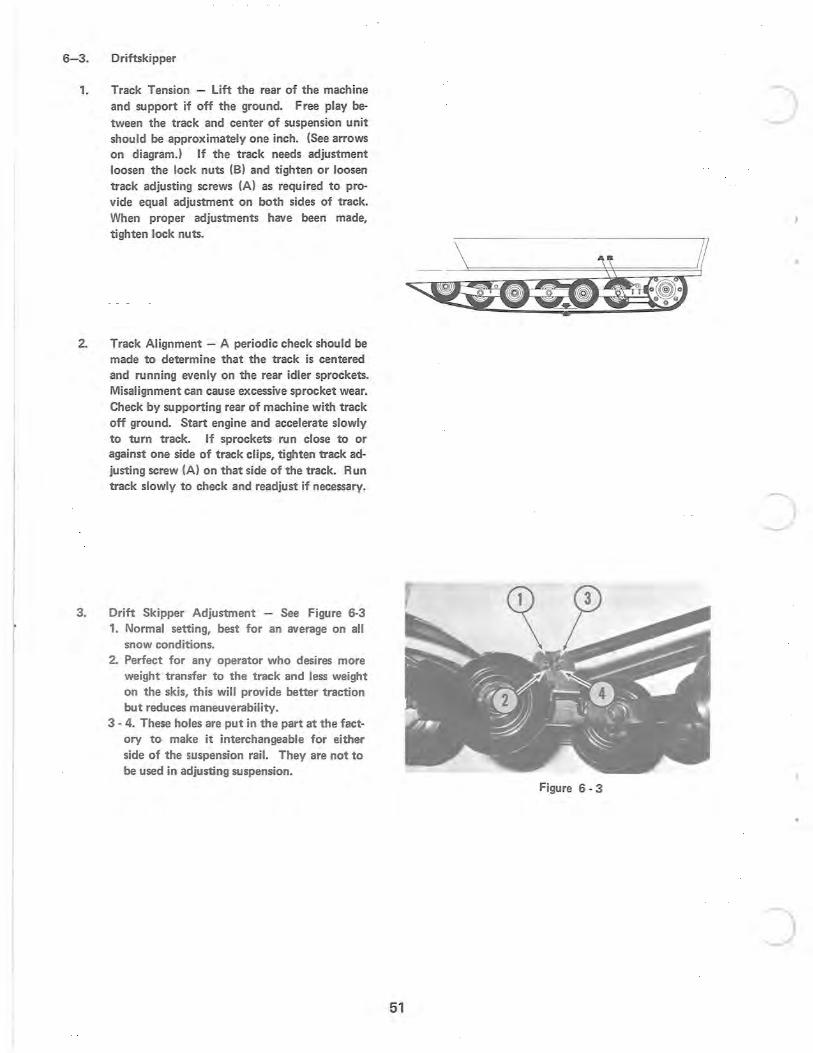
1. Track Tension - Lift the rear of the machine and support if off the ground. Free play be· tween the track and center of suspension unit should be approximately one inch. (See arrows on diagram.) If the track needs adjustment loosen the lock nuts (B) and tighten or loosen track adjusting screws (A) as required to provide equal adjustment on both sides of track. When proper adjustments have been made, tighten lock nuts.
2. Track Alignment - A periodic check should be made to determine that the track is centered and running evenly on the rear idler sprockets. Misalignment can cause excessive sprocket wear. Check by supporting rear of machine with track off ground. Start engine and accelerate slowly to turn track. If sprockets run close to or against one side of track clips, tighten track adjusting screw (A) on that side of the track. Run track slowly to check and readjust if necessary.
3. Drift Skipper Adjustment - See Figure 6-3 1. Normal setting, best for an average on all
snow conditions. 2. Perfect for any operator who desires more
weight transfer to the track and less weight on the skis, this will provide better traction but reduces maneuverability.
3 - 4. These holes are put in the part at the factory to make it interchangeable for either side of the suspension rail. They are not to be used in adjusting suspension.
Figure 6 - 3
51

c
c
..
c

o i
-"'it " ,/ .
o
o


![Catalog C-002 Rev. B · 1] ±0.001 inches [0.03 mm] for male contact mating diameters. 2] ±0.003 inches [0.08 mm] for contact termination diameters. 3] ±0.005 inches [0.13 mm] for](https://img.pdfslide.net/doc/110x75/5fb5a758af199938f61750b5/catalog-c-002-rev-b-1-0001-inches-003-mm-for-male-contact-mating-diameters.jpg)