Embed Size (px)
Citation preview

CORECO_RE_SOREXIT STA_ESTUDY -
II. F_NAt.REPOI_,
R.F. Behlke, £.A, Burclsa,ll_ E, Canal _lr. and N. O. KO_ le(ktober 197g
UNITED_ECHNOLOG]_I_$CORL_ATIONPratt &Whttney Atrc_aft Q_oupCO_e_al Pr6ductsDtviston
Prepared for
NATIONA__RONAUTICSANO SPACEADMINISTRATIONNASA-L_IsResearchCenter
ContracttIAS3-20_78
"19800"14823
https://ntrs.nasa.gov/search.jsp?R=19800014823 2018-07-12T02:20:32+00:00Z

FOREWORD
The study descrtbed herei_ was perfQrmedunder NASAContract NAS-3-2057Bby the Pratt & WhitneyAircraft_roup,CommercialProductsDivision,United TechnologiesCorpora_ion_u_dor the directionof Mr. N, T.
, Monsarrat,ProgramManager.The NASA ProjectManager was Mr. R. S.' Ruggeri,NASA_-ILewisResearchCenter,Fluid SystemComponentsDivision,
,_! Fan and CompressorBranch.The work was performedduringthe period20_" October1976through30 June 1979,The authorswish tu acknowledgethe
participationand contributionsin the fulfilImentof f.hiscentractbyMessrs.W. T. l;an_eyand H. A. Harmonof the Pratt& WhitneyAircraft
_)I Group and by Mr. C. L Crockettof the UnitedTechr,ol.ogiesResearch
:_ Center,TestFacIIitiesoOperatlonsGroup.'.L_
PRECEDINGPAL_ UwJ.'_ANOT FILMED

TABLEOF CONTENTS
Titlw_._.,e.i
SUMMARY %
' INTRODUCTION II
i_t. APPARATUS 2AerodynamicDestgn 2MechanicalDesl9. 3Instrumentation andCalibration 4
,_ PROCEDURE 7Test P_ocedure 7Data Reduction Techniclues 7
RESULTSAND DISCUSSION 8Overa_I Performance 8
_I, StageStaticPressureCharacteristics gSpanwiseProfiles 11
SUMMARYOF RESULTS 12I
REFERENCES 13
APPENDIXESvA SymbolsandAbbreviations 53B DataReductionEquations 55C Tabulationof InletandExitSpanwiseTestData 61
DISTRIBUTIONLIST 83
t
, i
4
k_t,,¢
iv
1980014823-TsA()z

; LISTOLILLU_TRATIONS
%' ....
r 1 Schema_c of the 3Sl/3S2 _pres_ors 15
,' 2 Photogragbof a TypicalRotorAssembly 16
_,i:! 3 Photographof a TypicalStatorAssembly 17
4 Three-StageAxial-FlowCompressorRig Facility 18
5 AxialLocationsof InstrumentationPlanesfor•_ the3SI and3S2 Compressors 19
6 TypicalTotalPressureRakes 20
7 TypicaITotaITemperatureRakes 21
8 DataAnalysisFlowChart 22
9 Comparisonof 3S1 and3S2 OverallPerformanceBasedon Averageof Six RepeatTestSpeedlines 23
10 AdiabaticEfficiencyandPressureRatioasFunctionsof CorrectedWeightFlowfor 3SIConfigurationatDesignSpeed 24
11 AdiabaticEfficiencyas a Functionof PressureRatiofor 3Sl Configurationat DesignSpeed 25
12 TotalTemperatureRatioas a FunctionofCorrectedWeightFlowfor 3S1 Configurationat
DesignSpeed 26 i
13 PressureRatioandAdiabaticEfficiencyasFunctionsof CorrectedWeightFlowfor 3SI 1Configurationat 85 and 105PercentDesign !Speed 27
14 AdiabaticEfficiencyas a FunctionofPressureRatiofor 3SlConfigurationat 85and105 PercentDesignSpeed 28
15 TemperatureRatioas a Functionof CorrectedWeightFlowfor 3SI Configurationat 85 and105Percentof DesignSpeed 29 ,;
i
vh
1980014823-TSA05

LIST OF ILLUSTRATIONS(Continued)
16 AdiabaticEfficiencyand PressureRatio asFunctionsof CorrectedWeight Flow for 3SIConfiguratlon.atDesign Speed - DeteriorationCheck 30
17 AdiabaticEfficiencyas a Function of Pressure-Ratio for 3SI Configurationat Design Speed -Deterioration Check 31
_i_ 18 TemperatureRatio as Functionof CorrectedWeight" Flow for 3SI Configurationat Design Speed-
Deterioration Check 32
_' Ig AdiabaticEfficiencyand PressureRatio as
Functionsof CorrectedWeight Plow for 3S2- Configurationat Design Speed 33if.l
20 AdiabaticEfficiencyas a Functionof-, PressureRatio for 3S2 Configurationat
Design Speed 34 !
•J 21 TemperatureRatio as a Functior_of CorrectedWeight Flow for 3S2 Configurationat DesignSpeed 35
q
22 AdiabaticEfficiencyand PressureRatio asFunctionsof CorrectedFlow for 3S2Configurationat 85 and 105 PercentofDesign Speed 36
23 AdiabaticEfficiencyas a FunctionofPressureRatio for 3S2 Configurationat 85and 105 Percentof Design Speed 37
24 TemperatureRatio as a Functionof CorrectedWeight Flow for 3S2 Configurationat B5 and105 PercentDesign Speed 38
25 AdiabaticEfficiencyand PressureRatio asFunctionsof CorrectedWeight Flow for 3S2Configurationat Design Speed - Deterioration
_' Check 39
26 AdiabaticEfficiencyas a Functionof Pressure" Ratio for 3S2 Configurationat Design Speed -
Deterioration Check 40
e
.. vi
--o_
" ' " "............ e8 TSA06°..... 1

il
LIST OF ILLUSTRATIONS(Continued)'i
ti' FiL_ur_ Title
27 TemperatureRatio as a Functionof CorrectedWeight Flow for 3S2 Configurationat DesignSpeed - DeteriorationCheck 41
' 28 PressureRise Coefficientas a Functionof Flow., Coefficientfor 351 Configurationat Design
_I Speed 42,._ 29 PressureRise Coefficientas a Functionof Flow
Coefficientforvv3S2Configurationat DesignSpeed 43
30 PressureRise Coefficientas a Functionof FlowCoefficientfor 3S1 Configurationat 85 Percent
. Design Speed 44i
_ 31 PressureRise Coefficientas a Functionof F lowCoefficientfor 3S2 Configurationat 85 Percent
., Design Speed 45
32 PressureRise Coefficientas a Functionof Flow,_ Co--fficientfor 3SI Configurationat 105 Percent
Design Speed 46
33 PressureRise Coefficientas a Functionof FlowCoefficientfor 3S2 Configurationat 105 PercentDesign Speed 47
34 AdiabaticEfficiency,TemperatureRatio, andPressureRatio as Functionsof PercentSpan for "@3S1 and 3S2 Configurationsat Peak Efficiency;DesignSpeed 48
35 AdiabaticEfficiency,TemperatureRatio, andPressureRatio as Functionsof PercentSpan for3S1 and 3S2 Configurationsat Near Stall; DesignSpeed 49
36 Inlet Total Pressureand Total Temperatureas'_ Functionsof PercentSpan _or 3S1 and 3S2
Configurationsat Peak Efficiency;Design Speed 50
i 37 Inlet Tota! Pressure and Total TemperatureasFunctionsof PercentSpan for 3SI and 3S2Configurationsat Near Surge; Design Speed 51
o
,' viir,-'i'
...... 1980014823-TSA07

.#'
LISTOF TABLES
)! I Princ4palAerodynamicD_ign Parameters 2
, II PerformanceInstrumentation 5,l
_! III OvaralI PerformanceSumar-y g
W_
/." viii
_p
..... _LIL II 1 I 1 IN • " II i • • • _ _ "-
1980014823-TSA08

CORECOMPRESSOREXITSTAGESTUDY
II.K-INALREPORT
byw'/
:!.: R.F. Behlke,E. A. BurdsaLl,E. Canal,Jr. andN_,8,Kern
Pratt& WhitneyAircraftGroup
i!I SUMMARY
'_ Tests were conductedon two three-stagecompressors,designedwith as-, pact ratiosof 0,81 and 1.22,to acquiredetailedoverallaerodyno_i¢_ performancedata on the effectsof aspectratio in high hub-tipratio
stages,similarto those at the rear of advancedmultistagecompres-_ sors.Both compressorswere designedfor 15 percentsurgemargin.The
_- 0,81 aspectratiocompressor(3SI)was designedfor a higherpressure 1'i ratiothanthe 1.22 aspectratiocompressor(3S2)in recognitionof the l__ increasedcapabilitybelievedto existat loweraspectratios. 1
1
The test resultsshowedthat the 0.81 aspectratiocompressorexceededits design surge margin by nine percent despiteits higher designloadingand demonstrateda peak adiabaticefficiencyof 86.1 percent.The 1.22 aspectratio compressorachieveda higherpeak efficiencylevel(87.0percent)than the 0.81 aspectratiocompressor,but fellshortof its surgemargingoal by threepercent.The loweraspectratiocompressorexhibitedgreaterefficiencyin the endWallregionsand adepressedefficiencyin the mldspanregions.The first stage of theloweraspectratiocompressorexhibiteda stalledstaticpressurechar-acteristicwhileall threestagesof the higheraspectratiocompres-sor stalleduniformlybut belowtheirpeakdesignlevel.
INTRODUCTION ..
: Compressorsfor advancedaircraftturbofanenginesmust combinehighefficiencywith adequatestabilitymargin in a compact,light-weightconfiguration.Pratt& WhitneyAircraftexperience(ref.I) with single
._ and multistage compressorssuggests that low aspect ratio airfoils havethe potential to meet these requirements by combining high loading capability with previously developed low endwall loss technology. A testprogram1w&s devised to determine the benefits of low aspect ratio inthe high hub-tipratiorear stageenvironmentof an advancedmultistagecompressor.The aerodynamicconfigurationchosenfor testingwas basedon the lastthreestagesof the elght-stage,AdvancedMultistageAxialFlow Compressor(AMAC)studiedunder a previouscontract(ref.2). AlowMach numberthree-stagerig was s_.lectedas the testvehicle,
This reportpresentsthe resultsof both the 0,81 aspectratio (3SI)compressorand the 1.22aspectratio(3S2)compressortests.Detailsofthe designof eachof thesecompressorsarepresentedin ref.3,
"1_9_UU-I/-.I._Zj /o_u_

IT
APPARATUS
AERODYNAMICDESIGNi
Two three-_tag_compressors,designated351 and 3S2, were designedtodemonstrateimprovedbladingfor the rear stages of highly loaded,advancedcore compressors.A schematicof the 351 and 352 compressorsis shownin Figure1. The averageaspectratioof the 351 configurationwas 0.81,the overallpressureratioat designspeedwas 1,35,and theaveragediffusionfactor (O Factor)was 0.529,The 3S2 configuration
I was similarto 3S1, but was de._Ignedfor a fiftypercenthigheraspectratio (1.22),The principalaerodynamicde.qlgnparametersof the 3SI
_I and 3S2 compressorsare givenin TableI. The dBslgnm_=anwheelspeed,'i tip dianeter,and flow capacitywere establishedto be compatiblewithi the limitationsof an existingtestfacility.b, TABLEI
I. PRINCIPALAERODYNAMICDESIBNPARAMETERSi,i
"' 3S1 3S2InletCorrectedFlow;kg/sec 4.30 (9._47)_ _IT_Q'O-TIJT'4_/T
(Ibm/sec)CorrectedMeanWheelSpeed_ 167 (547) 167 (54:)
r" 50 percentSpan;m/sec(ft/sec)PressureRatio 1.357 1.324OveraIIAdiabatic Efficiency,% 88.30 88.70
, A_IJectRatio,Average 0.81 1.22
SoIidity,.Average 1.10 i.10InletHub TipRatio 0.915 0,915ExitHub-TipRatio 0.915 0.915WorkCoefficient-E-,Average 0.702 0.644FlowCoefficient- Cx/U,Average 0.440 0.444
i (50percentSpan)D Factor,Average* 0.52g 0.491P/(Po-P),Average 0.497 0.467Tip Clearance,Averagecm (in.) 0,033(0,013) 0.033(0.013)Reaction O.517 O,517
*D Factor Average = Sum of mass average diffusionfactors fromstreamlineanalysisfor the variousbladerows dividedby the numberofbladerows.
The aerodynamicdesign (see ref. 3) was perfomed in three steps.: First,the analyticaldesignsyst_ was adjustedto ensureperformance_' agreementwith data from testsof three-stagecompressorssimilarto_ the 3SI configuration.Next a preliminarydesignbasedon a meanline
approachprovideda roughflovpathand average.aerodynamicquantities.Finallya detailedfull-spandesign,whichutim,:eda streantlinecalcu-lationprocedure,was used to set bladinggeometryand finalizeflowpath dimensions.Circulararc mean camber line airfoilswith a 65seriesthicknessdistributionwere chosenfor all rowsbecauseof theirexcellentlowMach numberperformancecharacteristics.
, 2,4
¢
1980014823-TSAIO

iF
)
Ii MECHANICALDESIGN
C_ompre_or Rit
J
The ba._ic mechanical de_ign of the 3SI and 3S2 compressor rigs (_eeref, 3) eonsls_ed of an assembly of {nterlocklng aluminum rings, whichformed tile compressor case, and a _et of aluminum wheels, which were
_' keyed to a central shaft and formed th_ compressor h,_b, The 3SII compressor a_sembly Is _hown as the top half of the _chema_ic in
Figure I and 3S2 as tho lower half. A rotating drum design consistingof a rotor assemblysupportedby b_arings at the front and rear of the
compressorwas used for the .innerportion of the rig. The rotor assem-bly consisted of a stack of aluminum rotor blade carrier and spacerwheel@ keyed to a central shaft threaded at both ends. The stator as-sembly consisted of a stack of interlockingstarer vane carrier andspacer rings. The parts were secured in place by steel endplatesclamp-ed togetherby tie rods.
All bladingwa_ cast using an aluminum alloy material,A356-T6. Bladingattachmentwas accomplishedby mea_s of a bolt, which securedthe bladeor vane to the blade or vane carrier. Typical ,otor and cantilew:.redstarer assembliesare shown in Figure_ 2 and 3, respectively.
Test Facilit_#
The compressor test facility, located at the United TechnologiesResearchCenter, consists of the compressordrive system,the inlet and
, discharge flow ducting, and the data acquisition system. The drive,_ystemand compressor are $ocatedwithin a test cell. The operatingcontrols, monitoring instrumentation,and data acquisitionsystem arelocatedin a separatecontrolroom.
The major components of the compressor drive system are a DC e(ectricmotor and a speed-increasinggearbox. An automatic speed control isutilizedto maintain speed at a preset value.
Filtered ambientair is ducted into the test cell and through a plenumthat provides uniform pressure and temperature distributions at thecompressorinlet. A throttle downstreamof the compressorcontrols therate of airflowthrough the compressor.The flow is exhaustedthrough a
, duct containinga silencerto reduce noise leve!sbefore dischargingtothe atmosphere.The facility is shown schematicallyin Figure 4.
The ComputerizedPrecisionAcquisition Sequencing System (COMPASS) istlsedfor control, acquisil;ion,and recordingof the experimentaldata.Utilizinga minic_puter for control of the data acquisitionsequences,COMPASS can acquire parametersthat incSude identificationinformationand calibration data, as well as analog and digital transducer data. "The system is self calibratingvia primary and secondary pressure andvoltage standardsar.dis capable of a pressuremeasurementaccuracy of+0.I0 percent of full scale reading and a temperature measurement_ccuracy of +_0.14oc(+O.25OF).
3
W,'° ¢ ._ • ...............• i.
--- 1980014823-TSA11

D
l'
INSTRUMENTATIOr_-ANDCALIBRATION\
' _res_or Perfonn_n_In_tr_entatlon
RiB instrumentationwas sel@ctedto obtainoverallcompressorperform.ante.Wall staticpressureswere Incorporatedto evaluateindividual
! rotor as well as individualstagecharacteristicsrelativeto deslgnvalues, Figure 5 show_ the locationsof the overall performanceinstrumentationas well as the loca_IQnof the inter-bladerow staticpressuretaps,
C_npressorairflowwas calculatedfrom measuredtotaland staticpros-_ sures in an axial plane close to the bellmoutl_exit defined In--Figure 1
as station O. Total temperatures used tn the calculation were obtainedfrom probesat the compressorinlet instr_entatlonplane,station%(Figure5). Priorto the rig test program,a detailedflow calibrationwas performedin whichradialtraversesin-fourcircumferentialloca-tionsweremade at severalfFow rates.The aatawere integratedto es-
• tablish_he trueflow at the rig inletflowmeasuringplane.The true" flow was then correlatedwith the flow calculatedfrom the midspanin-
strumentationused durir_gth_ tests and the correlationwas used toestablist_a flow coefficientwhichwas appliedto all data,r.;sulting
_- in an accuracywithinonepercentof the trueflow.
Compressorrotor speedwas measuredby meansof a magneticpickup.Atachometerconvertedthe pulseratefrom the pickupintorotorspeedinr_. Accuracywas within0.1 percent.
Pressuresfrom pole rakesin the inlet and dischargeand from staticpressuretaps were sensed by gage type analogpressuretransducersmounted in multiportscar:lingvalves.These pneumaticswitcheswerealsousedto applyknownpressuresproducedby the calibrationhardwareto the appropriatepressuretransducers.The accuracyof the pressuremeasurementsystemwas 0.1 percentof full-scalereading.
All temperaturesweremeasuredby Chromel-AlumelType K thermocouples.Each thermocouplewire was individuallycalibratedto establishits
. uniquepropertiesrelativeto the 1968 InternationalT_peratureScale.The temperaturemeasur_entsyst_ is accurateto +_0.14oc(+_0.25OF).
Compressorinletand exit totalpressureand temperatureradialrakesconsistedof both five and four elment probes.Thus, pressuresandtemperatureswere sampledat nine radial locations.Typicalpressureand temperaturerakes are shown in Figures6 and 7. The location,number,and typeof performanceInstr_entatlonused are givenin TableII.
4
Od_
1980014823-TSA12

I
I: TABLEII
i PERFORMANgEINSTRUMgNrATION" COMPRESSORS3S_ AND 3_2
Instr. Clrcumf_rontlalPo_ItlanPlane ParameterType,Quantityand Anqle- CW FromLocation M_oa_ur_dRadia!__.L_cation............._C_._Frm_.R_..........
Station0 Po 8 minlatu_ sinBl_ 450 BOO, 1350, 1800(FlowMoa- kellhoadprobes _25_,270o, 315o,OOsuring locatedatmidspaB
I1 Station'i
P 8 outerwall static 15o,600, 105o,150otaps 195o, 2400, 2850, 3300
P 8 innerwall static 15o,600,I05O,150oF' taps 195o,240o, 285o, 3300
StationI Po 3-flveel_ent rakes, 110o, 230o, 3500(Compressor keilheadsensorsat 5,Inlet) 20,50, 80 and 95%
, span.3-fourelementrakes, 50O, 170o,290oKeilheadsensorsat10, 30, 70, and90% span.
To 6-fiveelementrakes, 35°, 95°, 155°, 215oT/C sen_orsat 5, 20, 2750, 335050, 80 and95% span.6-fourelementrakes, 5o, 65o, 125o,185o,T/C sensorsat 10, 30, 245°, 3050 I@70, and90% span.
P 6-outerwal static 20o, 80o, 140o, 2000taps 250o, 320o
6-innerwal static 20o, 80o, 140o,200otaps 2600, 3200
Station2 P 4-outerwal static 600, 150o,2400,3300(IGV-RI) taps
Station3 P 4-outerwal static 60o, 150o,240o, 3300(RI-$I) taps
Station4 P 4-outerwal static 60o, 150o,?400,3300($1-R2) taps
Station5 P 4-outerwal static 60o, 150o, 240o, 330o(R2-$2) taps
. 5P
#
"..... 1980014823-TSA13

TABLEII (C(_nt'd)
PERFORMANCKINSTRUMENTATIONCOMPRESSOR351AND _5_
Xnstr, Circumforential PosltionPlane Parameter Type_Quantityand Angle- CW FromL_cat!_n M_a}Hred Rj_i_aILeca>i_gn ...._TD_CFr___ear m...
! Statlon6 P 4-outorwall static 60o, 150o,240),3300(SP-R3) tapStation7 P 4-outerwall static 60o, 150o, 2400,3300
ii (R3-$3) tapsStation8 P 4-outerwallstatic 60o, 150o, 240o, 3300(Downstream) tapsof S3)
F Station9 Po* B-fiveelementrakes, B.5o,66.60,121.0_,': (Compressor keilhead sensors at 182.1o, 243,40, 304 OOi Exit) 5, 20, 50, BOand 9BX
span
B-four element rakes, 32.1o ,_ " =56.3okeilhead sensors at z2_.,,. 2b9.9o, 331.0o10, 30, 70, and90%span
To* B-fiveelementrakes, 53.2o, 107.7o,16B.Bo,T/C sensorsat 5, 20, 229.9o, 291.0o, 352.2o50, 80 and95% span
B-fourelementrakes, 1B.8o, 79.90,141.0o,T/C sensors at 10, 202.1o, 256.6o, 317.7o30, 70 and90%span.
P B-outer wall static 12.1o, 73.2o, 131.0o,taps 192.1o, 249.9o, 311.0o
t_ 6-inner wallstatic 12.1o, 73.2o, 131.0o,taps lg2.1 o, 249.go, 311.0o
*This instrumentation was located ctrcumferenttal ty to access a discharge. statorwake and vonegap.
RigSafetyInstrume_tatlonInstrumentationwas incorporatedto monitorrig and drivemotor vibra-tions,bearingtemperatures,rotor/caserub, vane/drumrub, and com-pressorsurge.
6,o
' " " 1980014823"TSA

PROCEDURES
TESTPROCEDURE
The test programconsistQdof a shakedownrun, the per.formanceprogram,a programto measurerunningt_p clearance,and a data validitycheck
,_t to identifypossibleperf_ance deteriorationduringthe testprogram.
Shakedowntest_were conductedto substantiatethe mechanicalintegrityof the r_g and to verifythat the inst_entation hookupand the data
l_I acquisitionandr.eductionsystemswerefunctioningproperly,
The performanceprogramconsistedof obtainingslx sets.of speedlinesat each of threeseparatespeeds:85, 100, and 105 percentof designs,peed. This procedureensured statisticallyaccurateaveragespeed-i_nes.In addition,surgepointswereobtainedfor each speed.
' Dynamicrotor tip clearanceswere calculatedfrom measurementsof thelong blade clearancesat 18, 85, 100, and 105 percent rotor speed.Measurementswere recordedfor each rotor-_tsix circumferentialloca-tions.
,#
The data validityprogramconsistedof six sets of speedllnesal;100per.centof designspeedto verifythat overallcompressorperformancehad not:deterioratedduringthe testprogram.
DATAREDUCTIO.NTE.CHN!quEs
Data reductionprogramsdevelopedat Pratt& WhitneyAircraftwere usedto processthe overallperformance,stage porformance,rotor perform-ance, and radialprofilesfor the two compressors.Raw data from thetest standwere recordedin miIlivoltson magnetictape for subsequentprocessing.PreLiminaryprocessingconvertedthe millivoltdata into 1,9engir_eringunii:s,appliedwire calibrationsto thermocoupiereadings,appliecLMach numbercalibrationsto pressureand temperaturemeasure-ments,performedcircumferentialmass averaging,correctedthe data tostandardinletconditions_calculatedoveralll_er.fo_tance,and punched
cards.
The punchedcardsproducedby the data reductionprogramwere used intwo dare-analysisprograms,The first programmodifiedflow and per-
I_ fonnancemeasurementsby correctingfor probe and inlet losses.Thisprogramprovidedcorrectedperformancecardswhichwere fed intoa per-fo_ance plottingand averagingprogr_, Overallperformancefor eachc_pressor was basedupon the arit_etlc averageof six repeatspeed-lineseach at 85, %00, and 105 percentof designspeed.Spanwisepro-files for each compressorwere taken fr_ the speedlineclosestin
' performanceto the average.The seconddata analysisprogramcalculatedstageand rotorstaticpressurecharacteristics.The flow of informa-tion from test standthroughanalysisis shownin Figure8. Detailsofthe data correctionand performancecalculationsare given in Appendix jB. !7 •
'._
- '| 21. _ " _ _ _. =.... " :_-" " -: -_-" " _ .... -_....... _ _ -
.... 19800-14 };23'TSBO1

R_SULTS AND DISCUSSION
Overall perfon_ance, _t_ge and rotor static pressure characteristics;and profiles aF inlet and discharge ,_panwisepressure,temperature andefficiency are presented in this section. The 3SI and 3S2 compressorLest results are comparedwith eacttother and with design goals.
q OVERALLPF:RFORMANCEi,
OverallPerformanceof 3SI C_nparedWitll3S2I
i The overall perfomance (pressureratio and efficiency as functions offlow) for both the 3SI and 3S2 cmnpressors are compared in Figure g,The characteristics show_1for eaci_ compressor are averages of si_;repeat speedlines.
The 3SI (0.85 aspect ratio) compressor had a one percent lower peakefficiency than tlm 3S2 configuration,but a greater peak pressure riseand a greater flow range and, as a consequence,a twelve percent highersurge margin. The lowe_ aspect ratio cmnpressorachieved a design speedpeak overall adiabatic efficiency of 86.1 percent at a fl_ of 4.36kg/sec (9.62 Ibm/see) and a pressure ratio)of 1.346. The 1.22 aspectratio compressor, 3S2, attained a design speed peak overall adiabaticefficiencyof 87.0 percent at a flow of 4.35 kg/sec (9.58 Ibm/see) anda pressure ratio of L.314. Overall perforntanceat design speed is sum-marized in Table Ill for eacllcm_pressorat design speed.
Ti_eefficiency of both compressors decreasedwhen speed was increased,but the decreasewas greater for the lower aspect ratio compressor.Thepeak efficiencyof 3S1 dropped O.g percentage point,s between 85 percentand 105 percent of design speed. The 3S2 efficiency drop was 0.35percentage points when speed was increased over the same range. Surgemargin to peak efficiency was 24 percent for 3S1 and 12.4 percent for3S_ at the design speed. Surge margin to the peak efficiency pointincreasedas speed was increasedFor both canpressors.The surge marginof 3SI was 20.5 percent at 85 percent:speed and 27.7 percent at 105percent speed. Surge margin of 3S2 increased fr_ 9.04 percent at 85percent speed to 13.6 percent at 105 percent speed.
Because of t'abricaLiontolerances,the measured average running clear-ance was 0.037 cm (0,014 in.) for the 3SI cotttpressorand 0.043 cm(0.017 in.) for the 3S2 configuration.
Plots of efficiencyand pressure ratio versus correctedflow, efficien-cy versus pressure ratio, and tenperatureratio versus corrected floware presented For both compressors at 85, 100, and 105 percent of de-sign speed in Figures 10 through 27. These plots display all of theperfo1_nanceprogr,_nand deteriorationcheck run data points. The scat-ter in efficiencymeasurementscan be seen to be generallywithin +0.35percentage points. No deteriorationof perfomnancewas noted for eTther
• Li_ 3S1 or the 3S_ c_npressor.
,6 8
_'t_ ....
1980014823-TSBO,

m
TABLE Illl
•,%
.' OVERALL PERFORMANCESUMMARY i
351 3S_TeS-t___. -_ ---_Tegt_' I_esTgn
Inlet CarrectedFlow,: ! kg/sec 4.28 4.30 4.35 4,30
Ibm7sec 9.43 9.47 9.58 g,47
Design CorrectedF low,% 99.58 100.0 101.$6 I00.0
CorrectedFlow Pet'UnitInlet AnnuIus Aroa,
kg/m- ec 89.61 90.08 91,10 90.05Ibm/ft/-se:- _=," 18.35 18.43 18.65 18.43
PressureRatlo-at Peak 1.346 1.357 1.314 1.324. Efficiency
; Surge Margin (From 24.0 15.0 12.4 15.0Peak Efficiency),%
Ad_abatic Efficiency,% 86.i 88.3 87.0 88.7
AverageRunning Tip Clearancecm 0.0366 0.033 0.0427 0.033in. 0.0144 0.013 0.0168 0.013
Average Tip Clearance/ 0.014 0.0126 0.0163 0.0126Average Span
AverageTip Clearance/ 0.0112 0.0101 0.019g 0.0154Average Cllord
STAGE STATIC PRESSURECHARACTERISTICS
j C__omparisonBetween 3S1 and 3S2 Canpressors
TI}estage static pressure coefficient versus flow coefficient curvespresented in Figures 28 and _ display significantdifferencesbetweenthe two compressors.The secmld and third stage of the 3SI compressorproduced about L 10 percent greaterpeak pressure coefficientat designspeed tl_anthe correspondingstages of the 3S2 compressor.This greaterpeak pressure ratio appears to be the source of tho higher surge marginof the lower aspect ratio design.The first stage of 3SI peaked priorto surge and differs from the other lower aspect ratio stages in thatrespect. The second and third stages of each compressorwere subjectedto more representatlvemultistage conditions and should be more indica-tive of tl_eperfomance potentialfor their respectiveaspect ratios in
9
Q
...... 1980014823-T$B0

|,. ._
a multSstageenvironment.All stages testedfell away slightlyfrom_; their designpressurerise as surge flow was approached,but the ex
tremelypeakednatureof the first 3S_ stage characteristicsuggeststhat it-mightbe improvedby rematching.
The 3SI and 3S2 rotorcharacteristicsare shownin Figure28 through33for 85, 100, and i05 percentspeed.The 100 percentspeedcharacterls-
tics of the 3Si rotorsand stages,Figure28, are slmilar'Inshapeand_:I" in relativelevel,trendS.The prematurelypeakedfirstrotorappearsto
be the causeof the stalle_first-stagecharacteristic.The second-andthird.stagecharacteristicsare below design level,possiblydue toL8
I:i poor inletconditionsfrom the firststage,but closelyfollowthe de-signshape.The first two 3S2 rotors,Figure29, followtheir respec-
'( tive stage design characteristictrends qult:eclosely,but the lastrotor shows a more verticatlysloped pressurerise than either Itsdesign characteristicor the test characterisl;icsof the other twostages.Afterthe test it was discoveredthatthe stator3 leadingedgestaticpressuretap used to-determinethe staticpressurerise of thelaststagerotorwas locatedinsidethe vanerow. It was conctudedthat
' this tap was measu_:ingpart of the statorpressurerise,producingex-cessivelyhigh values.The agreementof the threestagecharacteristicsand_the first and second rotor characteristicswith design,and themislocatedstaticpressuretap makes it safe to assumethat the third3S2 rotorwas alsocloseto design.
Rotor and stage performanceat 85 and 105 percentspeed,Figures30through33, showsthe same trendsaS in the 100 perceni:spQedresultsfor both compressors.
.Compessor3SI,C.haracteristicsComparedWith Design
i_ The static pressure-risecharacteristicsof the 3S1 compressorarecomparedwith designvaluesin Figures28, 30 and 32 at ].00,85 and 105_ percent designspeed, respectively.The first stage is ten percent
below its design peak pressurerise while the other two stagescomecloseI:omeetingtheir designgoals,but at a lowerflow coefficient.This f_Lloffof characterist:icrelativeto designbut eventualattain-ment of designrevelat;lowerflow coefficientimpliesan increaseinblockagewhichdelaysthe achievementof peak pressurelevel.The char-acteristicshapesfor all threestagesagreewell with designfrom the 'highestflow point1:othe peak efficiencypoint (fifthdata pointfromsurge),
Com.pressor3S2CharacteristicsC._paredWlthDesign
_' The static pressure-risecharacteristicsof the 3S2 compressorarecomparedwith designvaluesin Figures29, 31, and 33 at 100, 85, and105 percentof design,respectively.All stages are close to theirdesignintentat flowsfr_ wide open to peak efficiency(fourthpointfr_ surge)at all speeds.At flowsbelowpeak efficiency,however,thepressurecharacteristicsare 'owand prematurelypeakedby the s_e
I0
T,,#
'.... 1980014823-TSB04

I,; amount relative to deslgn in all three staflesat all speeds.These datal._,, also show that although prc_naturesurge occurred at all speeds tested,
_', all three stages appear to have surged/stalledat about the same time.
The weak flrst-stagecharacteristic,relative tQ the second and thirdstag_s, exhibited It}the 3SI test is not present In this uniform 3S2result, but the peak pressure rise deficit in all tllreestages of the
r,.! 3S2 producedsignil'_icantlylesssurge margin.
SPANWISEPROFILES
_i C(1_C.__]tparisonof 3S1 and 3S2 SpanwiseProfiles
Spanwise profiles of pressure ratio, temperatureratio, and efficiency _'I indicatethat an increased loadingdesign at reducedaspect ratio flat-
tens discharge radial pressure and temperatL_reprofiles and decreases
i endwall losses. Circumferentiallymass averaged discharg_ radial pro-files are _hown for peak efficiencyin Figure 34. The efficiencyof 3S1;i was improved in the endwalls, but the improvementwas offset by a
decrease in core-flow efficiency. Compared with 3S2, the 3SI loweraspect ratio compressorshowed an improvementof 2.4 percentage,pointsin efficiency at the inner wall, a 0.4 percentagepoint improv(_nentat
•, the outer walI, and a decline in efficiencyof 4.0 percentagepoints atr 50 percentspan.
Discharge profiles for the 3S1 compressor were significantlyflatterthan those of the higher aspect ratio compressor.The efficiency pro-files of 3S2 was 11.5 percentage points greater at midspan than at theinner wall. In contrast, the efficiency of 3S1 varied by only fivepercentage points from midspan to either walI. In temperatureprofile,3S2 varied about twice as much as 3S1 over the same spanwiseextent. Ini
• pressure, while the magnitude of the spanwise variation was similar,i_ the shapes were cliff,rent.The pressure profile of the lower aspect
ratio compressor,3S1, was flat between 20 and 80 percent span whilethe profile of the higher aspect ratio compressor,3S2, was peaked inthe center.
At near surge, the exit profiles for both c(_llp_-,_sorste_ded to flattenand show more similaritythan at peak efficiency,as shown in Figure35. These data indicate that 3S2 demonstrat_:lless root temperaturerise near surge than at peak efficiency.
The flatter exit profiles for the 3SI compressor at peak efficiency,and for both c(xnpressorsas they were throttledtoward surge, indicatethat secondary mixing was taking place. The increase of this effectwith longer chord and increased loadingcorresponds to classical sec-ondary loss theories° The increased endwall efficiency witll loweraspect ratio could be due to the transportof low momentBn air to thedepressed efficiency core. However, further testing is required toascertainwhether this core efficiency drop is an inherent efficiency
penaltyof low aspect ratio bladingor a recoverablematcllingeffect, i
11
.
t
ql'J
_,._m_ I ..... l_ll .]_ " I! Ill ill . T T.;.z..... " .L " _ _.i"I9 OOi4823-TSB05

The slight wavinessof the spanwiseprofilesin Figures34 and 35 wascausedby circumferential-variationsIn the pressureand temperature,
,_ whichwere s_pled by the 4 and 5 elementprobesused to fQrm one com-positespa_wiseprofile.Althoughprevioustestlngbeen determine&thatthe Instrumentationused accuratelymeasuresaverageperformance,itsuse was not intendedto..producehigh resolutioncircumferentialandradiaL4nfor_ation.
:!Inlet pressureand temperature-profilesat peak efficiencya,d nearsurgefor both compressorsare comparedin Figures36 and 37, respec-
'- tively,and indicateno significantdifferencesIn inletconditionsbe-_.i_-t tweenthe two tests.Tabulat:lonsof addi_onalspanwiseinletand exit
'_:_ pressureand temperaturedatafor 3SI and 352 compressorare presentedin Appendix"C".Thesedata are for performancepointsat 85, 100, and_I" 105 percent speeds,being representativeof tbe six repeatedspeed
linesat eachspeed.
_ SUMMARYOF RESULTSiI
Two three stage compressors,representativeof the rear stages of' advancedcompressors,were tested to evaluatethe effect of blade
aspectratio on aerodynamicperformance.The design aspectratio of_ bothbladesand vaneswas0.81for the compressordesignated3SI andwas
1.22for the compressordesignated3SZ.The testproducedthe followingprincipalresults.
1. The 0.81 =spectratio compressordemonstrated12 perceni_highersurgemarginbut 0.9 percentagepointslowerefficiencythan a 1.22aspectratiocompressorof simifardesign.
2. The loweraspectratiocompressorhad higherefficiencyin l:heend-
_; wall regionsand flatterspanwiseexit pressureand temperatureprofilesthanthe higheraspectratiocompressor, p
3. The loweraspectratiocompressorexceededits designsurgemargingoalby nine percentagepointswhilethe higheraspectratiocom-pressorwas three percentagepoints low. This suggeststhat im_provedefficiencymay be attainableat the loweraspect,ratioby
.¢ utilizingthe demonstratedexcess surgemarginto redesignfor aratio.In addition,the observedpoormatchof the ihigherpressure
firststagecouldbe improved. 1=_ 4. A secondaryflow mixing process,which transportslow moment_ i
fluidfrom the endwallregionto the core flow regionsand is en-hancedby increasedchordand loading,couldbe responsiblefor theflatteningof the profilesof 3S1 and both the increasedendwallregionei_ficiencyand decreasedmidspanefficiencyof 3Si relativeto 3S2. This mechanismcould also explainthe profileflatteningfor bothcompressnrsas surgeis approached.
' ....' ' 1980014823-TSB06

REFERENCES
I. Behlke,R. F., Brooky, J. D,; and Canal, E,: "Study of Blade AspectRatio on a Compressor Front Stage - Final Report," NASA CR-159556PWA-5583-S8,1979.
2. Marman, H. V. and Marchant, R. D., "PreliminaryCompressor Design.! Study for Advanced Multistage Axial Flow Compressors - Final Re-
port,"NASA CR-135091,PWA-5318,1976.
3. Burdsall,E..A.I;>,,al, E.; and Lyons, K. A., "Core Cmpressor ExitStage Study Aerodynamicand MechanicalDesign,"NASA CR-159714,i_ PWA-5561-55.
I' 1?
I' L
¢
4L
13
#
" " ' ,Io,p.nn'lARp3-TSBO/ _j,t,,mv,,,w _ -- v---- ----e


,,4 Figure 2 Photograph of a Typical Rotor Assembly
ORiGiNALPAGE ISOF POORQUALITY
, 16
'_ 1 . _. •
' ........... ".... 980014823 TSB09

....,' , 17[ ........... _ ................... _,"-", ............. r ............................. ,"", "
4 Figure 3 Photograph of a Typical Stator Assembly
_Jl,,,a_,.. _.'; 17.* -,iry
:S'
1980014823-TSB10

,i_
18
c. '_'_, _ ..........
198001482g-TSB11

i:-',
I'¢
] 980014823-TSB] 2

_ 20
Y.
_,_!_11....... r I I III I I II
1980014823-TSB13

+
"ji
: Figure7 TypicalTotalTemperatureRakes
C
, , ', ,':u+++_*,,N, 2 ]_,_',,++';,....+" I_,,+t++A_.P_'
+
l_.+o I ......... -- _ ____ ..,-,-,, r_ .,,I A+ + ++ +,..,.,,.,,.,,,,,,o+,+.___,.,_,.,,.,"I'l,,.,,j_ U U I Z..l.0/_.. j I,,,,,.) IJ I "-I"il

_ mm m m m m m m mm m m m mm m!
_'_ $ _rooess Pole Rake D_a
i DA_AtL , Convert to Enginee_ing Units, !
' DO Thezmocouple Wlre
REDUCTION I Calibration Ad' ustmentsI
• I 0,.:, COMPUTERI_ Scale all Data to Nominal Speed_ I I
I[ Adjust Inlet Data to NASA Standard Day I 'I_ PROGRAM I Apply Math Number Calibra,tio _ _Q Tem_ _',IPrOSSn,
" _ .... I'_ l _unch Data oncards I i
!I Calculate Static Pressure Rise Coefflclen_b_ I I
ANALYSXS ,! C_loul_t.Fie. co°_ic_ont,O ] IIL ICO"PUTER 1 ........ I ........ I
I[ CalculateXnlet_o.,.e I lPROGRAMS _ Calculate Overall Performance (Sta. 9/Sta. 2)I
, I l_ m m _m _ _ m _ m m m m m J
Compare Overall PerformanceINTERPRETATION
ComFare Stages and Rotors
Figure8 DataAnalysisFlowChart
_° 22
t.,'lb
•l_ - I_UUUN4_zJ IJt-,umA AAAA" --_m'mmlm_$l


0.80 --
1.42 --
1.38 I///
-- )
1,34
.J
,2e I I I I I I I3,4 3,6 3,8 4.0 4.2 4,4 4,8 4.8
KG/SEC
l I I I l,, I I7.5 8.0 8.5 g.O 0.5 10,0 10.5
LBM/SEG
CORRECTED WEIGHT FLOW, WCOR
FigureI0 AdiabaticEtticie.c.yandPresRur_RatioasFunctionsof• CorrectedWeightFlowfor3SIConfigurationatDesignSpeed
_" ,m 24
*ID
" - TSC031980014823-

F
i'I DATE POINT NUMBER
0,90 _ [_ 742 -. 748(_ 77B -- 7B5
806-813836 - 842
X _387o @o.es- @sol.-_o7
It o_SiaNPOINTt='i
0.80-
i _. 0.84-LU
1--
032 --<
0.80 --
0.78 I I I I ,, I I te1.18 1.22 1.26 1.30 1.34 1.38 1A2
TOTALPRESSURERATIO,P09/P02
Figt,reII AdiabaticEfficiencyas a Function of PressureRatio for3S1 Configurationat Design Speed
25
I
:' ':-- 1980014823-TSC04

;'
1.08 I I I I I I I3.4 3.B 3.8 4.0 4a 4.4 4.e 4.8KG/SEC
I I I I I I I7.5 8.0 8.5 9.0 9.5 v 10.0 10.5
LBM/SEC
CORRECTEDWEIGHTFLOW,WCOR
Figure 12 Total TemperatureRatto as a Function of Correct:edWetghtFlow for' 3S1Configuration at Destgn Speed
_' 26
11 'p
1980014823-TSC05

DATA POINT PATA POINTJ NUMBER NUMBER
13751-756 / B759--7661(_ 769_-775 ,787 704
, 797.-B03 85%DESIGN BPEED 'B,6 823_,,k B27 - S33 _' + 844 861 _ 105%DESIGN SPEED
| X 654-BC'3 ) X B72 879|
o,8o - / SURGE / SURGE/ d:JE A /
}| o.s6
' 0
_, _ 0.80
a_ 1.46
, _ 1.42 ;,
0 1.38 _--
=:_U=: 1.34 --
uJ 1.30==. -.,I
O 1.26
1.22S5%DESIGN SPEED
11. I ..... I. , ,I .,, I...... I I I I, I I I2.8 3.0 3,2 3.4 3.B 3.S 4.0 4.2 4.4 4.8 4.8 B.O
,_ KG/SECI, ,I ....I ,,I,_ I, ,I I I I ..........I I
6.0 6.5 7.0 7.5 S.O 8.5 9.0 9.5 10.0 10.5 11,0
LBM/SEC
CORRECTED WEIGHT FLOW, WCOR
Figure13 PressureRatioandAdiabaticEfficiencyasFunctionsofCorrectedWeightFlowfor 3S1 Configurationat 85 and 105
= PercentDesignSpeed
27_q
%
I_ ..... _ t - . ; .T :-..;..: _ ..., _
980014823--T$C0(L 1

•¢
'| DATAPOINTNUMBER
BI 7si-768 B 7s9_7_769- 775 _ 78"_- 794797-803 _IL.815-823
'_ 827-833 '85%DESIGNSPEED _ 844-861 108%DESlGNSPEEDX 884- 880 X 972 - 879
e82.. ea8 • 899 - 90_ I
F0.87 --
0.88 --
0.85.._ 85%DESIGNIt, 0,84 -- SPEED14.LU
105%DESIGN
----"0,83 "" _ SPEED
I-
0.82
<0.81 --.
o,8_ I, I I I I I I1.18 1.22 1.28 1.30 1.34 " 1.38 1.42 1.48
TOTAL PRESSURE RATIO, P09/P02
FtguPe 14 Adiabatic Efficiency as a Functton of PressueeRatto for3S1Configuration at 85 and105 PePcentDestgn Speedi
i
_o 28 i
't
J_?_ _ _ ..... --'==--_ : J, "1_ .... Ill ...... j ,i F ' . ...... * .......................
1980014823-TSC07

II:|
) DATA POINT NUMBER
I I (3 751-756 )I, (_ 70,9- 776 (Ik 797 - 803"k 027 -833 [ 85% DESIGN
X 854 -860 ) SPEED• 882- o88
I_ 769 - 768I3 7B7 - 704Ik 815 - 823
_# _ 844 - 881 105% DESIGHX 872 -879 SPEEDdl, _J99- g06
1'13 F
1.11F
1'10 F
_ 1.1:19
1.07 r
/1.os-- I _. I I 1...... I I I.... I ,,I , I
:3.0 3.2 3,4 3.s :3.s 4.0 4.= 4,4 4,e ,;,e S.oKG/SEC
I.... i I I I I J I I7.0 7.5 8.0 B.5 g .0 9 .S 10.0 10.5 11.0
I LBM/SEC
I;, CORRECTED WEIGHT FLOW, WGoR
I_ Figure Temperature as a Functionof CorrectedWeightFlow15 Ratio
for 3S1 Configurationat 85 and105 Percentof DesignSpeed
i
29
O,
i
1980014823-T$C08

f 0,90 -, DATA POINT NUMBER
13 _-e17(3 ple,-.e_
927 "--93B ,,,.,' + p_7- e4B ,a,"
O,OB -- X B47-- eBB
, ! o.o-"
i 0.84C 82
P
0,80 --
11.:_-- !!
!,1,34 --
d<
ul
I, _ 1.26 --
1.22 I,,, I......I ....I,, I I I3. 3.6 3.8 4.0 4.2 4.4 4,6 43
KG/SEC
7.5 8,0 8,5 9,0 9,5 10,0 10.5LBM/SEC
CORRECTED WEIGHT FLOW, WCO R
Figure 16 AdiabaticEfficiencyand PressureRatio as FunctionsofCorrected Weight Flow for 3S1 Configuration at DesignSpeed - DeteriorationCheck
, 30
Ot
_-- - _JLI I' III I I --"%:,. "" -" " II .,,
1980014823-I'SC09

o,sc I I I I I. I1.22 _.28 1.3o 1._ 1._ 1.42 1,_TOTAL PRESSURE RATIO, PoB/P02
9
Ffgure 17 Adiabatic Efficiency as a Function of Pressure Ratio for351 Configuration at Desfgn Speed - Deterioration Check
4
, ', , ..... 1980014823-TSC10

I', I_
tt
,_ DATA POtNT NUMUt._
13 9o9- e17
P, 92_'- 9_0"1" 9,;,17_ G46X 947- 966G 967- _8_;
(_ 1.11 --
\ _ 1.1o-
%,
-..... 1._, I I I I, I.... * I..... 3.4 3.B 3.8 4.0 4.2 4.4 4.6 4.8
" KG/_=;EC
1 I I 1 I I, I" "-.7'6 8.0 8.5 9..0 g.s 10.0 "10.6
"".- LBM/$EC
"'*-... CORRECTED WEIGHT FLOW, WOOR
Ffgure 18 Temperature Rat,_,c.,as Functton of" Corrected Netght Flow fo_3,_1 Configuration a_..Destgn Speed - Deterioration Check
t_ --.
1
320-
] 980014823-TSC1 ]

,I O,flg "•
0.84 DATA POINT (qUMSt_.R$[_ 411 -416
- _ 439 -. 444
;.;: _ 46? _-472_q2- + 4eB-800
_) B26 - 531
•_ 535 ---B40
"* 1,38 -- Ab OESlGNPOINT
/
/. SURGE
1.34
1.22 ...... I I . _j .J t3a. 4.0 4.2 4.4 4.e 4.8
KG/$EC! ....... I . I . I l
e., ,,o e,_ lo.o 'm,_LBMISEC
CORRECTED WEIGHT FLOW, _WcoR
Figure 19 Adiabatic Efficiency and PressureRatio as Functions ofCorrected Weight Flow for 352 Configuration at Design Speed
_4 33
¢
il'_lb ' '
-i_ouu| _uz-,_ ---- v
t.
DATA POINT NUMBER
[3 _11 - 41{1
p_ 407 -+472
,_ 40B,_ B00
!t O,B,- _ U2G_o231P
0,88 m _. DESIGN POINT
o,8,ii _ o,8o
0,84 "-0.83 _.
0.82--
P0,81 --
o.ea ....... I ...... I I ..... I'+.22 ,L2+ ,_.3o 1.m. 1.m
p, TOTAL PRESSURE RATIO, P09_02
Figure.20 AdiabaticEfficiencyas a Functlonof PressureRatiofor3S2Configuratio.at DesignSpeed
344
W_I.
+'_ L +..+.
"l_UUlq.Ozo /o_-,/,

I
DATA POINT NUMBI_PIt_
tl _ 411 -41Q' 439 _ 444
II_ 4(]7 _ 472'_ 49_ ,2 BOO
o' ,DESIGN POINT
1.10 ,--
_,09
s., 4.0 4.2 4,4 4.6KG/$EC
I I I IB.B 9.0 9._ 10.0
LBM/SEC
CORRECTEL_WEIGHTFLOW)WCOR
: Figure 21 TemperatureRatio as a Function of CorrectedWeight Flowfor 3S2 Configurationat Design Speed
35
-.-"--'--....... " ' 1980014823-TSC14

0,68
"! ! 0,84
1.05% DESIGN SPEED1.40
/
._ 1,38
I.IN5%
1.32 DESIGN SPEED(_ 1.30_I,U{=
1.28
_ 1.26
"d 1.24-<
_1.22 _t
1.2o 8s_DE=GNSPEED1.18.... I I I I I, I , I,, I I
3.2 3.4 3.6 3,8 4.0 4.2 4.4 4.6 4.8 5.0
KG/SEC
"_ I ,,,I I I I I I, ,, I,, I7.0 1.5 8.0 8.5 9.0 9.5 10.0 10.B 11.0
LBM/SEC
I;
¢ CORRECTED WEIGHT FLOW, Woo RL
Figure 22 Adiabatic Efficiency and Pressure Ratio as Functions ofCorrected Flow for 3S2 Configuration at 85 and 105 Percentof Design Speed
; _ 36
°t
t .....,_L,.,.,.,._ ,J............................. Lj,.,,_ -._ ............ ' ............. " '
1980014823-TSD01

j,,"
1()ATA POINT NUMIIt 1(5
I
J7;6
;_.. ..
' " ' " ' " 1980014 --:--S-02823-1U
W
1.17 -- t_ATA POINT
p 4__ 4_._ SPEED, �485481_ '!
B _3 398
"_ _ O) 420 425b 448 453_, -,_
¢ t SPELD
I¢1 t,00- 4' 476 481" I05_ DESIGN 1015% DESIGN SPEEDn_ x 504 5o9
, ;3 _ 517 522
•r cc1.o_--
' ! aN) 61.07 --< ID
"J III 85% DESIGN SPEED1,06
_.o5 _ I I , I I t I 1 ....I J3.2 3.4 3.6 3,8 4.0 4.2 4 A 4,6 4.8 5.0
KGISEC
L I , I _1 I I 1 , I ,17,0 7.5 B.O 8,5 9,0 9.5 10.0 10.5 I i,0 I,_
LBM/SEC
CORRECTED WEIGHT FLOW, IWcoR
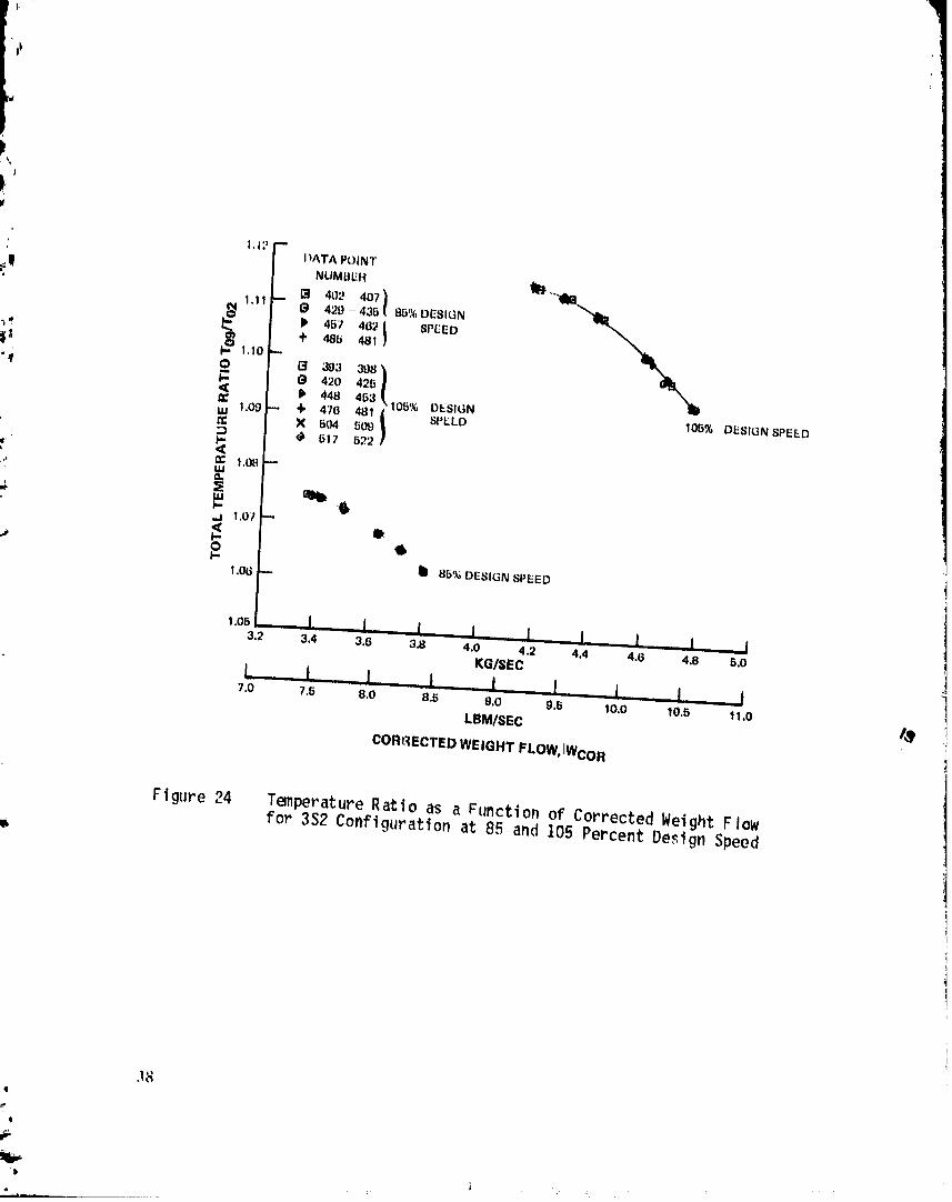
Figure24 TemperatureRatioas a Functionof CorrectedWeightFlowfor 3S2 Configurationat 85 and105 PercentDesignSpeed
3_4
e
.... "F } '--" _fFL" 1980014823TSp
O,B8
t:I o,.w
"i c,_u_
"_ DATAPOINTNUMeERS= 0.e2--
I _ (_ 543 -- 550," 552 -. 559
_ + .7o-.77Y 58O 5870.80 -- ,--589 - 506
i ,
_:) -- I I_ DESIGN POINT
0.78- _
,I
• 1.36
¢_ 1.34 _
_'_ 1.32
gI- 1.30 --<muJ 1.28 --
1.26
.J
1.24 '-'-
1.22
1.2o I I I I I3.8 4.0 4.2 4,4 4.6 4.8 B,O
KG/SEC
I...... 1 I.... I I I8.6 9.0 9,5 10,0 10,6 11.0
LBMISEC
CORP,ECTED WEIGHT FLOW, WCOR
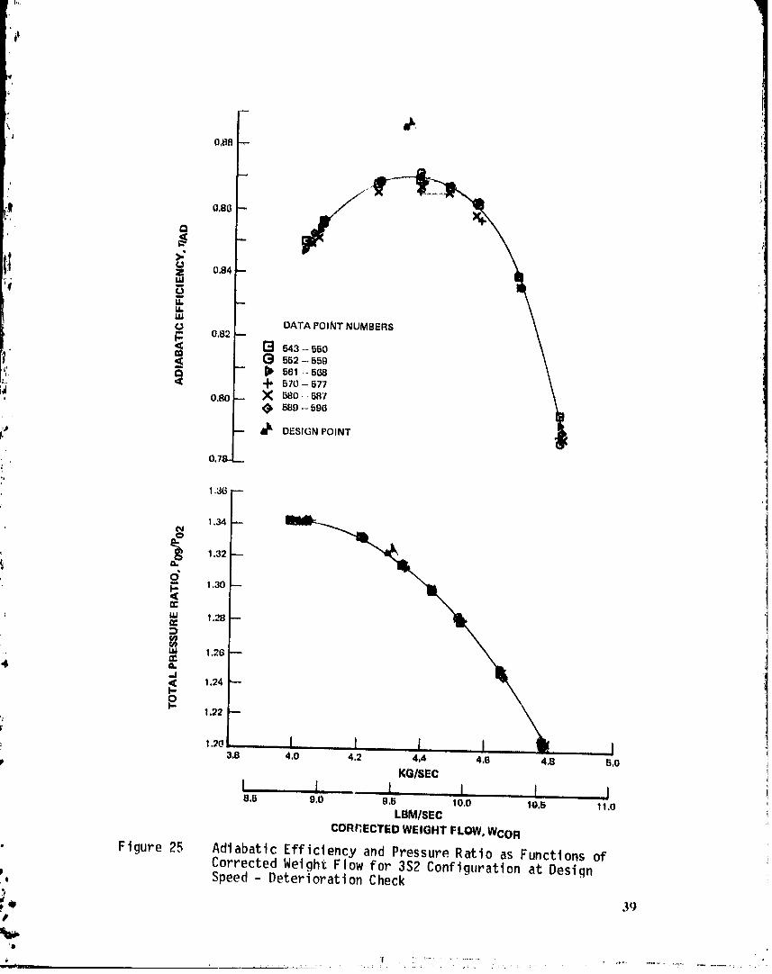
Figure25 AdiabaticEfficiencyand PressureRatioas FunctionsofCorrected Weight Flow for 3S2 Configuration at Design
P Speed- DeteriorationCheck,Q
•", 39_'°O
'1 ! . :. .................. ." ........ , .....
"" - 1980014823-TSD04

0.80
0.79
O,78
1.18 1.22 1.26 1.30 1.34 1.38 1.42
TOTAL PRESSURE RATIO. P0g/P02
Ffgure 26 Adiabatic Efficiency as a Function of Pressure Ratto for3S?Configuration at Design Speed - Deterioration Check
i¢.
Q
;.: 40
It 'i,.
,,. ,, ,,, .,,,
1980014823-TSD05

!
1,11 mDATA POINT NU=";.;E.R_;
_(_ fi43 _ 550
B61 - 568
! [_ "° i 5vo-_5.
t' I_ _o - 587
: _ 689 -. 596
' DESIGN POINT
, ,1,09
1.07 --
.06 I I I, I J I3.8 4,0 4.2 4.4 4.6 4.8 5,0
t .... I I KG/SEC I I t8,5 g.0 O.5 10.0 10.B 11.0
t
LBMISEC
CORRECTED WEIGHT FLOW, WCO R¢.
r=
: Figure 27 Temperature Ratio as a Function of Corrected Weight Flowfor 3S2 Configuration at Design Speed - Deterioration Check
!
41a_
.iv
' 1980014823-TSD06

t_, O,B6 --
i" "_ DATA PDINT NUMBER_. "_ 13 742 - 74BROTOR
0.82 j_'_ (_ 742 746 STAGESTAGE 1_ ,_ P 77S - 785 ROTOR
\ 4" 778 785 STAGE\ X SO6- S13 ROTOR
o,7B \ \ _, 6o8-slaSTAG_.-_,. ,, ,, ., ._,- _ ROTOR" STA"_"F\ _ \ . .Q-842STAGE
3 o,4 t _,.._'_ \ N .3-.870ROTOR '•,1 W\ - ",, \ .( 883-870STAGE
_-. "¢-$:_ \ t. \ M 8_l-.STRoTo."_ ""BI',,,11__ \\. _ II 891 "-"S97 81"AGE
oo \ %\0.66 STAGE 3 4=.
i _ 0.58o.84 ',
0.80 /' PREDICTED SURGE
0.46 ROTOR 1
_L 0.42
ROTOR3_ "', _._ \
o. ',,,Z %0.30 -" ,_
t
I 0.26 -- _
¢" { I 1 I l I Jl 1
. 0.22 ..... ,'0.20 0.24 0.28 0.32 0.36 0.40 0.44 0.48 O.52
P FLOW COEFFICIENT,
Figure28 PressureRiseCoefficientas a Functionof FlowCoefficientfor 3S1ConfigurationatDesignSpeed
o 42
'I _ ...'. . ".,., _ .

0.260.20 0.24 0.28 0.32 0.36 0.40 0.44 0.48 0.62
FLOWCOEFFICIENT,
Ftgure 29 Pressure Rise Coefficient as a Function of FlowCoefficientfor 3S2 ConfigurationatDesignSpeed
, 43
'-- I I
- 1980014823-TSD0

1
O.80 --. DATA POINT NUMBER
751 - 756 ROTOR751 - 75i_STAGE "_0,62 ,,.- b 7(_1-- 775 ROTOR _'X
,_ 769 -- 776,6TAGE797 -- 803 ROTOR
@ 797 -- 6o3 STAGE,0,76 '-- "t_ 627-833ROTOR
N 627-6338TAGE --._._ 8TAGEI,14m-\:q N 864 _, 060 ROTOR "_ | \
" 034 -- "< 654 " 660 STAGE sTAGE 2f_ f \x ==-.BROTOR_ .__.j \
nzo TESTDATA \ ""4,, \ "_ \
_. o.62- _
'" 8 0.54 _ '
_ o._o '_0.46
<
0.42 -- _ ROTOR2_n-
o: ROTOR 3 al_
1 '0.34 -- _ ROTOR I
_, ' ,0.30 -- _
O.26 -" \_
*' o.22 I , I I I I I I I0.20 0.24 0.28 0._ 0._ 0.4o 0.44 0.48 0..2
FLOW COEFFICIENT,
Figure 30 Pressure Rtse Coefficient as a Function of FlowCoefficient for 351 Configuration at b5 Percent DesignSpeed
o 44
_',
"l
1980014823-TSD09

Figure 31 PressureRise Coefficientas a Functionof F low
Coefficientfor 3S2 Configurationat 85 PercentDesignSpeed
(j 45iq
,#
_ 'D ,,
1980014823-TSD10


,
DATA POINT NUMBER13 393 - 39_ ROTOR
R _3 - _B _TA(3E,,. P ,I_0--'426 ROTOR
0.TFI_ '0'420 .-426 BTA(3(E"" 448 - 46;__IOTOR
_, .4 44B-453BTt_._F_ _TACIE I'@ 4713- 4B1 ROTOR
' 0.74 .,=. N 470- 481 6TAG_J I_ 604 - 001)ROTOR
..;| ,4:604 -=5gOSTAGE;,. _ 61?-622ROTOR
030 _ _ 617 -Q_,_ STAGE _ll.__,_ _l
.......OEBtLtN STAGE ;I _
!'' e .... TEST DATA
"' ,f O.60 -"
0.02 STAGE 3
o. =.,'), i
0.50
'- "_ 0,46_" ROTOR I
0.42 "-' <
ROTOR 3 ".
0.38 --
0,34
ROTOR 2
0.30 _ i
B
o_8 I I I I L L .... I J0.20 0.24 0.28 0.32 0.36 0.40 0.44 0.48 0.152
FLOW COEFFICIENT, @
Figure 33 PressureRise Coefficientas a Functionof FlowCoefficientfor 3S2 Configurationat 105 PercentDesignSpeed
'4 47
Q
"_ ...... - _ : - _ ,...-.!....,...{.,_ - _
'_'_""_ - - 1980014823-TSD1;

0 ,fl4
CONF,OUnAT_ON
"i i o,.20,78
d _,'I,oE
T-.o,.,.-t 1.350F
' J_ '
")'!) A0.0045 PR -_ "_0.01_AD
I_0O 20 40 60 80 100
HUB PERCENT SPAN TIP
Figure34 AdiabaticEfficiency,TemperatureRatio,and Pressure" Ratioas Functionsof PercentSpanfor 3SI and 3S2
Configurationsat PeakEfficiency;DesignSpeed_4
r,, 48f,
w_!!__- -Y " - 1980014823-TSD13

O,B(_
! i o,.2o,78
I_ o: 1,12o
T A0.0013TR _.A0,01qAD
,
1,3g0f
,.'I
--." 1=o1.370
,_ LU i_ ___ -
== T_o
1,340
1,3,30, 0 20 40 60 80 100
HUB PERCENT SPAN TIP
Figure 35 Adiabatic Efficiency, Tmperature Ratio, and PressureRatio as Functions of Percent Spanfop 3S1 and 3S2Configurations at Near Stall; Design Speed
49
1980014823-TSD14

2130 '- 1_,99r-,. CONFIGURATION
/ "'0" 3Sl'=='_=" 3B_,
, ZzI 2
ee
2110 ""I0,10
O 2100- 10,05p.,u,.I...I
2090I0.00 I"
I
_
B23
522 -- 290
=" p
B21
520 289
_1, _ 519
O_ .-- 288 --t-* 518
i _1_- 0;_8_ 1 I ...... I 1 I0 20 40 60 80 100
HUB PERCENT SPAN TIP
Figure 36 Inlet Total Pressure and Total Temperature as Functions ofPercent Span for' 3S1 and 3S2 Configurations at PeakEfficiency; Design Speed
50
_ ,'D'
L,, q ..... ...... "J'_
1980014823-TSEO]

F/
ILla. 289
b20 --
/
ulu - N
t-" _ ;288U.I bI8
; z !bl/- 1 1, I 0 I 1t) 20 40 t30 bO 1¢10
HUB PERCENT 8PAN TIP
'p Fl,_tlre37 Inlet Total Pressure and Total TL-,mperattire as Functions of• Percent Span for 351 and 3S2 Confiqurations at Near Surge;
L1esiqt_Spt,ed
";+ +_I
P l ...... .. ..
_,:,-_ ,...... _ 1980014823-TSE02

APPENDIXAI
SYMBOLSANDABBREVIATIONS
,, A Area, meters 2 (feet2)/ ASP AerodynamicSet Potnt (rtg speedand throttle setting)
_! b Chord, cm ( t n.)i'e .
D Diffusion factor' for rotor:, gOoo . , .vo3- r, o,....
(r2 + r3)(, v'efor sta_or:
:, D: 1- V4 + r3 Vo3" r4Vo 4i i i i| i
,_. V3 (r3 + r4) a V3
•":. E WorkCoefft ct ent
_.". E = U3 V_ 3 - U2 Vo 2
__ 1/2 U_
I6V Inlet Guide VaneN Rotor Speed, revolutions per mtoute _P Static Pressure (absolute), N/mz (lbf/ft z) .Po Total or Stagnation Pressure (absolute), N/m_ (lbf/ft 2)Pr Pressure Ratio._P Static PressureRise, N/m2 (lbf/ft 2)r Radius, cm(in.)s Blade spacing (circumferential), cm(in.)T Temperat ure, K (OF)Tr TemperatureRatioTo Total or Stagnation Temperature, K (OF)
: U Rotor tangential velocity, m/sec (ft/sec) ./eV Air Velocity, m/sac (ft/sec)W getght Flow, kg./sec (lbm/sec)
SpecificHeatRatio•_ _ Total Pressure/Standard Day Total Pressure
0 TotalTemperature/StandardDay TotalTemperatureEfflciency
c Solidity,b/sp Density, kg/m_ (lbm/ft3)
Stage Static Pressure Rise Coefficient,(See App, B)Stage Flow Coefficient, (See App. 6)
pp_GEDi_GipAGF,lbI_/_K _K)1 FILMED, 53q
"$
o
1980014823-TSEO3

' APPENDIXA (Cont'd)
Subscrttp._
ad Adlabatlc! an Annulus
av Averagecor Corrected to Standard Daym Mldspannora Nomlnal
'( z Axial Componento Tangentla'$Component0 Total or StagnatloncondltlonI Inlet Statlon2 First Rot.orInlet3 First Stator Inlet4 SecondRotor Inlet5 Second Stator Inlet6 Third Rotor Inlet
' 7 Third Stator Ir_let
i' g Exit Station.!
Superscripts
, Relativeto Rotor- Mass Averaged
t
4
W_54
1980014823-TSE04

APPENDIXB
Dk_TAREDUCTIONEQUATIONS
, DATACORRECTIONANI_-MASSAVERAGING
A]]. measurementswere corrected to the nomtnal test speedand NASAstandard sea level tnlet total pressure and temperature. Ext.t total.
/ temperature andpressure data at each radtus w,:re corrected ustng the-..! relationships:
2
/ 1' (1) TO - KT I + -
(massav)
7-I
2 _-1
, (2)Po"Kp i + ,P°',,_estLXeo,,nletI N'c.r:'t.
\ (massav)/
where, KT = 288,15K (518s69°R_Kp = 10,1325 X 10_ N/m£ (2118,22 lbf/ft 2)
Static pressures measuredat the inner andouter case walls werecorrected to ambient level using the relationship:
_ 7-1
Ptest 27 _.' Ptest _i "(3) P =Kp .......... +----Po, Inlet(mass av) _-1 _Po, tnlet)
'\ (massav)/
- / /• . nom -1Ptest Ncor,
_Po, t nlet Ncor. test\ (massav
m
where Machnumbersquared has been assumedsmall with respect to 1.0.The compressort nlet total pressure and temperature measurementsweremassaveragedradially and ctrcumferenttally for each test point inorder to obtain the reference values in equations (1), (2), and (3).Corrected test speed, defined by (N/_/_)2, was also obtained for eachpotnt.
II
q
_' -- _ , ..................... 1980014823-TSE(

'tt
The levels of Inlet total pressure and temperature measur.ementswere"_ adjusted so that the radial and ctrcumferent_a:l massaverages of all
readings are equal to the standard values,
(4) Po = Kp + Po " Po tn]et.-(mass av)
(5) To " KT + To " To inlet (massav)
The corrected test values for total temperature and total pressure from
jI! the pole rakes at the tnlet andextt stations were ctrcumferenttallyand radtally massaveragedto produceaverage values for calculating'_ overall performance. A linear static pressure gradient betweeninner
andouter cases at each circumferential locatton was usedfor the massaveraging. The corrected data were also massaveragedcircumferential lyat each radius to give composite radial distributions of temperatureand pressure at the tnlet andexit stations.
,,, CompressorOverall PerformanceComputations
Pressure Ratio
._ Since the tests were intended to reproduceconditions which would bepresent in the latter stages of a core compressor,the overallperformancewas presented from upstreamof the first rotor (station 2of Figure 1) to the extt station (station 9). The overall pressureratio basedon the tnlet to the first rotor wascalculated as follo_s¢
Fog _og 1
_02 P01 Fr,IGV x Fr,pole x Fr,strut "
where Tog = exitstationmass-averagedtotalpressure
P02 = firstrotorinletmass-averagedtotalpressure
P01 = inlet station mass-averagedtotal pressure
_r,IGV = totalpressure ratioacrossthe inletguidevane
• Pr,pole - total pressure ratio due to losses of inletstationand flowstationpolerakes
Pr,strut = totalpressureratiodue to inletstrutlosses
m 5(_
@
'b ._ .
1980014823-TSE06

All the inlet loss pressure ratios were calculated as functionsof theinlet dynamicpressurecalculatedas a functionof flow by:
For Wcor in kg/sec
Po " P
1.68_842x 10"3+ Wcor x (2.0B3418 x 10"3 Wcor - 1.455674x 10⁻³)
t:! PoFor Wcor tn lbm/sec
IPo " P
q -------= 1.68P842x 10"3+ Wcor x(4.28655x 10⁻⁴ Wcor - 6.602824x 10"4)Po
<o)ogr,IGV -"1.0 - 0.01534 p-
(o>• fir,pole= 1.0 - 0.035095 -.Po
gr,strut = 1.0 - 0.001455 .-Po
TemperatureRatio
Since no work is done ahead of the first rotor and heat loss throughthe cases is estimatedto be negligible,the total temperatureratio isunchanged:
E
To9
To2AdiabaticEfficiency
P The adiabaticefficiencyof the compressorwas calculatedby:
(Poq/Po?)_ -1.0'Iad
(To9/To_)-I.opC
,,, 57
'# i
L li
1980014823-TSE07

\#
'. where'_ _ the ratio of specificheats at the avera_.,..te_4_peratureofthe compressor.
Flow Rate
The flow rate was first calculated for the inlet flow calibration sta-tion (station O) and then corrected to the inlet of the first rotor
t_ (station 2). An ideal flow rate was calculated from the average mtdspzntotal pressure measured at the flow calibration station, the averagemtdspan static pressure at that station (obtained by linear Interpola-tion between outer and inner wall measurements), and the mass averagedtotal temperature from all the measurements at station 1. The actualflow rate was then the product of the ideal flow rate and the flow co-efft ctent. Thus
To1
W = (WIDEAL) x (Flow Coef.) KT
Rotor and Stage Performance Based on Wall Static Pressures I#
Rotor and stage performance was computedseparately for each of thethree stages for each test point in terms of a static pressure rise co-efficient and a flow coefficient. The static pressure rise coefficientis based on the kinetic energy the mtdspan flow would have if the airvelocity were the same as the rotor velocity. The rotor static pressurerise coefficients are:
4
P3 " P2
@ROTOR I i/2 O2 Urn22
P5 " P4qJROTOR 2
2_, I/2 O4 UreaI'o
g
,_F,'
1980014823-TSEC

P7 " P6==
v,Ro'ro_3 t/2 P6u2.m6
g
where P _ staticpressure,Nlm2 (Ibflft2)!
P = fluid density,Kg/m3 (lbm/ft3)g
Um. = midspanrotor speed,m/sec (ft/sec)
and subscriptsfor P, p, and Um correspondto stationnumbersinFigure 5.
.t Similarly,the stage static pressurerise coefficientsare.'
P4 " P2
i STAGElg
_;_ P6 " P4
_STAGE2 1/2P4u_g
P8 " P6
_] VJSTAGE3 i/2 P6 U 2m6
g t,_+
The flow coefficientusedfor both rotor and stage performanceis theratio of the axial velocityat the rotor inlet stationto the midspanrotor speed.
Vz2
= Um2
_" Vz4
(_2 =
Urn2
Q
•, 59
#
'o . i '
2-.._.,_;';..... II II ..................... , ..... ". ' ...... . .... ,,
1980014823-TSE09

Vz6
Urn6
,,;|,. In order to calculate the f'lutd denstty values, the pressures andtemperatures wttMn the compressor were calculated based on assumptionsof equal rotor pressure ratio and temperature ratto for each stage.
_ Stator losses were assumedequal to the design values for every testi pot nt.
P03 P05 P07
, 'o6 1t3
_: - P09/P01 -Wl M _ N - ...........
i* P02 P04 P06 P08_------ X _-----'- X =---'- X =--.-
_P01,DES PO3,DES PO5,DES POT,DES_
Tr, ROTOR Tr, STAGE\ioi/
/e
m
6OIt.ql
'D
#
._..... , " " 1980014823-TSE10

•i_
APPENDIXC
TABULATIONOF INLETAND EXIT SPANWISETEST DATA
le
f_''IP
1980014823-TS E11

b.
iF
mq,, 3SI CONFIGURATIONAT _5% DESIGH SPEED
ASP 8L1_588
ASP 8_ WCON• 3.87003 _q/_c (8,5320 ll_mt_nr)
' _ Span 5 I0 20 30 50 70 80 qO _fi
,...l Diam
:_. m O,SGOl 0,562Q 0,5679 (I,573_ 0,5_3fi 0,5940 O,fi@g_ 0,6044 0,6070ft 1,83// 1.84_3 I,_633 1.8_OG 1.9147 1,9488 1,96fi8 1.9030 1,091B
ro (I_lot)
i_ Nlm_ 100710 101257 101508 101575 I(31579 101550 101378 10074_ 100263_ Ibf/ft2 2103.39 EI14.81 2120.04 2121,45 )121,54 2120,92 2117.33 2104.1R 2094.04
'*# T°_tnl°t) 289,380 288.79¢,. 288,405 287,803 287,8_4 _87,528" 288,128 280,599 288,9_6oR 520.879 519,834 519.125 518.042 518.079 517.546 518,627 519.475 520.135
Pc (e_It)
_,/m2 i_1630 !22022 122390 122554 122708 I_2590 122407 121965 121750m" l_f/ft2 _540.30 _548.50 2556.19 2559.61 2562.83 2560.35 2556.53 2547.30 2542.81' To (exit)
307.448 307.328 307,080 306.871 30G,666 306.262 306.837 306.872 306.819o_ 553.402 553.186 552.739 552.363 551.995 552.157 552.303 552.366 552.270
_w, ASP 883 WCOR : 3.73667 kg/sec (8.2380Ibm/see)
% Span 5 10 20 30 50 70 80 90 95Diam
m 0.5601 0.5628 0.5679 0.5732 0.5836 0.5940 0.5992 0.6044 0.6070ft 1.8377 1.8463 1.8633 1.8805 1.9147 1.9488 1.9658 1.9830 1.9915
Po (lfflet) IN/m_ 100740 101270 101493 101559 101568 101535 101368 100749 100365lbf/ft2 _i04.02 2115.08 2119.73 2121.11 2121.30 2120.62 2117.13 2104.20 _096.17
T° IInlet) 289.355 288.812 288.365 287.806 287.818 287.538 288,135 288.610 289.009OR 520.835 519.857 519.052 518.047 518.069 517.564 518.639 519.493 520.212
Po (e_|t)
:_ N/m_ 123526 123981 124275 124407 124628 124437 124255 124115 123646Ibf/ft2 2579.90 2589.42 2595.55 2_98.30 2602.92 2598.93 2595.14 2592.22 2582.42
To (exit)
308.730 308.595 308.366 308.191 308.054 308.087 308.336 309.265 308.324O_ 555.710 555.458 555.055 55'1.739 554.493 554.552 555.000 554.873 554.978
62
4
it,
Q
1980014823-T8 E12

351 CONFIGURATIONAT 551 DESIGNSPEED(CeBt'd)
ASPBB4 WCOR" 3,_677 kgl_ec(B,03Q8Ibml_c)I
W Span 5 10 _0 30 _0 70 @0 90 96
Olam
. m 0,5601 0.56_@ 0,B679 0.673_ 0,5@36 0,5940 O.Bg9_ 0,6044 0,6070ft 1.0377 1,8463 1,6633 1.880B 1,9147 1,9400 1.96B8 1.9830 1,9915
_! Po (l_Iot)N/m_ 100774 101_50 101484 101640 101563 101520 101393 100756 100435lbflft2 2104.71 2115,04 2119,B4 2120,71 2121.00 _120,31 _:77.64 2104.34 2'97.65
TO (inlet)K 289,395 288,833 288,365 287,790 287,815 287.522 788,_08 288,631 _89,028
oR 520.905 519,895 519,052 510.034 5_.033 517.536 518.590 519.531 _20._46
Po _e_4t)
N/m_ 1_4546 125085 125391 125482 125709 125528 135370 17533! 1P47_2lbf/ft2 2b03,29 2612.47 2618.86 2620.77 2625.51 2821o72 2G18.43 2617.61 _505.52
TO (exit)K 309.574 309.373 309.212 308.937 309.954 308.749 309.300 309.]49 309.299
oR 557.229 556.867 556.578 556.083 556.130 556,103 756,735 556.4_3 556.734
ASP885 WCOR = 3.56159 kg/se¢ (7.8520 lbm/sec)
_ % Span 5 10 20 30 50 70 80 O0 95Oiam
m 0.5601 0.5628 0.5679 0.5732 0.5836 0.5940 0._9P2 0.6044 0.6070ft 1.8377 1.8463 1.8633 1.8805 1.9147 1.9498 1.9658 1.9830 1.9915
Po (t_let)Nlm_ 100788 101261 101475 101534 101542 101514 101371 100821 100467lbf/ft_ 2105.02 2114.90 2119.36 2120.59 2120.76 2120.17 2117.18 2105.70 2098.30
To (inlet)
K 289.396 2_._2 288.357 287.836 287.768 286.433 288.120 288.618 289.013OR 520.908 519o948 519.038 518.100 517.979 515.575 518°511 5!9.508 _20.219
Po (e_tt)
N/m_ 125528 125974 126272 126330 126480 126408 126309 126279 125736 2_lbf/ft2 2621.72 2631.03 2637.26 2638.47 2641.60 2640.09 2639.04 2637,40 2626.07
TO (extt)K 310.235 310.007 309.917 309.609 309.586 309.710 310.039 309.871 310.0dl
oR 558.419 558.008 557.846 557.291 557.430 557.473 558.056 557.764 558.070
63
6
"j=.If i , '
1980014823-TS E13

#$
3S! CONFIGURATIONAT _5_ DESIGN SPEED (Cnnt'd)
ASP _B_ Neon " 3.417_0 kgl_c (7,G3_0 l_l_ec)
_p_n 5 10 _0 30 _0 70 gO qO gfl
Oi_mm O,fi601 U,56_8 0.6670 0.573_ 0.5A3_ 0,5_40 O,fi_O? 0,6044 0,6070
4 ft 1,Q377 I.B4_3 1,@_33 |.BQO_ hP147 1.94B8 _,O_GO I,P_30 ],9glB
N/m_ _ 100826 101_65 101401 IOlS_O 101S_9 1014q7 101387 100831 I005R6Ibf/ft. 2105,81 _114.98 _119,06 21_0,30 _1_0,49 _11g,03 _117.52 _10_.9_ 2099,_
To_tnlot) 289,453 288.873 286,367 287,7_7 _87,786 _87,506 288,111 208,69_ _09,07_
i# o_ 521.011 519.967 519.056 618.012 @18.011 _17,B04 BIB,lOG 519,B6P B20.332
Po (o_It)N/mK 126627 127095 127290 127411 I_7383 127580 127420 127401 126939lbf/ftg _644.6_ 2654.45 2658,53 2661.04 _650.47 _64,58 2_G1,24 _6b0.85 2651.19
TO (extt)K 311.23_ 310.937 310.946 310.64_ 310.747 310.810 311.10_ 310,945 311.116
oR 560.;13 559,682 559.698 559.158 559.34l 559.464 55V.986 559.697 560,005
ASP 887 WCOR= 3.22398 kgtsec (7.1017 lbm/sec)
Span 5 10 20 30 50 70 _0 _0 q5
Olamm O.S_OI 0.5628 0.5679 0.5732 0.5836 0.5940 0.59o2 _._44 0.6070ft 1.8377 1.8463 1.8633 1.8805 1.91_7 1.9488 1.9658 1.9_30 1.9o15
Po (l_let)N/m_ 100906 101259 101452 101497 i0150(_ 101463 101377 100907 I00628Ibf/ft2 2107.48 2114.85 2118.89 2119.61 2120.00 2119.11 2117.32 2107.50 2101.68
To (inlet)K 289,298 288.719 288,285 287,783 287.763 287,603 288.180 288,737 289,153
OR 520.733 519.690 518.909 518.005 517.969 517.682 519.720 519.722 520.471
Po(e#t)N/m_ 127333 127677 127883 127996 127980 128097 128044 127868 127636lbf/ft 2 2659,42 2666,60 2670,90 2673.27 2672.94 2675,37 2674,27 2670,60 2665,75
To (exit)K 311.690 311.499 311.660 311.435 311.614 311.646 311.902 311.725 311.800OR 5bi.037 560.694 560.983 560.578 560.901 560.958 561.419 561.101 56!.235
64h_
r_._
1980014823-TS E14

3S1 CONFIGURATIONAT 85_ DESX_NSPEED(Cont_d)
ASP 8_8 WCOR , 3,13BgB kg/sec (6,g203 lbmt_ec)
Span 5 lO gO 30 BO 70 80 90 95Olam
m 0.5601 0.G628 0,6679 0.G73_ 0,6836 0.6940 O°Sgg2 0.6044 0.6070ft 1.6317 1,8463 1,@633 1,0805 1,9141 1.9408 I.fl653 1.9830 1.9915
Po (tQlot)
!_ Ntm_ 100921 10127? 101443 101485 101497 101406 101366 100921 100683
lbf/ft2 2107.78 2115.22 2118.70 2119,58 2119.82 2119.18 2117.0_ 2107.79 2102.19
Yo _tnle¢) 289.349 288.761 2_,312 287.811 287.773 _87.592 288.130 288.685 289.090;_ oR 520.824-G,t9.765 518.950 518.056 617.987 517.661 518,629 519.628 520.357
Po(e_tt)N/mZ 127643 127908 128123 128192 128207 128309 128271 12_091 ]27881lbf/ft 2 2_65.90 2671.43 2676.96 2677.35 2677.67 2679.80 2615,26 2679.01 2670.87
To (exit)K 312.201 312.120 312.239 312.029 312.227 312.22G 312.49_ 312.340 312.447
OR 562.101 561.811 562.025 561.648 562.004 562.002 562.486 562.208 5_2.400
65
i";e
198001482:3-TSF01
),
i_
.ISI Ff)NFIGIIRA1I(1N AT ILI0%IIITSTtINSPEll1
ASP _ffi3..It7()
ASP flb3 WCOR _ 4.5q/;' k!l/!;oc (ILl. 1_(!_;' lbm/_m:)p
.Sp,tl| 5 10 ;_0 30 !it) /0 110 Oil 9!1l) I am
' m U,5601 0, fi(i?.8 O,507q (1.fi/.I;_ ¢1,N_3(_ (1.._q4(I O, b.q!l;' 0.6044 (I, fi(170ft I.fl3ll I._,14t_3I.H63J ).HH05 I..o147 I.q4fl8 I.n65,q I.._830 I.Oql5
Pt_ ( t rlh:t. )
N/m,. 1(.)04;'2 1011H3 IOI 5/q ] O](,8:1 101697 1011H,,I 101;¢7q I (l(1_?0 4mtf.;8i 1(It,/t't 2 _tlgl.37 ,qI3.77 ','1;11.5,1 .'1;'3.71 21;'4.00 i)i;'3, ll :'117.3!I ;'(lO9.(i1 ', ,- r.035..,q
To (inlet)
K 28g.778 289.0,1/ 28q.510 ',?_1.751 ,"dl.71,.' ','15'.330 "_.,&l.0._8 288. 647 _8o.168°R 5;1.596 ._.0.281 519.314 511.thlg 517._77 517.190 518.500 51,).560520.40o
Po (exlt)
N/m_2 I;19(_/0 130334 13084q 1311)5(_131;'1_4 131001 1301U8 130314 12110,19lbf/ft ;_ 210i1.35 ,.7"...." 10 _73,.,_._'' ' 2737.18 ;'/41.31 Z736.03 ,n73o ,_ 2721.68 2'716.)6
To (exit)
_' K 314.7qI J14.563 314.;'1/313.g;23 313.b.13 I13.708 313.q54 314.043 313.986" °M 560°620 556.208 565°586 N_5.056 564.553 NN.831 565.113 565.273 565.171
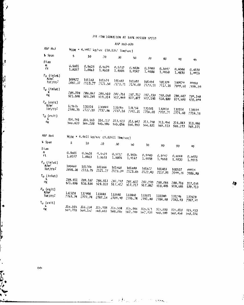
ASP 8o,1 WCOR " 4.,Itilikg/soc (9.83511 It,m/see)
% Span 5 10 _)0 .70 50 70 80 90 oF[.] t dill
m O.5501 O.bo28 it.5q79 0.573/ O.5835 O.5o,10 t).5eO_ l).6,14,1 0.(,070ft 1. (7377 1. 8463 1. 8033 1.11805 1. 9147 1. g,lil8 I. o658 1.9fl30 I..o915
Po (,filet)
N/m2 100469 101;106 101566 105_68 101{_80 101622 101403 100537 9q.Ol_lbflft;2 2098.36 2113.75 .I_I._7'" " 2123.3o .7123.65 2122.43 3117.85 20.)o.7(_2086.fl0
TO (inlet)
K 289.911 289.18/ 288.513 C87.737 _ "*,-
• _81.b_ _" I_J7.270 ?&%055 288.716 317.0._ 1,_
OR 521.836 520.534 519.319 511.92; 517.717 517.082 518.495 519.685 570.713 .Po (e_It)
N/m;? 13;2328 13;7998 133,148 133580 133860 133671 133340 133;205 1325_8 .]lbflft; ?763.74 2777.7,l ;2781.14211_9.90 2795.74 2791.80 ;)784.88 ;783.03 7767._)I i
To (exit) ]31u.545 316..:U4 315.938 31,1594 315.4,1¢_315.511 :US._HO 315.810 U5.933oK 560.778 559.11,;)b6_l.,,q3568.0,]b 567./q9 b57.934 h6,q.580[;b(1.45,15:i((._74
(i(i/,V
4,
1980014823-TSF02

• ]al_ ,ISI CONFIGIJt_AT|ONAT 10_ [%FSIGNSPEED (Coot 'd)
ASPtt¢ib WVOR • 4,301i5b ktl/_ec(_,b_66611_nl_ec)
Span b 10 _0 30 bO 70 80 oO q_Diam '
w, O. _bO| O,._ti_B O,B67g O,_._73,_O,_[136 0,5940 O,fi997. (I,6044 0,0{110ft 1.lt377 1.t146J 1.8633 1. H_05 I 9147 1. 948[I 1.e658 1.q830 1. qql._
i_" I Po (tqlet)N/m;, 100501 101216 101556 101660 101667 101611 lOl3,qg 10(1531 _,N84lbf/ft_ 2099.01 .?113.95 _1_1.06 21_3._ ;_1_3.38 _1_.20 _117,79 ;?099.65 _088._3
To (t,let)
q_ K ?e19,_5_eq.t_ _t_.515 _n7.710 _87.515 _87._m _ee.n41 ;ee.754 ,_17.155O_ 5_1._8 ,_0.553 519.322 517.874 517.702 516.PP6 518.460 51:1,771 570._94
'¢ Po (eXit)
N/m_., 1339_9_ 134576 135015 135099 135311 13,_;_1 13490? 1348_:! I34P00ll_f/ft_ ,.IJt.19 _,q[0.70 _!819.87 " ",8,1.6,. 28?6,05 28_4.7!I _819,39 2817o0,q i?_07.._,_
._. To (exit)
K 317.685 317._71 317.109 316.63_ 316.650 .117.147 316.975 317._11°R 571.t]28 571 t_J 570.793 569.933 569.966 316,710570.074 '_70.860 570.551 570.975
ASP 3bb WCOX• 4.','_008 k9/sec (9.43603 ll_lsec)
_an b I0 20 30 50 70 80 oO 95' _" Oiam
m 0.._601 0.5(,,__ O.5679 0.573? ¢1.5836 U. 5940 O. 59_,_2 O.6044 O.6070ft 1.c1377 1.8463 I.,'1633 1.8805 1.9147 1.9488 1.965_ 1.9830 1.:1915
Po (i!]Iet)
N/m_ 100541 101;730 101540 I0164_3 I011_53 101594 101384 100587 100040lbf/t'tJ "OY9.&_ ;_114.35 _I_0."" 7,_ "_,_ oo .'1_3.08 _ ".......... _1,1.84 3117.47 ;7100.81 208_.39
1o [|nlet)'I (
K ..81.975 289.179 288.516 287.690 ;787.627 787.216 _88.083 _88.761 _'89.406oR 5_1.950 5.70.518 519.3_4 517.837 511,7_4 516,_5 518.510 519.766 5,0.¢,_7"'_
Po (e_it)
N/m_ 13515_ 13515;. 136194 13b,9,'_" 136370 136449 136758 136057 135529lbf/ft_ _?B_?.7;_ _835.95 2844.49 21146.54 P848.17 2t_4_.81 " ",,845.8, 2841.63 2830.59
To(exit) .,
K 318.605 318.0_17 3,?0.839 317.494 317.6_:6 317.66_ 318.105 317._9,_ 318.186 1oR 573.484 57?.570 577.506 571.484 571.727 571 7_ '" ,_., 4,,• 5,_.585 ..... _, 572.730
07
I
I
] 980014823-TSF03

3S1CONFIGURAT|ONAT 10(_ DESTGNSPEED(Cont'd)
ASP86? WCOR• 4.14178 kg/sec (9,13111 ll_/svc)
Span G 10 20 30 50 70 AO 90 96Otam
m 0.5601 0.5028 0.5679 0.5732 0.5836 0.5940 0.5992 0,5044 0.6070ft 1.8377 1.8463 i.a533 1.8805 1.9147 1.9488 1.9658 1.9830 1.9915
it PO(t918t)
N/m_ 100598 101226 101638 101621 101630 101576 101391 1006i4 I00141lbf/ft 2 2101.04 2114.16 2120.67 2122.41 2122.60 2121.47 2117.61 2101.37 2091.49
T°_fnlet) 290.033 289.261 288.491 287.698 287.590 287.206 288.023 288,804 289.436oR 522.056 520.665 519.280 517.852 517.657 516.966 518.438 519.843 520.981
Po (extt)
N/m_ 13662q 137239 137536 137730 137650 137931 ?37695 137504 137071 Ilbf/ftZ 2853.58 2866.31 2872.52 2876.56 2874.89'2880.76 2875.84 2871.85 2862.81 ,
TO (extt) i
K 319.783 319.258 319.350 318.798 318.911 318.941 319.330 319.115 319.371°R 575.605 574.659 574.825 573.832 574.035 574.089 574.790 574.402 574.864
ASP868 NCOR• 3.95810 kg/sec (8.72617 ll_n/sec)
Z Span 5 10 20 30 50 70 80 90 95Dram
m 0.5601 0.5628 0.5679 0.5732 0.5836 0;5940 0.5992 0.6044 0.6070ft 1.8377 1.8463 1.8633 1.8805 1.9147 1.9488 1.96E8 1.9830 1.9915
Po(_let)
N/m_ 100626 101237 101518 101599 101606 101552 101364 100695 100227lbf/ft2 2102.63 2114,38 2120.25 2121.95 2122.10 2120.97 2117.05 2103.07 2093.30
To (tnlet)
K 290.073 289.167 288.580 287.656 287.616 287.187 288.n50" 288.757 289.417°R 522.I27 520.496 519,440 517.777 517.705 516.933 518.485 519,777 520.947
Po (e_tt)
N/mr 138002 138441 138741 138884 138836 138965 138910 138592 138354lbf/ft2 2882.24 2891.42 2897.68 2900.67 2899.67 2902.35 2901.22 2894.56 2880.59
To (extt)
K 320.805 320.441 320.58I 320.138 320,316 320.214 320.611 320,370 320.594OR 577.444 57b.790 577.042 575.243 576.565 576.381 577.096 576.661 577.065
;4
68d
1980014823-TSF04

i,
351 CONFIGURATIONAT 100%DESIGNSPEED(Cont'd)
ASP_9 WCOR• 3.72177 kg/sec (8.20915 lbm/s_c)
Span 5 I0 _0 30 50 70 eO gO 95Olam
m 0.5001 0.6628 0.5679 0.573_ 0,5836 0._40 0,5992 0._044 0.6070' ft 1,_77 1.,9463 1.8633 1.G805 1.9147 1.9488 1.9658 1.9830 1.9g16
Po (tiller)
N/m? 100727 101270 101497 ]01565 101575 101522 101353 ]00778 100353lbf/ft 2 2103.73 2115.08 2119.81 2121.25 2121.45 2120.35 2116.81 2104.8I 2098.93
To (inlet)
K 290.104 289.217 288.518 287.717 287.592 287.189 288.02I 288.74_ 317.213°R 522.103 520.587 519.328 517,886 517,661 516.P36 518.434 519.731 570,979
Po (exit)
N/m_ 138642 139065 139341 ]39434 139569 139561 139_47 13_28q 139141lbf/ft2 2895.62 _L_4.45"'2910.21 2912.15 2914.98 2914.81 2916.50 2909.12 ?g05.04
To (exlt)
K 321.770 321.553 321.743 32].403 321.731 321.527 321.934 321.674 321.872oR 579.181 578.791 579.132 578.521 579.112 578.744 579.477 579.008 579.365
ASP 870 WCOR = 3.59742kg/sec(7.93099Ibm/sec)
% Span 5 I0 20 30 50 70 80 QO 95Dlam
m 0.5601 0.9628 0.5679 0.5732 0.5836 0.5940 0.59e2 0.6044 0.6070ft 1.8377 1.8463 1.8633 1.8805 ].q147 1.9488 1.9658 1.q830 1.9915Po (iglet)
N/m_ 100776 101248 101481 101545 101553 101509 101373 100715 I00_45lbf/ft_ 2104.77 2114.63 _11..49"n 2120.83 2]20.99 2120.07 2117.23 2103.48 2097.85
To (inlet)
K 290.187 289.298 288.525 287.743 287.517 287.143 288.026 288.765 289.507OR 522.333 520.732 519.341 517.933 517.526 516.853 518.443 5t9.772 52].109
PO(exit)
N/m_ 138797 134456 139477 139618 139780 139784 139868 139549 139386lbf/ft? 2898.85 2808.18 2913.05 2915.99 2919.39 2919.47 2921.22 29]4.56 2911.1_
To (exit)
K 322.351 322.152 322.403 321.471 322.517 322.348 322.758 322.505 322.738OR 580.227 579.869 580.321 578.644 580.526 580.222 580.960 580.504 580.923
(_
tl'i
1980014823-TSF05

iI
JSt CONFIGUHATIONAT 105% DESIGNSPEED
ASP 87_-87q
ASP87_ WCON• 4,96/08 kg/soc (10.9506 lbm/sec)
% Span 5 I0 20 30 50 70 80 gO P5Olam
m 0.560! 0.5628 0.5679 0,5732 0.5836 N.Bg40 0,59g_ 0.6044 0.6070| ft 1,8377 1.8463 1,8633 1.9805 1.9147 1.9488 1.965B 1.9830 1,9915
Po(t_1ot)N/m( 100237 I01]33 101625 ]01767 101771 101699 101425 100330 99599
lbf/ft2 2093.51 2112.71 2122.50 2125.46 2125.54 2124.04 2118.3l 2095.45 2080.18 iTo (inlet)
K 289.895 289.[29 288.565 287.688 287.704 287.242 288.052 288.688 289.249°R 521.807 520.429 519.412 517.834 517.863 517.032 5Z8.490 519.636 520.644%
Po(exit)
N/m2 128771 129352 130073 130360 13068q 130324 X30144 12q342 129094Ibf/ft2 2089.45 Z701.59 2716.64 2722.63 2729.5! 2721.89 2718.13 2701.37 2695.98
To (exlt)
K 31_.149 314.924 314.576 313.644 313.977 314.15_ 314.146 3!4.241 3t4.077:"i oR 567.265 566.859 566.228 564.556 565.155 565.483 565.458 565.629 565.335
ASP 873 WCOR • 4,82112 kg/sec (10.6288Ibm/sec)
_;_ % Span 5 10 20 30 50 70 80 90 95Diam
m 0.5601 0.5628 0.5679 0.5732 0.5836 0.5940 0.5992 0.6,144 0.5070ft 1.8377 1.8463 1.8633 1.8805 1.9147 1.9488 1.9658 1.9830 1.9915
Po (i_let)
N/m= 100315 101167 101610 101734 101744 101565 101427 100391 99596lbf/ft2 2095.13 2112.92 2122.18 2124.76 2124.97 2123.32 2118.35 2096.72 2082.20
f o (inlet)
K 289.986 289.133 288.567 281.535 281.679 287.199 288.076 288.745 289.363oR 521.970 520.434 519.417 517.740 517.818 516.953 518.533 51o.736 520.849
Po (exlt)
N/m_ 133074 133804 134381 134557 134822 134572 134199 133964 133349Ibf/ft2 2779.33 2794.58 2806.63 2810.30 2815.83 2810.61 2802.82 2797.91 2785.07
To (exit)
K 317.103 317.444 317.007 315.742 316.431 316.637 316.853 316.941 3!6.n17OR 571.861 571.394 570.609 570.131 569.570 569.942 570.330 570.480 570.447
,IL
70 ::4• i
%_-._
"lb
..... ,_''t '_2:
1980014823-TSF06

351 CONFIGURATIONAT 105% {_FSIGNSPFEil(Cent'd)
ASP _/,l WC_)R" 4.68711bk.q/sec(10.3240lbm/s_c)
% Span 5 10 20 30 50 lO ,qO nO 95Diam
m O.5601 O.5628 O.567g O.8732 O.8836 O.ra._40 ().59q_ (l.6044 O.6070,| ft 1.8377 1.8463 1.8633 1.8805 1.9147 I.g4P,q 1.0658 I.n_130 I.qgl._
Po (i_1(,t)
N/m_ 100382 101188 101591 101708 101717 10164] 101434 100440 Qn16elbf/ft_ 20_6,52 2113,38 2121,78 21_4,23 2124,43 7122,82 21t',l,51 _0q7,77 2083,7._
To (inlet)
290.031 _8g.162 288.581 287.615 287.665 287.1.o0 288.071 _88.743 28q.392_# o_ fi22.056 520.486 519.44! 517.703 517.792 516.g37 518.524 51_).733 570.n01
Po (exit)
N/m_ 135_79 136703 137_08 137327 ]37584 137525 I_7068 1.170aO 1361n2lbf/ft;) 2840.00 2_t_5.11 _865.68 28;i8.16 2873.51 _,.87,.."28 _8;_2.73 ?Rr_?.31 2844.44
To (exit)
K 319.509 319.135 318.359 318.43,1 318.382 318.480 3|8.n31 318.767 319.010r'i °R 575.112 574.438 573..q4_ 573.176 573.083 573.259 574 071 573 77(; 57a.213' .
ASP ;375 WCOR = 4.SgOJ7 kg/sec (10.1201 lbm/sec)@
% Span 5 I0 20 30 50 70 80 QO 95Diam
m O.5601 O.5628 O.5679 O.573;2 O.5836 O.5940 O.590;; O.60a4 O.6070ft l._JJl7 i.8463 1.8633 I.8(_05 1.9147 1.9.188 l.n(;58 !.9830 1.9915
Po (inlet)
N/m_ 100405 101166 101581 101700 101703 101631 101423 ]00a58 Qg880Ibf/ft2 2.097.01 2112.90 2121.56 2124.o8 2124.13 3122.62 3118.27 ZOq.q.]3 _'o,q_.05
To {inlet)
K ?_0.052 289.230 288.525 ;_8/.634287.601 287.199 288.055 288.812 289.462OR
5g_.U_ 5_.0.610 519 141 517.737 517.677 516.954 518.513 519.856 521.028
PO (exit) I_p
N/m:' 137588 138309 138785 138883 139034 13_19K7 13_1756 138620 137r24lbf/ft2 2873.60 2888.65 2898.61 2.o00.64 2903.81 2905.11 2897.99 2805.15 2P)80.61
To (exit)
K 320.754 320.252 320.095 319.548 319.614 319.696 32(l.175 319.953 320.280OR 577.353 57_.449 576.166 575.181 575.300 575.440 576.311 575.911 576.5004k
Wl
;' 71
,#
1980014823-TSF07

t_
3S1CONrIGURATIOtl AT 105¢ DESIGP__PEED (Cont'd)
ASP 87o WCOH . 4,493_9 kg/_Pc (9._7_ Ibm/sot)
% Span 5 10 20 30 50 70 80 90 9B
•, Diam im 0,5601 0.5628 0,5679 0,5732 0,5836 0,5940 0,59q2 0,6044 0,6070
j ft 1,8377 1,8463 1.8633 1.8805 1,9147 1,9488 _.0658 1.9830 1,9915
Po (i_let)N/m_ . 100452 101183 101553 101676 101675 101627 101434 100533 _9928lbf/ft ( 2098.00 2113.27 2120.99 2123.56 2123.54 2122.53 211R,51 _099.68 2087.0fi
TO (In]or)K 290.065 289.265 288.483 287,663 287,558 287.199 28B.OBfi 288,84] _R9,520
q OR 522.113 520.673 519.256 517.7q0 517,600 516.954 518.496 519.a09 521.132
Po (exlt)N/m_ 138974 139700 140106 140242 140254 140460 140173 140012 _30399Ibf/ft2 2902.54 2917.72 2926.20 2929.03 2929.28 2933.58 2Q27.58 2q24.23 2911.41
TO (exit)K 3_i.856 321.264 321,254 320.023 320.789 320.866 321.298 32].079 321.388
oR 579.336 578.270 578.252 576.037 577.416 577.555 578.331 577.937 578.488
ASP 877 WCOR = 4.30493kg/sec (9.4908Ibm/sec)D
% Span 5 10 20 30 50 70 80 90 a5
Diamm 0.5601 0.5628 05679 0.573E 0.5836 0.5940 0.5992 0.6044 0.6070ft 1.3377 1.8463 1.8633 1.8805 1.9147 1.94S8 1.9658 I.Q830 I.q915
Po (inleL)N/m_ IU0544 101197 101546 101647 101658 _01590 101402 100585 100040Ibf/ft2 2099.92 2113.56 2120.85 2122.95 _123.18 2121.76 2117.84 2100.78 2089.40
TO (inlet)K 290.144 289.274 288.519 287.661 287.581 287.142 288.023 288.816 289.526OR 522.255 520.689 519.330 517.785 517.642 516.851 518.438 519.855 521.143
Po (exlt)N/m_ 141073 141688 141965 142193 142085 142393 142136 141987 141479 L_Ibf/ft2 2946.39 2959.23 2965.01 2969.78 2967.53 2973.96 2968.59 2065.48 2954.85
TO (exit)K 323.393 322.816 323.007 322.409 322.634 322.561 323.034 _9_.753 323.012oR 582.103 581.065 581.408 580.331 580.736 580.605 581.439 580.950 581.417
_' 72
1980014823-TSF08

351 CONFIGURATIONAT 10_ DESIGN SPFED(Cont'd)
ASP 878 WCOR • 4.0744_ kg/_ec (_,_827 lbm/_)c)
% Span 5 10 20 30 50 70 30 O0 P5Otam
| m 0,5601 0,562U 0,567g 0,6732 0.5836 0.5P40 0,59g2 0,_044 0.6070ft 1.8377 1,8463 1.8633 1.BB05 1.q147 1.946_ 1.9658 ].nR30 I.qPlB
Po (t_let)N/m_ 100510 101222 101512 101610 101620 lOlS_O I(11410 100657 100216lbf/ft2 2101.08 2114.08 2120.13 2122.17 2122.38 2121.14 2118.01 210_,_7 20o3.06
To(tnlet)K _90.192 _8g.276 288.486 287.662 287.536 ;87.12_ _8.077 79P.82_ 389._1_
OR 522.342 520.692 519.270 517.787 517.561 516.822 518.534 51Oo988 521.205
J Po (e_tt)
l N/m_ 142454 142927 143271 143359 1.13450 143_07 1.:3_07 _43]_0 142_18lbf/ft2 2_75.22 2985.10 2992.30 2994.13 _996.04 2997.23 _9,_7.27 2900.39 39R,I.79
,, TO (exit)
K 324.5_8 324.280 324.4_8 32_.O_H 324._97 724._6F 3_4.571 324,344 324.552oR 584.218 583.699 583,9_5 583.281 583.730 583.4_4 5_4.224 5_3.814 584.189
;._, ASP 679 WCOM _ 3.89543 kg/sec (8.5880Ibm/sec)
% Span 5 10 20 30 50 70 90 90 95
Diam
m 0.5601 O.5628 O.5679 0.5732 O.5_3_ 0.5_40 O.59_2 O.(_044 O.6070ft 1.83/7 1.8463 1.3633 1.8805 1.9147 1.9488 1.7658 1.983n 1.9915
Po (inlet)
N/m_ 100659 101234 101512 101586 101602 101549 101373 I0371r_ I002(_4lbf/ft2 2107..31 2114.32 2120.14 2121.58 2122.01 21_0..1"_ 2117.23 2103.50 2094.06
TO (inlet)
2g0.333 289.422 288.507 287.688 287.451 287.059 288.051 288.845 289.703_"J °RK 522.597 520.955 519.308 517.835 517.408 516.702 518.48R 519.o16 5_1.45.0
Po (e_xit)
N/m_ 142795 143267 143585 14360,3 143893 143918 143947 ]43_54 ]._-3384Ibf/ft2 2982.36 2992.21 2998,85 3001.10 3005.28 3005.80 3006.42 3000.30 2o94._6
TO (exit)
K 325.398 325.137 325.373 325.029 325.364 325.201 325.589 325.352 32_.S_ 1!_1t, nR ,'_R '_'1'1 _8" 2'12 _ _,:_ coo.n l? _o_ ._;,_ n.R_.357 586.05'3 _P_; .".47 r_._._,N17
' ' 73
1980014823-TSF09

352CONFIGURATIONAT 86% DESIGtlSPEED
ASP 457._62
ASP457 WCON. 3,783? kg/_ec (B,3406 lbm/_ec)
Span 5 10 20 30 GO 70 _0 90 g_Oiam
m 0.5601 0.56?8 0,567_ 0.5732 0.5036 0.5940 O,5_g? 0,6044 0,6070ft 1.8377 1.8463 1,8633 1.8806 I,g147 1.9408 1,96_8 1,9830 1.9918Po (iQlet)
N/m_ 10U849 101311 101616 101628 101616 1016,18 101084 100689 1ono81lbf/ft? 2106.29 211_.94 2122,30 2122.56 2122,31 2120.88 2111,20 2102.08 20Q0.24
To (inlot)
K 289.109 288.811 288.098 287.309 287.7?5 287.833 298.147 288.841 288.n79oR 5_0.397 519.859 518.576 518.056 517.905 518.100 51R,_65 519,913 5PO.la2
Pn (e_tt)
N/mZ 120993 121344 121064 121693 121976 121734 121390 121120 120729lbf/ft2 25_7,002534.34 2541.02 2541.62 2547.53 2_42.48 2535,30 2529.052F21,46
': To (exit)
307.379 307.076 306.595 306.126 305.512 305.789 305.022 306.Z31 305.147o_ 553.283 552.736 551.871 551.026 549.921 550.420 550.839 55!.215 551.065
b
ASP458 WCOR= 3.7144kg/sec(8.1890Ibm/sec)
¼ Span 5 10 20 30 50 70 80 90 95Diam
m 0.5601 0.5628 0.5679 0.5732 0.5936 0.5940 0.5992 0.6044 0.6070 1ft 1.8377 1.8463 1.8633 1.8805 1.91,171.9488 1.9658 1,9830 1,991_
Po(inlet)
N/mc 100858 101275 101605 101614 101505 101566 101103 100"I? lOOl2blbf/ft2 2106.48 2115.19 2122.072122.27 2122.07 2121.05 2111.60 ;!03.442091.19
To (inlet)
K 289,108 288,864 288,046 207,810 267.696287.824 298.]55 288,891 289.04_ #_OR 520,394 519,956 518,483 518.074 517.853 51_.0_4 518.67q520.003 520,282Po (e_It)
N/m_ 122151 122481 122782 122891 1231_5 127870 122G_5 122313 122073Ibf/ft2 2551.20 2558.08 2564.37 2566.64 2572.26 2566,202561_3 2554._8 2548.51
To (exit)
K 308,240 307,955 307,454 306,958306._n? !06.60930;._e8 307.:k3 3U/.055¢ oQ _=_.820 534,319 553.415 552,524 551343 552.05_5_2.a!6 b53.07,1552.717
•. _v
i
"; 74
,#
] 980014823-TSF] 0

ASP 460 WCOR - 3.4958 kg/sec (7.7070 l_/sec)
Snan 5 10 20 30 50 70 80 QO 95
Otamm 0.5601 0.5628 0.5679 0.5732 0.5836 0.5940 0.5992 0.6044 CJ.6070ft 1.8377 1.8463 1.8633 1.8805 1.9147 ].9488 1.n658 _.9830 1.9915
Po (tnlet)N/m_ 100926 101277 101583 101592 101578 101631 101072 100806 100228Ibflft2 2107.90 2115.23 2121.61 2121.80 2121.51 2120.54 2110.95 2105.38 70o3.31
TO (inlet)K 289.178 288.826 288.057 287.773 287.676 287.810 288.179 288.957 289.123
OR 520.521 519.887 518.502 517.991 517.816 518.058 518.722 520.123 520.422
Po (e_it) I_Nlm_ 124664 124949 125257 125360 125659 125542 125338 125068 124803lbf/ft2 2503.68 2609.63 2616.07 2618.21 2624.46 2622.01 2617.76 2812.11 2606.57
TO (ex|t)K 310.116 309.873 309.431 308.859 308.296 308.716 309.024 308.982 309.235OR 558.208 557.706 556.976 555.946 _E4.Q3P _55.699 _66._3 550.167 556.6_#
,.¢
_' 75
1980014823-TS F11

I1
_2 CONFI6URATIONAT _Z OE_IQNsPEEO(Cont,_)I
_.. ASP4hi WCOR" 3,4113 k�/_c (7,5207 ll_/_ee)
w" Z _pan 5 10 _0 30 _0 70 HO _0 O_' Dfm
m 0,5d01 0,56_8 0,667_ _,573_ 0,_03_ 0;5940 0,509_ _,6044 0,0070_I ft 1.8377 1._463 1,0633 |._Ofi 3.9147 1.949A ].q_GQ |.9030 1.q91_
Po (1_1ot)
Nlm_ 100h39 101_6_ 10156? 101575 101564 101514 I01115 100779 I0034R¢_ lbflft2 8108._G 2115.41 21_1._9 _121.45 2121._3 2120.1R _111.8B 7104.A? [email protected]
=i"_ To_t.let)_- 289.169 288.8S6 _OO.04_ _87.OOP _87.682 " ,.67,? 4 PA8.166 780._1_ _89.114
q oR 520.S04 51_.941 510.488 518.043 517.627 518.029 5IO._P_ 520.048 520.406Po (o_tt)
tl/mZ 125177 125471 ]_5764 !25858 1_6057 125687 lPB?_2 1255_0 ]2_337lbf/ft2 2614,39 2620,54 26_6,64 _62B,67 _632,77 76_9,1_ 26_7,03 26_3,07 _617,73
"=:. TO _exlt) 310.509 310._51 309.820 309.306 308.860 30V._95 30q.58o Z0_.807 309.7q7°R 558.917 558.452 557.670 55_.751 555.948 556.731 557.261 557.65_ 557.635.a
ASP46; WCOR• 3.3900kglsoc(7.4738Ibmlsec)
% Span 5 I0 20 30 50 70 80 90 95Diam
m U.5601 0.56Z8 0.5679 0.573_ 0.5836 0.5940 0.5992 0.6044 0.6070ft 1.8377 1.8463 1.8633 1.8805 1.9147 1.9498 1.9658 1.9830 1.99_5
Po (_let)
N/m( 100935 101293 101559 101564 101554 101506 101158 I00752 100388Ibflft2 2108.082115.56 2121.)i 2121.23 2121.01 2120.00 2112.75 _I04._8 2006.66
To _nlet) 289.176 288.879 288,025 287,791 287,662 287,796 288.173 288.9a? 289,144OR 520.517 519.982 518.445 518.024 517.?92 518.033 518.712 520.105 520.460
PO(eBtt) I,_
N/m_ 125244 125551 125832 125937 126093 125906 125824 125643 125394Ibflft2 2515.78 2622.21 2G_8.08 2630.27 2633.52 262q.6! 2621.90 _6 _.t2 2618.P2
K 310.625310.35G 309.923 309.392 309.009 309.444 309.716 209.qF4 309.921oR 559.125 558.644 557.861 556.905 556,217 5_7.000 557.459557.9]7 _57.858
,_ 7_
1980014823-TSF12

It t
I! 3S2 CONFIGORATIONAT lOOg D_SI_N SP_O_P 4_5 WCOR• 4.67_6 kg/_ec (9,_707 IM/SO¢_
_pan _ I0 _0 30 6_. 70 _0 _0Olam " _
f_ m 0,600[ O,flO_8 0,667_ 0,673_ 0,5030 0.6940 0.699_ 0.6044 0,6070ft 1,8377 1,8463 1,e033 1,0805 1.9147 1,9406 |,Q568 1,9030 1.9919
Po (l_let)
i_ N/m_ _ 100803 101201 101730 101706
lbe/_¢e( 2100,31 _110.302174.e! 21_,41 az2s.azl°_s_2133.101°1°ee2109,371°°9_T_097.831°°438_078._298_29To
Ktn|°t) 289.340 288.968 288.|71 287,781 287.62? 287.762 258.037 208,9_1 209.038
oe(o_ s20._3820.143 sze.?ze 51e.OlO 617.729517.9_2 rl&4e? 820.1_9 s20.as9
P°N/m<tt) Z_S?OS 129176 129398 1296S9 130027 12m7SS 129377 128038 128560( lbf/ftg goee,o8 2697.92 2700.93 2707.09 2715.08 2710.00 2702,11 _6Q2.95 28_5 04_, To (oxtt)
_ K 314.319 313.882 313.237 312.667 311.799 312.]86 312.503 312.764 312,748oR 565.775 564.98_ 563.826 562.621 581.238 561.899 562.509 562._75 552.q87
• ASP 49_ WCOR• 4.4379 kg/sec (9.7839 lbmlsec)
_an 5 10 _0 30 50 70 80 90 9_Olam
m 0,5601 0,5628 0,5679 0.8732 0.5836 0.5940 0.5992 0.6044 0.6070ft 1,8377 1.8463 1.8633 1.880_ 1.9147 1.9488 1.9658 1.9830 1.9915Po (i_|et)
N/m_ 100630 101289 101734 101748 101744 101627 101011 100443 99606]bf/ft2 Z101.71 2115.05 2124.76 2125.0_ 2124.98 2122.53 2109.66 2097.81 2080.32
To _tnlet)
289.346 289.048 288.151 287.789 _87.609 287.729 288.043 _88.990 289.097 _oR 520.822 5_0,285 518.672 618.020 517.697 517.913 518.478 520.182 520.375
0450 31355131500 3160 3120413077130.lbf/ft2 2724.53 2734.43 2743.43 2746.45 2754.38 2748.75 2740.28 2730.51 2722.42To (e_t)
K 315.565 315.117 314.494 313.729 312.963 313.437 313.799 314.096 314.108°e 568.017 567.211 666.089 564.712 563.333 56_.187 564.839 56_.373 565.395
t
77
p
1980014823-TSF13

#b
a 3S_CO_FIGUHATIONAT 100_P_lGfl _PE_P{Copt'd)
ASP49_ WCOH , 4.346_ kg/s_ (9.687_ lbmt_c)
Z Span 5 10 20 _0 rio 70 flO PQ 9_
! Pi_mm O,5GOX O,BG_ O,_7g O,fi_3_ 0.563_ O,fig40 O,B_ 0.fl044 0,_070ft 1,6377 1,fl463 1,_633 I,SAOB 1,9147 1.94_Q I,qB_ 1,90_0 1,g915
Po (t_lot):_ N/m_ _ XOOG4G lOl_O7 XOligg X017_9 1017_1 191_3 IO0_M 100569 _PG4_;i l_flft _ 210_,0_ 2116,44 21_4,07 2124,fl7 _124.@0 Xl_,d_ _I0g,16 _t00.22 _OOt.O8
TO_tnle_) 2_.37! 280,99P 288,1@2 287,780 287,619 287,7_1 288,059 289,007 _8q,1_7°e G_O.O_e G_0.199 ela.e74 S17.gO8 S17.714 _|_.898 GlO.G06 520.212 e20.4_e
Po (o_t_)NIm_ 131982 132416 132851 133005 133434 133_0 _32954 13_a16 13_00_Ibflft g 2756,63 2765,57 _77a.67 2777,8_ 2786.05 _7_3.00 _774,73 _7_5._0 _TGG,P3
TO (oxtt)K 316,07_ _16.254 315.632 314,874 314.0_2 3!4.615 31_.040 315,_q4 316,34_
o_ 570,015 _69._58 @68.138 5b6,773 56S.347 566,307 5_7,088 _7.5_P F67._15
ASP498 WCON , 4,2117 kg/suc (9.2874 lbm/sec)
Span 5 10 20 30 50 70 80 gO _5Ot_nm 0.5601 0.5628 0.5679 0,5732 0.5836 0,5940 0.5992 0,6044 0.6070ft 1.8377 1.8463 _._633 1.8805 1.9147 1.9488 1.9658 1.9830 1.991_
Po (t_let)Nlm_ 100692 101_46 101690 101710 101698 101620 i01019 1,00569 OgTGGIbf/ftZ 2103.00 _114.58 _123._ _124.26 2124.01 2122.39 2109.84 _I00.42 2083.46
TO (inlet)
i 289.444 289.029 288.167 287.741 287.591 287.686 288.042 289.057 289.210OR 520.999 520.253 518.701 517.934 517.663 517.835 518.476 _20,303 520.578 /_
Po (e_tt)N/m- 2 133816 134171 134651 134716 135117 134854 134719 1342P3 134047Ibf/ft 2794.8_ 2802.24 2812,25 2813,62 2822.00 _16.50 2813.67 2804.78 2799,65
To (exit)K 317.945 317.495 316.942 316.105 315.504 316.043 316.513 31G.736 316.806OR 572.301 571.491 570.495 568.989 567.907 568.878 569.724 570.125 570.250
I
78
q_
1980014823-TSF14

3S2 CONFI_RATIONAT 100_DESIGN5PEEO(Contfd)
/_P 499 WC_. 4.0417 k_/sec (8,9104 ll_/sec)
S Span 5 10 t0 30 60 70 80 90 96
Dtamm 0.6601 0.6628 0.5679 0,5732 0.5836 0°6940 0,0992 0,6044 0.6070ft 1.8377 1.8463 1.8633 1.8805 1,9147 1,9480 1.9658 I,9830 1.9915
eo(t,lot), N/m_ 2 100715 101264 101643 101664 101654 101571 101144 100687 100012
lbf/ft 2103.48 2114.99 2122.86 2123.30 2123.09 2121.36 2112.45 ZLO0.82 2098.80
'# TO (inlet)K 289.451 289.028 2M.122 287.747 287.677 287o701 288.045 289.058 289.242
OR 521.012 520.251 518.619 517,944 517o638 517.862 518.461 520.304 520.636
Po(e_tt)N/m, A 135076 135516 135860 135941 136062 136089 135F34 135566 135265lbf/ft_ 2821.14 2830.32 2837.51 2839.21 2841.72 2842.30 2839.06 2831.38 2825.09
To (extt)K 318.963 318.561 317.953 317.338 317.002 317.563 317.832 318.131 318.051
OR 574.134 573.410 572.316 57!.208 570.604 571.613 572.098 572,635 572.510
ASP500 WC0x • 3.9869 kg/sec (8.7896 lbm/sec)
g Span 5 10 Z0 30 60 70 80 90 96
01amm 0.5601 0.5628 0.5679 0.5732 0.5836 0.5940 0.5992 0.6044 0.6071
• ft 1.8377 1.8463 1.8633 1.8805 1.9147 1.9488 1.9658 ].9830 1.q915
Po (t_let)N/m_ 100716 101275 101620 101635' 101630 101576 101203 100655 100068l_f/ft2 2103.51 2115.19 2122.38 2122.71 2122.60 2121.47 2113.69 2102.23 2089.98
TO _tnlet) 289,426 289.075 288.101 287.734 287.583 287.701 288.055 289.037 289.258
OR 520.967 520.335 518.581 517.921 517.649 517.861 518.499 520,266 520.665 /_
13,16,136594136,391359,813608113089135966135013630,lbf/ft2 2823,08 2831.96 2839.17 2839.97 2842.12 2842.29 2839.70 2832.2I 2825.%
To (extt)318,523 318.687 318.101 317.522 317,252 317.832 318,023 318.377 318.263
,4 o_ 573.342 573.637 572.582' 571.539 571.053 572.098 572.441 573.078 572.873
kP
_ 79
1980014823-TSG01

3S;?('ONFI6tlRATIONAT 105%Or.SIGN Sprr!l
ASP 504._0q
ASF 504 IVcoH- 4. 143() k(.l/_ (IO.4_JIH lhmt_,c)
%an b 10 ;!0 3(1 50 70 ,llO "0 !)r,U! (Jl.ml
m 0.560] O,56261 O.6,i/+)O,5732 0.5836 O.'(q40 O,5(102 O.6044 0.((070ft I.¢1377 1.8,(+3 1.8633 1.8805 1._)141 1. (_41161 1. g6_l 1.9_130 1.!1g15
:t Po (iqh_t)
N/m_ 1001614 101247 I01769 I01791 10178;) I01206 I01011 100301 _)9376# Ibflftl: ?098.66 11114o5!);,125.50 2125o9(i ;)I_5.M ',?I_)4.17210!_.(_7i:096.13 2(175.53
To (inlet)
K ;:_J!l.J28 ;)06).990 288.16(i 2617.760 287.62q _)_,!7.775 78B.053 ?RS.q75 289.058°R 520.786 520.178 518.695 517.963 517.728 517._+H 51)1.491 570.151 6?0.300
l'o(e_It)
N/m, 131'_6 132434 13289o I.L97.."" 1333,_3 133158 132_53 1322'24 121762,: ll)f/ft2 J75,t.93 22h5.90 _)775.(;7',"777.L'0;)7_5.7(I278!.011 2770._3 ;'761.57 27_1.07
To (exit)
I,;, 317.0_3 316.560 315.8_J7 315.0(_5 31,1.356 314.7_,1 _t_ ..,_....... 315,713 315.119OR 570.708 56.q._4 568.592 567.167 565.837 566.571 567.400 C(18.279 567.710
ASP bL)5 WCOR= 4.6551 kg/sec (10.264L' lbm/sec)
% Span 5 10 _0 30 50 70 80 ,lO ,t_;Di am
m O.5601 O.5628 O.5679 O.5732 O.5836 O.59,10 O.5t)O_ If.6044 (In9070ft 1.8377 1.84(_3 1.8633 1.8805 1.9147 1.94q8 I.m_5,'l 1.98,10 I.,_15
Po (inlet)
NlmZ 100540 I01251 101768 101790 I0177_ 101661 I01011 100373 _m429Ibf/ft2 2099.84 2114.89 2125.48 _I,.5._4°_ o "_I,5.7,_" _1_3..5__ _ 2109.66 2096.34 2076.62'
To (inlet)
K 289.292 28_.996 288.102 287.784 287.6_3 297.777 288.065 288.985 2,_)o.OqO •OR 520.725 520.193 518.583 518.0112 517.721 517.998 518.517 520,173 520.362
Po (exit)
Nlm_ 133811 134308 134790 13,1951 135350 135185 134603 13,1190 133613lbf/ft_ 279,1.71 2805.10 2815.17 _818._ _,_'2826.86 2823.41 2811._5 2_10?.64 2700.5_
_k To (exit)
K 318.354 317.838 317.2;24 316.36._ 315.603 31_.157 ,ll(_.5,qR3!7.108 3!G.53oOR b73.037 57_..109 571.003 569.,159 563.086 569.0'32 560.85,q 57(1. Io5 5(;_1.753
W'
y,m
1980014823-TSG02

f'm\
m
'=" 35;_ CONFIGUHATIONAT 105_ DESIGNSPEED(Cont'd)
' ASP bU6 WEOI4" 4,5656 kg/_c (10,0554 lbm/_ec)
._i-'I, % Span 5 I0 20 30 50 70 gO _0 ,a._01,_m
m O,5601 O,562B O. 5679 O,5732 O,5830 O, 5940 O, 5q92 O,6044 O, 6070!,f ft 1.8377 1,8463 1,8633 1,8805 1.9147 1,e488 l,g65R 1.,_830 1.9_15
,-,( N/m- 100574 101260 101749 101771 101764 101664 10099_. 100407 99511Ibf/ft_ 2100,55 2114,88 2125,n8 2125,55 2125.39 2123,30 2109.78 2097,05 2078,34
To (tnlot)
K 289.324 288,979 288,099 287.762 287.813 287,782 288,0R4 P._8,_q7 289,114OR 520.784 520.162 518,579 517.972 517,704 518.008 518.551 520.194 5?0.405
'_ Po(exit)N/m:_ 135561 135995 136517 136658 137110 136839 ]36517 135go3 13c;5(_!
• lbf/ft2 2831.26 9840.34 2851.24 2854.18 2863.61 2857.96 2851 23 2840.29 2831.90
w,w TO {exit)
K 319.509 319.026 31b.411 317.583 316.852 317.377 317.q46 318.327 317.963or 575.116 574.246 573.139 571.650 570.333 571.278 572.303 572.989 572.153
ASP 507 WCOR = 4.3%1 kg/sec (9.6917 lbm/sec)
Span 5 10 20 30 50 70 80 gO 95
Dlam
m 0.5601 0.5628 0.5679 0.5732 0.5836 0.5940 0.59q2 0.6044 0.6070ft 1.8377 1.8463 1.8633 1.8805 1.9147 1.9488 1.9658 1.9830 1.9o15
Po (Inlet)
N/m_ 100520 101260 101721 I01/38 101727 101637 I01004 )00520 °%43ibf/ft2 2101.51 2114.88 2124.50 2124.85 2124.63 2!22.75 2109.53 ?0n_.41 2081.09
TO (inlet) I,,_,K 289.352 288.950 288.107 287.729 287.617 _87.76_ n 288.088 2_g.031 289.I_3
OR 520.833 520.110 518.593 517.912 517.710 517.Q85 518.558 520.2% 528.4q3
Po (exlt)
N/m_ 137891 138321 138827 138906 139173 1390_2 1388_3 138,1.1g 138183Ibf/ft2 2879.93 2888.90 2899.48 2901.13 2906.81 2904.39 3900.22 2891.57 2886.03
TO (exlt)K 321. _
_9 320.684 320.107 319.241 318.923 319.402 319.956 320.2_5 319.746OR 578.212 577.232 576.193 574.633 574.061 574.924 575.741 576.513 575.5_2

3S;' COIIFIGIJRATIOrlhl IO!_."_fS lt_ll qPEEI3(Cnnt'd)
ASP bOt_ WCI)II" 4,?t;7ti kql:;oC _q,,108_ ll_m/._ot:}
_;bp,m _ 10 /0 30 50 7(} _10 flO[) _dill !)_
m ¢1.bb_,l O. 5G"t_ O. 5079 U. 573__. 0, 5836 O. 5940 O.fi997 O.6()44 0, 6070t't J._13?? 1._]4U3 1._fi33 1.8805 1.9147 1.9488 l.q6fi8 1.9830 1.fl915Po (_nlot)
N/m;2 100661_ 101736 101IJ88 lt)1704 I01696 l O161l'$ lhf/ft_: ;._10_',39 ;:114,36 21;'3.81 ;q24.15 "_'_ o,' 1111114 100477 99840
......... - ;-q._2.21 21.ll.e,2 ;'flgS.fi2 20R5.34To (1,1m.)
_8).0fi9 ;783.U61 ?87.737 287.583 2'87.7?5 d88.073 _89.073 ,"89.249OR
Po co,it) _0.887 :_20.325 518. b10 517,927 517.649 517.904 518.531 q20.331 520.648._/m,-
138779 1J9247 139_q9 139687 13_q58luf/ft/? ;,','_°8.4_ 2.,0o...5e,_.... 2Ol/,i.11_? 2911.,14 ,_.,_ 139558 139715 130251 1_,'_o_:_
,9,.1.01 ?:_21.02 ?_11,q.03 CO"8 33 "" " 29To (exit) , • t.._t: e
o_ 3;.'1..,,_7 321.,173 3",.'0.874 _',"' ,,,-0.185 319.9:28 320.51;? 320.736' 371.2o4 320.,_72
579.5;?3 5/a.651 5/7.'37,1 576.333 575.870 576.9:'_ 577.3_4 578.320 $77.20 o
ASP _t)9 _4COR_ 4.1504 kg/se c (9.1633 lbm/sec)
Span 5 I0 20 30 50 70 801}i dln O0 9 5
m O. 5_01 O. h658 O. 5679 O. 5732 O. 5836 O. 5940 O.q792 O. ':.044 []. t:070ft 1.;32:'? 1.8463 1.8633 !.380b !. e.i47 1.9488 1.9658 1.9830 1._'0!5Po (inlet)
N/me 100680 101"48 1016,19 101658 101655 101607 101189 100559 99958lbf/ft_ 210_.76 2114.61 7-123.00 2123.13 2123.13 2122.12 2113.38 2100.22 2037.68To (inlet)
°RK ,289.33? ;283.97_. ;'88.033 287.704 287.592 287.788 288.112 289.0._4 289.273520.806 520.1,17 518.460 517.867 517.666 518.018 518.601 520.315 520.6.OlPo (exit)
t_/m2 138991 139,161 1J9799 139804 139931 139,q80 139713 139253 139027lbf/ft2 290;_.91 2912.72 _'919.77 2919.3q 2922.54 ,-9921 47 2.917.98 2910.47 2903.66To (exit)K
oR 3;22.155 321.768 3,9.1.194 320.668 320.4q3 321.12_ 321.272 371.873 3;21.191579.879 579.183 578.149 577. 203 576.888 578. 032 578.290 57o.282 578.1,13
@
;
0
• , ,, ±...... .
] 9800] 4823-TSG04