Embed Size (px)
Citation preview

Journal of Theoretical and Applied Information Technology 20
th July 2014. Vol. 65 No.2
© 2005 - 2014 JATIT & LLS. All rights reserved.
ISSN: 1992-8645 www.jatit.org E-ISSN: 1817-3195
573
DEVELOPMENT BATTERY OPERATION MANAGEMENT
TO MAINTAINING CONTINUITY OPERATION OF
MICROGRIDS IN ISLANDING CONDITION
HARTONO BUDI SANTOSO 1, RUDY SETIABUDY
2, BUDIYANTO
3
1 Department of Electrical Engineering, Universitas Indonesia, Depok, Indonesia.
2 Department of Electrical Engineering, Universitas Indonesia, Depok, Indonesia.
3 Department of Electrical Engineering, Universitas Muhamadiyah, Jakarta, Indonesia.
Email: [email protected], [email protected], [email protected]
ABSTRACT
This research developed power sharing methods between inverters in the PV microgrid. The regulator of
microgrid operation mode while using the back-up battery in every distributed generation during islanding
condition needs to be done in order to maintain continuity of power supply from every generator to meet
the power load. Arrangement of microgrid operation mode is done by adjusting power-sharing supply
distribution between generators which sourced from the battery and utilizing energy source from solar
radiation optimally when the sun exist.
The study was conducted by comparing three microgrid operation mode simulations ; stand alone, equal
output power, and equal battery level. The simulation results show that the distribution of power sharing
method between generators, based on equal battery level, is better than equal output power, where on equal
battery level, the Power Distribution Index (PDI) = 100% while, in equal output power, PDI = 94.6%.
Meanwhile forthe Battery Charging Index (BCI) both methods give the same result of 100%.
Keywords: Microgrid, Power Distribution Index, Battery Charging Index, Islanding Condition And Continuity
Operation
1. INTRODUCTION
The increase in the penetration of distributed
generation (DG) and the presence of multiple
distributed generators in electrical proximity to one
another have brought about the concept of the
microgrid [1,2]. The concept of the microgrid was
first proposed by the Consortium for Electric
Reliability Technology Solutions (CERTS) in
America; it is a new type of distributed generation
network structure with a wide range of
development prospects [3].
Microgrids comprise low-voltage distribution
systems with distributed energy sources, storage
devices, and controllable loads that are operated
either islanded or connected to the main power grid
in a controlled, coordinated way. In grid connected
mode, the micro sources act as constant power
sources, which are controlled to inject the
demanded power into the network[4]. During
islanding, each distributed generation unit is able to
balance power and share loads within the microgrid
system [5].
G
G
PCC
DG
DG
DG
DGDG
DG
DG
DG
DG
DS
Figure 1. Diagram Of Microgrid System
The benefits of the microgrid, such as enhanced
local reliability, reduced feeder losses, and local
voltage support, providing increased efficiency
using waste heat as combined heat and power,
voltage sag correction, or providing uninterruptible
power supply functions. The steady progress in the
development of distributed power generation, such
as microgrids and renewable energy technologies,
are opening up new opportunities for the utilization

Journal of Theoretical and Applied Information Technology 20
th July 2014. Vol. 65 No.2
© 2005 - 2014 JATIT & LLS. All rights reserved.
ISSN: 1992-8645 www.jatit.org E-ISSN: 1817-3195
574
of energy resources [6-7]. The topological change
in the power system landscape is opening up
possibilities to form micro-grids: localized groups
of DGs, storages and loads that act as autonomous
power systems with a single point of common
coupling to the main electricity network. DG
produces electricity near the load site. This
approach is not likely to be used to replace central
station plants, but it could respond to particular
needs with in competitive markets [8]. Battery
energy storage units provide an added degree of
freedom to a microgrid that allows time-shifting
between the generation and use of energy.
Microgrid energy storage elements are very similar
to any other inverter-based source with the
exception of bi-directional power flow capabilities.
Having the ability to generate and accept power
means that the demand and the supply can be
disparate by as far as the power capabilities of the
energy storage unit allow [9]. To minimize the
micro-grid operation cost or equivalently maximize
the profit, and the decision variables are the
charging and discharging power of the battery
storage system for each time interval of the day, the
micro-grid management schedules the battery for
the day-ahead by taking into account the hourly
electricity tariffs and the load and generation
forecasts. [10].
The problems that arise microgrid islanding
condition (off grid) is how to control the power
sharing that generated by DG to meet power
balance between the generated power and the load
demand. There are several power sharing methods
in microgrid; centralized control, master-slave,
ALS, 3C and droop method [11]. However, all of
existing power sharing methods are still excluding
the availability of energy reserves, which is used to
achieve better continuity of operations of
microgrid.
In the microgrid that uses solar energy sources,
there is one condition during islanding conditions
and the generator doesn’t get the solar energy
supply, at night, therefore it will only using battery
as its energy source. This situation raises another
issue, that is how to manage battery operation of
each DG, thus, can still maintain the continuity of
power supply to the load, without disconnecting
the load due to insufficient energy supply from the
battery. Battery operation can be managed by
considering variation of the load that needs to be
supplied by each DG, and, other parameters such as
the variation in the power inverter capacity or
energy storage capacity or battery capacity and
solar panel related to the amount of power that can
be generated from solar energy.
Figure 2. Operation Pattern Of-PV Microgrid When Islanding Conditions
With operation pattern of PV-microgrid during
islanding condition as shown in Figure 2 and
microgrid configuration in islanding conditions, as
in Figure 3, then, it is necessary to have a operation
control mechanism which enables to achieve a
continuous power supply during simulation and
maximum battery level condition at the end of the
simulation.
Figure 3. Microgrid Configuration While Islanding
Condition
The problem becomes more complex when it
involves some of the DG with different
specifications of operations, starting from PV
capacity, inverter capacity, battery capacity and
Journal of Theoretical and Applied Information Technology 20
th July 2014. Vol. 65 No.2
© 2005 - 2014 JATIT & LLS. All rights reserved.
ISSN: 1992-8645 www.jatit.org E-ISSN: 1817-3195
575
different load profile. This is caused by
inappropriate operation control which can be
resulted in one DG still has enough power but it can
not supply other DG load that have been running
out ofbattery back-up power, due to the limited
capacity of DG inverter or DG inverter with a large
enough power capacity should be able to supply the
other DG load, but it can not because there is no
power from battery or the battery is already at
minimum level.
To resolve the above problems, it is necessary to
develop energy management system (EMS) in the
PV microgrid that will perform the operation
management of the battery, during islanding
condition and no energy source from solar
radiation. This research will develope the power
sharing method of each DG on the PV-microgrid
To get a better microgrid operation continuity.
2. SIMULATION METHOD
To see the characteristics of the system developed,
the power sharing methods development is carried
out through simulation of three parallel inverters
operation in islanding condition. The simulations
carried out in three operation modes, namely, stand-
alone and parallel operation. Parallel operation
performed two power sharing methods, namely,
average/equal output power and equal battery
level.
At the equal output power mode, the output power
of each inverter is the average of the total load
power that must be supplied. So that each DG will
supply the equal amount of power. While at equal
battery level mode, at an early stage of operation,
the inverter is intended to achieve the same level of
the battery. So that the DG with a larger battery
capacity will supply greater power than other DG
with a smaller battery capacity, to achieve the same
level of the battery. When the battery reached the
same level then the three inverters will operate with
the same output power inverters, to maintain the
battery level remains the same.
From these three methods, an operation test is
performed using simulated data of solar radiation
and load forecasts. Based on this data, operation
planning of three inverters is performed. The final
results of simulation is expected to get the three
inverters operate continuously without
disconnecting the load, because the inverter
incapability to supply the load due to inverter
limited power capacity. In addition, at the end of
the simulation is also expected that the battery level
will approaching its maximum level. Data
simulation starts at 18.00 pm up to 24 hours ahead.
The simulation device specifications are as follows:
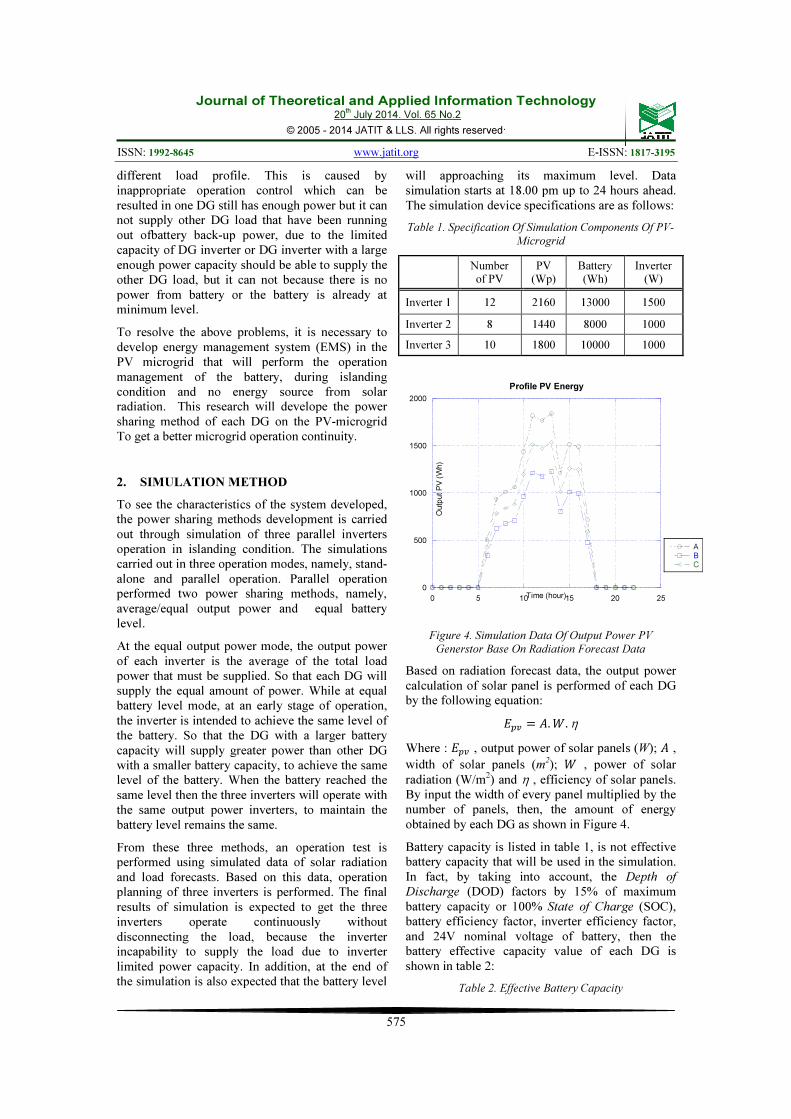
Table 1. Specification Of Simulation Components Of PV-
Microgrid
Number of PV
PV (Wp)
Battery (Wh)
Inverter (W)
Inverter 1 12 2160 13000 1500
Inverter 2 8 1440 8000 1000
Inverter 3 10 1800 10000 1000
0
500
1000
1500
2000
0 5 10 15 20 25
Profile PV Energy
ABC
Ou
tpu
t P
V (
Wh
)
Time (hour)
Figure 4. Simulation Data Of Output Power PV
Generstor Base On Radiation Forecast Data
Based on radiation forecast data, the output power
calculation of solar panel is performed of each DG
by the following equation:
��� � �.�.η
Where : ��� , output power of solar panels (W); � ,
width of solar panels (m2); � , power of solar
radiation (W/m2) and η , efficiency of solar panels.
By input the width of every panel multiplied by the
number of panels, then, the amount of energy
obtained by each DG as shown in Figure 4.
Battery capacity is listed in table 1, is not effective
battery capacity that will be used in the simulation.
In fact, by taking into account, the Depth of
Discharge (DOD) factors by 15% of maximum
battery capacity or 100% State of Charge (SOC),
battery efficiency factor, inverter efficiency factor,
and 24V nominal voltage of battery, then the
battery effective capacity value of each DG is
shown in table 2:
Table 2. Effective Battery Capacity
Journal of Theoretical and Applied Information Technology 20
th July 2014. Vol. 65 No.2
© 2005 - 2014 JATIT & LLS. All rights reserved.
ISSN: 1992-8645 www.jatit.org E-ISSN: 1817-3195
576
Generation Battery capacity (Ah/24V)
Inverter 1 8.000
Inverter 2 5.000
Inverter 3 6.000
100
200
300
400
500
600
700
800
900
0 5 10 15 20 25
Load Profile
A
B
C
Load (
Wh)
Time (hour)
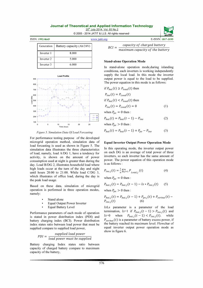
Figure 5. Simulation Data Of Load Forcasting
For performance testing purpose of the developed
microgrid operation method, simulation data of
load forcasting is used as shown in Figure 5. The
simulation data illustrates the three characteristics
of load, namely, load A/DG 1, have a tendency for
activity, is shown on the amount of power
consumption used at night is greater than during the
day. Load B/DG 2, illustrates household load where
high loads occur at the turn of the day and night
until hours 20:00 to 21:00. While load C/DG 3,
which illustrates of office load, during the day is
the peak load usage.
Based on these data, simulation of microgrid
operation is performed in three operation modes,
namely:
• Stand alone
• Equal Output Power Inverter
• Equal Battery Level
Performance parameters of each mode of operation
is stated in power distribution index (PDI) and
battery charging index (BCI). Power distribution
index states ratio between load power that must be
supplied compare to supplied load power,
��� � ��� ��� �������� ���������������� ���
Battery charging Index states ratio between
capacity of charged battery compare to maximum
capacity of the battery,
��� � ���������������������������������������������������
Stand-alone Operation Mode
In stand-alone operation mode,during islanding
conditiona, each inverters is working independently
supply the local load. In this mode the inverter
output power is equal to the load to be supplied.
The power equation in this mode is as follows:
if ���� �! " ����� �! then
�� �! � ����� �!
if ���� �! # ����� �! then
�� �! � ����� �! � 0 (1)
when ��� � 0 then :
���� �! � ���� � % 1! % �� (2)
when ��� ' 0 then :
���� �! � ���� � % 1! ( ��� % �� (3)
Equal Inverter Output Power Operation Mode
In this operating mode, the inverter output power
on each DG is an average of total power of three
inverters, so each inverter has the same amount of
power. The power equation of this operation mode
is as follows :
��, �! � �
∑ �
�� ����, �! (4)
when ��� � 0 then :
����, �! � ����, � % 1! % ∗ ��, �! (5)
when ��� ' 0 then :
����, �! � ����, � % 1! ( ���, �! ( ������� �! %��, �! (6)
Ls parameter is a parameter of the load
termination, =1 if ����, � % 1! ' ��, �! and =0 when ����, � % 1! # ��, �!. while ������� �! is a parameter of battery excess power, if
the battery reached its maximum level. Flowchar of
equal inverter output power operation mode as
show in figure 6.
Journal of Theoretical and Applied Information Technology 20
th July 2014. Vol. 65 No.2
© 2005 - 2014 JATIT & LLS. All rights reserved.
ISSN: 1992-8645 www.jatit.org E-ISSN: 1817-3195
577
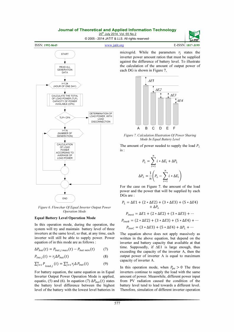
Figure 6. Flowchar Of Equal Inverter Output Power
Operation Mode
Equal Battery Level Operation Mode
In this operation mode, during the operation, the
system will try and maintain battery level of three
inverters at the same level, so that, at any time, each
inverter will still be able to supply power. Power
equation of in this mode are as follows :
∆���� �! � ����, ��� �! % ����� �! (7)
��, �! � � ∆���� �! (8)
∑ � �� ����,
�! � ∑ � ∆ �� ���� �! (9)
For battery equation, the same equation as in Equal
Inverter Output Power Operation Mode is applied,
equatio, (5) and (6). In equation (7) ∆���� �! states
the battery level difference between the highest
level of the battery with the lowest level batteries in
microgrid. While the parameters � states the
inverter power amount ration that must be supplied
against the difference of battery level. To illustrate
the calculation of the amount of output power of
each DG is shown in Figure 7,
A B C D E F
∆Ε1
∆Ε2
∆Ε3
∆Ε4
Figure 7. Calculation Illustration Of Power Sharing
Mode In Equal Battery Level
The amount of power needed to supply the load PL
is :
�� � ,� ∗ ∆� ( ∆��
��
∆�� � 1- .�� % ,� ∗ ∆�
��
/
For the case on Figure 7. the amount of the load
power and the power that will be supplied by each
DGs are :
�� � ∆�1 ( 2 ∗ ∆�2! ( 3 ∗ ∆�3! ( 5 ∗ ∆�4!( ∆��
��� � ∆�1 ( 2 ∗ ∆�2! ( 3 ∗ ∆�3! ( ⋯
��� � 2 ∗ ∆�2! ( 3 ∗ ∆�3! ( 5 ∗ ∆�4! ( ⋯
��� � 3 ∗ ∆�3! ( 5 ∗ ∆�4! ( ∆�� ( ⋯
The equation above does not apply massively as
written in the above equation, but depend on the
inverter and battery capacity that available at that
time. Supposedly, if ΔE1 is large enough, thus
exceeding the capacity of the inverter A, then the
output power of inverter A is equal to maximum
capacity of inverter A.
In this operation mode, when ��� ' 0 The three
inverters continue to supply the load with the same
amount of power. Meanwhile, different power input
from PV radiation caused the condition of the
battery level tend to lead towards a different level.
Therefore, simulation of different inverter operation
START
READ ALL GENERATION
DATA
CALCULATE THE TOTAL OF LOAD POWER (TLP),
CAPACITY OF POWER AVAILABLE (CPA)
TLP> CPA
DETERMINATION OF LOAD POWER, WITH
LOAD DISCONNECTION
I=1:24 (HOUR OF ONE DAY)
CALCULATION
OF LOAD POWER
ACCORDING TO AVERAGE OF
LOAD POWER
I=1:N (NUMBER OF
GENERATION)
END

Journal of Theoretical and Applied Information Technology 20
th July 2014. Vol. 65 No.2
© 2005 - 2014 JATIT & LLS. All rights reserved.
ISSN: 1992-8645 www.jatit.org E-ISSN: 1817-3195
578
method is performed, when ��� ' 0 where in this
condition each inverter will supply power
according to the local load power, which must be
supplied. So the power equation when ��� ' 0
becomes :
����, �! � ����, � % 1! ( ���, �! ( ������� �! %�����, �! (10)
Flowchar of equal battery level operation mode as
show in figure 7.
Figure 7. Flowchar Of Equal Battery Level Operation
Mode
3. SIMULATION RESULT AND
DISCUSSION
Stand alone Operation Mode
In this operating mode, it is shown that inverter 1 at
4 and 5 am was unable to supply power to the load,
this happened because of the battery level has
reached the minimum limit before the sun rises at 6
am. Meanwhile, for inverter 2 and inverter 3, the
battery capacity was enough to supply the load until
the sun is rising, so it is not necessary to disconnect
the load.
Figure 8. Graph Of Inverter Output Power
Figure 9. Battery Power Level
Since each inverter works independently, it can not
do power sharing between inverter, thus inverter 1
that has power shortage to supply the load, can not
be supplied from other inverters that have excess
power to supply the load. When viewed from the
battery level of each inverter, the maximum battery
level is reached at the end of the simulation.
Simulation results shown thatn the inverter output
power and battery level as shown in figure 8 and
figure 9.
START
READ ALL
GENERATION
DATA
SORT THE DATA
BASED ON CAPACITY
OF BATTERY
CALCULATE THE TOTAL
OF LOAD POWER (TLP),
CAPACITY OF POWER
AVAILABLE (CPA)
TLP> CPA
DETERMINATION OF
LOAD POWER, WITH
LOAD
DISCONNECTION
RADIATION < 0
CALCULATION OF
LOAD POWER
ACCORDING TO
EQUAL BATTERY
LEVEL
I=1:24
(HOUR OF ONE DAY)
I=1:N
(NUMBER OF
GENERATION)
CALCULATION
OF LOAD
POWER
ACCORDING TO
AVERAGE OF
LOAD POWER
I=1:N
(NUMBER OF
GENERATION)
END

Journal of Theoretical and Applied Information Technology 20
th July 2014. Vol. 65 No.2
© 2005 - 2014 JATIT & LLS. All rights reserved.
ISSN: 1992-8645 www.jatit.org E-ISSN: 1817-3195
579
Figure 10. Supplied Power To The Load
In accordance with equation (1) the power supplied
to the load is equal to the output power of the
inverter as shown in Figure 10. The performance
magnitude of this operation mode is the power
distribution index, PDI = 96.33% and battery
charging index , BCI = 97.84% which means not all
loads that should be supplied power from the
microgrid can be reached. Meanwhile at the end of
the simulation, the battery level condition is not in
maximum capacity, it only reached 97.84% of the
maximum capacity.
Equal Output Power Inverter Operation Mode
Based on the simulation results, it shown that when
all battery power of all inverter is enough to supply
the load, then the three inverters will supply the
load at the same amount. Meanwhile, if there is an
inverter that cannot supply the power because
running out of battery power back-up, then the two
remaining inverters, if possible, will supply the
total power that must be supplied by three inverters.
If cannot be complied, then the load will be
disconnected. As shown in the output power
inverter graph, figure 11, at 4:00 and 5:00, where
the battery capacity of inverter 2 has reached the
minimum level so that the load on the inverter 2 is
supplied from inverter 1 and inverter 3.
What should be noted with this approach is when
the difference of battery capacity between one
generation to another generation is large enough
there will be a condition where the battery capacity
of one generation has run out while the other
generation still have enough back-up power but it
can not supply the power to another generation that
have run out of battery power because it is
constrained by the capacity of the inverter. So load
termination must be done on the generation, as
shown in the simulation results, that load
termination on inverter 2 and 3 was performed at
6:00.
Figure 11. Inverter Output Power
Figure 12. Supplied Power To Load In Equal Output
Power Inverter
With power-sharing mechanism it evenly between
the three of PV generation, the amount of power
supplied by each inverter is not the same as that
power supplied to the load of each generation, as
shown in Figure 11 and 12. While the condition of
battery level during the simulation shown in Figure
13, which shown that the battery capacity of
inverter 2 already reached its minimum capacity at
3 o'clock in the morning, while the battery capacity
of inverter 3 reached its minimum capacity at 5.
Figure 13. Battery Level

Journal of Theoretical and Applied Information Technology 20
th July 2014. Vol. 65 No.2
© 2005 - 2014 JATIT & LLS. All rights reserved.
ISSN: 1992-8645 www.jatit.org E-ISSN: 1817-3195
580
Battery capacity on inverter 1 was never reached its
minimum capacity due to the battery capacity
inverter 1 is quite large. As shown in this mode,
that although inverter 2 is no longer supplying
power but the power can still be supplied by the
two remaining inverters, therefore the power on
that inverter is still working because of power
supply from the two remaining inverters. This is
shown on inverter 2, that although the inverter
output power already = 0 W at 3 o'clock to 5
o'clock, but the load on the inverter can still be
supplied with power from the two remaining
inverters. While the load on the inverter 3 was
terminated at 5 am and no longer be able to
received power from the inverter 1, because the
remaining power, is not sufficient to supply the
load on inverter 3. Consideration on load
termination on inverter 3 because remaining power
on the inverter 1 is only enough to supply power to
the inverter 1 and inverter 2.
The simulation results shown that the performance
of applied operation methods gives PDI = 97.92%,
which means that not all load is successfully
supplied with power, there are some part of load,
which should perform load termination. While BCI
= 100%means that on this operation mode at the
end of each simulation successfully recharged the
battery to reach its maximum capacity of the
battery charged.
Equal Battery Level Operation Mode
In this operating mode, as shown in the graph of
battery level, in which, at some time after the
simulation begins all three inverters have the same
battery level. When the same battery level is
reached, each inverter also supply the same power.
In this operation mode, allthree inverters are able to
supply the entire load that should be supplied as
shown in load forecast.
Figure 14. Inverter Ouput Power In Equal Battery Level
However, on the inverter itself, the amount of
output power is not the same with the load that
should be supplied, because the magnitude of the
output power of the inverter, following the
condition of the battery level in order to be
maintained at the same level. This is due to the
mechanism of power sharing between inverters. All
three inverters also successfully achieve the
maximum level of the battery capacity at the end of
the simulation.,. The simulation results can be seen
in Figure 14, 15 and 16.
Figure 15. Supplied Power To Load In Equal Battery
Level
Figure 16. Battery Level In Equal Battery Level
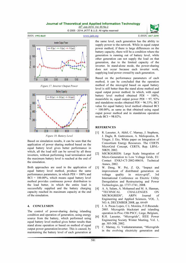
Meanwhile on the same operation mode, but during
output power radiation of three inverters based on
the load amount of each generations, the simulaton
result shows a different behavior, besides the
difference of inverter output power from every each
generation due to the differences of power load
that should be supplied. The battery level
achievement at the end of the simulation also
showed a different pattern, in which the two levels
of batteries tend to have the same value and battery
level reaches its maximum value just like at the
beginning of the simulation. The simulation results
shown in Figure 17 and 18.
Journal of Theoretical and Applied Information Technology 20
th July 2014. Vol. 65 No.2
© 2005 - 2014 JATIT & LLS. All rights reserved.
ISSN: 1992-8645 www.jatit.org E-ISSN: 1817-3195
581
Figure 17. Inverter Output Power
Figure 18. Battery Level
Based on simulation results, it can be seen that the
application of power sharing method based on the
equal battery level gives better performance in
which, all the load still can be served by all three
inverters, without performing load termination and
the maximum battery level is reached at the end of
the simulation.
Both approaches are used in the application of
equal battery level method, produce the same
performance parameters, in which PDI = 100% and
BCI = 100.00%, which means equal battery level
method provides continuous power distribution to
the load better, in which the entire load is
successfully supplied and the battery charging
capacity reached its maximum capacity at the end
of the simulation.
4. CONCLUSION
The control of power-sharing during islanding
condition and operation of generation, using energy
source from the battery, which performed using
equal battery level method gives better results than
stand alone operation or based on method of equal
output power generation/inverter. This is caused, by
maintaining the battery level of each generation at
the same level, each generation has the ability to
supply power to the network. While in equal output
power method, if there is large differences on the
battery capacity, there will be a condition where the
generation is running out of battery level, while
other generation can not supply the load on that
generation, due to the limited capacity of the
inverter. In stand-alone mode, the power-sharing
does not occur because each inverter work,
supplying load power owned by each generation.
Based on the performance parameters of each
method, it can be concluded that the operation
method of the microgrid based on equal battery
level is still better than the stand alone method and
equal output power method. In which, with equal
battery level method obtained PDI = 100%,
meanwhile in, equal output power PDI = 97, 92%
and standalone modes obtained PDI = 96.33%. BCI
value for equal battery level method obtained BCI
= 100.00%, as same as that obtained using equal
ouput power method and in standalone operation
mode BCI = 98.02%.
REFERENCES
[1] R. Lasseter, A. Akhil, C. Marnay, J. Stephens,
J. Dagle, R. Guttromson, A. Meliopoulos, R.
Yinger, J. Eto, White paper on Integration of
Consortium Energy Resources. The CERTS
MicroGrid Concept, CERTS, Rep. LBNL-
50829, 2002.
[2] MICROGRIDS: Large Scale Integration of
Micro-Generation to Low Voltage Grids, EU
Contact ENK5-CT-2002-00610, Technical
Annex, 2002.
[3] W. Deng, W. Pei, Z. Qi, “Impact and
improvement of distributed generation on
voltage quality in micro-grid", 3rd
International Conference on Electric Utility
Deregulation and Restructuring and Power
Technologies, pp. 1737-1741, 2008.
[4] A. A. Salam, A. Mohamed and M. A. Hannan,
"TECHNICAL CHALLENGES ON
MICROGRIDS", ARPN Journal of
Engineering and Applied Sciences, VOL. 3,
NO. 6, DECEMBER 2008, pp. 64-69
[5] J. A. Pecas Lopes, C.L Moreira, F.O.Resende.
2005. Microgrids blackstart and islanding
operation in Proc.15th PSCC, Liege, Belgium,
[6] R.H. Lasseter, “Microgrids", IEEE Power
Engineering Society Winter Meeting, Vol. 1,
pp. 305-308, 2002.
[7] C. Marnay, G. Venkataramanan, “Microgrids
in the evolving electricity generation and

Journal of Theoretical and Applied Information Technology 20
th July 2014. Vol. 65 No.2
© 2005 - 2014 JATIT & LLS. All rights reserved.
ISSN: 1992-8645 www.jatit.org E-ISSN: 1817-3195
582
delivery infrastructure", IEEE Power
Engineering Society General Meeting, pp. 18-
22, 2006.
[8] Para Kalpana, And Dr. A.Lakshmi Devi,
"Placement And Sizing Of Distributed
Generators In Distributed Network Based On
Lric And Load Growth Control", Journal of
Theoretical and Applied Information
Technology, 10th January 2013. Vol. 47 No.1
[9] Robert Lasseter, Micah Erickson, "Integration
of Battery-Based Energy Storage Element in
the CERTS Microgrid", CERTS, University of
Wisconsin-Madison, October 27, 2009
[10] Pukar Mahat, Jorge Escribano Jiménez, Eloy
Rodriguez Moldes, Sandra Iren Haug,Ireneusz
Grzegorz Szczesny, Karl Eide Pollestad,
Luminita Cristiana Totu, “A Micro-Grid
Battery Storage Management” Proceedings of
the IEEE PES General Meeting 2013, IEEE
Press, 2013
[11] Josep M. Guerrero, Lijun Hang, dan Javier
Uceda, “Control of Distributed
Uninterruptible Power Supply Systems”, IEEE
TRANSACTIONS ON INDUSTRIAL
ELECTRONICS, VOL. 55, NO. 8, AUGUST
2008