Embed Size (px)
Citation preview
1-62 530312-95
1993 Specifications CSJ 0500-03-429, etc.
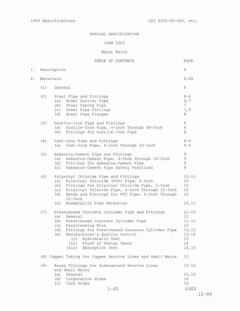
SPECIAL SPECIFICATION
ITEM 5303
Water Mains
TABLE OF CONTENTS PAGE
1. Description 6
2. Materials 6-28
(1) General 6
(2) Steel Pipe and Fittings 6-8(a) Steel Carrier Pipe 6,7(b) Steel Casing Pipe 7(c) Steel Pipe Fittings 7,8(d) Steel Pipe Flanges 8
(3) Ductile-Iron Pipe and Fittings 8(a) Ductile-Iron Pipe, 4-Inch Through 48-Inch 8(b) Fittings for Ductile-Iron Pipe 8
(4) Cast-Iron Pipe and Fittings 8-9(a) Cast-Iron Pipe, 4-Inch Through 24-Inch 8-9
(5) Asbestos-Cement Pipe and Fittings 9(a) Asbestos-Cement Pipe, 4-Inch Through 16-Inch 9(b) Fittings for Asbestos-Cement Pipe 9(c) Asbestos-Cement Pipe Safety Practices 9
(6) Polyvinyl Chloride Pipe and Fittings 10-11(a) Polyvinyl Chloride (PVC) Pipe, 2-Inch 10(b) Fittings for Polyvinyl Chloride Pipe, 2-Inch 10(c) Polyvinyl Chloride Pipe, 4-Inch Through 12-Inch 10(d) Bends and Fittings for PVC Pipe, 4-Inch Through 10
12-Inch(e) Nonmetallic Pipe Detection 10,11
(7) Prestressed Concrete Cylinder Pipe and Fittings 11-15(a) General 11(b) Prestressed Concrete Cylinder Pipe 11,12(c) Prestressing Wire 12(d) Fittings for Prestressed Concrete Cylinder Pipe 12,13(e) Manufacturer's Quality Control 13-15
(i) Hydrostatic Test 13(ii) Proof of Design Tests 14
(iii) Absorption Test 14,15
(8) Copper Tubing for Copper Service Lines and Small Mains 15
(9) Brass Fittings for Underground Service Lines 15-16and Small Mains(a) General 15,16(b) Corporation Stops 16(c) Curb Stops 16
2-62 530312-95
(d) Service Saddles 16
(10) Gate Valves, Tapping Valves and Tapping Sleeves 16-18(a) Gate Valves, 2-Inch Through 24-Inch 16,17(b) Tapping Valves 17(c) Tapping Sleeves 17,18(d) Air Release and Vacuum Relief Valve 18
(11) Butterfly Valves 18-19
(12) Valve Boxes 19
(13) Fire Hydrants 19-21(a) General 19(b) Hydrant Barrel 19,20(c) Shut-Off Valve and Inlet Shoe 20,21(d) Valve Stem 21(e) Gaskets and Seals 21(f) Painting 21
(14) Caulking Lead and Packing Material 21-22
(15) Polyethylene Film Wrap 22(a) General 22(b) Film 22(c) Polyethylene Tape 22
(16) Sand Backfill 22
(17) Concrete 23
(18) Grout for Prestressed Concrete Cylinder Pipe Joints 23-24(a) General 23(b) Nonshrink Grout 23,24
(19) Water Meter and Meter Vault 24-27(a) Pipe and Fittings 24(b) Tapping Valves 24(c) Line Valves 24(d) Commercial Meter Valves for Meter Installation 24,25(e) Fire Flow Meter Valves for Meter Installation 25(f) Turbine - Type Meter (Sizes 4-Inch through
10-Inch) 25,26(g) Meter Vaults 26,27
(i) General 26(ii) Precast Concrete Vault 26
(iii) Cast-in-Place Concrete Vault 26(iv) Solid Masonry Wall Vault 26,27(v) Frame and Cover 27
(20) Affidavit of Compliance 27
(21) Cement Stabilized Backfill 27
(22) Pressure Reducing Station 27-28
3. Construction Methods 28-56
(1) Excavation 28-29(a) Trenches 28,29(b) Existing Streets 29
3-62 530312-95
(2) Jacking, Boring or Tunneling Pipe 29-30(a) General 29(b) Jacking 30(c) Boring 30(d) Tunneling 30
(3) Handling of Pipe and Accessories 30-31(a) General 30,31(b) Cast-Iron or Ductile Iron Pipe, Valves 31
and Fittings(c) Asbestos-Cement Pipe 31(d) Polyvinyl Chloride Pipe 31
(4) Pipe Cutting 31
(5) Lowering of Pipe and Accessories into Trench 31
(6) Defective or Damaged Material 31
(7) Cleaning of Pipe and Accessories 31
(8) Laying of Pipe 32-34
(9) Joining of Pipe and Accessories 34-41(a) Cast-Iron Pipe, Ductile-Iron Pipe, Valves, 34
Hydrants and Fittings(b) Asbestos-Cement Pipe and Accessories 34,35(c) Polyvinyl Chloride Pipe and Accessories 35(d) Welded Joints for Steel Pipe 35-37(e) Flanged Joints for Steel Pipe 37(f) Rubber Gasketed Ball-and-Spigot Joints for 37,38
Use On Prestressed Concrete Cylinder Pipe(g) Welded Joints for Use On Prestressed Concrete 38,39
Cylinder Pipe(h) Flanged Joints for Use On Prestressed Concrete 39
Cylinder Pipe(i) Joint Grouting for Use On Prestressed Concrete 39-41
Cylinder Pipe
(10) Backfilling 41(a) Sand Backfill 41(b) Earth Backfill 41
(11) Valves and Fire Hydrants 42
(12) Fittings 42
(13) Boxes for Valves 42
(14) Wet Connections 42
(15) Polyethylene Film Wrap 43,44(a) Tube Type Wrap 43(b) Sheet Type Wrap 43,44(c) Bore Section Installation 44
(16) Painting Steel Pipe and Structures 44-46(a) General 44(b) External Coating Systems for Buried Steel Pipe 44-45
(i) General 44(ii) Tape Coating 45
4-62 530312-95
(iii) Cement-Mortar Coating 45(c) External Coating System for Steel Pipe 45
Installed above Ground (or Exposed),in Vaults, in Tunnels, and in Casings
(d) Internal Lining Systems for Steel Pipe 45(i) General 45
(ii) Coal-Tar-Epoxy Lining 45(iii) Shop Applied Cement Mortar Lining 45
(17) Sterilization of Mains and Testing for Leakages 46-48(a) Sterilization of Mains 46,47(b) Testing for Leakage 47,48
(18) Mains - Use of Completed Sections 48
(19) Mains - Lowering 48
(20) Copper Service Line Construction 48-51(a) Installing Service Lines 48,49(b) Corporation Stop Installation 49,50(c) Curb Stop Installation 50(d) Sequence of Work 50,51
(21) Abandonment of Water Mains 51
(22) Service Lines of Public Utilities 51-52
(23) Water Meter and Meter Vault 52-53(a) Salvaging of Existing Valves, etc. 52(b) Installation of Pipe, Tapping Sleeves, Valves, 52
Service Lines and Other Appurtenances(c) Vault Construction 52-53
(i) Precast Concrete Vault 52(ii) Cast-in-Place Concrete Vault 52
(iii) Solid Masonry Well Vault 52(iv) Frame and Cover 52,53
(d) Inspections 53(e) Adjusting Meter Vaults 53
(24) Removing and Relocating Fire Hydrants, Valves 53and Boxes
(25) Installation of Split Casing 53-54
(26) Securing, Supporting, and Anchoring 54(a) Pipe Supports 54(b) Anchorage of Main Line Fittings 54(c) Temporary Anchorage of Fittings 54
(27) Modifications for Cathodic Protection 54-55(a) General 54(b) Bonded Joints 55(c) Bonding Strap or Clip 55
(28) Auger Construction-Auger Holes and Auger Pits 55-56
(29) Removing and Salvaging Fire Hydrants 56
(30) Installation of the Nonmetallic Pipe Detection System 56
5-62 530312-95
4. Measurement 56-58
5. Payment 58-62
6-62 530312-95
1993 Specifications CSJ 0192-02-045
SPECIAL SPECIFICATION
ITEM 5303
Water Mains
1. Description. This Item shall consist of furnishing all labor,materials and equipment necessary to provide a complete water mainsystem in accordance with the plans and specifications and incompliance with the Department's Utility Accommodation Policy (Title43, T.A.C., Sections 21.31-21.55). The water mains shall be of thesizes, materials and dimensions shown on the plans and shall includeall pipe, all joints and connections to new and existing pipes, allcasing, valves, fittings, fire hydrants, blocking, etc., as may berequired to complete the work.
This item shall also govern for the materials and equipment to befurnished and for the methods to be followed for encasing existingwater lines with split steel encasement pipe, by the open cutmethod.
The abbreviations AWWA, ASA, ANSI and ASTM as used in thisspecification, shall refer to the following organizations ortechnical societies.
AWWA - American Water Works AssociationASA - American Standards AssociationASTM - American Society for Testing and MaterialsANF - American National Standards InstituteNSF - National Sanitation Foundation
Where reference is made to specifications of the above organizations, itshall be construed to mean the latest standard or tentative standard ineffect on the date of the proposal.
2. Materials.
(1) General. All pipe 6-inch and larger shall be acceptable,without penalty, to the Texas Fire Insurance Commission for usein water works distribution systems.
All materials used in this project shall be new and unusedunless otherwise specified on the plans or in the proposal.
(2) Steel Pipe and Fittings.
(a) Steel Carrier Pipe.
All steel pipe, 4-inch through 24-inch, which is intendedfor use as carrier pipe in the distribution system shallconform to the requirements of AWWA Standard C200. Pipesteel shall meet the requirements of ASTM A36, ASTM A570Grade 36, ASTM A53 Grade B, ASTM A135 Grade B, or ASTMA139 Grade B as a minimum. Pipe shall also be subject tothe requirements of Underwriters Laboratories,Inc. Specification for "Steel Pipelines for Underground
7-62 530312-95
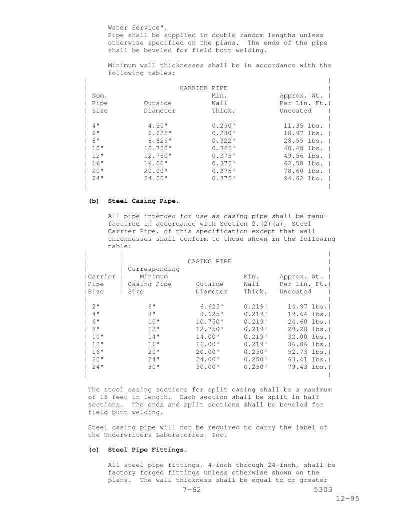
Water Service".Pipe shall be supplied in double random lengths unlessotherwise specified on the plans. The ends of the pipeshall be beveled for field butt welding.
Minimum wall thicknesses shall be in accordance with thefollowing tables:
| || CARRIER PIPE || Nom. Min. Approx. Wt. || Pipe Outside Wall Per Lin. Ft.|| Size Diameter Thick. Uncoated || || 4" 4.50" 0.250" 11.35 lbs. || 6" 6.625" 0.280" l8.97 lbs. || 8" 8.625" 0.322" 28.55 lbs. || 10" 10.750" 0.365" 40.48 lbs. || 12" 12.750" 0.375" 49.56 lbs. || 16" 16.00" 0.375" 62.58 lbs. || 20" 20.00" 0.375" 78.60 lbs. || 24" 24.00" 0.375" 94.62 lbs. || |
(b) Steel Casing Pipe.
All pipe intended for use as casing pipe shall be manu-factured in accordance with Section 2.(2)(a), SteelCarrier Pipe, of this specification except that wallthicknesses shall conform to those shown in the followingtable:
| | || | CASING PIPE || | Corresponding ||Carrier | Minimum Min. Approx. Wt. ||Pipe | Casing Pipe Outside Wall Per Lin. Ft.||Size | Size Diameter Thick. Uncoated || || 2" 6" 6.625" 0.219" 14.97 lbs.|| 4" 8" 8.625" 0.219" 19.64 lbs.|| 6" 10" 10.750" 0.219" 24.60 lbs.|| 8" 12" 12.750" 0.219" 29.28 lbs.|| 10" 14" 14.00" 0.219" 32.00 lbs.|| 12" 16" 16.00" 0.219" 36.86 lbs.|| 16" 20" 20.00" 0.250" 52.73 lbs.|| 20" 24" 24.00" 0.250" 63.41 lbs.|| 24" 30" 30.00" 0.250" 79.43 lbs.|| |
The steel casing sections for split casing shall be a maximumof 16 feet in length. Each section shall be split in halfsections. The ends and split sections shall be beveled forfield butt welding.
Steel casing pipe will not be required to carry the label ofthe Underwriters Laboratories, Inc.
(c) Steel Pipe Fittings.
All steel pipe fittings, 4-inch through 24-inch, shall befactory forged fittings unless otherwise shown on theplans. The wall thickness shall be equal to or greater
8-62 530312-95
than the pipe to which the fitting is to be welded. Theends of the fitting shall be beveled for field buttwelding.
All bends shall be long radius fittings unless otherwiseshown on the plans.
(d) Steel Pipe Flanges.
Steel pipe flanges, where called for on the plans, shallconform to AWWA Standard C207 for Class D Flanges (samediameter and drilling as Class 125 cast-iron flanges ASAB16.1).
All asbestos-cement, ductile-iron cast-iron or PVC pipeconnections shall be made with one (1) cast-iron,ductile-iron or PVC bell flange and one (1) steel slip-onflange and shall be electrically isolated. The use ofinsulating gaskets, plastic bolt sleeves and washers ofinsulating gasket material backed with zinc-plated or hot-dip galvanized washers, or, epoxy coated bolts, nuts andwashers used with an insulating gasket are approved forthis purpose.
(3) Ductile-Iron Pipe and Fittings.
(a) Ductile-Iron Pipe, 4-Inch Through 48-Inch.
All ductile-iron pipe shall conform to the requirements ofAWWA Standard C151. Unless otherwise specified on theplans, all pipe shall be of thickness Class 50 regardlessof pipe size. Joints shall be of the push-on type unlessotherwise specified on the plans. Push-on joints shallconform with the requirements of ASA Specification A21.11(AWWA C111).
The inside surfaces of the pipe shall be coated with acement mortar lining in accordance with the requirementsof ASA Specification A21.4 (AWWA C104).
(b) Fittings for Ductile-Iron Pipe.
All fittings for use with ductile-iron pipe of nominalsizes 4-inch through 48-inch shall conform to AWWAStandard C110.
Joints shall be of the push-on type unless otherwisespecified on the plans. Push-on joints shall conform tothe requirements of ASA Specification A21.11 (AWWA C111).
All fittings shall be furnished with standard outsidecoatings. The inside surfaces of the fittings shall becoated with a cement mortar lining in accordance with therequirements of ASA Specification A21.4 (AWWA C104), andNSF/ANSI Standards./lm 12
(4) Cast-Iron Pipe and Fittings.
(a) Cast-Iron Pipe, 4-Inch Through 24-Inch.
All cast-iron pipe shall conform to the requirements of
9-62 530312-95
AWWA Standard C106 or AWWA Standard C108.
Unless otherwise specified on the plans, all pipe shall beof the thickness required for "Laying Condition F" andfive (5) feet of cover. The working pressure shall be 150psi.
Joints shall be of the push-on type unless otherwisespecified on the plans. Push-on joints shall conform withthe requirements of ASA Specification A21.11 (AWWA C111).
All pipe shall be furnished with standard outsidecoatings. The inside surfaces of the pipe shall be coatedwith a cement mortar lining in accordance with therequirements of ASA Specification A21.4 (AWWA C104). ,and NSF/ANSI Standards. (B) Cast-Iron Fittings.
All fittings for use with cast-iron pressure pipe ofnominal sizes 4-inch through 24-inch shall conform to therequirements of AWWA Standard C110. The fittings shall bedesigned for a minimum working pressure of 150 psi.
Joints shall be of the push-on type unless otherwisespecified on the plans. Push-on joints shall conform tothe requirements of ASA Specification A21.11 (AWWA C111).
All fittings shall be furnished with standard outsidecoatings. The inside surfaces of the fittings shall becoated with a cement mortar lining in accordance with therequirements of ASA Specification A21.4 (AWWA C104).
(5) Asbestos-Cement Pipe and Fittings.
(a) Asbestos-Cement Pipe, 4-Inch Through 16-Inch.
Unless otherwise shown on the plans, all pipe shallconform to the requirements of AWWA Standard C-400-80, orlatest revision, and shall be Class 200. Pipe lengthsshall be limited to a maximum of 6 feet 6 inches.
Valves for use with asbestos-cement pipe shall conform tothe requirements of Subarticle 2.(10), Gate Valves,Tapping Valves and Tapping Sleeves, of this specificationexcept that valve ends shall be of the standard push-onjoint type for use with asbestos-cement pipe. Wherevernecessary for good workmanship, the ends of the asbestos-cement pipe shall be machined or asbestos-cementtransition fittings shall be used.
(b) Fittings for Asbestos-Cement Pipe.
Fittings for use with asbestos-cement pipe shall conformto the requirements of Section 2.(4)(b), Cast-IronFittings, of this specification.
(c) Asbestos-Cement Pipe Safety Practices.
Safety Practices as outlined in AWWA Publication M16 shallbe followed. All "recommended" practices contained inAWWA Publication M16 shall be strictly adhered to andshall be "mandatory practices" for this project.
10-62 530312-95
(6) Polyvinyl Chloride Pipe and Fittings.
(a) Polyvinyl Chloride (PVC) Pipe, 2-Inch.
All PVC pipe shall be manufactured in accordance with therequirements of ASTM Designation D2241 for PVC 1120 or PVC1220 and shall have a standard thermoplastic pipedimension ratio (SDR) equal to 21.
All PVC pipe shall have integral bell type gasketed push-on joints or shall be plain end pipe with twin-gasketedcouplings conforming to the requirements of ASTMDesignation D3139 for push-on-type joints. Rubber gasketsshall conform to the requirements of ASTM DesignationD1869.
All PVC pipe furnished shall be self-extinguishing.
Valves for use with PVC pipe shall conform to therequirements of Subarticle 2.(10), Gate Valves, TappingValves and Tapping Sleeves of this specification, exceptthat valve ends shall be of the push-on-joint type for usewith PVC pipe.
(b) Fittings for Polyvinyl Chloride Pipe, 2-Inch.
All fittings for 2-Inch PVC shall have a minimum pressurerating of 200 psi. They shall be solvent-weld, sockettype conforming to the requirements of ASTM D2466, orgasketed push-on conforming to the requirements of ASTMD2241. All PVC solvent cements shall be manufactured inaccordance with ASTM D2564.
(c) Polyvinyl Chloride Pipe, 4-Inch through 12-Inch.
All PVC pipe shall conform to AWWA C900.
It shall be Class 150 DR-18 and have cast iron equiva-lent outside diameters unless otherwise specified. Itshall be furnished in nominal 20 foot lengths, and shallbe self extinguishing.
The joints shall conform to the same requirements as thosespecified for 2-Inch PVC pipe.
(d) Bends and Fittings for PVC Pipe, 4-Inch through 12-Inch.
All bends and fittings furnished shall be rubber gasketedcast iron or ductile iron pressure fittings conforming toAWWA C110, unless otherwise specified on the plans. Theyshall be polyethylene wrapped.
(e) Nonmetallic Pipe Detection.
Where nonmetallic pipe is installed longitudinally, amethod of detecting the location of the nonmetallic pipeshall be required. A durable metal detection wire shouldbe used in conjunction with plastic tracer tape unless theplastic tracer tape contains the detection wire. Thespecific method used shall be approved by the Engineer.
11-62 530312-95
The materials involved shall be as specified by themanufacturer.
(7) Prestressed Concrete Cylinder Pipe and Fittings.
(a) General.
The City Engineer reserves the right to visit themanufacturing facilities for prestressed concrete cylinderpipe, without notice. The review will be to determinecompliance with this specification. Such review by theEngineer shall not be construed in any way of relievingthe Contractor of his responsibilities under thiscontract.
(b) Prestressed Concrete Cylinder Pipe.
Prestressed concrete cylinder pipe shall meet therequirements of AWWA C301 and AWWA M9, latest edition,except as modified herein. Full circumferential welds atjoints requiring welding shall be provided. Whenspecified on the plans, the pipe shall be modified forcathodic potection in accordance with the SpecialSpecification Item, "Cathodic Protection Systems for LargeDiameter Water Main".
The pipe design shall be based upon the lesser of themeasured properties of the material actually used in themanufacture of the pipe or the minimum stated values,required in this specification, for said properties andnot generic values.
Pipe and fittings shall be designed per AWWA C301,Appendix B, to withstand the most critical simultaneousapplication of external loads and internal pressures. Thedesign shall be based on a minimum of AASHTO HS-20 loading(AREA E-80 loads where indicated) and depths of bury asindicated. Marston Earth Loads for a transition widthtrench shall be used in the pipe design for pipe with zeroto 16 feet of cover. Marston's Earth Loads for a trenchwidth of Outside Diameter (of pipe) plus three (3) feetmay be used for pipe with greater than 16 feet of cover.The unit weight of fill shall be no less than 120 lbs. percubic foot. Ninety-degree Olander coefficients for theearth load and water weight contained in the pipe alongthe 15-degree Olander coefficients for the pipe weightshall be utilized when calculating the moments and thrustsin the pipe wall. The groundwater level shall be assumedto be equal to natural ground surface or criticalconditions.
The allowance for tensile stress in the concrete core ormortar coating at any combination of external loadings aninternal pressures shall not exceed 3.5 times the squareroot of the compressive strength of concrete. The maximumallowable compressive stress in the concrete core ormortar coating due to any combination of external loads orinternal pressures (working and transient) shall be 0.55times the compressive strength of concrete.The intenal design pressures are as follows:
12-62 530312-95
Working pressure = 100 psi.
Hydrostatic field test pressure = 150 psi.
Maximum pressure due to surge = 150 psi.
Minimum pressure due to surge = -5 psi.
(c) Prestressing Wire.
Prestress wire must be furnished from an independentmanufacturer (i.e., a manufacturer with no legal orfinancial ties to the pipe manufacturer). Foreignmanufactured wire shall be tested by a local independentlaboratory or the pipe manufacturer at the contractorsexpense.
All mechanical tests required in ASTM A 648 shall beperformed by the wire manufacturer on a sample taken fromone (1) end of each coil and selected to berepresentative of normal wire drawing conditions. Thepipe manufacturer shall test a sample, for all mechanicalrequirements, from one (1) of each five (5) consecutivelyproduced coils or fraction thereof in each lot.
The pipe manufacturer shall require that the wiremanufacturer submit certified results of chemical andmechanical tests, performed by the wire manufacturer.Mechanical tests shall be performed by the pipemanufacturer. The pipe manufacturer shall attest to suchin his affidavit of compliance.
Tests of all prestressing wire are to be submitted forrecord purposes, indicating compliance with thespecifications. Submission of the test specimens is notrequired. The expense of the tests shall be borne bymanufacturer.
The surface temperature of the prestressing wire at anypoint in the drawing process shall not exceed 360 F. Thewire manufacturer shall audit the surface temperature ofthe wire throughout the length of the wire drawingprocess daily for each working shift producing ASTM A 648wire, or shall take similar dependable precautions toprovide the maximum wire surface temperature is notexceeded.
(d) Fittings for Prestressed Concrete Cylinder Pipe.
The Contractor shall furnish all fittings and specials (bendsand elbows) required for bends, branches, accessmanholes, air valve and blowoff connections, andconnections to line valves and other fittings. Fittingsand specials shall be designed in accordance with thedesign details and AWWA C301, latest edition. Fittingsand specials are subject to the same internal andexternal loads as the straight pipe.
The pipe joints shall be rubber gasketed or weldedbell-and-spigot type except where flanged joints arerequired for valves and fittings as shown on the
13-62 530312-95
drawings. In tunnel, auger or boring installations, theoutside diameter of the pipe shall have a constantoutside diameter from bell to spigot end. Pipe jointsshall be able to withstand jacking forces and shall bemanufactured in accordance with, and meet therequirements of AWWA C301, and be able to withstandjacking forces. See paragraphs referring to joints andjointing for additional requirements.
All rubber gasketed joints shall be bonded as shown onthe drawings to provide electrical continuity along theentire pipeline except where insulating flanges arecalled for.
Pipe sections shall be provided in standard lengths witha minimum of 16 feet except for special fittings orclosure sections as indicated on the shop drawings. Eachpipe section shall be clearly marked to show locationsand pipe pressure.Curves and bends shall be made by deflecting the joints,by use of beveled joints, or by a combination of the two(2) methods, unless otherwise indicated on the plans.The Contractor may submit details of other methods ofproducing curves and bends for consideration by theEngineer, and if deemed satisfactory, shall be installedat no additional cost.
All pipe flanges shall conform to AWWA C207 requirementsfor standard steel flanges of the pressure classcorresponding to the pipe class.
All exposed steel parts of flanges, bolts, access manholecovers, etc., shall be coated with coal tar epoxy system.All steel parts shall be shop blasted to SSPC-SP10 andgiven one shop coat of ACRE 4421 "Inhibitive EpoxyPrimer" or approved equal, applied by spray gun to aminimum thickness of 2.0 mils DFT. After installation,the exposed steel parts shall be thoroughly cleaned, inaccordance with the coating manufacturer'srecommendations and as approved by the Engineer, toremove soil, grease, etc., to insure a proper surface forthe application of the "Coal Tar Epoxy". Once thesurfaces have been properly cleaned, all exposed steelparts, including the interior of blind flanges, shall begiven two (2) coats of ACRO 4462 "Coal Tar Epoxy" orequal, to a total minimum dry film thickness of 18 mils.
Pipe from inventory is permitted if all specificationsand certifications can be met. Testing records requiredby specifications must be provided.
(e) Manufacturer's Quality Control.
(i) Hydrostatic Test.
Pipe cylinders shall be hydrostatically tested atthe factory in accordance with AWWA C301, Section3.5.3.
14-62 530312-95
(ii) Proof of Design Tests.
The design of each size and class of concretecylinder pipe shall be verified by tests conductedon representative specimens. The tests describedin this paragraph are for proof of design only.It is not necessary that these tests be made onpipe manufactured specifically for this contract.Certified reports covering tests made on otherpipe of the same size and design as specifiedherein and manufactured from materials ofequivalent type and quality may be accepted asadequate proof of design.
No cracks shall be permitted in the pipe mortarcoating of completed pipe sections at thehydrostatic test pressure. The test pressureshall be held for a minimum of 15 minutes in orderto allow time to thoroughly inspect the mortarcoating for cracks. If any cracks are found, thepipe shall be rejected.
Additionally, one (1) pipe from each design classshall be tested in a 3-edge bearing test to anequivalent load of the earth load plus liveloadings. No cracks shall be permitted on theinside of the core.
If any cracks are found, two (2) more samples fromthat design class shall be tested; and if nocracks are found, the lot of pipe from that classshall be accepted. If either of the two (2)additional tests fail, the lot shall be rejected.The manufacturer may elect to test each pipe froma failed lot and any individual pipe that does notfail shall be accepted. Written certification anda copy of all test reports shall be submitted.
(iii) Absorption Test.
A water absorption test shall beperformed on samples of cured mortar coating takenfrom each working shift. The mortar coatingsamples shall have been cured in the same manneras the pipe. A test value shall consist of theaverage of a minimum of three (3) samples takenfrom the same working shift. The test methodshall be in accordance with ASTM C497, method A.The average absorption value for any test shallnot exceed nine (9) percent and no individualsample shall have an absorption exceeding 11percent.
Tests for each working shift shall be performed ona daily basis until conformance with theabsorption requirements has been established basedupon the passing of 10 consecutive tests, at whichtime testing may be performed on a weekly basisfor each working shift. With failing absorptiontest results daily testing shall be resumed foreach working shift and shall be maintained until
15-62 530312-95
conformance to the absorption requirements isreestablished by 10 consecutive passing tests.
(8) Copper Tubing for Copper Service Lines and Small Mains.
All 3/4 inch, 1 inch, 1-1/2 inch and 2 inch copper tubing forunderground service shall be Type "K" soft annealed with theproper bending temper and shall conform to ASTM Designation B88and Federal Specification WW-T-799 with the followingexceptions:
Section 14 of ASTM Designation B88 is hereby modified toprovide for the following number of samples for each sizeof tubing:
For each 7500 feet of tubing ................one (1)sample
Items of less than 7500 feet of tubing.......one (1)sample
3/4 inch and 1 inch tubes shall be furnished in coils,each containing 60 feet (flat coils are preferred).1-1/2 inch and 2 inch tubes shall be furnished in straightlengths of 40 feet.
(9) Brass Fittings for Underground Services Lines and Small Mains.
(a) General.
Unless otherwise provided herein, brass fittings will berequired in underground installations of service lines andsmall mains in the water distribution system.
Brass fittings shall be composed of Copper Alloy No. 836conforming to the requirements of ASTM Designation B62.The general pattern for each fitting shall conform to thatof standard brass fittings as manufactured by MuellerCompany, Hays Manufacturing Company or approved equal.
Unless otherwise specified herein or on the plans,fittings shall be of the flared type for use with Type "K"soft annealed copper tubing. However, compressionfittings may be used for unions except where they occurunder existing or future paving.
Each fitting shall have the manufacturer's name ortrademark and size plainly stamped into or cast on thebody. The fittings shall be such that they can beassembled or inserted using the same size open endwrenches and tapping machines as are used with theequivalent fittings.
Stops shall be furnished without check or waste.Waterways shall not be smaller in diameter than thenominal size of the stop and shall be accurately finishedto a watertight joint; all nuts and washers shall be facedto a true fit; and the design shall be such that the jointwill remain watertight and reasonably easy to operateafter repeated use over a number of years. All externalthreads shall conform with AWWA Standard C800 and, on
16-62 530312-95
corporation stops, shall be protected in shipment byplastic coatings or an alternate approved method.
Each corporation stop and curb stop shall be tested at thefactory. Each stop shall be submerged in water for 10seconds at not less than 85 psi with the stop in bothclosed and opened positions. Any fitting that shows airleakage shall be rejected.
(b) Corporation Stops.
Inlet ends shall be of one of the following types:standard corporation stop threads as specified in Table 1,AWWA C800; iron pipe thread (permissible for use withservice saddles only).
The valve body shall be of one of the following types:tapered plug type; O-ring seal straight plug type; or therubber seat ball type.
For PVC pipe, corporation stops shall be all brass andspecifically designed for use with PVC pipe.
(c) Curb Stops.
Inlet ends shall have flared copper connections orcompression type fittings unless otherwise specified onthe plans.
The valve body shall be of straight through or angledmeter stop design equipped with padlock wings and shall beof the O-ring seal straight plug type or the rubber seatball type.
The outlet shall have female iron pipe threads or swivelnut meter spud threads and 1 inch stops and shall have two(2) hole flanges for 1-1/2 inch and 2 inch sizes.
(d) Service Saddles.
Service saddles shall have dual straps and shall consistof one of the following types: brass body and straps;ductile-iron body and straps, vinyl coated; ductile-ironbody, vinyl coated with stainless steel straps.
(10) Gate Valves, Tapping Valves and Tapping Sleeves.
(a) Gate Valves, 2-Inch Through 24-Inch.
Gate valves shall conform to AWWA Standard C500 and thefollowing supplemental specifications:
All valves shall be of the double-disc type with non-rising stems.
Unless otherwise specified on the plans, valve endshall be of the push-on type; rubber gaskets shall befurnished with the valves.
Unless otherwise specified on the plans, each valveshall have a two (2) inch square operating nut,
17-62 530312-95
operating counter clockwise (turning to the left) toopen the valve.
Valves of sizes 2-inch through 16-inch shall be of thevertical type without bypasses.
Valves of sizes 20-inch and larger shall be of thehorizontal type with enclosed steel bevel gears andstandard size bypass valves.
Valves for use in fire flow meter installations shallconform to the above specifications except that they shallbe outside screw and yoke valves and shall carry the labelof the Underwriters Laboratories, Inc.
(b) Tapping Valves.
Tapping valves shall meet all the requirements of gatevalves, as listed above, except for type of joints; inletjoint shall be flanged and drilled for Class 125 (ASAB16.1) and shall have machined projections, for alignmentpurposes, to mate with the tapping sleeves. Outlets shallhave hub end push-on type or caulked lead type joints asspecified unless otherwise specified on the plans; outsideflanges shall be drilled (or slotted) to meet standardMueller Tapping Machine Model Nos. CL-12, CC-25, or CL-25or Hayes or equal.
The valve seat opening shall be such that a full sizeshell cutter for the nominal size tap may pass through thevalve without any contact with the valve body.
(c) Tapping Sleeves.
Tapping sleeves shall be of the split sleeve type withflange tapping outlet. Each flange shall be drilled tomatch Class 125 (ASA B16.1) cast-iron pipe flanges andshall have a machined recess to mate with the machinedprojections on the tapping valve for alignment purposes.
Tapping sleeve bodies shall be cast-iron with hub ends foruse on cast-iron pipe or mechanical joint ends for use onasbestos-cement pipe, except as noted below:
Welded steel tapping sleeve bodies may be used in lieuof cast-iron, subject to the following limitations andrequirements:
Approved sizes shall range from 6 inch to 4 inchupward, but no "size-on-size" sleeve will be permitted(i.e., 4 inch x 4 inch, 6 inch x 6 inch, etc.). Toaccomplish size-on-size connections, the next smallertap may be made and an LEB (large end bell) increaserused. Where fire service from 6 inch main isapproved, a cast-iron split sleeve only will bepermitted.
The body shall be of heavy welded steel construc-tion. The top half of the body shall be grooved topermanently retain a neoprene O-ring seal against theoutside diameter of the pipe.
18-62 530312-95
Bolts and nuts shall conform with the latest publishedAWWA Standard C500, Section 9, and shall be coatedwith a 100 percent vinyl resin (or shall be made ofcorrosion resistant material).
The finish on tapping sleeves shall be 100 percentvinyl resin on all surfaces with a minimum thicknessof 10 mils.
A final seal from backfill shall be made by com-pletely encasing the tapping sleeve with sheet vinylof eight (8) mil thickness. Tape to secure thiswrapping shall be that manufactured for this purposeof Poly- ken No. 900, Scotch Wrap No. 50 or approvedequal.
Steel tapping sleeves shall be Smith Blair No. 623,Rockwell No. 623 or approved equal.
(d) Air Release and Vacuum Relief Valve.
Combination air release and vacuum relief valves shall beprovided with flanged inlet and outlet connections asspecified on the plans. High pressure air release valvesshall have an inlet and outlet, and orifice. The airrelease and vacuum release valves shall be APCO 145C, GAFIG.945 or approved equal. The air and vacuum reliefvalve shall be constructed of materials as follows: bodyand cover, ASTM A 45, Class 30 cast iron; float, ASTM A240 stainless steel; seat, Type 304 stainless steel andBuna-N. All other valve internals shall be stainlesssteel or bronze.
(11) Butterfly Valves.
Butterfly valves shall conform to the requirements of AWWAStandard C504 and the following special conditions:
Valves shall be of the short body type designed forclosing against a flow velocity of 16 feet per second at anormal working pressure of 150 psi and with a downstreampressure of zero (0) psi (Class 150B).
Valves shall have rubber seats mounted either on the discor in the body and the seats shall be adjustable for valvesizes 30 inch and larger; the disc shall be cast-iron oralloy cast-iron conforming to ASTM Designation A48, Class40, or ASTM A436, Type 1. The seating edge shall be 18-8stainless steel.
The valve body shall be cast-iron conforming to ASTMDesignation A126, Class B or ASTM Designation A48, Class40.
Joint types for installation with cast-iron or ductile-iron pipe shall be push-on or flanged (flanged valvescoupled to Bell-Flange adapters may be used). Flangesshall conform in dimensions and drilling to ASASpecification B16.1 for cast-iron body valves, Class 125.Bolts conforming to AWWA Standard C500, Section 9, shall
19-62 530312-95
be used in all valve installations, including bolts foroperators, housing, etc. Flanged joints shall be used forall steel or concrete steel cylinder pipe.
Manual operators shall be properly sized gear type forvalves 30 inch and larger. Traveling nut and lever typeoperators may be used on 24 inch and smaller valves. Theoperator shall be equipped with a two (2) inch square nutoperating clockwise to open the valve. All gears ortraveling nut and lever accessories shall be totallyenclosed and suitable for submersible service. Operatorsshall conform to the requirements of AWWA Standard C504and shall be equipped with adjustable limit stop devices.
Butterfly valves may be used as line valves in lieu of gatevalves in sizes 16 inch, 20 inch, and 24 inch and shall be usedexclu- sively in sizes larger than 24 inch.
(12) Valve Boxes.
All valve box assemblies shall conform to the Texas Departmentof Transportation Standard Water Details F-4 "Valve BoxDetails". The chemical composition of Casting "A" shallconform to the requirements of AWWA Standard C110. The pipesection of each valve box shall be cast-iron or ductile ironconforming to the requirements of this special specificationexcept that a cement mortar lining will not be required. Theinside and outside surfaces of the valve box assembly shall becoated with a standard bituminous coal tar coatingapproximately one (1) mil in thickness.
(13) Fire Hydrants.
(a) General.
Fire hydrants shall conform to the requirements of AWWAStandard C502, except as modified or supplemented herein.They shall be of dry-top design and collision-safetyconstruction. Fire hydrants shall be mueller A-423 orapproved equal.
Installation of used, salvaged, or reconditioned firehydrants will not be permitted unless otherwise shown onthe plans.
(b) Hydrant Barrel.
The lower hydrant barrel shall be fabricated as a singlepiece, and shall be connected to the upper hydrant barrelby means of a joint coupling that will provide threehundred sixty degree (360) rotation of the upper barrel.The bury length shall be as specified and shall be thedistance from the bottom of the inlet to the ground line.The ground line shall be clearly marked on the barrel.
The hydrant barrel shall be provided with a non-tappeddrain opening, completely of bronze or bronze lined. Thedrain valve shall operate, without use of a spring, todrain the barrel when the hydrant valve is in the fully-closed position and to completely close the drain openingso as to prevent leaking when the hydrant valve is in the
20-62 530312-95
open position.
Each hydrant barrel shall be equipped with two (2) 2-1/2inch nominal inside diameter hose nozzles and one (1) four(4) inch nominal inside diameter pumper nozzle with 4.480thread configuration conforming with National (American)Standard Fire Hose Coupling Screw Threads (per NFPANo. 194 and ANSI B26-1925, latest revision). Nozzlesshall be securely fastened into the upper barrel bymechanical means, installed by turning counterclockwise,and shall be locked in place with a security device. Allnozzles shall be provided with nozzle caps securelyattached to the hydrant barrel with chains of not lessthan 1/8 inch diameter and with rubber or neoprenegaskets. The pumper nozzle shall be so situated as toallow an unobstructed radius of 10 inches from thethreaded surface of the nozzle throughout the path oftravel of a wrench or other device used to fasten a hoseto the nozzle.
The hydrant shall be oriented so that the pumper nozzlefaces the curb or street nearest the hydrant.
The barrel joint connecting the upper and lower hydrantsections shall be designed so that the hydrant shut-offvalve will remain closed and reasonably tight againstleakage in the event of an impact accident resulting indamage or breaking of the hydrant above or near groundlevel. The joint shall be provided with a breakable boltflange or breakable coupling that will include a minimumof eight (8) bolts.
The operating and hold down nuts shall be fabricated ofstainless steel or of cast or ductile iron with bronzeinserts or, in the alternative, a security device will beprovided with each hydrant employing a bronze operatingnut to protect this feature of the hydrant from maliciousmischief or unauthorized removal. Any such securitydevices shall not require a special tool for normal off/onoperation of the hydrant. Hold down assemblies shall befabricated of suitable metallic materials for the serviceintended.
The hydrant barrel shall be designed to permit the use ofone or more standard extensions, which shall be availablefrom the hydrant manufacturer, in lengths from 6-inches to60-inches in 6-inch increments.
(c) Shut-off Valve and Inlet Shoe.
Hydrants shall have compression type shut-off valves whichclose with the water pressure, with center stemconstruction. Each shut-off valve shall be circular andnot less than 5-1/4 inches in diameter. The valve seatring shall be bronze, threaded into a bronze drain ring toprovide an all-bronze drainway. The seat ring and mainvalve assembly shall be such that it can be removed fromabove ground through the upper barrel by means of a light-weight seat removal wrench. The valve seat facing shallbe constructed of molded rubber having a Durometer ratingof 90 plus or minus five (5), and shall be a minimum
21-62 530312-95
thickness of 1/2 inch.
Unless otherwise specified on the plans the inlet shoeshall be an elbow with AWWA Standard bell designed for anominal six (6) inch hub end, push-on or mechanical jointassembly as specified.
(d) Valve Stem.
The valve stem shall be provided with a breakable stemcoupling opposite the barrel breakaway feature.Connecting pins and locking devices shall be constructedof bronze or other corrosion-resistant material. Thevalve stem shall be provided with a bronze sleeve,suitable seals and travel stop. Operating threads andbearings shall be fully lubricated when opening or closingthe shut-off valve; the lubricant shall be contained in alubricating reservoir which shall be sealed at the top andbottom. The operating assembly shall be equipped with athrust bearing or lubricated thrust collar to minimizeoperating torque.
The operating nut shall be 1-3/16" pentagon and shall opencounterclockwise (turning to the left) per City of Alvinspecifications.
(e) Gaskets and Seals.
All dynamic seals shall be "O-ring" type, oil-resistantmaterial, which does not require adjustment for awatertight seal. All moving parts in contact with theseal shall be bronze or other corrosion-resistantmaterial.
Static seals shall be rubber, asbestos or other approvedcomposition.
(f) Painting.
Fire hydrants shall be shop coated with a suitable primerand finish painted prior to delivery to the job site.
The portion above the bury line shall be painted safety-red.
The portion below the bury line, including the shoe, shallbe coated with coal-tar enamel or asphalt-base bituminouscoating material of not less than one (1) mil thickness.
Interior surfaces below the main valve shall be coatedwith epoxy in conformance with AWWA C-550.
All surfaces in contact with potable water must have aninterior coating in compliance with NSF/ANSI Standards.
(14) Caulking Lead and Packing Material.
Lead for caulking purposes shall conform to the requirements ofAWWA Standard C600, Section 9a.
Yarning or packing material shall consist of molded rubber
22-62 530312-95
rings or asbestos rope acceptable to the Engineer. Yarningmaterial shall be sterilized and free from oil, greasysubstances or tar. Sterilization shall be accomplished byboiling in water, pressure steaming or by suitable chemicalagents.
(15) Polyethylene Film Wrap.
(a) General.
When specified on the plans, polyethylene film shall beused as a wrap to protect cast-iron, ductile- iron andother metals in a corrosive soil environment.Polyethylene film shall conform to the requirementsoutlined herein.
(b) Film.
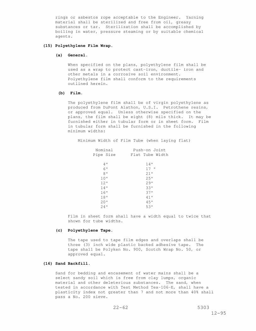
The polyethylene film shall be of virgin polyethylene asproduced from DuPont Alathon, U.S.I. Petrothene resins,or approved equal. Unless otherwise specified on theplans, the film shall be eight (8) mils thick. It may befurnished either in tubular form or in sheet form. Filmin tubular form shall be furnished in the followingminimum widths:
Minimum Width of Film Tube (when laying flat)
Nominal Push-on JointPipe Size Flat Tube Width
4" 14"6" 17 "8" 21"
10" 25"12" 29"14" 33"16" 37"18" 41"20" 45"24" 53"
Film in sheet form shall have a width equal to twice thatshown for tube widths.
(c) Polyethylene Tape.
The tape used to tape film edges and overlaps shall bethree (3) inch wide plastic backed adhesive tape. Thetape shall be Polyken No. 900, Scotch Wrap No. 50, orapproved equal.
(16) Sand Backfill.
Sand for bedding and encasement of water mains shall be aselect sandy soil which is free from clay lumps, organicmaterial and other deleterious substances. The sand, whentested in accordance with Test Method Tex-106-E, shall have aplasticity index not greater than 7 and not more than 40% shallpass a No. 200 sieve.
23-62 530312-95
(17) Concrete.
All concrete shall be Class "A" conforming to the require-ments of Item 421, "Portland Cement Concrete", unless other-wise specified on the plans.
All forms shall be left in place unless the Engineer directsthat certain sections of the forms be removed.
(18) Grout for Prestressed Concrete Cylinder Pipe Joints.
(a) General.
Interior joint grout shall be mixed with as little wateras possible so that the grout will be very stiff butworkable. Exterior joint grout shall be mixed with wateruntil it has the consistency of thick cream.
Water shall have total dissolved solids less that 1000mg/l as measured in accordance with ASTM D 1888, MethodA; chloride ions less than 100 mg/l for slurry and mortarcure, as measured in accordance with ASTM D 512; pHgreater than 6.5 as measured in accordance with ASTM D1293.
(b) Nonshrink Grout.
The nonshrink grout shall meet the followingrequirements:
It shall be a pre-blended factory-packaged materialmanufactured under rigid quality control, suitable foruse in the joints of prestressed concrete cylinder pipe.
It shall contain nonmetallic natural aggregate and shallbe nonstaining and noncorrosive.
It shall conform to the requirements of the Corps ofEngineers' Nonshrink Grout Specification CRC C-621.
It shall be suitable for use in contact with potablewater supply.
It shall be highly flowable so that the joint wrapperaround the exterior pipe joint can be filled withoutleaving any voids or trapped air. It shall be capable ofbeing placed with a plastic consistency in the interiorpipe joint.
It shall be nonbleeding and nonsegregating at a fluidconsistency.
It shall not contain any chlorides or additives which maycontribute to corrosion of the steel pipe.
It shall be free of gas-producing or gas-releasingagents.
It shall resist attack by oil and water.
"EUCON N-S Grout" as manufactured by Euclid Chemical
24-62 530312-95
Company, Cleveland, Ohio, or approved equal shall beconsidered acceptable.
The nonshrink grout shall be mixed, placed and cured inaccordance with the manufacturer's instructions andrecommendations.
The manufacturer of the nonshrink grout shall makeavailable, at no additional cost, and upon 72 hoursnotice, the services of a qualified representative to aidthe Contractor in assuring proper use of the productunder job conditions and shall be on site when theproduct is first used.
The grout shall have a minimum seven (7) day unconfinedcompressive strength of 2500 psi, and a minimum 28 dayunconfined compressive strength of 5000 psi. Strengthshall be tested in accordance with ASTM C109.
Joint wrappers shall have minimum width of nine (9)inches for 24 inch diameter pipe and 12 inches for largerdiameter pipe. The wrapper shall be hemmed at each edgeto allow threading with a minimum 5/8 inch wide steelstrap. Wrappers shall have a six (6) inch wide ethafoamstrip sewn circumferentially in the center of the nine(9) inch wide wrapper to resist backfill penetration intothe exterior joint recess.
All forms shall be left in place unless the Engineerdirects that certain sections of the forms be removed.
(19) Water Meter and Meter Vault.
(a) Pipe and Fittings.
All pipe and fittings shall be ductile iron or cast ironconforming with Article 2. Subarticles (3) and (4) ofthese specifications.
(b) Tapping Valves.
All tapping valves shall be standard non-rising stem (NRS)bronze double disc type water works valves conforming toAWWA C500. Unless otherwise specified on the plans eachvalve shall have a two (2) inch square operating nut,operating clockwise to open the valve. The inlet jointshall be flanged and drilled for Class 125 (ASA B16.1) andshall have machined projections. The outlet shall be astandard push-on or mechanical joint.
(c) Line Valves.
Line valves shall be standard NRS bronze double disc typevalves conforming to AWWA C500. Unless otherwisespecified on the plans each valve shall have a two (2)inch square operating nut, operating clockwise to open thevalve, and shall have push-on or mechanical joint hubs.
(d) Commercial Meter Valves for Meter Installation.
Commercial meter valves shall be identical with line
25-62 530312-95
valves except that they shall have Class 125 flanges, andbe equipped with handwheels operating counterclockwise toopen.
(e) Fire Flow Meter Valves for Meter Installation.
Fire flow meter valves shall be outside stem and yoke(OS&Y) bronze double disc valves (line valves only) andshall be factory mutual (FM) approved. Each valve shallhave Class 125 flanges and shall operate counterclockwiseto open.
(f) Turbine-Type Meter (Sizes 4-Inch through 10-Inch).
Meters shall be complete units constructed for continuousoperation and designed to conform with AWWA C701. Theyshall consist of the following individual assemblies:main case assembly, register and measuring chamberturbine.
The main case assembly shall be of copper alloy com-position with case bolts, and straightening vanes of non-corrosive material compatible with case material.
Register shall be standard straight-reading (odometertype) in U.S. gallons, with test sweep hand. The digitsshall be black in color with the lowest registering three(3) digits (below the 1000 gallon registration) ofcontrasting digit and background color. Meters thatrequire a direct-reading remote register system shall bein accordance with AWWA C706, and shall utilize a two (2)wire electrical signal transmission assembly.
Measuring chamber turbine shall be mounted in a horizon-tal position so that the water flow passes in a straight-through pattern in the meter casing and measuring chamberhousing.
The turbine rotor may be constructed of plastic material(thermoplastic polypropylene) or similar non-rubbermaterial having a specific gravity of approximately one(1) and shall be equipped with near frictionless repla-ceable bearings which rotate on a stationary replaceablestainless steel shaft. Replaceable thrust bearings mustbe provided in the turbine and shall work against asuitable thrust bearing positioned on the rotor shaft.
The manufacturer's meter serial number shall be stamped onthe outer case and on the outside of the register lid.Manufacturer's meter serial numbers shall be individualand shall not be duplicated.
Accuracy registration tests will be conducted by acertified testing facility approved by the Engineer on allmeters prior to installation.
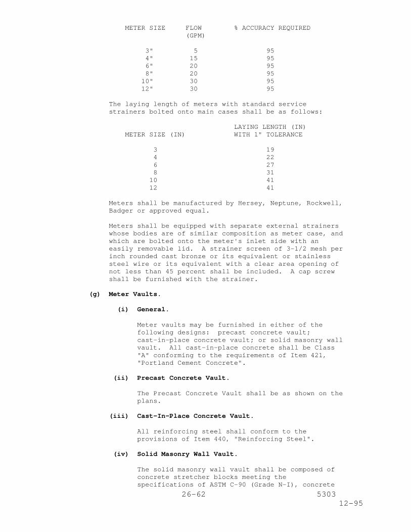
On the basis of flow tests using test equipment of acertified and approved testing facility, the followingaccuracy in percent of low-flow registration shall be theminimum acceptable for compliance with thesespecifications:
26-62 530312-95
METER SIZE FLOW % ACCURACY REQUIRED(GPM)
3" 5 954" 15 956" 20 958" 20 95
10" 30 9512" 30 95
The laying length of meters with standard servicestrainers bolted onto main cases shall be as follows:
LAYING LENGTH (IN)METER SIZE (IN) WITH 1" TOLERANCE
3 194 226 278 31
10 4112 41
Meters shall be manufactured by Hersey, Neptune, Rockwell,Badger or approved equal.
Meters shall be equipped with separate external strainerswhose bodies are of similar composition as meter case, andwhich are bolted onto the meter's inlet side with aneasily removable lid. A strainer screen of 3-1/2 mesh perinch rounded cast bronze or its equivalent or stainlesssteel wire or its equivalent with a clear area opening ofnot less than 45 percent shall be included. A cap screwshall be furnished with the strainer.
(g) Meter Vaults.
(i) General.
Meter vaults may be furnished in either of thefollowing designs: precast concrete vault;cast-in-place concrete vault; or solid masonry wallvault. All cast-in-place concrete shall be Class"A" conforming to the requirements of Item 421,"Portland Cement Concrete".
(ii) Precast Concrete Vault.
The Precast Concrete Vault shall be as shown on theplans.
(iii) Cast-In-Place Concrete Vault.
All reinforcing steel shall conform to theprovisions of Item 440, "Reinforcing Steel".
(iv) Solid Masonry Wall Vault.
The solid masonry wall vault shall be composed ofconcrete stretcher blocks meeting thespecifications of ASTM C-90 (Grade N-I), concrete
27-62 530312-95
brick meeting the specifications of ASTM C-55(Grade S-I), or common brick meeting thespecifications of ASTM C-32 (Grade MS or MM). Themortar shall be one (1) part Portland cement tothree (3) parts clean sharp sand. Lime may beadded, but shall not exceed 10 percent by weight ofPortland cement.
(v) Frame and Cover.
All steel shall be A-36. Cover plate shall be 1/4inch skid resistant raised pattern floor plate.Meter access door shall be made from the samematerial as cover plate. All welding shall beaccomplished in accordance with the provisions ofItem 441, "Steel Structures". Nondestructivetesting will not be required.
(20) Affidavit of Compliance.
Unless otherwise directed by the Engineer, the Contractor willbe required to furnish a manufacturer's affidavit of compliancefor each of the materials used in this project. The affidavitshall certify that factory inspection and all specified testshave been made and that the material furnished complies withthe requirements outlined herein.
(21) Cement Stabilized Backfill.
Cement stabilized backfill shall contain a minimum of ten (10)percent of portland cement per cubic yard of material as placedbased on the dry weight of the aggregate in accordance withTest Method Tex-120-E. The materials shall consist ofaggregate, portland cement, and water. Cement and water shallconform to the materials requirements of Item 421, "PortlandCement Concrete". Aggregate shall be sand, free fromdeleterious matter, with a plasticity index not greater thansix (6) when tested by Test Method Tex-106-E.
(22) Pressure Reducing Station.
All station piping, valves and fittings shall be new and unusedunless otherwise specified on the plans and shall be of thesame type used on the existing station.
Concrete shall be Class "A" conforming to Item 421, "PortlandCement Concrete".
Reinforcing steel shall conform to Item 440, "ReinforcingSteel".
A pressure reducing valve (PRV) with strainer shall be providedin the location and arrangement as shown on the plans. Thevalve body shall be ASTM A 48 cast iron or ASTM A 126, Class Bcast iron with 125 Class ANSI B16.1 flanges. The valve covershall be ASTM A 48 cast iron. All valve internals shall beType 303 stainless steel or B-62 bronze. All rubber partsshall be Buna-N. No leather parts shall be allowed. Resilientseat shall have a rectangular cross section.
Control tubing shall contain shutoff cocks with a "Y" strainer.
28-62 530312-95
The valve shall be equipped with a valve position indicator.
The valve shall be initially set in the field by an authorizedmanufacturer's representative. The downstream pressure shallbe set at 60 psi.
A Cla-Val Model 90-01, GA Industries Fig. 4500-D or approvedequal shall be provided.
A basket strainer upstream of the pressure reducing valve shallbe provided as shown on the plans. Strainer body shall bequick-opening type, fabricated steel construction with ANSIClass 150 flanges. The basket shall be Type 304 stainlesssteel.
A Hayward Model 90 or equal for PRV's 12 inches and smallershall be provided. A Hayward Model 510 or equal for PRV's 14inches or greater shall be provided.
3. Construction Methods.
(1) Excavation.
Excavation greater than five (5) feet in depth shall beprotected as specified in Item 402, "Trench ExcavationProtection" or Item 403, "Temporary Special Shoring".
(a) Trenches.
All water lines shall be constructed in open cut trencheswith vertical sides except in those locations where thepipe is to be jacked or placed in bored holes. The trenchshall conform to the dimensions shown in the excavationand backfill diagram.
Trenches shall be sheathed and braced to the extentnecessary to maintain the sides of the trench in a ver-tical position throughout the construction period. Inaddition, sheathing and bracing shall be placed asnecessary for the protection of adjacent propertyincluding structures, substructures and service lines ofpublic utility corporations. Adequacy of the sheathingand bracing shall be the responsibility of the Contractorbut will be subject to the approval of the Engineer. TheEngineer will determine what material is to remain in thetrench. When solid sheathing is required, the timbershall be cut off 18 inches below the ground beforebackfilling the trench.
The trench must be opened and excavated to the finishedgrade at all times for a distance of at least 50 feet inadvance of the last joint of pipe which has been placed.Water mains, to which the mains under construction are tobe connected, must be definitely located well in advanceof such connection to allow for possible adjustment ofalignment and/or grade.
Water mains shall be constructed in dry trenches. If itbecomes necessary to employ well pointing, additionalsheathing, or to provide a concrete seal in the bottom ofthe trench to accomplish this objective, this additional
29-62 530312-95
work shall be performed by the Contractor withoutadditional compensation.
Where it is necessary to excavate trenches adjacent toimproved property, the Contractor will be required to takenecessary precautions so as not to damage or impair thatproperty. Where it is necessary to disturb grass, shrubs,driveways, etc., the Contractor will be required torestore such improvements to their original condition.
(b) Existing Streets.
Unless otherwise shown on the plans, all existing streetsshall be open cut.
Where water line construction necessitates cutting throughexisting streets outside the limits of new streetconstruction, said streets shall be replaced in kind inaccordance with the appropriate specifications in theproposal or as directed by the Engineer. There shall be aminimum cut-back of 12 inches on each side of andimmediately adjacent to the water main trench prior toreplacing concrete and/or blacktop paving. An additionalwidth will be required for unstable conditions.
Where, in the opinion of the Engineer, it is necessary tomaintain traffic across a trench, the Contractor will berequired to construct temporary bridges as necessary tofacilitate the movement of traffic.
At locations where the proposed water main parallels theedge of an existing permanent pavement (i.e., concretepavement, concrete base with asphalt surface, etc.), andis three (3) feet or less from the edge of that pavement,the trench shall be protected with timber sheathing andbracing. Bracing shall be left in place at intervals notto exceed five (5) feet.
The street surface adjacent to the trench must be keptfree of surplus spoil. Construction materials shall beplaced at locations that will minimize interference withthe traveling public.
Not more than two (2) street intersections shall be closedat any one time unless authorized by the Engineer inwriting.
(2) Jacking, Boring or Tunneling Pipe.
(a) General.
Jacking, boring or tunneling for water mains shall beperformed at the locations shown on the plans and at suchother locations specifically designated by the Engineer.
Unless otherwise shown on the plans, casing pipe shallconform to the requirements of Section 2.(2)(b) of thisspecification.
30-62 530312-95
(b) Jacking.
Jacking shall conform to the requirements of Item 476,"Jacking, Boring or Tunneling Pipe".
(c) Boring.
Boring shall conform to the requirements of Item 476,"Jacking, Boring or Tunneling Pipe".At all locations where water pipes cross underneathdriveways (of 16 feet or less in width) and/or sidewalks,pipe shall be installed in tight fitting augered holes.
At locations where the centerline of the proposed watermain is 10 feet or less from the centerline of an eight(8) inch diameter or larger growing tree, the pipe shallbe placed in a tight fitting augered hole. The bored holeshall extend at least four (4) feet beyond each side ofthe tree.
(d) Tunneling.
Tunneling shall conform to the requirements of Item 476,"Jacking, Boring or Tunneling Pipe".
(3) Handling of Pipe and Accessories.
(a) General.
Pipe, fittings, valves and accessories shall be unloadedat the point of delivery and hauled to the site of theproject. The material shall be distributed opposite ornear the place where it is to be laid in the trench.Under no circumstances shall the materials be dropped.Pipe handled on skidways shall not be skidded or rolledagainst pipe already on the ground.
All pipe and fittings shall be loaded, transported,unloaded and otherwise handled in a manner and by methodswhich will prevent damage of any kind thereto. Pipe shallbe handled and transported with equipment designed,constructed and arranged to prevent damage to the pipe,lining and coating. Bare chains, hooks, metal bars, ornarrow skids or cradles will not be permitted to come incontact with the coatings. Spiders shall be installed bymanufacturer at joint ends of fittings.
Pipe shall be hoisted from the trench side into the trenchby means of a sling of smooth steel cable, canvas,leather, nylon or similar material.
At all times during pipe construction operations, theContractor shall use every precaution to prevent injury tothe pipe, protective linings and coatings.
When pipe is stacked, pipe is to be packaged on timbers.Protective pads are to be placed under banding straps atthe time of packaging.
When fork trucks are used to relocate pipe, the forks
31-62 530312-95
shall be padded using carpet or some other suitable typeof materials. When pipe is relocated using a crane orbackhoe, nylon straps and not chains or cables shall beused around the pipe for lift.
Pipe shall not be lifted using hooks at each end of thepipe.
Any damage to the pipe or the protective lining andcoating from any cause during the installation of thepipeline and before final acceptance by the purchasershall be repaired at the expense of the laying contractoras directed by the Engineer and in accordance with theapplicable standards.
(b) Cast-Iron or Ductile-Iron Pipe, Valves and Fittings.
Cast-iron or ductile-iron pipe, valves and fittings shallbe handled in such a manner that the coating and liningwill not be damaged. If, however, any part of the coatingor lining is damaged, the repair shall be made by theContractor at his expense and in a manner satisfactory tothe Engineer.
(c) Asbestos-Cement Pipe.
Asbestos-cement pipe shall be handled in such a manner asto avoid damage to the machined ends. However, if thepipe is damaged to such an extent that it cannot berepaired to the satisfaction of the Engineer, it shall bereplaced at the Contractor's expense.
(d) Polyvinyl Chloride Pipe.
Plastic pipe should be stored so as to prevent damage bycrushing or piercing. If stored for any length of time,it should be under cover and not in direct sunlight inaccordance with the manufacturer's specifications. Careshould be taken to protect the pipe from excessive heat orharmful chemicals.
(4) Pipe Cutting.
Pipe, 12 inches in diameter and smaller, shall be cut withstandard wheel pipe cutters. Each cut shall be at right anglesto the axis of the pipe and shall be filed or ground toresemble the spigot end of the pipe as manufactured.
(5) Lowering of Pipe and Accessories into Trench.
Implements, tools and facilities satisfactory to the Engineershall be provided and used by the Contractor for the safe andefficient execution of the work. All pipe, fittings, valvesand hydrants shall be carefully lowered into the trench withsuitable equipment that will prevent damage to the materialsand their protective coatings and linings. Under nocircumstances shall water main materials be dropped or dumpedinto the trench.
32-62 530312-95
(6) Defective or Damaged Material.
Pipe and accessories shall be inspected for defects prior tobeing lowered into the trench. Any defective, damaged, orunsound material shall be repaired or replaced as directed bythe Engineer.
Should a damaged piece of pipe furnished by the Contractor beplaced in the water main, the Contractor shall furnish at hisexpense all labor and materials required for removing andreplacing the defective pipe and restoring the street to itscondition just prior to the failure of the pipe. Should theContractor damage the pipe after installation, the Engineer maypermit the damaged section to be cut from the length unless itis the opinion of the Engineer that the entire length wasdamaged. The cost and replacement of broken pipe will be atthe expense of the Contractor.
(7) Cleaning of Pipe and Accessories.
All lumps, blisters and excess coating shall be removed fromthe bell and spigot ends of cast-iron pipe, ductile-iron pipe,asbestos cement pipe, valves, hydrants and fittings. Theoutside of the spigot and the inside of the bell shall be wirebrushed and wiped clean, dry and free from oil and greasebefore the pipe is laid.
All foreign matter or dirt shall be removed from the interiorof all water pipe and accessories and from the mating sur-faces of the joints prior to lowering the material into thetrench. The pipe and accessories shall be kept clean duringand after laying by means approved by the Engineer.
Cleaning solutions, detergents, solvents, etc. should be usedwith caution when cleaning PVC pipe.
(8) Laying of Pipe.
For the work of laying the pipe, the Contractor shall employonly workmen who are skilled and experienced in laying pipe ofthe type and joint configuration being furnished. It shall bethe responsibility of the Contractor to provide watertight pipeand pipe joints. Pipe shall be laid with bell ends facing inthe direction of laying, unless otherwise directed by theEngineer.
Pipe shall be laid to the lines and grades shown on thedrawings. To ensure proper placement, the Contractor shall useadequate surveying methods and equipment and shall employpersonnel competent in the use of this equipment. The pipeshall not deviate from the horizontal and vertical alignment asindicated on the drawings by more than 0.10 foot without priorconsent of the inspector. The Contractor shall measure andrecord the "as-built" horizontal alignment and vertical gradeat a maximum of every 50 feet on the on-site recorded drawings.
Pipe trenches shall be kept free of water which might impairpipe laying operations at all times during laying operations.Holes for bells shall be of ample size to prevent bells formcoming in contact with the subgrade. Pipe trenches shall becarefully graded so as to provide uniform support along the
33-62 530312-95
bottom of pipe.
Not more than 50 feet of pipe shall be laid in the trench aheadof backfilling operations and if pipe laying operations areinterrupted for more than 48 hours, all pipe laid in the trenchshall be covered simultaneously on each side of the pipe toavoid lateral displacement of the pipe and damage to thejoints. If adjustment of the position of a length of pipe isrequired after it has been laid, it shall be removed and re-laid in accordance with these specifications and at theContractor's expense. After all pipe laying and joiningoperations are completed, the inside of the pipe shall becleaned and all debris removed.
Care shall be taken to prevent damage to the coating whenplacing backfill. Backfilling shall be in accordance withSubarticle 3.(10) Backfilling.
Pipe shall be laid in a straight line unless otherwise shown orapproved by the Engineer. Maximum pipe joint deflection, ifpermitted, shall not exceed the pipe manufacturer'srecommendation.
Long radius curves, either horizontal or vertical, may be laidwith standard pipe by deflections at the joints. If the pipeis shown curved, no special fittings are shown. The curves canbe made by deflection of the joints with standard lengths ofpipe as approved by the Engineer.
Where field conditions require deflection of curves notanticipated by the drawings, the Engineer will determine themethods to be used. No additional payment will be made forlaying pipe on curves as shown, nor for field changes involvingstandard lengths of pipe deflected at the joints.
When rubber gasketed pipe is laid on a curve, the pipe shall bejointed in a straight alignment and then deflected to thecurved alignment.
The Contractor will not be permitted to have, at any time, over1,000 feet of pipe on publicly used streets ahead of the trenchexcavating machine. Permission, in writing, must be obtainedfrom the owner or his agent prior to placing any materials orequipment on private property.
Regardless of the type of pipe being used, a sand bedding shallbe placed in the bottom of the trench and compacted to a depthof six (6) inches. The bedding shall be carefully graded andall bell holes excavated.
Pipe shall be laid with bell ends facing in the direction oflaying, unless otherwise directed by the Engineer. Whenever itis necessary to deflect pipe in order to avoid obstructions orto form long-radius curves, the amount of deflection shall notexceed the limits recommended by the manufacturer. If thedeflection exceeds the maximum recommended by the manufacturer,the Contractor shall be required to remove the entire portionof the deflected pipe section and install new pipe as directed
34-62 530312-95
by the Engineer. This work will not be paid for but will be atthe Contractor's entire expense.
Assessment of deflection may be measured by the Engineer at anylocation along pipe. Arithmetical averages of the deflectionor similar average measurement methods will not be deemed asmeeting the intent of the standard.
The pipe, valves, hydrants and fittings shall be adjusted so asto be at their proper locations and each joint shall beprepared as specified in Subarticle 3.(9), "Joining of Pipe andAccessories". As each joint of pipe is laid in the trench, thespigot end shall be centered in the bell of the previously laidpipe; the pipe shall be forced home and brought to correct lineand grade. Each length of pipe shall rest on the bottom of thetrench throughout its entire length.
Whenever the laying of pipe is discontinued for the day or foran indefinite period, a cap or plug shall be tightly yarned inthe end of the last pipe laid to prevent the intrusion ofwater. When water is excluded from the interior of asbestos-cement pipe or polyvinyl chloride pipe, enough backfill shallbe placed on the pipe to prevent floating. The Contractorshall schedule his work to prevent the possibility offloatation. Any pipe that has floated shall be removed fromthe trench and relaid as directed by the Engineer.
When PVC pipe has been assembled on top of the trench, it shallbe allowed to cool to ground temperature before backfilling toprevent pull out due to thermal contraction.
For Prestressed Concrete Cylinder Pipe, the manufacturer shallprovide the services of a service representative for a periodof not less than two (2) weeks at the beginning of the actualpipe laying operations to advise the Contractor in all aspectsof installation including but not limited to handling andstoring, cleaning and inspecting, coatings and linings repairs,and general construction methods as to how they may affect thepipe.
(9) Joining of Pipe and Accessories.
(a) Cast-Iron Pipe, Ductile-Iron Pipe, Valves, Hydrants andFittings.
Following the thorough cleaning of the inside of the belland the outside of the spigot, the circular rubber gasketshall be flexed inward and inserted in the gasket recessof the bell. A thin film of gasket lubricant shall beapplied to either the inside surface of the gasket or thespigot end of the pipe or both. Gasket lubricant shall beas supplied by the pipe manufacturer and shall be subjectto approval by the Engineer.
Pipe and accessories that are not furnished with a depthmark shall be marked before assembly to assure that thespigot end is inserted to the full depth of the joint.
(b) Asbestos-Cement Pipe and Accessories.
The machined ends of pipe to be jointed, the coupling
35-62 530312-95
grooves, and rubber rings shall be cleaned immediatelybefore assembly. The joint shall be assembled in themanner recommended by the manufacturer. Each pipe jointshall be sealed with a coupling consisting of an asbestos-cement sleeve and two rubber rings. The location of fieldassembled rubber rings shall be checked with a suitablegage to verify that rubber rings are in the requiredposition.
When mechanical joints are used at the fitting, the lengthof the pipe fitted into the bell of the fitting shall notbe more than 3 feet 3 inches in pipe of 6 inch diameterand smaller, or 6 feet 6 inches, in pipe of 8 inchdiameter and larger.
When a rubber ring is used to make the seal, andflexibility is provided by a grooved design profilesimilar to that of the coupling used to join pipe betweenfittings, up to a full 13 foot length may be used.
When mechanical joints are used, the pipe connecting anytwo (2) valves or fittings shall be in two (2) or morelengths jointed with one (1) or more couplings to provideflexibility. If a flexible seal is used, a single 13foot or shorter length may be used to connect the two (2)fittings without any intermediate coupling.
(c) Polyvinyl Chloride Pipe and Accessories.
Plastic pipe shall be joined in accordance with theinstructions furnished by the manufacturer. Pipe joinedusing solvent cementing techniques shall not be handled orinstalled in the trench until after the joints aresufficiently "cured" to prevent weakening the joint.
Lubrication for rubber-gasketed joints shall be watersoluble, non-toxic, non-objectionable in taste and odorimparted to the fluid, non-supporting of bacteria growth,and have no deteriorating effect on PVC or the rubbergaskets.
(d) Welded Joints for Steel Pipe.
If the joints are to be field welded for thrust restraint,the joints shall receive a full-fillet single lap-weldedslip type weld either inside or outside, or a buttweldtype weld, with a backing strap, in accordance with AWWAC206. Either automatic or hand welders may be used at theContractor's option. Prior to work being started, theContractor shall provide proof of certification ofqualification for all welders employed on the project forall the type of work procedures and positions involved.Qualification shall be in accordance with AWWA C206.Complete penetration of deposited metal with base metalshall be assured. The inside fittings and joints must befree from globules of weld metal which would restrict flowor become loose.
For 36-inch diameter and larger pipe, the joints are to befurnished with trimmed spigots (Carnegie shaped jointonly) and interior welded. For 30-inch diameter and
36-62 530312-95
smaller pipe, the joints to be welded are to be exteriorwelded.
On bell-and-spigot lap-welded slip joints, deflection maybe taken at the joint by pulling a joint up to 3/4 inch,as long as 1-1/2 minimum lap is maintained. The bell orspigot end may be miter cut to take deflections up to five(5) degrees as long as proper joint tolerances aremaintained. Only one (1) end may be miter cut. Miter endcuts of both ends of butt-welded joints may be used forjoint deflections of up to 2-1/2 degrees.
Piping and equipment shall be aligned so that no part isoffset more than 1/8 inch. All fittings and joints shallbe set square and true, and the alignment shall bepreserved during welding operations. For butt-weldedjoints, The alignment of the butting ends shall be such asto minimize the offset between surfaces. For pipe of thesame nominal wall thickness, the offset shall not exceed1/16 inch. Line-up clamps shall be used for this purpose;however, care must be taken to avoid damage to linings andcoatings.
During welding, the coal tar epoxy lining shall beprotected by draping an 18 inch wide strip of heat-resistant material over the top half of pipe on each sideof lining holdback to avoid damage to the lining by thehot splatter. If external welding is used or required,the tape coating shall be similarly protected.
Welding rods shall be of a type compatible with the metalto be welded to obtain the strongest bond, E-70XX.
The metal shall be deposited in successive layers so thatthere will be at least two (2) passes or beads forautomatic welding and three (3) passes or beads for manualwelding in the completed weld.
On all welds, not more than 1-1/4 inch of metal shall bedeposited on each pass. Each individual pass, includingthe final one, shall be thoroughly cleaned by wirebrushing and/or hammering to remove dirt, slag, or flux.
Welding shall not be performed under any weather conditionthat would impair the strength of the weld, such as wetsurface, rain or snow, dust or high winds, unless the workis properly protected.
Tack welds, if used must be of the same material and madeby the same procedure as the completed weld. Otherwise,tack welds shall be removed during welding operation.
Dirt, scale and other foreign matter shall be removed frominside piping before tying in sections, fittings orvalves.
The Contractor shall have an independent certified testinglaboratory, approved by the Engineer, to perform weldtests on all portions of the job. The cost of suchtesting shall be included in the contract unit bid pricefor the water main. Copies of all test reports shall be
37-62 530312-95
furnished to the Engineer for review. Testing shall bemade by magnetic particle test methods for lap welds or byX-ray methods for butt welds, for 100 percent of all jointwelds. If a defective weld is revealed, the cost of therepair and the retesting of the repaired weld will be paidfor by the Contractor. The Engineer shall have the fulland final decision as to the suitability of all weldstested.
(e) Flanged Joints for Steel Pipe.
Prior to the installation of bolts, the flange jointsshall be accurately centered and aligned to preventmechanical prestressing of flanges, pipe and equipment.Bolt holes shall be aligned to straddle the vertical,horizontal or north-south center line. The inclination ofthe flange face from true alignment shall not exceed 3/64inch per foot.
For inline flange joints 12 inches in diameter and greaterand butterfly valve flanges, Pyrox LineBacker Type Ephenolic gaskets as manufactured by Pipeline Seal andInsulator Inc., or approved equal shall be used.
Full-face gaskets for all other flanged joints not listedabove shall be used. Cloth-inserted rubber gasketmaterial, 1/8-inch thick in accordance with AWWA C207shall be provided. Gaskets shall be factory cut to properdimensions.
Galvanized or black ANSI nuts and bolts shall be used tomatch the flange material. Cadmium-plated steel nuts andbolts shall be used on underground flanges. Bolts shallbe tightened progressively to prevent unbalanced stress.Bolts shall be drawn tight to ensure proper seating ofgaskets.
The Contractor shall pay particular attention toprocedures used in tightening and torquing flanged joints.Improper methods may result in leakage and necessitatecorrective measures. The Contractor should followrecommended industry standards and guidelines as set forthby the various fabricators and manufacturers.
(f) Rubber Gasketed Bell-and-Spigot Joints For Use OnPrestressed Concrete Cylinder Pipe.
Rubber gasket material for rubber gasketed bell and spigotjoints shall be in accordance with AWWA C301. After therubber gasket is placed in the spigot groove of the pipe,the rubber gasket cross section shall be equalized byinserting a tool or bar such as a large screwdriver underthe rubber gasket and moving it around the periphery ofthe pipe spigot. The gaskets shall be lubricated with anontoxic water-soluble lubricant before the pipe units arejointed. The pipe units shall be fitted together in amanner to avoid twisting or otherwise displacing ordamaging the rubber gasket. After the pipe sections arejoined, the gaskets shall be checked with a feeler gaugeto ensure that no displacement of the gasket has occurred.If displacement has occurred, the pipe section shall be
38-62 530312-95
removed and the joint shall be remade as if for new pipe.Remove the old gasket, inspect for damage and replace ifnecessary before remaking the joint.
(g) Welded Joints For Use On Prestressed Concrete CylinderPipe.
For welded joints restrained joints shall be welded to thelengths called out on the contract or accepted shopdrawings. Lap-welded slip joints or single butt-weldedjoints shall be performed in accordance with AWWA C206,latest edition. Either automatic or hand welders may beused at the Contractor's option. Prior to work beingstarted, the Contractor shall provide proof ofcertification of qualification for all welders employed onthe project for the type of work procedures and positionsinvolved. Qualification shall be in accordance with AWWAC206. Ensure complete penetration of deposited metal withbase metal. The inside of fittings and joints must befree from globules of weld metal which would restrict theflow or become loose. Do not use mitered joints.
For 36-inch and larger pipe, the joints to be welded areto be furnished with trimmed spigots and shall be interiorwelded. For 30-inch and smaller, the joints to be weldedare to be exterior welded.
Piping and equipment shall be aligned so that no part isoffset more than 1/8 inch. All fittings and joints shallbe set square and true, and the alignment shall bepreserved during welding operations. The use of alignmentrods inside the pipe shall be prohibited.
Welding rods shall be of a type compatible with the metalto be welded to obtain the strongest bond, E-70XX.
The weld metal shall be deposited in successive layers sothat there will be at least two (2) passes or beads, forautomatic welding , and three (3) passes or beads formanual welding, in the completed weld. On all welds, notmore than 1/4 inch of metal shall be deposited on eachpass. Each individual pass, including the final one,shall be thoroughly cleaned by wire brushing and/orhammering to remove dirt, slag or flux.
Welding shall not be performed under any weather conditionthat would impair the strength of the weld, such as wetsurface, rain or snow, dust or high winds, unless the workis properly protected.
Tack welds, if used, must be of the same material and madeby the same procedure as the completed weld. Otherwise,tack welds shall be removed during welding operation.
Dirt, scale and other foreign matter shall be removed frominside piping before tying in sections, fittings orvalves.
The Contractor shall have an independent certified testinglaboratory, approved by the Engineer, to perform weldtests on any portion of the job. The cost of such testing
39-62 530312-95
shall be included in the contract unit price bid for thewater main. Copies of all test reports shall be furnishedto the Engineer for review. Testing shall be made bymagnetic particle test methods for lap welds or by X-raymethods for butt welds for 100 percent of all joint welds.If a defective weld is revealed the cost of the repair andthe retesting of the repaired weld will be paid for by theContractor. The Engineer shall have the full and finaldecision as to the suitability of all welds tested.
(h) Flanged Joints For Use On Prestressed Concrete CylinderPipe.
Prior to the installation of bolts, the flanged jointsshall be accurately centered and aligned to preventmechanical prestressing of flanges, pipe and equipment.Bolt holes shall be aligned to straddle the vertical,horizontal or north-south center line. The inclination ofthe flange face from true alignment shall not exceed 3/64inch per foot.
For inline flange joints 12 inches in diameter andgreater, and at butterfly valve flanges, Pyrox 10 Type "E"LineBacker phenolic gaskets as manufactured by PipelineSeal and Insulator, Inc., or approved equal shall be used.
Full-face gaskets for all other flanged joints not listedabove shall be used. Cloth inserted rubber gasketmaterial, 1/8 inch thick in accordance with AWWA C207shall be provided. Gaskets shall be factory cut to properdimensions.
Galvanized or black ANSI nuts and bolts shall be used tomatch the flange material. Use cadmium-steel nuts andbolts on underground flanges. Bolts shall be tightenedprogressively to prevent unbalanced stress. Bolts shallbe drawn tight to ensure proper seating of gaskets.
The Contractor shall pay particular attention toprocedures used in tightening and torquing flanged joints.Improper methods may result in leakage and necessitatecorrective measures. The contractor should followrecommended industry standards and guidelines as set forthby the various fabricators and manufacturers.
(i) Joint Grouting For Use On Prestressed Concrete CylinderPipe.
The grout shall be mixed in a machine mixer except whenless than 1/2 cubic yard will be used. Where less than1/2 cubic yard is required, grout may be hand mixed. Onlythe amount of grout needed for immediate use shall bemixed. Grout that has set shall be discarded.Retempering of grout by any means is not permitted.
Grout shall be prepared in small batches so as to preventstiffening before it is used. Any grout which has becomeso stiff that proper placement cannot be assured shall bediscarded. Grout for filling grooves shall be of suchconsistency that it will adhere to the ends of the pipe.
40-62 530312-95
Surface preparation shall involve the removal of alldefective concrete, laitance, dirt, oil, grease and otherforeign material from concrete surfaces by brush,hammering, chipping or other similar means, until a sound,clean concrete surface is achieved. Rust and all foreignmaterials shall be removed from all metal surfaces thatwill contact with the grout.
Refer to Item 420, "Concrete Structures", for specialprecautions to be used for concreting during periods ofhot or cold weather.
The completion of the outside joint operations andbackfilling of the pipe trenches shall follow pipelayingoperations as closely as practical.
Prior to filling the joint with grout, the outside spaceshall be flushed with water so that the surfaces of thejoint in contact with the grout filling will be thoroughlycleaned and moistened before the grout is poured.
After each joint is fully engaged, a joint grout bandconsisting of an ethyfoam diaper material shall be securedaround the pipe, over the exterior joint recess in such amanner that there will be essentially no leakage of grout.For lined prestressed concrete cylinder pipe, there shallbe no additional bedding or backfill material placed oneither side of the pipe until after the grout band isfilled and the grout has mechanically stiffened.
The band shall be completely filled with grout in one (1)operation by filling from one (1) side only until thegrout rises on the opposite side, and then rodded oragitated on both sides of the pipe alternately to settlethe grout. The grout shall then not be agitated for atleast 15 minutes to allow excess water to seep throughtthe joint band and to allow the grout to mechanicallystiffen. After this period, more grout shall be added ifnecessary to fill the joint completely.
The gap at the top of the joint band shall be protectedfrom backfill by allowing the grout to stiffen, or bycovering with a structurally protective material. Theband shall not be removed from the joint.
For 36-inch and larger diameter pipe, once the backfillhas been placed and compacted up to the natural groundsurface, pavement or subgrade, the inside joint spaceshall be cleaned and the joint surfaces shall bethoroughly wetted before being filled with stiff groutwhich shall be trowelled smooth and flush with the insidesurfaces of the pipe.
For 30-inch and smaller pipe, prior to backfill beingplaced and compacted, the inside joint recess shall befilled immediately prior to placing the pipe together by"buttering" the bell end with grout. After the joint isengaged, the joint grout shall be finished off smooth andclean as follows:
A swab as approved by the Engineer, shall be used for pipe
41-62 530312-95
20 inches and smaller in diameter.
For the 24-inch diameter pipe and larger, joints shall befinished with a hand trowel.All improperly cured or otherwise defective grout shall beremoved and replaced by the Contractor at the Contractor'sexpense. The Engineer reserves the right to test thegrout strength at random.
When prestressed concrete cylinder pipe is installed in atunnel or encasement pipe and clearance within the casingdoes not permit the outside grout to be placed in thenormal manner, a flexible sealer, such as Flex Protex orapproved equal, shall be applied to the outside of thejoint prior to joint engagement. The surfaces receivingthe sealer shall be cleaned and primed in accordance withthe manufacturer's recommendation. Sufficient quantitiesof sealer shall be applied to assure complete protectionof all steel in the joint area. The interior of the jointshall be filled with grout as specified after jointclosure.
Grouting of the inside joint space for 36-inch diameterpipe and larger shall be accomplished at the end of eachwork day. Contractor must obtain written acceptance fromthe Engineer of the inside joints before proceeding withthe next day's pipe laying operation.
(10) Backfilling.
(a) Sand Backfill.
Following completion of the pipe joints being made up andinspected, sand backfill shall be placed along both sidesof the pipe equally, in uniform layers not exceeding six(6) inches in depth (loose measurement), wetted ifrequired, and thoroughly compacted. Backfilling andcompaction shall continue in this manner to the minimumelevation shown in the excavation and backfill diagram.Care shall be taken to see that no dirt, clods or trenchsides are allowed to fall and/or rest against the pipeprior to completion of the sand encasement.
(b) Earth Backfill.
The Contractor will be required to backfill all trenchesin accordance with the requirements of Item 400,"Excavation and Backfill for Structures", except formeasurement and payment.
The backfill and clean-up of each section of main, i.e.,from valve to valve, shall begin immediately upon thecompletion of the hydrostatic test and shall continueuntil a final and complete clean-up of the section isobtained. Any portion of the trench which is left open inexcess of that required to facilitate hydrostatic testingmay be ordered closed by the Engineer.
Surplus excavated materials are to be used in theembankments or disposed of as directed by the Engineer.
42-62 530312-95
(11) Valves and Fire Hydrants.
Each valve and fire hydrant must be completely closed whenplaced in the pipe line.
Each hydrant shall be set at the location and grade indicatedby the stakes and shall be plumbed and braced. If the barrelof a hydrant is to pass through a concrete slab, a piece of1-inch thick preformed bituminous expansion joint materialshall be fitted closely around the section of the barrelpassing through the concrete.
(12) Fittings.
The fittings on small mains shall be braced with short piecesof 2-inch galvanized pipe as directed by the Engineer.
Each cast-iron plug installed under this contract shall bebraced by a standard pipe clamp, a 3 foot nipple of the samediameter pipe as the nearby sections of mains, and a block ofconcrete. Pipe clamps for 4-inch through 12-inch water mainsshall be Underwriters approved for underground water servicepiping. Pipe clamps for water mains 16-inch and larger shallconform to details shown on the plans.
(13) Boxes for Valves.
The cast-iron or ductile iron or PVC pipe or shall be cut toproper length and the box shall be assembled and braced in aver- tical position in accordance with details shown on theplans. Butterfly valves for sizes 30-inch and larger willrequire man- holes to be constructed over the operators.
(14) Wet Connections.
The Contractor shall make the wet connections, under thedirection of the Engineer, in such a manner and at such hoursas to minimize inconvenience to the public. When the existingmains have been cut or a plug removed for a connection, thework of making the connection shall progress withoutinterruption until complete.
Whenever the Contractor desires to proceed with a wet connec-tion without a complete shut-off, there will be no extra com-pensation for damages or extra work resulting from theincomplete shut-off.
The utility owner shall operate all gate valves in the existingsystem and in sections of completed mains which have beenplaced in service.
Wet connections which are 2-inch or smaller are sometimesreferred to on the plans as 2-inch standard connections orgooseneck connections. Items which may be necessary tocomplete these types of wet connections include corporationcock, saddle, copper tubing, brass fittings and 2-inch valves.These connections are not to be used or construed as any partof a 2-inch service line.
43-62 530312-95
(15) Polyethylene Film Wrap.
When specified on the plans, cast-iron and/or ductile-iron pipe(including fittings and other appurtenances) shall be wrappedwith a polyethylene film. Fire hydrants need not be wrapped.
(a) Tube Type Wrap.
When the polyethylene film is supplied in tubular form, itshall be installed on the pipe prior to placing the pipein the trench and in the following manner:
Elevate the spigot end of the pipe; brush mud and debrisfrom the pipe, and slip a length of film (approximatelytwo (2) feet longer than the joint of pipe) over the jointof pipe. Wrap the film tightly around the spigot end,leaving about one foot extending beyond the end of thepipe, and tape the edge down lightly with polyethylenetape.
When the joint of pipe is picked up for placing in thetench, remove any remaining mud, clay or debris. Insertthe spigot end into the bell end of the joint previouslyplaced, push home, and release the pipe into the trench.Pick up the pipe joint at the bell, slide the film to apoint back of the bell, and prepare a bell hole.
When the next joint is laid, pull the film about three (3)feet beyond the bell so as to overlap the film attached tothe spigot of the new pipe joint. Wrap the film byfolding it longitudinally and tape securely in place toprevent damage during backfill. Do not tape the end thathas just been slipped over the last bell but bind it withtwine or other approved material.
At each corporation, draw the loose material up around thecorporation base and seal it with tape to insulate the two(2) dissimilar metals.
Wrap all fittings and fire hydrant leads, and tape or bindthe wrap with heavy twine. Fittings, such as bends andreducers, shall be wrapped similarly to the methodoutlined above. Specials, such as valves, tees, crosses,etc., shall be wrapped by splitting, tucking andoverlapping the polyethylene tube, then closing the fieldmade splices with the required tape. Material to coverthe valves may be acquired from excess overlappingpolyethylene tubing on adjacent pipe joints. Thepolyethylene tubing should be drawn over the bell of thepipe on either side and insulated with field made seams asdescribed above. All fittings and specials that requireconcrete blocking shall be completely wrapped prior toplacing concrete.
(b) Sheet Type Wrap.
For sheet type wrap, the wrap may be applied around thepipe either prior to or after pipe has been positioned inthe trench. "Above ground" installation shall be similarto that described above for tubular installation. "Intrench" installation shall also be made in a manner
44-62 530312-95
similar to that described in Section 3.(15)(a) except thatno dirt or other deleterious matter shall be allowedbetween the pipe barrel or bell and the film wrap. Filmwrap material shall be clean and free of mud, dirt orother undesirable material prior to placing around thepipe or fittings. In either case, one end of thepolyethylene film shall be tightly taped to the pipe one(1) foot away from the spigot end of the joint of pipe;the wrap shall be extended along the pipe length and shalloverlap the end of the next joint wrap. At this point thewrap will NOT be taped but bound tightly to the pipe withtwine.
(c) Bore Section Installation.
Cast-iron or ductile-iron pipe shall first be wrapped inpolyethylene tubing or sheet; the excess material shall belapped over to form a close fit around the barrel of thepipe. The wrap shall then be carefully bound in placeusing 1 inch x 2 inch or 1 inch x 4 inch lumber or similarmaterials and plastic binding bands at maximum one (1)foot intervals. The material shall be taped approximatelyone (1) foot from spigot end with approximately three (3)feet left to lap over the next joint of pipe. Althoughthere is no foolproof way of installing polyethylenewrapped pipe in bored holes, special care shall beexercised in seeing that the best possible job is achievedunder the prevailing circumstances. Alternate methods maybe permitted subject to the approval of the Engineer.
(16) Painting Steel Pipe and Structures.
(a) General.
The Contractor will be required to take adequate pre-cautions to prevent spattering adjacent structures withpaint or otherwise marring the subject structures whilethe pipe is being installed and/or painted.
Following the cleaning of the pipe by blasting, the pipeshall be painted with the applicable primer or coal tarcoating the same day. No paint shall be applied when theair temperature is below 40 F or during foggy or wetweather.
Lead primer and/or paint will not be allowed on thisproject.
The interior and exterior surfaces of all steel pipe andhardware furnished under this specification shall be givenprotective coatings as follows:
(B) External Coating Systems for Buried Steel Pipe.
(i) General.
Pipe shall be supplied with either tape coatings orcement-mortar coatings as specified herein.
45-62 530312-95
(ii) Tape Coating.
Tape coating shall be AWWA C214; 80-mil shop-applied, Polyken YG-III, Tek-Rap Yard-Rap, orequal, except as modified herein.Components: primer, one (1) 20-mil layer of inner-layer tape for corrosion protection and two (2)30-mil layers of outer-layer tape for mechanicalprotection. Primer: compatible with tape coating,supplied by coating-system manufacturer. Providepipe with shop coatings cut back from joint ends tofacilitate joining and welding of pipe. Tapersuccessive tape layers by one (1) inch staggers tofacilitate field wrapping of joints. Cutbackapproximately four (4) to 4-1/2 inches tofacilitate welding. Inner and outer tape widths:
Diameter Tape Width
4"-6" 6"8"-12" 9"14"-16" 12"18"-24" 18"
(iii) Cement-Mortar Coating.
Cement mortar coating shall be AWWA C205; shop-applied, cement-mortar coating except as modifiedherein; one (1) inch minimum thickness; cut backcoating from joint ends no more than two (2) inchesto facilitate joining and welding of pipe.
(c) External Coating System for Steel Pipe Installed AboveGround (or Exposed), in Vaults, in Tunnels, and inCasings.
A three (3) coat epoxy/polyurethane coating system shallbe provided as designated below.
Surface Preparation SSPC SP10Near White Blast Clean2.0 to 3.0 mils surface profile
Prime Coat ACRO 4422 Inhibitive Epoxy Primer,2.0 to 4.0 mils DFT or approved equal
Intermediate Coat ACRO 4460 Chemical Resistant Epoxy,4.0 to 6.0 mils DFT or approved equal
Finish Coat ACRO 4428 Polyurethane, or approved1.5 to 2.0 mils DFT equal
Total minimum allowable dry film thickness for system: 7.5mils
All materials shall be from same manufacturer.
(d) Internal Lining Systems for Steel Pipe.
All linings shall be in accordance with ANSI/NSFStandards.
46-62 530312-95
(i) General.
Steel pipe shall be provided with either coal-tar-epoxy lining or shop allied cement-mortar liningcapable of conveying water at temperatures notgreater than 140 F. Unless otherwise noted, allexposed (wetted) steel parts of flanges, blindflanges, bolts, access manhole covers, and otheraccessories shall be coated with coal-tar-epoxylining, as described below.
(ii) Coal-Tar-Epoxy Lining.
Epoxy lining shall be AWWA C210; shop allied exceptas modified herein.
Lining System: Same Manufacturer.
Surface Preparation SSPC SP10Near White Blast Clean2.0 to 3.0 mils surfaceprofile
Prime Coat ACRO 4460 NSF Certified Epoxy4.0 to 6.0 mils DFTPrimer, or approved equal
Intermediate Coat ACRO 4460 NSF Cert. Epoxy, orapproved 4.0 to 6.0 milsDFT equal (AWWA C210)
Finish Coat ACRO 4460 NSF Cert. Epoxy, orapproved 4.0 to 6.0 milsDFT equal (AWWA C210)
Total minimum allowable dry film thickness forsystem: 12.0 mils
Total maximum allowable dry film thickness forsystem: 18.0 mils
Minimum field adhesion: 700 psi.
(iii) Shop Applied Cement Mortar Lining.
Shop applied cement mortar lining shall be AWWAC205 for factory-applied except as modified herein;1/2 inch minimum thickness; cut back from jointends no more than two (2) inches to facilitatejoining and welding of the pipe.
(17) Sterilization of Mains and Testing for Leakage.
(a) Sterilization of Mains.
All water mains shall be thoroughly disinfected inaccordance with AWWA Standard C651.
The utility owner will furnish water for chlorination andflushing without charge to the Contractor.
47-62 530312-95
The Contractor shall furnish the necessary taps, risersand jumpers of such sizes and materials as are specifiedby the Engineer, and shall install the subject material inthe locations designated by the Engineer. Normally, eachvalved section of main will require one (1) 3/4 inch andone (1) 1-1/2 inch tap and riser; however, on larger mainsthe Engineer may order that 1-1/2 inch or 2 inch taps andrisers be used. The Contractor shall also furnish andinstall the necessary temporary blind flanges, cast-ironsleeves, plugs, etc., as required to sterilize andpressure test the new mains.
After the pipe has been laid and backfilled, all newlylaid pipe shall be sterilized. Unless otherwise specifiedon the plans the utility owner will furnish the labor andmaterials necessary for the initial application of thesterilizing agent. Each valved section of pipe shall beslowly filled with water and all air expelled from thepipe. Should taps at points of highest elevation berequired to accomplish this, they shall be furnished andinstalled by the Contractor. After the main is filledwith water and all air expelled, the pipe shall be chargedwith the sterilizing agent and allowed to stand for 24hours. Unless otherwise specified on the plans theutility owner will then flush the main with water. Afterflushing, samples will be drawn from the main and testedat a valid, testing facility approved by the Engineer.After samples are drawn, the Contractor may then proceedwith the pressure test and any necessary repairs. If thesamples do not pass, the pipe shall be re-sterilized untilthe samples taken are passed by the certified and approvedtesting facility. Unless otherwise specified on the plansin the event that more than one sterilization of the main(or portion of the main) is required, all additionalsterilizations will be charged to the Contractor at ratesestablished by the utility owner.
(b) Testing for Leakage.
Following the first sterilization test, all newly laidpipe shall be subjected to a hydrostatic pressure of 125psi, unless otherwise shown on the plans. Wherepracticable, pipe lines shall be tested in length, betweenline valves or plugs, not to exceed 1500 feet. Thepressure test shall be performed by means of a pumpconnected to the pipe in a manner satisfactory to theEngineer. The Contractor shall furnish, install andoperate the necessary connections, pump, meter and gauges.Prior to running the pressure test, the meter shall betested, sealed and approved (at the Contractor's expense)by a certified testing facility approved by the Engineer.The duration of the test shall not be less than eight (8)hours.
The following general regulations shall be observed duringeach leakage test for cast-iron, ductile-iron, asbestos-cement pipe and PVC pipe.
Except for welded steel pipe in which no leakage ispermitted, pipe lines, when subjected to the specifiedpressure test, shall not show leakage in excess of 11.65
48-62 530312-95
gal./Dia.(inches) per mile/per 24 hrs.
All portions of the pipe showing visible leaks shall berepaired regardless of the total leakage shown by thepressure test. Any cracked or defective pipes, fittings,valves or hydrants discovered by means of this pressuretest shall be removed and replaced with sound material bythe Contractor. If the main is opened for any reason, itshall then be re-sterilized until satisfactory samples areobtained. It shall also be pressure tested until therequirements of this specification are met.
Immediately upon completion of sterilization and pressuretesting, the Contractor shall remove all taps, risers, andblow-offs and shall backfill the remainder of the trenchin accordance with the requirements of this specification.
No payment shall be made to the Contractor for performinghydrostatic testing (Leakage Test).
(18) Mains - Use of Completed Sections.
The utility owner shall be permitted to use and operate any orall portions of the water mains which have passed the leakagetest and have been sterilized. Unless otherwise specified onthe plans, the valves in such completed sections shall beoperated only with the express permission of the utility owner.
The use of the mains shall not be construed as acceptance ofsame and the Contractor will not be relieved of any of hisresponsibilities for fulfilling the conditions of the contractunless the mains are damaged due to negligence on the part ofthe utility owner.
(19) Mains - Lowering.
When a main is to be lowered, the initial excavation shall bedone in such a manner as to permit the mains to rest on anumber of dirt benches. If soil conditions are unsatisfactoryfor dirt benches, wooden blocks shall be used to support themains. The pipe shall then be attached by ropes, cable orchains to overhead supports; the dirt benches or wooden blocksshall then be removed and the pipe slowly and evenly loweredinto position. After the mains have been lowered, each damagedjoint shall be repaired as directed by the Engineer.
(20) Copper Service Line Construction.
The use of Hays-Seal and Mueller Company catalog numbers todescribe various fittings is not intended to be proprietary,but merely to indicate clearly the respective types of fittingswhich are to be furnished.
(a) Installing Service Lines.
Copper service lines in curb and gutter streets shall belaid with a minimum of 30 inches cover from top of curb tothe top of the service line. Service lines laid incrowned streets with open ditches shall be laid with aminimum of 30 inches cover at the crown and with a minimumof 18 inches cover from the flow line of the ditch to the
49-62 530312-95
top of the service line. Service line locations shall beclear of all proposed paving and underground work.
Care shall be exercised to keep the lines free of dirt andforeign matter at all times. Copper lines shall be puttogether in an entirely slack position and shall be freeof kinks. Service lines shall consist of one continuousrun of copper tubing where possible. Bends shall be nogreater than that originally found in the coil of tubingas packaged. For 1-1/2 inch and 2 inch copper tubingshipped in straight lengths, the following bend criteriashall be used: For 2 inch copper tubing, a maximum of one(1) 45 degree bend may be accomplished in a four (4) footsection; for 1-1/2 inch copper tubing, a maximum of one(1) 45 degree bend in a three (3) foot section.
Meters should, in general, be located one (1) foot intothe street right-of-way. Where this is not applicable,meters should be located approximately one (1) foot fromthe sidewalk on the curb side. If the present meterlocation conflicts with proposed driveway turnouts orother proposed street improvements, the meter should beshifted to miss the obstruction and re-connected to thecustomer's service line. Meters shall be reset atpositions such that the top of the meter will be four (4)to six (6) inches below finished grade.
Where plans call for salvaging and relocating meter, meterbox and curb stop, these materials shall be removed withcare, thoroughly cleaned, and inspected by the Engineerprior to installation in the new location. If the planscall for relocating the meter (other than at some pointalong the existing service line), a new service line willbe required.
Where it is necessary to cross a paved street, the ser-vice line shall be pushed under the paving through apredrilled and prepared opening. Only full lengths ofcopper tubing shall be used and care shall be taken not todamage the tubing when pulling it through the preparedhole.
(b) Corporation Stop Installation.
The main shall be tapped at a location such that astraight line passing through the meter and thecorporation stop will be at 90 degrees to the main. Tapsshall be located in the upper portion of the main within45 degrees of the pipe springline.
Taps for service lines shall conform to the requirementsof the following tables. For service lines and laterialconnections larger than those provided for in the tables,branch connections and multiple taps may be used. Ifmultiple taps are used, corporation stops shall be spaceda minimum of two (2) feet apart.
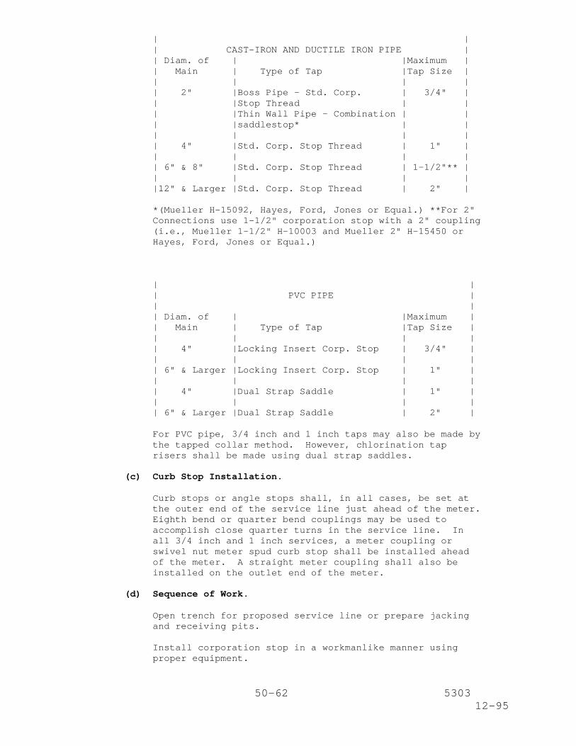
50-62 530312-95
| || CAST-IRON AND DUCTILE IRON PIPE || Diam. of | |Maximum || Main | Type of Tap |Tap Size || | | || 2" |Boss Pipe - Std. Corp. | 3/4" || |Stop Thread | || |Thin Wall Pipe - Combination | || |saddlestop* | || | | || 4" |Std. Corp. Stop Thread | 1" || | | || 6" & 8" |Std. Corp. Stop Thread | 1-1/2"** || | | ||12" & Larger |Std. Corp. Stop Thread | 2" |
*(Mueller H-15092, Hayes, Ford, Jones or Equal.) **For 2"Connections use 1-1/2" corporation stop with a 2" coupling(i.e., Mueller 1-1/2" H-10003 and Mueller 2" H-15450 orHayes, Ford, Jones or Equal.)
| || PVC PIPE || || Diam. of | |Maximum || Main | Type of Tap |Tap Size || | | || 4" |Locking Insert Corp. Stop | 3/4" || | | || 6" & Larger |Locking Insert Corp. Stop | 1" || | | || 4" |Dual Strap Saddle | 1" || | | || 6" & Larger |Dual Strap Saddle | 2" |
For PVC pipe, 3/4 inch and 1 inch taps may also be made bythe tapped collar method. However, chlorination taprisers shall be made using dual strap saddles.
(c) Curb Stop Installation.
Curb stops or angle stops shall, in all cases, be set atthe outer end of the service line just ahead of the meter.Eighth bend or quarter bend couplings may be used toaccomplish close quarter turns in the service line. Inall 3/4 inch and 1 inch services, a meter coupling orswivel nut meter spud curb stop shall be installed aheadof the meter. A straight meter coupling shall also beinstalled on the outlet end of the meter.
(d) Sequence of Work.
Open trench for proposed service line or prepare jackingand receiving pits.
Install corporation stop in a workmanlike manner usingproper equipment.
51-62 530312-95
Install copper service line and connect to corporationstop.
Install curb stop on the meter end of the service line.
With curb stop open, and prior to connecting service lineto meter, open corporation stop and flush service lineadequately. Close curb stop, leaving corporation stop infull open position.
Check service line for apparent leaks.
Connect service line to meter and if necessary adjustmeter location. Care shall be taken to make sure that theinlet side of meter is connected to city service line.Momentarily open curb stop to verify proper registrationof meter.
Backfill all excavations; tamp the backfill material inplace to the density of the soil in the adjacent trenchwalls.
If the meter is to be relocated, the meter box shall bereplaced so that it is centered over the meter with top oflid flush with finished grade. When the meter must belocated in driveways or sidewalks, the Contractor will berequired to furnish and install an approved traffic typemeter box with cast-iron lid.
(21) Abandonment of Water Mains.
Where plans call for the abandonment of mains, the followinggeneral procedure shall be followed:
After the replacement main has been constructed,sterilized, tested and released, and all services trans-ferred to the replacement main, the main to be abandonedshall be located and traced back to the feeder main and atthis point cut and plugged. Normally, this is done byinstalling a plug, clamp and a concrete reaction block.In cases of 1-1/2 inch or 2 inch Corporation Cock or TS &V connections, the valve shall be closed and a cap or pluginstalled. In no instances shall the line to beabandoned be valved off at the nearest valve or cut andplugged other than at the supply main.
All ends or openings in abandoned mains shall be ade-quately plugged or capped in an approved manner and allexcavations backfilled to the Engineer's satisfaction andany street surfaces replaced.
All surface identification shall be removed, i.e., valveboxes and fire hydrants. Valve boxes, when in improvedstreets other than shell, may be poured full of concretewith the cap permanently removed.
(22) Service Lines of Public Utilities.
Where any pipe or conduit of a public utility corporationcrosses the water main trench, such pipe or conduit shall besupported in a manner satisfactory to the Engineer.
52-62 530312-95
Should the Contractor consider it necessary for a utilitycorporation to relocate utility lines or other improvements,the Contractor must notify the Engineer in advance. TheEngineer will make the necessary arrangements with the utilitycorporation if he considers it imperative that the change bemade. The State will not be liable for damages on account ofdelays due to changes made by the utility corporations whichhinder the progress of work of the water main Contractor.
(23) Water Meter and Meter Vault.
(a) Salvaging of Existing Valves, etc.
Existing valves, piping and appurtenances inside vaultshall be salvaged and returned to the utility ownerdesignated on the plans.
(b) Installation of Pipe, Tapping Sleeves, Valves, ServiceLines and Other Appurtenances.
Pipe, tapping sleeves, valves, service lines and otherappurtenances shall be installed in accordance with thepertinent items of this specification or as directed bythe Engineer.
(c) Vault Construction.
(i) Precast Concrete Vault.
The precast concrete vault shall be set level on abed of sand in an excavation and brought to grade.Piping shall then be installed and sand shall bebackfilled around vault.
(ii) Cast-in-Place Concrete Vault.
The cast-in-place concrete vault shall beconstructed as shown on the plans.
(iii) Solid Masonry Wall Vault.
The solid masonry wall vault shall be constructedas shown on the plans.
(iv) Frame and Cover.
Frame and cover shall be constructed as shown onthe plans.
In grass areas, the frame and cover shall be set 2inches to 3 inches above natural ground or finishedgrade and parallel to it (maximum angle fromhorizontal shall be 20 degrees). Backfill shall besloped away from meter.
In sidewalk areas, the frame and cover shall be set1/2 inch to 1 inch above adjacent concrete andparallel to it. Replacement concrete shall besloped away from meter.
53-62 530312-95
All covers shall have one coat of metal primer andone coat of black industrial rust proof paint. Allother meter vault surfaces except portion of frameagainst concrete shall have a thick coat ofasphaltic paint.
(d) Inspections.
The following inspections shall be made jointly by theEngineer and representatives of the utility owner:
(1) Site Location Inspection - proposed meter locationmust be approved prior to commencing work.
(2) Final Inspection - to be conducted after all back-fill is in place, cover installed, cleanup completed,and surface is restored.
(e) Adjusting Meter Vaults.
Meter vaults shall be adjusted as shown on the plans or asdirected by the Engineer.
(24) Removing and Relocating Fire Hydrants, Valves and Boxes.
Valves and boxes which are to be removed and relocated shall bethoroughly cleaned before installation at the locations shownon the plans. They shall be installed in accordance with therequirements of Subarticle 3.(11) of these specifications.Should the Contractor damage or fail to properly reclaim suchvalves and boxes, he will be required to replace them in kindat his entire expense.
At his option, the Contractor may substitute a new valve andbox. All substituted items shall conform to the applicablerequirements of this specification, but no additional paymentwill be made for furnishing such substitutions. Should thisoption be chosen, the existing valve and box shall become theproperty of the Contractor.
(25) Installation of Split Casing.
The Contractor shall notify the utility owner, not less than 48hours in advance, of any work planned involving existing waterlines. Water lines to be encased shall not have more than 20feet exposed at any time.
6 inch x 6 inch x 1-1/4 inch neoprene pads shall be placedbetween the split casing sections and the top and bottom of thewater lines at approximately six (6) foot spacings or asdirected by the Engineer.
The trench when completed and shaped to receive the casingshall be of sufficient width to provide free working space forsatisfactorily installing the casing and backfilling under andaround the casing.
The split casing shall be held in place for welding by hinges,coupling bands or any other method acceptable to the Engineer.
All welded joints shall conform to the requirements of AWWA
54-62 530312-95
Standard C 206. Welds shall be such as to develop the fullstrength of the pipe throughout the joint.
The ends of the encasement pipe shall be plugged with a claycore to prevent entrance of excessive ground water.
(26) Securing, Supporting, and Anchoring.
(a) Pipe Supports.
Piping shall be supported as shown on the drawings and asspecified herein to maintain line and grade and preventthe transfer of stress to adjacent structures.
(b) Anchorage of Main Line Fittings.
Thrust reaction due to fittings and bends shall berestrained through the pipe wall and joint welds. Whereshown on the plans, prestressed concrete cylinder pipefittings and bends installed on the water main shall beanchored by welding consecutive joints of pipe together toa distance on each side of the fitting. Steel Cylinderthickness shall be sufficient for the transfer of theseforces longitudinally along the pipeline. The length ofthe restrained joints assumes that hydrostatic testingwill begin upstream and proceed downstream with respect tothe normal flow of the water in the pipe. If installationor testing of the pipe differs from this assumption, theContractor shall submit for approval a revised method ofrestraining the pipe joints upstream and/or downstream ofthe device used to test against (i.e., block valve, blindflange, or dished head plug).
(c) Temporary Anchorage of Fittings.
The Contractor is responsible for providing adequatetemporary blocking around fittings when making connectionsto the distribution system and during hydrostatic tests.
(27) Modifications for Cathodic Protection.
(a) General.
Cathodic protection systems shall be in accordance withSpecial Specification Item, "Cathodic Protection Systemsfor Large Diameter Water Main", as specified herein, andthe contract drawings.
References to steel pipe shall be interpreted to apply totape-coated welded steel pipe.
Prestressed Concrete Cylinder pipe shall be modified forcathodic protection as required to ensure that allmetallic components, including the wire wrap are tiedtogether. The wire shall be attached to the cylinder ateach end of the joint by welding in accordance withparagraph 5.5.2 of AWWA C205.
55-62 530312-95
(b) Bonded Joints.
Where rubber gasket bell and spigots are provided, thecontractor shall provide for bonded joints by eitherwelding a strap or clip between the bell and the spigot ofeach joint or by providing a thermite welded cable betweenthe bell and the spigot of each joint. All pipe, whetherinstalled in a tunnel or open cut, shall have bondedjoints, except where insulating flanges are to beprovided. Where joints are welded for thrust restraint,no additional bonding will be required.
(c) Bonding Strap or Clip.
The strap or clip for bonding the bell to the spigot shallbe free of all foreign material that may increase thecontact resistance between wire and strap or clip.
Unless otherwise noted, insulation kits shall be providedat connections to the existing water system or atlocations to isolate one type of cathodic system fromanother type, between the water main, access manholepiping and other major openings in the water main, or asshown on the drawings.
(28) Auger Construction - Auger Holes and Auger Pits.
The minimum width of auger pits shall be such that there shallbe at least six (6) inches of space between the pipe and thewalls of the auger pit. The maximum allowable width of the pitshall be five (5) feet unless approved by the Engineer. Thewidth of the pit at the surface shall not be less than at thebottom. The maximum allowable length of the pit shall be notmore than five (5) feet longer than one (1) full joint of pipeof the type being used and shall not exceed 25 feet unlessapproved by the Engineer.
All auger pits shall be excavated to a finished grade at leastsix (6) inches lower than that indicated by the stakes or asapproved by the Engineer to ensure that a dry bottom isencountered.
Locations of auger pits shall be determined by the Contractorsuch that there is minimum interference with traffic. TheContractor shall submit a location plan of auger pits and alllocations of auger pits shall be approved prior to constructionby the Engineer. The as-built drawings shall show all actualauger pit locations dimensioned in a manner that they can beidentified in the field. The typical distance between centerlines of consecutive auger pits shall not be less than 80 feet,unless approved by the Engineer.
All excess excavated material shall be removed from the site asrequired and be disposed of by the Contractor at the time ofexcavation.
The auger hole shall be augered mechanically with a suitableaugering assembly designed to produce a smooth, straight shaftand so operated that the completed shaft shall be at theestablished line and grade. The size of the augered hole shallbe of such diameter to provide ample clearance for bells or
56-62 530312-95
other joints, but no more than two (2) inches larger than thediameter of the bell on the pipe. The augering shall be doneusing a pilot hole. By this method an approximate 2-inch pilothole shall be bored the entire length to be augered and shallbe checked for line and grade on the opposite end of the borefrom the auger pit. The pilot hole shall serve as the centerline of the larger diameter hole to be augered. After the holehas been augered, a cleanout plug must be pulled through theaugered hole before the pipe is installed.
(29) Removing and Salvaging Fire Hydrants.
Fire Hydrants to be removed and salvaged shall be delivered totheir owner at the location set forth on the plans or asdirected by the Engineer.
(30) Installation of the Nonmetallic Pipe Detection System.
The nonmetallic pipe detection system shall be installedconcurrently with the proposed pipe placement. Thisinstallation shall be as specified by the manufacturer and/oras approved by the Engineer.
4. Measurement.
Measurement of completed and accepted work as described herein shallbe as follows:
"Pipe Water Main (Cast-Iron)", "Pipe Water Main (Steel) "PipeWater Main (Ductile-Iron)", "Pipe Water Main (Asbestos-Cement)", "Pipe Water Main (Copper)", "Pipe Water Main(Polyvinyl Chloride)", "Pipe Water Main (Prestressed ConcreteCylinder Pipe)" and "Casing (Steel)", of the various sizesshown on the plans, will be measured by the linear foot. Thewater mains and/or casing will be measured along the axis ofthe pipe and no deductions will be made for valves or fittings.Reducers shall be classed as pipe of the size of the largerend.
"Jacking, Boring or Tunneling (Water Main)" and "Jacking,Boring or Tunneling Casing (Steel)" will be measured by thelinear foot of the size and type of water main or casingjacked, bored or tunneled.
New copper service lines of the various sizes will be measuredas each "Service Line (Short Side)" or "Service Line (LongSide)". "Service Line (Short Side)" shall refer to serviceconnections to be made to meters on the same side of the streeton which the supply main is located. "Service Line (LongSide)" shall refer to service connections to be made to meterson the opposite side of the street on which the supply main islocated, or from the center of the street where the supply mainis located in the center of the street.
"Gate Valve and Box (Cast-Iron)" will be measured as each suchassembly of the various sizes installed.
"Tapping Sleeve, Valve and Box" will be measured as each suchassembly of the various sizes installed.
"Butterfly Valve and Box" will be measured as each such
57-62 530312-95
assembly of the various sizes installed.
"Fire Hydrant" and "Fire Hydrant with Valve and Box (of thesize of valve specified) will be measured as each such assemblyinstalled. Each fire hydrant shall be equipped with sufficientbarrel length to provide a minimum of four (4) feet from thebottom of the inlet line (connecting pipe) to the ground line.
"Additional Barrel Length" will be measured by the linear footof additional barrel length (over and above the length providedfor under the Item, "Fire Hydrant") required to install theupper barrel at the elevation shown on the plans or at theelevation directed by the Engineer.
"Removing and Relocating Meter, Meter Box and Curb Stop" willbe measured as each such assembly removed, cleaned andinstalled in the new location.
"Adjusting Valve Boxes" will be measured as each such assemblyadjusted to the corresponding finished grade.
"Lowering Water Mains" will be measured by the linear foot ofthe size and type of pipe lowered.
"Excavation (Water Main)", "Sand Backfill (Water Main)" and"Cement Stabilized Backfill (Water Main)" will be measured bythe cubic yard. Determination of plan quantities for"Excavation (Water Main)", "Sand Backfill (water Main)" and"Cement Stabilized Backfill (Water Main)" will be made by themethod of average end areas and will be based on the excavationand backfill diagrams shown on the plans. Quantities for"Excavation (Water Main)", "Sand Backfill (Water Main)" and"Cement Stabilized Backfill (Water Main)" as shown on the plansand in the proposal shall be considered as final quantities andno further measurement will be made unless changes in alignmentor grade are ordered by the Engineer. However, if evidence isfurnished by the Contractor, or if it is determined by theEngineer that substantial variations exist between thequantities shown on the plans and the actual quantities, thesubject quantities will be recalculated.
"Removing and Relocating Valve and Box" will be measured aseach such assembly removed, cleaned and installed in thelocation shown on the plans.
"Water Meter and Meter Vault" will be measured as each suchassembly constructed complete in place at the location shown onthe plans.
"Adjusting Meter Vaults" will be measured as each meter vaultadjusted.
"Removing Fire Hydrants" and "Removing Fire Hydrant with Valveand Box Assembly" will be measured as each removed and disposedof as noted on the plans.
"Removing Water Mains", of the various sizes shown on theplans, will be measured by the linear foot of water mainremoved and disposed of as noted on the plans.
"Air Release and Vacuum Relief Valves" will be measured as each
58-62 530312-95
such assembly, of the various sizes installed.
"Steel Casing" of the various sizes shown on the plans, will bemeasured by the linear foot complete in place.
"Remove and Salvage Water Valve and Boxes" will be measured aseach such assembly as designated on the plans.
"Fire Hydrant Branch Length" will be measured by the linearfoot of the pipe length of the various sizes and types shown onthe plans. Fire hydrant branches will be measured from theaxis of the main to the centerline of the hydrant. Reducerswill not be paid for directly."Removing and Salvaging Gate Valve and Box" will be measured aseach such assembly as designated on the plans.
"Abandonment of Water Mains" will be measured by each unit ofthe size pipe abandoned.
"Pressure Reducing Stations" will be measured as a contractlump-sum unit constructed complete in place at the locationsshown on the plans.
"Salvaging and Relocating Water Meter and Box" will be measuredas each such assembly salvaged, cleaned and installed at thenew location.
"Removing and Relocating Fire Hydrants, Valve and Box" will bemeasured as each such assembly removed, salvaged, cleaned andrelocated at the new location.
"Removing and Salvaging Fire Hydrant" and "Removing andSalvaging Fire Hydrant, Valve and Box" will be measured by eachsuch assembly removed, salvaged, cleaned and delivered to theirowner as shown on the plans.
"Blow Off Valve" will be measured as each such assembly, of thevarious sizes installed.
"Augering (Water Main)" and "Augering (Casing)", will bemeasured by the linear foot of the size and type of water mainor casing augered.
"Cut and Plug Water Main" will be measured by each unit of thesize pipe indicated.
"Adjusting Manholes (Water Main)" will be measured by eachunit. The excavation and backfill required will not bemeasured for payment but will be considered subsidiary to thevarious bid items.
"Manholes (Water Main)" will be measured as each such unit asindicated on the plans. Rings and covers will not be measuredfor payment but shall be considered subsidiary to the Item,"Manholes (Water Main)".
5. Payment.
The work performed and materials furnished in accordance with thisspecification and measured as provided under "Measurement" will bepaid for at the unit prices bid for the items of work hereinafter
59-62 530312-95
described. These prices shall be full compensation for furnishingand hauling all materials; for placing or installing the materials;for inspection and testing; and for all other items of material,labor, equipment, tools and incidentals necessary to complete thework in accordance with the plans and specifications.
Payment for "Pipe Water Main (Cast-Iron)", "Pipe Water Main(Steel)", "Pipe Water Main (Ductile-Iron)", "Pipe Water Main(Asbestos Cement)", "Pipe Water Main (Copper)", "Pipe Water Main(Polyvinyl Chloride", "Pipe Water Main (Prestressed ConcreteCylinder Pipe)" and "Casing (Steel)" will be made at the unit pricebid per linear foot of pipe of the various sizes installed by theopen cut method.
Payment for "Jacking, Boring or Tunneling (Water Main)" will be madeat the unit price bid per linear foot of the size and type of watermain jacked, bored or tunneled, which price shall include furnishingthe pipe.
Payment for "Jacking, Boring or Tunneling Casing (Steel)" will bemade at the unit price bid per linear foot of the casing jacked,bored or tunneled, which price shall include the casing. Water mainplaced in the casing will be paid for at the unit price bid perlinear foot of "Pipe Water Main" of the size and type specified.
Payment for "Service Line (Short Side)" and "Service Line (LongSide)", of the size specified, will be made at the unit price bidfor each service line installed, which price shall be fullcompensation for all labor, materials, excavation and backfillrequired to install the facility complete in place, includingconnection to the customer's service line.
Payment for "Gate Valve and Box (Cast-Iron)", "Tapping Sleeve, Valveand Box", and "Butterfly Valve and Box" will be made at the unitprice bid for each such assembly of the various sizes installed.
Payment for "Fire Hydrant" and "Fire Hydrant with Valve and Box" (ofthe size of valve specified) will be made at the unit price bid foreach such assembly installed. Payment for "Additional BarrelLength" will be made at the unit price bid per linear foot ofadditional fire hydrant barrel as defined under "Measurement".
Payment for "Removing and Relocating Meter, Meter Box and Curb Stop"will be made at the unit price bid for each such assembly removed,cleaned and installed in the new location.
Payment for "Adjusting Valve Boxes" will be made at the unit pricebid for each valve box adjusted to finish grade.
Payment for "Lowering Water Mains" of the type and size indicated onthe plans will be made at the unit price bid per linear foot of pipelowered. This price shall be full compensation for lowering andadjusting pipe, valves, boxes and service lines which are connectedthereto. Excavation and earth backfill required for lowering watermains will not be paid for directly but shall be consideredincidental to the various bid items.
Payment for water main excavation will be made at the unit price bidper cubic yard of "Excavation (Water Main)". This price shall befull compensation for the excavation and backfill for water mains;for the cutting and restoration of pavement and base courses; for
60-62 530312-95
hauling and disposition of surplus excavated material; and forsheathing, if required for support of walls of trenches less than 5feet in depth.
Excavation protection methods for excavations greater than five (5)feet in depth shall be measured and paid for as required under Item402, "Trench Excavation Protection", or Item 403, "Temporary SpecialShoring".
Payment for "Sand Backfill (Water Main)" will be made at the unitprice bid per cubic yard of "Sand Backfill (Water Main)".
Payment for "Cement Stabilized Backfill (Water Main)" measured aspreviously prescribed, will be made at the unit bid price for"Cement Stabilized Backfill (Water Main)".
Fittings, including necessary concrete blocking, pipe clamps,nipples, etc., will not be paid for directly but shall be con-sidered incidental to the water mains in which they are installed.If additional fittings are required due to plan changes or altera-tions in line and grade, they will not be paid for directly butshall be considered incidental to the water mains in which they areinstalled.
No direct payment will be made for furnishing and installing taps,risers, jumpers, blind flanges, cast-iron sleeves, plugs, etc., asrequired to sterilize and pressure test the new mains. This workshall be considered incidental to the various pay items. In addi-tion, the Contractor shall perform, without extra compensation, allnecessary excavation and maintenance of excavations until completionof pressure testing, sterilization and backfilling.
Wet connections will not be paid for directly but shall be con-sidered incidental to the various pay items.
Unless otherwise specified on the plans, the work performed andmaterials furnished to support pipes or conduits of public utilitieswill not be paid for directly but shall be considered incidental tothe various pay items.
Payment for "Removing and Relocating Valve and Box" will be made atthe unit price bid for each such assembly removed, cleaned andinstalled in the new location.
Payment for "Water Meter and Meter Vault" will be made at the unitprice bid for each such assembly installed. This price shall befull compensation for performing the necessary excavation andbackfill, constructing the concrete vault, and installation ofpiping, fittings, valves, adapters, strainers and meters.
Payment for "Adjusting Meter Vaults" will be made at the unit pricebid for each meter vault adjusted. This price shall be fullcompensation for furnishing all required materials, includingbackfill as required, excavation, tools, labor, equipment andincidentals required to complete the work.
Payment for "Removing Fire Hydrants" and "Removing Fire Hydrant withValve and Box Assembly" will be made at the unit price bid for eachsuch assembly, removed from the existing location and disposed of asnoted on the plans. Excavation and backfill required for removingfire hydrants will not be paid for directly but shall be considered
61-62 530312-95
subsidiary to the various bid items.
Payment for "Removing Water Mains" will be made at the unit pricebid per linear foot, of the various sizes shown on the plans, ofexisting water mains to be removed. This price shall be fullcompensation for the removal and disposal of all pipe andappurtenances thereto, as directed by the Engineer. Excavation andbackfill required for removing water mains will not be paid fordirectly but shall be considered subsidiary to the various biditems.
Payment for "Air Release and Vacuum Relief Valves" will be made atthe unit price bid for each such assembly of the various sizesinstalled.
Payment for "Steel Casing" will be made at the unit price bid perlinear foot of casing of the various sizes installed by the open cutmethod.
Payment for "Remove and Salvage Water Valve and Boxes" will be madeat the unit price bid for each such assembly to be removed. Thisprice shall be full compensation for performing all excavation andbackfill required to remove water valve and boxes as set forthherein and including the removal and delivery to their owner ofwater valve and boxes and appurtenances thereto, as directed by theEngineer.
Payment for "Fire Hydrant Branch Length" will be made at the unitprice bid per linear foot of pipe length, of the various sizes andtypes shown on the plans. Reducers will not be paid for directlybut will be considered subsidiary to the various bid items.
Payment for "Removing and Salvaging Gate Valve and Box" will be madeat the unit price bid for each assembly removed from the existinglocation and delivered to its owner at the location shown on theplans or as directed by the Engineer. Excavation and backfillrequired for removing the Gate Valve and Box will not be paid fordirectly but shall be considered subsidiary to the various biditems.
Payment for "Abandonment of Water Mains" will be made at the unitprice bid for each unit of the size pipe to be abandoned. Thisprice shall be full compensation for performing all excavation,backfill, cutting and plugging of pipe and any other incidentalitems required to abandon the water main as set forth herein.
Payment for "Pressure Reducing Stations" will be made at thecontract lump-sum price bid as installed. This price shall be fullcompensation for performing the necessary excavation and backfill,constructing the concrete structure, furnishing and installing allstation appurtenances addressed under "Materials" of this provisionand removal of the existing station and piping.
Payment for "Salvaging and Relocating Water Meter and Box" will bemade at the unit price bid for each such assembly.
Payment for "Removing and Relocating Fire Hydrants Valve and Box"will be made at the unit price bid for each such assembly, removedfrom the existing location, salvaged, cleaned and relocated at thelocation shown on the plans. Excavation and backfill required forremoving and relocating fire hydrants, valve and box will not be
62-62 530312-95
paid for directly but shall be considered subsidiary to the variousbid items.
Payment for "Removing and Salvaging Fire Hydrant and Removing andSalvaging Fire Hydrant, Valve and Box" will be made at the unitprice bid for each assembly removed from the existing locationsalvaged, cleaned and delivered to their owner at the location setforth in the plans or as directed by the Engineer. Excavation andbackfill required for removing fire hydrants, valve and box will notbe paid for directly but shall be considered subsidiary to thevarious bid items.
Payment for "Blow Off Valve" will be made at the unit price bid foreach such assembly of the various sizes and types installed.
Payment for "Augering (Water Main)" or "Augering (Casing)" will bemade at the unit price bid per linear foot of the water main orcasing augered. This price shall include the water main pipe or thecasing pipe. Water main placed in the casing will be paid for atthe unit price bid per linear foot of "Pipe Water Main" of the sizeand type specified. Payment for "Augering (Water Main)" or"Augering (Casing)" shall include the construction of the augerpits, including excavation, backfill, disposal of excess excavatedmaterial, and all tools, equipment and labor necessary to performthe work.
Payment for "Cut and Plug Water Main" will be made at the unit pricebid for each unit of the size indicated.
Payment for "Adjusting Manholes (Water Main)" will be made at theunit price bid for each unit.
Payment for "Manholes (Water Main)" will be made at the unit pricebid for each unit as indicated on the plans.
No direct payment will be made for furnishing and installing thenonmetallic pipe detection system. This work and materials shall beconsidered incidental to the various pay items. In addition, theContractor shall ensure that the detection system is complete andoperational to the satisfaction of the owner of the utility line.