Embed Size (px)
Citation preview

Proceedings of the 1996 Winter Simulation Conferenceed. J. M. Cbarnes, D. J. Morrice, D. T. Brunner, and J. J. Slvain
DEVELOPING A REAL-TIME EMULATION/SIMULATION CAPABILITY FOR THECONTROL ARCHITECTURE TO THE RAl\1P FMS
Wayne J. DavisJoseph G. MacroAndrew L. Brook
Michael S. LeeGuoyan S. Zhou
Department of General EngineeringUniversity of Illinois at Urbana-Champaign
Urbana, IL 61801 U.S.A
ABSTRACT
This paper fITst discusses an object-oriented, control architecture and then applies the architecture to produce areal-time software emulator for the Rapid Acquisition ofManufactured Parts (RAMP) flexible manufacturing system (FMS). In specifying the control architecture, the coordinated object is frrst defined as the primary modelingelement. These coordinated objects are then integrated intoa Recursive, Object-Oriented Coordination Hierarchy. Anew simulation methodology, the Hierarchical Object-Oriented Programmable Logic Simulator, is then employedto model the interactions among the coordinated objects.The final step in implementing the emulator is to distribute the models of the coordinated objects over a networkof computers and to synchronize their operation to a realtime clock. Specialized displays have also been developed to allow one to monitor the detailed, real-time operation of each coordinated object. The research will alsoconvert the real-time emulation 'model into a real-timesimulation model for the RAMP FMS. Both the real-timeemulation and simulation capabilities will be demonstratedat the presentation.
1. INTRODUCTION
Although simulation remains the tool of choice for modeling the behavior of FMSs, the accuracy of current simulation tools in modeling modem manufacturing systems suchas Aexible Manufacturing Systems (FMSs) has been questioned. Mize et al. [1991] have concluded that currentsimulation tools cannot accurately estimate the true performance of an FMS. Rather, these merely permit the modelerto compare the relative performance differences amongalternative designs for the RvtS.
In our research, we have consistently observed thatavailable simulation tools overestimate the performance
171
for an operational FNlS (see Flanders and Davis [1995] fora real-world example). We believe that the inherent inaccuracy of current simulation tools arises from the inabilityto model all the constraints associated with the operation ofan FMS. Current simulation tools focus on modeling theprimary job entity as it flows through a stochastic queueingnetwork representation of the FMS. Few, ifany, simulationtools readily permit the modeler to consider the flow of thesupporting resources (e.g. tooling, part kits, fixtures, andprocessing plans). The coordination ofall entity flows in anFMS is crucial, and it is the interactions among the controllers within the AvIS that coordinate these flows (see Davisetal. [1993]).
A new simulation methodology has been developedto explicitly model the controller interactions. This methodology also permits the immediate consideration of thedetailed processing plans for the parts to be produced in theRvtS. In this manner, all entity flows are considered. Thispaper discusses an application of this simulation methodology to construct a software emulator for the control architecture of a RAMP FMS that is operated by the Naval AirWarfare Center/Aircraft Divisioniindianapolis (NAWC ADIndpls). This FNlS will produce new and spare electroniccircuit boards for defense systems using through-the-holeassembly technologies. The complexity of this system isevidenced by the fact that the cell controller requires nearlya million lines of computer code to implement, excludingthe numerous off-the-shelf software packages containedwithin the controller. Given this complexity, no priorattempt to simulate the entire system has been successful,and production capabilities are still unconfrrmed. Furthermore, given the current failure to model the dynamics forthis FMS, the ability to schedule this FMS has been compromised. The development of the emulator is the fIrst steptoward the development ofa new scheduler for this system.This scheduler will be developed within the framework ofa comprehensive methodology for the modeling, scheduling and control ofFNlSs JS discussed in Davis et al. [1993].
172 Davis et al.
In this State-of-the-Art tutorial, a detailed discussion of the development of the real-time emulator for theRAMP FMS will be provided. The conversion of the realtime emulator into a real-time simulator for the RAMPFMS will also be addressed. Finally, an on-line demonstration of the real-time emulation and simulation capabilitywill be provided.
2. MODELING APPROACH
2.1 The Coordinated Object
In order to define the set of subsystems containedwithin a FMS, we sought to find a single modeling template which could be recursively applied to decompose thesystem into its component subsystems. Working in collaboration with the Government Systems Group atMotorola, we first published the fractal architecture as amechanism for decomposing the factory into its constituent processing elements (see Tirpak et al. [1992]). Duringthe past few years, the basic fractal unit defined in thatarchitecture has been generalized to become the coordinated object, and we now refer to the fractal architectureas the Recursive Object-Oriented Coordination Hierarchy.
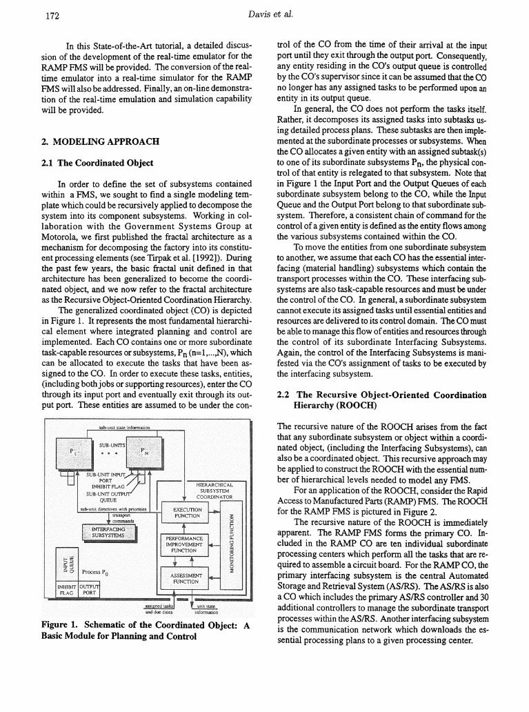
The generalized coordinated object (CO) is depictedin Figure 1. It represents the most fundamental hierarchical element where integrated planning and control areimplemented. Each CO contains one or more subordinatetask-capable resources or subsysterns, Pn (n=1,... ,N), whichcan be allocated to execute the tasks that have been assigned to the CO. In order to execute these tasks, entities,(including bothjobs or supporting resources), enter the COthrough its input port and eventually exit through its output port. These entities are assumed to be under the con-
Figure 1. Schematic of the Coordinated Object: ABasic Module for Planning and Control
trol of the CO from the time of their arrival at the inputport until they exit through the output port. Consequently,any entity residing in the CO's output queue is controlledby the CO's supervisor since it can be assumed that the COno longer has any assigned tasks to be performed upon anentity in its output queue.
In general, the CO does not perfoffil the tasks itself.Rather, it decomposes its assigned tasks into subtasks using detailed process plans. These subtasks are then implemented at the subordinate processes or subsystems. Whenthe CO allocates a given entity with an assigned subtask(s)to one of its subordinate subsystems Pn, the physical control of that entity is relegated to that subsystem. Note thatin Figure 1 the Input Port and the Output Queues of eachsubordinate subsystem belong to the CO, while the InputQueue and the Output Port belong to that subordinate subsystem. Therefore, a consistent chain of command for thecontrol of a given entity is defined as the entity flows amongthe various subsystems contained within the CO.
To move the entities from one subordinate subsystemto another, we assume that each CO has the essential interfacing (material handling) subsystems which contain thetransport processes within the CO. These interfacing subsystems are also task-capable resources and must be underthe control of the CO. In general, a subordinate subsystemcannot execute its assigned tasks until essential entities andresources are delivered to its control domain. The CO mustbe able to manage this flow ofentities and resources throughthe control of its subordinate Interfacing Subsystems.Again, the control of the Interfacing Subsystems is manifested via the CO's assignment of tasks to be executed bythe interfacing subsystem.
2.2 The Recursive Object-Oriented CoordinationHierarchy (ROOCH)
The recursive nature of the ROaCH arises from the factthat any subordinate subsystem or object within a coordinated object, (including the Interfacing Subsystems), canalso be a coordinated object. This recursive approach maybe applied to construct the ROaCH with the essential number of hierarchical levels needed to model any FMS.
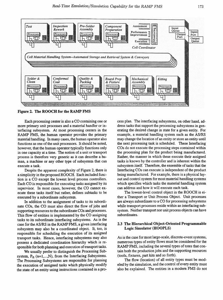
For an application of the ROaCH, consider the RapidAccess to Manufactured Parts (RAMP) FMS. The ROaCHfor the RAMP FMS is pictured in Figure 2.
The recursive nature of the ROOCH is immediatelyapparent. The RAMP FMS forms the primary CO. Included in the RAMP CO are ten individual subordinateprocessing centers which perfonn all the tasks that are required to assemble a circuit board. For the RAMP CO, theprimary interfacing subsystem is the central AutomatedStorage and Retrieval System (ASIRS). The ASIRS is alsoa CO which includes the primary ASIRS controller and 30additional controllers to manage the subordinate transportprocesses within the ASIRS. Another interfacing subsystemis the communication network which downloads the essential processing plans to a given processing center.
Real-Time Emulation/Simulation Capability for the RAMP FMS 173
Figure 2. The ROOCH for the RAMP FMS
Each processing center is also a CO containing one ormore primary unit processes and a material handler or interfacing subsystem. At most processing centers in theRAMP FMS, the human operator provides the primarymaterial handling. In many cases, the human operator alsofunctions as one of the unit processors. It should be noted,however, that the human operator typically functions onlyin one capacity at a time. The notion of a unit or transportprocess is therefore very generic as it can describe a human, a machine or any other type of subsystem that canexecute a task.
Despite the apparent complexity of Figure 2, there isa simplicity in the proposed ROaCH. Each included function is a CO except the lowest level process controllers.Each CO is responsible for executing tasks assigned by itssupervisor. In most cases, however, the CO cannot execute these tasks itself but rather, defines subtasks to beexecuted by a subordinate subsystem.
In addition to the assignment of tasks to its subordinate COs, the CO must also direct the flow of jobs andsupporting resources to the subordinate cas and processes.This flow of entities is implemented by the CO assigningtasks to its subordinate interfacing subsystems. As is thecase for the ASIRS in the RAMP FMS, a given interfacingsubsystem may also be a coordinated object. It, too, isresponsible for scheduling the execution of its assignedtransport tasks. Hence, interfacing subsystems may alsopossess a dedicated coordination hierarchy which is responsible for both planning and execution of transport tasks.
We usually prefer to distinguish the Processing Subsystem, Pn (n=l,... ,N), from the Interfacing Subsystems.The Processing Subsystems are responsible for planningthe execution of assigned tasks which physically modifythe state of an entity using instructions contained in a pro-
cess plan. The interfacing subsystems, on other hand, address tasks that support the processing subsystems in generating the desired change in state for a given entity. Forexample, a material handling system such as the ASIRSmay change the location of an entity or store an entity untilthe next processing task is scheduled. These InterfacingCOs do not execute the processing steps contained withinthe processing plan for the product being manufactured.Rather, the manner in which these execute their assignedtasks is known by the controller and is inherent within thesubsystem itself. Therefore, the ensemble of tasks that theInterfacing COs can execute is independent of the productbeing manufactured. For example, there is a physical layout and control system for most material handling systemswhich specifies which tasks the material handling systemcan address and how it will execute each task.
The lowest-level control object in the ROaCH is either a Transport or Unit Process Object. Unit processesare always subordinate to a CO for processing subsystemswhile transport processes reside within an interfacing subsystem. Neither transport nor unit process objects can havesubordinates.
2.3 The Hierarchical Object-Oriented ProgrammableLogic Simulator (HOOPLS)
As is the case for most large-scale, discrete-event systems,numerous types of entity flows must be considered for theRAMP FMS, including the several types of totes that contain both the production jobs and the supporting resources(tools, fixtures, part kits and so forth).
The flow (location) of all entity types must be modeled by the simulation, and the control of every entity mustalso be explained. The entities in a modern FMS do not
174 Davis et al.
flow of their own volition. Rather, their flows are managed by controllers. Furthermore, whenever there is aninteraction among the controllers, there is likely an exchange of control for one or more entities among the interacting controllers. A new simulation approach, the Hierarchical Object-Oriented Programmable Logic Simulator(HOOPLS), has been formulated to explicitly address thesecontroller interaction concerns.
A HOOPLS-based model for a FMS consists of fourprimary frames. The first frame is the model frame whichcontains the specifications for the ROOCH associated withthe modeled FMS. The second frame is the control framewhich provides for the exhaustive definition of the controlmessages that will be issued or received by each controller contained within the ROOCH. This frame also definesthe state transition mechanisms which occur upon the receipt of a control message and the subsequent controlmessage(s) that are issued.
Given that HOOPLS explicitly models the interactionamong the controllers within the ROOCH and considersthe flow of all entities to be a consequence of these interactions, HOOPLS has abandoned the use ofa traditionalevent calendar. Instead, HOOPLS employs a messagerelay which stores the control messages that will be passedamong the controllers, chronologically-ordered based upontheir delivery time. Each control message designates thecontroller that issued the message, the recipient controllerfor the message, the message content, and the scheduleddelivery time. The message relay is responsible for delivering the control message to the recipient controller at theappropriate simulated time. It is obvious that the prescribedoperation of the message relay physically mimics the communication network which links the controllers in an actual FMS (for the RAMP FMS, this is a dedicated LocalArea Network).
The third simulation frame in the HOOPLS-basedmodel is the processing plan frame. The processing plandetails not only which manufacturing processes will berequired, and in which order, but also details which supporting resources will be required to complete a processing task.
The fourth simulation frame is the experimentalframe which specifies the experimental parameters governing the simulation study. The experiment frame alsoincludes extensive capabilities for initializing the simulation to a known system state.
To demonstrate the modeling objectives for HOOPLS,a simulation/emulation model developed for the RAMPFMS will now be summarized. HOOPLS intrinsically employs an object-oriented architecture, and the C++ programming language was selected for implementing of the simulation model. In addition, the object-oriented design andanalysis methods detailed by Booch [1991] were used tospecify the class hierarchy for the objects.
3. IMPLEMENTING THE EMULATOR
3.1 Prior Modeling Effort
Space limitations do not pennit a detailed discussion ofall the essential steps that are required to construct theemulator. Rather, we can only provide an overview ofour basic approach. In an earlier paper, we discuss aninitial effort to construct the basic object classes for thecontrollers, entities, and control messages that are neededto describe the RAMP FMS (see Davis et al. [19~4]). TheROOCH used for this paper is depicted in Figure 2. Thissame ROOCH is also employed in the definition of themodel frame for the HOOPLS-based emulator.
The distinction between an emulation and simulationis simple. Both employ the same model. The primarydifference arises with the manner in which the model isexecuted. In a HOOPLS-based simulation approach, themessages are stored chronologically on a message calendar. After the state transitions arising from the receipt ofa given message at a given controller are implementedand the new controlled messages derived from the processing of the current message are chronologically storedin the message calendar, the next message is popped fromthe message calendar for processing. At this moment, thesimulation time is advanced to the delivery time for thenext control message to be popped. A HOOPLS-basedemulation uses the same approach save one fundamentaldifference. The emulation is also tied to a real-time clock.When the next message is removed from the event calendar, it will not be executed until the actual time at whichthat message is to be delivered to the recipient controller.Thus, the difference between an emulation and simulation may simply be summarized by saying that under asimulation, message processing procedures control theadvancement of time while under an emulation, the advancement of time is controlled by a real-time clock.
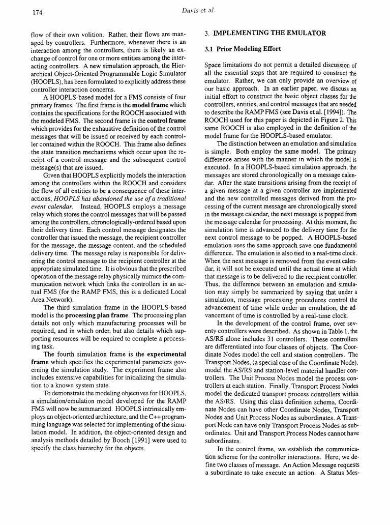
In the development of the control frame, over seventy controllers were described. As shown in Table 1, theAS/RS alone includes 31 controllers. These controllersare differentiated into four classes of objects. The Coordinate Nodes model the cell and station controllers. TheTransport Nodes, (a special case of the Coordinate Node),model the ASIRS and station-level material handler controllers. The Unit Process Nodes model the process controllers at each station. Finally, Transport Process Nodesmodel the dedicated transport process controllers withinthe ASIRS. Using this class definition schema, Coordinate Nodes can have other Coordinate Nodes, TransportNodes and Unit Process Nodes as subordinates. A Transport Node can have only Transport Process Nodes as subordinates. Unit and Transport Process Nodes cannot havesubordinates.
In the control frame, we establish the communication scheme for the controller interactions. Here, we define two classes of message. An Action Message requestsa subordinate to take execute an action. A Status Mes-
Real-Time Emulation/Simulation Capabili(v for the RAA1P FAJS 175
RAMP Cell ControllerKitting Station
Processor : Human OperatorMaterial Handler : Human Operator
Board Preparation StationProcessor : Human OperatorMaterial Handler: Human Operator
Component Preparation StationProcessor : Human OperatorMaterial Handler: Human OperatorPart CarouselTinning Robot
Pre-Solder Assembly StationProcessor : Human OperatorMaterial Handler: Human OperatorPart CarouselPart Location Indicator
Test Facility StationProcessor: Human OperatorMaterial Handler: Human OperatorBum In TesterConductivity Tester
InspectionlRework StationSimilar to Board Preparation Station
Mechanical Assembly StationSimilar to Board Preparation Station
Confonnal Coat StationSimilar to Board Preparation Station
Quality & Packaging StationSimilar to Board Preparation Station
Wave Solder and Clean StationSimilar to Board Preparation Station
Automated Storage and Retrieval SystemStorage layer Conveyors (6)InserterlExtractor (5)Machine Station Input/Output Conveyors (20)
Table 1. ControUers in the RAMP FMS
sage provides feedback to the supervisor at the completionof the requested action.
With the interaction of either a Coordinate Node orTransport Node with a subordinate of any class other thana Transport Node, we have three basic action messages.AcceptItem instructs the subordinate that an entity is in itsinput queue and that the subordinate now has control ofthat entity. ReturnItem instructs the subordinate to placethe entity in its output queue and return the control to therequesting supervisor. ExecuteTask requests the subordinate to execute a specific task upon a given item. If thesubordinate is a Coordinate Node or Unit Process Node,this task will be defined within the process plan database.If the subordinate is a Transport Node, then the instructionis predefined within the process's capabilities.
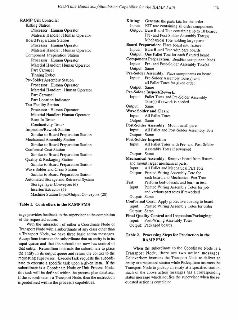
Kitting: Generate the parts kits for the orderInput: KIT tote containing all order componentsOutput: Bare Board Tote containing up to 10 boards
Pre- and Post-Solder Assembly Tote(s)Mechanical Tote holding large parts
Board Preparation: Place board into fixtureInput: Bare Board Tote with bare boardsOutput: One Pallet Tote for each fixtured board
Component Preparation: Bend/tin component leadsInput: Pre- and Post-Solder Assembly Tote(s)Output: Same
Pre-Solder Assembly: Place components on boardInput: Pre-Solder Assembly Tote(s) and
all Pallet Totes for given orderOutput: Same
Pre-Solder InspectlRework:Input: Pallet Totes and Pre-Solder Assembly
Tote(s) if rework is neededOutput: SameWave Solder and Clean:
Input: All Pallet TotesOutput: Same
Post-Solder Assembly: Mount small partsInput: All Pallet and Post-Solder Assembly ToteOutput: Same
Post-Solder InspectionInput: All Pallet Totes with Pre- and Post-Solder
Assembly Totes if reworkedOutput: Same
Mechanical Assembly: Remove board from fixtureand mount larger mechanical parts.Input: All Pallet and Mechanical Part ToteOutput: Printed Wiring Assembly Tote for
each board and Mechanical Part ToteTest: Perfonn bed-of-nails and burn-in test.
Input: Printed Wiring Assembly Totes for joband various part totes if reworked
Output: SameConformal Coat: Apply protective coating to board.
Input: Printed Wiring Assembly Totes for orderOutput: Same
Final Quality Control and InspectionIPackaging:Input: Post-Wiring Assembly TotesOutput: Packaged boards
Table 2. Processing Steps for Production in theRAMPFMS
When the subordinate to the Coordinate Node is aTransport N ode, there are two action messages.DelieverItem instructs the Transport Node to deliver anentity to a requested station while PickupItem instructs theTransport Node to pickup an entity at a specified station.Each of the above action messages has a correspondingstatus message which notifies the supervisor when the requested action is completed.

176 Davis et 81.
The process planning frame specifies the details forall the processing instructions needed to manufacture agiven part. A generic processing plan for any part manufactured in the RAMP FMS is given in Table 2. Note, however, that the actual process plan contains considerably moredetail pertaining to the execution of each task. For example, detailed instructions on how to bend the leads foreach component and where the component is to be placedupon the board are provided.
Finally, the experiment frame is very similar to that ofmost simulations detailing the length of the simulation runand other parameters that are needed to specify the simulation experimental trial. The experiment frame under theHOOPLS paradigm also provides extensive provision forinitializing the simulation to a known state.
3.2 On-Going Development of RAMP Emulator
The development of the emulator is initiated as a"clean-sheet" design. All that is being retained from theprior development of the HOOPLS-based simulation modelis the basic structure of the ROOCH and the control messages that will be employed. However, the list of controlmessages will probably be expanded. A distributed objectarchitecture is being employed in the development of theemulator such that each controller can be positioned on adifferent computer if desired. The controller objects arebeing coded in C++.
In developing the new emulation model, the greatesteffort has been devoted to the definition of the state variables for each coordinated object, especially the state variables for the ASIRS. There are several reasons for the focus upon the AS/RS. The AS/RS includes 30 transport processes. The complete ASIRS will have a total of 31 controllers, nearly half the total number of controllers in theentire RAMP FMS.
In defining the state variables for each control object,there are fundamental issues to be addressed. For example,should the AS/RS controller know the contents of the toteswhich contain jobs and supporting resources while theyare being stored and transported by the ASIRS? This singleissue has been the subject of hours of debate. Our currentdesign assumes that the ASIRS will know the contents ofthe totes. This decision extends the general capability ofthe formulation as the cell controller can request to the AS/RS that a given item be moved without specifying the totethat it is in. By making this design decision, the ASIRScan easily be replaced by another material handling system, one which may not employ totes. In fact, there arepresently other versions of the RAMP FMS which do notinclude an ASIRS.
Distributing the controllers across several computerscreates several other problems. First and foremost, amethod of communication between the objects on different computers must be developed. The computers, (in thiscase, Sun workstations), are networked. If a control objectwants to send a message to another control object across
this network, it needs to know on which computer the object resides. To fulfill the communication requirements,we have written our own mail system which knows theaddress of every control object. When an object desiresto send a message, it must specify the recipient of themessage, the time that the message is to be delivered, andthe contents of the message. The message is then placedinto the local computer's mail box. If the recipient objectresides on the same computer, the message-passing ishandled by the local mailer. If the recipient controller islocated at another computer, then the message is routed tothe mailer on the computer where the recipient object resides.
Messages are retained in the recipient object's mailbox until the scheduled time of their delivery. When themessages are delivered, the recipient controller executesthe appropriate state transitions and generates its responsemessages which it then places in its mail box for transmission to other controllers at the desired time.
Using the same message service, we have also included programmed features which will permit the emulation to proceed at a rate that is faster than real time.Specifically, we have included a clock object which monitors a real-time clock and advances the emulated time at atime-scale factor greater than real time. The clock objectsends messages to each computer's mail service specifying the current emulated time, which the mail service thenuses to detennine when messages are to be forwarded totheir recipient controllers.
Each controller type also has its own specialized display, which was developed under X-WindowslMotit®.Within each controller display, the state of the controlledsubsystem will be constantly updated. Much time has alsobeen devoted to the development of the displays. Ourdesire is for an individual to be able to view a given controller's window and visualize the operation of the subsystem that is being controlled. These displays also areespecially useful when validating the model. These provide a far more detailed depiction of the operation of thesystem than that which can be achieved using current simulation and animation techniques. Current animation capabilities provide iconic displays which permit only thebasic entity flow among the various objects to be depicted.Using our emulation capabilities, the modeler will be ableto access the detailed state information for each modeledobject within the simulation as it evolves in real-time. Theinteraction among the primary modeled controller objectscan also be visualized by monitoring the control messagesthat are being transmitted among the controllers.
3.3 The Demonstration
At the State-of-the-Art tutorial, we plan to demonstratethe real-time emulation of the RAMP FMS. The abilityto execute this demonstration is derived from anotherunique capability which we have included within the emulator. As stated above, we chose to employ a distributed-
Real-Time Emulation/Simulation Capabi1it.~· for the RAAiP FlvIS 177
object programming architecture within the emulationwhich permits each controller to be executed on a different platform. Each platform is connected to the Internet.To provide a future capability to model all types of RAMPFMSs, it was also necessary to implement the display window to each controller as a distinct programmed objectfrom the programmed object representing the controlleritself. Thus, a given controller and its associated controlwindow are separate programmed objects which can alsorun on different computers. This design decision also enhanced the virtual manufacturing capability by pennittingthe operations of the RAMP FMS to be viewed and eventually controlled from any computer on the Internet.
The computer code for the control displays is situatedat the computer where the displays are viewed. When thiscode is executed, the display object initially logs into themessage service for the emulation and provides the message service with its IF address on the Internet. Eventually, the message service will request the viewer's nameand password which it will then employ to control accessto certain state information and to limit the viewer's capability to interact with the operating RAMP FMS. Oncethe viewer has gained access, the primary control windowfor the RAMP FMS cell controller is opened at the remotelocation. The message service then notifies the cell controller for the RAMP FMS to begin sending state infonnation to the requesting window object at intervals of approximately I second duration.
The displaying software is contained at the distal location. Therefore, when the display object receives thestate information, it then employs the state informationbased upon the control window being viewed. It is important to observe that only textual state information is beingtransmitted across the Internet, not the entire pixel information that is needed to construct the control window.Therefore, the information transmission requirements areminimal.
The remote viewer can interact with the system asvarious elements of a given controller's window are userselectable icons. For example, when the viewer clicks theicon of the ASIRS within the cell controller window, theviewing programming immediately opens a window forthe ASIRS controller. The program then identifies themessage service that the viewer wishes to monitor the operations of the ASIRS. The message service then tells thecell controller to temporarily suspend state updates to theremote viewer and simultaneously tells the ASIRS controller to start sending state information updates..Withinthe ASIRS controller window, the viewer may choose tohave detailed infonnation presented for a given insertor/extractor or level of the storage conveyors.
As stated above, a simulation and an emulation differonly in the manner in which they advance time. When theemulation of the RAMP FMS is complete, the emulationmodel will immediately be converted to a simulation modelfor the RAMP FMS. Multiple instances of the resultingRAMP FMS simulation model will then be assigned to
distinct processors. Each instance of a simulation model(referred to as a simulation engine) will operate under adifferent control strategy and each simulation engine willreceive current state infonnation updates from the controlobjects executing the real-time emulation. Operating under the selected control strategy, each simulation will perfonn a real-time simulation of the future response of thesystem over a future planning horizon given the currentstate of the emulated system. Each simulation engine willattempt to generate real-time simulation trials as quicklyas possible.
Using the included message service, the output of thesereal-time simulation trials will be forwarded to the variousprogrammed objects which perfonn the essential real-timestatistical and compromise analyses which are needed toselect the best control strategy among the considered strategies for implementation. This capability will be demonstrated at the tutorial.
Given space limitations, we cannot discuss all the components of the real-time simulation analysis in this paper.Our basic approach to real-time simulation has been previously discussed in Davis, Wang and Hsieh [1991] andTirpak, Deligiannis and Davis [1992]. In a chapter of theforthcoming Handbook on Simulation (see Davis [1997]),we discuss evolving directions in simulation tools and realtime simulation. This chapter will provide an overview ofthe real-time simulation and emulation technology whichwill be demonstrated at the State-of-the-Art tutorial.Harmonosky [1995] also provides an abridged summaryof ongoing research in real-time simulation and scheduling.
5. FUTURE WORK
The emulator will be completed in time for this paperto be presented. After the emulator is completed, the emulation code will be modified such that it can operate as asecond generation, HOOPLS-based simulation model forthe RAMP FMS. This simulation model then will be employed to perfonn real-time simulation (see Davis, Wangand Hsieh [1991]). This is a necessary first step to develop a real-time production scheduler for the RAMP FMS(see Davis [1992] and Davis et ale [1993].
REFERENCES
Booch, G. 1991. Object Oriented Design with Applications, Benjamin Cummings, Redwood City, California.
Davis, W. J., H. Wang and C. Hsieh. 1991. ExperimentalStudies in Real-Time, Monte Carlo Simulation. IEEESystems, Man and Cybernetics, 21(4),802-81.
Davis, W. J. 1992. "A Concurrent Computing Algorithmfor Real-time Decision Making." Proc. of the ORSAComputer Science and Operations Research: New Developments in their Inteifaces Conference, eels. o. Balci,
178 Davis et ala
R. Sharda and S. Zenios, 247-266, Pergamon Press, London.
Davis, W. 1., Setterdahl, D., Macro, 1., Izokaitis, V. andBauman, B. 1993. "Recent Advances in the Modeling,Scheduling and Control of Flexible Automation." Proc.of the 1993 Winter Simulation Conference, eds. G. W.Evans, M. Mollaghasemi, E. C. Russell, W. E. Biles, 143155, The Society for Computer Simulation, San Diego,CA.
Davis, W.1., 1. G. Macro and D. L. Setterdahl. 1994. "AnObject-Oriented, Coordination-Based Simulation.Modelfor the RAMP Flexible Manufacturing System." Proc.of the Flexible Automation and Integrated Manufacturing Conf, eds. M. M. Ahmad and W. G. Sullivan, 138147, Begell House, Inc., New York.
Davis, W. J. 1997. "Reat-Time Simulation: The Needand the Evolving Research Requirements." To appearin The Simulation Handbook,Wiley, new York.
Flanders, S. W. and W. 1. Davis. 1995. "Scheduling aFlexible Manufacturing System with Tooling Constraints: An Actual Case Study." Interfaces, 25, 42-55.
Harrnonosky, C. M. 1995. Simulation-Based Real-TimeScheduling: Review of Recent Developments. Proc. ofthe 1995 Winter Simulation Conf,eds. C. Alexopoulos,K. Kang, W. R. Lilegdon and D. Goldsman, 220-225,The Society for Computer Simulation, San Diego, CA.
Mize 1. H., H. C. Bhuskute, and M. Kamath. 1992." Modeling of Integrated Manufacturing Systems." lIE Transactions, 24(3): 14-26.
Tirpak, T. M., S. M. Daniel, 1. D. LaLonde and W. J. Davis.1992. "A Fractal Architecture for Modeling and Controlling Flexible Manufacturing Systems." IEEE Trans.on Systems, Man and Cybernetics, 22(5), 564-567.
Tirpak, T. M., S. J. Deligiannis and W. 1. Davis. 1992.Real-Time Scheduling of Flexible Manufacturing.Manufacturing Review (ASME), 5(3), 193-212.
ACKNOWLEDGMENT
This research is supported by the US Army Research Laboratory/Battelle Grant TCN 95-300 and the corporate members of the Hyper-Linked Manufacturing Consortium.
BIOGRAPHICAL SKETCHES
WAYNE J. DAVIS is a professor of General Engineeringat the University of Illinois at Urbana-Champaign. Hisresearch areas include distributed planning and control architectures for large-scale, discrete-event systems; computer-integrated manufacturing; and simulation.
JOSEPH G. MACRO is a Ph.D. candidate in Mechanical and Industrial Engineering at the University of illinois at Urbana-Champaign. His research interests include
advanced simulation methodologies and computer-inte.grated manufacturing.
ANDREW L. BROOK is an undergraduate student inComputer Science at the University of TIlinois at Urbana.Champaign.
MICHAEL S., LEE is an undergraduate student in Computer Science and General Engineering at the Universityof Illinois at Urbana-Champaign.
GUOYAN ZHOU is a master's degree candidate in Computer Science at the University of Illinois at UrbanaChampaign.