Embed Size (px)
DESCRIPTION
1999 Jeep TJ Wrangler Service Manual - 07. Cooling System
Citation preview
G
D
D
G
C
tobupr
TJ COOLING SYSTEM 7 - 1
COOLING SYSTEM
CONTENTS
page page
ENERAL INFORMATIONACCESSORY DRIVE BELTS . . . . . . . . . . . . . . . . 3BLOCK HEATER . . . . . . . . . . . . . . . . . . . . . . . . . 3COOLANT . . . . . . . . . . . . . . . . . . . . . . . . . . . . . . 2COOLING SYSTEM . . . . . . . . . . . . . . . . . . . . . . . 1COOLING SYSTEM CIRCULATION . . . . . . . . . . . 2RADIATOR . . . . . . . . . . . . . . . . . . . . . . . . . . . . . 2WATER PUMP . . . . . . . . . . . . . . . . . . . . . . . . . . 2ESCRIPTION AND OPERATIONBLOCK HEATER . . . . . . . . . . . . . . . . . . . . . . . . . 3COOLANT PERFORMANCE . . . . . . . . . . . . . . . . . 4COOLANT RESERVE/OVERFLOW SYSTEM . . . . 3COOLANT SELECTION AND ADDITIVES . . . . . . 4COOLING SYSTEM HOSES . . . . . . . . . . . . . . . . . 5RADIATOR PRESSURE CAP . . . . . . . . . . . . . . . . 4THERMOSTAT . . . . . . . . . . . . . . . . . . . . . . . . . . . 4TRANSMISSION OIL COOLER . . . . . . . . . . . . . . 3VISCOUS FAN DRIVE . . . . . . . . . . . . . . . . . . . . . 6WATER PUMP . . . . . . . . . . . . . . . . . . . . . . . . . . 5IAGNOSIS AND TESTINGACCESSORY DRIVE BELT DIAGNOSIS . . . . . . . . 7COOLANT—LOW LEVEL AERATION . . . . . . . . 19COOLING SYSTEM DEAERATION . . . . . . . . . . . 19COOLING SYSTEM DIAGNOSIS . . . . . . . . . . . . 10COOLING SYSTEM—TESTING FOR LEAKS . . . 16ON-BOARD DIAGNOSTICS (OBD) . . . . . . . . . . . 7PRELIMINARY CHECKS . . . . . . . . . . . . . . . . . . . 9RADIATOR CAP TO FILLER NECK SEAL—
PRESSURE RELIEF CHECK . . . . . . . . . . . . . . 18RADIATOR CAP—PRESSURE TESTING . . . . . . 19RADIATOR COOLANT FLOW CHECK . . . . . . . . 16VISCOUS FAN DRIVE . . . . . . . . . . . . . . . . . . . . 17
SERVICE PROCEDURESCOOLANT LEVEL—ROUTINE CHECK . . . . . . . . 19COOLANT—ADDING ADDITIONAL . . . . . . . . . 19COOLING SYSTEM—DRAINING . . . . . . . . . . . . 20COOLING SYSTEM—REFILLING . . . . . . . . . . . 20COOLING SYSTEM—REVERSE FLUSHING . . . 20SERVICE COOLANT LEVEL . . . . . . . . . . . . . . . . 20
REMOVAL AND INSTALLATIONACCESSORY DRIVE BELT . . . . . . . . . . . . . . . . . 27AUTOMATIC TRANSMISSION OIL COOLER . . . 21BLOCK HEATER . . . . . . . . . . . . . . . . . . . . . . . . 25COOLANT RESERVE/OVERFLOW BOTTLE . . . . 21RADIATOR . . . . . . . . . . . . . . . . . . . . . . . . . . . . 25THERMOSTAT . . . . . . . . . . . . . . . . . . . . . . . . . . 24VISCOUS FAN . . . . . . . . . . . . . . . . . . . . . . . . . . 26VISCOUS FAN DRIVE . . . . . . . . . . . . . . . . . . . . 27WATER PUMP . . . . . . . . . . . . . . . . . . . . . . . . . 21
CLEANING AND INSPECTIONCOOLING SYSTEM . . . . . . . . . . . . . . . . . . . . . . 29COOLING SYSTEM HOSES—INSPECTION . . . 29FAN BLADE . . . . . . . . . . . . . . . . . . . . . . . . . . . . 29RADIATOR . . . . . . . . . . . . . . . . . . . . . . . . . . . . 28RADIATOR PRESSURE CAP . . . . . . . . . . . . . . . 28
ADJUSTMENTSACCESSORY DRIVE BELT . . . . . . . . . . . . . . . . . 29
SPECIFICATIONSACCESSORY DRIVE BELT TENSION . . . . . . . . . 30COOLING SYSTEM CAPACITIES . . . . . . . . . . . . 30TORQUE . . . . . . . . . . . . . . . . . . . . . . . . . . . . . . 30
SPECIAL TOOLSCOOLING . . . . . . . . . . . . . . . . . . . . . . . . . . . . . 31
ENERAL INFORMATION
OOLING SYSTEMThe cooling system is designed to maintain engine
emperature at an efficient level during all engineperating conditions. Coolant circulation is controlledy the thermostat. The thermostat remains closedntil the coolant reaches operating temperature. Thisrovides for fast engine warm up. When the engineeaches operating temperature, the thermostat opens
and the coolant is circulated through the radiator tokeep the engine from overheating.
The cooling system also provides a means of heat-ing the passenger compartment and cooling the auto-matic transmission fluid (if equipped). The coolingsystem is pressurized and uses a centrifugal waterpump to circulate coolant throughout the system.
C
r
C
(
W
trTd
latio
7 - 2 COOLING SYSTEM TJ
GENERAL INFORMATION (Continued)
OMPONENTSThe components of the cooling system are:• A heavy duty radiator• Cooling fan (mechanical)• Thermal viscous fan drive• Fan shroud• Radiator pressure cap• Thermostat• Coolant reserve/overflow system• Automatic transmission oil cooler (internal to
adiator)• Coolant• Water pump• Coolant hoses and clamps
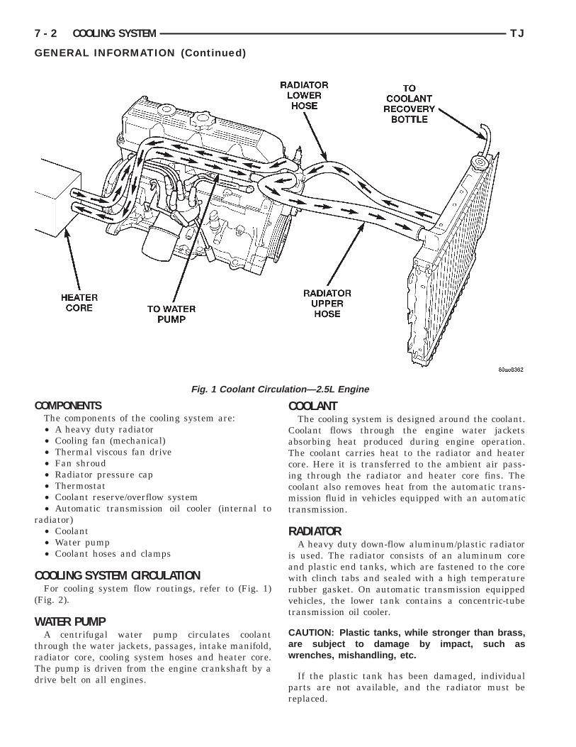
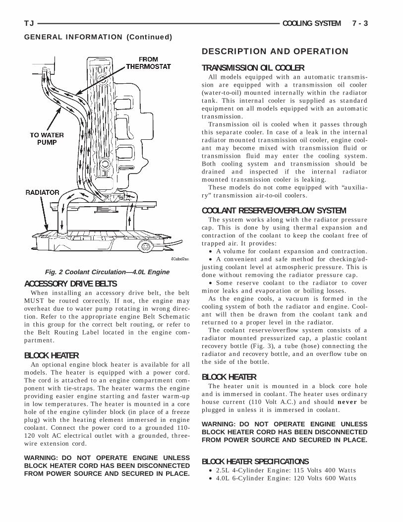
OOLING SYSTEM CIRCULATIONFor cooling system flow routings, refer to (Fig. 1)
Fig. 2).
ATER PUMPA centrifugal water pump circulates coolant
hrough the water jackets, passages, intake manifold,adiator core, cooling system hoses and heater core.he pump is driven from the engine crankshaft by arive belt on all engines.
Fig. 1 Coolant Circu
COOLANTThe cooling system is designed around the coolant.
Coolant flows through the engine water jacketsabsorbing heat produced during engine operation.The coolant carries heat to the radiator and heatercore. Here it is transferred to the ambient air pass-ing through the radiator and heater core fins. Thecoolant also removes heat from the automatic trans-mission fluid in vehicles equipped with an automatictransmission.
RADIATORA heavy duty down-flow aluminum/plastic radiator
is used. The radiator consists of an aluminum coreand plastic end tanks, which are fastened to the corewith clinch tabs and sealed with a high temperaturerubber gasket. On automatic transmission equippedvehicles, the lower tank contains a concentric-tubetransmission oil cooler.
CAUTION: Plastic tanks, while stronger than brass,are subject to damage by impact, such aswrenches, mishandling, etc.
If the plastic tank has been damaged, individualparts are not available, and the radiator must bereplaced.
n—2.5L Engine
A
Motitp
B
mTppihpc1w
WBF
p
WBF
TJ COOLING SYSTEM 7 - 3
GENERAL INFORMATION (Continued)
CCESSORY DRIVE BELTSWhen installing an accessory drive belt, the beltUST be routed correctly. If not, the engine may
verheat due to water pump rotating in wrong direc-ion. Refer to the appropriate engine Belt Schematicn this group for the correct belt routing, or refer tohe Belt Routing Label located in the engine com-artment.
LOCK HEATERAn optional engine block heater is available for allodels. The heater is equipped with a power cord.he cord is attached to an engine compartment com-onent with tie-straps. The heater warms the engineroviding easier engine starting and faster warm-upn low temperatures. The heater is mounted in a coreole of the engine cylinder block (in place of a freezelug) with the heating element immersed in engineoolant. Connect the power cord to a grounded 110-20 volt AC electrical outlet with a grounded, three-ire extension cord.
ARNING: DO NOT OPERATE ENGINE UNLESSLOCK HEATER CORD HAS BEEN DISCONNECTEDROM POWER SOURCE AND SECURED IN PLACE.
Fig. 2 Coolant Circulation—4.0L Engine
DESCRIPTION AND OPERATION
TRANSMISSION OIL COOLERAll models equipped with an automatic transmis-
sion are equipped with a transmission oil cooler(water-to-oil) mounted internally within the radiatortank. This internal cooler is supplied as standardequipment on all models equipped with an automatictransmission.
Transmission oil is cooled when it passes throughthis separate cooler. In case of a leak in the internalradiator mounted transmission oil cooler, engine cool-ant may become mixed with transmission fluid ortransmission fluid may enter the cooling system.Both cooling system and transmission should bedrained and inspected if the internal radiatormounted transmission cooler is leaking.
These models do not come equipped with “auxilia-ry” transmission air-to-oil coolers.
COOLANT RESERVE/OVERFLOW SYSTEMThe system works along with the radiator pressure
cap. This is done by using thermal expansion andcontraction of the coolant to keep the coolant free oftrapped air. It provides:
• A volume for coolant expansion and contraction.• A convenient and safe method for checking/ad-
justing coolant level at atmospheric pressure. This isdone without removing the radiator pressure cap.
• Some reserve coolant to the radiator to coverminor leaks and evaporation or boiling losses.
As the engine cools, a vacuum is formed in thecooling system of both the radiator and engine. Cool-ant will then be drawn from the coolant tank andreturned to a proper level in the radiator.
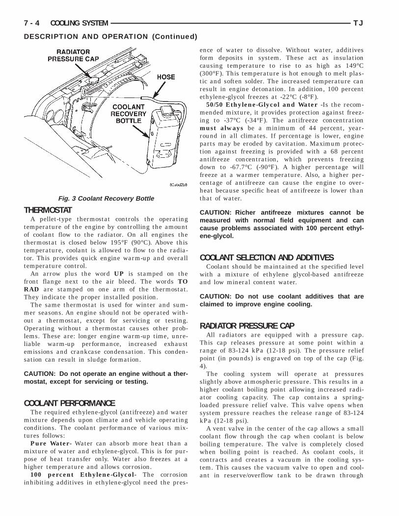
The coolant reserve/overflow system consists of aradiator mounted pressurized cap, a plastic coolantrecovery bottle (Fig. 3), a tube (hose) connecting theradiator and recovery bottle, and an overflow tube onthe side of the bottle.
BLOCK HEATERThe heater unit is mounted in a block core hole
and is immersed in coolant. The heater uses ordinaryhouse current (110 Volt A.C.) and should never be
lugged in unless it is immersed in coolant.
ARNING: DO NOT OPERATE ENGINE UNLESSLOCK HEATER CORD HAS BEEN DISCONNECTEDROM POWER SOURCE AND SECURED IN PLACE.
BLOCK HEATER SPECIFICATIONS• 2.5L 4-Cylinder Engine: 115 Volts 400 Watts• 4.0L 6-Cylinder Engine: 120 Volts 600 Watts
T
totttt
fRT
moOlles
Cm
C
mct
mph
i
7 - 4 COOLING SYSTEM TJ
DESCRIPTION AND OPERATION (Continued)
HERMOSTATA pellet-type thermostat controls the operating
emperature of the engine by controlling the amountf coolant flow to the radiator. On all engines thehermostat is closed below 195°F (90°C). Above thisemperature, coolant is allowed to flow to the radia-or. This provides quick engine warm-up and overallemperature control.
An arrow plus the word UP is stamped on theront flange next to the air bleed. The words TOAD are stamped on one arm of the thermostat.hey indicate the proper installed position.The same thermostat is used for winter and sum-er seasons. An engine should not be operated with-
ut a thermostat, except for servicing or testing.perating without a thermostat causes other prob-
ems. These are: longer engine warm-up time, unre-iable warm-up performance, increased exhaustmissions and crankcase condensation. This conden-ation can result in sludge formation.
AUTION: Do not operate an engine without a ther-ostat, except for servicing or testing.
OOLANT PERFORMANCEThe required ethylene-glycol (antifreeze) and waterixture depends upon climate and vehicle operating
onditions. The coolant performance of various mix-ures follows:
Pure Water- Water can absorb more heat than aixture of water and ethylene-glycol. This is for pur-
ose of heat transfer only. Water also freezes at aigher temperature and allows corrosion.100 percent Ethylene-Glycol- The corrosion
nhibiting additives in ethylene-glycol need the pres-
Fig. 3 Coolant Recovery Bottle
ence of water to dissolve. Without water, additivesform deposits in system. These act as insulationcausing temperature to rise to as high as 149°C(300°F). This temperature is hot enough to melt plas-tic and soften solder. The increased temperature canresult in engine detonation. In addition, 100 percentethylene-glycol freezes at -22°C (-8°F).
50/50 Ethylene-Glycol and Water -Is the recom-mended mixture, it provides protection against freez-ing to -37°C (-34°F). The antifreeze concentrationmust always be a minimum of 44 percent, year-round in all climates. If percentage is lower, engineparts may be eroded by cavitation. Maximum protec-tion against freezing is provided with a 68 percentantifreeze concentration, which prevents freezingdown to -67.7°C (-90°F). A higher percentage willfreeze at a warmer temperature. Also, a higher per-centage of antifreeze can cause the engine to over-heat because specific heat of antifreeze is lower thanthat of water.
CAUTION: Richer antifreeze mixtures cannot bemeasured with normal field equipment and cancause problems associated with 100 percent ethyl-ene-glycol.
COOLANT SELECTION AND ADDITIVESCoolant should be maintained at the specified level
with a mixture of ethylene glycol-based antifreezeand low mineral content water.
CAUTION: Do not use coolant additives that areclaimed to improve engine cooling.
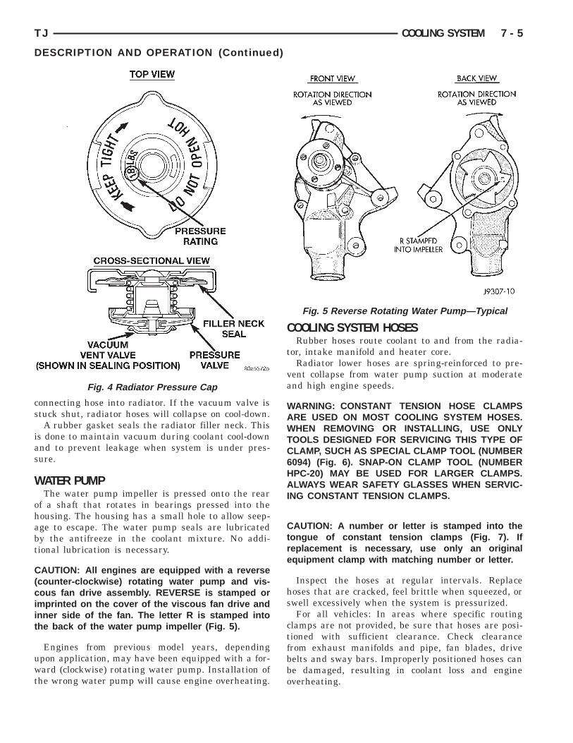
RADIATOR PRESSURE CAPAll radiators are equipped with a pressure cap.
This cap releases pressure at some point within arange of 83-124 kPa (12-18 psi). The pressure reliefpoint (in pounds) is engraved on top of the cap (Fig.4).
The cooling system will operate at pressuresslightly above atmospheric pressure. This results in ahigher coolant boiling point allowing increased radi-ator cooling capacity. The cap contains a spring-loaded pressure relief valve. This valve opens whensystem pressure reaches the release range of 83-124kPa (12-18 psi).
A vent valve in the center of the cap allows a smallcoolant flow through the cap when coolant is belowboiling temperature. The valve is completely closedwhen boiling point is reached. As coolant cools, itcontracts and creates a vacuum in the cooling sys-tem. This causes the vacuum valve to open and cool-ant in reserve/overflow tank to be drawn through
cs
ias
W
ohabt
C(ciit
uwt
TJ COOLING SYSTEM 7 - 5
DESCRIPTION AND OPERATION (Continued)
onnecting hose into radiator. If the vacuum valve istuck shut, radiator hoses will collapse on cool-down.A rubber gasket seals the radiator filler neck. This
s done to maintain vacuum during coolant cool-downnd to prevent leakage when system is under pres-ure.
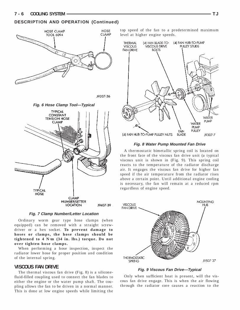
ATER PUMPThe water pump impeller is pressed onto the rear
f a shaft that rotates in bearings pressed into theousing. The housing has a small hole to allow seep-ge to escape. The water pump seals are lubricatedy the antifreeze in the coolant mixture. No addi-ional lubrication is necessary.
AUTION: All engines are equipped with a reversecounter-clockwise) rotating water pump and vis-ous fan drive assembly. REVERSE is stamped ormprinted on the cover of the viscous fan drive andnner side of the fan. The letter R is stamped intohe back of the water pump impeller (Fig. 5).
Engines from previous model years, dependingpon application, may have been equipped with a for-ard (clockwise) rotating water pump. Installation of
he wrong water pump will cause engine overheating.
Fig. 4 Radiator Pressure Cap
COOLING SYSTEM HOSESRubber hoses route coolant to and from the radia-
tor, intake manifold and heater core.Radiator lower hoses are spring-reinforced to pre-
vent collapse from water pump suction at moderateand high engine speeds.
WARNING: CONSTANT TENSION HOSE CLAMPSARE USED ON MOST COOLING SYSTEM HOSES.WHEN REMOVING OR INSTALLING, USE ONLYTOOLS DESIGNED FOR SERVICING THIS TYPE OFCLAMP, SUCH AS SPECIAL CLAMP TOOL (NUMBER6094) (Fig. 6). SNAP-ON CLAMP TOOL (NUMBERHPC-20) MAY BE USED FOR LARGER CLAMPS.ALWAYS WEAR SAFETY GLASSES WHEN SERVIC-ING CONSTANT TENSION CLAMPS.
CAUTION: A number or letter is stamped into thetongue of constant tension clamps (Fig. 7). Ifreplacement is necessary, use only an originalequipment clamp with matching number or letter.
Inspect the hoses at regular intervals. Replacehoses that are cracked, feel brittle when squeezed, orswell excessively when the system is pressurized.
For all vehicles: In areas where specific routingclamps are not provided, be sure that hoses are posi-tioned with sufficient clearance. Check clearancefrom exhaust manifolds and pipe, fan blades, drivebelts and sway bars. Improperly positioned hoses canbe damaged, resulting in coolant loss and engineoverheating.
Fig. 5 Reverse Rotating Water Pump—Typical
edhto
ro
V
fepT
7 - 6 COOLING SYSTEM TJ
DESCRIPTION AND OPERATION (Continued)
Ordinary worm gear type hose clamps (whenquipped) can be removed with a straight screw-river or a hex socket. To prevent damage tooses or clamps, the hose clamps should beightened to 4 N·m (34 in. lbs.) torque. Do notver tighten hose clamps.When performing a hose inspection, inspect the
adiator lower hose for proper position and conditionf the internal spring.
ISCOUS FAN DRIVEThe thermal viscous fan drive (Fig. 8) is a silicone-
luid-filled coupling used to connect the fan blades toither the engine or the water pump shaft. The cou-ling allows the fan to be driven in a normal manner.his is done at low engine speeds while limiting the
Fig. 6 Hose Clamp Tool—Typical
Fig. 7 Clamp Number/Letter Location
top speed of the fan to a predetermined maximumlevel at higher engine speeds.
A thermostatic bimetallic spring coil is located onthe front face of the viscous fan drive unit (a typicalviscous unit is shown in (Fig. 9). This spring coilreacts to the temperature of the radiator dischargeair. It engages the viscous fan drive for higher fanspeed if the air temperature from the radiator risesabove a certain point. Until additional engine coolingis necessary, the fan will remain at a reduced rpmregardless of engine speed.
Only when sufficient heat is present, will the vis-cous fan drive engage. This is when the air flowingthrough the radiator core causes a reaction to the
Fig. 8 Water Pump Mounted Fan Drive
Fig. 9 Viscous Fan Drive—Typical
bt
trd
Cbddoi
Cbbchbfaf
D
O
C
ps
pn
ta
osftp
A
rp
TJ COOLING SYSTEM 7 - 7
DESCRIPTION AND OPERATION (Continued)
imetallic coil. It then increases fan speed to providehe necessary additional engine cooling.
Once the engine has cooled, the radiator dischargeemperature will drop. The bimetallic coil againeacts and the fan speed is reduced to the previousisengaged speed.
AUTION: Engines equipped with serpentine driveelts have reverse rotating fans and viscous fanrives. They are marked with the word REVERSE toesignate their usage. Installation of the wrong fanr viscous fan drive can result in engine overheat-
ng.
AUTION: If the viscous fan drive is replacedecause of mechanical damage, the cooling fanlades should also be inspected. Inspect for fatigueracks, loose blades, or loose rivets that couldave resulted from excessive vibration. Replace fanlade assembly if any of these conditions are
ound. Also inspect water pump bearing and shaftssembly for any related damage due to a viscous
an drive malfunction.
IAGNOSIS AND TESTING
N-BOARD DIAGNOSTICS (OBD)
OOLING SYSTEM RELATED DIAGNOSTICSThe Powertrain Control Module (PCM) has been
rogrammed to monitor the certain following coolingystem components:• If the engine has remained cool for too long a
eriod, such as with a stuck open thermostat, a Diag-ostic Trouble Code (DTC) can be set.• If an open or shorted condition has developed in
he relay circuit controlling the electric radiator fan,Diagnostic Trouble Code (DTC) can be set.If the problem is sensed in a monitored circuit
ften enough to indicate an actual problem, a DTC istored. The DTC will be stored in the PCM memoryor eventual display to the service technician. (Refero Group 25, Emission Control Systems for properrocedures)
CCESSING DIAGNOSTIC TROUBLE CODESTo read DTC’s and to obtain cooling system data,
efer to Group 25, Emission Control Systems forroper procedures.
ACCESSORY DRIVE BELT DIAGNOSIS
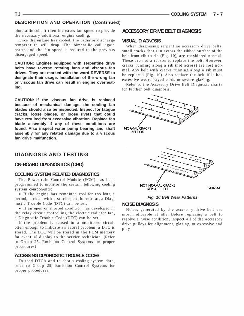
VISUAL DIAGNOSISWhen diagnosing serpentine accessory drive belts,
small cracks that run across the ribbed surface of thebelt from rib to rib (Fig. 10), are considered normal.These are not a reason to replace the belt. However,cracks running along a rib (not across) are not nor-mal. Any belt with cracks running along a rib mustbe replaced (Fig. 10). Also replace the belt if it hasexcessive wear, frayed cords or severe glazing.
Refer to the Accessory Drive Belt Diagnosis chartsfor further belt diagnosis.
NOISE DIAGNOSISNoises generated by the accessory drive belt are
most noticeable at idle. Before replacing a belt toresolve a noise condition, inspect all of the accessorydrive pulleys for alignment, glazing, or excessive endplay.
Fig. 10 Belt Wear Patterns
7 - 8 COOLING SYSTEM TJ
DIAGNOSIS AND TESTING (Continued)
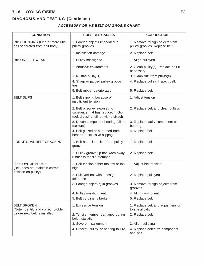
ACCESSORY DRIVE BELT DIAGNOSIS CHART
CONDITION POSSIBLE CAUSES CORRECTION
RIB CHUNKING (One or more ribshas separated from belt body)
1. Foreign objects imbedded inpulley grooves.
1. Remove foreign objects frompulley grooves. Replace belt.
2. Installation damage 2. Replace belt
RIB OR BELT WEAR 1. Pulley misaligned 1. Align pulley(s)
2. Abrasive environment 2. Clean pulley(s). Replace belt ifnecessary
3. Rusted pulley(s) 3. Clean rust from pulley(s)
4. Sharp or jagged pulley groovetips
4. Replace pulley. Inspect belt.
5. Belt rubber deteriorated 5. Replace belt
BELT SLIPS 1. Belt slipping because ofinsufficient tension
1. Adjust tension
2. Belt or pulley exposed tosubstance that has reduced friction(belt dressing, oil, ethylene glycol)
2. Replace belt and clean pulleys
3. Driven component bearing failure(seizure)
3. Replace faulty component orbearing
4. Belt glazed or hardened fromheat and excessive slippage
4. Replace belt.
LONGITUDAL BELT CRACKING 1. Belt has mistracked from pulleygroove
1. Replace belt
2. Pulley groove tip has worn awayrubber to tensile member
2. Replace belt
9GROOVE JUMPING9(Belt does not maintain correctposition on pulley)
1. Belt tension either too low or toohigh
1. Adjust belt tension
2. Pulley(s) not within designtolerance
2. Replace pulley(s)
3. Foreign object(s) in grooves 3. Remove foreign objects fromgrooves
4. Pulley misalignment 4. Align component
5. Belt cordline is broken 5. Replace belt
BELT BROKEN(Note: Identify and correct problembefore new belt is installed)
1. Excessive tension 1. Replace belt and adjust tensionto specification
2. Tensile member damaged duringbelt installation
2. Replace belt
3. Severe misalignment 3. Align pulley(s)
4. Bracket, pulley, or bearing failure 4. Replace defective componentand belt
P
E
pt
PSJ
e
o
T
D
A
c
TJ COOLING SYSTEM 7 - 9
DIAGNOSIS AND TESTING (Continued)
CONDITION POSSIBLE CAUSES CORRECTION
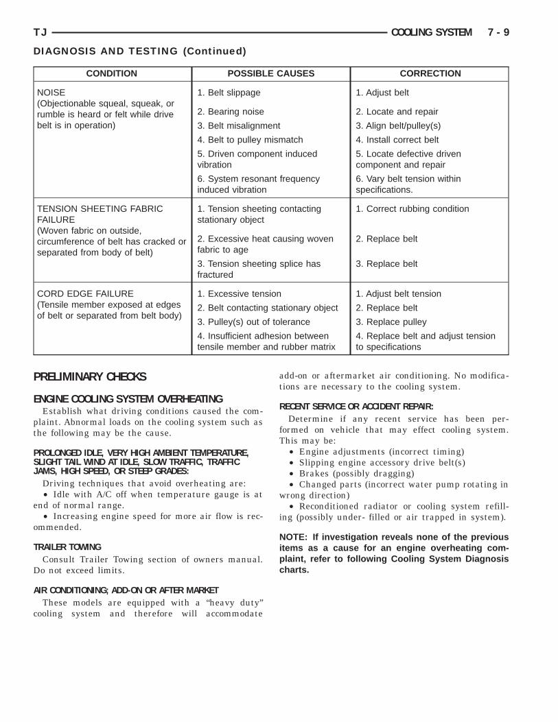
NOISE(Objectionable squeal, squeak, orrumble is heard or felt while drivebelt is in operation)
1. Belt slippage 1. Adjust belt
2. Bearing noise 2. Locate and repair
3. Belt misalignment 3. Align belt/pulley(s)
4. Belt to pulley mismatch 4. Install correct belt
5. Driven component inducedvibration
5. Locate defective drivencomponent and repair
6. System resonant frequencyinduced vibration
6. Vary belt tension withinspecifications.
TENSION SHEETING FABRICFAILURE(Woven fabric on outside,circumference of belt has cracked orseparated from body of belt)
1. Tension sheeting contactingstationary object
1. Correct rubbing condition
2. Excessive heat causing wovenfabric to age
2. Replace belt
3. Tension sheeting splice hasfractured
3. Replace belt
CORD EDGE FAILURE(Tensile member exposed at edgesof belt or separated from belt body)
1. Excessive tension 1. Adjust belt tension
2. Belt contacting stationary object 2. Replace belt
3. Pulley(s) out of tolerance 3. Replace pulley
4. Insufficient adhesion betweentensile member and rubber matrix
4. Replace belt and adjust tensionto specifications
RELIMINARY CHECKS
NGINE COOLING SYSTEM OVERHEATINGEstablish what driving conditions caused the com-
laint. Abnormal loads on the cooling system such ashe following may be the cause.
ROLONGED IDLE, VERY HIGH AMBIENT TEMPERATURE,LIGHT TAIL WIND AT IDLE, SLOW TRAFFIC, TRAFFICAMS, HIGH SPEED, OR STEEP GRADES:Driving techniques that avoid overheating are:• Idle with A/C off when temperature gauge is at
nd of normal range.• Increasing engine speed for more air flow is rec-
mmended.
RAILER TOWINGConsult Trailer Towing section of owners manual.o not exceed limits.
IR CONDITIONING; ADD-ON OR AFTER MARKETThese models are equipped with a “heavy duty”
ooling system and therefore will accommodate
add-on or aftermarket air conditioning. No modifica-tions are necessary to the cooling system.
RECENT SERVICE OR ACCIDENT REPAIR:Determine if any recent service has been per-
formed on vehicle that may effect cooling system.This may be:
• Engine adjustments (incorrect timing)• Slipping engine accessory drive belt(s)• Brakes (possibly dragging)• Changed parts (incorrect water pump rotating in
wrong direction)• Reconditioned radiator or cooling system refill-
ing (possibly under- filled or air trapped in system).
NOTE: If investigation reveals none of the previousitems as a cause for an engine overheating com-plaint, refer to following Cooling System Diagnosischarts.
C
7 - 10 COOLING SYSTEM TJ
DIAGNOSIS AND TESTING (Continued)
OOLING SYSTEM DIAGNOSISCOOLING SYSTEM DIAGNOSIS CHART
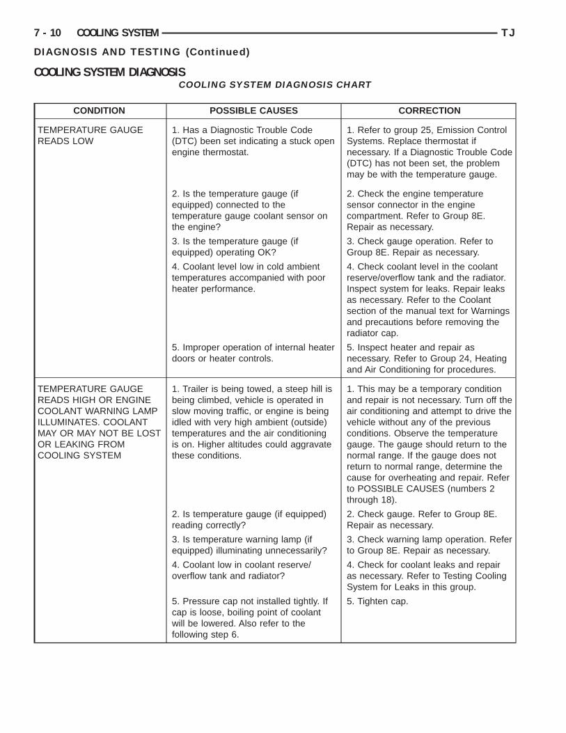
CONDITION POSSIBLE CAUSES CORRECTION
TEMPERATURE GAUGEREADS LOW
1. Has a Diagnostic Trouble Code(DTC) been set indicating a stuck openengine thermostat.
1. Refer to group 25, Emission ControlSystems. Replace thermostat ifnecessary. If a Diagnostic Trouble Code(DTC) has not been set, the problemmay be with the temperature gauge.
2. Is the temperature gauge (ifequipped) connected to thetemperature gauge coolant sensor onthe engine?
2. Check the engine temperaturesensor connector in the enginecompartment. Refer to Group 8E.Repair as necessary.
3. Is the temperature gauge (ifequipped) operating OK?
3. Check gauge operation. Refer toGroup 8E. Repair as necessary.
4. Coolant level low in cold ambienttemperatures accompanied with poorheater performance.
4. Check coolant level in the coolantreserve/overflow tank and the radiator.Inspect system for leaks. Repair leaksas necessary. Refer to the Coolantsection of the manual text for Warningsand precautions before removing theradiator cap.
5. Improper operation of internal heaterdoors or heater controls.
5. Inspect heater and repair asnecessary. Refer to Group 24, Heatingand Air Conditioning for procedures.
TEMPERATURE GAUGEREADS HIGH OR ENGINECOOLANT WARNING LAMPILLUMINATES. COOLANTMAY OR MAY NOT BE LOSTOR LEAKING FROMCOOLING SYSTEM
1. Trailer is being towed, a steep hill isbeing climbed, vehicle is operated inslow moving traffic, or engine is beingidled with very high ambient (outside)temperatures and the air conditioningis on. Higher altitudes could aggravatethese conditions.
1. This may be a temporary conditionand repair is not necessary. Turn off theair conditioning and attempt to drive thevehicle without any of the previousconditions. Observe the temperaturegauge. The gauge should return to thenormal range. If the gauge does notreturn to normal range, determine thecause for overheating and repair. Referto POSSIBLE CAUSES (numbers 2through 18).
2. Is temperature gauge (if equipped)reading correctly?
2. Check gauge. Refer to Group 8E.Repair as necessary.
3. Is temperature warning lamp (ifequipped) illuminating unnecessarily?
3. Check warning lamp operation. Referto Group 8E. Repair as necessary.
4. Coolant low in coolant reserve/overflow tank and radiator?
4. Check for coolant leaks and repairas necessary. Refer to Testing CoolingSystem for Leaks in this group.
5. Pressure cap not installed tightly. Ifcap is loose, boiling point of coolantwill be lowered. Also refer to thefollowing step 6.
5. Tighten cap.
TJ COOLING SYSTEM 7 - 11
DIAGNOSIS AND TESTING (Continued)
CONDITION POSSIBLE CAUSES CORRECTION
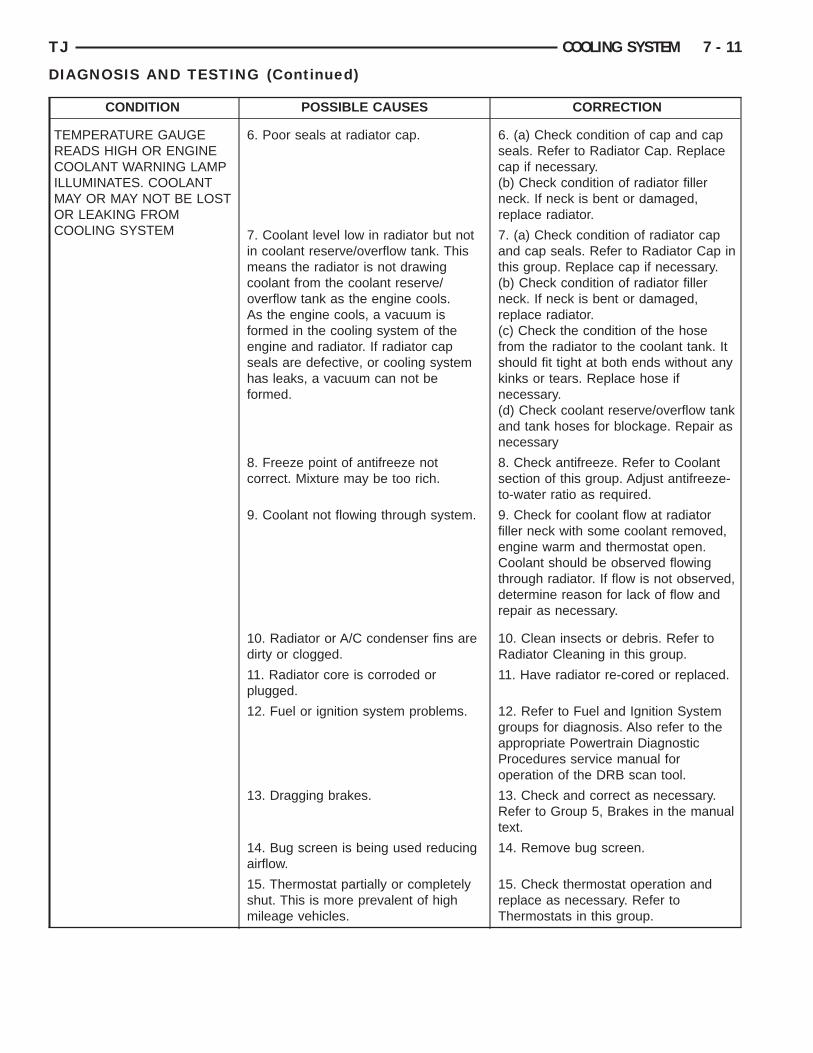
TEMPERATURE GAUGEREADS HIGH OR ENGINECOOLANT WARNING LAMPILLUMINATES. COOLANTMAY OR MAY NOT BE LOSTOR LEAKING FROMCOOLING SYSTEM
6. Poor seals at radiator cap. 6. (a) Check condition of cap and capseals. Refer to Radiator Cap. Replacecap if necessary.(b) Check condition of radiator fillerneck. If neck is bent or damaged,replace radiator.
7. Coolant level low in radiator but notin coolant reserve/overflow tank. Thismeans the radiator is not drawingcoolant from the coolant reserve/overflow tank as the engine cools.As the engine cools, a vacuum isformed in the cooling system of theengine and radiator. If radiator capseals are defective, or cooling systemhas leaks, a vacuum can not beformed.
7. (a) Check condition of radiator capand cap seals. Refer to Radiator Cap inthis group. Replace cap if necessary.(b) Check condition of radiator fillerneck. If neck is bent or damaged,replace radiator.(c) Check the condition of the hosefrom the radiator to the coolant tank. Itshould fit tight at both ends without anykinks or tears. Replace hose ifnecessary.(d) Check coolant reserve/overflow tankand tank hoses for blockage. Repair asnecessary
8. Freeze point of antifreeze notcorrect. Mixture may be too rich.
8. Check antifreeze. Refer to Coolantsection of this group. Adjust antifreeze-to-water ratio as required.
9. Coolant not flowing through system. 9. Check for coolant flow at radiatorfiller neck with some coolant removed,engine warm and thermostat open.Coolant should be observed flowingthrough radiator. If flow is not observed,determine reason for lack of flow andrepair as necessary.
10. Radiator or A/C condenser fins aredirty or clogged.
10. Clean insects or debris. Refer toRadiator Cleaning in this group.
11. Radiator core is corroded orplugged.
11. Have radiator re-cored or replaced.
12. Fuel or ignition system problems. 12. Refer to Fuel and Ignition Systemgroups for diagnosis. Also refer to theappropriate Powertrain DiagnosticProcedures service manual foroperation of the DRB scan tool.
13. Dragging brakes. 13. Check and correct as necessary.Refer to Group 5, Brakes in the manualtext.
14. Bug screen is being used reducingairflow.
14. Remove bug screen.
15. Thermostat partially or completelyshut. This is more prevalent of highmileage vehicles.
15. Check thermostat operation andreplace as necessary. Refer toThermostats in this group.
7 - 12 COOLING SYSTEM TJ
DIAGNOSIS AND TESTING (Continued)
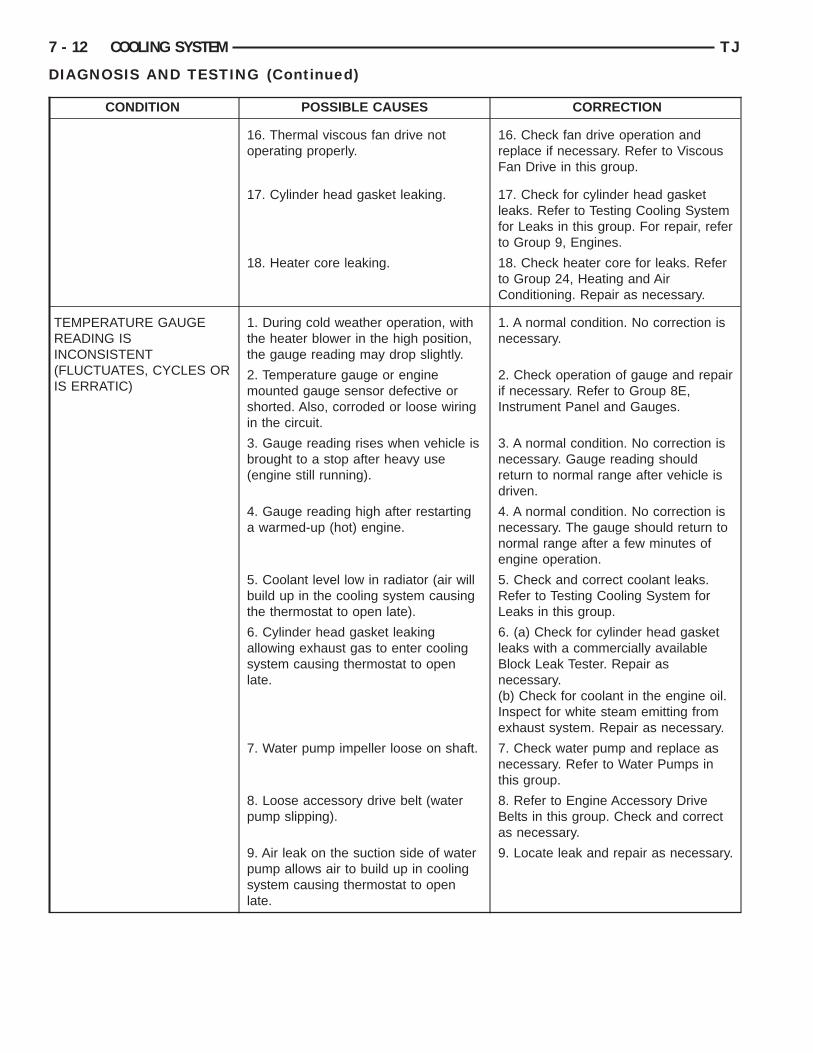
CONDITION POSSIBLE CAUSES CORRECTION
16. Thermal viscous fan drive notoperating properly.
16. Check fan drive operation andreplace if necessary. Refer to ViscousFan Drive in this group.
17. Cylinder head gasket leaking. 17. Check for cylinder head gasketleaks. Refer to Testing Cooling Systemfor Leaks in this group. For repair, referto Group 9, Engines.
18. Heater core leaking. 18. Check heater core for leaks. Referto Group 24, Heating and AirConditioning. Repair as necessary.
TEMPERATURE GAUGEREADING ISINCONSISTENT(FLUCTUATES, CYCLES ORIS ERRATIC)
1. During cold weather operation, withthe heater blower in the high position,the gauge reading may drop slightly.
1. A normal condition. No correction isnecessary.
2. Temperature gauge or enginemounted gauge sensor defective orshorted. Also, corroded or loose wiringin the circuit.
2. Check operation of gauge and repairif necessary. Refer to Group 8E,Instrument Panel and Gauges.
3. Gauge reading rises when vehicle isbrought to a stop after heavy use(engine still running).
3. A normal condition. No correction isnecessary. Gauge reading shouldreturn to normal range after vehicle isdriven.
4. Gauge reading high after restartinga warmed-up (hot) engine.
4. A normal condition. No correction isnecessary. The gauge should return tonormal range after a few minutes ofengine operation.
5. Coolant level low in radiator (air willbuild up in the cooling system causingthe thermostat to open late).
5. Check and correct coolant leaks.Refer to Testing Cooling System forLeaks in this group.
6. Cylinder head gasket leakingallowing exhaust gas to enter coolingsystem causing thermostat to openlate.
6. (a) Check for cylinder head gasketleaks with a commercially availableBlock Leak Tester. Repair asnecessary.(b) Check for coolant in the engine oil.Inspect for white steam emitting fromexhaust system. Repair as necessary.
7. Water pump impeller loose on shaft. 7. Check water pump and replace asnecessary. Refer to Water Pumps inthis group.
8. Loose accessory drive belt (waterpump slipping).
8. Refer to Engine Accessory DriveBelts in this group. Check and correctas necessary.
9. Air leak on the suction side of waterpump allows air to build up in coolingsystem causing thermostat to openlate.
9. Locate leak and repair as necessary.
TJ COOLING SYSTEM 7 - 13
DIAGNOSIS AND TESTING (Continued)
CONDITION POSSIBLE CAUSES CORRECTION
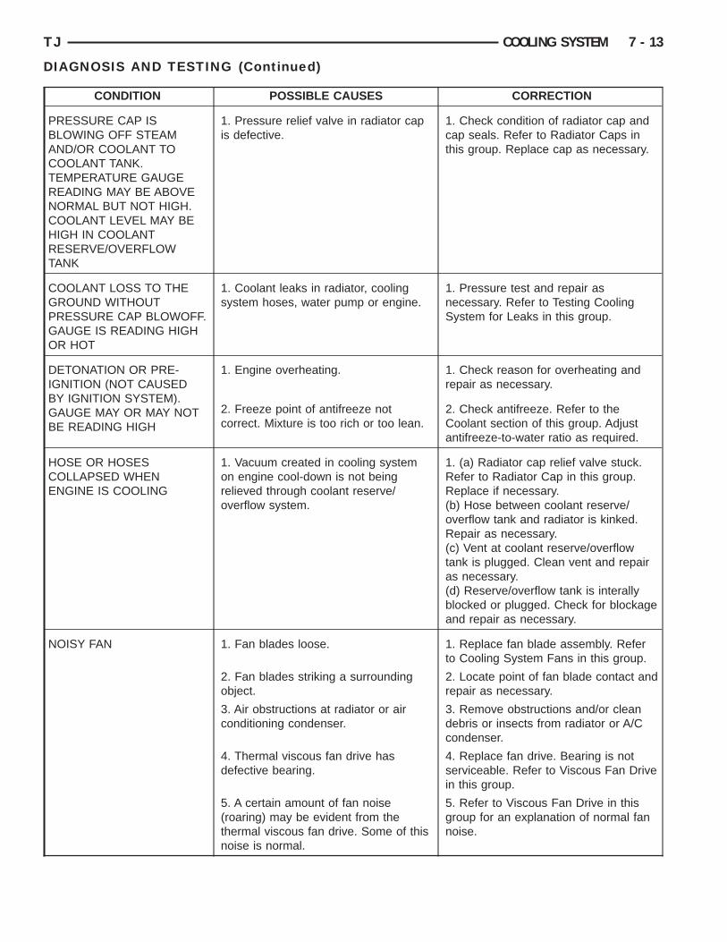
PRESSURE CAP ISBLOWING OFF STEAMAND/OR COOLANT TOCOOLANT TANK.TEMPERATURE GAUGEREADING MAY BE ABOVENORMAL BUT NOT HIGH.COOLANT LEVEL MAY BEHIGH IN COOLANTRESERVE/OVERFLOWTANK
1. Pressure relief valve in radiator capis defective.
1. Check condition of radiator cap andcap seals. Refer to Radiator Caps inthis group. Replace cap as necessary.
COOLANT LOSS TO THEGROUND WITHOUTPRESSURE CAP BLOWOFF.GAUGE IS READING HIGHOR HOT
1. Coolant leaks in radiator, coolingsystem hoses, water pump or engine.
1. Pressure test and repair asnecessary. Refer to Testing CoolingSystem for Leaks in this group.
DETONATION OR PRE-IGNITION (NOT CAUSEDBY IGNITION SYSTEM).GAUGE MAY OR MAY NOTBE READING HIGH
1. Engine overheating. 1. Check reason for overheating andrepair as necessary.
2. Freeze point of antifreeze notcorrect. Mixture is too rich or too lean.
2. Check antifreeze. Refer to theCoolant section of this group. Adjustantifreeze-to-water ratio as required.
HOSE OR HOSESCOLLAPSED WHENENGINE IS COOLING
1. Vacuum created in cooling systemon engine cool-down is not beingrelieved through coolant reserve/overflow system.
1. (a) Radiator cap relief valve stuck.Refer to Radiator Cap in this group.Replace if necessary.(b) Hose between coolant reserve/overflow tank and radiator is kinked.Repair as necessary.(c) Vent at coolant reserve/overflowtank is plugged. Clean vent and repairas necessary.(d) Reserve/overflow tank is interallyblocked or plugged. Check for blockageand repair as necessary.
NOISY FAN 1. Fan blades loose. 1. Replace fan blade assembly. Referto Cooling System Fans in this group.
2. Fan blades striking a surroundingobject.
2. Locate point of fan blade contact andrepair as necessary.
3. Air obstructions at radiator or airconditioning condenser.
3. Remove obstructions and/or cleandebris or insects from radiator or A/Ccondenser.
4. Thermal viscous fan drive hasdefective bearing.
4. Replace fan drive. Bearing is notserviceable. Refer to Viscous Fan Drivein this group.
5. A certain amount of fan noise(roaring) may be evident from thethermal viscous fan drive. Some of thisnoise is normal.
5. Refer to Viscous Fan Drive in thisgroup for an explanation of normal fannoise.
7 - 14 COOLING SYSTEM TJ
DIAGNOSIS AND TESTING (Continued)
CONDITION POSSIBLE CAUSES CORRECTION
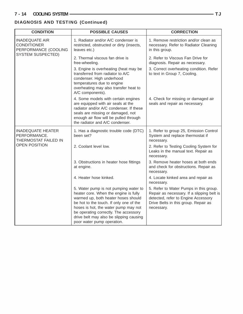
INADEQUATE AIRCONDITIONERPERFORMANCE (COOLINGSYSTEM SUSPECTED)
1. Radiator and/or A/C condenser isrestricted, obstructed or dirty (insects,leaves etc.)
1. Remove restriction and/or clean asnecessary. Refer to Radiator Cleaningin this group.
2. Thermal viscous fan drive isfree-wheeling.
2. Refer to Viscous Fan Drive fordiagnosis. Repair as necessary.
3. Engine is overheating (heat may betransferred from radiator to A/Ccondenser. High underhoodtemperatures due to engineoverheating may also transfer heat toA/C components).
3. Correct overheating condition. Referto text in Group 7, Cooling.
4. Some models with certain enginesare equipped with air seals at theradiator and/or A/C condenser. If theseseals are missing or damaged, notenough air flow will be pulled throughthe radiator and A/C condenser.
4. Check for missing or damaged airseals and repair as necessary.
INADEQUATE HEATERPERFORMANCE.THERMOSTAT FAILED INOPEN POSITION
1. Has a diagnostic trouble code (DTC)been set?
1. Refer to group 25, Emission ControlSystem and replace thermostat ifnecessary.
2. Coolant level low. 2. Refer to Testing Cooling System forLeaks in the manual text. Repair asnecessary.
3. Obstructions in heater hose fittingsat engine.
3. Remove heater hoses at both endsand check for obstructions. Repair asnecessary.
4. Heater hose kinked. 4. Locate kinked area and repair asnecessary.
5. Water pump is not pumping water toheater core. When the engine is fullywarmed up, both heater hoses shouldbe hot to the touch. If only one of thehoses is hot, the water pump may notbe operating correctly. The accessorydrive belt may also be slipping causingpoor water pump operation.
5. Refer to Water Pumps in this group.Repair as necessary. If a slipping belt isdetected, refer to Engine AccessoryDrive Belts in this group. Repair asnecessary.
TJ COOLING SYSTEM 7 - 15
DIAGNOSIS AND TESTING (Continued)
CONDITION POSSIBLE CAUSES CORRECTION
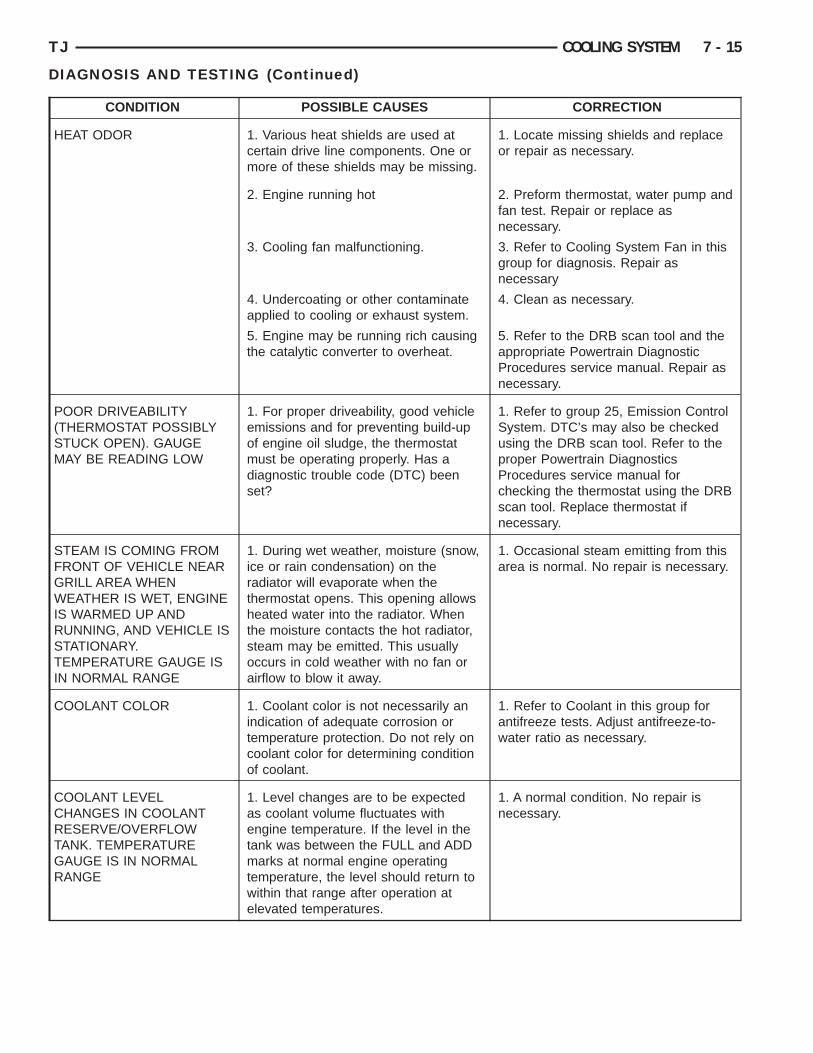
HEAT ODOR 1. Various heat shields are used atcertain drive line components. One ormore of these shields may be missing.
1. Locate missing shields and replaceor repair as necessary.
2. Engine running hot 2. Preform thermostat, water pump andfan test. Repair or replace asnecessary.
3. Cooling fan malfunctioning. 3. Refer to Cooling System Fan in thisgroup for diagnosis. Repair asnecessary
4. Undercoating or other contaminateapplied to cooling or exhaust system.
4. Clean as necessary.
5. Engine may be running rich causingthe catalytic converter to overheat.
5. Refer to the DRB scan tool and theappropriate Powertrain DiagnosticProcedures service manual. Repair asnecessary.
POOR DRIVEABILITY(THERMOSTAT POSSIBLYSTUCK OPEN). GAUGEMAY BE READING LOW
1. For proper driveability, good vehicleemissions and for preventing build-upof engine oil sludge, the thermostatmust be operating properly. Has adiagnostic trouble code (DTC) beenset?
1. Refer to group 25, Emission ControlSystem. DTC’s may also be checkedusing the DRB scan tool. Refer to theproper Powertrain DiagnosticsProcedures service manual forchecking the thermostat using the DRBscan tool. Replace thermostat ifnecessary.
STEAM IS COMING FROMFRONT OF VEHICLE NEARGRILL AREA WHENWEATHER IS WET, ENGINEIS WARMED UP ANDRUNNING, AND VEHICLE ISSTATIONARY.TEMPERATURE GAUGE ISIN NORMAL RANGE
1. During wet weather, moisture (snow,ice or rain condensation) on theradiator will evaporate when thethermostat opens. This opening allowsheated water into the radiator. Whenthe moisture contacts the hot radiator,steam may be emitted. This usuallyoccurs in cold weather with no fan orairflow to blow it away.
1. Occasional steam emitting from thisarea is normal. No repair is necessary.
COOLANT COLOR 1. Coolant color is not necessarily anindication of adequate corrosion ortemperature protection. Do not rely oncoolant color for determining conditionof coolant.
1. Refer to Coolant in this group forantifreeze tests. Adjust antifreeze-to-water ratio as necessary.
COOLANT LEVELCHANGES IN COOLANTRESERVE/OVERFLOWTANK. TEMPERATUREGAUGE IS IN NORMALRANGE
1. Level changes are to be expectedas coolant volume fluctuates withengine temperature. If the level in thetank was between the FULL and ADDmarks at normal engine operatingtemperature, the level should return towithin that range after operation atelevated temperatures.
1. A normal condition. No repair isnecessary.
R
f
thi
C
U
atlbcpHttcbg
t1
P
pci
7 - 16 COOLING SYSTEM TJ
DIAGNOSIS AND TESTING (Continued)
ADIATOR COOLANT FLOW CHECKThe following procedure will determine if coolant is
lowing through the cooling system.If engine is cold, idle engine until normal operating
emperature is reached. Then feel the upper radiatorose. If hose is hot, the thermostat is open and water
s circulating through cooling system.
OOLING SYSTEM—TESTING FOR LEAKS
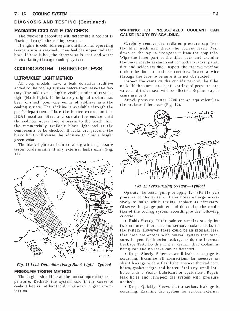
LTRAVIOLET LIGHT METHODAll Jeep models have a leak detection additive
dded to the cooling system before they leave the fac-ory. The additive is highly visible under ultravioletight (black light). If the factory original coolant haseen drained, pour one ounce of additive into theooling system. The additive is available through theart’s department. Place the heater control unit inEAT position. Start and operate the engine until
he radiator upper hose is warm to the touch. Aimhe commercially available black light tool at theomponents to be checked. If leaks are present, thelack light will cause the additive to glow a brightreen color.The black light can be used along with a pressure
ester to determine if any external leaks exist (Fig.1).
RESSURE TESTER METHODThe engine should be at the normal operating tem-
erature. Recheck the system cold if the cause ofoolant loss is not located during warm engine exam-nation.
Fig. 11 Leak Detection Using Black Light—Typical
WARNING: HOT, PRESSURIZED COOLANT CANCAUSE INJURY BY SCALDING.
Carefully remove the radiator pressure cap fromthe filler neck and check the coolant level. Pushdown on the cap to disengage it from the stop tabs.Wipe the inner part of the filler neck and examinethe lower inside sealing seat for nicks, cracks, paint,dirt and solder residue. Inspect the reserve/overflowtank tube for internal obstructions. Insert a wirethrough the tube to be sure it is not obstructed.
Inspect the cams on the outside part of the fillerneck. If the cams are bent, seating of pressure capvalve and tester seal will be affected. Replace cap ifcams are bent.
Attach pressure tester 7700 (or an equivalent) tothe radiator filler neck (Fig. 12).
Operate the tester pump to apply 124 kPa (18 psi)pressure to the system. If the hoses enlarge exces-sively or bulge while testing, replace as necessary.Observe the gauge pointer and determine the condi-tion of the cooling system according to the followingcriteria:
• Holds Steady: If the pointer remains steady fortwo minutes, there are no serious coolant leaks inthe system. However, there could be an internal leakthat does not appear with normal system test pres-sure. Inspect for interior leakage or do the InternalLeakage Test. Do this if it is certain that coolant isbeing lost and no leaks can be detected.
• Drops Slowly: Shows a small leak or seepage isoccurring. Examine all connections for seepage orslight leakage with a flashlight. Inspect the radiator,hoses, gasket edges and heater. Seal any small leakholes with a Sealer Lubricant or equivalent. Repairleak holes and reinspect the system with pressureapplied.
• Drops Quickly: Shows that a serious leakage isoccurring. Examine the system for serious external
Fig. 12 Pressurizing System—Typical
llb
I
stiuaufc
sfR
WETFT1
twpi
WP
Cpc
ssfo
CP
ir
WBDPC
TJ COOLING SYSTEM 7 - 17
DIAGNOSIS AND TESTING (Continued)
eakage. If no leaks are visible, inspect for internaleakage. Large radiator leak holes should be repairedy a reputable radiator repair shop.
NTERNAL LEAKAGE INSPECTIONRemove the engine oil pan drain plug and drain a
mall amount of engine oil. Coolant, being heavierhan engine oil, will drain first. Another way of test-ng is to operate the engine and check for water glob-les on the engine oil dipstick. Also inspect theutomatic transmission oil dipstick for water glob-les. Inspect the automatic transmission fluid cooleror leakage. Operate the engine without the pressureap on the radiator until thermostat opens.Attach a pressure tester to the filler neck. If pres-
ure builds up quickly, a leak exists as a result of aaulty cylinder head gasket or crack in the engine.epair as necessary.
ARNING: DO NOT ALLOW PRESSURE TOXCEED 124 KPA (18 PSI). TURN THE ENGINE OFF.O RELEASE THE PRESSURE, ROCK THE TESTERROM SIDE TO SIDE. WHEN REMOVING THEESTER, DO NOT TURN THE TESTER MORE THAN/2 TURN IF THE SYSTEM IS UNDER PRESSURE.
If there is no immediate pressure increase, pumphe pressure tester until the indicated pressure isithin the system range. Vibration of the gaugeointer indicates compression or combustion leakagento the cooling system.
ARNING: DO NOT DISCONNECT THE SPARKLUG WIRES WHILE THE ENGINE IS OPERATING.
AUTION: Do not operate the engine with a sparklug shorted for more than a minute. The catalyticonverter may be damaged.
Isolate the compression leak by shorting eachpark plug to the cylinder block. The gauge pointerhould stop or decrease vibration when spark plugor leaking cylinder is shorted. This happens becausef the absence of combustion pressure.
OMBUSTION LEAKAGE TEST (WITHOUTRESSURE TESTER)DO NOT WASTE reusable coolant. If the solution
s clean, drain the coolant into a clean container foreuse.
ARNING: DO NOT REMOVE THE CYLINDERLOCK DRAIN PLUGS OR LOOSEN THE RADIATORRAINCOCK WITH THE SYSTEM HOT AND UNDERRESSURE. SERIOUS BURNS FROM COOLANTAN OCCUR.
Drain sufficient coolant to allow for thermostatremoval. Refer to Thermostat Replacement. Discon-nect the water pump drive belt.
Disconnect the upper radiator hose from the ther-mostat housing. Remove the housing and thermostat.Install the thermostat housing.
Add coolant to the radiator to bring the level towithin 6.3 mm (1/4 in) of the top of the thermostathousing.
CAUTION: Avoid overheating. Do not operate theengine for an excessive period of time. Open thedraincock immediately after the test to eliminateboil over of coolant.
Start the engine and accelerate rapidly three times(to approximately 3000 rpm) while observing thecoolant. If internal engine combustion gases are leak-ing into the cooling system, bubbles will appear inthe coolant. If bubbles do not appear, there is nointernal combustion gas leakage.
VISCOUS FAN DRIVE
NOISE
NOTE: It is normal for fan noise to be louder (roar-ing) when:
• The underhood temperature is above the engage-ment point for the viscous drive coupling. This mayoccur when ambient (outside air temperature) is veryhigh.
• Engine loads and temperatures are high such aswhen towing a trailer.
• Cool silicone fluid within the fan drive unit isbeing redistributed back to its normal disengaged(warm) position. This can occur during the first 15seconds to one minute after engine start-up on a coldengine.
LEAKSViscous fan drive operation is not affected by small
oil stains near the drive bearing. If leakage appearsexcessive, replace the fan drive unit.
TESTINGIf the fan assembly free-wheels without drag (the
fan blades will revolve more than five turns whenspun by hand), replace the fan drive. This spin testmust be performed when the engine is cool.
For the following test, the cooling system must bein good condition. It also will ensure against exces-sively high coolant temperature.
WARNING: BE SURE THAT THERE IS ADEQUATEFAN BLADE CLEARANCE BEFORE DRILLING.
t
(1hc
tl
adp
t
WEDHN
WtFamfc
Fm8ft
Cbddoi
Cbbchbfaf
7 - 18 COOLING SYSTEM TJ
DIAGNOSIS AND TESTING (Continued)
(1) Drill a 3.18-mm (1/8-in) diameter hole in theop center of the fan shroud.
(2) Obtain a dial thermometer with an 8 inch stemor equivalent). It should have a range of -18°-to-05°C (0°-to-220° F). Insert thermometer through theole in the shroud. Be sure that there is adequatelearance from the fan blades.(3) Connect a tachometer and an engine ignition
iming light (timing light is to be used as a strobeight).
(4) Block the air flow through the radiator. Securesheet of plastic in front of the radiator (or air con-
itioner condenser). Use tape at the top to secure thelastic and be sure that the air flow is blocked.(5) Be sure that the air conditioner (if equipped) is
urned off.
ARNING: USE EXTREME CAUTION WHEN THENGINE IS OPERATING. DO NOT STAND IN AIRECT LINE WITH THE FAN. DO NOT PUT YOURANDS NEAR THE PULLEYS, BELTS OR FAN. DOOT WEAR LOOSE CLOTHING.
(6) Start the engine and operate at 2400 rpm.ithin ten minutes the air temperature (indicated on
he dial thermometer) should be up to 88° C (190° F).an drive engagement should have started to occurt between 74° to 85° C (165° to 185° F). Engage-ent is distinguishable by a definite increase in fan
low noise (roaring). The timing light also will indi-ate an increase in the speed of the fan.(7) When the air temperature reaches 88° C (190°
), remove the plastic sheet. Fan drive disengage-ent should have started to occur at between 57° to
2° C (135° to 180° F). A definite decrease of fanlow noise (roaring) should be noticed. If not, replacehe defective viscous fan drive unit.
AUTION: Engines equipped with serpentine driveelts have reverse rotating fans and viscous fanrives. They are marked with the word REVERSE toesignate their usage. Installation of the wrong fanr viscous fan drive can result in engine overheat-
ng.
AUTION: If the viscous fan drive is replacedecause of mechanical damage, the cooling fanlades should also be inspected. Inspect for fatigueracks, loose blades, or loose rivets that couldave resulted from excessive vibration. Replace fanlade assembly if any of these conditions are
ound. Also inspect water pump bearing and shaftssembly for any related damage due to a viscous
an drive malfunction.
RADIATOR CAP TO FILLER NECK SEAL—PRESSURE RELIEF CHECK
With radiator cap installed on filler neck, removecoolant reserve/overflow tank hose from nipple onfiller neck. Connect a hand operated vacuum pumpto nipple. Operate pump until a reading of 47 to 61kPa (14 to 18 in. Hg) appears on gauge. If the read-ing stays steady, or drops slightly and then remainssteady, the pressure valve seal is good. Replace radi-ator cap if reading does not hold.
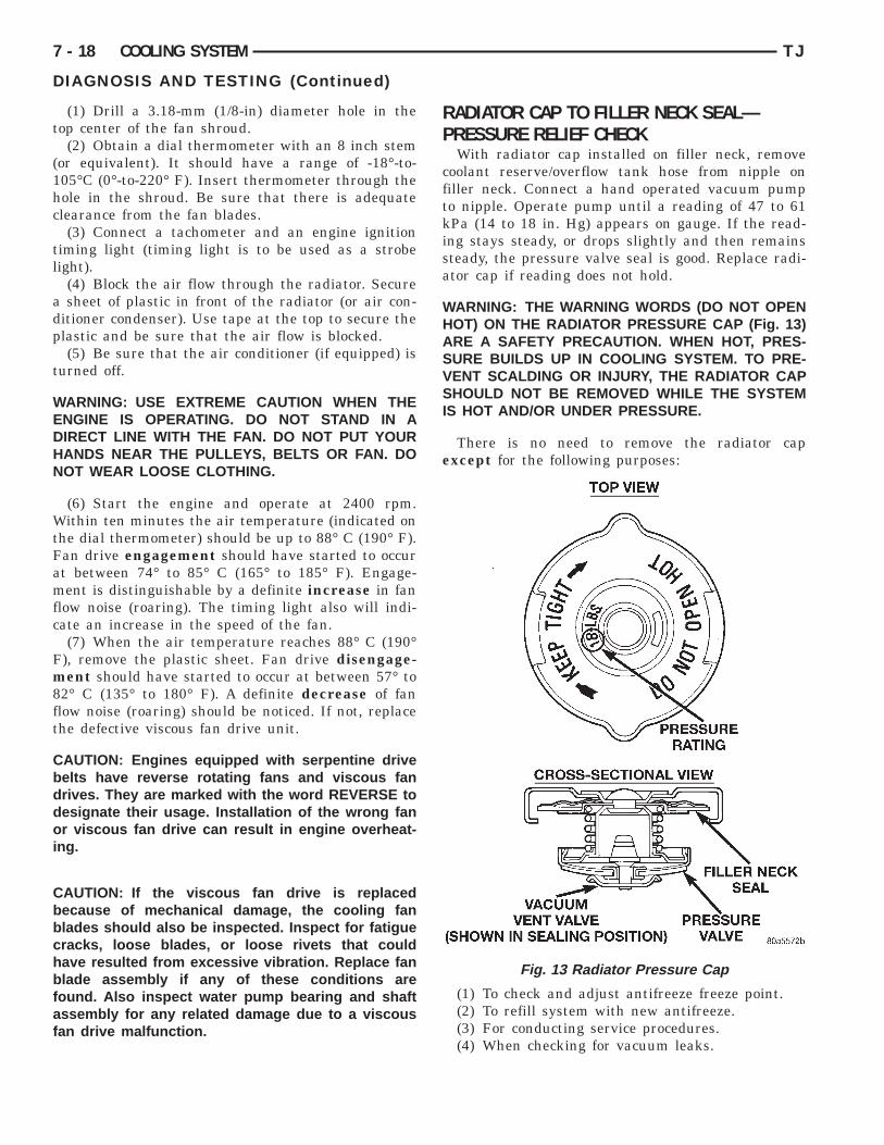
WARNING: THE WARNING WORDS (DO NOT OPENHOT) ON THE RADIATOR PRESSURE CAP (Fig. 13)ARE A SAFETY PRECAUTION. WHEN HOT, PRES-SURE BUILDS UP IN COOLING SYSTEM. TO PRE-VENT SCALDING OR INJURY, THE RADIATOR CAPSHOULD NOT BE REMOVED WHILE THE SYSTEMIS HOT AND/OR UNDER PRESSURE.
There is no need to remove the radiator capexcept for the following purposes:
(1) To check and adjust antifreeze freeze point.(2) To refill system with new antifreeze.(3) For conducting service procedures.(4) When checking for vacuum leaks.
Fig. 13 Radiator Pressure Cap
WWRUPWCAHTDRBSP
R
saa
pssgtd
Cs
TJ COOLING SYSTEM 7 - 19
DIAGNOSIS AND TESTING (Continued)
ARNING: IF VEHICLE HAS BEEN RUN RECENTLY,AIT AT LEAST 15 MINUTES BEFORE REMOVINGADIATOR CAP. WITH A RAG, SQUEEZE RADIATORPPER HOSE TO CHECK IF SYSTEM IS UNDERRESSURE. PLACE A RAG OVER THE CAP ANDITHOUT PUSHING DOWN, ROTATE CAPOUNTER-CLOCKWISE TO THE FIRST STOP.LLOW FLUID TO ESCAPE THROUGH OVERFLOWOSE INTO COOLANT RESERVE/OVERFLOWANK. SQUEEZE RADIATOR UPPER HOSE TOETERMINE WHEN PRESSURE HAS BEENELEASED. WHEN COOLANT AND STEAM STOPEING PUSHED INTO TANK AND SYSTEM PRES-URE DROPS, REMOVE RADIATOR CAP COM-LETELY.
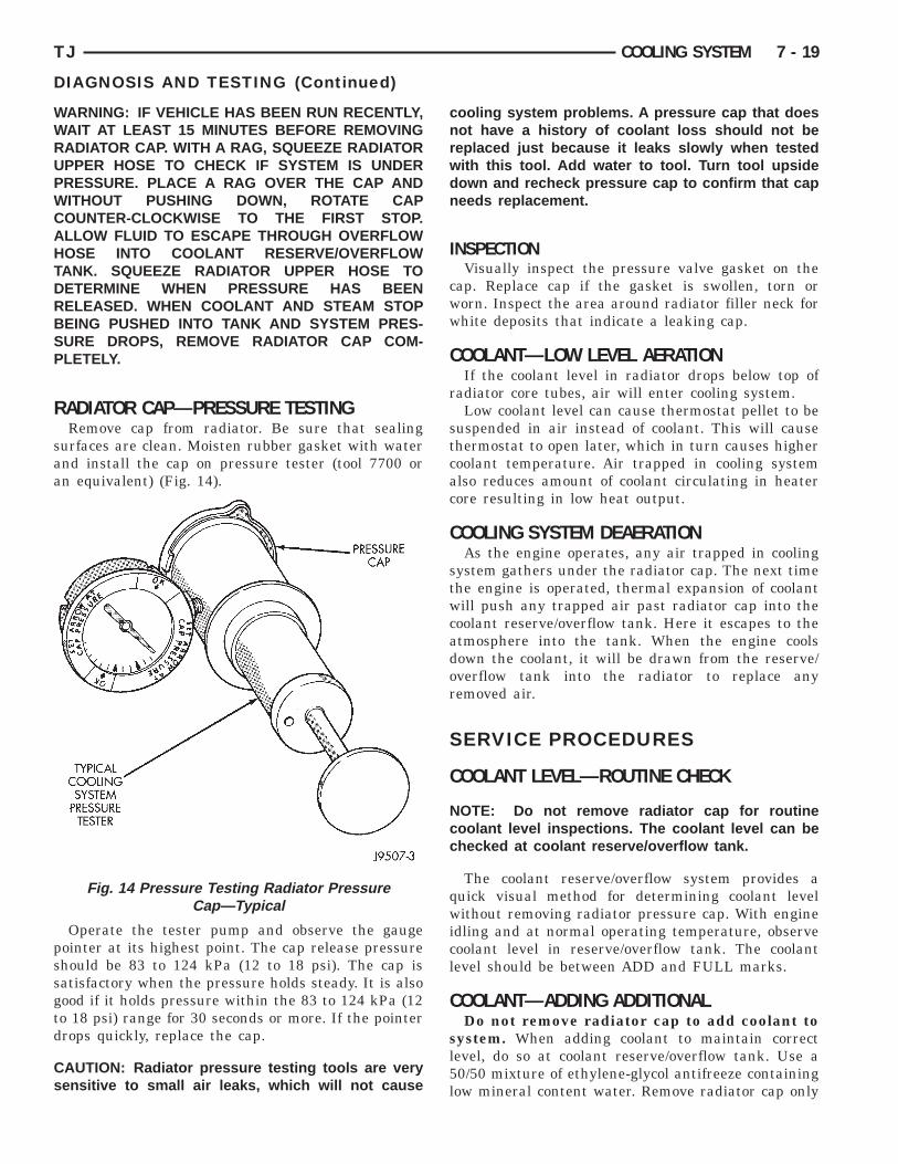
ADIATOR CAP—PRESSURE TESTINGRemove cap from radiator. Be sure that sealing
urfaces are clean. Moisten rubber gasket with waternd install the cap on pressure tester (tool 7700 orn equivalent) (Fig. 14).
Operate the tester pump and observe the gaugeointer at its highest point. The cap release pressurehould be 83 to 124 kPa (12 to 18 psi). The cap isatisfactory when the pressure holds steady. It is alsoood if it holds pressure within the 83 to 124 kPa (12o 18 psi) range for 30 seconds or more. If the pointerrops quickly, replace the cap.
AUTION: Radiator pressure testing tools are veryensitive to small air leaks, which will not cause
Fig. 14 Pressure Testing Radiator PressureCap—Typical
cooling system problems. A pressure cap that doesnot have a history of coolant loss should not bereplaced just because it leaks slowly when testedwith this tool. Add water to tool. Turn tool upsidedown and recheck pressure cap to confirm that capneeds replacement.
INSPECTIONVisually inspect the pressure valve gasket on the
cap. Replace cap if the gasket is swollen, torn orworn. Inspect the area around radiator filler neck forwhite deposits that indicate a leaking cap.
COOLANT—LOW LEVEL AERATIONIf the coolant level in radiator drops below top of
radiator core tubes, air will enter cooling system.Low coolant level can cause thermostat pellet to be
suspended in air instead of coolant. This will causethermostat to open later, which in turn causes highercoolant temperature. Air trapped in cooling systemalso reduces amount of coolant circulating in heatercore resulting in low heat output.
COOLING SYSTEM DEAERATIONAs the engine operates, any air trapped in cooling
system gathers under the radiator cap. The next timethe engine is operated, thermal expansion of coolantwill push any trapped air past radiator cap into thecoolant reserve/overflow tank. Here it escapes to theatmosphere into the tank. When the engine coolsdown the coolant, it will be drawn from the reserve/overflow tank into the radiator to replace anyremoved air.
SERVICE PROCEDURES
COOLANT LEVEL—ROUTINE CHECK
NOTE: Do not remove radiator cap for routinecoolant level inspections. The coolant level can bechecked at coolant reserve/overflow tank.
The coolant reserve/overflow system provides aquick visual method for determining coolant levelwithout removing radiator pressure cap. With engineidling and at normal operating temperature, observecoolant level in reserve/overflow tank. The coolantlevel should be between ADD and FULL marks.
COOLANT—ADDING ADDITIONALDo not remove radiator cap to add coolant to
system. When adding coolant to maintain correctlevel, do so at coolant reserve/overflow tank. Use a50/50 mixture of ethylene-glycol antifreeze containinglow mineral content water. Remove radiator cap only
fRas
S
t
WWA
cfclnrcnA
i
C
WBDPC
ir
trrtb
i
d
C
b
at
7 - 20 COOLING SYSTEM TJ
SERVICE PROCEDURES (Continued)
or testing or when refilling system after service.emoving cap unnecessarily can cause loss of coolantnd allow air to enter system, which produces corro-ion.
ERVICE COOLANT LEVELThe cooling system is closed and designed to main-
ain coolant level to top of radiator.
ARNING: DO NOT OPEN RADIATOR DRAINCOCKITH ENGINE RUNNING OR WHILE ENGINE IS HOTND COOLING SYSTEM IS UNDER PRESSURE.
When vehicle servicing requires a coolant levelheck in radiator, drain several ounces of coolantrom radiator drain cock. Do this while observingoolant reserve/overflow system tank. The coolantevel in reserve/overflow tank should drop slightly. Ifot, inspect for a leak between radiator and coolanteserve/overflow system connection. Remove radiatorap. The coolant level should be to top of radiator. Ifot and if coolant level in reserve/overflow tank is atDD mark, check for:• An air leak in coolant reserve/overflow tank or
ts hose• An air leak in radiator filler neck• Leak in pressure cap seal to radiator filler neck
OOLING SYSTEM—DRAINING
ARNING: DO NOT REMOVE THE CYLINDERLOCK DRAIN PLUGS OR LOOSEN THE RADIATORRAINCOCK WITH SYSTEM HOT AND UNDERRESSURE. SERIOUS BURNS FROM COOLANTAN OCCUR.
DO NOT WASTE reusable coolant. If the solutions clean, drain the coolant into a clean container foreuse.DO NOT remove the radiator cap when draining
he coolant from the reserve/overflow tank. Open theadiator draincock and when the tank is empty,emove the radiator cap. The coolant does not haveo be removed from the tank unless the system iseing refilled with a fresh mixture.(1) Drain the coolant from the radiator by loosen-
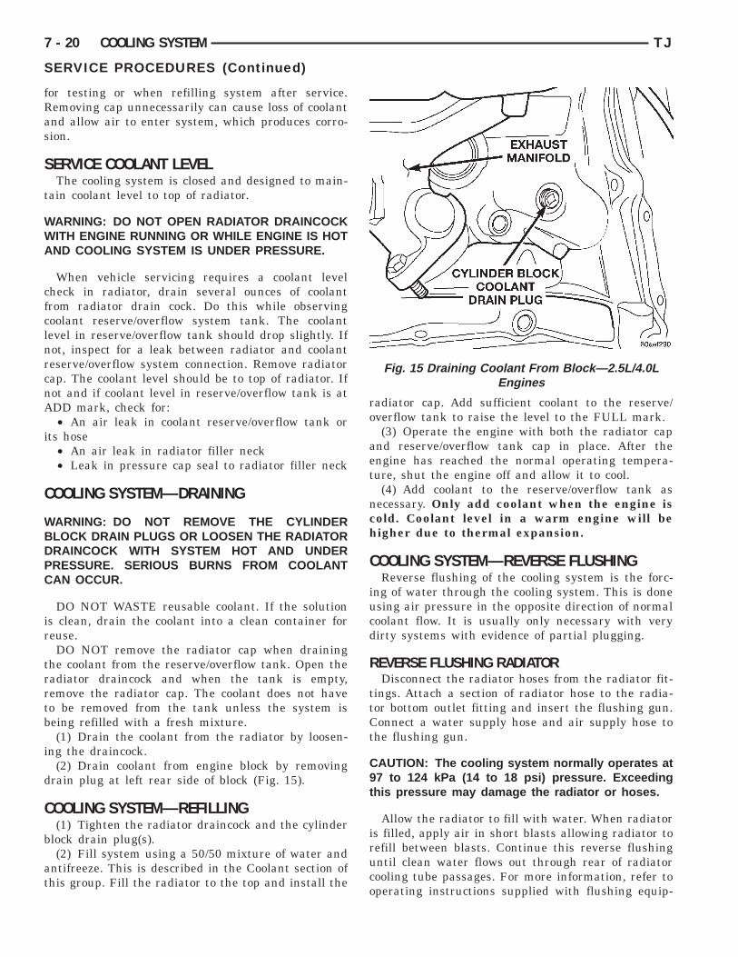
ng the draincock.(2) Drain coolant from engine block by removing
rain plug at left rear side of block (Fig. 15).
OOLING SYSTEM—REFILLING(1) Tighten the radiator draincock and the cylinder
lock drain plug(s).(2) Fill system using a 50/50 mixture of water and
ntifreeze. This is described in the Coolant section ofhis group. Fill the radiator to the top and install the
radiator cap. Add sufficient coolant to the reserve/overflow tank to raise the level to the FULL mark.
(3) Operate the engine with both the radiator capand reserve/overflow tank cap in place. After theengine has reached the normal operating tempera-ture, shut the engine off and allow it to cool.
(4) Add coolant to the reserve/overflow tank asnecessary. Only add coolant when the engine iscold. Coolant level in a warm engine will behigher due to thermal expansion.
COOLING SYSTEM—REVERSE FLUSHINGReverse flushing of the cooling system is the forc-
ing of water through the cooling system. This is doneusing air pressure in the opposite direction of normalcoolant flow. It is usually only necessary with verydirty systems with evidence of partial plugging.
REVERSE FLUSHING RADIATORDisconnect the radiator hoses from the radiator fit-
tings. Attach a section of radiator hose to the radia-tor bottom outlet fitting and insert the flushing gun.Connect a water supply hose and air supply hose tothe flushing gun.
CAUTION: The cooling system normally operates at97 to 124 kPa (14 to 18 psi) pressure. Exceedingthis pressure may damage the radiator or hoses.
Allow the radiator to fill with water. When radiatoris filled, apply air in short blasts allowing radiator torefill between blasts. Continue this reverse flushinguntil clean water flows out through rear of radiatorcooling tube passages. For more information, refer tooperating instructions supplied with flushing equip-
Fig. 15 Draining Coolant From Block—2.5L/4.0LEngines
mr
R
hircpi
twbCai
ssmThf
R
A
tt
bliIttdtvf
C
R
W
Cmd
TJ COOLING SYSTEM 7 - 21
SERVICE PROCEDURES (Continued)
ent. Have radiator cleaned more extensively by aadiator repair shop.
EVERSE FLUSHING ENGINEDrain the cooling system. Remove the thermostat
ousing and thermostat. Install the thermostat hous-ng. Disconnect the radiator upper hose from theadiator and attach the flushing gun to the hose. Dis-onnect the radiator lower hose from the waterump. Attach a lead away hose to the water pumpnlet fitting.
Connect the water supply hose and air supply hoseo the flushing gun. Allow the engine to fill withater. When the engine is filled, apply air in shortlasts, allowing the system to fill between air blasts.ontinue until clean water flows through the leadway hose. For more information, refer to operatingnstructions supplied with flushing equipment.
Remove the lead away hose, flushing gun, waterupply hose and air supply hose. Remove the thermo-tat housing and install thermostat. Install the ther-ostat housing with a replacement gasket. Refer tohermostat Replacement. Connect the radiatoroses. Refill the cooling system with the correct anti-reeze/water mixture.
EMOVAL AND INSTALLATION
UTOMATIC TRANSMISSION OIL COOLERThe internal transmission oil cooler located within
he radiator is not serviceable. If it requires service,he radiator must be replaced.
Once the repaired or replacement radiator haseen installed, fill the cooling system and inspect foreaks. Refer to the Filling Cooling System and Test-ng Cooling System For Leaks sections in this group.f the transmission operates properly after repairinghe leak, drain the transmission and remove theransmission oil pan. Inspect for sludge. Inspect for airty or plugged inlet filter. If none of these condi-ions are found, the transmission and torque con-erter may require reconditioning. Refer to Group 21or automatic transmission servicing.
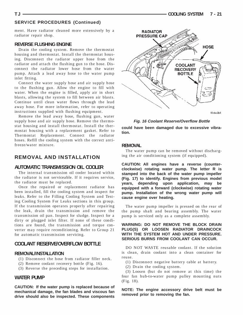
OOLANT RESERVE/OVERFLOW BOTTLE
EMOVAL/INSTALLATION(1) Disconnect the hose from radiator filler neck.(2) Remove coolant recovery bottle (Fig. 16).(3) Reverse the preceding steps for installation.
ATER PUMP
AUTION: If the water pump is replaced because ofechanical damage, the fan blades and viscous fanrive should also be inspected. These components
could have been damaged due to excessive vibra-tion.
REMOVALThe water pump can be removed without discharg-
ing the air conditioning system (if equipped).
CAUTION: All engines have a reverse (counter-clockwise) rotating water pump. The letter R isstamped into the back of the water pump impeller(Fig. 17) to identify. Engines from previous modelyears, depending upon application, may beequipped with a forward (clockwise) rotating waterpump. Installation of the wrong water pump willcause engine over heating.
The water pump impeller is pressed on the rear ofthe pump shaft and bearing assembly. The waterpump is serviced only as a complete assembly.
WARNING: DO NOT REMOVE THE BLOCK DRAINPLUG(S) OR LOOSEN RADIATOR DRAINCOCKWITH THE SYSTEM HOT AND UNDER PRESSURE.SERIOUS BURNS FROM COOLANT CAN OCCUR.
DO NOT WASTE reusable coolant. If the solutionis clean, drain coolant into a clean container forreuse.
(1) Disconnect negative battery cable at battery.(2) Drain the cooling system.(3) Loosen (but do not remove at this time) the
four fan hub-to-water pump pulley mounting nuts(Fig. 18).
NOTE: The engine accessory drive belt must beremoved prior to removing the fan.
Fig. 16 Coolant Reserve/Overflow Bottle

t
WAWTC6H
7 - 22 COOLING SYSTEM TJ
REMOVAL AND INSTALLATION (Continued)
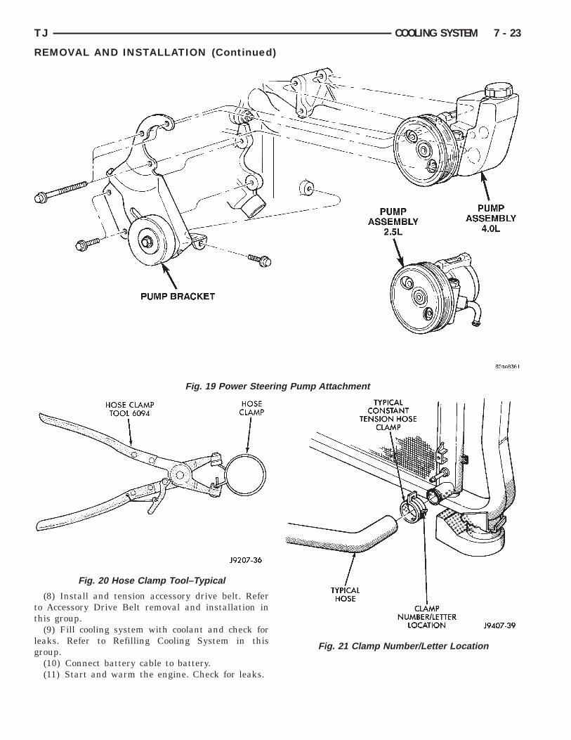
(4) Remove accessory drive belt.(5) Remove power steering pump (Fig. 19). (Refer
o Group 19 Steering).
ARNING: CONSTANT TENSION HOSE CLAMPSRE USED ON MOST COOLING SYSTEM HOSES.HEN REMOVING OR INSTALLING, USE ONLY
OOLS DESIGNED FOR SERVICING THIS TYPE OFLAMP, SUCH AS SPECIAL CLAMP TOOL (NUMBER094) (Fig. 20) SNAP-ON CLAMP TOOL (NUMBERPC-20) MAY BE USED FOR LARGER CLAMPS.
Fig. 17 Reverse Rotating Water Pump—Typical
Fig. 18 Fan Mounting Nuts
ALWAYS WEAR SAFETY GLASSES WHEN SERVIC-ING CONSTANT TENSION CLAMPS.
CAUTION: A number or letter is stamped into thetongue of constant tension clamps (Fig. 21). Ifreplacement is necessary, use only an originalequipment clamp with matching number or letter.
(6) Remove lower radiator hose from water pump.Remove heater hose from water pump fitting.
(7) Remove four nuts previously loosened andremove the fan blade assembly and pulley.
(8) After removing fan blade/viscous fan driveassembly, do not place thermal viscous fan drive inhorizontal position. If stored horizontally, siliconefluid in viscous fan drive could drain into its bearingassembly and contaminate lubricant.
(9) Remove the four pump mounting bolts (Fig. 22)and remove pump from vehicle. Discard old gasket.Note that one of the four bolts is longer than theother bolts.
(10) If pump is to be replaced, the heater hose fit-ting must be removed. Note position of fitting beforeremoval.
INSTALLATION(1) If pump is being replaced, install the heater
hose fitting to the pump. Use a sealant on the fittingsuch as Mopart Thread Sealant With Teflon. Refer tothe directions on the package.
(2) Clean the gasket mating surfaces. If the origi-nal pump is used, remove any deposits or other for-eign material. Inspect the cylinder block and waterpump mating surfaces for erosion or damage fromcavitation.
(3) Install the gasket and water pump. The sili-cone bead on the gasket should be facing the waterpump. Also, the gasket is installed dry. Tightenmounting bolts to 23 N·m (200 in. lbs.) torque. Rotatethe shaft by hand to be sure it turns freely.
(4) Connect the radiator and heater hoses to thewater pump.
(5) Position water pump pulley to water pumphub.
(6) Install fan and four nuts to water pump hub.Tighten or nuts to 27 N·m (20 ft. lbs.) torque.
(7) Install power steering pump.
CAUTION: When installing the serpentine engineaccessory drive belt, the belt MUST be routed cor-rectly. If not, the engine may overheat due to thewater pump rotating in the wrong direction. Refer tothe Belt Removal and Installation in this group forappropriate belt routing. You may also refer to theBelt Routing Label in the vehicle engine compart-ment.
tt
lg
TJ COOLING SYSTEM 7 - 23
REMOVAL AND INSTALLATION (Continued)
(8) Install and tension accessory drive belt. Refero Accessory Drive Belt removal and installation inhis group.
(9) Fill cooling system with coolant and check foreaks. Refer to Refilling Cooling System in thisroup.(10) Connect battery cable to battery.(11) Start and warm the engine. Check for leaks.
Fig. 19 Power Steer
Fig. 20 Hose Clamp Tool–Typical
ing Pump Attachment
Fig. 21 Clamp Number/Letter Location
T
R
WDSC
ir
l
WAWTC6HAI
Ct
7 - 24 COOLING SYSTEM TJ
REMOVAL AND INSTALLATION (Continued)
HERMOSTAT
EMOVAL
ARNING: DO NOT LOOSEN THE RADIATORRAINCOCK WITH THE SYSTEM HOT AND PRES-URIZED. SERIOUS BURNS FROM THE COOLANTAN OCCUR.
DO NOT WASTE reusable coolant. If the solutions clean, drain the coolant into a clean container foreuse.(1) Drain the coolant from the radiator until the
evel is below the thermostat housing.
ARNING: CONSTANT TENSION HOSE CLAMPSRE USED ON MOST COOLING SYSTEM HOSES.HEN REMOVING OR INSTALLING, USE ONLY
OOLS DESIGNED FOR SERVICING THIS TYPE OFLAMP, SUCH AS SPECIAL CLAMP TOOL (NUMBER094) (Fig. 20). SNAP-ON CLAMP TOOL (NUMBERPC-20) MAY BE USED FOR LARGER CLAMPS.LWAYS WEAR SAFETY GLASSES WHEN SERVIC-
NG CONSTANT TENSION CLAMPS.
AUTION: A number or letter is stamped into theongue of constant tension clamps (Fig. 21). If
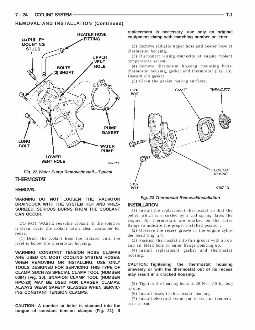
Fig. 22 Water Pump Remove/Install—Typical
replacement is necessary, use only an originalequipment clamp with matching number or letter.
(2) Remove radiator upper hose and heater hose atthermostat housing.
(3) Disconnect wiring connector at engine coolanttemperature sensor.
(4) Remove thermostat housing mounting bolts,thermostat housing, gasket and thermostat (Fig. 23).Discard old gasket.
(5) Clean the gasket mating surfaces.
INSTALLATION(1) Install the replacement thermostat so that the
pellet, which is encircled by a coil spring, faces theengine. All thermostats are marked on the outerflange to indicate the proper installed position.
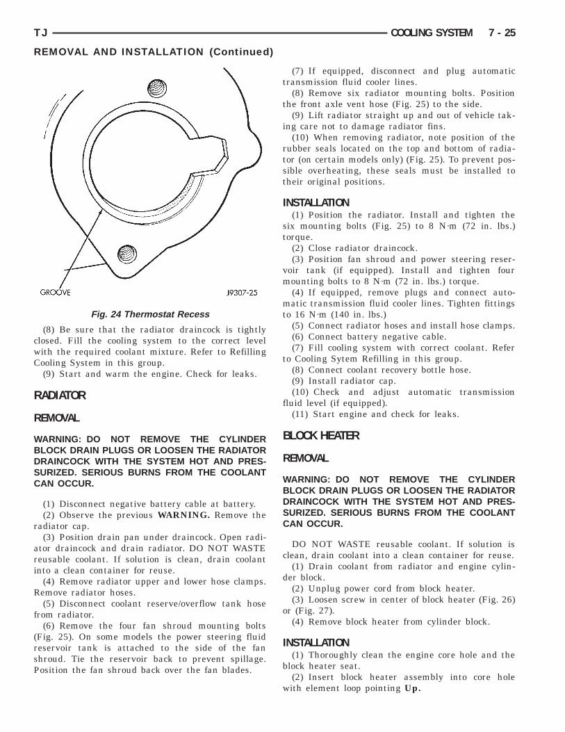
(2) Observe the recess groove in the engine cylin-der head (Fig. 24).
(3) Position thermostat into this groove with arrowand air bleed hole on outer flange pointing up.
(4) Install replacement gasket and thermostathousing.
CAUTION: Tightening the thermostat housingunevenly or with the thermostat out of its recessmay result in a cracked housing.
(5) Tighten the housing bolts to 20 N·m (15 ft. lbs.)torque.
(6) Install hoses to thermostat housing.(7) Install electrical connector to coolant tempera-
ture sensor.
Fig. 23 Thermostat Removal/Installation
cwC
R
R
WBDSC
r
ari
R
f
(rsP
TJ COOLING SYSTEM 7 - 25
REMOVAL AND INSTALLATION (Continued)
(8) Be sure that the radiator draincock is tightlylosed. Fill the cooling system to the correct levelith the required coolant mixture. Refer to Refillingooling System in this group.(9) Start and warm the engine. Check for leaks.
ADIATOR
EMOVAL
ARNING: DO NOT REMOVE THE CYLINDERLOCK DRAIN PLUGS OR LOOSEN THE RADIATORRAINCOCK WITH THE SYSTEM HOT AND PRES-URIZED. SERIOUS BURNS FROM THE COOLANTAN OCCUR.
(1) Disconnect negative battery cable at battery.(2) Observe the previous WARNING. Remove the
adiator cap.(3) Position drain pan under draincock. Open radi-
tor draincock and drain radiator. DO NOT WASTEeusable coolant. If solution is clean, drain coolantnto a clean container for reuse.
(4) Remove radiator upper and lower hose clamps.emove radiator hoses.(5) Disconnect coolant reserve/overflow tank hose
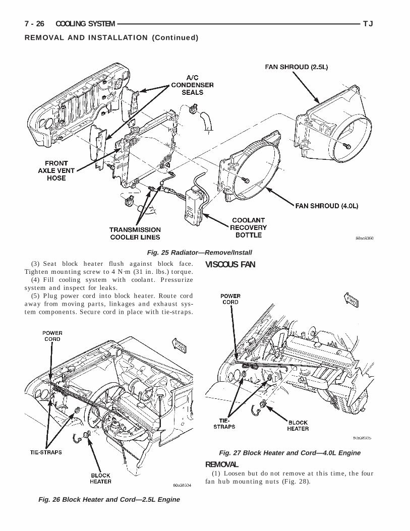
rom radiator.(6) Remove the four fan shroud mounting bolts
Fig. 25). On some models the power steering fluideservoir tank is attached to the side of the fanhroud. Tie the reservoir back to prevent spillage.osition the fan shroud back over the fan blades.
Fig. 24 Thermostat Recess
(7) If equipped, disconnect and plug automatictransmission fluid cooler lines.
(8) Remove six radiator mounting bolts. Positionthe front axle vent hose (Fig. 25) to the side.
(9) Lift radiator straight up and out of vehicle tak-ing care not to damage radiator fins.
(10) When removing radiator, note position of therubber seals located on the top and bottom of radia-tor (on certain models only) (Fig. 25). To prevent pos-sible overheating, these seals must be installed totheir original positions.
INSTALLATION(1) Position the radiator. Install and tighten the
six mounting bolts (Fig. 25) to 8 N·m (72 in. lbs.)torque.
(2) Close radiator draincock.(3) Position fan shroud and power steering reser-
voir tank (if equipped). Install and tighten fourmounting bolts to 8 N·m (72 in. lbs.) torque.
(4) If equipped, remove plugs and connect auto-matic transmission fluid cooler lines. Tighten fittingsto 16 N·m (140 in. lbs.)
(5) Connect radiator hoses and install hose clamps.(6) Connect battery negative cable.(7) Fill cooling system with correct coolant. Refer
to Cooling Sytem Refilling in this group.(8) Connect coolant recovery bottle hose.(9) Install radiator cap.(10) Check and adjust automatic transmission
fluid level (if equipped).(11) Start engine and check for leaks.
BLOCK HEATER
REMOVAL
WARNING: DO NOT REMOVE THE CYLINDERBLOCK DRAIN PLUGS OR LOOSEN THE RADIATORDRAINCOCK WITH THE SYSTEM HOT AND PRES-SURIZED. SERIOUS BURNS FROM THE COOLANTCAN OCCUR.
DO NOT WASTE reusable coolant. If solution isclean, drain coolant into a clean container for reuse.
(1) Drain coolant from radiator and engine cylin-der block.
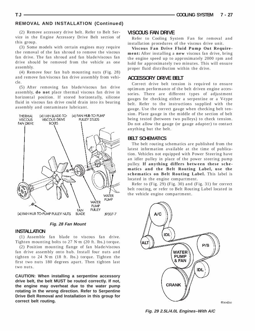
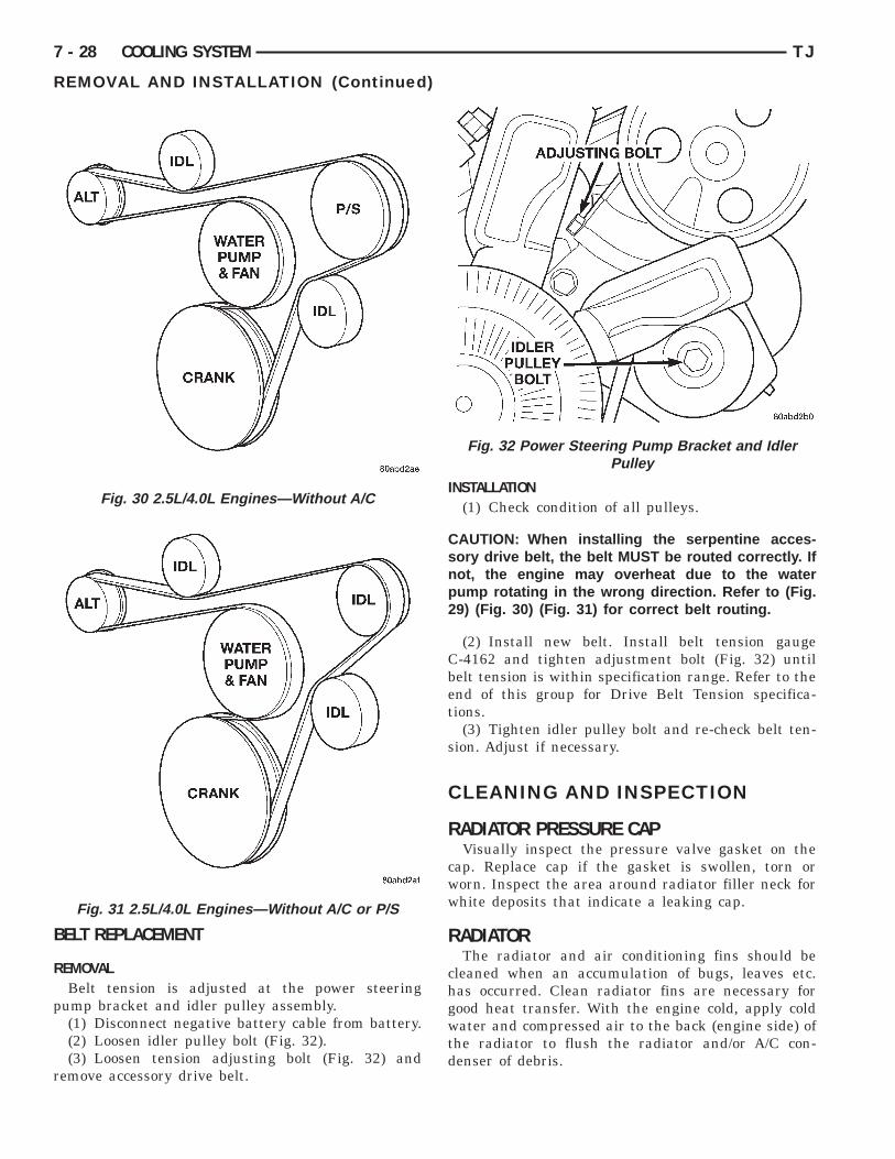
(2) Unplug power cord from block heater.(3) Loosen screw in center of block heater (Fig. 26)
or (Fig. 27).(4) Remove block heater from cylinder block.
INSTALLATION(1) Thoroughly clean the engine core hole and the
block heater seat.(2) Insert block heater assembly into core hole
with element loop pointing Up.
T
s
at
—R
7 - 26 COOLING SYSTEM TJ
REMOVAL AND INSTALLATION (Continued)
(3) Seat block heater flush against block face.ighten mounting screw to 4 N·m (31 in. lbs.) torque.(4) Fill cooling system with coolant. Pressurize
ystem and inspect for leaks.(5) Plug power cord into block heater. Route cord
way from moving parts, linkages and exhaust sys-em components. Secure cord in place with tie-straps.
Fig. 25 Radiator
Fig. 26 Block Heater and Cord—2.5L Engine
VISCOUS FAN
REMOVAL(1) Loosen but do not remove at this time, the four
fan hub mounting nuts (Fig. 28).
emove/Install
Fig. 27 Block Heater and Cord—4.0L Engine
vt
tfda
ac
ahfa
I
T
ftft
CdtrDc
thp
TJ COOLING SYSTEM 7 - 27
REMOVAL AND INSTALLATION (Continued)
(2) Remove accessory drive belt. Refer to Belt Ser-ice in the Engine Accessory Drive Belt section ofhis group.
(3) Some models with certain engines may requirehe removal of the fan shroud to remove the viscousan drive. The fan shroud and fan blade/viscous fanrive should be removed from the vehicle as onessembly.(4) Remove four fan hub mounting nuts (Fig. 28)
nd remove fan/viscous fan drive assembly from vehi-le.(5) After removing fan blade/viscous fan drive
ssembly, do not place thermal viscous fan drive inorizontal position. If stored horizontally, siliconeluid in viscous fan drive could drain into its bearingssembly and contaminate lubricant.
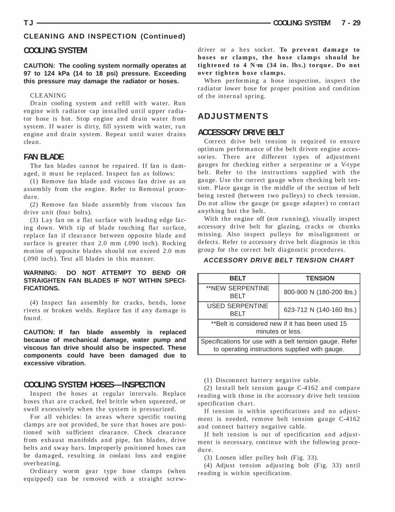
NSTALLATION(1) Assemble fan blade to viscous fan drive.
ighten mounting bolts to 27 N·m (20 ft. lbs.) torque.(2) Position mounting flange of fan blade/viscous
an drive assembly onto hub. Install four nuts andighten to 24 N·m (18 ft. lbs.) torque. Tighten theirst two nuts 180 degrees apart. Then tighten lastwo nuts.
AUTION: When installing a serpentine accessoryrive belt, the belt MUST be routed correctly. If not,
he engine may overheat due to the water pumpotating in the wrong direction. Refer to Serpentinerive Belt Removal and Installation in this group fororrect belt routing.
Fig. 28 Fan Mount
VISCOUS FAN DRIVERefer to Cooling System Fan for removal and
installation procedures of the viscous drive unit.Viscous Fan Drive Fluid Pump Out Require-
ment: After installing a new viscous fan drive, bringhe engine speed up to approximately 2000 rpm andold for approximately two minutes. This will ensureroper fluid distribution within the drive.
ACCESSORY DRIVE BELTCorrect drive belt tension is required to ensure
optimum performance of the belt driven engine acces-sories. There are different types of adjustmentgauges for checking either a serpentine or a V-typebelt. Refer to the instructions supplied with thegauge. Use the correct gauge when checking belt ten-sion. Place gauge in the middle of the section of beltbeing tested (between two pulleys) to check tension.Do not allow the gauge (or gauge adapter) to contactanything but the belt.
BELT SCHEMATICSThe belt routing schematics are published from the
latest information available at the time of publica-tion. Vehicles not equipped with Power Steering havean idler pulley in place of the power steering pumppulley. If anything differs between these sche-matics and the Belt Routing Label, use theschematics on Belt Routing Label. This label islocated in the engine compartment.
Refer to (Fig. 29) (Fig. 30) and (Fig. 31) for correctbelt routing, or refer to Belt Routing Label located inthe vehicle engine compartment.
Fig. 29 2.5L/4.0L Engines–With A/C
B
R
p
r
7 - 28 COOLING SYSTEM TJ
REMOVAL AND INSTALLATION (Continued)
ELT REPLACEMENT
EMOVALBelt tension is adjusted at the power steering
ump bracket and idler pulley assembly.(1) Disconnect negative battery cable from battery.(2) Loosen idler pulley bolt (Fig. 32).(3) Loosen tension adjusting bolt (Fig. 32) and
emove accessory drive belt.
Fig. 30 2.5L/4.0L Engines—Without A/C
Fig. 31 2.5L/4.0L Engines—Without A/C or P/S
INSTALLATION(1) Check condition of all pulleys.
CAUTION: When installing the serpentine acces-sory drive belt, the belt MUST be routed correctly. Ifnot, the engine may overheat due to the waterpump rotating in the wrong direction. Refer to (Fig.29) (Fig. 30) (Fig. 31) for correct belt routing.
(2) Install new belt. Install belt tension gaugeC-4162 and tighten adjustment bolt (Fig. 32) untilbelt tension is within specification range. Refer to theend of this group for Drive Belt Tension specifica-tions.
(3) Tighten idler pulley bolt and re-check belt ten-sion. Adjust if necessary.
CLEANING AND INSPECTION
RADIATOR PRESSURE CAPVisually inspect the pressure valve gasket on the
cap. Replace cap if the gasket is swollen, torn orworn. Inspect the area around radiator filler neck forwhite deposits that indicate a leaking cap.
RADIATORThe radiator and air conditioning fins should be
cleaned when an accumulation of bugs, leaves etc.has occurred. Clean radiator fins are necessary forgood heat transfer. With the engine cold, apply coldwater and compressed air to the back (engine side) ofthe radiator to flush the radiator and/or A/C con-denser of debris.
Fig. 32 Power Steering Pump Bracket and IdlerPulley
C
C9t
etsec
F
a
ad
d
irsm(
WSF
rf
Cbvce
C
hs
ctfbbo
e
TJ COOLING SYSTEM 7 - 29
CLEANING AND INSPECTION (Continued)
OOLING SYSTEM
AUTION: The cooling system normally operates at7 to 124 kPa (14 to 18 psi) pressure. Exceeding
his pressure may damage the radiator or hoses.
CLEANINGDrain cooling system and refill with water. Run
ngine with radiator cap installed until upper radia-or hose is hot. Stop engine and drain water fromystem. If water is dirty, fill system with water, runngine and drain system. Repeat until water drainslean.
AN BLADEThe fan blades cannot be repaired. If fan is dam-
ged, it must be replaced. Inspect fan as follows:(1) Remove fan blade and viscous fan drive as an
ssembly from the engine. Refer to Removal proce-ure.(2) Remove fan blade assembly from viscous fan
rive unit (four bolts).(3) Lay fan on a flat surface with leading edge fac-
ng down. With tip of blade touching flat surface,eplace fan if clearance between opposite blade andurface is greater than 2.0 mm (.090 inch). Rockingotion of opposite blades should not exceed 2.0 mm
.090 inch). Test all blades in this manner.
ARNING: DO NOT ATTEMPT TO BEND ORTRAIGHTEN FAN BLADES IF NOT WITHIN SPECI-ICATIONS.
(4) Inspect fan assembly for cracks, bends, looseivets or broken welds. Replace fan if any damage isound.
AUTION: If fan blade assembly is replacedecause of mechanical damage, water pump andiscous fan drive should also be inspected. Theseomponents could have been damaged due toxcessive vibration.
OOLING SYSTEM HOSES—INSPECTIONInspect the hoses at regular intervals. Replace
oses that are cracked, feel brittle when squeezed, orwell excessively when the system is pressurized.For all vehicles: In areas where specific routing
lamps are not provided, be sure that hoses are posi-ioned with sufficient clearance. Check clearancerom exhaust manifolds and pipe, fan blades, driveelts and sway bars. Improperly positioned hoses cane damaged, resulting in coolant loss and engineverheating.Ordinary worm gear type hose clamps (when
quipped) can be removed with a straight screw-
driver or a hex socket. To prevent damage tohoses or clamps, the hose clamps should betightened to 4 N·m (34 in. lbs.) torque. Do notover tighten hose clamps.
When performing a hose inspection, inspect theradiator lower hose for proper position and conditionof the internal spring.
ADJUSTMENTS
ACCESSORY DRIVE BELTCorrect drive belt tension is required to ensure
optimum performance of the belt driven engine acces-sories. There are different types of adjustmentgauges for checking either a serpentine or a V-typebelt. Refer to the instructions supplied with thegauge. Use the correct gauge when checking belt ten-sion. Place gauge in the middle of the section of beltbeing tested (between two pulleys) to check tension.Do not allow the gauge (or gauge adapter) to contactanything but the belt.
With the engine off (not running), visually inspectaccessory drive belt for glazing, cracks or chunksmissing. Also inspect pulleys for misalignment ordefects. Refer to accessory drive belt diagnosis in thisgroup for the correct belt diagnostic procedures.
(1) Disconnect battery negative cable.(2) Install belt tension gauge C-4162 and compare
reading with those in the accessory drive belt tensionspecification chart.
If tension is within specifications and no adjust-ment is needed, remove belt tension gauge C-4162and connect battery negative cable.
If belt tension is out of specification and adjust-ment is necessary, continue with the following proce-dure.
(3) Loosen idler pulley bolt (Fig. 33).(4) Adjust tension adjusting bolt (Fig. 33) until
reading is within specification.
ACCESSORY DRIVE BELT TENSION CHART
BELT TENSION
**NEW SERPENTINEBELT
800-900 N (180-200 lbs.)
USED SERPENTINEBELT
623-712 N (140-160 lbs.)
**Belt is considered new if it has been used 15minutes or less.
Specifications for use with a belt tension gauge. Referto operating instructions supplied with gauge.
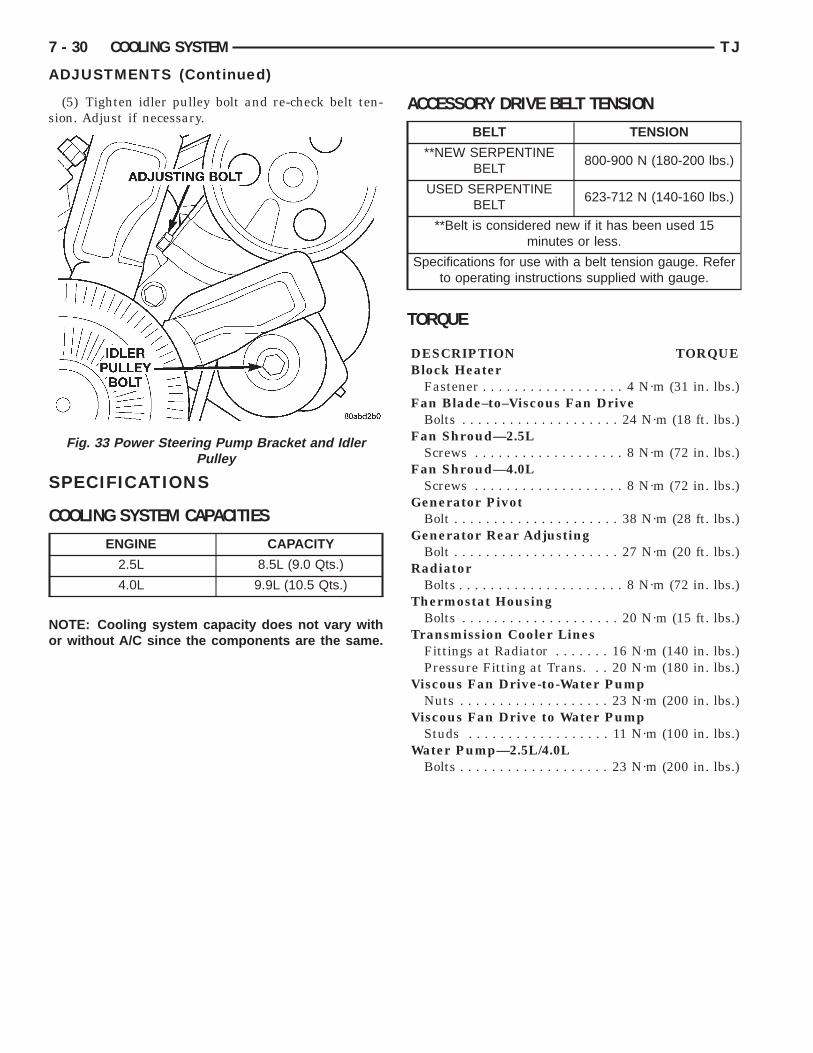
s
S
C
No
7 - 30 COOLING SYSTEM TJ
ADJUSTMENTS (Continued)
(5) Tighten idler pulley bolt and re-check belt ten-ion. Adjust if necessary.
PECIFICATIONS
OOLING SYSTEM CAPACITIES
OTE: Cooling system capacity does not vary withr without A/C since the components are the same.
Fig. 33 Power Steering Pump Bracket and IdlerPulley
ENGINE CAPACITY
2.5L 8.5L (9.0 Qts.)
4.0L 9.9L (10.5 Qts.)
ACCESSORY DRIVE BELT TENSION
TORQUE
DESCRIPTION TORQUEBlock Heater
Fastener . . . . . . . . . . . . . . . . . . 4 N·m (31 in. lbs.)Fan Blade–to–Viscous Fan Drive
Bolts . . . . . . . . . . . . . . . . . . . . 24 N·m (18 ft. lbs.)Fan Shroud—2.5L
Screws . . . . . . . . . . . . . . . . . . . 8 N·m (72 in. lbs.)Fan Shroud—4.0L
Screws . . . . . . . . . . . . . . . . . . . 8 N·m (72 in. lbs.)Generator Pivot
Bolt . . . . . . . . . . . . . . . . . . . . . 38 N·m (28 ft. lbs.)Generator Rear Adjusting
Bolt . . . . . . . . . . . . . . . . . . . . . 27 N·m (20 ft. lbs.)Radiator
Bolts . . . . . . . . . . . . . . . . . . . . . 8 N·m (72 in. lbs.)Thermostat Housing
Bolts . . . . . . . . . . . . . . . . . . . . 20 N·m (15 ft. lbs.)Transmission Cooler Lines
Fittings at Radiator . . . . . . . 16 N·m (140 in. lbs.)Pressure Fitting at Trans. . . 20 N·m (180 in. lbs.)
Viscous Fan Drive-to-Water PumpNuts . . . . . . . . . . . . . . . . . . . 23 N·m (200 in. lbs.)
Viscous Fan Drive to Water PumpStuds . . . . . . . . . . . . . . . . . . 11 N·m (100 in. lbs.)
Water Pump—2.5L/4.0LBolts . . . . . . . . . . . . . . . . . . . 23 N·m (200 in. lbs.)
BELT TENSION
**NEW SERPENTINEBELT
800-900 N (180-200 lbs.)
USED SERPENTINEBELT
623-712 N (140-160 lbs.)
**Belt is considered new if it has been used 15minutes or less.
Specifications for use with a belt tension gauge. Referto operating instructions supplied with gauge.
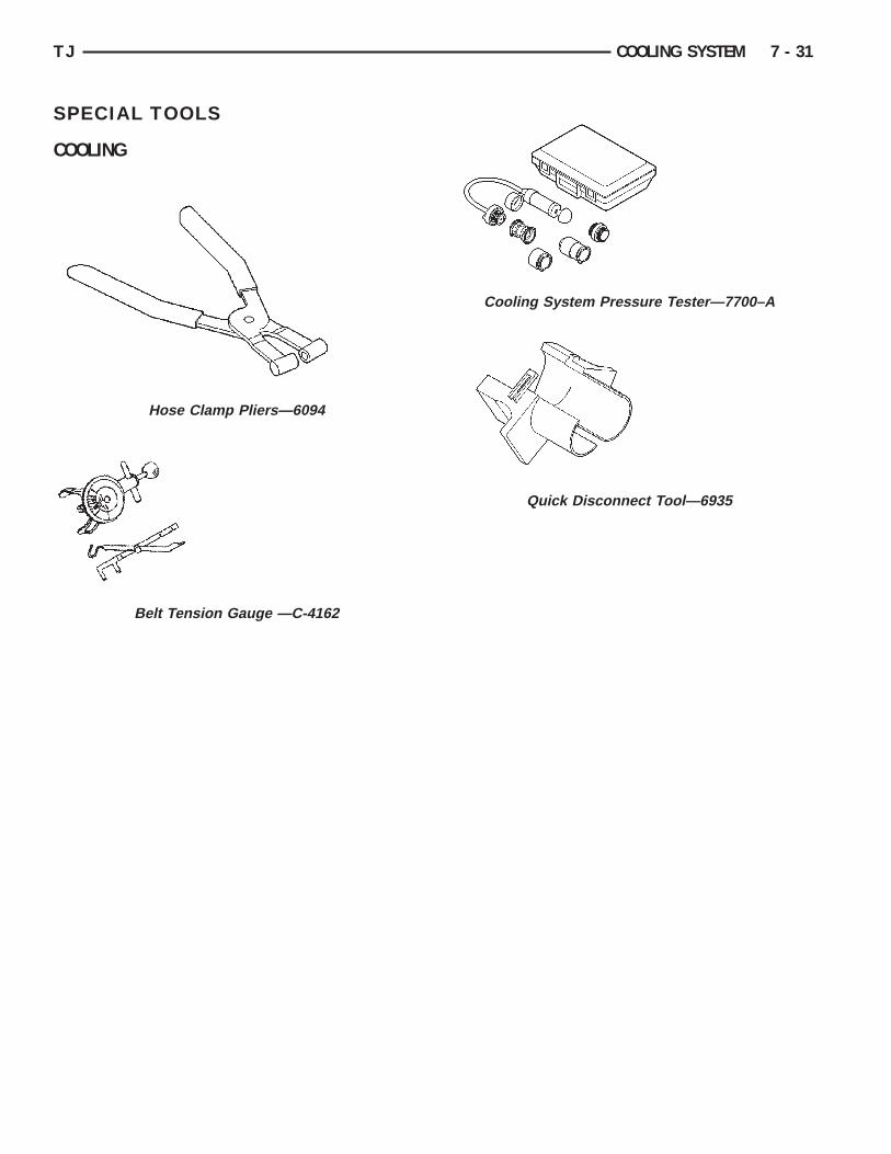
S
C
TJ COOLING SYSTEM 7 - 31
PECIAL TOOLS
OOLING
Hose Clamp Pliers—6094
Belt Tension Gauge —C-4162
Cooling System Pressure Tester—7700–A
Quick Disconnect Tool—6935